New SMC Pneumatics IZN10 Ionizer/Nozzle type · 2011. 6. 6. · CAT.ES100-72A Courtesy of Steven...
28
Series IZN10 Ionizer Nozzle type Outputs maintenance signal when detects stain or wear of an electrode needle always. Detects optimal maintenance time, reduced labor for maintenance. High-voltage power supply cable/ external high-voltage power supply are unnecessary. Electrode needle contamination detector With built-in power supply substrate 16 mm 16 mm Removing dust from lamp cover Eliminating static electricity from IC chip Ion balance ±10 v Slim design: Thickness dimension 16 mm RoHS compliant Ion balance ±10 v Slim design: Thickness dimension 16 mm RoHS compliant (In case of energy saving static electricity elimination nozzle) 1 2 1 2 • Eliminates dust clinging to lamp cover. • Prevents electrostatic breakdown of electric parts. • Prevents detachment failure. Dust removal and static electricity elimination by air blow Spot type static electricity elimination CAT.ES100-72A Courtesy of Steven Engineering, Inc.-230 Ryan Way, South San Francisco, CA 94080-6370-Main Office: (650) 588-9200-Outside Local Area: (800) 258-9200-www.stevenengineering.com
Transcript of New SMC Pneumatics IZN10 Ionizer/Nozzle type · 2011. 6. 6. · CAT.ES100-72A Courtesy of Steven...
Series IZN10
IonizerNozzle type
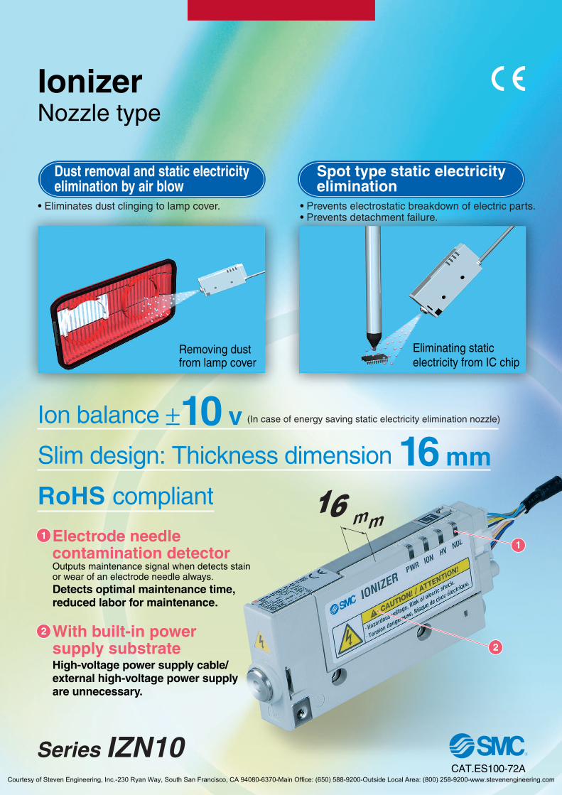
Outputs maintenance signal when detects stainor wear of an electrode needle always.Detects optimal maintenance time,reduced labor for maintenance.
High-voltage power supply cable/external high-voltage power supplyare unnecessary.
Electrode needle contamination detector
With built-in powersupply substrate
16 mm16 mm
Removing dustfrom lamp cover
Eliminating staticelectricity from IC chip
Ion balance ±10 vSlim design: Thickness dimension 16 mm
RoHS compliant
Ion balance ±10 vSlim design: Thickness dimension 16 mm
RoHS compliant
(In case of energy saving static electricity elimination nozzle)
1
2
1
2
• Eliminates dust clinging to lamp cover. • Prevents electrostatic breakdown of electric parts.• Prevents detachment failure.
Dust removal and static electricityelimination by air blow
Spot type static electricityelimination
CAT.ES100-72ACourtesy of Steven Engineering, Inc.-230 Ryan Way, South San Francisco, CA 94080-6370-Main Office: (650) 588-9200-Outside Local Area: (800) 258-9200-www.stevenengineering.com

Nozzle type can be selectedaccording to applications.Nozzle type can be selectedaccording to applications.
In cases with same air consumption,static electricity is eliminated in half the time.(Supply pressure 0.3 MPa)
External air inlet
Air consumption flow ratel/min (ANR)
Static electricityelimination time∗ sec
Ionized air flow velocity∗ m/s
None
10
5
0.4
Yes
10
2.5
2.5
Ion balance: ±10 VIncreases flow volume by external air intake
Ionized air assistedby the compressed air
• Improved dust removal performance by the energy ofcompressed air.
• Suitable for static electricity elimination at a longdistance (max. 500 mm).
Ion balance: ±15 V
Static electricity elimination is possible with minimal air consumption.External air inlet
External air inlet
Compressed air
Compressedair
External air
External air
Ionized air
Compressed airfor assisting
Compressed airfor generating ions
Compressedair
Ionized air
• Prevents electrostaticbreakdown of electricparts.
• Removes dust from lens.• Prevents adhesion of
dust.
• Prevents static electricity chargingwhen opening bags.
• Prevents static electricity cling on theinside of candy bags.
• Prevents problemswith the separation ofmolded plastic goods.
• Removes dust clinging to cup interiors.
• Prevents clogging of parts feeder.
Nozzle
External air inlet
Long range static electricity elimination and dust removalLong range static electricity elimination and dust removal
Energy saving static electricity elimination nozzle
High flow static electricity elimination nozzle
Eliminating static electricityfrom an electric substrate
Eliminating static electricityfrom molded goods
Eliminating static electricityfrom lens
Eliminating static electricityfrom plastic cups
Eliminating static electricityfrom packing films
Eliminating static electricityfrom parts feeder
Short range static electricity elimination,Design focuses on ion balance.Short range static electricity elimination,Design focuses on ion balance.
∗ At 300 mm distance
Reduced by 50%
Improved
6 times
Features 1Courtesy of Steven Engineering, Inc.-230 Ryan Way, South San Francisco, CA 94080-6370-Main Office: (650) 588-9200-Outside Local Area: (800) 258-9200-www.stevenengineering.com

Possible to conduct maintenance on the electrode needle without removal of body.No need to readjust the nozzle angle when the ionizer is restarted.
Possible to conduct maintenance withoutremoval of body.
Tools unnecessary for the installation or removalof the cartridge!
CartridgeBody
Electrode needle
Compressed air
Abnormalpressure
occurrenceStop
Abnormalpressuredetection
Pressure switch
Ionizer
Prevents static electricity eliminationtrouble due to pressure drop of compressed air.Emission of static electricity is suspended when abnormal purge air pressure is detected by pressure switch.
Energy saving with electrostaticsensorEmission of static electricity is suspended when an electrostatic sensor detects that static electricity elimination is completed.
StopChargedpotential
measurement
Staticelectricity
eliminationcompleted
Electrostaticsensor monitor
Ionizer
External switch input function (2 inputs)External switch input function (2 inputs)
Easy maintenanceEasy maintenance
Features 2Courtesy of Steven Engineering, Inc.-230 Ryan Way, South San Francisco, CA 94080-6370-Main Office: (650) 588-9200-Outside Local Area: (800) 258-9200-www.stevenengineering.com
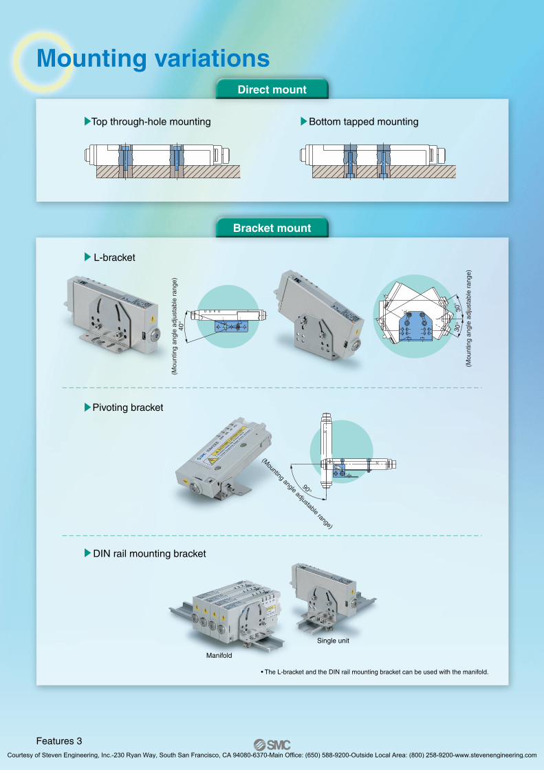
Top through-hole mounting Bottom tapped mounting
L-bracket
Pivoting bracket
DIN rail mounting bracket
(Mou
ntin
g an
gle
adju
stab
le r
ange
)
30°
30°
(Mounting angle adjustable range)
90°
40°
(Mou
ntin
g an
gle
adju
stab
le r
ange
)
Single unit
Manifold
• The L-bracket and the DIN rail mounting bracket can be used with the manifold.
Mounting variationsMounting variationsDirect mount
Bracket mount
Features 3Courtesy of Steven Engineering, Inc.-230 Ryan Way, South San Francisco, CA 94080-6370-Main Office: (650) 588-9200-Outside Local Area: (800) 258-9200-www.stevenengineering.com

Series IZN10Technical Data 1
Static Electricity Elimination Characteristics(Static Electricity Elimination Time from 1000 V to 100 V)
Note 1) If a pressure over the maximum operating pressure is applied, the electrode needle contamination detector will work and turn on the LED.• The ion generating efficiency of the high frequency AC type ionizer will decrease when the pressure around the electrode needle reaches 0.1
MPa or more, due to its ion generating mechanism. This means that even when the electrode needle is not contaminated, the electrode needle contamination detector may work depending on the condition of the connected tube and other reasons.
• In the range where the contamination detection signal is generated, a small amount of ions are still generated, so it can be used in some operating conditions. In this case, please consider using a type without the contamination detector. (Page 5)
• When the tube is connected using the female threads for piping / IZN10-11, be sure to check static electricity elimination performance beforehand. Note 2) The ionizer generates a small amount of ozone. Select ozone-resistant fittings for the female threads for piping. Also, regularly check there is
no deterioration due to ozone.
(1) Energy saving static electricity elimination nozzle / IZN10-01 (2) High flow rate nozzle / IZN10-02
(3) Female threads for piping / IZN10-11 With Stainless steel 316 one-touch fitting / KQG + Anti-static tubing / TA
KQG06-01S + TA0604 (Tube I.D.: 4 mm)∗ Static electricity elimination time at a distance of 50 mm from the end of tube.
KQG08-01S + TA0805 (Tube I.D.: 5 mm)
0 400200
5
4
3
2
1
0
0.1 MPa 0.05 MPa
0.7 MPa
0.3 MPa
0.5 MPaSta
tic e
lect
ricity
elim
inat
ion
time:
[sec
]
Static electricity elimination distance: [mm]
∗ Maximum operating pressure is 0.1 MPa.Note 1)
0 100 200 300 400 500
5
4
3
2
1
0
0.05 MPa
0.1 MPa
Sta
tic e
lect
ricity
elim
inat
ion
time:
[sec
]
Tube length: [mm]∗ Maximum operating pressure is 0.3 MPa.Note 1)
5
4
3
2
1
00 100 200 300 400 500
0.1 MPa
0.3 MPa
0.05 MPa
Tube length: [mm]
Sta
tic e
lect
ricity
elim
inat
ion
time:
[sec
]
Note) Static electricity elimination features are based on the data using the charged plate (size: 150 mm x 150 mm, capacitance: 20 pF) as defined in the U.S. ANSI standards (ANSI/ESD, STM3, 1-2000). Use this as a guideline purpose only for model selection because the value varies depending on the material and/or size of a subject.
5
4
3
2
1
00 200 400 500
Static electricity elimination distance: [mm]
Sta
tic e
lect
ricity
elim
inat
ion
time:
[sec
]
0.1 MPa
0.5 MPa
0.7 MPa
0.3 MPa
0.05 MPa
1Courtesy of Steven Engineering, Inc.-230 Ryan Way, South San Francisco, CA 94080-6370-Main Office: (650) 588-9200-Outside Local Area: (800) 258-9200-www.stevenengineering.com
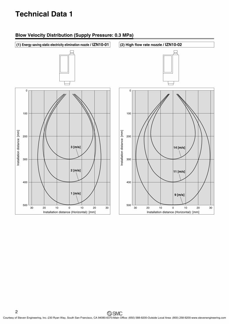
Blow Velocity Distribution (Supply Pressure: 0.3 MPa)
(1) Energy saving static electricity elimination nozzle / IZN10-01 (2) High flow rate nozzle / IZN10-02
Inst
alla
tion
dist
ance
: [m
m]
Installation distance (Horizontal): [mm]
0
100
200
300
400
5003030 20 10 0 10 20
3 [m/s]
2 [m/s]
1 [m/s]
Inst
alla
tion
dist
ance
: [m
m]
Installation distance (Horizontal): [mm]
0
100
200
300
400
5003030 20 10 0 10 20
14 [m/s]
11 [m/s]
9 [m/s]
Technical Data 1
2Courtesy of Steven Engineering, Inc.-230 Ryan Way, South San Francisco, CA 94080-6370-Main Office: (650) 588-9200-Outside Local Area: (800) 258-9200-www.stevenengineering.com

Series IZN10Technical Data 2
Flow Characteristics
(1) Energy saving static electricity elimination nozzle / IZN10-01(2) High flow rate nozzle / IZN10-02
(3) Female threads for piping / IZN10-11 With Stainless steel 316 one-touch fitting / KQG + Anti-static tubing / TA
Fig. 1: Flow characteristics measuring circuit
TU0604: Length 10 mm
Pressure gauge
Ionizer
KQT06-00: Union tee fittingFlow meter
Pre
ssur
e: [M
Pa]
Flow rate: [l/min (ANR)]
0.7
0.6
0.5
0.4
0.3
0.2
0.1
00 50 100 150 200 250
Energy saving static electricityelimination nozzle / IZN10-01
High flow rate nozzle /IZN10-02
Pre
ssur
e: [M
Pa]
Flow rate: [l/min (ANR)]
0.3
0.25
0.2
0.15
0.1
0.05
00 100 200 300
ø6-500 [mm]
ø8-100 [mm]ø8-500 [mm]
ø6-100 [mm]
Note) When a pressure above each line is used, the electrode needle contamination detector will work and turn on the LED.
(Refer to the bottom note on page 1.)
3Courtesy of Steven Engineering, Inc.-230 Ryan Way, South San Francisco, CA 94080-6370-Main Office: (650) 588-9200-Outside Local Area: (800) 258-9200-www.stevenengineering.com
Series IZN10Technical Data 3
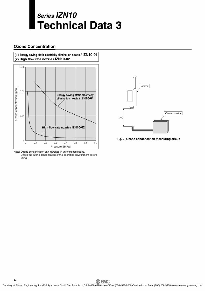
Ozone Concentration
(1) Energy saving static electricity elimination nozzle / IZN10-01(2) High flow rate nozzle / IZN10-02
Ionizer
Ozone monitor
300
Fig. 2: Ozone condensation measuring circuit
Ozo
ne c
once
ntra
tion:
[ppm
]
Pressure: [MPa]
0.03
0.02
0.01
00 0.1 0.2 0.3 0.4 0.5 0.6 0.7
High flow rate nozzle / IZN10-02
Energy saving static electricityelimination nozzle / IZN10-01
Note) Ozone condensation can increase in an enclosed space. Check the ozone condensation of the operating environment beforeusing.
4Courtesy of Steven Engineering, Inc.-230 Ryan Way, South San Francisco, CA 94080-6370-Main Office: (650) 588-9200-Outside Local Area: (800) 258-9200-www.stevenengineering.com

How to Order
Ionizer
Series IZN10
01 PIZN10 06High frequency AC nozzle type
Note) Used with a fitting and a tube on the end
Female threads for piping Note) Rc1/8
Symbol
01
02
11
Nozzle type
NPN output
PNP output
Nil
P
Output specification
With power supply cable (3 m)
With power supply cable (10 m)
Without power supply cable
Nil
Z
N
Power supply cable
ø6: Metric size
ø6.35 (1/4): Inch size
ø6: Metric size (Elbow)
ø6.35 (1/4): Inch size (Elbow)
06
07
16
17
Port size
∗ Refer to page 6.
Without bracket
With L-bracket
With pivoting bracket
With DIN rail mounting bracket
Nil
B1
B2
B3
Bracket
Made to Order
Non-standard power supply cable lengthHow to Order Contents/Specifications
Model with made-to-order power supply cableAvailable in 1 m increments from 1 m to 20 m.
Note) Use standard power supply cables for 3 m and 10 m lengths.
IZN10 CP 01 X13
Cable length
1 m
2 m
19 m
20 m
Symbol
01
02
19
20
Without electrode needle contamination detectorHow to Order Contents/Specifications
11IZN10
Fill in the standard model type shown above.
X194
Without electrode needle contamination detector
With this specification, contamination detection signal is not generated when the pressure around the electrode needle increases due to tube piping etc. This specification is recommended when the tube needs to be extended.• The ion generating efficiency of the high frequency AC type ionizer will
decrease when the pressure around the electrode needle reaches 0.1 MPa or more, due to its ion generating mechanism, and the contamination detection signal will be generated. However, in the range where the contamination detection signal is generated, a small amount of ions are still generated, so it can be used in some operating conditions.
. . .
. . .
Type
Energy saving static electricity elimination nozzle
High flow rate nozzle
5Courtesy of Steven Engineering, Inc.-230 Ryan Way, South San Francisco, CA 94080-6370-Main Office: (650) 588-9200-Outside Local Area: (800) 258-9200-www.stevenengineering.com

6
Accessories
Bracket
Fixed mounting Pivot mounting
Single unit
∗ The L-bracket and the DIN rail mounting bracket can be used with the manifold.
Manifold∗
Repair Parts
• L-bracket / IZN10-B1
Power supply cable• IZN10-CP (3 m)• IZN10-CPZ (10 m)
• Pivoting bracket / IZN10-B2
• DIN rail mounting bracket / IZN10-B3
Electrode needle assembly / IZN10-NT
Body assembly / IZN10-A002-
Cartridge assembly / IZN10-A003-
Electrode needle assembly
01 06
Type
Energy saving static electricityelimination nozzle
High flow rate nozzle
Female threads for piping Rc1/8
Symbol
0211
01
Nozzle shapeø6: metric size
ø6.35 (1/4"): inch size
ø6: metric size (elbow)
ø6.35 (11/4"): inch size (elbow)
06071617
Piping diameter
NPN output
PNP output
Nil
P
Output type
Series IZN10
333-IZN10-CT.qxd 10.12.15 5:44 PM Page 1
Courtesy of Steven Engineering, Inc.-230 Ryan Way, South San Francisco, CA 94080-6370-Main Office: (650) 588-9200-Outside Local Area: (800) 258-9200-www.stevenengineering.com
Spacer (5 mm)Hexagon socket headcap screw
17 (Mounting pitch)
Bracket ∗
(Order it separately.)
Hexagon nut
Ionizer ∗
(Order it separately.)
9.5
L1
L2
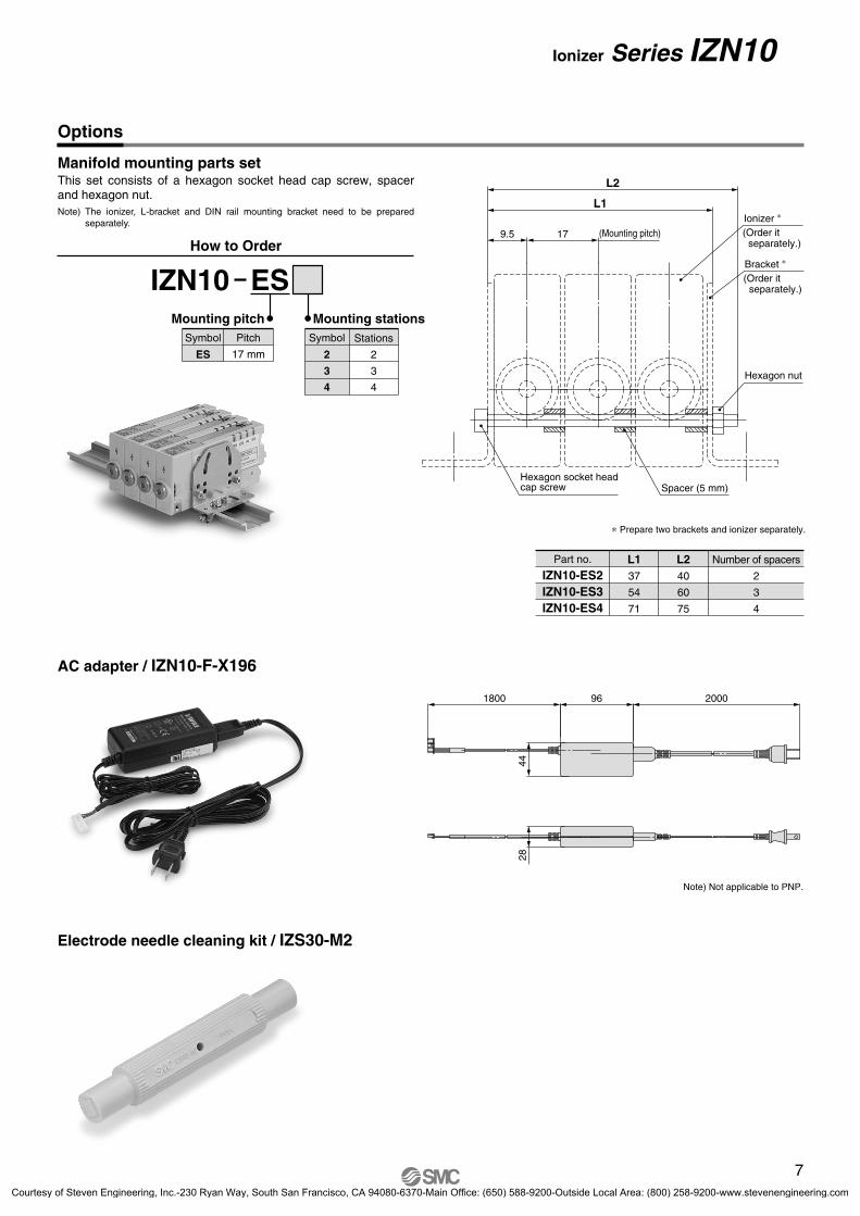
Options
Manifold mounting parts set
Electrode needle cleaning kit / IZS30-M2
AC adapter / IZN10-F-X196
This set consists of a hexagon socket head cap screw, spacer and hexagon nut. Note) The ionizer, L-bracket and DIN rail mounting bracket need to be prepared
separately.
How to Order
IZN10 ES
Pitch
17 mm
Symbol
ES
Mounting pitchStations
2
3
4
Symbol
2
3
4
Mounting stations
L137
54
71
L240
60
75
Part no.
IZN10-ES2IZN10-ES3IZN10-ES4
Number of spacers
2
3
4
Note) Not applicable to PNP.
∗ Prepare two brackets and ionizer separately.28
44
1800 96 2000
7
Ionizer Series IZN10
Courtesy of Steven Engineering, Inc.-230 Ryan Way, South San Francisco, CA 94080-6370-Main Office: (650) 588-9200-Outside Local Area: (800) 258-9200-www.stevenengineering.com
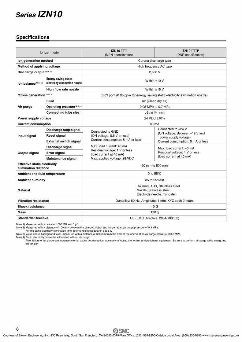
Specifications
Note 1) Measured with a probe of 1000 MΩ and 5 pF. Note 2) Measured with a distance of 100 mm between the charged object and ionizer at an air purge pressure of 0.3 MPa.
For the static electricity elimination time, refer to technical data on page 1. Note 3) Value above background level, measured with a distance of 300 mm from the front of the nozzle at an air purge pressure of 0.3 MPa. Note 4) Static electricity cannot be eliminated without air purge.
Also, failure of air purge can increase internal ozone condensation, adversely affecting the ionizer and peripheral equipment. Be sure to perform air purge while energizing the ionizer.
Ionizer model IZN10-(NPN specification)
IZN10-P(PNP specification)
Ion generation method
Method of applying voltage
Discharge output Note 1)
Ion balance Note 2)
Ozone generation Note 3)
Corona discharge type
High frequency AC type
2,500 V
Within ±10 V
Within ±15 V
0.03 ppm (0.05 ppm for energy saving static electricity elimination nozzle)
Air (Clean dry air)
0.05 MPa to 0.7 MPa
ø6 / ø1/4 inch
24 VDC ±10%
80 mA
20 mm to 500 mm
0 to 55°C
35 to 65%Rh
Durability: 50 Hz, Amplitude: 1 mm, XYZ each 2 hours
10 G
120 g
Connected to GND (ON voltage: 0.6 V or less)Current consumption: 5 mA or less
Connected to +24 V(ON voltage: Between +19 V andpower supply voltage)
Current consumption: 5 mA or less
Max. load current: 40 mAResidual voltage: 1 V or less(load current at 40 mA)Max. applied voltage: 28 VDC
Housing: ABS, Stainless steelNozzle: Stainless steelElectrode needle: Tungsten
CE (EMC Directive: 2004/108/EC)
Max. load current: 40 mAResidual voltage: 1 V or less(load current at 40 mA)
Air purge
Power supply voltage
Current consumption
Input signal
Output signal
Effective static electricityelimination distance
Material
Ambient humidity
Ambient and fluid temperature
Vibration resistance
Shock resistance
Mass
Standards/Directive
Discharge stop signal
Reset signal
External switch signal
Discharge signal
Error signal
Maintenance signal
Fluid
Operating pressure Note 4)
Connecting tube size
Energy saving staticelectricity elimination nozzle
High flow rate nozzle
8
Series IZN10
Courtesy of Steven Engineering, Inc.-230 Ryan Way, South San Francisco, CA 94080-6370-Main Office: (650) 588-9200-Outside Local Area: (800) 258-9200-www.stevenengineering.com

Functions
1. Electrode needle contamination detectionDetects lowered static electricity elimination performance due to contamination or wear of the electrode needle. The maintenance LED lights up and maintenance signal is generated.
2. Signal inputs by external switchThere are 2 ports for external switch signal inputs.
Description Symbol
Power supply display
Discharge
Irregular high voltage display
Maintenance display
PWR
ION
HV
NDL
Color
Green
Green
Red
Orange
Contents
Lights up when the power supply is turned on.
Lights up when static electricity is discharged.
Lights up when an irregular current flows on an electrode needle.
Lights up when electrode needle contamination is detected.
Items PWR
Normal operation (with discharge stop signal on)
Normal operation (with discharge stop signal off)
Abnormal high voltage detected
External switch signal 1
External switch signal 2
Electrode needle contamination detected
(b) Behavior of LEDs
ION
HV
NDL
Note
Ions are being generated.
Discharge stops.
Discharge stops when error is detected.
Discharge stops when the signal is turned on.
Ions keep being generated even after the contamination is detected.
Alarm item Description Corrective actions
High voltage error
Maintenance electrodeneedle
4. Alarm
Gives notification of the occurrence of an irregular current, such as high-voltage leakage. The ionizer stops discharging, turns on the HV LED. When error occurred, the signal output is turned off.
Turn off the power, solve the problem, then turn the power on again. If the error is solved during operation, turn the reset signal off and then on.
Gives notification that electrode needle maintenance is necessary. The NDL LED turns on and a maintenance output signal is turned on.
Turn off the power, clean the electrode needles, and turn the power on again.
3. Description of LEDsPWR ION HV NDL
ExampleEmission of static electricity is suspended when abnormalpurge air pressure is detected by pressure switch.• Prevents static electricity elimination trouble due to
pressure drop of compressed air.
An electrostatic meter is connected to stop dischargewhen static electricity elimination is completed. • Energy can be saved by stopping discharge when static
electricity elimination is completed.
Example
9
Ionizer Series IZN10
Abnormal pressure
occurrenceCharged potential
measurementpotential
Staticelectricity
elimination completedlectricity
Stop
Abnormal pressure detection
Pressure switch
Ionizer
Electrostaticsensor monitor
Ionizer
Stop
Courtesy of Steven Engineering, Inc.-230 Ryan Way, South San Francisco, CA 94080-6370-Main Office: (650) 588-9200-Outside Local Area: (800) 258-9200-www.stevenengineering.com

Wiring
Provide Grounding.
• Provide class D ground to the tap for ground wiring or metal ( shaded) parts around the external face of the ionzier. If grounding is not provided or is incomplete, the ionizer will not be able to achieve its specified static electricity elimination performance. Also, the maintenance signal will be generated.
• Input signalNPN: The signal is turned on when the power supply GND is connected, and turned off when disconnected. PNP: The signal is turned on when the power supply 24 V is connected, and turned off when disconnected.
• Output signalNPN: The signal is turned on when the output transistor is energized (by the power supply GND inside the ionizer), and turned off
when de-energized. PNP: The signal is turned on when the output transistor is energized (by the 24 V power supply inside the ionizer), and turned off
when de-energized.
No. Cable color Description I/O Wiring requirement Note) I/O Specifications
1
2
3
4
Brown
Blue
Orange
Pink
Power supply +24 V
Power supply GND
Discharge stop signal
Reset signal
–
–
Input
Input
–
–
Input
Input
–
–
When the signal is turned off, discharge stops.
5
6
7
8
9
White
Purple
Yellow
Gray
Light blue
Discharge signal
Error signal
Maintenance signal
External switch signal 1
External switch signal 2
Output
Output
Output
Input
Input
Output
Output
Output
Input
Input
The signal stays on during discharge
The signal is turned off when an error occurs
The signal is turned on when maintenance is due.
When the signal is turned on, discharge stops.
When the signal is turned on, discharge stops.
When the signal is turned on and then off, the error signal is reset.When the signal is turned off, normal operation continues.
Tap for ground wiring
Metal ( shaded) part
Note) Wiring requirement : Minimum wiring requirement for ionizer operation.
Metal ( shaded) part
10
Series IZN10
Courtesy of Steven Engineering, Inc.-230 Ryan Way, South San Francisco, CA 94080-6370-Main Office: (650) 588-9200-Outside Local Area: (800) 258-9200-www.stevenengineering.com

Timing Chart
Power supply
Discharge stop signal
Reset signal
Error signal
Maintenance signal
External switch signal 1, 2
Input
Input
Input
Output
Output
Output
Input
ONOFF
ONOFF
ONOFF
ONOFF
ONOFF
ONOFF
ONOFF
Discharge signal(on when ions are being generated)
Power supply on High voltage error Maintenance required External switch on Note
The error signal can be reset by turning the reset signal on and then off.
Ions are still generated even when the maintenance signal is turned on.
When an error occurs, the signal is turned off.
Discharge starts when the signal is turned on.
Turn off the power supply andclean the electrode needle.
Error occurred
Contamination detected
Power Supply Cable Connection Circuit
NPN PNP
INPUT OUTPUT
INPUTOUTPUT
Brown +24 V
Blue GND
Orange Dischargestop signal
Pink Reset signal
Gray Externalswitch signal
Light blue Externalswitch signal
White Dischargesignal
Purple Error signal
Ionizer
PLC
or
or
INPUT
Power supply24 VDC ±10%
+
GND
OUTPUT
or
or
Yellow Maintenancesignal
+24 V
Class D grounding to external metal parts(no electrical connection to internal circuit)
INPUTOUTPUT
INPUTOUTPUT
Brown +24 V
Blue GND
Orange Dischargestop signal
Pink Reset signal
White Dischargesignal
Purple Error signal
Ionizer
PLC
or
or
INPUT
Power supply24 VDC ±10%
+
GND
Yellow Maintenancesignal
+24 V
+24 V
+24 V
+24 V
OUTPUTGray Externalswitch signal
Light blue Externalswitch signal
or
or
Class D grounding to external metal parts(no electrical connection to internal circuit)
Internal circuit
Internal circuit
Ionizer Series IZN10
11
S100-72A-IZN10.qxd 09.11.20 4:26 PM Page 1
Courtesy of Steven Engineering, Inc.-230 Ryan Way, South San Francisco, CA 94080-6370-Main Office: (650) 588-9200-Outside Local Area: (800) 258-9200-www.stevenengineering.com

Dimensions
Energy saving static electricity elimination nozzle / IZN10-01 High flow rate nozzle / IZN10-02
Elbow for piping port / IZN10-
IZN10-11Female threads for piping (Rc1/8)
A-A
6
12
ø3.
4
Width across flats 14
16
Rc1/8
13
46
16
8
6
16
0607
0607
1617
180°
(mm)
IZN10- 06 (mm)
IZN10- 07 (inch)
AModel
3.5
7
01020102
(mm)
IZN10-16 (mm)
IZN10-17 (inch)
BModel
22
24.5
C16
18.5
D11.5
12
11
2632 2 x M3 x 0.5 depth 10
C
D
ø10
B
511
40
93.6
25
7
55
(110)
18.5
100
A
A
(Tap for ground wiring)
M3 x 0.5 depth 4
A
12
Series IZN10
Courtesy of Steven Engineering, Inc.-230 Ryan Way, South San Francisco, CA 94080-6370-Main Office: (650) 588-9200-Outside Local Area: (800) 258-9200-www.stevenengineering.com

Dimensions
L-bracket / IZN10-B1
Pivoting bracket / IZN10-B2
6120.5
33
61
(90)
9
20.5
52
33
46
Internal mountingPivot mounting
Internal mounting
2 x
3.4
25
(Mou
ntin
g an
gle
adju
stab
le ra
nge)
40°
7.5
17
40 5
50
ø3.42 x M3
2 x
R10
30°30°
44
26
17
11
26 12 13
40 5
(Accessory)
2 x Hexagon sockethead cap screw M3 x 6
8 x ø3.4
2 x 3.430
°(M
ount
ing
angl
e ad
just
able
ran
ge)
3.4
20
59
1824
14
11
40
4
6456
20°
(Accessory)
2 x Hexagon sockethead cap screw M3 x 16
ø3.4 90°
20
289.
5
(Mounting angle adjustablerange) 13
Ionizer Series IZN10
Courtesy of Steven Engineering, Inc.-230 Ryan Way, South San Francisco, CA 94080-6370-Main Office: (650) 588-9200-Outside Local Area: (800) 258-9200-www.stevenengineering.com
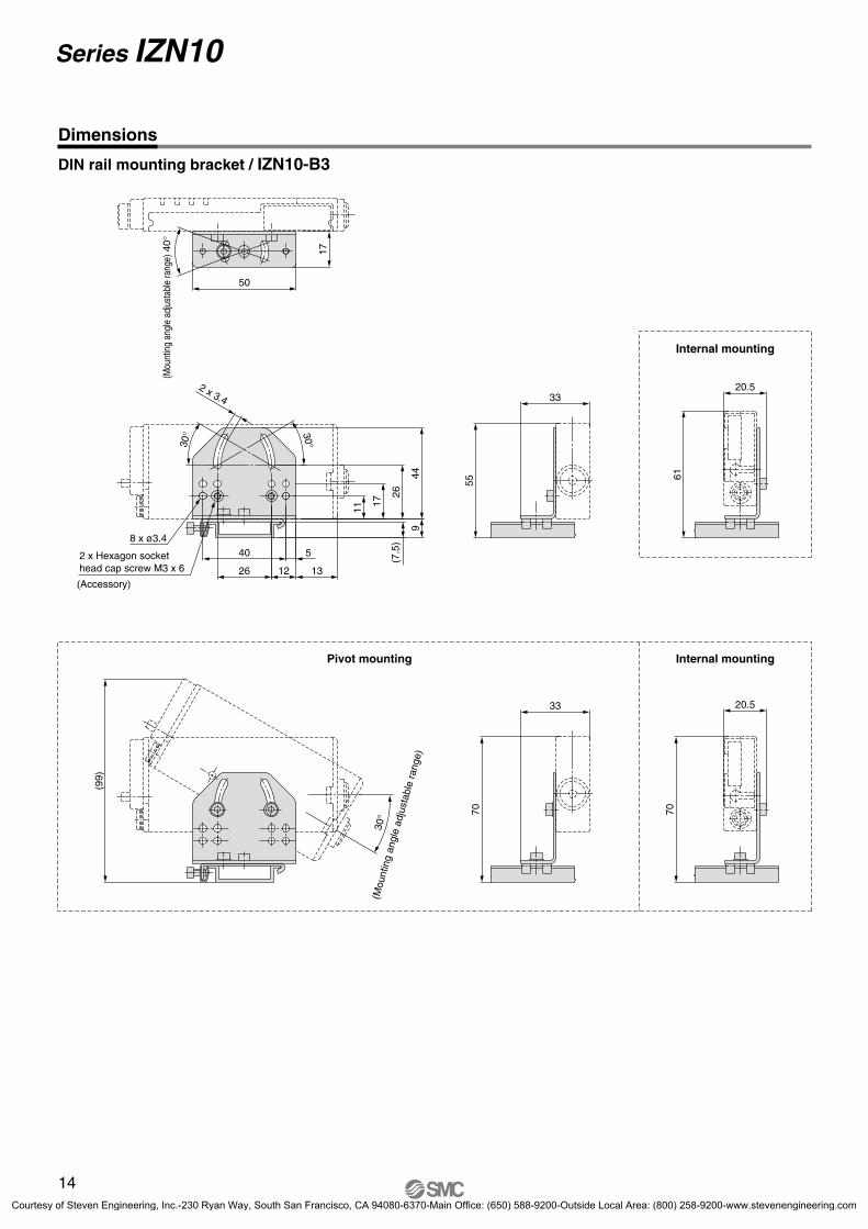
Dimensions
DIN rail mounting bracket / IZN10-B3
70
20.533
70
(99)
61
20.5
55
33
Internal mountingPivot mounting
Internal mounting
17
50
(Mou
ntin
g an
gle
adju
stab
le ra
nge)
40°
9
(7.5
)2 x 3.4
30°30°
44
26
17
11
26 12 13
40 5
(Accessory)
2 x Hexagon sockethead cap screw M3 x 6
8 x ø3.4
30°
(Mou
ntin
g an
gle
adju
stab
le r
ange
)
14
Series IZN10
Courtesy of Steven Engineering, Inc.-230 Ryan Way, South San Francisco, CA 94080-6370-Main Office: (650) 588-9200-Outside Local Area: (800) 258-9200-www.stevenengineering.com

15Courtesy of Steven Engineering, Inc.-230 Ryan Way, South San Francisco, CA 94080-6370-Main Office: (650) 588-9200-Outside Local Area: (800) 258-9200-www.stevenengineering.com

Safety InstructionsThese safety instructions are intended to prevent hazardous situations and/or equipment damage.These instructions indicate the level of potential hazard with the labels of “Caution,” “Warning” or “Danger.” They are all important notes for safety and must be followed in addition to International Standards (ISO/IEC), Japan Industrial Standards (JIS)∗1) and other safety regulations∗2).
∗1) ISO 4414: Pneumatic fluid power -- General rules relating to systems.ISO 4413: Hydraulic fluid power -- General rules relating to systems.IEC 60204-1: Safety of machinery -- Electrical equipment of machines. (Part 1: General requirements)ISO 10218-1992: Manipulating industrial robots -Safety.JIS B 8370: General rules for pneumatic equipment.JIS B 8361: General rules for hydraulic equipment.JIS B 9960-1: Safety of machinery - Electrical equipment of machines. (Part 1: General requirements)JIS B 8433-1993: Manipulating industrial robots - Safety.etc.
∗2) Labor Safety and Sanitation Law, etc.
1. The compatibility of the product is the responsibility of the person who designs the equipment or decides its specifications. Since the product specified here is used under various operating conditions, its compatibility with specific equipment must be decided by the person who designs the equipment or decides its specifications based on necessary analysis and test results. The expected performance and safety assurance of the equipment will be the responsibility of the person who has determined its compatibility with the product. This person should also continuously review all specifications of the product referring to its latest catalog information, with a view to giving due consideration to any possibility of equipment failure when configuring the equipment.
2. Only personnel with appropriate training should operate machinery and equipment.The product specified here may become unsafe if handled incorrectly. The assembly, operation and maintenance of machines or equipment including our products must be performed by an operator who is appropriately trained and experienced.
3. Do not service or attempt to remove product and machinery/equipment until safety is confirmed.1. The inspection and maintenance of machinery/equipment should only be performed after measures to prevent falling or
runaway of the driven objects have been confirmed. 2. When the product is to be removed, confirm that the safety measures as mentioned above are implemented and the power
from any appropriate source is cut, and read and understand the specific product precautions of all relevant products carefully.
3. Before machinery/equipment is restarted, take measures to prevent unexpected operation and malfunction.
4. Contact SMC beforehand and take special consideration of safety measures if the product is to be used in any of the following conditions.
1. Conditions and environments outside of the given specifications, or use outdoors or in a place exposed to direct sunlight.2. Installation on equipment in conjunction with atomic energy, railways, air navigation, space, shipping, vehicles, military,
medical treatment, combustion and recreation, or equipment in contact with food and beverages, emergency stop circuits, clutch and brake circuits in press applications, safety equipment or other applications unsuitable for the standard specifications described in the product catalog.
3. An application which could have negative effects on people, property, or animals requiring special safety analysis. 4. Use in an interlock circuit, which requires the provision of double interlock for possible failure by using a mechanical
protective function, and periodical checks to confirm proper operation.
Warning
Caution: Operator error could result in injury or equipment damage.
Operator error could result in serious injury or loss of life.
In extreme conditions, there is a possibility of serious injury or loss of life.
Warning: Danger :
Back page 1Courtesy of Steven Engineering, Inc.-230 Ryan Way, South San Francisco, CA 94080-6370-Main Office: (650) 588-9200-Outside Local Area: (800) 258-9200-www.stevenengineering.com
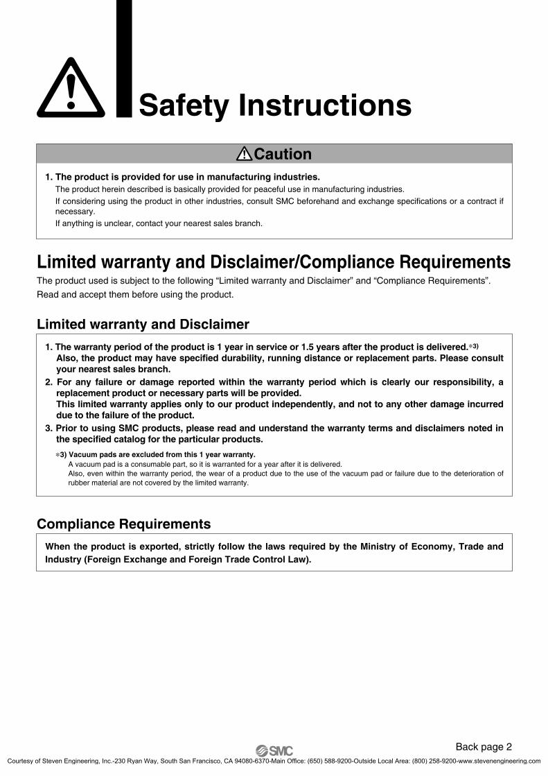
Safety Instructions
Limited warranty and Disclaimer/Compliance RequirementsThe product used is subject to the following “Limited warranty and Disclaimer” and “Compliance Requirements”.
Read and accept them before using the product.
1. The product is provided for use in manufacturing industries.The product herein described is basically provided for peaceful use in manufacturing industries. If considering using the product in other industries, consult SMC beforehand and exchange specifications or a contract if necessary.If anything is unclear, contact your nearest sales branch.
Caution
Limited warranty and Disclaimer
1. The warranty period of the product is 1 year in service or 1.5 years after the product is delivered.∗3)
Also, the product may have specified durability, running distance or replacement parts. Please consult your nearest sales branch.
2. For any failure or damage reported within the warranty period which is clearly our responsibility, a replacement product or necessary parts will be provided. This limited warranty applies only to our product independently, and not to any other damage incurred due to the failure of the product.
3. Prior to using SMC products, please read and understand the warranty terms and disclaimers noted in the specified catalog for the particular products.
∗3) Vacuum pads are excluded from this 1 year warranty. A vacuum pad is a consumable part, so it is warranted for a year after it is delivered. Also, even within the warranty period, the wear of a product due to the use of the vacuum pad or failure due to the deterioration of rubber material are not covered by the limited warranty.
Compliance Requirements
When the product is exported, strictly follow the laws required by the Ministry of Economy, Trade and Industry (Foreign Exchange and Foreign Trade Control Law).
Back page 2Courtesy of Steven Engineering, Inc.-230 Ryan Way, South San Francisco, CA 94080-6370-Main Office: (650) 588-9200-Outside Local Area: (800) 258-9200-www.stevenengineering.com
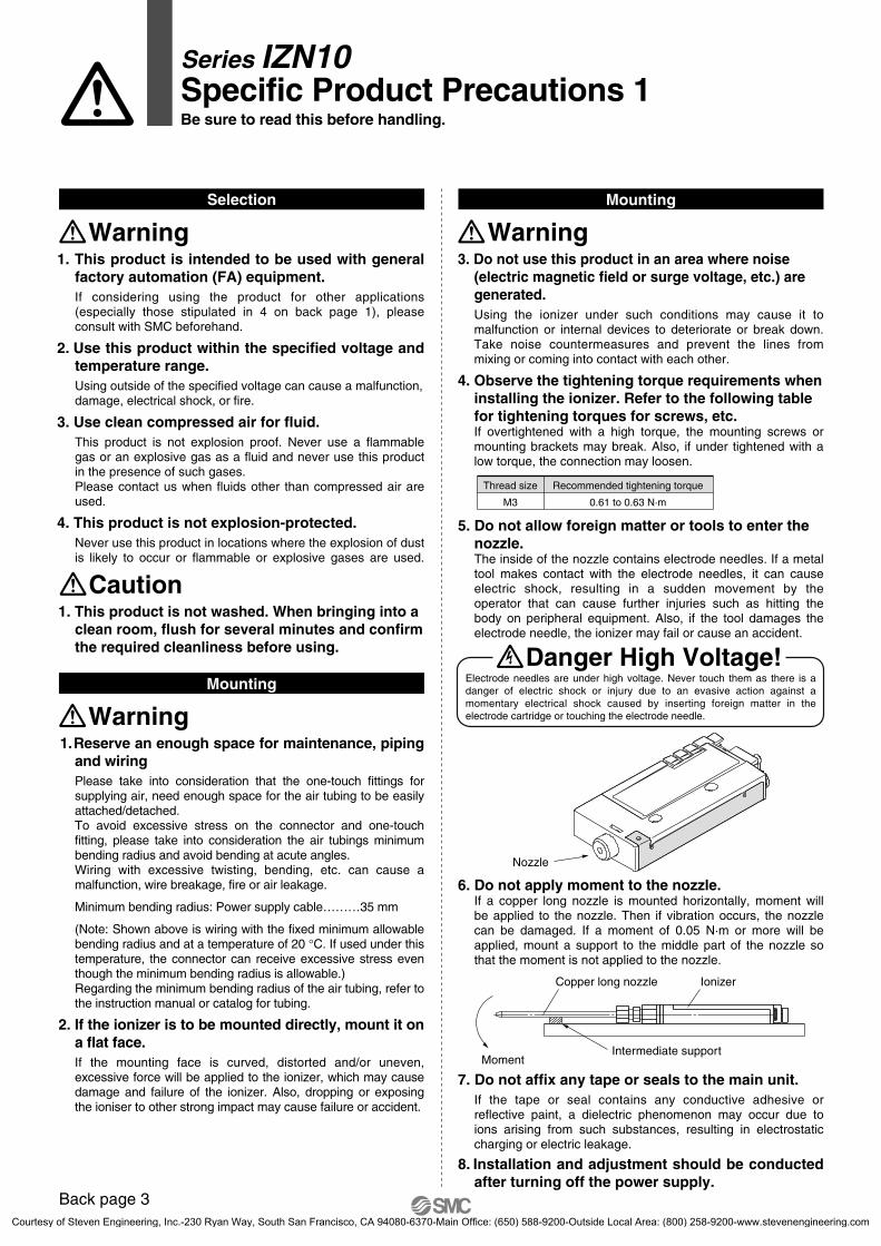
Mounting
5. Do not allow foreign matter or tools to enter the nozzle.The inside of the nozzle contains electrode needles. If a metal tool makes contact with the electrode needles, it can cause electric shock, resulting in a sudden movement by the operator that can cause further injuries such as hitting the body on peripheral equipment. Also, if the tool damages the electrode needle, the ionizer may fail or cause an accident.
7. Do not affix any tape or seals to the main unit.If the tape or seal contains any conductive adhesive or reflective paint, a dielectric phenomenon may occur due to ions arising from such substances, resulting in electrostatic charging or electric leakage.
8. Installation and adjustment should be conducted after turning off the power supply.
6. Do not apply moment to the nozzle.If a copper long nozzle is mounted horizontally, moment will be applied to the nozzle. Then if vibration occurs, the nozzle can be damaged. If a moment of 0.05 N·m or more will be applied, mount a support to the middle part of the nozzle so that the moment is not applied to the nozzle.
Recommended tightening torque
0.61 to 0.63 N·m
Thread size
M3
Nozzle
Intermediate support
Copper long nozzle Ionizer
Moment
Electrode needles are under high voltage. Never touch them as there is a danger of electric shock or injury due to an evasive action against a momentary electrical shock caused by inserting foreign matter in the electrode cartridge or touching the electrode needle.
Danger High Voltage!
Back page 3
Specific Product Precautions 1Be sure to read this before handling.
Series IZN10
1. This product is intended to be used with general factory automation (FA) equipment.If considering using the product for other applications (especially those stipulated in 4 on back page 1), please consult with SMC beforehand.
2. Use this product within the specified voltage and temperature range.Using outside of the specified voltage can cause a malfunction, damage, electrical shock, or fire.
3. Use clean compressed air for fluid.This product is not explosion proof. Never use a flammable gas or an explosive gas as a fluid and never use this product in the presence of such gases.Please contact us when fluids other than compressed air are used.
4. This product is not explosion-protected.Never use this product in locations where the explosion of dust is likely to occur or flammable or explosive gases are used.
Selection
Warning
1. This product is not washed. When bringing into a clean room, flush for several minutes and confirm the required cleanliness before using.
Caution
Mounting
Warning1. Reserve an enough space for maintenance, piping
and wiringPlease take into consideration that the one-touch fittings for supplying air, need enough space for the air tubing to be easily attached/detached.To avoid excessive stress on the connector and one-touch fitting, please take into consideration the air tubings minimum bending radius and avoid bending at acute angles.Wiring with excessive twisting, bending, etc. can cause a malfunction, wire breakage, fire or air leakage.
Minimum bending radius: Power supply cable………35 mm
(Note: Shown above is wiring with the fixed minimum allowable bending radius and at a temperature of 20 °C. If used under this temperature, the connector can receive excessive stress even though the minimum bending radius is allowable.)Regarding the minimum bending radius of the air tubing, refer to the instruction manual or catalog for tubing.
2. If the ionizer is to be mounted directly, mount it on a flat face.If the mounting face is curved, distorted and/or uneven, excessive force will be applied to the ionizer, which may cause damage and failure of the ionizer. Also, dropping or exposing the ioniser to other strong impact may cause failure or accident.
Mounting
Warning3. Do not use this product in an area where noise
(electric magnetic field or surge voltage, etc.) are generated.Using the ionizer under such conditions may cause it to malfunction or internal devices to deteriorate or break down. Take noise countermeasures and prevent the lines from mixing or coming into contact with each other.
4. Observe the tightening torque requirements when installing the ionizer. Refer to the following table for tightening torques for screws, etc.If overtightened with a high torque, the mounting screws or mounting brackets may break. Also, if under tightened with a low torque, the connection may loosen.
Courtesy of Steven Engineering, Inc.-230 Ryan Way, South San Francisco, CA 94080-6370-Main Office: (650) 588-9200-Outside Local Area: (800) 258-9200-www.stevenengineering.com

Specific Product Precautions 2Be sure to read this before handling.
Series IZN10
2. Always use a UL listed Class 2 output 24 VDC power supply.
3. Be sure to provide Class D grounding in order to maintain product performance. If such grounding is not provided, not only may static electricity removal capability be disrupted but electric shocks may also result and the ionizer or power supply may break down.
4. Be sure to turn off the power supply before wiring (including attachment/detachment of the connector).
5. When applying the power supply, pay special attention to the wiring and/or surrounding environment until the safety is confirmed.
6. Do not connect or remove any connectors including the power supply, while power is being supplied. Otherwise, the ionizer may malfunction.
7. If the power line and high pressure line are routed together, this product may malfunction due to noise. Therefore, use a separate wiring route for this product.
8. Be sure to confirm there are no wiring errors before starting this product. Incorrect wiring will lead to damage or malfucntion to the product.
9. Flush the piping before using.Before using this product, exercise caution to prevent particles, water drop, or oil from entering the piping.
2. Take preventative measures against ozone.Equipment used around the ionizer should have ozone-prevention measures.Also, regularly check that there is no deterioration due toozone.
3. The ionizer cannot be used without air purge.Without air purge, not only will the ionizer be unable to eliminate charge, but also the internal ozone condensation will increase and adversely affect the ionizer and peripheral equipment. Therefore, be sure to perform air purge when energizing the ionizer.
4. Observe the fluid and ambient temperature range.Fluid and ambient temperature ranges are 0 to 55°C for the ionizer. Do not use the ionizer in locations subject to sudden temperature changes even if the ambient temperature range is within the specified limits, as condensation may result.
5. Environments to avoidAvoid using and storing this product in the following environments since they may cause damage to this product.
a) Avoid using in a place that exceeds an ambient temperature range of 0 to 55°C.
b) Avoid using in a place that exceeds an ambient humidity range of 35 to 65% Rh.
c) Avoid using in a place where condensation occurs due to a drastic temperature change.
d) Avoid using in a place in the presence of corrosive or explosive gas or where there is a volatile combustible.
e) Avoid using in an atmosphere where there are particles, conductive iron powders, oil mist, salt, solvent, blown dust, cutting oil (water, liquid), etc.
f) Avoid using in a place where ventilated air from an air conditioner is directly applied to the product.
g) Avoid using in a closed place without ventilation.
h) Avoid using in direct sunlight or radiated heat.
I) Avoid using in a place where there is a strong magnetic noise (strong electric field, strong magnetic field, or surge).
j) Avoid using in a place where static electricity is discharged to the main body.
k) Avoid using in a place where a strong high frequency occurs.
l) Avoid using in a place where this product is likely to be damaged by lightning.
m) Avoid using in a place where direct vibration or shock is applied to the main body.
n) Avoid using in a place where there is a force large enough to deform this product or weight is applied to the product.
6. Do not use an air containing mist or dust.The air containing mist or dust will cause the performance to decrease and shorten the maintenance cycle. Supply clean compressed air by using an air dryer (IDF series), air filter (AF/AFF series), and mist separator (AFM/AM series)
7. The ionizer is not designed to withstand lightning.
1. Do not use this product in an enclosed space.This product utilizes a corona discharge phenomenon. Do not use the product in an enclosed space as ozone and nitrogen oxides exist in such places, even though in marginal quantities.Also, ozone condensation can increase if used in an enclosed space, which can affect the human body, so ventilation is necessary. Even if ventilation is secured, the use of two more ionizers in a narrow space can increase ozone condensation. Therefore, check that ozone condensation is not more than a standard value of 0.1 ppm in the operating environment while the ionzier is in operation.
1. Before wiring confirm if the power supply voltage is enough and that it is within the specifications before wiring.
WarningWiring / Piping
WarningOperating Environment / Storage Environment
WarningOperating Environment / Storage Environment
Back page 4Courtesy of Steven Engineering, Inc.-230 Ryan Way, South San Francisco, CA 94080-6370-Main Office: (650) 588-9200-Outside Local Area: (800) 258-9200-www.stevenengineering.com

Specific Product Precautions 3Be sure to read this before handling.
Series IZN10
1. Periodically (for example, every two weeks) inspect the ionizer and clean the electrode needles.Conduct a regular maintenance to see if the product is run having a disorder.Maintenance should be conducted by a fully knowledgeable and experienced person about the equipment. Using for long periods of time will lower the static electricity eliminating performance, if particles attach to the electrode pin. When the maintenance signal LED lights up, clean the electrode needle.Replace the electrode cartridge, if the pins are worn and the static electricity eliminating performance does not return even after being cleaned.
Maintenance
Warning
This product contains a high voltage generation circuit. When performing maintenance inspection, be sure to confirm that the power supply to the ionizer is turned off. Never disassemble or modify the ionizer, as this may not only impair the product’s functionality but could cause an electric shock or electric leakage.
Danger High Voltage!
2. The tube and fitting must be treated as consumable parts.The tube and fitting that are connected to the female piping ports of the ionizer can deteriorate due to ozone and need to be replaced regularly or use an ozone-resistant type.
3. When cleaning the electrode pin or replacing the electrode cartridge, be sure to turn off the power supply to the main body. Touching an electrode needle when it is electrified may result in electric shock or other accidents.
4. Do not disassemble or modify this product.Otherwise, an electrical shock, damage and/or a fire may occur. Also, the disassembled or modified products may not achieve the performances guaranteed in the specifications, and excercise caution because the product will not be warrantied.
5. Do not operate this product with wet hands.Otherwise, an electrical shock or accident may occur.
1. Do not drop, bump or apply excessive impact (10 G or more) while handling.Even though it does not appear to be damaged, the internal parts may be damaged and cause a malfunction.
2. When mounting/dismounting the cable, use your finger to pinch the claw of the modular plug, then attach/detach it correctly. Otherwise, modular plug mounting section may be damaged and cause a disorder.
Handling
Warning
Back page 5Courtesy of Steven Engineering, Inc.-230 Ryan Way, South San Francisco, CA 94080-6370-Main Office: (650) 588-9200-Outside Local Area: (800) 258-9200-www.stevenengineering.com

Courtesy of Steven Engineering, Inc.-230 Ryan Way, South San Francisco, CA 94080-6370-Main Office: (650) 588-9200-Outside Local Area: (800) 258-9200-www.stevenengineering.com

CAT.ES100-65
CAT.ES100-69
CAT.ES100-68
Related Products
Ionizer Series IZS31
Electrostatic Sensor Series IZD10 / Electrostatic Sensor Monitor Series IZE11Electrostatic Sensor Series IZD10The importance of the static electric control is put on confirming the “actual status”. Potential measurement: ± 20 kV (detected at a 50 mm distance)
± 0.4 kV (detected at a 25 mm distance) Detects the electrostatic potential and outputs in an analog voltage
• Output voltage: 1 to 5 V (Output impedance: Approx. 100 )
Possible to measure electrostatic potential
Static electricityelimination time 0.3 secondsThe speed of static electricity elimination has beenincreased by optimization of a feedback sensor and shape of a nozzle.Conditions / Static buildup decreased from 1000 V to 100 V
Discharged object: Charged plate monitor (150 mm x 150 mm, capacitance 20 pF)Installation distance: 200 mm (Tungsten electrode with air purge)
Auto-balance sensorMeasures the ion balance.
Feedback sensor Detects the polarity of a discharged object
and measures the charged voltage.
Electrostatic Sensor Monitor Series IZE11 Output: Switch output x 2 + Analog output (1 to 5 V, 4 to 20 mA) Minimum unit setting: 0.001 kV (at ±0.4 kV), 0.1 kV (at ±20 kV) Display accuracy: ±0.5% F.S. ±1 digit or less Detection distance correction function
(adjustable in 1 mm increments)
Range switching supports two sensors. (±0.4 kV, ±20 kV)
Handheld Electrostatic Meter Series IZH10The importance of the static electric control is put on confirming the “actual status”.Easy-to-use handheld electrostatic meter Measuring range: ±20.0 kV Minimum display unit: 0.1 kV (±1.0 to ±20.0 kV)
0.01 kV (0 to ±0.99 kV)
Compact & Lightweight: 85 g(excluding dry cell batteries)
Backlight for reading in the dark LOW battery indicator Peak/Bottom display function Zero-out function Auto power-off functionCourtesy of Steven Engineering, Inc.-230 Ryan Way, South San Francisco, CA 94080-6370-Main Office: (650) 588-9200-Outside Local Area: (800) 258-9200-www.stevenengineering.com

4
9
6 7 8
5
SMC can provide all the equipment required to supply air to the ionizer. Consider the equipment below not only for providing an “opportunity to decrease maintenance” and “preventing damage” but also for an “energy-saving countermeasure”.
Recommended pneumatic circuit diagram
Air Dryer / Series IDFDecreases the dew point of compressed air.Limits moisture generation which can lead todamage.
Digital Flow Switch / Series PF2ADecreases the air consumption by flowcontrol.
2-Color Display Digital Flow Switch / Series PFM Regulator / Series ARDecreases the air consumption by setting to an appropriate pressure.
Digital Pressure Switch / Series ISE30The pressure control prevents the ability of static electricity removal from being reducedin accordance with the reduction of air pressure.
2 Port Solenoid Valve / Series VX Restrictor / Series AS-X214Regulates to the appropriate air volumedepending upon the installation condition.Decreases the air consumption.
1
1 2 3 4 5 6 7 8 9
2 3Air Filter / Series AFEliminates solid foreign matters such aspowder particles in the compressed air.
Mist Separator / Series AFMEliminates oil mist which is difficult toeliminate with an air filter.
Clean Air Filter / Series SFDBuilt-in capillary elementNominal filtration rating: 0.01 µmAdopted hollow fiber elements with over 99.99% filtering efficiency do not contaminate workpieces.
Reg
Courtesy of Steven Engineering, Inc.-230 Ryan Way, South San Francisco, CA 94080-6370-Main Office: (650) 588-9200-Outside Local Area: (800) 258-9200-www.stevenengineering.com
SMC Static Electricity Prevention Equipment
• Examples of static electricity-related problems• Antistatic equipment• Static electricity elimination equipment• Measurement equipment• Technical data
For the details of this equipment,refer to “Static Electricity PreventionEquipment” pamphlet.
Publishing contents
P-E06-15
Akihabara UDX 15F, 4-14-1, Sotokanda, Chiyoda-ku, Tokyo 101-0021, JAPANPhone: 03-5207-8249 Fax: 03-5298-5362URL http://www.smcworld.com© 2008 SMC Corporation All Rights Reserved
Specifications are subject to change without prior notice and any obligation on the part of the manufacturer.
1st printing MP printing MP 13500KS Printed in Japan.D-KS
This catalog is printed on recycled paper with concern for the global environment.Courtesy of Steven Engineering, Inc.-230 Ryan Way, South San Francisco, CA 94080-6370-Main Office: (650) 588-9200-Outside Local Area: (800) 258-9200-www.stevenengineering.com