NEW POLYTECHNIC, KOLHAPUR - NPKautonpkauto.com/oldweb/data/notes/second/4g/hpe/Ch.3 Air Compressor -...
20
NEW POLYTECHNIC, KOLHAPUR CH.3 AIR COMPRESSORS /18 MARKS HPE/17407/AE4G R.K.Yadav/Automobile Engg Dept/New Polytechnic Kolhapur. Page 1 Content: ____________________________________________________________________ 3.1 Classification of air compressor - Construction and working of single stage and two stage reciprocating air compressors with P-V. diagram. Necessity of multi- staging and inter cooling. Construction and working of rotary compressors i) Centrifugal compressor ii) Axial flow compressor iii) Screw compressor, Comparison of various compressors. 3.2 Air compressor terminology like i) Free air delivered, ii) Capacity of Compressor, iii) Piston displacement, iv) I. P., v) B. P., vi) Volumetric efficiency, vii) Isothermal efficiency, viii) Overall Isothermal or Compressor efficiency. (Only definitions), Factors affecting volumetric Efficiency of reciprocating air compressors. 3.3 Applications of compressed air: construction and working of i) Rock drill, ii) pneumatic torque wrench ____________________________________________________________________ AIR COMPRESSOR : 1) It is a power absorbing or energy convergent device used to raise the pressure of air by reducing its volume. 2) It is of two types i) Reciprocating and ii) Rotary compressors. Normally Reciprocating compressor with inlet and exhaust valves, and rotary with inlet and exhaust port. 3) Following fig shows energy flow from prime-mover to compressor.
Transcript of NEW POLYTECHNIC, KOLHAPUR - NPKautonpkauto.com/oldweb/data/notes/second/4g/hpe/Ch.3 Air Compressor -...

NEW P
OLYTECHNIC
, KOLH
APUR
CH.3 AIR COMPRESSORS /18 MARKS HPE/17407/AE4G
R.K.Yadav/Automobile Engg Dept/New Polytechnic Kolhapur. Page 1
Content:____________________________________________________________________
3.1 Classification of air compressor - Construction and working of single stage andtwo stage reciprocating air compressors with P-V. diagram. Necessity of multi-staging and inter cooling. Construction and working of rotary compressors i)Centrifugal compressor ii) Axial flow compressor iii) Screw compressor, Comparisonof various compressors.
3.2 Air compressor terminology like i) Free air delivered, ii) Capacity of Compressor,iii) Piston displacement, iv) I. P., v) B. P., vi) Volumetric efficiency, vii) Isothermalefficiency, viii) Overall Isothermal or Compressor efficiency. (Only definitions),Factors affecting volumetric Efficiency of reciprocating air compressors.
3.3 Applications of compressed air: construction and working of i) Rock drill, ii)pneumatic torque wrench____________________________________________________________________
AIR COMPRESSOR :
1) It is a power absorbing or energy convergent device used to raise the pressure ofair by reducing its volume.
2) It is of two types i) Reciprocating and ii) Rotary compressors.
Normally Reciprocating compressor with inlet and exhaust valves, and rotary withinlet and exhaust port.
3) Following fig shows energy flow from prime-mover to compressor.

NEW P
OLYTECHNIC
, KOLH
APUR
CH.3 AIR COMPRESSORS /18 MARKS HPE/17407/AE4G
R.K.Yadav/Automobile Engg Dept/New Polytechnic Kolhapur. Page 2
Here Prime-mover like steam engine, I.C. engine, electric motor are needed to runcompressor.
CLASSIFICATION OF AIR COMPRESSOR :
OR
There are main two categories of air compressors i) Reciprocating ii) Rotarycompressor. But according to Geometry and operational characteristics featuresfollowings are some types like-
A) According to action :i) Single acting reciprocating air compressor.ii) Double acting reciprocating air compressor.
B) According to stages :i) Single stageii) Double stageiii) Multi stage
C) According to position of cylinder :i) Verticalii) Horizontal
D) According to drive compressor :i) Motor drivenii) Engine driveniii) Steam/Gas turbine driven
E) According to cooling medium :

NEW P
OLYTECHNIC
, KOLH
APUR
CH.3 AIR COMPRESSORS /18 MARKS HPE/17407/AE4G
R.K.Yadav/Automobile Engg Dept/New Polytechnic Kolhapur. Page 3
i) Air cooledii) Oil coolediii) Water cooled
F) According to portability condition :i) Portable compressorii) Stationery compressor
G) According to type of displacement :i) Positive displacement
e.g. Roots blower, vane type, mono screw; twin screwReciprocating – piston type & diaphragm type.
ii) Non-positive displacemente.g. Centrifugal (or) radial flow & axial flow.
AIR COMPRESSOR TERMINOLOGY :
1) Single acting compressor :
Here suction, compression & delivery of air takes place on one side of pistononly.
Here we get one delivery stroke after one complete revolution of crank shaft.
2) Double acting compressor :
Here suction, compression and delivery of air takes place on both sides ofpiston.
Here we get two delivery stroke after one complete revolution of crank shaft.
3) Single stage compressor :
In this compression of air from initial pressure to final pressure is carried outin one cylinder only.
4) Multi stage compressor :
When compression of air from initial pressure to final pressure is carried outin more than one cylinder.
5) Compression ratio (or) Pressure ratio (Pd/Pi)
It is ratio of discharge pressure to the inlet pressure.
Here discharge pressure is always more than inlet pressure. So value of C.R.ismore than one.
6) Inlet pressure :
It is the absolute pressure of air at the inlet of compressor.
7) Discharge pressure :
It is the absolute pressure of air at the outlet of compressor.

NEW P
OLYTECHNIC
, KOLH
APUR
CH.3 AIR COMPRESSORS /18 MARKS HPE/17407/AE4G
R.K.Yadav/Automobile Engg Dept/New Polytechnic Kolhapur. Page 4
8) Swept volume:(or) (Displacement of compressor/ Piston)
It is the volume of air sucked by compressor during its suction stroke which isexpressed as-
Vs = IIx D2 X L4
Where : D = Diameter of cylinder bore.
L = Length of piston stroke.
9) Capacity of compressor :
It is the volume of air delivered by compressor and is expressed in m3/min.(or) m3/sec.
10) Free air delivery : (F.A.D.)
It is the volume of air delivered under the condition of temperature andpressure existing at compressor intake. When free air conditions are notgiven, these are taken as S.T.P. condition i.e. pressure 1.0135 bar &temperature 15oC.
11) Volumetric efficiency :
It is the ratio of volume of free air delivered per stroke to the displacement ofcompressor.
12) Isothermal efficiency / compressor efficiency :
It is the ratio of isothermal work to actual work to run the compressor.
13) Isothermal efficiency /compressor efficiency :
It is the ratio of work (or) power required compressing the air isothermally tothe actual work required to compress the air for the same pressure ratio.
14) Indicated power (I.P.) (or) Air power :
It is the ratio of polytropic work into speed of compressor to 60.
I.P. = W X Nw Watts60
15) Brake power (B.P.) (or) Shaft power :
It is the power required to drive the compressor (or) power delivered to theshaft of compressor.

NEW P
OLYTECHNIC
, KOLH
APUR
CH.3 AIR COMPRESSORS /18 MARKS HPE/17407/AE4G
R.K.Yadav/Automobile Engg Dept/New Polytechnic Kolhapur. Page 5
RECIPROCATING AIR COMPRESSOR :
We know that in reciprocating air compressor pressure of air is increased inits cylinder with the help of moving piston.
Single Stage, Single acting Reciprocating Air compressor :
Single stage reciprocating air compressor consist of the following main components.
1) Suction Valve, 2) Delivery Valve, 3) Piston Cylinder arrangement etc.
In single stage reciprocating air compressor without clearance volume thereare main three strokes-i) Suction, ii) Compression & iii) Delivery.
While with clearance volume there are four strokes i) Expansion ii) suction iii)compression iv) Delivery.
When piston moves from T.D.C. to B.D.C.,Pressure inside the cylinder fallsbelow an atmospheric pressure.
Due to this pressure difference suction valve gets opened and air is suckedinto the cylinder.
Now the piston moves upwards from B.D.C. to T.D.C. pressure inside thecylinder goes on increasing till it reaches the discharge pressure. At this stagedelivery valve gets opened and air is delivered to container. When compressionstroke is taking place both suction and delivery valve are closed.

NEW P
OLYTECHNIC
, KOLH
APUR
CH.3 AIR COMPRESSORS /18 MARKS HPE/17407/AE4G
R.K.Yadav/Automobile Engg Dept/New Polytechnic Kolhapur. Page 6
This process is repeated continuously. When pressure of air increasesautomatically volume of air decreases and temperature of air increases.
In single stage, single acting, reciprocating air compressor, suction,compression and delivery of air takes place in two strokes of piston (or) onerevolution of crankshaft.
P-V diagram for working of single stage, single acting reciprocating air compressorwithout clearance volume are given below :
4-1– Represents suction of air at pressure p1.During this operation inlet valveremains open.
1-2 -Represents the compression of air polytropically. During this operation ,inletand delivering valves remain closed.
2-3 –Represents the discharge of air to the receiver at a pressure p2.The outletvalves remain open during this period.

NEW P
OLYTECHNIC
, KOLH
APUR
CH.3 AIR COMPRESSORS /18 MARKS HPE/17407/AE4G
R.K.Yadav/Automobile Engg Dept/New Polytechnic Kolhapur. Page 7
P-V diagram for working of single stage, single acting reciprocating air compressorwith clearance volume are given below :
Here at the end of delivery stroke, the high pressure air is left in the clearancevolume and the suction for the second cycle starts only when the air pressurefalls to the atmospheric pressure. This is represented by expansion curve 3-4Assuming the compression and expansion of the air follow the same law.

NEW P
OLYTECHNIC
, KOLH
APUR
CH.3 AIR COMPRESSORS /18 MARKS HPE/17407/AE4G
R.K.Yadav/Automobile Engg Dept/New Polytechnic Kolhapur. Page 8
Two Stage Reciprocating air compressor :
In above fig. shows two stage reciprocating air compressor with water cooledintercooler.
1) First of all fresh air is sucked from atmosphere in low pressure (L.P.) cylinderduring its suction stroke at inlet pressure p1 and Temperature t1.
2) The air after compression in L.P. cylinder (1st stage) from 1 to 2 is deliveredto intercooler at pressure p2 and Temperature t2.
3) Now air is cooled in intercooler from 2 to 3 at constant pressure p2 and fromTemperature t2 to t3.
4) After that air is sucked in high pressure (H.P.) cylinder during its suctionstroke.
5) Finally air after further compression in H.P. cylinder (i.e. second stage) from 3to 4 is delivered by the compressor at pressure p3 & Temperature t4.
6) P-V diagram for two stages reciprocating compressor with intercooler is givenbelow :

NEW P
OLYTECHNIC
, KOLH
APUR
CH.3 AIR COMPRESSORS /18 MARKS HPE/17407/AE4G
R.K.Yadav/Automobile Engg Dept/New Polytechnic Kolhapur. Page 9
PV diagram for Two stage reciprocating air compressor.
Necessity of Multi-staging Compression :
We know, sometimes we required air at high pressure. In this case if we usesingle stage compression for producing high pressure air then it shows followingdrawbacks.
1) The size of cylinder should be too large.2) Due to compression there is rise in temperature of air, so it is difficult to
reject heat from air in small time available during compression.3) At the end of compression temperature of air is too high. It may heat-up the
cylinder head (or) burn the lubricating oil.4) So, to overcome above difficulties two (or) more than two cylinders are
provided in series with inter cooling arrangement between them.
Advantages of Multistage Compressor :
1) It improves volumetric efficiency.2) It reduces leakage losses considerably.3) Work required per Kg. of air is reduced.4) Size of two cylinders may be adjusted to suit volume and pressure of air.5) It gives uniform torque so smaller size of flywheel is required.

NEW P
OLYTECHNIC
, KOLH
APUR
CH.3 AIR COMPRESSORS /18 MARKS HPE/17407/AE4G
R.K.Yadav/Automobile Engg Dept/New Polytechnic Kolhapur. Page 10
6) It provides effective lubrication due to lower temperature range.7) Reduces power required to drive the compressor8) It reduces cost of compressor.9) Lesser vibration and less maintenance.
Necessity of Inter cooling :
When we use multistage compression there is necessity of intercoolerbetween stages.
We know, air is sucked in first cylinder then compress it after compressiontemperature of air increases.
If it does not pass through intercooler and directly send to second stage because ofincrease in temperature volume of air increases. So amount of air taken in cylinderdecreases so atomically pressure is decreased, so volumetric efficiency decreases.
If Intercooler is placed between cylinders then temperature of air decreases and it ismaintained at temperature of atmospheric temperature without decreasing pressureof air.
So volumetric efficiency increases and input of compressor decreases (i.e. electricityused to drive compressor).
PV diagram for multi stage air compressor.

NEW P
OLYTECHNIC
, KOLH
APUR
CH.3 AIR COMPRESSORS /18 MARKS HPE/17407/AE4G
R.K.Yadav/Automobile Engg Dept/New Polytechnic Kolhapur. Page 11
Factors Affecting Volumetric Efficiency of reciprocating air compressor :
1) Clearance volume increases, volumetric efficiency decreases.2) Piston ring leakage.3) If the speed of rotation is high, then charge of air taken in is less which
decreases efficiency.4) Restricted passage and leakage of inlet valves affects on volumetric efficiency.5) Obstruction at inlet valves.6) If fresh air comes in contact with hot valves it gets expended; which
decreases the charge taken in therefore volumetric efficiency decreases.7) Overheating of air by contact with hot cylinder wall.
8) Inertia effect of air in suction pipe.
Rotary air compressor :
In rotary air compressor the air is entrapped between two sets of engagingsurface and pressure of air is increased by squeezing action.
Centrifugal air Compressor :
In above figure shows simplest form of centrifugal compressor which consist of rotor(ie. Impeller) ,eye or main shaft, diffuser, casing.
To impeller number of curved vanes are fitted symmetrically. The rotor rotates in anair tight volute casing with inlet port (ie. through impeller eye) and outlet port.
The casing of compressor is made by cast iron and designed in such away that,kinetic energy of air is converted into pressure energy Before it leaves the casing.
The mechanical energy is provided to rotor from external source. As the rotorrotates, it sucks air through its eye and increase its pressure due to centrifugal forceand forces the air to flow over diffuser (not shown in fig). The pressure of air isfurther increased during its flow over the diffuser.

NEW P
OLYTECHNIC
, KOLH
APUR
CH.3 AIR COMPRESSORS /18 MARKS HPE/17407/AE4G
R.K.Yadav/Automobile Engg Dept/New Polytechnic Kolhapur. Page 12
Finally, the air at a high pressure is delivered to receiver. The air enters theimpeller axially and leaves vanes radially.
Advantages of Centrifugal Compressor :1) Speed of compressor is high.2) It handles large volume of air.3) Free from vibrations and noise.4) It can be directly coupled to motor (or) prime mover.5) Efficiency is high.6) Only few parts required lubrication.
Disadvantages of Centrifugal Compressor :1) Multi stating is difficult.2) Pressure ratio is smaller.
Applications :
1) Used as air blower in smithy operation.2) In Turbocharger on vehicles.3) In furnace for combustion process.4) In saloon shop for hair drier.
Axial Flow Compressor :
Construction and working :
It consist of number of rotating blade rows fixed to rotating drum (i.e. rotor).The drum rotates inside in air tight casing to which fixed (stator) blade rows areshown in fig.

NEW P
OLYTECHNIC
, KOLH
APUR
CH.3 AIR COMPRESSORS /18 MARKS HPE/17407/AE4G
R.K.Yadav/Automobile Engg Dept/New Polytechnic Kolhapur. Page 13
The blades are made of aerofoil section to reduce the loss caused byturbulence and boundary separation.
The mechanical energy is provided to rotating shaft which rotates the drum(i.e. rotor).
The air enters from left side of compressor. As the rotor rotates air flowsthrough alternately arranged fixed and moving blade.
As air flows from one set of fixed and moving blade to another it getscompressed thus successive compression of air in all sets of fixed blade and movingblade; the air is delivered at high pressure at outlet.
Here total number of stages from : 5 to 15.
It handles air upto 30,00 m3/min.
Pressure rise in each stage is 10 -15%.
It is used in gas turbine power plant, in turbo jet, turbo prop engines.
Screw Compressor :
Construction and working :
It consist of two mutually engaged helical grooved rotors which are closed ina casing. Out of two rotors male rotor is driver and female rotor is driven.
Male rotor has four lobes and female rotor has six flutes. During rotationboth rotors are rotates exact opposite to each other (i.e. here driver in clockwisedirection and driven rotor in anticlockwise rotation) and air enters and takes placebetween male and female rotor.

NEW P
OLYTECHNIC
, KOLH
APUR
CH.3 AIR COMPRESSORS /18 MARKS HPE/17407/AE4G
R.K.Yadav/Automobile Engg Dept/New Polytechnic Kolhapur. Page 14
Here air traps and moves axially and radially with rotation of rotors and getscompressed due to volume reduction.
Then this air though outside from upward direction speed of rotor is differentdue to different number of lobes and flutes.
It handles 3.5 to 300 m3/min. and
Maximum pressure ratio of 20
This system requires lubrication. This compressor is noisy in operation used inrefrigeration industry.
Advantages of screw compressor :1) Uniform and continuous air flow is obtained.2) There is absence of suction and discharge valve eliminates pressure drop.3) Directly coupled to prime mover.4) It is perfectly balanced.5) It is simple; durable.6) High volumetric efficiency is obtained.
Comparison of Reciprocating & Rotary Air Compressor :
Reciprocating Compressor Rotary Compressor1 Delivery pressure is high as 1000
bar.1 Maximum delivery pressure is low
i.e. 10 bar.2 Maximum free air discharge is
about 300 m3/min.2 Maximum free air discharge is
high as 3000 m3/min.3 They are suitable for low discharge
and high pressure.3 They are suitable for high
discharge and low pressure.4 The speed of air compressor is low. 4 The speed of air compressor is
high.5 The size of compressor is large for
given discharge.5 The size of air compressor is small
for same discharge.6 The air supply is intermittent. 6 The air supply is continuous.7 The balancing is major problem. 7 There is no balancing problem.8 Air delivered is less clean as it
comes in contact with lubricatingoil.
8 Air delivered is more clean as itdoes not come in contact withlubricating oil.
9 e.g. Piston cylinder arrangement. 9 e.g. Centrifugal, Roots blower,screw Axial compressor type.
10 The lubricating system iscomplicated.
10 Lubricating system is simple.

NEW P
OLYTECHNIC
, KOLH
APUR
CH.3 AIR COMPRESSORS /18 MARKS HPE/17407/AE4G
R.K.Yadav/Automobile Engg Dept/New Polytechnic Kolhapur. Page 15
Centrifugal Compressor & Axial flow Compressor :
Centrifugal Compressor Axial flow Compressor1 The flow of air is perpendicular to
axis of compressor.1 The flow of air is parallel to axis of
compressor.2 It has low manufacturing and
running cost.2 It has high manufacturing and
running cost.3 It required low starting torque. 3 It required high starting torque.4 It is not suitable for multi stating. 4 It is suitable for multi stating.5 Eg. Air blower in furnace, In shops
for smithy operation, Inturbocharger, in hair dryer etc.
5 Eg. In gas turbine power plant, Inturbojet ,turbo prop engine.
Single Stage Compressor & Multi Stage Compressor :
Single Stage Compressor Multi Stage Compressor1 Compressor in which single cylinder
is used is called as single stagecompressor.
1 Compressor in which more thantwo cylinders are used then calledas multistage compressor.
2 No use of intercooler. 2 Intercooler is used in betn L.P. andH.P. stage.
3 More power is required to drivecompressor.
3 Less power is required to drivecompressor.
4 Required heavy and bigger cylinder. 4 Required small cylinder.5 Difficult in lubrication due to higher
working temperature.5 Lubrication is simple due to lower
working temperature.6 More leakage losses. 6 Leakage losses are reduced.7 Suitable for small capacity and low
delivery pressure.7 Suitable for large capacity and
high delivery pressure.8 Air is compressed from intake to
delivery pressure in one cylinder.8 Two (or) more than two cylinders
are used to compress air fromintake to delivery pressure.
Applications of Compressed air :
We know in day to day life compressed air is used for many purposes likeIndustrial, Commercial equipments. Some of applications are given below;
1) For operating power tools like pneumatic drills, riveters, Torque wrench,Hammer, rock drills.
2) In CNC-VMC shops for cleaning table, slots, jobs etc.
3) For clamping & de-clamping jobs.

NEW P
OLYTECHNIC
, KOLH
APUR
CH.3 AIR COMPRESSORS /18 MARKS HPE/17407/AE4G
R.K.Yadav/Automobile Engg Dept/New Polytechnic Kolhapur. Page 16
4) In automobiles service stations for washing & drying vehicles.
5) In spray painting.
6) In starting & supercharging of I.C. engine.
7) In operation of lift, rams, pump.
8) Used for producing blast of air in blast furnace.
9) In chemical industries in fertilizer plants.
10) Refrigeration industry depends on compressor only.
11) It is used in gas turbine power plants.
12) It is used to run air motors.
13) Operating brakes on buses, trucks and trains.
14) In tyre tubes of vehicles.
15) For drying wet products.
16) Excavating.
17) For automation purpose in pneumatic system, for material handling in shops.
Application of Compressed air in power tools like;
i) Pneumatic rock drill.ii) Pneumatic torque wrench.
i) Pneumatic rock drill:-
Generally in all pneumatic rotary tools, rotary vane motor is used which isnothing but a rotary actuator, with the help of compressed air it provide rotarymotion to spindle. (Speed up to 25000 rpm)

NEW P
OLYTECHNIC
, KOLH
APUR
CH.3 AIR COMPRESSORS /18 MARKS HPE/17407/AE4G
R.K.Yadav/Automobile Engg Dept/New Polytechnic Kolhapur. Page 17
Fig. Pneumatic Drill

NEW P
OLYTECHNIC
, KOLH
APUR
CH.3 AIR COMPRESSORS /18 MARKS HPE/17407/AE4G
R.K.Yadav/Automobile Engg Dept/New Polytechnic Kolhapur. Page 18
Construction :-
In fig shows Pneumatic drill. It is having cast iron body in which air motor(vane type) is used. The motor shaft is attached to 3 gear train and gear housing,this arrangement is similar to epicyclic gear train used in automobiles. Drill chuck isattached to spindle of gear train which transfer power developed by air to drill.There is a air supply pipe and flow of air is controlled by air flow control valves.
Working :-
When flow control valves similar to trigger of pistol is pressed the pressurizedair will pass over the vanes of air motor, as shown by arrows near each vane androtor will rotate is clockwise direction. This rotary motion will transfer to 3 gear trainand thus drill will rotate.
ii) Pneumatic torque wrench :-
The working principle of pneumatic torque wrench is similar to that ofpneumatic drill. Only difference is that instead of drill, here we use spindle on whichwe can fit box spanner set. according to need we replace it very quickly.
This power tool generally used for fitting (or) removing nuts from body. forassemble (or) dismantle the parts. in shops, Garages etc.
NEW P
OLYTECHNIC
, KOLH
APUR
CH.3 AIR COMPRESSORS /18 MARKS HPE/17407/AE4G
R.K.Yadav/Automobile Engg Dept/New Polytechnic Kolhapur. Page 19
Construction and working :-
Write Construction and working as Similar to that of pneumatic drill. (referprevious article)
Now,
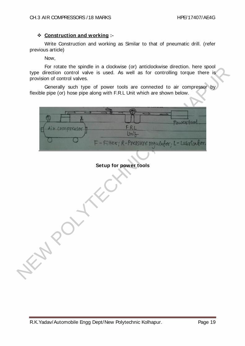
For rotate the spindle in a clockwise (or) anticlockwise direction. here spooltype direction control valve is used. As well as for controlling torque there isprovision of control valves.
Generally such type of power tools are connected to air compressor byflexible pipe (or) hose pipe along with F.R.L Unit which are shown below.
Setup for power tools

NEW P
OLYTECHNIC
, KOLH
APUR
CH.3 AIR COMPRESSORS /18 MARKS HPE/17407/AE4G
R.K.Yadav/Automobile Engg Dept/New Polytechnic Kolhapur. Page 20
Question Bank 3. Air compressor 18 Marks
1 Define term free air delivery (F.A.D.) 2 m.2 Define capacity of Compressor. 2 m.3 Define Isothermal efficiency of air Compressor. 2 m.45
6
State necessity of inter cooling in air compressor.Why reciprocating compressor is called as positive displacementcompressor.Briefly explain the different methods adopted for increasing isothermalefficiency of reciprocating air compressor.
2 m.
2 m.
2 m.
7 Define i) Volumetric efficiency, ii) Isothermal efficiency of an aircompressor, iii) Overall efficiency, iv) Capacity of compressor, v)Indicated Power
4 m.
8 Define air Compressor terminology. 4 m.i ) Free air delivery ii) Capacity of compressoriii) Piston displacement iv) Volumetric efficiency.v) Compressor efficiency vi) Mechanical efficiency
9
10
11
State various uses of compressed air
Write classification of air compressor (any 4 pts )
Classify compressor according to i) capacity of compressor ii) Airmotion
4 m.
4 m.
4 m.
12 Explain working of single stage reciprocating air compressor with helpof P-V diagram.
4 m.
13 Explain construction and working of two stage reciprocating aircompressor with help of P-V diagram. 4 m.
14 Explain with neat sketch working of axial flow compressor (rotary)Compare Centrifugal and Axial flow compressor 8 m.
15 Explain necessity of multi staging & inter cooling of compressor usingdiagram.
4 m.
16 Explain in brief factors affecting volumetric efficiency of reciprocatingair compressor.
4 m.
17 Compare merits & demerits of reciprocating compressor with rotarycompressor. 8 m.
18 Differentiate between Reciprocating and rotary air compressor. 8 m.19 Sketch and explain working of Screw compressor 4 m.20 Explain working principle of Centrifugal compressor with neat
sketch. State its merit over reciprocating compressor. 8 m.


![Shivaji University, Kolhapur. Electronics... · 1 Shivaji University, Kolhapur Shivaji University, Kolhapur. Syllabus / Structure [Revised from June-2009] (T.E. Electronics Engineering)](https://static.fdocuments.in/doc/165x107/5a7e734b7f8b9a2e6e8e7871/shivaji-university-electronics1-shivaji-university-kolhapur-shivaji-university.jpg)