
Integrable Optics Test Accelerator Sergei Nagaitsev Fermilab April 3, 2013.
Upload
aurora-yatesCategory
view
35download
0description

f
New Muon Lab SCRF Test Facility
Sergei NagaitsevOct 15, 2007

fILC S2 recommendation
• ILC S2 task force (string test definition) recommends: the minimum size system test needed to confirm the performance of a new design is a single RF unit with ILC like beam.– ILC RF unit is 3 CMs powered by a 10 MW MBK
• Many tests are statistical in nature, a longer string test with several RF units would be better.
Oct 15, 2007 2Nagaitsev

f
Oct 15, 2007 3Nagaitsev
Rough S2 Schedule
PhaseCompletion date Description
0 2005TTF/FLASH, not final cavity design, type 3 cryomodule, not full gradient, has beam
0.5 2008 Extra tests at TTF/FLASH with same type cryomodules as phase 0
1 20081 cryomodule, not final cavity design, type 3 cryomodule (and/or) STF type cryomodule, not full gradient, no beam
1.1 2009
1 RF unit, not all final cavity design, not all type 4 cryomodules, not full gradient, beam not needed for tests, but should be built so it and the LLRF are debugged for the next step
1.2 20101 RF unit (replacing cryomodules of phase 1.1), final cavity design, full gradient, type 4 cryomodules, with beam
1.3 20111 RF unit (replacing cryomodules of phase 1.1), final cavity design, full gradient, type DFM cryomodules, with beam
1.4 2011Tunnel mockup above ground. 1 RF unit perhaps built with parts taken from earlier tests. Includes RTML and e+ transport, no beam
2 2013N RF units at one site (of the final ILC?) as a system test of final designs from multiple manufacturers, no beam
3 2013 XFEL

f
Oct 15, 2007 4Nagaitsev
• 1st Cryomodule (2007)– Assemble a TESLA TTF type III CM from DESY “kit” – Cavities built and fully tested by DESY
• 2nd Cryomodule (2008)– Also TTF type III cryomodule– Cavities are processed and tested in the US– Electropolished and tested at JLAB, Cornell, and ANL/FNAL– Cryostat and cold mass from Zanon in Europe
• 3rd Cryomodule (2009)– 1st type IV ILC cryomodule built anywhere– Parts built in U.S. industry
• 4th-6th Cryomodules (2010-11)– Build ILC RF unit in U.S.– Transfer knowledge gained to Industry
Fermilab cryomodule plan

fNML
• NML is a facility to be located in the existing building at Fermilab (New Muon Lab)
• New Muon Lab building is part of Fermilab’s ILC Test Areas (ILCTA_NM)– Other areas are: MDB (horizontal SCRF cavity test stand),
IB1 (vertical test stand) etc.
• The first NML user will be the ILC program.– The cryomodule tests are also essential to Project X (β=1)– The Accelerator R&D (AARD) portion will first piggy-back
on these programs; its share will increase with time
Oct 15, 2007 5Nagaitsev
fFermilab NML plans
Oct 15, 2007 6Nagaitsev
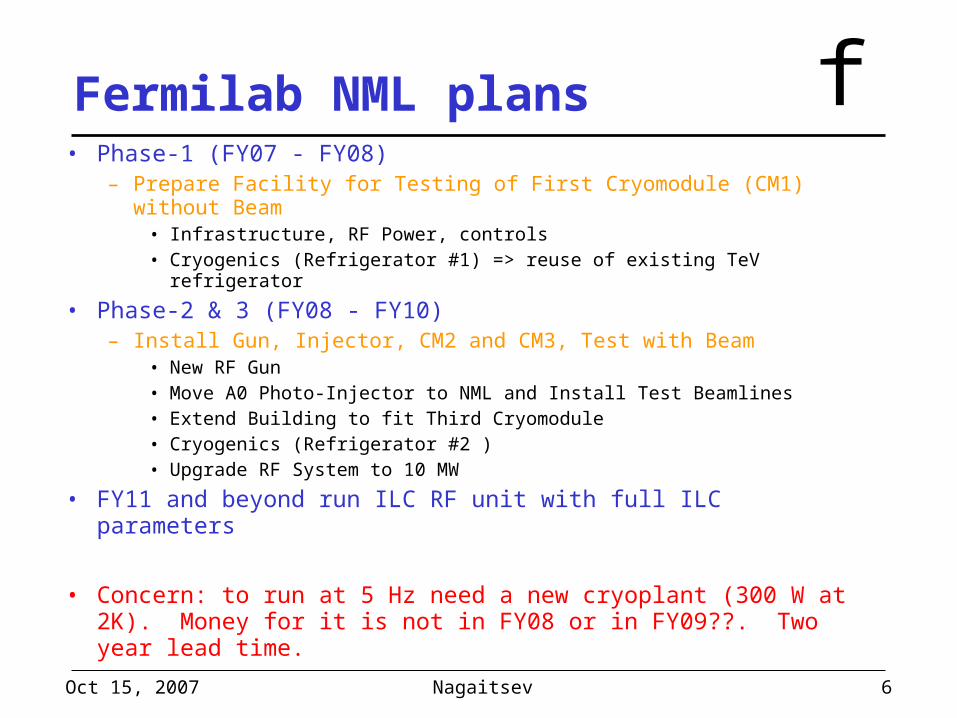
• Phase-1 (FY07 - FY08)– Prepare Facility for Testing of First Cryomodule (CM1) without
Beam• Infrastructure, RF Power, controls• Cryogenics (Refrigerator #1) => reuse of existing TeV
refrigerator
• Phase-2 & 3 (FY08 - FY10)– Install Gun, Injector, CM2 and CM3, Test with Beam
• New RF Gun• Move A0 Photo-Injector to NML and Install Test Beamlines• Extend Building to fit Third Cryomodule• Cryogenics (Refrigerator #2 )• Upgrade RF System to 10 MW
• FY11 and beyond run ILC RF unit with full ILC parameters
• Concern: to run at 5 Hz need a new cryoplant (300 W at 2K). Money for it is not in FY08 or in FY09??. Two year lead time.

fPhase-1 Layout of NML
Oct 15, 2007 7Nagaitsev
Cryomodule-1 (CM1) (Type III+)
Capture Cavity 2 (CC2)
CC2 RF System 5 MW RF System for CM1

fOverall layout of New Muon Lab
Oct 15, 2007 8Nagaitsev
CryomodulesCapture Cavity 1 (CC1)
CC2
Gun RF SystemCC1 & CC2 RF
RF Gun
5MW RF System for Cryomodules
Space for 10 MW RF System
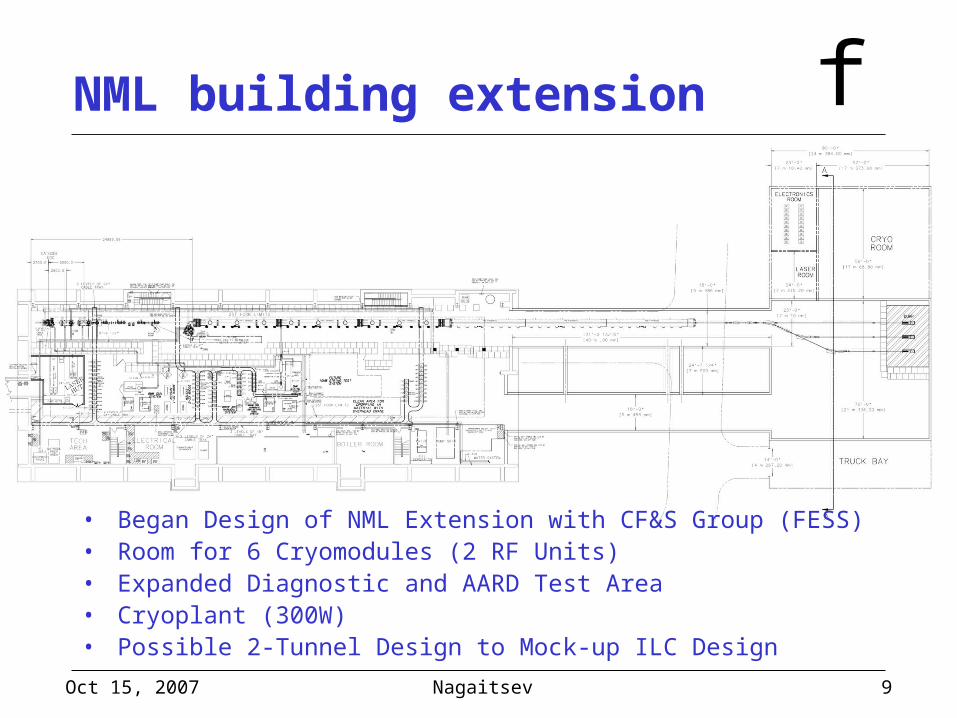
fNML building extension
• Began Design of NML Extension with CF&S Group (FESS)• Room for 6 Cryomodules (2 RF Units)• Expanded Diagnostic and AARD Test Area• Cryoplant (300W)• Possible 2-Tunnel Design to Mock-up ILC Design
Oct 15, 2007 9Nagaitsev

fCurrent photo of NML
Oct 15, 2007 10Nagaitsev

fNML summary• NML is being constructed to address the ILC S2 R&D list, to
test ILC baseline and alternative components, and to conduct AARD.– The A0 photoinjector will be part of the NML facility
• Progress is resource limited– FY07: 4.9M$ (M&S direct), 40 FTE’s– FY08: anticipate similar resources
• Collaborations:– SLAC will supply RF distribution system. May be a model for
Project X.– ANL, DESY, KEK, INFN
• Already have 2 graduate students in accelerator physics working on NML design.
• AARD program is still developing– Had a workshop in Nov 2006 to “gauge” outside interest
Oct 15, 2007 11Nagaitsev