New July12, 2019 EXHIBIT A · 2019. 7. 19. · july12, 2019 exhibit a scope of services for...
108
July12, 2019 EXHIBIT A SCOPE OF SERVICES FOR FINANCIAL PROJECT ID(S). 442765-1-32-01 DISTRICT One Highlands COUNTY
Transcript of New July12, 2019 EXHIBIT A · 2019. 7. 19. · july12, 2019 exhibit a scope of services for...

July12, 2019
EXHIBIT A
SCOPE OF SERVICES
FOR
FINANCIAL PROJECT ID(S). 442765-1-32-01
DISTRICT One
Highlands COUNTY
A-2
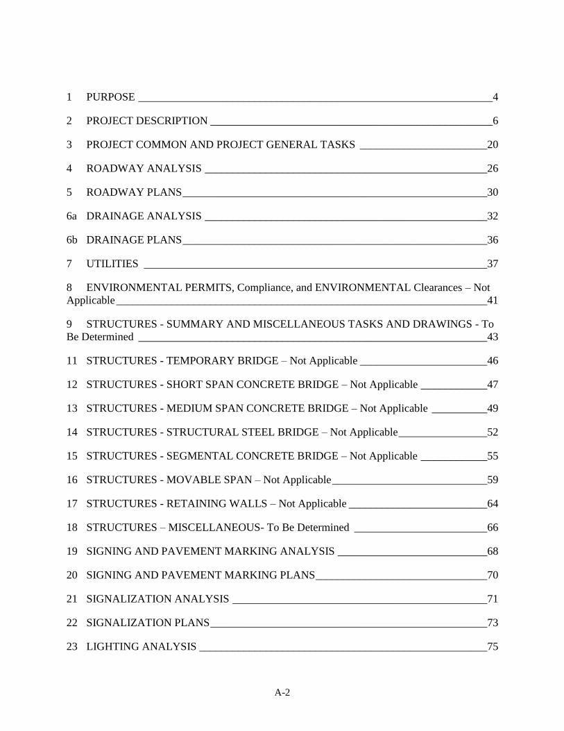
1 PURPOSE ________________________________________________________________4
2 PROJECT DESCRIPTION ___________________________________________________6
3 PROJECT COMMON AND PROJECT GENERAL TASKS _______________________20
4 ROADWAY ANALYSIS ___________________________________________________26
5 ROADWAY PLANS _______________________________________________________30
6a DRAINAGE ANALYSIS ___________________________________________________32
6b DRAINAGE PLANS _______________________________________________________36
7 UTILITIES ______________________________________________________________37
8 ENVIRONMENTAL PERMITS, Compliance, and ENVIRONMENTAL Clearances – Not
Applicable ___________________________________________________________________41
9 STRUCTURES - SUMMARY AND MISCELLANEOUS TASKS AND DRAWINGS - To
Be Determined _______________________________________________________________43
11 STRUCTURES - TEMPORARY BRIDGE – Not Applicable _______________________46
12 STRUCTURES - SHORT SPAN CONCRETE BRIDGE – Not Applicable ____________47
13 STRUCTURES - MEDIUM SPAN CONCRETE BRIDGE – Not Applicable __________49
14 STRUCTURES - STRUCTURAL STEEL BRIDGE – Not Applicable ________________52
15 STRUCTURES - SEGMENTAL CONCRETE BRIDGE – Not Applicable ____________55
16 STRUCTURES - MOVABLE SPAN – Not Applicable ____________________________59
17 STRUCTURES - RETAINING WALLS – Not Applicable _________________________64
18 STRUCTURES – MISCELLANEOUS- To Be Determined ________________________66
19 SIGNING AND PAVEMENT MARKING ANALYSIS ___________________________68
20 SIGNING AND PAVEMENT MARKING PLANS _______________________________70
21 SIGNALIZATION ANALYSIS ______________________________________________71
22 SIGNALIZATION PLANS __________________________________________________73
23 LIGHTING ANALYSIS ____________________________________________________75

A-3
24 LIGHTING PLANS ________________________________________________________77
25 LANDSCAPE ARCHITECTURE ANALYSIS __________________________________78
26 LANDSCAPE ARCHITECTURE PLANS ______________________________________80
27 SURVEY ________________________________________________________________81
28 PHOTOGRAMMETRY- To Be Determined ____________________________________86
29 MAPPING- Not Applicable _________________________________________________89
30 TERRESTRIAL MOBILE LiDAR- To Be Determined ____________________________91
31 ARCHITECTURE DEVELOPMENT- Not Applicable ____________________________94
32 NOISE BARRIERS IMPACT DESIGN ASSESSMENT IN THE DESIGN PHASE - Not
Applicable __________________________________________________________________101
33 INTELLIGENT TRANSPORTATION SYSTEMS ANALYSIS - Not Applicable ______102
34 INTELLIGENT TRANSPORTATION SYSTEMS PLANS - Not Applicable _________103
35 GEOTECHNICAL _______________________________________________________104
36 3D MODELING _________________________________________________________104
37 PROJECT REQUIREMENTS_______________________________________________106
38 INVOICING LIMITS _____________________________________________________108

1 PURPOSE
A-4
SCOPE OF SERVICES FOR CONSULTING ENGINEERING SERVICES
HIGHWAY AND BRIDGE/STRUCTURAL DESIGN
This Exhibit forms an integral part of the agreement between the State of Florida Department of
Transportation (hereinafter referred to as the DEPARTMENT or FDOT) and
___________________________ (hereinafter referred to as the CONSULTANT) relative to the
transportation facility described as follows:
Financial Project ID: 442765-1-32-01
Federal Aid Project No.: TBD
County Section No.: 09010
Description: SR 25/US27 from south of Tower Street (MP 18.735) to north of Tower
Street (MP 18.963), Highlands County
Bridge No(s).: N/A
Rail Road Crossing No: N/A
Context Classification: C2T
1 PURPOSE
The purpose of this Exhibit is to describe the scope of work and the responsibilities of the
CONSULTANT and the DEPARTMENT in connection with the design and preparation of a
complete set of construction contract documents and incidental engineering services, as
necessary, for improvements to the transportation facility described herein.
Major work mix includes: 0217 – Rigid Pavement Reconstruction
Major work groups include: 3.1: Minor Highway Design
Minor work groups include: 4.1: Miscellaneous Structures and Minor Bridge Design
6.1: Traffic Engineering Studies
7.1: Signing, Pavement Marking, and Channelization
7.2: Lighting
8.1: Control Surveying
8.2: Design, Right of Way, and Construction Surveying
8.3: Photogrammetric Mapping
15.0: Landscape Architect
Known alternative construction contracting methods include: N/A
The general objective is for the CONSULTANT to prepare a set of contract documents
including plans, specifications, supporting engineering analysis, calculations and other

STAGE II FPID(S): 442765-1-32-01
July 12, 2019
1 PURPOSE
A-5
technical documents in accordance with FDOT policy, procedures and requirements. These
Contract documents will be used by the contractor to build the project and test the project
components. These Contract documents will be used by the DEPARTMENT or its
Construction Engineering Inspection (CEI) representatives for inspection and final
acceptance of the project. The CONSULTANT shall follow a systems engineering process
to ensure that all required project components are included in the development of the
Contract documents and the project can be built as designed and to specifications.
The Scope of Services establishes which items of work in the FDOT Design Manual and
other pertinent manuals are specifically prescribed to accomplish the work included in this
contract, and also indicate which items of work will be the responsibility of the
CONSULTANT and/or the DEPARTMENT.
The CONSULTANT shall be aware that as a project is developed, certain modifications
and/or improvements to the original concepts may be required. The CONSULTANT shall
incorporate these refinements into the design and consider such refinements to be an
anticipated and integral part of the work. This shall not be a basis for any supplemental fee
request(s).
The CONSULTANT shall demonstrate good project management practices while working
on this project. These include communication with the DEPARTMENT and others as
necessary, management of time and resources, and documentation. The CONSULTANT
shall set up and maintain throughout the design of the project a contract file in accordance
with DEPARTMENT procedures. CONSULTANTs are expected to know the laws and rules
governing their professions and are expected to provide services in accordance with current
regulations, codes and ordinances and recognized standards applicable to such professional
services. The Consultant shall provide qualified technical and professional personnel to
perform to Department standards and procedures, the duties and responsibilities assigned
under the terms of this agreement. The Consultant shall minimize to the maximum extent
possible the Department’s need to apply its own resources to assignments authorized by the
Department.
The DEPARTMENT will provide contract administration, management services, and
technical reviews of all work associated with the development and preparation of contract
documents, including Construction documents. The Department’s technical reviews are for
high-level conformance and are not meant to be comprehensive reviews. The
CONSULTANT shall be fully responsible for all work performed and work products
developed under this Scope of Services. The DEPARTMENT may provide job-specific
information and/or functions as outlined in this contract, if favorable.

STAGE II FPID(S): 442765-1-32-01
July 12, 2019
2 PROJECT DESCRIPTION
A-6
2 PROJECT DESCRIPTION
The CONSULTANT shall investigate the status of the project and become familiar with
concepts and commitments (typical sections, alignments, etc.) developed from prior studies
and/or activities. If a Preliminary Engineering Report is available from a prior or current
Project Development and Environmental (PD&E) study, the CONSULTANT shall use the
approved concepts as a basis for the design unless otherwise directed by the
DEPARTMENT.
RRR project on US 27 from S of Tower Street to North of Tower Street utilizing
rigid pavement for rehabilitation. The northbound limits begin at MP 18.735 and
end at MP 18.880. The southbound project limits begin at MP 18.840 and end at
MP 18.963. The limits of the reconstruction include all travel lanes, auxiliary
lanes and paved shoulders. Milling and resurfacing will be necessary on the side
streets. Within the project limits, new sidewalk will be constructed.
2.1 Project General and Roadway (Activities 3, 4, and 5)
Public Involvement: N/A
Other Agency Presentations/Meetings: N/A
Joint Project Agreements: N/A
Specification Package Preparation: One
Value Engineering: N/A
Risk Assessment Workshop: N/A
Plan Type: Plan only
Typical Section: TBD
Pavement Design: Two
Pavement Type Selection Report(s): Submitted with phase reviews
Cross Slope: TBD
Access Management Classification: 05
Transit Route Features: N/A
Major Intersections/Interchanges: US 27 and Tower Street
Roadway Alternative Analysis: N/A
Level of TCP Plans: TBD

STAGE II FPID(S): 442765-1-32-01
July 12, 2019
2 PROJECT DESCRIPTION
A-7
Temporary Lighting: N/A
Temporary Signals: N/A
Temporary Drainage: N/A
Design Variations/Exceptions: TBD
Back of Sidewalk Profiles: N/A
Selective Clearing and Grubbing: N/A
2.2 Drainage (Activities 6a and 6b)
System Type: The existing system is open with ditch conveyance on US 27 and closed system with curb and gutter on Dal Hall Blvd.
Stormwater Management Facility Sites Studies: N/A
Cross Drains: N/A
2.3 Utilities Coordination (Activity 7)
The CONSULTANT is responsible to certify that all necessary arrangements for utility work on this project have been made and will not conflict with the physical construction schedule. The CONSULTANT should coordinate with DEPARTMENT personnel to coordinate transmittals to Utility Companies and meet production schedules.
The CONSULTANT shall ensure FDOT standards, policies, procedures, practices, and design criteria are followed concerning utility coordination.
The CONSULTANT may employ more than one individual or utility engineering consultant to provide utility coordination and engineering design expertise. The CONSULTANT shall identify a dedicated person responsible for managing all utility coordination activities. This person shall be contractually referred to as the Utility Coordination Manager and shall be identified in the CONSULTANT proposal. The Utility Coordination Manager shall be required to satisfactorily demonstrate to the FDOT District Utilities Administrator that they have the following knowledge, skills, and expertise:
A minimum of 4 years of experience performing utility coordination in accordance with FDOT, Federal Highway Administration (FHWA), and American Association of State Highway and Transportation Officials (AASHTO) standards, policies, and procedures.
A thorough knowledge of the FDOT plans production process and District utility coordination process.
A thorough knowledge of FDOT agreements, standards, policies, and procedures.
The Utility Coordination Manager shall be responsible for managing all utility coordination, including the following:
Assuring that Utility Coordination and accommodation is in accordance to the FDOT,

STAGE II FPID(S): 442765-1-32-01
July 12, 2019
2 PROJECT DESCRIPTION
A-8
FHWA, and AASHTO standards, policies, procedures, and design criteria.
Assisting the engineer of record in identifying all existing utilities and coordinating any new installations. Assisting the Engineer of Record with resolving utility conflicts.
Scheduling and performing utility coordination meetings, keeping and distribution of minutes/action items of all utility meetings, and ensuring expedient follow-up on all unresolved issues.
Distributing all plans, conflict matrixes and changes to affected utility owners and making sure this information is properly coordinated and documented.
Identifying and coordinating the completion of any FDOT or utility owner agreement that is required for reimbursement, or accommodation of the utility facilities associated with the project.
Review and certify to the District Utilities Administrator that all Utility Work Schedules are correct and in accordance with the Department’s standards, policies, and procedures.
Prepare, review and process all utility related reimbursable paperwork inclusive of betterment and salvage determination.
The CONSULTANT’s utility coordination work shall be performed and directed by the Utility Coordination Manager that was identified and approved by FDOT’s Project Manager. Any proposed change of the approved Utility Coordination Manager shall be subject to review and approval by FDOT’s Project Manager prior to any change being made in this contract.
Town of Lake Placid Duke Energy
Century Link (Level 3) Century Link
2.4 Environmental Permits, Compliances, and Environmental Clearances
(Activity 8) - Not Applicable
Permits are not anticipated

STAGE II FPID(S): 442765-1-32-01
July 12, 2019
2 PROJECT DESCRIPTION
A-9
2.5 Structures (Activities 9 – 18) - To Be Determined
Bridge(s): N/A
Type of Bridge Structure Work:
▪ BDR- N/A
▪ Temporary Bridge - N/A
▪ Short Span Concrete - N/A
▪ Medium Span Concrete - N/A
▪ Structural Steel - N/A
▪ Segmental Concrete - N/A
▪ Movable Span - N/A
Retaining Walls: N/A
Noise Barrier Walls: N/A
Miscellaneous: TBD
2.6 Signing and Pavement Markings (Activities 19 & 20)
The CONSULTANT shall prepare signing and pavement marking plans in accordance with Department criteria.
Design should reflect FDOT - District One Signing & Pavement Marking Policies and Procedures as indicated in the latest Signing and Marking Updates folder located at website address https://ftp.fdot.gov/file/d/FTP/FDOT/d1/traffops/Signing%20and%20Marking/.
2.7 Signalization (Activities 21 & 22)
Intersections: [List all existing and proposed signalized intersections and requirements, (i.e., loop replacement, mast arms, etc.) or N/A].
Traffic Data Collection: [List all locations that will require data collection. Describe data to be collected at each location or N/A].
Traffic Studies: [List all studies required and locations or N/A].
Count Stations: [List number of count stations or N/A].
Traffic Monitoring Sites: [List number of Traffic Monitoring Sites on or within one-half mile of project or N/A].
2.8 Lighting (Activities 23 & 24)
[Provide limits and proposed type of lighting. Describe lighting reports required or N/A].
STAGE II FPID(S): 442765-1-32-01
July 12, 2019
2 PROJECT DESCRIPTION
A-10
2.9 Landscape Architecture (Activities 25 & 26)
Include coordination with existing and/or proposed underground utilities including but not limited to FDOT lighting, drainage and ITS. Landscape coordination with ITS shall include both underground conflicts and above-ground impacts to existing and/or proposed ITS coverage. The CONSULTANT shall closely coordinate with the Department’s ITS units to ensure that all conflicts are identified, addressed and mitigated in the Contract Documents.
Planting Plans: Provide planting plans as necessary in accordance with FDM Section 229 Selective Clearing and Grubbing.
Irrigation Plans: Provide irrigation plans as necessary to ensure that once roadway construction is completed – the irrigation system (currently existing within the medians) is fully operational and that the local agency (City of Lake Placid) can continue operation of the existing irrigation system. Irrigation plans are to identify any existing irrigation component as necessary to make any adjustments to the system for continued 100% operation of the irrigation system.
Hardscape Plans: N/A
Outdoor Advertising: Indicate if view zones of legally permitted outdoor advertising signs are within the project limits. List the number of sign structures, the number of sign faces (single, double, triple faced), and the number of existing permitted signs. Landscape Architect is to contact each permitted sign owner. Landscape Architect is to distribute project plans as necessary to coordinate with the permitted sign owner.
2.10 Survey (Activity 27)
Design Survey: As directed
Subsurface Utility Exploration: Subsurface Utility Exploration: SUE all locations that include new underground infrastructure or earthwork excavation (i.e., drilled shafts, bridge piles, strain poles, mast arms, miscellaneous foundations, drainage structures, pipe culverts, new ditches, etc.) in areas that work will be performed. (SUE locations will be negotiated by the DUA or their Designee) (See D1 SUE Policy Direction)
Right of Way Survey: N/A
Vegetation Survey: N/A
2.11 Photogrammetry (Activity 28)
To be determined
2.12 Mapping (Activity 29)
Control Survey Map: As directed

STAGE II FPID(S): 442765-1-32-01
July 12, 2019
2 PROJECT DESCRIPTION
A-11
Right of Way Map: N/A
Legal Descriptions: To be determined
Maintenance Map: To be determined
Miscellaneous Items: To be determined
2.13 Terrestrial Mobile LiDAR (Activity 30)
To be determined
2.14 Architecture (Activity 31) - Not Applicable
2.15 Noise Barriers (Activity 32) - Not Applicable
2.16 Intelligent Transportation Systems (Activities 33 & 34) - Not Applicable
2.17 Geotechnical (Activity 35)
The DEPARTMENT will provide all necessary Geotechnical services for this
project. The CONSULTANT shall request from the DEPARTMENT all
Geotechnical data and recommendations necessary for this project by such time as
will support the DEPARTMENT’s original project schedule or any subsequent
DEPARTMENT-approved revisions thereto.
2.18 3D Modeling (Activity 36)
The CONSULTANT shall be responsible for all 3D Modeling services for this
project.
2.19 Project Schedule
Within ten (10) days after the Notice-To-Proceed, and prior to the CONSULTANT beginning work, the CONSULTANT shall provide a detailed project activity/event schedule for DEPARTMENT and CONSULTANT scheduled activities required to meet the current DEPARTMENT Production Date. The schedule shall be based upon the
DEPARTMENT’S current project schedule. The current production date is May 2023. The schedule shall be accompanied by an anticipated payout and fiscal progress curve. For
the purpose of scheduling, the CONSULTANT shall allow for a four week review time for each phase submittal and any other submittals as appropriate.
The schedule shall indicate all required submittals.
All fees and price proposals are to be based on the negotiated schedule of 60 months for
final construction contract documents. However, the contract deadline is 60 months from the Notice to Proceed.
Periodically, throughout the life of the contract, the project schedule and payout and fiscal progress curves shall be reviewed and, with the approval of the DEPARTMENT, adjusted as

STAGE II FPID(S): 442765-1-32-01
July 12, 2019
2 PROJECT DESCRIPTION
A-12
necessary to incorporate changes in the Scope of Services and progress to date.
The approved schedule and schedule status report, along with progress and payout curves, shall be submitted with the monthly progress report.
The schedule shall be submitted in an FDOT system-compatible format.
2.20 Submittals
The CONSULTANT shall furnish construction contract documents as required by the DEPARTMENT to adequately control, coordinate, and approve the work concepts. The CONSULTANT shall distribute submittals as directed by the DEPARTMENT. The DEPARTMENT will determine the specific number of copies required prior to each submittal.
2.21 Provisions for Work
All work shall be prepared with English units in accordance with the latest editions of standards and requirements utilized by the DEPARTMENT which include, but are not limited to, publications such as:
▪ General
o Title 29, Part 1910, Standard 1910.1001, Code of Federal Regulations (29
C.F.R. 1910.1001) – Asbestos Standard for Industry, U.S. Occupational
Safety and Health Administration (OSHA)
o 29 C.F.R. 1926.1101 – Asbestos Standard for Construction, OSHA
o 40 C.F.R. 61, Subpart M - National Emission Standard for Hazardous Air
Pollutants (NESHAP), Environmental Protection Agency (EPA)
o 40 C.F.R. 763, Subpart E – Asbestos-Containing Materials in Schools, EPA
o 40 C.F.R. 763, Subpart G – Asbestos Worker Protection, EPA
o Americans with Disabilities Act (ADA) Standards for Accessible Design
o AASHTO – A Policy on Design Standards Interstate System
o AASHTO – Roadside Design Guide
o AASHTO – Roadway Lighting Design Guide
o AASHTO – A Policy for Geometric Design of Highways and Streets
o AASHTO – Highway Safety Manual
o Rule Chapter 5J-17, Florida Administrative Code (F.A.C.), Standards of
Practice for Professional Surveyors and Mappers
o Chapter 469, Florida Statutes (F.S.) – Asbestos Abatement
o Rule Chapter 62-257, F.A.C., Asbestos Program
o Rule Chapter 62-302, F.A.C., Surface Water Quality Standards
o Code of Federal Regulations (C.F.R.)
o Florida Administrative Codes (F.A.C.)
o Chapters 20, 120, 215, 455, Florida Statutes (F.S.) – Florida Department of
Business & Professional Regulations Rules
o Florida Department of Environmental Protection Rules
o FDOT Basis of Estimates Manual
o FDOT Computer Aided Design and Drafting (CADD) Manual

STAGE II FPID(S): 442765-1-32-01
July 12, 2019
2 PROJECT DESCRIPTION
A-13
o FDOT Standard Plans
o FDOT Flexible Pavement Design Manual
o FDOT - Florida Roundabout Guide
o FDOT Handbook for Preparation of Specifications Package
o FDOT Standard Plans Instructions
o FDOT Manual of Uniform Minimum Standards for Design, Construction
and Maintenance for Streets and Highways (“Florida Greenbook”)
o FDOT Materials Manual
o FDOT Pavement Type Selection Manual
o FDOT Design Manual
o FDOT Procedures and Policies
o FDOT Procurement Procedure 001-375-030, Compensation for Consultant
Travel Time on Professional Services Agreements
o FDOT Project Development and Environmental Manual
o FDOT Project Traffic Forecasting Handbook
o FDOT Public Involvement Handbook
o FDOT Rigid Pavement Design Manual
o FDOT Standard Specifications for Road and Bridge Construction
o FDOT Utility Accommodation Manual
o Manual on Speed Zoning for Highways, Roads, and Streets in Florida
o Federal Highway Administration (FHWA) - Manual on Uniform Traffic
Control Devices (MUTCD)
o FHWA – National Cooperative Highway Research Program (NCHRP)
Report 672, Roundabouts: An Informational Guide
o FHWA Roadway Construction Noise Model (RCNM) and Guideline
Handbook
o Florida Fish and Wildlife Conservation Commission - Standard Manatee
Construction Conditions 2005
o Florida Statutes (F.S.)
o Florida’s Level of Service Standards and Guidelines Manual for Planning
o Model Guide Specifications – Asbestos Abatement and Management in
Buildings, National Institute for Building Sciences (NIBS)
o Quality Assurance Guidelines
o Safety Standards
o Any special instructions from the DEPARTMENT
▪ Roadway
o FDOT – Florida Intersection Design Guide
o FDOT - Project Traffic Forecasting Handbook
o FDOT - Quality/Level of Service Handbook
o Florida’s Level of Service Standards and Highway Capacity Analysis for
the SHS
o Transportation Research Board (TRB) - Highway Capacity Manual
▪ Permits
o Chapter 373, F.S. – Water Resources
o US Fish and Wildlife Service Endangered Species Programs

STAGE II FPID(S): 442765-1-32-01
July 12, 2019
2 PROJECT DESCRIPTION
A-14
o Florida Fish and Wildlife Conservation Commission Protected Wildlife
Permits
o Bridge Permit Application Guide, COMDTPUB P16591.3C
o Building Permit
▪ Drainage
o FDOT Bridge Hydraulics Handbook
o FDOT Culvert Handbook
o FDOT Drainage Manual
o FDOT Erosion and Sediment Control Manual
o FDOT Exfiltration Handbook
o FDOT Hydrology Handbook
o FDOT Open Channel Handbook
o FDOT Optional Pipe Materials Handbook
o FDOT Storm Drain Handbook
o FDOT Stormwater Management Facility Handbook
o FDOT Temporary Drainage Handbook
o FDOT Drainage Connection Permit Handbook
o FDOT Bridge Scour Manual
▪ Survey and Mapping
o All applicable Florida Statutes and Administrative Codes
o Applicable Rules, Guidelines Codes and authorities of other Municipal,
County, State and Federal Agencies.
o FDOT Aerial Surveying Standards for Transportation Projects Topic 550-
020-002
o FDOT Right of Way Mapping Handbook
o FDOT Surveying Procedure Topic 550-030-101
o Florida Department of Transportation Right of Way Procedures Manual
o Florida Department of Transportation Surveying Handbook
o Right of Way Mapping Procedure 550-030-015
▪ Traffic Engineering and Operations and ITS
o AASHTO - An Information Guide for Highway Lighting
o AASHTO - Guide for Development of Bicycle Facilities
o FHWA Standard Highway Signs Manual
o FDOT Manual on Uniform Traffic Studies (MUTS)
o FDOT Median Handbook
o FDOT Traffic Engineering Manual
o National Electric Safety Code
o National Electrical Code
▪ Florida’s Turnpike Enterprise
o Florida’s Turnpike Plans Preparation and Practices Handbook (TPPPH)
o Florida’s Turnpike Lane Closure Policy
o Florida’s Turnpike Drainage Manual Supplement
o Rigid Pavement Design Guide for Toll Locations with Electronic Toll

STAGE II FPID(S): 442765-1-32-01
July 12, 2019
2 PROJECT DESCRIPTION
A-15
Collection
o Flexible Pavement Design Guide for Toll Locations with Electronic Toll
Collection
o Florida’s Turnpike General Tolling Requirements (GTR)
o Additional Florida’s Turnpike Enterprise standards, guides, and policies for
design and construction can be found on the FTE Design Website:
http://design.floridasturnpike.com
▪ Traffic Monitoring
o American Institute of Steel Construction (AISC) Manual of Steel
Construction, referred to as “AISC Specifications”
o American National Standards Institute (ANSI) RP-8-00 Recommended
Practice for Roadway Lighting
o AASHTO AWS D1.1/ANSI Structural Welding Code – Steel
o AASHTO D1.5/AWS D1.5 Bridge Welding Code
o FHWA Traffic Detector Handbook
o FDOT General Interest Roadway Data Procedure
o FHWA Traffic Monitoring Guide
o FDOT’s Traffic/Polling Equipment Procedures
▪ Structures
o AASHTO Load and Resistance Factor Design (LRFD) Bridge Design
Specifications and Interims
o AASHTO LRFD Movable Highway Bridge Design Specifications and
Interims
o AASHTO Standard Specifications for Structural Supports for Highway
Signs, Luminaires and Traffic Signals, and Interims.
o AASHTO/-AWS-D1. 5M/D1.5: An American National Standard Bridge
Welding Code
o AASHTO Guide Specifications for Structural Design of Sound Barriers
o AASHTO Manual for Condition Evaluation and Load and Resistance
Factor Rating (LRFR) of Highway Bridges
o FDOT Bridge Load Rating Manual
o FDOT Structures Manual
o FDOT Structures Design Bulletins (available on FDOT Structures web site
only)
o
▪ Geotechnical
o FHWA Checklist and Guidelines for Review of Geotechnical Reports and
Preliminary Specifications
o Manual of Florida Sampling and Testing Methods
o Soils and Foundation Handbook
▪ Landscape Architecture
o Florida Department of Agriculture and Consumer Services Grades and
Standards for Nursery Plants

STAGE II FPID(S): 442765-1-32-01
July 12, 2019
2 PROJECT DESCRIPTION
A-16
▪ Architectural
o Building Codes
o Florida Building Code:
• Building
• Fuel Gas
• Mechanical
• Plumbing
• Existing Building
o Florida Accessibility Code for Building Construction
o Rule Chapter 60D, F.A.C., Division of Building Construction
o Chapter 553, F.S. – Building Construction Standards
o ANSI A117.1 2003 Accessible and Usable Building and Facilities
o Titles II and III, Americans With Disabilities Act (ADA), Public Law 101-
336; and the ADA Accessibility Guidelines (ADAAG)
▪ Architectural – Fire Codes and Rules
o National Fire Protection Association (NFPA) - Life Safety Code
o NFPA 70 - National Electrical Code
o NFPA 101 - Life Safety Code
o NFPA 10 - Standard for Portable Fire Extinguishers
o NFPA 11 - Standard for Low-Expansion Foam Systems
o NFPA 11A - Standard for High- and Medium-Expansion Foam Systems
o NFPA 12 - Standard for Carbon Dioxide Extinguishing Systems
o NFPA 13 - Installation of Sprinkler Systems
o NFPA 30 - Flammable and Combustible Liquids Code
o NFPA 54 - National Gas Fuel Code
o NFPA 58 - LP-Gas Code
o Florida Fire Prevention Code as adopted by the State Fire Marshal –
Consult with the Florida State Fire Marshal’s office for other frequently
used codes.
▪ Architectural – Extinguishing Systems
o NFPA 10 - Fire Extinguishers
o NFPA 13 - Sprinkler
o NFPA 14 - Standpipe and Hose System
o NFPA 17 - Dry Chemical
o NFPA 20 - Centrifugal Fire Pump
o NFPA 24 - Private Fire Service Mains
o NFPA 200 - Standard on Clean Agent Fire Extinguishing Systems
▪ Architectural – Detection and Fire Alarm Systems
o NFPA 70 - Electrical Code
o NFPA 72 - Standard for the Installation, Maintenance and Use of Local
Protective Signaling Systems
o NFPA 72E - Automatic Fire Detectors
STAGE II FPID(S): 442765-1-32-01
July 12, 2019
2 PROJECT DESCRIPTION
A-17
o NFPA 72G - Installation, Maintenance, and Use of Notification Appliances
o NFPA 72H -Testing Procedures for Remote Station and Proprietary
Systems
o NFPA 74 - Household Fire Warning Equipment
o NFPA 75 - Protection of Electronic Computer Equipment
▪ Architectural – Mechanical Systems
o NFPA 90A - Air Conditioning and Ventilating Systems
o NFPA 92A - Smoke Control Systems
o NFPA 96 - Removal of Smoke and Grease-Laden Vapors from Commercial
Cooking Equipment
o NFPA 204M - Smoke and Heating Venting
▪ Architectural – Miscellaneous Systems
o NFPA 45 - Laboratories Using Chemicals
o NFPA 80 - Fire Doors and Windows
o NFPA 88A - Parking Structures
o NFPA 105- Smoke and Draft-control Door Assemblies
o NFPA 110 - Emergency and Standby Power Systems
o NFPA 220 - Types of Building Construction
o NFPA 241 - Safeguard Construction, Alteration, and Operations
o Rule Chapter 69A-47, F.A.C., Uniform Fire Safety For Elevators
o Rule Chapter 69A-51, F.A.C., Boiler Safety
▪ Architectural – Energy Conservation
o Rule Chapter 60D-4, F.A.C., Rules For Construction and Leasing of State
Buildings To Insure Energy Conservation
o Section 255.255, F.S., Life-Cycle Costs
▪ Architectural – Elevators
o Rule Chapter 61C-5, F.A.C., Florida Elevator Safety Code
o ASME A-17.1, Safety Code for Elevators and Escalators
o Architectural – Floodplain Management Criteria
o Section 255.25, F.S., Approval Required Prior to Construction or Lease of
Buildings
o Rules of the Federal Emergency Management Agency (FEMA)
▪ Architectural – Other
o Rule Chapter 64E-6, F.A.C., Standards for On Site Sewage Disposal
Systems (Septic Tanks)
o Rule Chapter 62-600, F.A.C., Domestic Wastewater Facilities
o Rule Chapter 62-761, F.A.C., Underground Storage Tank Systems
o American Concrete Institute
o American Institute of Architects - Architect’s Handbook of Professional
Practice
o American Society for Testing and Materials - ASTM Standards
o Brick Institute of America

STAGE II FPID(S): 442765-1-32-01
July 12, 2019
2 PROJECT DESCRIPTION
A-18
o DMS - Standards for Design of State Facilities
o Florida Concrete Products Association
o FDOT – ADA/Accessibility Procedure
o FDOT – Building Code Compliance Procedure
o FDOT – Design Build Procurement and Administration
o LEED (Leadership in Energy and Environmental Design) Green Building
Rating System
o National Concrete Masonry Association
o National Electrical Code
o Portland Cement Association - Concrete Masonry Handbook
o United State Green Building Council (USGBC)
2.22 Services to be Performed by the DEPARTMENT When appropriate and /or
available, the DEPARTMENT will provide project data including:
▪ Numbers for field books.
▪ Preliminary Horizontal Network Control.
▪ Access for the CONSULTANT to utilize the DEPARTMENT’s Information
Technology Resources.
▪ All Department agreements with Utility Agency Owner (UAO).
▪ All certifications necessary for project letting.
▪ Building Construction Permit Coordination (Turnpike)
▪ All information that may come to the DEPARTMENT pertaining to future
improvements.
▪ All future information that may come to the DEPARTMENT during the term of
the CONSULTANT’s Agreement, which in the opinion of the DEPARTMENT
is necessary for the prosecution of the work.
▪ Available traffic and planning data.
▪ All approved utility relocations.
▪ Project utility certification to the DEPARTMENT’s Central Office.
▪ Any necessary title searches.
▪ Engineering standards review services.
▪ All available information in the possession of the DEPARTMENT pertaining to
utility companies whose facilities may be affected by the proposed construction.
▪ All future information that may come to the DEPARTMENT pertaining to
subdivision plans so that the CONSULTANT may take advantage of additional
areas that can be utilized as part of the existing right of way.
▪ Systems traffic for Projected Design Year, with K, D, and T factors.
▪ Previously constructed Highway Beautification or Landscape Construction
Plans
▪ Landscape Opportunity Plan(s)
▪ Existing right of way maps.
▪ Existing cross slope data for all RRR projects.
▪ Existing pavement evaluation report for all RRR projects.
▪ PD&E Documents
▪ Design Reports
▪ Letters of authorization designating the CONSULTANT as an agent of the
DEPARTMENT in accordance with F.S. 337.274.

STAGE II FPID(S): 442765-1-32-01
July 12, 2019
2 PROJECT DESCRIPTION
A-19
▪ Phase reviews of plans and engineering documents.
▪ Regarding Environmental Permitting Services:
o Approved Permit Document when available.
o Approval of all contacts with environmental agencies.
o General philosophies and guidelines of the DEPARTMENT to be used in
the fulfillment of this contract. Objectives, constraints, budgetary
limitations, and time constraints will be completely defined by the Project
Manager.
o Appropriate signatures on application forms.

STAGE II FPID(S): 442765-1-32-01
July 12, 2019
3 PROJECT COMMON AND PROJECT GENERAL TASKS
A-20
3 PROJECT COMMON AND PROJECT GENERAL TASKS
Project Common Tasks
Project Common Tasks, as listed below, are work efforts that are applicable to many project
activities, 4 (Roadway Analysis) through 36 (3D Modeling). These tasks are to be included
in the project scope in each applicable activity when the described work is to be performed
by the CONSULTANT.
Cost Estimates: The CONSULTANT is responsible for producing a construction cost
estimate and reviewing and updating the cost estimate when scope changes occur and/or at
milestones of the project. Prior to 60% plans or completion of quantities, the
DEPARTMENT’s Long Range Estimate (L.R.E.) system will be used to produce a
conceptual estimate, according to District policy. Once the quantities have been developed
(beginning at 60% plans and no later than 90% plans) the CONSULTANT shall be
responsible for inputting the pay items and quantities into AASHTOWare Project
Preconstruction through the use of the DEPARTMENT’s Designer Interface for generating
the summary of quantities and the FDOT’s in-house estimates. A Summary of Pay Items
sheet shall be prepared with all required Plans submittals as required.
Technical Special Provisions: The CONSULTANT shall provide Technical Special
Provisions for all items of work not covered by the Standard Specifications for Road and
Bridge Construction and the workbook of implemented modifications.
A Technical Special Provision shall not modify the Standard Specifications and
implemented modifications in any way.
The Technical Special Provisions shall provide a description of work, materials, equipment
and specific requirements, method of measurement and basis of payment. Proposed
Technical Special Provisions will be submitted to the District Specifications Office for
initial review at the time of the Phase III plans review submission to the DEPARTMENT’s
Project Manager. This timing will allow for adequate processing time prior to final
submittal. The Technical Special Provisions will be reviewed for suitability in accordance
with the Handbook for Preparation of Specification Packages. The District Specifications
Office will forward the Technical Special Provisions to the District Legal Office for their
review and comment. All comments will be returned to the CONSULTANT for correction
and resolution. Final Technical Special Provisions shall be digitally signed and sealed in
accordance with applicable Florida Statutes.
The CONSULTANT shall contact the appropriate District Specifications Office for details
of the current format to be used before starting preparations of Technical Special Provisions.
Modified Special Provisions: The CONSULTANT shall provide Modified Special
Provisions as required by the project. Modified Special Provisions are defined in the
Specifications Handbook.

STAGE II FPID(S): 442765-1-32-01
July 12, 2019
3 PROJECT COMMON AND PROJECT GENERAL TASKS
A-21
A Modified Special Provision shall not modify the first nine sections of the Standard
Specifications and implemented modifications in any way. All modifications to other
sections must be justified to the appropriate District and Central Specifications Offices to be
included in the project's specifications package.
Field Reviews: The CONSULTANT shall make as many trips to the project site as required
to obtain necessary data for all elements of the project.
Technical Meetings: The CONSULTANT shall attend all technical meetings necessary to
execute the Scope of Services of this contract. This includes meetings with DEPARTMENT
and/or Agency staff, between disciplines and subconsultants, such as access management
meetings, pavement design meetings, local governments, railroads, airports, progress review
meetings (phase review), and miscellaneous meetings. The CONSULTANT shall prepare,
and submit to the DEPARTMENT’s Project Manager for review, the meeting minutes for all
meetings attended by them. The meeting minutes are due within five (5) working days of
attending the meeting.
Quality Assurance/Quality Control: It is the intention of the DEPARTMENT that design
CONSULTANTS, including their subconsultant(s), are held responsible for their work,
including plans review. The purpose of CONSULTANT plan reviews is to ensure that
CONSULTANT plans follow the plan preparation procedures outlined in the FDOT Design
Manual, that state and federal design criteria are followed with the DEPARTMENT concept,
and that the CONSULTANT submittals are complete. All subconsultant document
submittals shall be submitted by the subconsultant directly to the CONSULTANT for their
independent Quality Assurance/Quality Control review and subsequent submittal to the
DEPARTMENT.
It is the CONSULTANT'S responsibility to independently and continually QC their plans
and other deliverables. The CONSULTANT should regularly communicate with the
DEPARTMENT's Design Project Manager to discuss and resolve issues or solicit opinions
from those within designated areas of expertise.
The CONSULTANT shall be responsible for the professional quality, technical accuracy
and coordination of all surveys, designs, drawings, specifications and other services
furnished by the CONSULTANT and their subconsultant(s) under this contract.
The CONSULTANT shall provide a Quality Control Plan that describes the procedures to
be utilized to verify, independently check, and review all maps, design drawings,
specifications, and other documentation prepared as a part of the contract. The
CONSULTANT shall describe how the checking and review processes are to be
documented to verify that the required procedures were followed. The Quality Control Plan
shall be one specifically designed for this project. The CONSULTANT shall submit a
Quality Control Plan for approval within twenty (20) business days of the written Notice to
Proceed and it shall be signed by the CONSULTANT’s Project Manager and the
CONSULTANT QC Manager. The Quality Control Plan shall include the names of the
CONSULTANT’s staff that will perform the quality control reviews. The Quality Control
reviewer shall be a Florida Licensed Professional Engineer fully prequalified under F.A.C.
STAGE II FPID(S): 442765-1-32-01
July 12, 2019
3 PROJECT COMMON AND PROJECT GENERAL TASKS
A-22
14-75 in the work type being reviewed. A marked up set of prints from a Quality Control
Review indicating the reviewers for each component (structures, roadway, drainage, signals,
geotechnical, signing and marking, lighting, landscape, surveys, etc.) and a written
resolution of comments on a point-by-point basis will be required, if requested by the
DEPARTMENT, with each phase submittal. The responsible Professional Engineer,
Landscape Architect, or Professional Surveyor & Mapper that performed the Quality
Control review will sign a statement certifying that the review was conducted and found to
meet required specifications.
The CONSULTANT shall, without additional compensation, correct all errors or
deficiencies in the designs, maps, drawings, specifications and/or other products and
services.
Independent Peer Review: When directed by the DEPARTMENT, a subconsultant may
perform Independent Peer Reviews.
Independent Peer Review and a Constructability/Bidability Review for design Phase Plans
document submittals are required on this project. These separate reviews shall be completed
by someone who has not worked on the plan component that is being reviewed. These could
include, but are not limited to a separate office under the Prime’s umbrella, a subconsultant
that is qualified in the work group being reviewed, or a CEI. It does not include persons who
have knowledge of the day to day design efforts. The Constructability/Bidability Review
shall be performed by a person with experience working on Department construction
projects (CEI, Contractor, etc.).
The Independent Peer Review for design Phase Plans submittals shall ensure the plans meet
the FDM, Standard Plans and CADD Manual. The Constructability/Bidability Review shall
ensure the project can be constructed and paid for as designed. Constructability/Bidability
Reviews should be conducted prior to the Phase III and Phase IV submittals, using the Phase
Review Checklist (Guidance Document 1-1-A) from the Construction Project
Administration Manual (CPAM) as a minimum guideline. The CONSULTANT shall
submit this checklist, as well as the “marked-up” set of plans during this review, and review
comments and comment responses from any previous Constructability/Bidability reviews.
These items will be reviewed by District Design and District Construction.
Supervision: The CONSULTANT shall supervise all technical design activities.
Coordination: The CONSULTANT shall coordinate with all disciplines of the project to
produce a final set of construction documents.
Project General Tasks
Project General Tasks, described in Sections 3.1 through 3.7 below, represent work efforts
that are applicable to the project as a whole and not to any one or more specific project
activity. The work described in these tasks shall be performed by the CONSULTANT when
included in the project scope.

STAGE II FPID(S): 442765-1-32-01
July 12, 2019
3 PROJECT COMMON AND PROJECT GENERAL TASKS
A-23
3.1 Public Involvement- Not Applicable
3.1.1 Community Awareness Plan- Not Applicable
Prepare a Community Awareness Plan (CAP) for review and approval by the DEPARTMENT within 30 calendar days after receiving Notice to Proceed. The objective of the plan is to notify local governments, affected property owners, tenants, and the public of the DEPARTMENT’S proposed construction and the anticipated impact of that construction. The CAP shall address timeframes for each review and shall include tentative dates for each public involvement requirement for the project. The CAP will also document all public involvement activities conducted throughout the project’s duration. In addition to the benefits of advance notification, the process should allow the DEPARTMENT to resolve controversial issues during the design phase. This item shall be reviewed and updated periodically as directed by the DEPARTMENT throughout the life of the project.
3.1.2 Notifications
In addition to public involvement data collection, the CONSULTANT shall assist the DEPARTMENT or prepare notifications, flyers, and/or letters to elected officials and other public officials, private property owners, and tenants at intervals during plans production as identified by the DEPARTMENT. All letters and notices shall be reviewed by the
DEPARTMENT to ensure that they are addressed to the correct and current public officials.
3.1.3 Preparing Mailing Lists
At the beginning of the project, The CONSULTANT shall identify all impacted property owners and tenants (within a minimum of 300 feet of the project corridor) The CONSULTANT shall prepare a mailing list of all such entities and shall update the mailing list as needed during the life of the project.
3.1.4 Median Modification Letters- Not Applicable
3.1.5 Driveway Modification Letters
The CONSULTANT shall prepare a driveway modification letter to be sent to property owners along the corridor. In addition, the CONSULTANT shall prepare a sketch of each proposed driveway modification for inclusion in the letter. The letters will be sent on DEPARTMENT letterhead.
3.1.6 Newsletters- Not Applicable
3.1.7 Renderings and Fly-Throughs - Not Applicable
3.1.8 PowerPoint Presentations - Not Applicable
3.1.9 Public Meeting Preparations - Not Applicable
3.1.10 Public Meeting Attendance and Follow-up - Not Applicable
3.1.11 Other Agency Meetings - Not Applicable

STAGE II FPID(S): 442765-1-32-01
July 12, 2019
3 PROJECT COMMON AND PROJECT GENERAL TASKS
A-24
3.1.12 Web Site - Not Applicable
3.2 Joint Project Agreements - Not Applicable
3.3 Specifications Package Preparation
The CONSULTANT shall prepare and provide a specifications package in accordance with the DEPARTMENT’S Procedure Topic No. 630-010-005 Specifications Package Preparation and the Specifications Handbook. The CONSULTANT shall provide the DEPARTMENT names of at least two team members who have successfully completed the Specifications Package Preparation Training and will be responsible for preparing the Specifications Package for the project. The Specifications Package shall be prepared using the DEPARTMENT's Specs on the Web application. The CONSULTANT shall be able to document that the procedure defined in the Handbook for the Preparation of Specifications Packages is followed, which includes the quality assurance/quality control procedures. The specifications package shall address all items and areas of work and include any Mandatory Specifications, Modified Special Provisions, and Technical Special Provisions.
The specifications package must be submitted for review to the District Specifications Office at least 30 days prior to the contract package to Tallahassee or District due date, or sooner if required by the District Specifications Office. This submittal does not require signing and sealing and shall be coordinated through the District’s Project Manager. The CONSULTANT shall coordinate with the DEPARTMENT on the submittal requirements, but at a minimum shall consist of (1) the complete specifications package, (2) a copy of the marked-up workbook used to prepare the package, and (3) a copy of the final project plans.
Final submittal of the specifications package must occur at least 10 working days prior to the contract package to Tallahassee due date. This submittal shall be digitally signed, dated, and sealed in accordance with applicable Florida Statutes.
3.4 Contract Maintenance and Project Documentation
Contract maintenance includes project management effort for complete setup and maintenance of files, electronic folders and documents, developing technical monthly progress reports and schedule updates. Project documentation includes the compilation and delivery of final documents, reports or calculations that support the development of the contract plans; includes uploading files to Electronic Document Management System (EDMS) or Project Suite Enterprise Edition (PSEE).
3.5 Value Engineering (Multi-Discipline Team) Review - Not Applicable
3.6 Prime Consultant Project Manager Meetings
Includes only the Prime Consultant Project Manager's time for travel and attendance at Activity Technical Meetings and other meetings listed in the meeting summary for Task 3.6 on tab 3 Project General Task of the staff hour forms. Staff hours for other personnel attending Activity Technical Meetings are included in the meeting task for that specific Activity.
3.7 Plans Update - Not Applicable
3.8 Post Design Services

STAGE II FPID(S): 442765-1-32-01
July 12, 2019
3 PROJECT COMMON AND PROJECT GENERAL TASKS
A-25
Post Design Services may include, but not limited to, meetings, construction assistance, plans revisions, shop drawing review, survey services, as-built drawings, and load ratings. Specific services will be negotiated at a later date as necessary as a contract amendment.
Post Design Services are not intended for instances of CONSULTANT errors and/or omissions.
3.9 Digital Delivery
The CONSULTANT shall deliver final contract plans and documents in digital format. The final contract plans and documents shall be digitally signed and sealed files delivered to the DEPARTMENT on acceptable electronic media, as determined by the DEPARTMENT.
3.10 Risk Assessment Workshop - Not Applicable
3.11 Railroad, Transit and/or Airport Coordination - Not Applicable
3.11.1 Aeronautical Evaluation - Not Applicable
3.12 Landscape and Existing Vegetation Coordination
Coordinate to ensure preservation and protection of existing vegetation. Relocation of
existing vegetation may be necessary in some cases. Space for proposed landscape should be
preserved and conflicts with drainage, utilities, ITS, and signage should be minimized.
Coordination with the District Landscape Architect may be necessary as defined in 4.12.
Additionally, coordination with the Florida Scenic Highways program should be included to
ensure any requirements of the FSH program are met.
3.13 Other Project General Tasks
As directed
STAGE II FPID(S): 442765-1-32-01
July 12, 2019
4 ROADWAY ANALYSIS
A-26
4 ROADWAY ANALYSIS
The CONSULTANT shall analyze and document Roadway Tasks in accordance with all
applicable manuals, guidelines, standards, handbooks, procedures, and current design
memorandums.
4.1 Typical Section Package
The CONSULTANT shall provide an approved Typical Section Package prior to the first plans submittal.
4.2 Pavement Type Selection Report
Pavement Type Selection Reports are required for every project one mile or greater in length where work includes a modification to the base materials. The Pavement Type Selection decision will again be reviewed by FDOT Design at the time the pavement is designed to warrant reconsideration. A letter to the Project Design File documenting the pavement type decision is required, even if no report is performed.
4.3 Pavement Design Package
The CONSULTANT shall provide an approved Pavement Design Package prior to the Phase II plans submittal date.
4.4 Cross-Slope Correction - Not Applicable
4.5 Horizontal/Vertical Master Design Files
The CONSULTANT shall design the geometrics using the Standard Plans that are most appropriate with proper consideration given to the design traffic volumes, design speed, capacity and levels of service, functional classification, adjacent land use, design consistency and driver expectancy, aesthetics, existing vegetation to be preserved, pedestrian and bicycle concerns, ADA requirements, Safe Mobility For Life Program, access management, PD&E documents and scope of work. The CONSULTANT shall also develop utility conflict information to be provided to project Utility Coordinator in the format requested by the DEPARTMENT, and shall review Utility Work Schedules.
Note: When the project includes a 3D Model deliverable, also include Activity 36 3D Modeling.
4.6 Access Management
The CONSULTANT shall incorporate access management standards for each project in coordination with DEPARTMENT staff. The CONSULTANT shall review adopted access management standards and the existing access conditions (interchange spacing, signalized intersection spacing, median opening spacing, and connection spacing). Median openings that will be closed, relocated, or substantially altered shall be shown in the Intersection Analysis Report as described below.
The DEPARTMENT shall provide access management classification information and

STAGE II FPID(S): 442765-1-32-01
July 12, 2019
4 ROADWAY ANALYSIS
A-27
information derived from PD&E studies and public hearings to be used by the CONSULTANT.
The consultant shall use the 8-hour turning movement counts obtained during the PD&E study. Turning movement counts would have been conducted at all un-signalized median openings, side streets, commercial and/or any large traffic generating driveways such as sub-division entrances (excluding single family residences). Updated 8 hour turning movement counts shall be obtained by the Consultant for this project.
The Consultant shall review existing and design year traffic conditions to determine if the proposed median plan can adequately accommodate existing and design year traffic needs. Additionally, median openings shall be recommended at locations that will improve safety and operational characteristics of the State roadway.
The Consultant shall make recommendations for right turn lanes within the project limits based upon the warranting volumes and conditions outlined in the Department’s Driveway Information Handbook.
The Consultant shall make recommendations for left turn lane storage lengths at intersections including queue, braking distance, and taper length. The queue length shall be identified separate from the total storage length. Left turn lanes at unsignalized intersections may be recommended using HCS or Synchro software. A 100-foot minimum queue in urban/suburban areas or 50 foot queue in rural areas should be used.
The Consultant shall review truck traffic data and existing land uses along the project corridor to determine if additional pavement (bulb out) areas are needed to accommodate u-turns. Auto turn analysis shall be provided.
The turning movement counts, traffic analysis, and recommendations for the Access Management plan shall be provided to the Department in an Intersection Analysis Report. The Intersection Analysis Report shall be provided to the Access Management, Signals, and Intermodal Systems Development Departments for review in paper form. An electronic copy of the Intersection Analysis Report shall be provided to the Design Project Manager in order for it to be loaded into the ERC.
Prior to completion of the Intersection Analysis Report an Access Management Kick-Off meeting shall be held to discuss the proposed recommendations.
The CONSULTANT shall submit a Driveway Summary Matrix in a format to be provided by or approved by the DEPARTMENT.
4.7 Roundabout Evaluation - Not Applicable
4.8 Roundabout Final Design Analysis - Not Applicable
4.9 Cross Section Design Files
The CONSULTANT shall establish and develop cross section design files in accordance with the DEPARTMENT’s CADD manual.
Note: If the Cross Sections are prepared using a 3D model, use Task 36.5 instead of Task 4.9 for the Cross Section Design Files.

STAGE II FPID(S): 442765-1-32-01
July 12, 2019
4 ROADWAY ANALYSIS
A-28
4.10 Traffic Control Analysis
The CONSULTANT shall design a safe and effective Traffic Control Plan to move vehicular and pedestrian traffic during all phases of construction. The design shall include construction phasing of roadways ingress and egress to existing property owners and businesses, routing, signing and pavement markings, and detour quantity tabulations, roadway pavement, drainage structures, ditches, front slopes, back slopes, drop offs within clear zone, and traffic monitoring sites. Special consideration shall be given to the construction of the drainage system when developing the construction phases. Positive drainage must be maintained at all times. The design shall include construction phasing of roadways to accommodate the construction or relocation of utilities when the contract includes Joint Project Agreements (JPAs).
The CONSULTANT shall investigate the need for temporary traffic signals, temporary lighting, alternate detour roads, and the use of materials such as sheet piling in the analysis. The Traffic Control Plan shall be prepared by a certified designer who has completed training as required by the DEPARTMENT. Before proceeding with the Traffic Control Plan, the CONSULTANT shall meet with the appropriate DEPARTMENT personnel. The purpose of this meeting is to provide information to the CONSULTANT that will better coordinate the Preliminary and Final Traffic Control Plan efforts.
The CONSULTANT shall consider the local impact of any lane closures or alternate routes. When the need to close a road is identified during this analysis, the CONSULTANT shall notify the DEPARTMENT's Project Manager as soon as possible. Proposed road closings must be reviewed and approved by the DEPARTMENT. Diligence shall be used to minimize negative impacts by appropriate specifications, recommendations or plans development. Local impacts to consider will be local events, holidays, peak seasons, detour route deterioration and other eventualities. CONSULTANT shall be responsible to obtain local authorities permission for use of detour routes not on state highways.
4.11 Master TCP Design Files
The CONSULTANT shall develop master Traffic Control Plan (TCP) files (for Level II and Level III only) showing each phase of the Traffic Control Plan.
4.12 Selective Clearing and Grubbing – Not Applicable
4.13 Tree Disposition Plans – Not Applicable
4.14 Design Variations and Exceptions – To Be Determined
If available, the DEPARTMENT shall furnish the Variation/Exception Report. The CONSULTANT shall prepare the documentation necessary to gain DEPARTMENT approval of all appropriate Design Variations and/or Design Exceptions before the first submittal.
4.15 Design Report
The CONSULTANT shall prepare all applicable report(s) as listed in the Project Description section of this scope. Reports are to be delivered as a signed and sealed pdf file.
4.16 Quantities

STAGE II FPID(S): 442765-1-32-01
July 12, 2019
4 ROADWAY ANALYSIS
A-29
The CONSULTANT shall develop accurate quantities and the supporting documentation, including construction days when required.
4.17 Cost Estimate
4.18 Technical Special Provisions and Modified Special Provisions
4.19 Other Roadway Analyses
4.20 Field Reviews
4.21 Monitor Existing Structures
The CONSULTANT shall perform field observations to visually identify existing structures within the project limits which may require settlement, vibration or groundwater monitoring by the contractor during construction in accordance with FDM Chapter 307. The CONSULTANT shall identify the necessary pay items to be included in the bid documents to monitor existing structures.
Optional Services (may be negotiated at a later date if needed): The CONSULTANT shall coordinate with and assist the geotechnical engineer and/or structural engineer to develop mitigation strategies (when applicable).
4.22 Technical Meetings
4.23 Quality Assurance/Quality Control
4.24 Independent Peer Review
4.25 Supervision
4.26 Coordination

STAGE II FPID(S): 442765-1-32-01
July 12, 2019
5 ROADWAY PLANS
A-30
5 ROADWAY PLANS
The CONSULTANT shall prepare Roadway, Traffic Control, Utility Adjustment Sheets,
plan sheets, notes, and details. The plans shall include the following sheets necessary to
convey the intent and scope of the project for the purposes of construction.
5.1 Key Sheet
5.2 Summary of Pay Items Including Quantity Input
5.3 Typical Section Sheets
5.3.1 Typical Sections
5.3.2 Typical Section Details
5.4 General Notes/Pay Item Notes
5.5 Summary of Quantities Sheets
5.6 Project Layout
5.7 Plan/Profile Sheet – Not Applicable
5.8 Profile Sheet – Not Applicable
5.9 Plan Sheet
5.10 Special Profile
5.11 Back-of-Sidewalk Profile Sheet – Not Applicable
5.12 Interchange Layout Sheet – Not Applicable
5.13 Ramp Terminal Details (Plan View) – Not Applicable
5.14 Intersection Layout Details
5.15 Special Details
5.16 Cross-Section Pattern Sheet(s)
5.17 Roadway Soil Survey Sheet(s)
5.18 Cross Sections
5.19 Temporary Traffic Control Plan Sheets

STAGE II FPID(S): 442765-1-32-01
July 12, 2019
5 ROADWAY PLANS
A-31
5.20 Temporary Traffic Control Cross Section Sheets
5.21 Temporary Traffic Control Detail Sheets
5.22 Utility Adjustment Sheets
5.23 Selective Clearing and Grubbing Sheet(s) – Not Applicable
5.23.1 Selective Clearing and Grubbing
5.23.2 Selective Clearing and Grubbing Details
5.24 Tree Disposition Plan Sheet(s) – Not Applicable
5.24.1 Tree Disposition Plan Sheet(s)
5.24.2 Tree Disposition Plan Tables and Schedules
5.25 Project Network Control Sheet(s)
5.26 Environmental Detail Sheets
Preparation of detail sheets for potential environmental issues such as, underground fuel tanks and monitoring wells, septic tanks within the proposed right of way. All piping and pumps in association with the above referenced issues shall also be located and identified by the survey. The CONSULTANT shall relay to the DEPARTMENT any findings of contaminated soil, monitoring wells, or any features (particularly springs or sinks) relating to contamination or hazardous material.
Coordination with Permits/Environmental staff and preparing Dredge & Fill Detail sheets where applicable.
5.27 Utility Verification Sheet(s) (SUE Data)
5.28 Quality Assurance/Quality Control
5.29 Supervision

STAGE II FPID(S): 442765-1-32-01
July 12, 2019
6 DRAINAGE ANALYSIS
A-32
6a DRAINAGE ANALYSIS
The CONSULTANT shall analyze and document Drainage Tasks in accordance with all
applicable manuals, guidelines, standards, handbooks, procedures, and current design
memorandums.
The CONSULTANT shall be responsible for designing a drainage and stormwater
management system. All design work shall comply with the requirements of the appropriate
regulatory agencies and the DEPARTMENT’s Drainage Manual.
The CONSULTANT shall coordinate fully with the appropriate permitting agencies and the
DEPARTMENT’s staff. All activities and submittals should be coordinated through the
DEPARTMENT’s Project Manager. The work will include the engineering analyses for any
or all of the following:
6a.1 Drainage Map Hydrology
Create a (pre and/or post condition) working drainage basin map to be used in defining the system hydrology. This map shall incorporate drainage basin boundaries, existing survey and/or LiDAR and field observations, as necessary, to define the system. Basin delineations shall also include any existing collection systems in a logical manner to aid in the development of the hydraulic model. Include coordination hours needed to convey drainage hydrologic features onto produced drainage maps.
6a.2 Base Clearance Calculations
Analyze, determine, and document high water elevations per basin which will be used to set roadway profile grade and roadway materials. Determine surface water elevations at cross drains, floodplains, outfalls and adjacent stormwater ponds. Determine groundwater elevations at intervals between the above-mentioned surface waters. Document findings in a Base Clearance Report.
6a.3 Pond Siting Analysis and Report
Evaluate pond sites using a preliminary hydrologic analysis. Document the results and coordination for all the project's pond site analyses. The Drainage Manual provides specific documentation requirements.
6a.4 Design of Cross Drains
Analyze the hydraulic design and performance of cross drains. Check existing cross drains to determine if they are structurally sound and can be extended. Document the design as required. Determine and provide flood data as required.
6a.5 Design of Ditches
Design roadway conveyance and outfall ditches. This task includes capacity calculations, longitudinal grade adjustments, flow changes, additional adjustments for ditch convergences, selection of suitable channel lining, design of side drain pipes, and documentation. (Design of linear stormwater management facilities in separate task.)

STAGE II FPID(S): 442765-1-32-01
July 12, 2019
6 DRAINAGE ANALYSIS
A-33
6a.6 Design of Stormwater Management Facility (Offsite or Infield Pond)
Design stormwater management facilities to meet requirements for stormwater quality treatment, attenuation and aesthetics. Develop proposed pond layout (contributing drainage basin, shape, contours, slopes, volumes, tie-ins, aesthetics, etc.), perform routing, pollutant/nutrient loading calculations, recovery calculations, design the outlet control structure and buoyancy calculations for pond liners when necessary.
6a.7 Design of Stormwater Management Facility (Roadside Treatment Swales and
Linear Ponds)
Design stormwater management facilities to meet requirements for stormwater quality treatment, attenuation and aesthetics. Develop proposed pond layout (contributing drainage basin, shape, contours, slopes, volumes, tie-ins, aesthetics, etc.), perform routing, pollutant/nutrient loading calculations, recovery calculations and design the outlet control structure.
6a.8 Design of Floodplain Compensation
Determine floodplain encroachments, coordinate with regulatory agencies, and develop proposed compensation area layout (shape, contours, slopes, volumes, etc.). Document the design following the requirements of the regulatory agency.
6a.9 Design of Storm Drains
Delineate contributing drainage areas, determine runoff, inlet locations, and spread. Calculate hydraulic losses (friction, utility conflict and, if necessary, minor losses). Determine design tailwater and, if necessary, outlet scour protection.
6a.10 Optional Culvert Material
Determine acceptable options for pipe materials using the Culvert Service Life Estimator.
6a.11 French Drain Systems
Design French Drain Systems to provide stormwater treatment and attenuation. Identify location for percolation tests and review these, determine the size and length of French Drains, design the control structure/weir, and model the system of inlets, conveyances, French Drains, and other outfalls using a routing program.
6a.11a Existing French Drain Systems
Include this task if French Drains are proposed and the existing systems must be analyzed for a pre- versus post comparison of the peak stages and/or discharges.
6a.12 Drainage Wells
Design the discharge into deep wells to comply with regulatory requirements. Identify the location of the well, design the control structure/weir, and model the system using a routing program.

STAGE II FPID(S): 442765-1-32-01
July 12, 2019
6 DRAINAGE ANALYSIS
A-34
6a.13 Drainage Design Documentation Report
Compile drainage design documentation into report format. Include documentation for all the drainage design tasks and associated meetings and decisions, except for stand-alone reports, such as the Pond Siting Analysis Report and Bridge Hydraulics Report.
6a.14 Bridge Hydraulic Report
Calculate hydrology, hydraulics, deck drainage, scour, and appropriate counter measures. Prepare report and the information for the Bridge Hydraulics Recommendation Sheet.
6a.15 Temporary Drainage Analysis
Evaluate and address drainage to adequately drain the road and maintain existing offsite drainage during all construction phases. Provide documentation.
6a.16 Cost Estimate
Prepare cost estimates for the drainage components, except bridges and earthwork for
stormwater management and flood compensation sites.
6a.17 Technical Special Provisions / Modified Special Provisions
6a.18 Hydroplaning Analysis
Perform a hydroplaning analysis to assist in the determination of the appropriate roadway
geometry for all necessary locations (both typical sections and critical cross sections) as
needed. See the FDOT Hydroplaning Guidance and FDOT FDM Chapters 210 and 211 for
more information.
6a.19 Existing Permit Analysis
Data gathering including desktop analysis of local, state and federal Drainage permits.
6a.20 Other Drainage Analysis
Includes all efforts for a drainage task not covered by an existing defined task.
6a.21 Field Reviews
All existing cross drains that are to remain shall be videoed and analyzed for
structural sufficiency. Prior to videoing pipes, the CONSULTANT shall coordinate
with the local Operation Center to verify if any existing pipe video is available. The
CONSULTANT shall be responsible for desilting the cross drains prior to video
inspection. The CONSULTANT shall check the condition of all existing cross-
drain pipes for possible lining or replacement. The CONSULTANT shall provide
an electronic copy of the new pipe video, inspection report, and a kmz file of the
pipe video location, to the local Operation Center once it is complete.

STAGE II FPID(S): 442765-1-32-01
July 12, 2019
6 DRAINAGE ANALYSIS
A-35
The CONSULTANT should be aware that Water Management District permit
reviewers routinely request survey information up to 100-ft outside of the Right-of-
Way line. The CONSULTANT shall be prepared to provide this information
through means other than additional field survey work (i.e. either aerial contour
maps or LiDAR topography, where available).
6a.22 Technical Meetings
Meetings with Department staff, regulatory agencies, local governments such as meetings
with District Drainage Engineer, the Water Management District, FDEP, etc.
6a.23 Environmental Look-Around Meetings
Convene a meeting with Department staff, regulatory agencies, local governments and other
stakeholders to explore watershed wide stormwater needs and alternative permitting
approaches.
6a.24 Quality Assurance/Quality Control
6a.25 Independent Peer Review
6a.26 Supervision
6a.27 Coordination

STAGE II FPID(S): 442765-1-32-01
July 12, 2019
7 UTILITIES
A-36
6b DRAINAGE PLANS
The CONSULTANT shall prepare Drainage plan sheets, notes, and details. The plans shall
include the following sheets necessary to convey the intent and scope of the project for the
purposes of construction.
6b.1 Drainage Map (Including Interchanges)
6b.2 Bridge Hydraulics Recommendation Sheets
6b.3 Summary of Drainage Structures
6b.4 Optional Pipe/Culvert Material
6b.5 Drainage Structure Sheet(s) (Per Structure)
6b.6 Miscellaneous Drainage Detail Sheets
6b.7 Lateral Ditch Plan/Profile
6b.8 Lateral Ditch Cross Sections
6b.9 Retention/Detention Pond Detail Sheet(s)
6b.10 Retention Pond Cross Sections
6b.11 Erosion Control Plan Sheet(s)
6b.12 SWPPP Sheet(s)
6b.13 Quality Assurance/Quality Control
6b.14 Supervision

STAGE II FPID(S): 442765-1-32-01
July 12, 2019
7 UTILITIES
A-37
7 UTILITIES
The CONSULTANT shall identify utility facilities and secure agreements, utility work
schedules, and plans from the Utility Agency Owners (UAO) ensuring all conflicts that exist
between utility facilities and the DEPARTMENT’s construction project are addressed. The
CONSULTANT shall certify all utility negotiations have been completed and that
arrangements have been made for utility work to be undertaken.
7.1 Utility Kickoff Meeting
Before any contact with the UAO(s), the CONSULTANT shall meet with the District Utility Office (DUO) to receive guidance, as may be required, to assure that all necessary coordination will be accomplished in accordance with DEPARTMENT procedures. CONSULTANT shall bring a copy of the design project work schedule reflecting utility activities.
7.2 Identify Existing Utility Agency Owner(s)
The Consultant shall identify all utilities within and adjacent to the project limits that may be impacted by the project.
7.3 Make Utility Contacts
N/A Preliminary Concept Report: Notify each utility owner of the upcoming
project. Send appropriate letters, straight line diagrams and scope of work to each
utility identified within the Design Ticket (and other known utility owners within
limits of project). Request utility involvement and contact person for each utility
located within project limits.
First Contact (Green Lines): The CONSULTANT shall prepare and transmit an
initial statutory contact package to all utility companies/agencies that may have
existing facilities within the project limits. This package shall include two sets of
plans (hard copy, disk or electronic files) with the statutory letter. An established
time frame should be allowed for the utility companies to respond back with
marked plans showing the type, size and location of existing facilities, or written
confirmation that they have no facilities in the project area, copies of “as built”
plans, claims for reimbursement
Second Contact (Revised Phase II): The CONSULTANT shall transmit the second
Statutory contact letter with the necessary agreements, and documents to each
utility company/agency as required. Two complete sets of plans (hard copy, disk or
electronic files) and a Conflict Matrix (if necessary) shall be furnished to each
involved utility company/agency. One plan set will be color coded by the utility
company showing proposed relocation and returned to the CONSULTANT with
the utility work schedules and agreements as appropriate to be transmitted to the
DUA or designee.

STAGE II FPID(S): 442765-1-32-01
July 12, 2019
7 UTILITIES
A-38
N/A Third Contact (Revised Phase III): The CONSULTANT shall transmit the
third Statutory contact letter to each utility company/agency as required. Two
complete sets of plans (hard copy, disk or electronic files), a Conflict Matrix and
List of Plan Changes shall be furnished to each involved utility company/agency.
Revised plans will be marked by the utility company and returned to the
CONSULTANT with revised utility work schedules to be transmitted to the District
Utility Administrator or designee.
Final Contact (Phase IV): Send one set of Phase IV plans (hard copy, disk or
electronic files) to each of the involved UAO(s).
Not all projects will have all contacts as described above.
7.4 Exception Processing
The CONSULTANT shall be responsible for transmitting/coordinating the appropriate design reports including, but not limited to, the Resurfacing, Restoration and Rehabilitation (RRR) report, Preliminary Engineering Report, Project Scope and/or the Concept Report (if applicable) to each UAO to identify any condition that may require a Utility Exception. The CONSULTANT shall identify and communicate to the UAO any facilities in conflict with their location or project schedule. The CONSULTANT shall assist with the processing of design exceptions involving Utilities with the UAO and the DEPARTMENT. Assist with processing per the UAM.
7.5 Preliminary Utility Meeting- Not Applicable
7.6 Individual/Field Meetings
The CONSULTANT shall meet with each UAO as necessary, separately or together, throughout the project design duration to provide guidance in the interpretation of plans, review changes to the plans and schedules, standard or selective clearing and grubbing work, and assist in the development of the UAO(s) plans and work schedules. The CONSULTANT is responsible for motivating the UAO to complete and return the necessary documents after each Utility Contact or Meeting.
7.7 Collect and Review Plans and Data from UAO(s)
The CONSULTANT shall review utility marked plans and data individually as they are received for content. Ensure information from the UAO (utility type, material and size) is sent to the designer for inclusion in the plans. Forward all requests for utility reimbursement and supporting documentation to the DUO.
7.8 Subordination of Easements Coordination
The CONSULTANT, if requested by the DEPARTMENT, shall transmit to and secure from the UAO the executed subordination agreements prepared by the appropriate DEPARTMENT office. The CONSULTANT shall coordinate with the DUO the programming of the necessary work program funds to compensate the UAO.
7.9 Utility Design Meeting
STAGE II FPID(S): 442765-1-32-01
July 12, 2019
7 UTILITIES
A-39
The CONSULTANT shall schedule (time and place), notify participants, and conduct a Utility meeting with all affected UAO(s). The CONSULTANT shall be prepared to discuss impacts to existing trees/vegetation and proposed landscape, drainage, traffic signalization, maintenance of traffic (construction phasing), review the current design schedule and letting date, evaluate the utility information collected, provide follow-up information on compensable property rights from FDOT Legal Office, discuss with each UAO the utility work by highway contractor option, discuss any future design issues that may impact utilities, etc., to the extent that they may have an effect on existing or proposed utility facilities with particular emphasis on drainage and maintenance of traffic with each UAO. The intent of this meeting shall be to assist the UAOs in identifying and resolving conflicts between utilities and proposed construction before completion of the plans, including utility adjustment details. Also to work with the UAOs to recommend potential resolution between known utility conflicts with proposed construction plans as may be deemed practical by the UAO. The CONSULTANT shall keep accurate minutes of all meetings and distribute a copy to all attendees within 3 days. See Task 4.5 (Horizontal/Vertical Master Design File) and Task 4.9 (Cross Section Design Files) for utility conflict location identification and adjustments.
7.10 Review Utility Markups & Work Schedules and Processing of Schedules &
Agreements
The CONSULTANT shall review utility marked up plans and work schedules as they are received for content and coordinate review with the designer. Send color markups and schedules to the appropriate DEPARTMENT office(s) such as survey, geotechnical, drainage, structures, lighting, roadway, signals, utilities, landscape architecture, municipalities, maintaining agency, and District Traffic Operations for review and comment if required by the District. Coordinate with the District for execution. Distribute Executed Final Documents. Prepare Work Order for UAO(s). The CONSULTANT shall coordinate with the DUO the programming of necessary Work Program funds.
7.11 Utility Coordination/Follow-up
The CONSULTANT shall provide utility coordination and follow up. This includes follow-up, interpreting plans, and assisting the UAOs with completion of their work schedules and agreements. Includes phone calls, face-to-face meetings, etc., to motivate and ensure the UAO(s) complete and return the required documents in accordance with the project schedule. Ensure the resolution of all known conflicts. The CONSULTANT shall keep accurate minutes of all meetings and distribute a copy to all attendees. This task can be applied to all phases of the project.
7.12 Utility Constructability Review
The CONSULTANT shall review utility schedules against construction contract time, and phasing for compatibility. Coordinate with and obtain written concurrence from the construction office. See Task 4.9 (Cross Section Design Files) for utility conflict identification and adjustments.
7.13 Additional Utility Services
The CONSULTANT shall provide additional utility services. Additional services will be determined when the services are required and requested. This item is not usually included in the scope at the time of negotiation. It is normally added as a supplemental agreement

STAGE II FPID(S): 442765-1-32-01
July 12, 2019
7 UTILITIES
A-40
when the need is identified.
7.14 Processing Utility Work by Highway Contractor (UWHC)
This includes coordination of utility design effort between the DEPARTMENT and the UAO(s). The CONSULTANT shall conduct additional coordination meetings, prepare and process the agreements, review tabulation of quantities, perform UWHC constructability and bidability review, review pay items, cost estimates and Technical Special Provisions (TSP) or Modified Special Provision (MSP) prepared by the UAO. This does not include utility the utility design effort. This item is not usually included in the scope at the time of negotiation. It is normally added as a supplemental agreement when the need is identified. Effort for the EOR is not included in this task, see Roadway Analysis Task Group 4.
7.15 Contract Plans to UAO(s)
If requested by the District, the CONSULTANT shall transmit the contract plans as processed for letting to the UAO(s). Transmittals to UAO(s) may be by certified mail, return receipt requested.
7.16 Certification/Close-Out
This includes hours for transmitting utility files to the DUO and preparation of the Utility Certification Letter. The CONSULTANT shall certify to the appropriate DEPARTMENT representative the following:
All utility negotiations (Full execution of each agreement, approved Utility Work Schedules, Technical Special Provisions or Modified Special Provisions written, etc.) have been completed with arrangements made for utility work to be undertaken and completed as required for proper coordination with the physical construction schedule.
OR
An on-site inspection was made and no utility work will be involved.
OR
Plans were sent to the Utility Companies/Agencies and no utility work is required.
7.17 Other Utilities
The CONSULTANT shall provide other utility services. This includes all efforts for a utility task not covered by an existing defined task. Required work will be defined in the scope and negotiated on a case-by-case basis.

STAGE II FPID(S): 442765-1-32-01
July 12, 2019
8 ENVIRONMENTAL PERMITS, COMPLIANCE AND ENVIRONMENTAL CLEARANCES
A-41
8 ENVIRONMENTAL PERMITS, Compliance, and ENVIRONMENTAL Clearances –
Not Applicable
8.1 Preliminary Project Research – Not Applicable
8.2 Field Work – Not Applicable
8.3 Agency Verification of Wetland Data – Not Applicable
8.4 Complete and Submit All Required Permit Applications – Not Applicable
8.5 Coordinate and Review Dredge and Fill Sketches – Not Applicable
8.6 Prepare USCG Permit Application – Not Applicable
8.7 Prepare Water Management District or Local Water Control District Right of
Way Occupancy Permit Application – Not Applicable
8.8 Prepare Coastal Construction Control Line (CCCL) Permit Application – Not
Applicable
8.9 Prepare Tree Permit Information – Not Applicable
8.10 Compensatory Mitigation Plan – Not Applicable
8.11 Mitigation Coordination and Meetings – Not Applicable
8.12 Other Environmental Permits – Not Applicable
ENVIRONMENTAL CLEARANCES, RE-EVALUATIONS, AND TECHNICAL
SUPPORT – Not Applicable
8.13 Technical Support to the DEPARTMENT for Environmental Clearances and
Re-evaluations (use when CONSULTANT provides technical support only) –
Not Applicable
8.14 Preparation of Environmental Clearances and Re-evaluations (use when
CONSULTANT prepares all documents associated with a re-evaluation) – Not
Applicable
8.15 Contamination Impact Analysis – Not Applicable
8.16 Asbestos Survey – Not Applicable
8.17 Technical Meetings – Not Applicable
8.18 Quality Assurance/Quality Control – Not Applicable

STAGE II FPID(S): 442765-1-32-01
July 12, 2019
8 ENVIRONMENTAL PERMITS, COMPLIANCE AND ENVIRONMENTAL CLEARANCES
A-42
8.19 Supervision – Not Applicable
8.20 Coordination – Not Applicable
STAGE II FPID(S): 442765-1-32-01
July 12, 2019
10 STRUCTURES – BRIDGE DEVELOPMENT REPORT
A-43
9 STRUCTURES - SUMMARY AND MISCELLANEOUS TASKS AND DRAWINGS -
To Be Determined
The CONSULTANT shall analyze, design, and develop contract documents for all
structures in accordance with applicable provisions as defined in Section 2.19, Provisions
for Work. Individual tasks identified in Sections 9 through 18 are defined in the Staff Hour
Estimation Handbook and within the provision defined in Section 2. 20, Provisions for
Work. Contract documents shall display economical solutions for the given conditions.
The CONSULTANT shall provide Design Documentation to the DEPARTMENT with each
submittal consisting of structural design calculations and other supporting documentation
developed during the development of the plans. The design calculations submitted shall
adequately address the complete design of all structural elements. These calculations shall
be neatly and logically presented on digital media or, at the DEPARTMENT’s request, on 8
½”x11” paper and all sheets shall be numbered. The final design calculations shall be signed
and sealed by a Florida-licensed professional engineer. A cover sheet indexing the contents
of the calculations shall be included and the engineer shall sign and seal that sheet. All
computer programs and parameters used in the design calculations shall include sufficient
backup information to facilitate the review task.
9.1 Key Sheet and Index of Drawings
9.2 Project Layout
9.3 General Notes and Bid Item Notes
9.4 Miscellaneous Common Details
9.5 Incorporate Report of Core Borings
9.6 Standard Plans- Bridges – Not Applicable
9.7 Existing Bridge Plans – Not Applicable
9.8 Assemble Plan Summary Boxes and Quantities
9.9 Cost Estimate
9.10 Technical Special Provisions and Modified Special Provisions
9.11 Field Reviews
9.12 Technical Meetings
9.13 Quality Assurance/Quality Control
9.14 Independent Peer Review
9.15 Supervision

STAGE II FPID(S): 442765-1-32-01
July 12, 2019
10 STRUCTURES – BRIDGE DEVELOPMENT REPORT
A-44
9.6 Coordination
10 STRUCTURES - BRIDGE DEVELOPMENT REPORT – Not Applicable
General Requirements
10.1 Bridge Geometry – Not Applicable
10.2 Ship Impact Data Collection – Not Applicable
10.3 Ship Impact Criteria – Not Applicable
Superstructure Alternatives
10.4 Short-Span Concrete – Not Applicable
10.5 Medium-Span Concrete – Not Applicable
10.6 Long Span Concrete – Not Applicable
10.7 Structural Steel – Not Applicable
Foundation and Substructure Alternatives
10.8 Pier/Bent – Not Applicable
10.9 Shallow Foundations / GRS Abutments – Not Applicable
10.10 Deep Foundations – Not Applicable
Movable Span
10.11 Data Collection and Design Criteria – Not Applicable
10.12 Movable Span Geometrics and Clearances – Not Applicable
10.13 Deck System Evaluation – Not Applicable
10.14 Framing Plan Development – Not Applicable
10.15 Main Girder Preliminary Design – Not Applicable
10.16 Conceptual Span Balance/Counterweight – Not Applicable
10.17 Support System Development – Not Applicable
10.18 Drive Power Calculations – Not Applicable
10.19 Drive System Development – Not Applicable
STAGE II FPID(S): 442765-1-32-01
July 12, 2019
10 STRUCTURES – BRIDGE DEVELOPMENT REPORT
A-45
10.20 Power and Control Development – Not Applicable
10.21 Conceptual Pier Design – Not Applicable
10.22 Foundation Analysis (FL PIER) – Not Applicable
10.23 Tender Visibility Study – Not Applicable
Other BDR Issues
10.24 Aesthetics – Not Applicable
10.25 TCP/Staged Construction Requirements – Not Applicable
10.26 Constructability Requirements – Not Applicable
10.27 Load Rating for Damaged/Widened Structures – Not Applicable
10.28 Quantity and Cost Estimates – Not Applicable
10.29 Quantity and Cost Estimates - Movable Span – Not Applicable
10.30 Wall Type Justification – Not Applicable
Report Preparation
10.31 Exhibits – Not Applicable
10.32 Exhibits - Movable Span – Not Applicable
10.33 Report Preparation – Not Applicable
10.34 Report Preparation - Movable Span – Not Applicable
10.35 BDR Submittal Package – Not Applicable

STAGE II FPID(S): 442765-1-32-01
July 12, 2019
11 STRUCTURES – TEMPORARY BRIDGE
A-46
11 STRUCTURES - TEMPORARY BRIDGE – Not Applicable
General Layout Design and Plans
11.1 Overall Bridge Final Geometry – Not Applicable
11.2 General Plan and Elevation – Not Applicable
11.3 Miscellaneous Details – Not Applicable
End Bent Design and Plans
11.4 End Bent Structural Design – Not Applicable
11.5 End Bent Details – Not Applicable
Intermediate Bent Design and Plans
11.6 Intermediate Bent Structural Design – Not Applicable
11.7 Intermediate Bent Details – Not Applicable
Miscellaneous Substructure Design and Plans
11.8 Foundation Layout – Not Applicable

STAGE II FPID(S): 442765-1-32-01
July 12, 2019
12 STRUCTURES – SHORT SPAN CONCRETE BRIDGE
A-47
12 STRUCTURES - SHORT SPAN CONCRETE BRIDGE – Not Applicable
General Layout Design and Plans
12.1 Overall Bridge Final Geometry – Not Applicable
12.2 Expansion/Contraction Analysis – Not Applicable
12.3 General Plan and Elevation – Not Applicable
12.4 Construction Staging – Not Applicable
12.5 Approach Slab Plan and Details – Not Applicable
12.6 Miscellaneous Details – Not Applicable
End Bent Design and Plans
12.7 End Bent Geometry – Not Applicable
12.8 End Bent Structural Design – Not Applicable
12.9 End Bent Plan and Elevation – Not Applicable
12.10 End Bent Details – Not Applicable
Intermediate Bent Design and Plans
12.11 Bent Geometry – Not Applicable
12.12 Bent Stability Analysis – Not Applicable
12.13 Bent Structural Design – Not Applicable
12.14 Bent Plan and Elevation – Not Applicable
12.15 Bent Details – Not Applicable
Miscellaneous Substructure Design and Plans
12.16 Foundation Layout – Not Applicable
Superstructure Design and Plans
12.17 Finish Grade Elevation Calculation – Not Applicable
12.18 Finish Grade Elevations – Not Applicable

STAGE II FPID(S): 442765-1-32-01
July 12, 2019
12 STRUCTURES – SHORT SPAN CONCRETE BRIDGE
A-48
Cast-In-Place Slab Bridges
12.19 Bridge Deck Design – Not Applicable
12.20 Superstructure Plan – Not Applicable
12.21 Superstructure Sections and Details – Not Applicable
Prestressed Slab Unit Bridges
12.22 Prestressed Slab Unit Design – Not Applicable
12.23 Prestressed Slab Unit Layout – Not Applicable
12.24 Prestressed Slab Unit Details and Schedule – Not Applicable
12.25 Deck Topping Reinforcing Layout – Not Applicable
12.26 Superstructure Sections and Details – Not Applicable
Reinforcing Bar Lists
12.27 Preparation of Reinforcing Bar List – Not Applicable
Load Rating
12.28 Load Rating – Not Applicable

STAGE II FPID(S): 442765-1-32-01
July 12, 2019
13 STRUCTURES – MEDIUM SPAN CONCRETE BRIDGE
A-49
13 STRUCTURES - MEDIUM SPAN CONCRETE BRIDGE – Not Applicable
General Layout Design and Plans
13.1 Overall Bridge Final Geometry – Not Applicable
13.2 Expansion/Contraction Analysis – Not Applicable
13.3 General Plan and Elevation – Not Applicable
13.4 Construction Staging – Not Applicable
13.5 Approach Slab Plan and Details – Not Applicable
13.6 Miscellaneous Details – Not Applicable
End Bent Design and Plans
13.7 End Bent Geometry – Not Applicable
13.8 Wingwall Design and Geometry – Not Applicable
13.9 End Bent Structural Design – Not Applicable
13.10 End Bent Plan and Elevation – Not Applicable
13.11 End Bent Details – Not Applicable
Intermediate Bent Design and Plans
13.12 Bent Geometry – Not Applicable
13.13 Bent Stability Analysis – Not Applicable
13.14 Bent Structural Design – Not Applicable
13.15 Bent Plan and Elevation – Not Applicable
13.16 Bent Details – Not Applicable
Pier Design and Plans
13.17 Pier Geometry – Not Applicable
13.18 Pier Stability Analysis – Not Applicable
13.19 Pier Structural Design – Not Applicable

STAGE II FPID(S): 442765-1-32-01
July 12, 2019
13 STRUCTURES – MEDIUM SPAN CONCRETE BRIDGE
A-50
13.20 Pier Plan and Elevation – Not Applicable
13.21 Pier Details – Not Applicable
Miscellaneous Substructure Design and Plans
13.22 Foundation Layout – Not Applicable
Superstructure Deck Design and Plans
13.23 Finish Grade Elevation (FGE) Calculation – Not Applicable
13.24 Finish Grade Elevations – Not Applicable
13.25 Bridge Deck Design – Not Applicable
13.26 Bridge Deck Reinforcing and Concrete Quantities – Not Applicable
13.27 Diaphragm Design – Not Applicable
13.28 Superstructure Plan – Not Applicable
13.29 Superstructure Section – Not Applicable
13.30 Miscellaneous Superstructure Details – Not Applicable
Reinforcing Bar Lists
13.31 Preparation of Reinforcing Bar List – Not Applicable
Continuous Concrete Girder Design
13.32 Section Properties – Not Applicable
13.33 Material Properties – Not Applicable
13.34 Construction Sequence – Not Applicable
13.35 Tendon Layouts – Not Applicable
13.36 Live Load Analysis – Not Applicable
13.37 Temperature Gradient – Not Applicable
13.38 Time Dependent Analysis – Not Applicable
13.39 Stress Summary – Not Applicable
13.40 Ultimate Moments – Not Applicable

STAGE II FPID(S): 442765-1-32-01
July 12, 2019
13 STRUCTURES – MEDIUM SPAN CONCRETE BRIDGE
A-51
13.41 Ultimate Shear – Not Applicable
13.42 Construction Loading – Not Applicable
13.43 Framing Plan – Not Applicable
13.44 Girder Elevation, including Grouting Plan and Vent Locations – Not Applicable
13.45 Girder Details – Not Applicable
13.46 Erection Sequence – Not Applicable
13.47 Splice Details – Not Applicable
13.48 Girder Deflections and Camber – Not Applicable
Simple Span Concrete Design
13.49 Prestressed Beam – Not Applicable
13.50 Prestressed Beam Schedules – Not Applicable
13.51 Framing Plan – Not Applicable
Beam Stability
13.52 Beam/Girder Stability – Not Applicable
Bearing
13.53 Bearing Pad and Bearing Plate Design – Not Applicable
13.54 Bearing Pad and Bearing Plate Details – Not Applicable
Load Rating
13.55 Load Ratings – Not Applicable

STAGE II FPID(S): 442765-1-32-01
July 12, 2019
14 STRUCTURES – STRUCTURAL STEEL BRIDGE
A-52
14 STRUCTURES - STRUCTURAL STEEL BRIDGE – Not Applicable
General Layout Design and Plans
14.1 Overall Bridge Final Geometry – Not Applicable
14.2 Expansion/Contraction Analysis– Not Applicable
14.3 General Plan and Elevation – Not Applicable
14.4 Construction Staging – Not Applicable
14.5 Approach Slab Plan and Details – Not Applicable
14.6 Miscellaneous Details – Not Applicable
End Bent Design and Plans
14.7 End Bent Geometry – Not Applicable
14.8 Wingwall Design and Geometry – Not Applicable
14.9 End Bent Structural Design – Not Applicable
14.10 End Bent Plan and Elevation– Not Applicable
14.11 End Bent Details – Not Applicable
Intermediate Bent Design and Plans
14.12 Bent Geometry – Not Applicable
14.13 Bent Stability Analysis – Not Applicable
14.14 Bent Structural Design – Not Applicable
14.15 Bent Plan and Elevation – Not Applicable
14.16 Bent Details – Not Applicable
Pier Design and Plans
14.17 Pier Geometry – Not Applicable
14.18 Pier Stability Analysis – Not Applicable
14.19 Pier Structural Design – Not Applicable
14.20 Pier Plan and Elevation – Not Applicable
STAGE II FPID(S): 442765-1-32-01
July 12, 2019
14 STRUCTURES – STRUCTURAL STEEL BRIDGE
A-53
14.21 Pier Details – Not Applicable
Miscellaneous Substructure Design and Plans
14.22 Foundation Layout – Not Applicable
Superstructure Deck Design and Plans
14.23 Finish Grade Elevation (FGE) Calculation – Not Applicable
14.24 Finish Grade Elevations – Not Applicable
14.25 Bridge Deck Design – Not Applicable
14.26 Bridge Deck Reinforcing and Concrete Quantities – Not Applicable
14.27 Superstructure Plan – Not Applicable
14.28 Superstructure Section – Not Applicable
14.29 Miscellaneous Bridge Deck Details – Not Applicable
Reinforcing Bar Lists
14.30 Preparation of Reinforcing Bar List – Not Applicable
Structural Steel Plate Girder Design
14.31 Unit Modeling – Not Applicable
14.32 Section Design – Not Applicable
14.33 Stiffener Design and Locations – Not Applicable
14.34 Cross-frame Design – Not Applicable
14.35 Connections – Not Applicable
14.36 Bearing Assembly Design and Detailing (With Jacking Analysis) – Not
Applicable
14.37 Splice Design – Not Applicable
14.38 Shear Stud Connectors – Not Applicable
14.39 Deflection Analysis – Not Applicable
14.40 Framing Plan – Not Applicable
14.41 Girder Elevation – Not Applicable

STAGE II FPID(S): 442765-1-32-01
July 12, 2019
14 STRUCTURES – STRUCTURAL STEEL BRIDGE
A-54
14.42 Structural Steel Details – Not Applicable
14.43 Splice Details – Not Applicable
14.44 Girder Deflections and Camber – Not Applicable
Structural Steel Box Girder Design
14.45 Unit Modeling – Not Applicable
14.46 Section Design – Not Applicable
14.47 Stiffener Design and Locations – Not Applicable
14.48 Interior Cross-Frame Design – Not Applicable
14.49 Exterior Cross-Frame Design – Not Applicable
14.50 Connections – Not Applicable
14.51 Bearing Assembly Design and Detailing (with Jacking Analysis) – Not Applicable
14.52 Splice Design – Not Applicable
14.53 Shear Stud Connectors – Not Applicable
14.54 Deflection Analysis – Not Applicable
14.55 Framing Plan – Not Applicable
14.56 Girder Elevation – Not Applicable
14.57 Structural Steel Details – Not Applicable
14.58 Splice Details – Not Applicable
14.59 Girder Deflections and Camber – Not Applicable
Erection Scheme
14.60 Erection Scheme Analysis – Not Applicable
14.61 Erection Scheme – Not Applicable
Load Rating
14.62 Load Rating – Not Applicable

STAGE II FPID(S): 442765-1-32-01
July 12, 2019
15 STRUCTURES – SEGMENTAL CONCRETE BRIDGE
A-55
15 STRUCTURES - SEGMENTAL CONCRETE BRIDGE – Not Applicable
General Layout Design and Plans
15.1 Final Bridge Geometry – Not Applicable
15.2 Casting Geometry Calculation – Not Applicable
15.3 Finish Grade Geometry Calculation – Not Applicable
15.4 Finish Grade Elevations – Not Applicable
15.5 Construction Schedule – Not Applicable
15.6 General Plan and Elevation – Not Applicable
15.7 Approach Slab Plan and Details – Not Applicable
15.8 Miscellaneous Details – Not Applicable
15.9 Existing Bridge Plans – Not Applicable
End Bent Design and Plans
15.10 End Bent Geometry – Not Applicable
15.11 Wingwall Geometry and Design – Not Applicable
15.12 End Bent Structural Design – Not Applicable
15.13 End Bent Plan and Elevation – Not Applicable
15.14 End Bent Details – Not Applicable
Pier Design and Plans
15.15 Pier Geometry – Not Applicable
15.16 Pier Stability Analysis – Not Applicable
15.17 Pier Construction Loads – Not Applicable
15.18 Pier Structural Design – Not Applicable
15.19 Pier Plan and Elevation – Not Applicable
15.20 Pier Details – Not Applicable

STAGE II FPID(S): 442765-1-32-01
July 12, 2019
15 STRUCTURES – SEGMENTAL CONCRETE BRIDGE
A-56
Miscellaneous Substructure Design and Plans
15.21 Foundation Layout – Not Applicable
Longitudinal Analysis
15.22 Section Properties – Not Applicable
15.23 Material Properties – Not Applicable
15.24 Superimposed Dead Loads – Not Applicable
15.25 Construction Sequence – Not Applicable
15.26 Tendon Layouts – Not Applicable
15.27 Live Load Analysis – Not Applicable
15.28 Temperature Gradient – Not Applicable
15.29 Time Dependent Analysis – Not Applicable
15.30 Stress Summary – Not Applicable
15.31 Ultimate Moments – Not Applicable
15.32 Ultimate Shear – Not Applicable
15.33 Construction Loading – Not Applicable
Transverse Analysis
15.34 Time Dependent Analysis – Not Applicable
15.35 Live Load Analysis – Not Applicable
15.36 Temperature Gradient – Not Applicable
15.37 Stress Summary – Not Applicable
15.38 Ultimate Moments – Not Applicable
15.39 Construction Loading – Not Applicable
Superstructure Design
15.40 Typical Segment – Not Applicable
15.41 Pier Segment – Not Applicable

STAGE II FPID(S): 442765-1-32-01
July 12, 2019
15 STRUCTURES – SEGMENTAL CONCRETE BRIDGE
A-57
15.42 Expansion Joint Segment – Not Applicable
15.43 Blister Details – Not Applicable
15.44 Deviator Blocks – Not Applicable
15.45 Bearings – Not Applicable
15.46 Expansion Joints – Not Applicable
15.47 Special Analysis – Not Applicable
Superstructure Plans
15.48 Typical Sections – Not Applicable
15.49 Finish Grade Elevations – Not Applicable
15.50 Segment Layout / Designations – Not Applicable
15.51 Typical Segments – Not Applicable
15.52 Variable Depth Segments – Not Applicable
15.53 Pier Segments – Not Applicable
15.54 Expansion Joint Segments – Not Applicable
15.55 CIP Closure Joint Details – Not Applicable
15.56 Casting Geometry – Not Applicable
15.57 Integrated 3-D Drawings – Not Applicable
Post-Tensioning Details
15.58 Bulkhead Details – Not Applicable
15.59 Transverse Tendon Layout – Not Applicable
15.60 Longitudinal Tendon Layout – Not Applicable
15.61 Temporary Post-Tensioning – Not Applicable
15.62 Quantities and Stressing Schedule – Not Applicable
15.63 Future Post-Tensioning – Not Applicable
15.64 Anchorage Blisters – Not Applicable

STAGE II FPID(S): 442765-1-32-01
July 12, 2019
15 STRUCTURES – SEGMENTAL CONCRETE BRIDGE
A-58
15.65 Deviation Blocks – Not Applicable
15.66 PT Grouting Plan Details – Not Applicable
Miscellaneous Details
15.67 Erection Sequence and Details – Not Applicable
15.68 Access Opening Details – Not Applicable
15.69 Bearings – Not Applicable
15.70 Expansion Joints – Not Applicable
15.71 Vermin Screen Details – Not Applicable
15.72 Railing Details – Not Applicable
15.73 Lighting and Luminaries – Not Applicable
15.74 Architectural Details – Not Applicable
15.75 Special Systems – Not Applicable
Reinforcing Bar Lists
15.76 Preparation of Reinforcing Bar Lists – Not Applicable
Load Rating
15.77 Load Rating (LRFR) – Not Applicable

STAGE II FPID(S): 442765-1-32-01
July 12, 2019
16 STRUCTURES – MOVABLE SPAN
A-59
16 STRUCTURES - MOVABLE SPAN – Not Applicable
Final Design Bascule Pier
16.1 Pier Deck – Not Applicable
16.2 Leaf/Pier Clearance Diagrams – Not Applicable
16.3 Load Shoe Columns – Not Applicable
16.4 Trunnion Columns – Not Applicable
16.5 Foundations – Not Applicable
16.6 Footing – Not Applicable
16.7 Seal – Not Applicable
16.8 Back Wall (Approach Span Bearings) Closed Piers only – Not Applicable
16.9 Bascule Pier Deck Elevations – Not Applicable
Bascule Pier Dimensions - Detailing
16.10 Pier Plan Views – Not Applicable
16.11 Pier Elevations Views – Not Applicable
16.12 Pier Sections – Not Applicable
Bascule Pier Reinforcing Details
16.13 Pier Reinforcing – Not Applicable
Bascule Pier Miscellaneous Details
16.14 Pier Barrier Details – Not Applicable
16.15 Stair Details – Not Applicable
16.16 Handrail Details – Not Applicable
16.17 Ladder and Hatch Details – Not Applicable
16.18 Pier Equipment – Not Applicable
16.19 Bascule Pier Notes and Summary of Quantities – Not Applicable

STAGE II FPID(S): 442765-1-32-01
July 12, 2019
16 STRUCTURES – MOVABLE SPAN
A-60
16.20 Miscellaneous Details – Not Applicable
Bascule Leaf Design
16.21 Deck Design – Not Applicable
16.22 Sidewalk Design – Not Applicable
16.23 Stringer Design – Not Applicable
16.24 Typical Floorbeam Design – Not Applicable
16.25 End Floorbeam Design – Not Applicable
16.26 Deep Floorbeam Design – Not Applicable
16.27 Sidewalk Bracket Design – Not Applicable
16.28 Roadway Bracket Design – Not Applicable
16.29 Main Girder Influence Lines – Not Applicable
16.30 Main Girder Design – Not Applicable
16.31 Trunnion Girder Design – Not Applicable
16.32 Main Girder Camber Data – Not Applicable
16.33 Leaf Lateral Bracing Design – Not Applicable
16.34 Counterweight Design – Not Applicable
16.35 Live Load Shoe Design – Not Applicable
16.36 Barrier Design – Not Applicable
16.37 Deck Elevations – Not Applicable
16.38 Balance Calculations – Not Applicable
Bascule Leaf Detailing
16.39 Bascule GP&E – Not Applicable
16.40 Bascule Leaf Notes – Not Applicable
16.41 Framing Plan – Not Applicable
16.42 Flooring Plan and Details – Not Applicable

STAGE II FPID(S): 442765-1-32-01
July 12, 2019
16 STRUCTURES – MOVABLE SPAN
A-61
16.43 Typical Section and Finish Grade Elevations – Not Applicable
16.44 Girder Elevation – Not Applicable
16.45 Girder Details – Not Applicable
16.46 Camber Layout – Not Applicable
16.47 Floor Beams – Not Applicable
16.48 Counterweight Girder/Box – Not Applicable
16.49 Trunnion Girder – Not Applicable
16.50 Cylinder Girder – Not Applicable
16.51 Lateral Bracing Details – Not Applicable
16.52 Counterweight Bracing Details – Not Applicable
16.53 Joint Details – Not Applicable
16.54 Traffic Barrier Details – Not Applicable
16.55 Pedestrian Rail and Support Details – Not Applicable
16.56 Curb and Sidewalk Details – Not Applicable
16.57 Barrier and Sidewalk Bracket Details – Not Applicable
16.58 Counterweight Details – Not Applicable
16.59 Stress Table or Influence Lines – Not Applicable
Mechanical Design
16.60 Final Power Requirements – Not Applicable
16.61 Trunnion Assembly – Not Applicable
16.62 Span Locks – Not Applicable
16.63 Sump Pumps – Not Applicable
Mechanical Drive Design
16.64 Drive Shafts, Couplings, Keys, Bearings and Supports – Not Applicable
16.65 Rack and Pinion, Bearings and Supports – Not Applicable

STAGE II FPID(S): 442765-1-32-01
July 12, 2019
16 STRUCTURES – MOVABLE SPAN
A-62
16.66 Drive Train – Not Applicable
16.67 Motor Brakes and Machinery Brakes – Not Applicable
Hydraulic Drive Design
16.68 Hydraulic Drive – Not Applicable
Machinery Detailing
16.69 Machinery Layout – Not Applicable
16.70 Machinery Elevation – Not Applicable
16.71 Machinery Section – Not Applicable
16.72 Trunnion Assembly – Not Applicable
16.73 Drive Details – Not Applicable
16.74 Span Locks – Not Applicable
Electrical Design
16.75 Load Analysis – Not Applicable
16.76 Power Distribution – Not Applicable
16.77 Drive Equipment – Not Applicable
16.78 Bridge Controls – Not Applicable
16.79 Grounding – Not Applicable
16.80 Lightning and Surge Suppression – Not Applicable
16.81 Pier Lighting – Not Applicable
Electrical Detailing
16.82 Electrical Plan and Elevation – Not Applicable
16.83 Electrical Symbols and Abbreviations – Not Applicable
16.84 Single/Three Line Diagram – Not Applicable
16.85 Panel Board and Light Fixture Schedules – Not Applicable
16.86 Wire and Conduit Schedules and Diagrams – Not Applicable

STAGE II FPID(S): 442765-1-32-01
July 12, 2019
16 STRUCTURES – MOVABLE SPAN
A-63
16.87 Control Desk/Panel Layout – Not Applicable
16.88 Control Schematics – Not Applicable
16.89 PLC Logic – Not Applicable
16.90 Communication System – Not Applicable
16.91 Navigation Lighting Details – Not Applicable
16.92 Pedestrian Gate, Traffic Gate, and Barrier Details – Not Applicable
16.93 Submarine Cable – Not Applicable
16.94 Miscellaneous Details – Not Applicable
Control House
16.95 Architectural Design – Not Applicable
16.96 Architectural Details – Not Applicable
16.97 Structural Design – Not Applicable
16.98 Structural Details – Not Applicable
16.99 HVAC/Plumbing Design – Not Applicable
16.100 HVAC/Plumbing/Electrical Cables – Not Applicable
Reinforcing Bar Lists
16.101 Preparation of Reinforcing Bar List – Not Applicable
Load Rating
16.102 Load Rating – Not Applicable

STAGE II FPID(S): 442765-1-32-01
July 12, 2019
17 STRUCTURES – RETAINING WALL
A-64
17 STRUCTURES - RETAINING WALLS – Not Applicable
General Requirements
17.1 Key Sheet – Not Applicable
17.2 Horizontal Wall Geometry – Not Applicable
Permanent Proprietary Walls
17.3 Vertical Wall Geometry – Not Applicable
17.4 Semi-Standard Drawings – Not Applicable
17.5 Wall Plan and Elevations (Control Drawings) – Not Applicable
17.6 Details – Not Applicable
Temporary Proprietary Walls
17.7 Vertical Wall Geometry – Not Applicable
17.8 Semi-Standard Drawings – Not Applicable
17.9 Wall Plan and Elevations (Control Drawings) – Not Applicable
17.10 Details – Not Applicable
Cast-In-Place Retaining Walls
17.11 Design – Not Applicable
17.12 Vertical Wall Geometry – Not Applicable
17.13 General Notes – Not Applicable
17.14 Wall Plan and Elevations (Control Drawings) – Not Applicable
17.15 Sections and Details – Not Applicable
17.16 Reinforcing Bar List – Not Applicable
Other Retaining Walls and Bulkheads
17.17 Design – Not Applicable
17.18 Vertical Wall Geometry – Not Applicable

STAGE II FPID(S): 442765-1-32-01
July 12, 2019
17 STRUCTURES – RETAINING WALL
A-65
17.19 General Notes, Tables and Miscellaneous Details – Not Applicable
17.20 Wall Plan and Elevations – Not Applicable
17.21 Details – Not Applicable

STAGE II FPID(S): 442765-1-32-01
July 12, 2019
18 STRUCTURES – MISCELLANEOUS
A-66
18 STRUCTURES – MISCELLANEOUS- To Be Determined
The CONSULTANT shall prepare plans for Miscellaneous Structure(s) as specified in
Section 2.5.
Concrete Box Culverts
18.1 Concrete Box Culverts
18.2 Concrete Box Culverts Extensions
18.3 Concrete Box Culvert Data Table Plan Sheets
18.4 Concrete Box Culvert Special Details Plan Sheets
Strain Poles
18.5 Steel Strain Poles
18.6 Concrete Strain Poles
18.7 Strain Pole Data Table Plan Sheets
18.8 Strain Pole Special Details Plan Sheets
Mast Arms
18.9 Mast Arms
18.10 Mast Arms Data Table Plan Sheets
18.11 Mast Arms Special Details Plan Sheets
Overhead/Cantilever Sign Structure
18.12 Cantilever Sign Structures
18.13 Overhead Span Sign Structures
18.14 Special (Long Span) Overhead Sign Structures
18.15 Monotube Overhead Sign Structure
18.16 Bridge Mounted Signs (Attached to Superstructure)
18.17 Overhead/Cantilever Sign Structures Data Table Plan Sheets
18.18 Overhead/Cantilever Sign Structures Special Details Plan Sheets

STAGE II FPID(S): 442765-1-32-01
July 12, 2019
18 STRUCTURES – MISCELLANEOUS
A-67
High Mast Lighting
18.19 Non-Standard High Mast Lighting Structures
18.20 High Mast Lighting Special Details Plan Sheets
Noise Barrier Walls (Ground Mount)
18.21 Horizontal Wall Geometry
18.22 Vertical Wall Geometry
18.23 Summary of Quantities – Aesthetic Requirements
18.24 Control Drawings
18.25 Design of Noise Barrier Walls Covered by Standards
18.26 Design of Noise Barrier Walls not Covered by Standards
18.27 Aesthetic Details
Special Structures
18.28 Fender System
18.29 Fender System Access
18.30 Special Structures
18.31 Other Structures
18.32 Condition Evaluation of Signal and Sign Structures, and High Mast Light Poles
18.33 Condition Evaluation of Signal and Sign Structures, and High Mast Light Poles
(No As built or Design Plans Available)
18.34 Analytical Evaluation of Signal and Sign Structures, and High Mast Light Poles
18.35 Ancillary Structures Report

STAGE II FPID(S): 442765-1-32-01
July 12, 2019
19 SIGNING AND PAVEMENT MARKING ANALYSIS
A-68
19 SIGNING AND PAVEMENT MARKING ANALYSIS
The CONSULTANT shall analyze and document Signing and Pavement Markings Tasks in
accordance with all applicable manuals, guidelines, standards, handbooks, procedures, and
current design memorandums.
19.1 Traffic Data Analysis
The CONSULTANT shall review the approved preliminary engineering report, typical section package, traffic technical memorandum and proposed geometric design alignment to identify proposed sign placements and roadway markings. Perform queue analysis.
19.2 No Passing Zone Study
The CONSULTANT shall perform all effort required for field data collection, and investigation in accordance with the DEPARTMENT’s Manual on Uniform Traffic Studies.
The CONSULTANT shall submit the signed and sealed report to the DEPARTMENT for review and approval.
19.3 Reference and Master Design File
The CONSULTANT shall prepare the Signing & Marking Design file to include all necessary design elements and all associated reference files.
19.4 Multi-Post Sign Support Calculations
The CONSULTANT shall determine the appropriate column size from the DEPARTMENT’s Multi-Post Sign Program(s).
19.5 Sign Panel Design Analysis
Establish sign layout, letter size and series for non-standard signs.
19.6 Sign Lighting/Electrical Calculations
The CONSULTANT shall analyze and document Lighting/Electrical Tasks in accordance with all applicable manuals, guidelines, standards, handbooks, procedures, and current design memorandums.
The CONSULTANT shall prepare a photometric analysis to be submitted as part of the Lighting Design Analysis Report. An analysis shall be provided for each new and/or modified sign panel which requires lighting.
The Consultant shall submit voltage drop calculations and load analysis for each new and/or modified sign panel which requires lighting.
19.7 Quantities
19.8 Cost Estimate

STAGE II FPID(S): 442765-1-32-01
July 12, 2019
19 SIGNING AND PAVEMENT MARKING ANALYSIS
A-69
19.9 Technical Special Provisions and Modified Special Provisions
19.10 Other Signing and Pavement Marking Analysis
19.11 Field Reviews
19.12 Technical Meetings
19.13 Quality Assurance/Quality Control
19.14 Independent Peer Review
19.15 Supervision
19.16 Coordination
STAGE II FPID(S): 442765-1-32-01
July 12, 2019
20 SIGNING AND PAVEMENT MARKING PLANS
A-70
20 SIGNING AND PAVEMENT MARKING PLANS
The CONSULTANT shall prepare a set of Signing and Pavement Marking Plans in
accordance with all applicable manuals, guidelines, standards, handbooks, procedures, and
current design memorandums that includes the following.
20.1 Key Sheet
20.2 Summary of Pay Items Including Quantity Input
20.3 Tabulation of Quantities
20.4 General Notes/Pay Item Notes
20.5 Project Layout
20.6 Plan Sheet
20.7 Typical Details
20.8 Guide Sign Work Sheet(s)
20.9 Traffic Monitoring Site
20.10 Cross Sections
20.11 Special Service Point Details
20.12 Special Details
20.13 Interim Standards
20.14 Quality Assurance/Quality Control
The CONSULTANT shall be responsible for the professional quality, technical accuracy and coordination of traffic design drawings, specifications and other services furnished by the CONSULTANT under this contract.
The CONSULTANT shall provide a Quality Control Plan that describes the procedures to be utilized to verify, independently check, and review all design drawings, specifications and other services prepared as a part of the contract. The CONSULTANT shall describe how the checking and review processes are to be documented to verify that the required procedures were followed. The Quality Control Plan may be one utilized by the CONSULTANT as part of their normal operation or it may be one specifically designed for this project.
20.15 Supervision
STAGE II FPID(S): 442765-1-32-01
July 12, 2019
21 SIGNALIZATION ANALYSIS
A-71
21 SIGNALIZATION ANALYSIS
The CONSULTANT shall analyze and document Signalization Analysis Tasks in
accordance with all applicable manuals, guidelines, standards, handbooks, procedures, and
current design memorandums.
21.1 Traffic Data Collection
The CONSULTANT shall perform all effort required for traffic data collection, including crash reports, 24 hr. machine counts, 8 hr. turning movement counts, 7 day machine counts, and speed & delay studies.
21.2 Traffic Data Analysis
The CONSULTANT shall determine signal operation plan, intersection geometry, local signal timings, pre-emption phasing & timings, forecasting traffic, and intersection analysis run.
21.3 Signal Warrant Study
21.4 Systems Timings
The CONSULTANT shall determine proper coordination timing plans including splits, force offs, offsets, and preparation of Time Space Diagram.
21.5 Reference and Master Signalization Design File
The CONSULTANT shall prepare the Signalization Design file to include all necessary design elements and all associated reference files.
21.6 Reference and Master Interconnect Communication Design File
The CONSULTANT shall prepare the Interconnect Communication Design file to include all necessary design elements and all associated reference files.
21.7 Overhead Street Name Sign Design
The CONSULTANT shall design Signal Mounted Overhead Street Name signs.
21.8 Pole Elevation Analysis
21.9 Traffic Signal Operation Report
[As defined by the District]
21.10 Quantities
21.11 Cost Estimate
21.12 Technical Special Provisions and Modified Special Provisions

STAGE II FPID(S): 442765-1-32-01
July 12, 2019
21 SIGNALIZATION ANALYSIS
A-72
21.13 Other Signalization Analysis
21.14 Field Reviews
The CONSULTANT shall collect information from the maintaining agencies and conduct a field review. The review should include, but is not limited to, the following:
▪ Existing Signal and Pedestrian Phasing
▪ Controller Make, Model, Capabilities and Condition/Age
▪ Condition of Signal Structure(s)
▪ Type of Detection as Compared With Current District Standards
▪ Interconnect Media
▪ Controller Timing Data
21.15 Technical Meetings
21.16 Quality Assurance/Quality Control
The CONSULTANT shall be responsible for the professional quality, technical accuracy and coordination of traffic design drawings, specifications and other services furnished by the CONSULTANT under this contract.
The CONSULTANT shall provide a Quality Control Plan that describes the procedures to be utilized to verify, independently check, and review all design drawings, specifications and other services prepared as a part of the contract. The CONSULTANT shall describe how the checking and review processes are to be documented to verify that the required procedures were followed. The Quality Control Plan may be one utilized by the CONSULTANT as part of their normal operation or it may be one specifically designed for this project.
21.17 Independent Peer Review
21.18 Supervision
21.19 Coordination

STAGE II FPID(S): 442765-1-32-01
July 12, 2019
22 SIGNALIZATION PLANS
A-73
22 SIGNALIZATION PLANS
The CONSULTANT shall prepare a set of Signalization Plans in accordance with all
applicable manuals, guidelines, standards, handbooks, procedures, and current design
memorandums, which includes the following:
22.1 Key Sheet
22.2 Summary of Pay Items Including Designer Interface Quantity Input
22.3 Tabulation of Quantities
22.4 General Notes/Pay Item Notes
22.5 Plan Sheet
22.6 Interconnect Plans
22.7 Traffic Monitoring Site
22.8 Guide Sign Worksheet
22.9 Special Details
22.10 Special Service Point Details
22.11 Mast Arm/Monotube Tabulation Sheet
22.12 Strain Pole Schedule
22.13 TCP Signal (Temporary)
22.14 Temporary Detection Sheet
22.15 Utility Conflict Sheet
22.16 Interim Standards
22.17 Quality Assurance/Quality Control
The CONSULTANT shall be responsible for the professional quality, technical accuracy and coordination of traffic design drawings, specifications and other services furnished by the CONSULTANT under this contract.
The CONSULTANT shall provide a Quality Control Plan that describes the procedures to be utilized to verify, independently check, and review all design drawings, specifications and other services prepared as a part of the contract. The CONSULTANT shall describe how the checking and review processes are to be documented to verify that the required procedures were followed. The Quality Control Plan may be one utilized by the

STAGE II FPID(S): 442765-1-32-01
July 12, 2019
22 SIGNALIZATION PLANS
A-74
CONSULTANT as part of their normal operation or it may be one specifically designed for this project.
22.18 Supervision

STAGE II FPID(S): 442765-1-32-01
July 12, 2019
23 LIGHTING ANALYSIS
A-75
23 LIGHTING ANALYSIS
The CONSULTANT shall analyze and document Lighting Tasks in accordance with all
applicable manuals, guidelines, standards, handbooks, procedures, and current design
memorandums.
23.1 Lighting Justification Report- Not Applicable
23.2 Lighting Design Analysis Report
The CONSULTANT shall prepare a Preliminary Lighting Design Analysis Report. The report shall be submitted under a separate cover with the Phase II plans submittal. The report shall provide analyses for each signalized intersection lighting design and each typical section of the mainline, typical section for the ramps (one and/or two lanes), interchanges, underdeck lighting, and arterial roads. Each lighting calculation shall be properly identified as to the area that it covers.
The report shall include the Lighting Design Criteria that will be used. For projects with corridor lighting, the report shall include the evaluation of at least three lighting design alternatives. The report shall provide a recommendation on the alternative to use. Each alternative shall be properly described; the alternatives shall consider different pole heights, lamp wattage, and arm lengths. Each alternative shall be provided with a cost estimate that includes initial cost in addition to operations and maintenance cost for one year.
The report shall also include the lighting calculations for each lighted sign.
After approval of the preliminary report, the CONSULTANT shall submit a revised report for each submittal. The Lighting Design Analysis Report shall include:
Voltage drop calculations
Load analysis calculations for each branch circuit
23.3 Voltage Drop Calculations
The CONSULTANT shall submit voltage drop calculations showing the equation or equations used along with the number of luminaries per circuit, the length of each circuit, the size conductor or conductors used and their ohm resistance values. The voltage drop incurred on each circuit (total volts and percentage of drop) shall be calculated, and all work necessary to calculate the voltage drop values for each circuit should be presented in such a manner as to be duplicated by the District.
The Voltage Drop Calculations shall be submitted as part of the Lighting Design Analysis Report.
23.4 FDEP Coordination and Report
23.5 Reference and Master Design Files
The CONSULTANT shall prepare the Lighting Design file to include all necessary design elements and all associated reference files.

STAGE II FPID(S): 442765-1-32-01
July 12, 2019
23 LIGHTING ANALYSIS
A-76
23.6 Temporary Lighting- Not Applicable
23.7 Design Documentation
The CONSULTANT shall submit a Design Documentation with each plans submittal under a separate cover and not part of the roadway documentation book. At a minimum, the design documentation shall include:
▪ Phase submittal checklist.
▪ Structural calculations for special conventional pole concrete foundations.
▪ Correspondence with the power company concerning new electrical service.
23.8 Quantities
23.9 Cost Estimate
23.10 Technical Special Provisions and Modified Special Provisions
23.11 Other Lighting Analysis
23.12 Field Reviews
The CONSULTANT shall collect information from the maintaining agencies and conduct a field review. The review should include but is not limited to the following:
▪ Existing Lighting Equipment
▪ Load Center, Capabilities and Condition/Age
▪ Condition of Lighting Structure(s)
▪ Verification of horizontal clearances
▪ Verification of breakaway requirements
23.13 Technical Meetings
23.14 Quality Assurance/Quality Control
23.15 Independent Peer Review
23.16 Supervision
23.17 Coordination
STAGE II FPID(S): 442765-1-32-01
July 12, 2019
24 LIGHTING PLANS
A-77
24 LIGHTING PLANS
The CONSULTANT shall prepare a set of Lighting Plans in accordance with all applicable
manuals, guidelines, standards, handbooks, procedures, and current design memorandums.
24.1 Key Sheet
24.2 Summary of Pay Item Sheet Including Designer Interface Quantity Input
24.3 Tabulation of Quantities
24.4 General Notes/Pay Item Notes
24.5 Pole Data, Legend & Criteria
24.6 Service Point Details
24.7 Project Layout
24.8 Plan Sheet
24.9 Special Details
24.10 Temporary Lighting Data and Details
24.11 Traffic Control Plan Sheets
24.12 Interim Standards
24.13 Quality Assurance/Quality Control
The CONSULTANT shall be responsible for the professional quality, technical accuracy and coordination of traffic design drawings, specifications and other services furnished by the CONSULTANT under this contract.
The CONSULTANT shall provide a Quality Control Plan that describes the procedures to be utilized to verify, independently check, and review all design drawings, specifications and other services prepared as a part of the contract. The CONSULTANT shall describe how the checking and review processes are to be documented to verify that the required procedures were followed. The Quality Control Plan may be one utilized by the CONSULTANT as part of their normal operation or it may be one specifically designed for this project.
24.14 Supervision

STAGE II FPID(S): 442765-1-32-01
July 12, 2019
25 LANDSCAPE ARCHITECTURE ANALYSIS
A-78
25 LANDSCAPE ARCHITECTURE ANALYSIS
The CONSULTANT shall analyze and document Landscape Architecture Tasks in
accordance with all applicable manuals, guidelines, standards, handbooks, procedures, and
current design memorandums.
25.1 Data Collection
All research required to collect data necessary to complete the initial design analysis. Includes identifying local ordinances and collection of other project data.
25.2 Site Inventory and Analysis for Proposed Landscape
Includes site inventory of existing plant material and cross-reference with existing survey data and/or as-built plans. Includes coordination with design engineer to ensure that all base plan information includes accurate identification of location and specific species of plant material.
25.3 Planting Design
Prepare any planting plans as necessary to relocate any existing plant material (per FDM Section 229). Landscape Architect is to coordinate with engineer designer to identify any existing plant material that may be affected by the proposed roadway design solution. Landscape Architect is to ensure that any existing plant material is fully accounted for in project plans. Any required tree/palm protection, relocation, and removal (if unavoidable) is to be address in project plans per FDM Section 229 Selective Clearing and Grubbing.
25.4 Irrigation Design
Prepare irrigation plans as necessary to address any adjustments that may be required due to engineering plans/design solution. The irrigation plans are to address any changes necessary to ensure that the irrigation system is fully operational and provides irrigation water to existing plant material (currently maintained by City of Lake Placid).
Landscape Architect is to perform a review of the existing irrigation system and include any components as necessary in project plans to fully address any changes to irrigation due to impacts of roadway design.
25.5 Hardscape Design- Not Applicable
25.6 Plan Summary Boxes
25.7 Cost Estimates
25.8 Technical Special Provisions and Modified Special Provisions
Prepare irrigation Technical Special Provision

STAGE II FPID(S): 442765-1-32-01
July 12, 2019
25 LANDSCAPE ARCHITECTURE ANALYSIS
A-79
25.9 Other Landscape Architecture
Prepare plans per FDM Section 229 Selective Clearing and Grubbing. Identify all existing trees and/or palms that are to remain in place. Prepare tree protection plan in accordance with FDM Section 229. Prepare tree disposition plan in accordance with FDM Section 229. Include all necessary notes and/or details as required to preserve existing landscaping and irrigation (currently maintained by City of Lake Placid).
25.10 Outdoor Advertising
Includes all work required to determine locations of all outdoor advertising permitted within the roadway project limits. Includes all work required to determine the proposed view zones and the supporting documentation.
25.11 Field Reviews
25.12 Technical Meetings / Public Meetings
25.13 Quality Assurance/Quality Control
25.14 Independent Peer Review
25.15 Supervision
25.16 Project Coordination
25.17 Interdisciplinary Coordination

STAGE II FPID(S): 442765-1-32-01
July 12, 2019
26 LANDSCAPE ARCHITECTURE PLANS
A-80
26 LANDSCAPE ARCHITECTURE PLANS
The CONSULTANT shall prepare a set of Landscape Plans which includes the following.
26.1 Key Sheet
26.2 Tabulation of Quantities
26.3 General Notes
26.4 Tree and Vegetation Inventory, Protection and Relocation Plans
26.5 Planting Plans for Linear Roadway Projects
26.6 Planting Plans (Interchanges and Toll Plazas)
26.7 Planting Details and Notes
26.8 Irrigation Plans for Linear Roadway Project
26.9 Irrigation Plans for Interchange and Toll Plazas
26.10 Irrigation Details and Notes
26.11 Hardscape Plans
26.12 Hardscape Details and Notes
26.13 Landscape Maintenance Plan
The CONSULTANT shall include a written plan for care and maintenance of the plants and beds, hardscape, and irrigation system after the warranty period. The landscape maintenance plan will be developed in performance based language and will be in coordination with the local government entity who assumes the maintenance obligation.
26.14 Cost Estimate
26.15 Quality Assurance/Quality Control
26.16 Supervision

STAGE II FPID(S): 442765-1-32-01
July 12, 2019
27 SURVEY
A-81
27 SURVEY
The CONSULTANT shall perform survey tasks in accordance with all applicable statutes,
manuals, guidelines, standards, handbooks, procedures, and current design memoranda.
The CONSULTANT shall submit all survey notes and computations to document the
surveys. All field survey work shall be recorded in approved media and submitted to the
DEPARTMENT. Field books submitted to the DEPARTMENT must be of an approved
type. The field books shall be certified by the surveyor in responsible charge of work being
performed before the final product is submitted.
The survey notes shall include documentation of decisions reached from meetings,
telephone conversations or site visits. All like work (such as bench lines, reference points,
etc.) shall be recorded contiguously. The DEPARTMENT may not accept field survey radial
locations of section corners, platted subdivision lot and block corners, alignment control
points, alignment control reference points and certified section corner references. The
DEPARTMENT may instead require that these points be surveyed by true line, traverse or
parallel offset or Global Positioning System (GPS) Procedures.
27.1 Horizontal Project Control (HPC)
Establish or recover HPC, for the purpose of establishing horizontal control on the Florida State Plane Coordinate System or datum approved by the District Surveyor (DS) or District Location Surveyor (DLS); may include primary or secondary control points. Includes analysis and processing of all field collected data, and preparation of forms.
27.2 Vertical Project Control (VPC)
Establish or recover VPC, for the purpose of establishing vertical control on datum approved by the District Surveyor (DS) or the District Location Surveyor (DLS).; may include primary or secondary vertical control points. Includes analysis and processing of all field collected data, and preparation of forms.
27.3 Alignment and/or Existing Right of Way (R/W) Lines
Establish, recover or re-establish project alignment. Also includes analysis and processing of all field collected data, existing maps, and/or reports for identifying mainline, ramp, offset, or secondary alignments. Depict alignment and/or existing R/W lines (in required format) per DEPARTMENT R/W Maps, platted or dedicated rights of way.
27.4 Aerial Targets
Place, locate, and maintain required aerial targets and/or photo identifiable points. Includes analysis and processing of all field collected data, existing maps, and/or reports. Placement of the targets will be at the discretion of the aerial firm.
27.5 Reference Points
Reference Horizontal Project Network Control (HPNC) points, project alignment, vertical

STAGE II FPID(S): 442765-1-32-01
July 12, 2019
27 SURVEY
A-82
control points, section, ¼ section, center of section corners and General Land Office (G.L.O.) corners as required.
27.6 Topography/Digital Terrain Model (DTM) (3D)
Locate all above ground features and improvements for the limits of the project by collecting the required data for the purpose of creating a DTM with sufficient density. Shoot all break lines, high and low points. Effort includes field edits, analysis and processing of all field collected data, existing maps, and/or reports.
27.7 Planimetric (2D)
Locate all above ground features and improvements. Deliver in appropriate electronic format. Effort includes field edits, analysis and processing of all field collected data, existing maps, and/or reports.
27.8 Roadway Cross Sections/Profiles
Perform cross sections or profiles. May include analysis and processing of all field-collected data for comparison with DTM.
27.9 Side Street Surveys
Refer to tasks of this document as applicable.
27.10 Underground Utilities
Designation includes 2-dimensional collection of existing utilities and selected 3-dimensional verification as needed for designation. Location includes non-destructive excavation to determine size, type and location of existing utility, as necessary for final 3-dimensional verification. Survey includes collection of data on points as needed for designates and locates. Includes analysis and processing of all field collected data, and delivery of all appropriate electronic files.
The CONSULTANT shall SUE all locations that include new underground
infrastructure or earthwork excavation (i.e. drilled shafts, bridge piles, strain
poles, mast arms, miscellaneous foundations, drainage structures, pipe culverts,
new ditches, etc.). The expectation is for the CONSULTANT to know exactly
where all existing underground utilities and infrastructure are located in areas
that work will be performed to properly design for any new underground
infrastructure or earthwork excavation that will be constructed on the project.
27.11 Outfall Survey
Locate all above ground features and improvements for the limits of the project by collecting the required data for the purpose of a DTM. Survey with sufficient density of shots. Shoot all break lines, high and low points. Includes field edits, analysis and processing of all field collected data, existing maps, and/or reports.
27.12 Drainage Survey

STAGE II FPID(S): 442765-1-32-01
July 12, 2019
27 SURVEY
A-83
Locate underground data (XYZ, pipe size, type, condition and flow line) that relates to above ground data. Includes field edits, analysis and processing of all field collected data, existing maps, and/or reports.
27.13 Bridge Survey (Minor/Major)
Locate required above ground features and improvements for the limits of the bridge. Includes field edits, analysis and processing of all field collected data, existing maps, and/or reports.
27.14 Channel Survey
Locate all topographic features and improvements for the limits of the project by collecting the required data. Includes field edits, analysis and processing of all field collected data, maps, and/or reports.
27.15 Pond Site Survey
Refer to tasks of this document as applicable.
27.16 Mitigation Survey
Refer to tasks of this document as applicable.
27.17 Jurisdiction Line Survey
Perform field location (2-dimensional) of jurisdiction limits as defined by respective authorities, also includes field edits, analysis and processing of all field collected data, preparation of reports.
27.18 Geotechnical Support
Perform 3-dimensional (X,Y,Z) field location, or stakeout, of boring sites established by geotechnical engineer. Includes field edits, analysis and processing of all field collected data and/or reports.
27.19 Sectional/Grant Survey
Perform field location/placement of section corners, 1/4 section corners, and fractional corners where pertinent. Includes analysis and processing of all field-collected data and/or reports.
27.20 Subdivision Location
Survey all existing recorded subdivision/condominium boundaries, tracts, units, phases, blocks, street R/W lines, common areas. Includes analysis and processing of all field collected data and/or reports. If unrecorded subdivision is on file in the public records of the subject county, tie existing monumentation of the beginning and end of unrecorded subdivision.
27.21 Maintained R/W

STAGE II FPID(S): 442765-1-32-01
July 12, 2019
27 SURVEY
A-84
Perform field location (2-dimensional) of maintained R/W limits as defined by respective authorities, if needed. Also includes field edits, analysis and processing of all field collected data, preparation of reports.
27.22 Boundary Survey
Perform boundary survey as defined by DEPARTMENT standards. Includes analysis and processing of all field-collected data, preparation of reports.
27.23 Water Boundary Survey
Perform Mean High Water, Ordinary High Water and Safe Upland Line surveys as required by DEPARTMENT standards.
27.24 Right of Way Staking, Parcel / Right of Way Line
Perform field staking and calculations of existing/proposed R/W lines for on-site review purposes.
27.25 Right of Way Monumentation
Set R/W monumentation as depicted on final R/W maps for corridor and water retention areas.
27.26 Line Cutting
Perform all efforts required to clear vegetation from the line of sight.
27.27 Work Zone Safety
Provide work zone as required by DEPARTMENT standards.
27.28 Miscellaneous Surveys
Refer to tasks of this document, as applicable, to perform surveys not described herein. The percent for Supplemental will be determined at negotiations. This item can only be used if authorized in writing by the District Surveyor (DS), District Location Surveyor (DLS) or their representative.
27.29 Supplemental Surveys
Supplemental survey days and hours are to be approved in advance by DS or DLS. Refer to tasks of this document, as applicable, to perform surveys not described herein.
27.30 Document Research
Perform research of documentation to support field and office efforts involving surveying and mapping.
27.31 Field Review
Perform verification of the field conditions as related to the collected survey data.

STAGE II FPID(S): 442765-1-32-01
July 12, 2019
27 SURVEY
A-85
27.32 Technical Meetings
Attend meetings as required and negotiated by the Surveying and Mapping Department.
27.33 Quality Assurance/Quality Control (QA/QC)
Establish and implement a QA/QC plan. Also includes subconsultant review, response to comments and any resolution meetings if required, preparation of submittals for review, etc.
27.34 Supervision
Perform all activities required to supervise and coordinate project. These activities must be performed by the project supervisor, a Florida P.S.M. or their delegate as approved by the District Surveying Office.
27.35 Coordination
Coordinate survey activities with other disciplines. These activities must be performed by the project supervisor, a Florida P.S.M. or their delegate as approved by the District Surveying Office.

STAGE II FPID(S): 442765-1-32-01
July 12, 2019
28 PHOTOGRAMMETRY
A-86
28 PHOTOGRAMMETRY- To Be Determined
The CONSULTANT shall perform photogrammetric tasks in accordance with all applicable
statues, manuals, guidelines, standards, handbooks, procedures, and current design
memoranda.
In addition to the maps and photographic products, the CONSULTANT shall submit all
computations to document the mapping. This will include documentation of all decisions
reached from meetings, telephone conversations, and site visits.
28.1 Flight Preparation - To Be Determined
Review record data, create target diagrams, and plan the mission.
28.2 Control Point Coordination- To Be Determined
Determine photo identifiable control points, and mark contact prints.
28.3 Mobilization - To Be Determined
Perform pre- and post flight aircraft inspection; prepare the aircraft and camera for the mission.
28.4 Flight Operations - To Be Determined
Operate the aircraft, aerial camera, and other instruments to obtain aerial photography.
28.5 Film Processing - To Be Determined
Process, check, and annotate the aerial film.
28.6 Photo Products - To Be Determined
Prepare contact prints, contact diapositives, and photo enlargements.
28.7 Scanning - To Be Determined
Scan photographic images.
28.8 LiDAR - To Be Determined
Includes data acquisition, post processing of LiDAR data to XYZ coordinates for "bare earth" classification.
28.9 Aerial Triangulation - To Be Determined
Measure and adjust control within aerial images.
28.10 Surfaces - To Be Determined

STAGE II FPID(S): 442765-1-32-01
July 12, 2019
28 PHOTOGRAMMETRY
A-87
Includes collection of break lines and spot elevations.
28.11 Ortho Generation - To Be Determined
Includes creation of final images.
28.12 Rectified Digital Imagery (Georeferenced) - To Be Determined
Create the rectified digital image.
28.13 Mosaicking - To Be Determined
Create the mosaic.
28.14 Sheet Clipping- To Be Determined
Create plot files for sheets from the database.
28.15 Topographics (3D) - To Be Determined
Prepare topographic maps including surface and planimetrics. (Photogrammetrist will not propose hours for Surfaces and Topographics.)
28.16 Planimetrics (2D) - To Be Determined
Prepare 2D planimetric map.
28.17 Drainage Basin - To Be Determined
Includes preparing drainage basin maps in clipped "sheet" format.
28.18 CADD Edit - To Be Determined
Perform final edit of graphics for delivery of required Microstation .dgn, CADD, and Geopak files.
28.19 Data Merging - To Be Determined
Merge photogrammetric files, field survey files, and data from other sources.
28.20 Miscellaneous - To Be Determined
Other tasks not specifically addressed in this document.
28.21 Field Review - To Be Determined
Perform on site review of maps.
28.22 Technical Meetings - To Be Determined
Attend meetings as required.

STAGE II FPID(S): 442765-1-32-01
July 12, 2019
28 PHOTOGRAMMETRY
A-88
28.23 Quality Assurance/Quality Control - To Be Determined
Establish and implement a QA/QC plan.
28.24 Supervision - To Be Determined
Supervise all photogrammetric activities. This task must be performed by the project supervisor, a Florida P.S.M.
28.25 Coordination - To Be Determined
Coordinate with all elements of the project to produce a final photogrammetric product.

STAGE II FPID(S): 442765-1-32-01
July 12, 2019
29 MAPPING
A-89
29 MAPPING- Not Applicable
29.1 Alignment - Not Applicable
29.2 Section and 1/4 Section Lines - Not Applicable
29.3 Subdivisions / Property Lines - Not Applicable
29.4 Existing Right of Way - Not Applicable
29.5 Topography - Not Applicable
29.6 Parent Tract Properties and Existing Easements - Not Applicable
29.7 Proposed Right of Way Requirements- Not Applicable
29.8 Limits of Construction - Not Applicable
29.9 Jurisdictional/Agency Lines - Not Applicable
Sheet Files
29.10 Control Survey Cover Sheet - Not Applicable
29.11 Control Survey Key Sheet - Not Applicable
29.12 Control Survey Detail Sheet - Not Applicable
29.13 Right of Way Map Cover Sheet - Not Applicable
29.14 Right of Way Map Key Sheet - Not Applicable
29.15 Right of Way Map Detail Sheet - Not Applicable
29.16 Maintenance Map Cover Sheet - Not Applicable
29.17 Maintenance Map Key Sheet - Not Applicable
29.18 Maintenance Map Detail Sheet - Not Applicable
29.19 Reference Point Sheet - Not Applicable
29.20 Project Network Control Sheet - Not Applicable
29.21 Table of Ownerships Sheet - Not Applicable

STAGE II FPID(S): 442765-1-32-01
July 12, 2019
29 MAPPING
A-90
Miscellaneous Surveys and Sketches
29.22 Parcel Sketches - Not Applicable
29.23 TIITF Sketches - Not Applicable
29.24 Other Specific Purpose Survey(s) - Not Applicable
29.25 Boundary Survey(s) Map - Not Applicable
29.26 Right of Way Monumentation Map - Not Applicable
29.27 Title Search Map - Not Applicable
29.28 Title Search Report- Not Applicable
29.29 Legal Descriptions- Not Applicable
29.30 Final Map/Plans Comparison- Not Applicable
29.31 Field Reviews - Not Applicable
29.32 Technical Meetings- Not Applicable
29.33 Quality Assurance/Quality Control- Not Applicable
29.34 Supervision- Not Applicable
29.35 Coordination- Not Applicable
29.36 Supplemental Mapping- Not Applicable

STAGE II FPID(S): 442765-1-32-01
July 12, 2019
30 TERRESTRIAL MOBILE LiDAR
A-91
30 TERRESTRIAL MOBILE LiDAR- To Be Determined
The CONSULTANT shall perform Terrestrial Mobile LiDAR tasks in accordance with all
applicable statutes, manuals, guidelines, standards, handbooks, procedures, and current
design memoranda.
In addition to the maps and LiDAR products, the CONSULTANT shall submit all
computations and reports to support the mapping. This will include documentation of all
decisions reached from meetings, telephone conversations, and site visits.
30.1 Terrestrial Mobile LiDAR Mission Planning - Not Applicable
Research and prepare materials necessary for the successful execution of the Mobile LiDAR Mission. This includes but is not limited to route and safety planning, GPS /data acquisition scheduling, weather reports, and site terrain research.
30.2 Project Control Point Coordination - Not Applicable
All efforts necessary to coordinate the proper placement of project ground control i.e. base stations, transformation control points, and validation points, supporting the Mobile LiDAR survey.
30.3 Terrestrial Mobile LiDAR Mobilization- Not Applicable
Prepare the LiDAR sensor and vehicle for project data collection, and get specialized personnel and equipment on site.
30.4 Terrestrial Mobile LiDAR Mission- Not Applicable
Perform site calibrations of LiDAR sensor and collect laser survey data, including any simultaneous base station GPS occupations and operation of any necessary safety equipment.
30.5 Terrestrial Mobile LiDAR Processing- Not Applicable
Download and post process collected measurement data from Mobile LiDAR vehicle sensors, and any base stations occupied during mission. Analyze Mobile LiDAR measurement points and scan route overlaps. Separate any large point cloud data sets into manageable file sizes with corresponding indexes.
30.6 Terrestrial Mobile Photography Processing- Not Applicable
Process, reference, and name digital photographic imagery files collected during Mobile LiDAR mission.
30.7 Transformation / Adjustment- Not Applicable
Adjust LiDAR point cloud data to Project Control points. Create point cloud data file(s) in approved digital format. Prepare required reports of precision and accuracy achieved. If this task is performed by separate firm, or is the final product to be delivered, include effort for

STAGE II FPID(S): 442765-1-32-01
July 12, 2019
30 TERRESTRIAL MOBILE LiDAR
A-92
Survey Report.
30.8 Classification / Editing- Not Applicable
Indentify and attribute (classify) point cloud data into requested groups. Classify or remove erroneous points.
30.9 Specific Surface Reporting- Not Applicable
Prepare reports, data and/or graphics of specific surface details such as, but not limited to pavement rutting, bridge structure clearance to roadway surface.
30.10 Topographic (3D) Mapping- Not Applicable
Produce three dimensional (3D) topographic survey map(s) from collected Mobile LiDAR data. This includes final preparation of Construction Information Management (CIM) deliverable, if applicable.
30.11 Topographic (2D) Planimetric Mapping- Not Applicable
Produce two dimensional (2D) planimetric map(s) from collected Mobile LiDAR data.
30.12 CADD Edits- Not Applicable
Perform final edit of graphics for delivery of required CADD files. This includes final presentation of CIM deliverable, if applicable.
30.13 Data Merging- Not Applicable
Merge Mobile LiDAR survey and mapping files, with other field survey files, and data from other sources.
30.14 Miscellaneous- Not Applicable
Other tasks not specifically addressed in this document.
30.15 Field Reviews- Not Applicable
Perform on site review of maps.
30.16 Technical Meetings- Not Applicable
Attend meetings as required.
30.17 Quality Assurance/ Quality Control- Not Applicable
Establish and implement a QA/QC plan.
30.18 Supervision- Not Applicable
Supervise all Terrestrial Mobile LiDAR activities. This task must be performed by the

STAGE II FPID(S): 442765-1-32-01
July 12, 2019
30 TERRESTRIAL MOBILE LiDAR
A-93
project supervisor, a Florida P.S.M.
30.19 Coordination- Not Applicable
Coordinate with all elements of the project to produce a final product.
STAGE II FPID(S): 442765-1-32-01
July 12, 2019
31 ARCHITECTURE DEVELOPMENT
A-94
31 ARCHITECTURE DEVELOPMENT- Not Applicable
PHASE I - 30% DESIGN DEVELOPMENT - Not Applicable
PHASE II - 60% DOCUMENTS - Not Applicable
PHASE III - 100% CONSTRUCTION DOCUMENTS SUBMITTAL - Not Applicable
PHASE IV FINAL CONSTRUCTION DOCUMENTS SUBMITTAL – Not Applicable
Architectural Plans
31.1 Architectural Program Review/Verification - Not Applicable
31.2 Key Sheet and Index of Sheets - Not Applicable
31.3 General Notes, Abbreviations, Symbols, and Legend - Not Applicable
31.4 Life Safety Plan(s) - Not Applicable
31.5 Site Plan(s) - Not Applicable
31.6 Floor Plan(s) (small scale) - Not Applicable
31.7 Floor Plan(s) (large scale) - Not Applicable
31.8 Exterior Elevation(s) - Not Applicable
31.9 Roof Plan(s) - Not Applicable
31.10 Roof Details - Not Applicable
31.11 Interior Elevation(s) - Not Applicable
31.12 Rest Room Plan(s) (Enlarged) - Not Applicable
31.13 Rest Room Elevation(s) - Not Applicable
31.14 Building Section(s) - Not Applicable
31.15 Stair Section, Enlarged Stair Plan and Details - Not Applicable
31.16 Reflective Ceiling Plan(s) - Not Applicable
31.17 Room Finish Schedule or Finish Plan - Not Applicable
31.18 Door and Window Finish Schedule - Not Applicable

STAGE II FPID(S): 442765-1-32-01
July 12, 2019
31 ARCHITECTURE DEVELOPMENT
A-95
31.19 Door Jamb Detail(s) and Window Details - Not Applicable
31.20 Exterior Wall Section(s) - Not Applicable
31.21 Interior Wall Section(s) - Not Applicable
31.22 Overhead Door Detail(s) - Not Applicable
31.23 Curtain Wall Detail(s) - Not Applicable
31.24 Fascia, Soffit and Parapet Details - Not Applicable
31.25 Signage Detail(s) - Not Applicable
31.26 Miscellaneous Detail(s) - Not Applicable
31.27 Repetitive Sheets - Not Applicable
31.28 Design Narrative Reports - Not Applicable
31.29 Permitting - Not Applicable
31.30 Other Pertinent Project Documentation - Not Applicable
31.31 Cost Estimate - Not Applicable
31.32 Technical Special Provisions and Modified Special Provisions Packages - Not
Applicable
31.33 Field Reviews - Not Applicable
31.34 Technical Meetings - Not Applicable
31.35 Quality Assurance/Quality Control - Not Applicable
31.36 Meeting with Independent Peer Review - Not Applicable
31.37 Supervision - Not Applicable
Structural Plans
31.38 General Notes, Abbreviations, Symbols, and Legend - Not Applicable
31.39 Foundation Plan(s) (Small Scale) - Not Applicable
31.40 Foundation Plan(s) (Large Scale) - Not Applicable
31.41 Slab Plan(s) (Small Scale) - Not Applicable

STAGE II FPID(S): 442765-1-32-01
July 12, 2019
31 ARCHITECTURE DEVELOPMENT
A-96
31.42 Slab Plan(s) (Large Scale) - Not Applicable
31.43 Slab Placement Plan(s) - Not Applicable
31.44 Slab Placement Detail(s) - Not Applicable
31.45 Foundation Section(s) - Not Applicable
31.46 Foundation Detail(s) - Not Applicable
31.47 Slab Section(s) - Not Applicable
31.48 Slab Detail(s) - Not Applicable
31.49 Roof Framing Plan(s) (Small Scale) - Not Applicable
31.50 Roof Framing Plan(s) (Large Scale) - Not Applicable
31.51 Roof Loading Plan(s) and Detail(s) - Not Applicable
31.52 Roof Section(s) - Not Applicable
31.53 Roof Detail(s) - Not Applicable
31.54 Bearing Wall Section(s) - Not Applicable
31.55 Bearing Wall Detail(s) - Not Applicable
31.56 Column Section(s) - Not Applicable
31.57 Column Detail(s) - Not Applicable
31.58 Miscellaneous Sections - Not Applicable
31.59 Repetitive Sheets - Not Applicable
31.60 Other Pertinent Project Documentation - Not Applicable
31.61 Cost Estimate - Not Applicable
31.62 Technical Special Provisions and Modified Special Provisions Packages- Not
Applicable
31.63 Field Reviews - Not Applicable
31.64 Technical Meetings - Not Applicable
31.65 Quality Assurance/Quality Control - Not Applicable

STAGE II FPID(S): 442765-1-32-01
July 12, 2019
31 ARCHITECTURE DEVELOPMENT
A-97
31.66 Independent Peer Review - Not Applicable
31.67 Supervision - Not Applicable
Mechanical Plans
31.68 General Notes, Abbreviations, Symbols, Legend, and Code Issues - Not
Applicable
31.69 Plan(s) (Small Scale) - Not Applicable
31.70 Plan(s) (Large Scale) - Not Applicable
31.71 Detail(s) - Not Applicable
31.72 Section(s) - Not Applicable
31.73 Piping Schematic(s) - Not Applicable
31.74 Control Plan(s) - Not Applicable
31.75 Schedule(s) - Not Applicable
31.76 HVAC Calculations - Not Applicable
31.77 Life Cycle Cost Analysis - Not Applicable
31.78 Repetitive Sheets - Not Applicable
31.79 Other Pertinent Project Documentation - Not Applicable
31.80 Cost Estimate - Not Applicable
31.81 Technical Special Provisions and Modified Special Provisions Packages - Not
Applicable
31.82 Field Reviews - Not Applicable
31.83 Technical Meetings - Not Applicable
31.84 Quality Assurance/Quality Control - Not Applicable
31.85 Independent Peer Review - Not Applicable
31.86 Supervision - Not Applicable
Plumbing Plans
31.87 General Notes, Abbreviations, Symbols, Legend, and Code Issues - Not

STAGE II FPID(S): 442765-1-32-01
July 12, 2019
31 ARCHITECTURE DEVELOPMENT
A-98
Applicable
31.88 Plan(s) (Small Scale) - Not Applicable
31.89 Plan(s) (Large Scale) - Not Applicable
31.90 Isometric(s) (Large Scale) - Not Applicable
31.91 Riser Diagram(s) - Not Applicable
31.92 Detail(s) - Not Applicable
31.93 Repetitive Sheets - Not Applicable
31.94 Other Pertinent Project Documentation - Not Applicable
31.95 Cost Estimate - Not Applicable
31.96 Technical Special Provisions and Modified Special Provisions Packages - Not
Applicable
31.97 Field Reviews - Not Applicable
31.98 Technical Meetings - Not Applicable
31.99 Quality Assurance/Quality Control - Not Applicable
31.100 Independent Peer Review - Not Applicable
31.101 Supervision - Not Applicable
Fire Protection Plans
31.102 General Notes, Abbreviations, Symbols, Legend, and Code Issues - Not
Applicable
31.103 Fire Protection Plan - Not Applicable
31.104 Riser Diagram, Details, and Partial Plans - Not Applicable
31.105 Hydraulic Calculation - Not Applicable
31.106 Repetitive Sheets - Not Applicable
31.107 Other Pertinent Project Documentation - Not Applicable
31.108 Cost Estimate - Not Applicable
31.109 Technical Special Provisions and Modified Special Provisions Packages - Not

STAGE II FPID(S): 442765-1-32-01
July 12, 2019
31 ARCHITECTURE DEVELOPMENT
A-99
Applicable
31.110 Field Reviews - Not Applicable
31.111 Technical Meetings - Not Applicable
31.112 Quality Assurance/Quality Control - Not Applicable
31.113 Independent Peer Review - Not Applicable
31.114 Supervision - Not Applicable
Electrical Plans
31.115 General Notes, Abbreviations, Symbols, Legend, and Code Issues - Not
Applicable
31.116 Electrical Site Plan - Not Applicable
31.117 Lighting Plan(s) - Not Applicable
31.118 Lighting Fixtures Schedule(s) - Not Applicable
31.119 Lighting Fixtures Detail(s) - Not Applicable
31.120 Lightning Protection Plan(s) - Not Applicable
31.121 Lightning Protection Details - Not Applicable
31.122 Power Plan(s) - Not Applicable - Not Applicable
31.123 Power Distribution Riser Diagram(s) - Not Applicable
31.124 Panel Board Schedule(s) - Not Applicable
31.125 Data Plan(s) - Not Applicable
31.126 Data Detail(s) - Not Applicable
31.127 Communication Plan(s) - Not Applicable
31.128 Communication Detail(s) - Not Applicable
31.129 Security Alarm System Plan(s) - Not Applicable
31.130 Miscellaneous Detail(s) - Not Applicable
31.131 Repetitive Sheets - Not Applicable

STAGE II FPID(S): 442765-1-32-01
July 12, 2019
31 ARCHITECTURE DEVELOPMENT
A-100
31.132 Energy Analysis - Not Applicable
31.133 Other Pertinent Project Documentation - Not Applicable
31.134 Cost Estimate - Not Applicable
31.135 Technical Special Provisions and Modified Special Provisions Packages - Not
Applicable
31.136 Field Reviews - Not Applicable
31.137 Technical Meetings - Not Applicable
31.138 Quality Assurance/Quality Control - Not Applicable
31.139 Independent Peer Review - Not Applicable
31.140 Supervision - Not Applicable
31.141 LEED Certification - Not Applicable
31.142 Coordination - Not Applicable
31.143 Building Information Modeling (BIM) - Not Applicable

STAGE II FPID(S): 442765-1-32-01
July 12, 2019
32 NOISE BARRIERS IMPACT DESIGN ASSESSMENT IN THE DESIGN PHASE
A-101
32 NOISE BARRIERS IMPACT DESIGN ASSESSMENT IN THE DESIGN PHASE -
Not Applicable
32.1 Noise Analysis - Not Applicable
32.2 Noise Barrier Evaluation - Not Applicable
32.3 Public Involvement - Not Applicable
32.4 Outdoor Advertising Identification - Not Applicable
32.5 Noise Study Report (NSR) Addendum - Not Applicable
32.6 Technical Meetings - Not Applicable
32.7 Quality Assurance/Quality Control - Not Applicable
32.8 Supervision - Not Applicable
32.9 Coordination - Not Applicable

STAGE II FPID(S): 442765-1-32-01
July 12, 2019
33 INTELLIGENT TRANSPORTATION SYSTEMS ANALYSIS
A-102
33 INTELLIGENT TRANSPORTATION SYSTEMS ANALYSIS - Not Applicable
33.1 ITS Analysis - Not Applicable
33.2 Communications - Not Applicable
33.3 Grounding and Lightning Protection - Not Applicable
33.4 Power Subsystem - Not Applicable
33.5 Voltage Drop Calculations - Not Applicable
33.6 Design Documentation - Not Applicable
33.7 Existing ITS - Not Applicable
33.8 Queue Analysis - Not Applicable
33.9 Reference and Master ITS Design File - Not Applicable
33.10 Reference and Master Communications Design File - Not Applicable
33.11 Pole Elevation Analysis - Not Applicable
33.12 Sign Panel Design Analysis - Not Applicable
33.13 Quantities - Not Applicable
33.14 Cost Estimate - Not Applicable
33.15 Technical Special Provisions and Modified Special Provisions - Not Applicable
33.16 Other ITS Analyses - Not Applicable
33.17 Field Reviews - Not Applicable
33.18 Technical Meetings - Not Applicable
33.19 Quality Assurance / Quality Control - Not Applicable
33.20 Supervision - Not Applicable
33.21 Coordination - Not Applicable

STAGE II FPID(S): 442765-1-32-01
July 12, 2019
34 INTELLIGENT TRANSPORTATION SYSTEM PLANS
A-103
34 INTELLIGENT TRANSPORTATION SYSTEMS PLANS - Not Applicable
34.1 Key Sheet - Not Applicable
34.2 Summary of Pay Items Including Designer Interface Quantity Input - Not
Applicable
34.3 Tabulation of Quantities - Not Applicable
34.4 General Notes / Pay Item Notes - Not Applicable
34.5 Project Layout - Not Applicable
34.6 Typical and Special Details - Not Applicable
34.7 Plan Sheet - Not Applicable
34.8 ITS Communications Plans - Not Applicable
34.10 Grounding and Lightning Protection Plans - Not Applicable
34.11 Cross Sections - Not Applicable
34.12 Guide Sign Work Sheet(s) - Not Applicable
34.13 Special Service Point Details - Not Applicable
34.14 Strain Pole Schedule - Not Applicable
34.15 Overhead / Cantilever Sign Structure - Not Applicable
34.16 Other Overhead Sign Structures (Long Span, Monotube, etc.) - Not Applicable
34.17 Traffic Control Plans - Not Applicable
34.18 Interim Standards - Not Applicable
34.19 GIS Data and Asset Management Requirements - Not Applicable
34.20 Quality Assurance / Quality Control - Not Applicable
34.21 Supervision - Not Applicable

STAGE II FPID(S): 442765-1-32-01
July 12, 2019
36 PROJECT REQUIREMENTS
A-104
35 GEOTECHNICAL
The DEPARTMENT will provide all necessary Geotechnical services for this project. The
CONSULTANT shall request from the DEPARTMENT all Geotechnical data and
recommendations necessary for this project by such time as will support the
DEPARTMENT’s original project schedule or any subsequent DEPARTMENT-approved
revisions thereto.
36 3D MODELING
The CONSULTANT shall analyze and document Roadway Tasks in accordance with all applicable manuals, guidelines, standards, handbooks, procedures, and current design memorandums.
The CONSULTANT shall deliver all master design files, 3D surface design models, and all supporting digital files for the development of plans as required in the DEPARTMENT’s CADD Manual.
The CONSULTANT shall prepare a 3D model using the latest FDOT software in accordance with the FDOT CADD Manual. Includes all efforts required for developing files for 3D deliverables supporting automated machine guidance for design models. This includes importing survey data and creation of existing 3D surface features and models, and developing proposed corridor models with necessary detail of features to depict the proposed project in 3D to comply with the DEPARTMENT CADD Manual.
The CONSULTANT shall add detail to the corridor and design model for 3D design. Includes many elements that contribute to this including but not limited to slope transitions, typical section transitions, changes in pavement depth, berms, swales/ditches, and other feature transitions. Extra corridor structure leads to extra assemblies, extra targeting, etc. Dynamic relationships must be maintained. Frequency must be increase to achieve a useable model.
The CONSULTANT shall create an accurate roadway design model which includes modeling the intersections.
The CONSULTANT shall provide sufficient detail in the 3D model to account for driveways, Guardrail Terminal Locations, etc. and other graded areas where surface triangles are delivered as break lines.
36.1 Phase I 3D Design Model (30% Plans)
The CONSULTANT shall prepare, submit and present for approval by the DEPARTMENT, 30% complete 3D interactive model, comprised of, but not limited to: Existing features (pavement, shoulders, sidewalk, curb/gutter, utilities-if required per scope, drainage - if required per scope) and proposed corridor(s).
36.2 Phase II 3D Design Model (60% Plans)
The CONSULTANT shall prepare, submit and present for approval by the DEPARTMENT, 60% complete 3D model, comprised of, but not limited to: Modification of 30% model to update the model to comply with changes based on 30% review comments and to include the addition of ponds, floodplain compensation sites, retaining walls, barrier walls, guardrail terminals, cross overs, gore areas, side street connections, roundabouts, and driveways.

STAGE II FPID(S): 442765-1-32-01
July 12, 2019
36 PROJECT REQUIREMENTS
A-105
[List optional services to be included, i.e. Curb Ramps, Closed Drainage Network, Bridge Modeling,
Bridge Abutment, Overhead sign post/structures with foundation, Toll gantry and overhead DMS
structures with foundation, proposed utilities (pressure pipe/gravity), etc.].
36.3 Phase III 3D Design Model (90% Plans)
The CONSULTANT shall prepare, submit and present for approval by the DEPARTMENT, 90% complete 3D model, comprised of, but not limited to: Modification of 60% model to update the model to comply with changes based on 60% review comments and to further refine areas of transition between templates, detailed grading areas, bridge approaches and end bents, median noses, shoulder transition areas, retaining walls, barrier walls and guardrail.
36.4 Final 3D Model Design (100% Plans)
The CONSULTANT shall prepare for approval by DEPARTMENT, 100% complete 3D model, comprised of, but not limited to: Modification of 90% model to update the model to comply with changes based on 90% review comments and to accurately generate, export and otherwise prepare the final 3D deliverable files as described in the DEPARTMENT’s CADD Manual.
36.5 Cross Section Design Files
The CONSULTANT shall establish and develop cross section design files in accordance with the
DEPARTMENT’s CADD manual and FDOT Design Manual. Includes all work required to
establish and utilize intelligent/automated methods for creating cross sections including
determining the locations for which all cross sections will be shown, existing and proposed
features, cross section refinement, placement of utilities and drainage, soil boxes, R/W lines,
earthwork calculations, and other required labeling.
36.6 Template and Assembly Development (Optional)
The CONSULTANT shall prepare for approval by DEPARTMENT, specialty templates or assemblies needed to develop the features required to deliver the 3D model.
36.7 Quality Assurance/Quality Control
36.8 Supervision
36.9 Coordination

STAGE II FPID(S): 442765-1-32-01
July 12, 2019
36 PROJECT REQUIREMENTS
A-106
37 PROJECT REQUIREMENTS
37.1 Liaison Office
The DEPARTMENT and the CONSULTANT will designate a Liaison Office and a Project Manager who shall be the representative of their respective organizations for the Project. While it is expected the CONSULTANT shall seek and receive advice from various state, regional, and local agencies, the final direction on all matters of this project remain with the DEPARTMENT Project Manager.
37.2 Key Personnel
The CONSULTANT’s work shall be performed and directed by the key personnel identified in the proposal presentations by the CONSULTANT. Any changes in the indicated personnel shall be subject to review and approval by DEPARTMENT.
37.3 Progress Reporting
The CONSULTANT shall meet with the DEPARTMENT as required and shall provide a written monthly progress report with approved schedule, schedule status, and payout curve or by using the earned value method that describe the work performed on each task. The report will include assessing project risk through monthly documentation of identifying and updating the risk category and approach for monitoring those tasks. Invoices shall be submitted after the DEPARTMENT approves the monthly progress report and the payout curve or with earned value analysis. The Project Manager will make judgment on whether work of sufficient quality and quantity has been accomplished by comparing the reported percent complete against actual work accomplished.
37.4 Correspondence
Copies of all written correspondence between the CONSULTANT and any party pertaining specifically to this contract shall be provided to the DEPARTMENT for their records within one (1) week of the receipt or mailing of said correspondence.
37.5 Professional Endorsement
The CONSULTANT shall have a Licensed Professional Engineer in the State of Florida sign and seal all reports, documents, Technical Special Provisions and Modified Special Provisions, and plans as required by DEPARTMENT standards.
37.6 Computer Automation
The project will be developed utilizing Computer Aided Drafting and Design (CADD) systems. The DEPARTMENT makes available software to help assure quality and conformance with policy and procedures regarding CADD. It is the responsibility of the CONSULTANT to meet the requirements in the DEPARTMENT’s CADD Manual. The CONSULTANT shall submit final documents and files as described therein.
37.7 Coordination with Other Consultants
The CONSULTANT is to coordinate his work with any and all adjacent and integral

STAGE II FPID(S): 442765-1-32-01
July 12, 2019
36 PROJECT REQUIREMENTS
A-107
consultants so as to effect complete and homogenous plans and specifications for the project(s) described herein.
37.8 Optional Services
At the DEPARTMENT’s option, the CONSULTANT may be requested to provide optional services. The fee for these services shall be negotiated in accordance with the terms detailed in Exhibit B, Method of Compensation, for a fair, competitive and reasonable cost, considering the scope and complexity of the project(s). Additional services may be authorized by Letter of Authorization or supplemental amendment in accordance with paragraph 2.00 of the Standard Consultant Agreement. The additional services may include Construction Assistance, Review of Shop Drawings, Final Bridge Load Rating, update (Category II) bridge plans electronically (CADD) for the Final "As-Built" conditions, based on documents provided by the DEPARTMENT (CADD Services Only) or other Services as required.

STAGE II FPID(S): 442765-1-32-01
July 12, 2019
37 INVOICING LIMITS
A-108
38 INVOICING LIMITS
Payment for the work accomplished shall be in accordance with Method of Compensation of
this contract. Invoices shall be submitted to the DEPARTMENT, in a format prescribed by
the DEPARTMENT. The DEPARTMENT Project Manager and the CONSULTANT shall
monitor the cumulative invoiced billings to ensure the reasonableness of the billings
compared to the project schedule and the work accomplished and accepted by the
DEPARTMENT.
The CONSULTANT shall provide a list of key events and the associated total percentage of
work considered to be complete at each event. This list shall be used to control invoicing.
Payments will not be made that exceed the percentage of work for any event until those
events have actually occurred and the results are acceptable to the DEPARTMENT.