
KYOCERA COMMAND CENTER Operation Guide - KYOCERA Document Solutions
New Grooving Solution
2
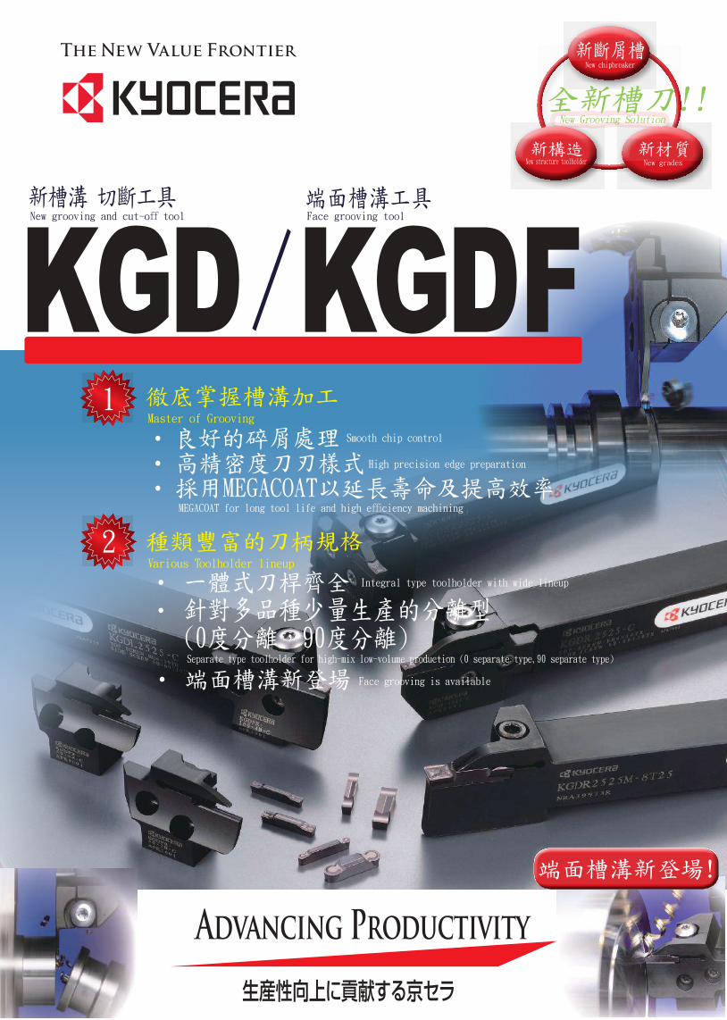
/KGDFMaster of Grooving
Smooth chip control
High precision edge preparation
fficiency machining
Various Toolholder lineup
Integral type toolholder with wide lineup
New g ing ff tool Face g ing tool
1
New chipbreaker
New gradesNew structure toolholder
KGD
一體式刀桿規格齊全
1 Master of Grooving
Application MapsExternal Grooving & Traversing
High FeedPH
Low Feed
GL
Low cutting resistance
GS
general
GM
feed
cutting resistance
High
Low
Low High
Cut-off
High Feed
PHgeneral
PM
feedLow High
cutting resistance
High
Low
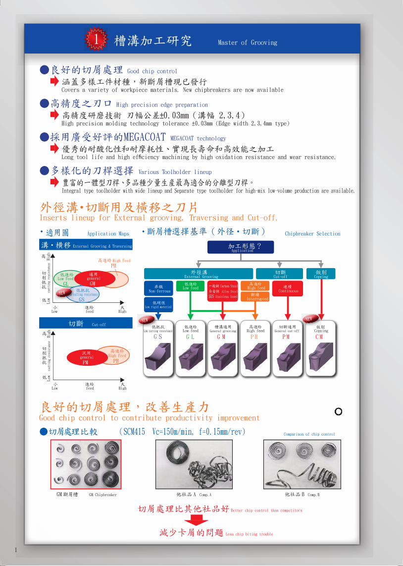
Good chip control
Covers a variety of workpiece materials. New chipbreakers are now available
High precision edge preparation
2,3,4High precision molding technology tolerance ±0.03mm (Edge width 2,3,4mm type)
MEGACOAT MEGACOAT technology
Long tool life and high efficiency machining by high oxidation resistance and wear resistance.
Various Toolholder lineup
Integral type toolholder with wide lineup and Separate type toolholder for high-mix low-volume production are available.
Good chip control to contribute productivity improvement
Comparison of chip control
G GM Chipbreaker A Comp.A B Comp.B
Better chip control than competitors
Less chip biting trouble
Chipbreaker Selection
Application
Carbon Steel
Alloy Steel
Stainless Steel
G M P HG L P MG S C M
Copying
High feedContinuous
Interrupted
External Grooving Cut-off
Low feed
Low feedLow cutting resistance General grooving High feed General cut-off Copying
Non-ferrous
Low rigid material
NEW
NEW
NEW
Inserts lineup for External grooving, Traversing and Cut-off.
1

MEGACOATLong tool life coating "MEGACOAT"
Features of MEGACOATHardness(GPa)
Oxidation temperature
40
30
20
10
0 200 400 600 800 1000 1200
TiCN
TiC
TiN
MEGACOAT
TiAlN
PR1225
PR1225: 1st. Recommendation for cut-off , grooving and traversing
PR1215
PR1215:With superior wear resistance, recommended for grooving and cut-off under the stable conditions.
1st. Recommendation for machining of cast iron.
Comparison of wear resistance Comparison of fracture resistance
0.000 20 40 60 80 100
0.05
0.10
0.15
0.20
(mm)
Flank wear
(min) Cutting time
Cutting Condition
Vc=200m/min,Comp.C
Comp.D
Comp.E
PR1215
Comp.F
Comp.G
PR1225
0.1 0.2 0.3 0.4 0.5 0.6
Feed
(Increase 0.03 by each pass)
High feed facingCompared feed rate at the point of edge fracture
Good wear resistance and fracture resistance
Stable cutting and long tool life at grooving and cut-off
Various lineup
Available two types of toolholder, Integral type and Separate type.
integral type
Various groove width and depth
separate typeSuitable for high-mix low-volume production
Toolholder and Inserts for Face grooving.
Only separate type is available for Face grooving
(Applicable for various groove diameter by replaceing blades)
Features of insert clamping system
W grip
Insert
holder
holder
The new "W grip" is applied for more rigid clamping and stable machining.
Prevent the insert from side-slip causing unstable machining and insert brakage
Upgrade the accuracy of indexability.
High rigidity, reliability and clamping strength.
GDFM GDFMS
Insert for GDFM/GDFMS is not compatible with KGD holder.
2
2 Various Toolholder lineup
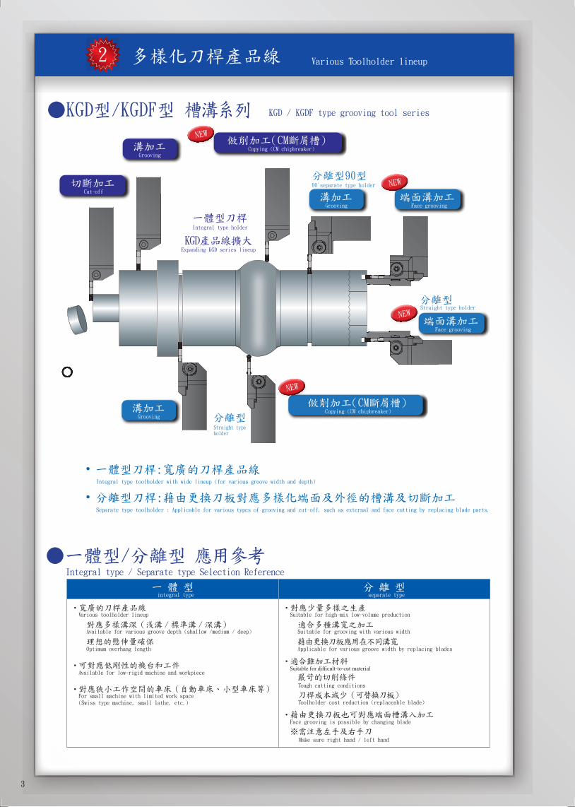
KGD / KGDF type grooving tool series
M
90°separate type holder
Straight type holder
M
Grooving
Grooving
Grooving
Cut-off
Copying (CM chipbreaker)
Integral type holder
Expanding KGD series lineup
Face grooving
Copying (CM chipbreaker)
Straight type holder
Face grooving
Integral type toolholder with wide lineup (for various groove width and depth)
Separate type toolholder : Applicable for various types of grooving and cut-off, such as external and face cutting by replacing blade parts.
Integral type / Separate type Selection Reference
integral type separate type
Var ious toolholder lineup
Available for various groove depth (shallow /medium / deep)
Optimum overhang length
Available for low-rigid machine and workpiece
For small machine with limited work space (Swiss type machine, small lathe, etc.)
Sui table for high-mix low-volume production
Suitable for grooving with various width
Applicable for various groove width by replacing blades
Tough cutting conditions
Toolholder cost reduction (replaceable blade)
Face grooving is possible by changing blade
Make sure right hand / left hand
NEW
NEW
NEW
NEW
3

Combination of Toololder & Blade (for grooving, traversing, cut-off)
Combination of Toololder & Blade (for Face Grooving)
② 90° 90°separate type
Toolholder
T Blade
)
)Left-hand Blade for Right-hand Toolholder, Right-hand Blade for Left- hand Toolholder
② (L) Left-hand
Toolholder hand is opposite as the one assembled.(Only for 0° separate type)
L Toolholder
- - Blade
)All face grooving toolholder (Right-hand) is applicable
R Toolholder
- - Blade
All face grooving toolholder (Left-hand) is applicable
R/L Toolholder
R/L T Blade
)Right-hand Blade for Right-hand Toolholder, Left-hand Blade for Left-hand Toolholder
)
① 0°separate type
① (R) Right-hand
° 0°separate type
90° 90°separate type
Right-hand
Toolholder
- - Blade
) )
) )Right-hand Blade (face grooving) for Right-hand Toolholder, Left-hand Blade (face grooving) for Left-hand Toolholder
4
0° 5°
5
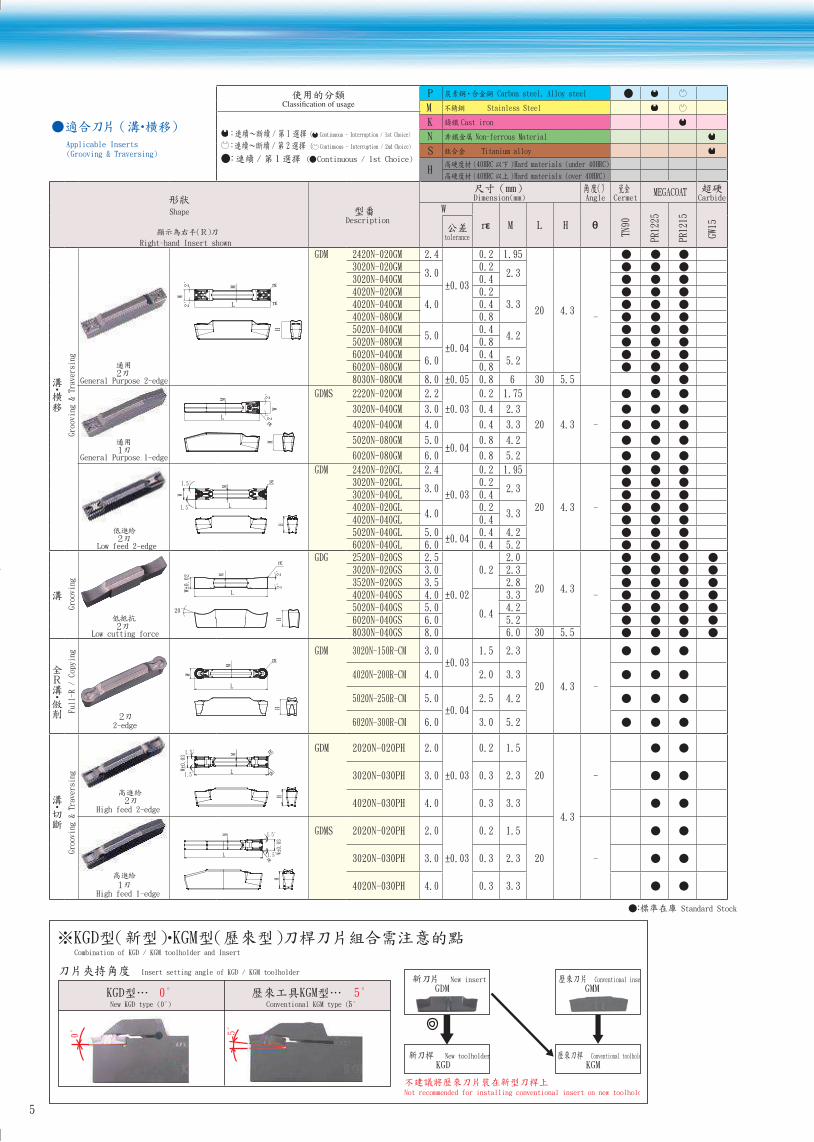
Applicable Inserts (Grooving & Traversing)
P Carbon steel, Alloy steel
M Stainless Steel
1/ ( Continuous - Interruption / 1st Choice)
/ ( Continuous - Interruption / 2nd Choice)
( Continuous / 1st Choice)
K Cast iron
N Non-ferrous Material
S Titanium alloy
H(40HRC ) Hard materials (under 40HRC)
(40HRC ) Hard materials (over 40HRC)
Shape
Right-hand Insert shown
Description
Dimension(mm)°
Angle CermetMEGACOAT
Carbide
W
rε M L H θ
TN90
PR1225
PR1215
GW15
tolerance
Grooving & Traversing
General Purpose 2-edge
2°2°
W
L
M rε
rε
H
GDM 2420N-020GM 2.4
±0.03
0.2 1.95
20 4.3-
3020N-020GM3.0
0.22.3
3020N-040GM 0.44020N-020GM
4.0 0.2
3.34020N-040GM 0.44020N-080GM 0.85020N-040GM
5.0 ±0.04
0.44.2
5020N-080GM 0.86020N-040GM
6.0 0.4
5.26020N-080GM 0.88030N-080GM 8.0 ±0.05 0.8 6 30 5.5
General Purpose 1-edge
H2°
2°
W
L
M
rε
GDMS 2220N-020GM 2.2
±0.03
0.2 1.75
20 4.3 -
3020N-040GM 3.0 0.4 2.3
4020N-040GM 4.0 0.4 3.3
5020N-080GM 5.0 ±0.04
0.8 4.2
6020N-080GM 6.0 0.8 5.2
Low feed 2-edge
L
rε
M
W
H
1.5°
1.5°
GDM 2420N-020GL 2.4
±0.03
0.2 1.95
20 4.3 -
3020N-020GL3.0
0.22.3
3020N-040GL 0.44020N-020GL
4.0 0.2
3.34020N-040GL 0.45020N-040GL 5.0
±0.040.4 4.2
6020N-040GL 6.0 0.4 5.2
Grooving
Low cutting force
H2°
2°
20°
W±0.02
L
M
rεGDG 2520N-020GS 2.5
±0.02
0.22.0
20 4.3-
3020N-020GS 3.0 2.33520N-020GS 3.5 2.84020N-040GS 4.0
0.4
3.35020N-040GS 5.0 4.26020N-040GS 6.0 5.28030N-040GS 8.0 6.0 30 5.5
Full-R / Copying
2-edge
H
W
L
M
rεGDM 3020N-150R-CM 3.0
±0.031.5 2.3
20 4.3 -4020N-200R-CM 4.0 2.0 3.3
5020N-250R-CM 5.0 ±0.04
2.5 4.2
6020N-300R-CM 6.0 3.0 5.2
Grooving & Traversing
High feed 2-edge
H
L
M rε
rεW±0.03
1.5°
1.5°
GDM 2020N-020PH 2.0
±0.03
0.2 1.5
20
4.3
-3020N-030PH 3.0 0.3 2.3
4020N-030PH 4.0 0.3 3.3
High feed 1-edge
M
L W±0.
03
1.5°
1.5°
H
rε
GDMS 2020N-020PH 2.0
±0.03
0.2 1.5
20 -3020N-030PH 3.0 0.3 2.3
4020N-030PH 4.0 0.3 3.3
Standard Stock
New insert
GDM0° 5°New KGD type (0°) Conventional KGM type (5°)
Not recommended for installing conventional insert on new toolholder.
Conventional insert
GMM
New toolholder
KGDConventional toolholder
KGM
Insert setting angle of KGD / KGM toolholder
Combination of KGD / KGM toolholder and Insert
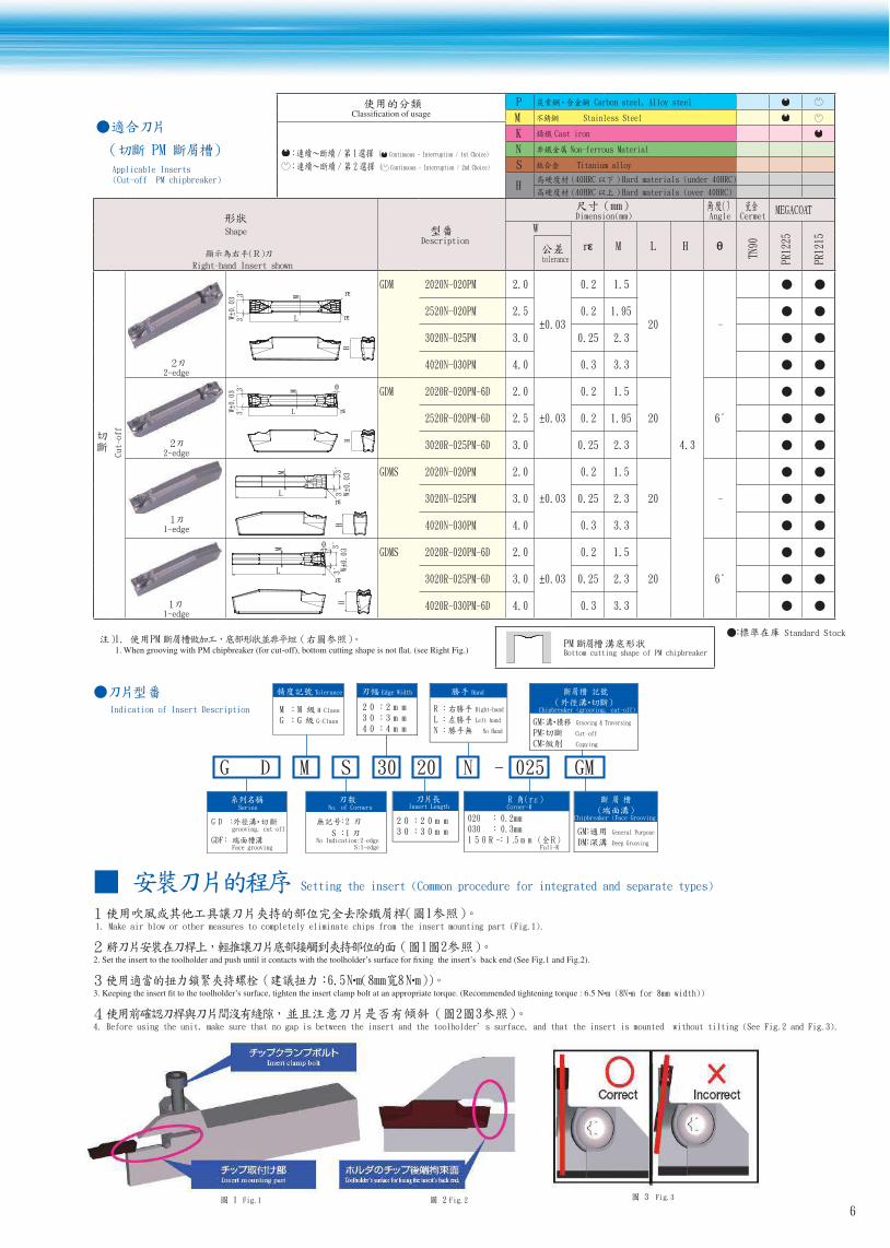
PM Applicable Inserts (Cut-off PM chipbreaker)
P Carbon steel, Alloy steel
M Stainless Steel
1/ ( Continuous - Interruption / 1st Choice)
/ 2 ( Continuous - Interruption / 2nd Choice)
K Cast iron
N Non-ferrous Material
S Titanium alloy
H(40HRC ) Hard materials (under 40HRC)
(40HRC ) Hard materials (over 40HRC)
Shape
Right-hand Insert shown
Description
Dimension(mm)°
Angle CermetMEGACOAT
W
rε M L H θ
TN90
PR1225
PR1215
tolerance
Cut-off
2-edge
H
3°
3°W±0.03
L
M rε
rε
GDM 2020N-020PM 2.0
±0.03
0.2 1.5
20
4.3
-2520N-020PM 2.5 0.2 1.95
3020N-025PM 3.0 0.25 2.3
4020N-030PM 4.0 0.3 3.3
2-edge
H
L
M
rε
3°
3°W±0.03
θ GDM 2020R-020PM-6D 2.0
±0.03
0.2 1.5
20 6°2520R-020PM-6D 2.5 0.2 1.95
3020R-025PM-6D 3.0 0.25 2.3
1-edge
H
rεL
M
3°3°
W±0.03
GDMS 2020N-020PM 2.0
±0.03
0.2 1.5
20 -3020N-025PM 3.0 0.25 2.3
4020N-030PM 4.0 0.3 3.3
1-edge
H
L
M
rε
θ
3°3°
W±0.
03 GDMS 2020R-020PM-6D 2.0
±0.03
0.2 1.5
20 6°3020R-025PM-6D 3.0 0.25 2.3
4020R-030PM-6D 4.0 0.3 3.3
Standard Stock
Indication of Insert Description
Setting the insert (Common procedure for integrated and separate types)
1. Make air blow or other measures to completely eliminate chips from the insert mounting part (Fig.1).
6.5 m mm (8N m for 8mm width))
4. Before using the unit, make sure that no gap is between the insert and the toolholder s surface, and that the insert is mounted without tilting (See Fig.2 and Fig.3).
G D M S 30 20 N - 025 GM
Tolerance
M M M-Class
G G G-Class
rCorner-R
020 0.2mm030 0.3mm
-R051 mm5.1 Full-R
Edge Width
mm2 02mm3 03mm4 04
Insert Length
mm02 02mm03 03
Chipbreaker (grooving, cut-off)
GM Grooving & Traversing
P Cut-off
C Copying
Chipbreaker (Face Grooving)
G General Purpose
D Deep Grooving
Hand
R Right-hand
L Left-hand
N No Hand
Series
DG grooving, cut-off
GDF Face grooving
2
1 S No Indication:2-edge
S:1-edge
No. of Corners
M Bottom cutting shape of PM chipbreaker
Insert clamp bolt
Insert mounting part
Fig.1 Fig.2 Fig.3
6
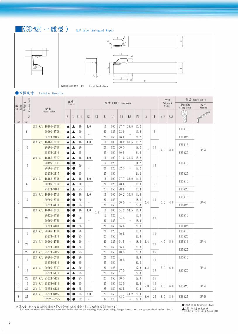
KGD type (integral type)
L3
H2H3
W
L1
A
F1
T
L2
h
BH1
L3
H2H3
W
L1
A
F1
T
L2
h
BH1
Toolholder dimensions
Width
Max.
Gro
ovin
g De
pth
Description
Stock Dimension
W Width
Spare parts
Clamp Bolt Wrench
R L H1=h H2 H3 B L1 L2 L3 F1 A T MIN MAX
2
6
KGD R/L 1616H-2T06 16 4.0
9.5
16 100 27.7 28.0 15.2
1.7
6
2.0 3.0
HH5X16
LW-4
2020K-2T06 20-
20 125 28.0 -
19.2
2525M-2T06 25 25 150 28.0 24.2 HH5X25
10
KGD R/L 1616H-2T10 16 4.0 16 100 30.2 30.5 15.2
10HH5X16
2020K-2T10 20-
20 125 30.5 -
19.2
2525M-2T10 25 25 150 30.5 24.2 HH5X25
17
KGD R/L 1616H-2T17 16 4.0 16 100 31.2 31.5 15.2
17HH5X162012K-2T17
20-
12 125
32.5 -
11.2
2020K-2T17 20 125 19.2
2525M-2T17 25 25 150 24.2 HH5X25
3
6
KGD R/L 1616H-3T06 16 4.0 16 100 27.7 28.0 14.8
2.4
6
3.0 4.0
HH5X16
LW-4
2020K-3T06 20-
20 125 28.0 -
18.8
2525M-3T06 25 25 150 28.0 23.8 HH5X25
10
KGD R/L 1616H-3T10 16 4.0 16 100 30.2 30.5 14.8
10HH5X16
2020K-3T10 20-
20 12530.5 -
18.8
2525M-3T10 25 25 150 23.8 HH5X25
20
KGD R/L 1616H-3T20 16 4.0 16 100 34.2 34.5 14.8
20HH5X162012K-3T20
20-
12 12534.5
-
10.8
2020K-3T20 20 125 18.8
2525M-3T20 25 25 150 35.5 23.8 HH5X25
4
10KGD R/L 2020K-4T10 20
-
20 12530.5
-
18.3
3.4
10
4.0 5.0
HH5X16
LW-4
2525M-4T10 25 25 150 23.3 HH5X25
20KGD R/L 2020K-4T20 20 20 125 34.5 18.3
20HH5X16
2525M-4T20 25 25 150 35.5 23.3 HH5X25
25 KGD R/L 2525M-4T25 25 25 150 40.5 23.3 25
5
10KGD R/L 2020K-5T10 20
-
20 12530.5
-
17.8
4.4
10
5.0 6.0
HH5X16
LW-4
2525M-5T10 25 25 150 22.8
HH5X2517KGD R/L 2020K-5T17 20 20 125
37.517.8
172525M-5T17 25 25 150 22.8
25 KGD R/L 2525M-5T25 25 25 150 40.5 22.8 25
615 KGD R/L 2525M-6T15 25
-25 150 32.5
-22.4
5.315
6.0 6.0 HH5X25 LW-430 KGD R/L 2525M-6T30 25 25 150 45.5 22.4 30
8 25KGD R/L 2525M-8T25 25 7.0 25 150
43.344.2 22.0
6.0 25 8.0 8.0 HH6X25 LW-53232P-8T25 32 - 32 170 - 29.0
Standard Stock
Scheduled to be in stock August 2011T dimension shows the distance from the Toolholder to the cutting edge.(When using 2-edge insert, set the groove depth under 18mm.)
Right-hand shown
7
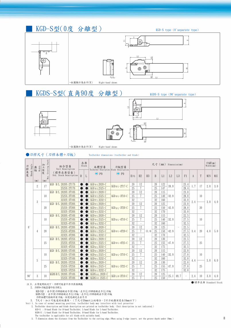
KGD-S type (0°separate type)
B
T
W
F1
h
L2
H3
H2
L1
H1
A
B
T
W
F1
h
L2
H3
H2
L1
H1
A
KGDS-S type (90°separate type)
H1
H2H3
A
L1L2
B
T
L3
h
H1
H2H3
A
L1L2
B
T
L3
h
Toolholder dimensions (toolholder and blade)
Shank Angle
Width
Max. Grooving Depth
Unit Description
Std. Stock Description
Stock
Toolholder Description
P9
Blade Description
P9
Dimension(mm)W
Width(mm)
R L H1=h H2 H3 B L1 L2 L3 F1 A T MIN MAX
0°
2 17KGD R/L 2020X-2T17S KGD R/L 2020-C
KGD R/L-2T17-C20 12
11.6
20 12239.9
-
23.41.7 17 2.0 3.0
2525X-2T17S KGD R/L 2525-C 25 7 25 147 28.4
3
10
KGD R/L 2020X-3T10S KGD 2020-C
KGD -3T10-C
20 12 20 115
32.9
23.0
2.4
10
3.0 4.0
2525X-3T10S KGD 2525-C 25 7 25 140 28.0
3232X-3T10S KGD 3232-C 32 - 32 160 33.0
20
KGD R/L 2020X-3T20S KGD 2020-C
KGD -3T20-C
20 12 20 125
42.9
23.0
202525X-3T20S KGD 2525-C 25 7 25 150 28.0
3232X-3T20S KGD 3232-C 32 - 32 170 33.0
4
10
KGD R/L 2020X-4T10S KGD 2020-C
KGD -4T10-C
20 12 20 115
32.9
22.5
3.4
10
4.0 5.0
2525X-4T10S KGD 2525-C 25 7 25 140 27.5
3232X-4T10S KGD 3232-C 32 - 32 160 32.5
20
KGD R/L 2020X-4T20S KGD 2020-C
KGD -4T20-C
20 12 20 125
42.9
22.5
202525X-4T20S KGD 2525-C 25 7 25 150 27.5
3232X-4T20S KGD 3232-C 32 - 32 170 32.5
25
KGD R/L 2020X-4T25S KGD 2020-C
KGD -4T25-C
20 12 20 130
47.9
22.5
252525X-4T25S KGD 2525-C 25 7 25 155 27.5
3232X-4T25S KGD 3232-C 32 - 32 175 32.5
5
10
KGD R/L 2020X-5T10S KGD 2020-C
KGD -5T10-C
20 12 20 115
32.9
22.0
4.4
10
5.0 6.0
2525X-5T10S KGD 2525-C 25 7 25 140 27.0
3232X-5T10S KGD 3232-C 32 - 32 160 32.0
25
KGD R/L 2020X-5T25S KGD 2020-C
KGD -5T25-C
20 12 20 130
47.9
22.0
252525X-5T25S KGD 2525-C 25 7 25 155 27.0
3232X-5T25S KGD 3232-C 32 - 32 175 32.0
90° 3 10KGDS R/L 2020X-3T10S KGDS 2020-C
KGD
R/L
R/L
R/L
R/L
R/L
R/L
R/L
R/L
R/L
R/L
R/L
R/L
R/L
R/L
R/L
R/L
R/L
-3T10-C20 12 20 125
25.1 49.7 - 2.4 10 3.0 4.02525X-3T10S KGDS 2525-C 25 7 25 150
Standard Stock1. 2.
Note) 1. In case of normal mounting position, toolholder body may interfere with tool presetter
2. Toolholder description and blade description are printed on toolholder body. (Unit description is not indicated.)
KGD-S : R-hand Blade for R-hand Toolholder, L-hand Blade for L-hand Toolholder.
KGDS-S : L-hand Blade for R-hand Toolholder, R-hand Blade for L-hand Toolholder.
The toolholder is applicable for all blade with suitable hand.
3. T dimension shows the distance from the Toolholder to the cutting edge.(When using 2-edge insert, set the groove depth under 18mm.)
Right-hand shown
Right-hand shown
8
R/L
R/L
R/L
R/L
R/L
R/L
R/L
R/L
R/L
R/L
R/L
R/L
R/LL/R

9
Spare parts
Unit Description
Spare parts
Clamp bolt (For Insert Clamp) Fixing bolt(For Blade) Wrench
KGD $・・・・・S BH6X10TR SB-60120TR LTW-25
Setting the blade (Separate-type toolholder)
1. Make air blow or other measures to completely eliminate chips and dusts from the serration part (See Fig.4).
2. Fit closely the serration joints of the blade and toolholder (See Fig.5).
4. Set the insert after setting the blade.
Fig.4
Blade
Serration joint
Toolholder
Fig.5
Insert clamp bolt
Blade
Toolholder
No gap between blade and
toolholder
0°separate type shape
Right-hand Shown
Description of Toolholder
Stock Dimension(mm)
R L L B H1
L
H1B KGD R/L 2020-C 104 20 20
2525-C 129 25 25
3232-C 149 32 32
90°separate type shape
Right-hand Shown
Description of Toolholder
Stock Dimension(mm)
R L L B H1
L
H1B
KGDS R/L 2020-C 122 20 20
2525-C 147 25 25
Blade shape
Right-hand Shown
Description of Blade
Stock Dimension(mm)
R L L T W
L
41.5
W
T KGD R/L -2T17-C 51.2 17.2 1.7
-3T10-C 44.2 10.2 2.4
-3T20-C 53.2 20.2 2.4
-4T10-C 44.2 10.2 3.4
-4T20-C 54.2 20.2 3.4
-4T25-C 59.2 25.2 3.4
-5T10-C 44.2 10.2 4.4
-5T25-C 59.2 25.2 4.4
Standard Stock
2
3
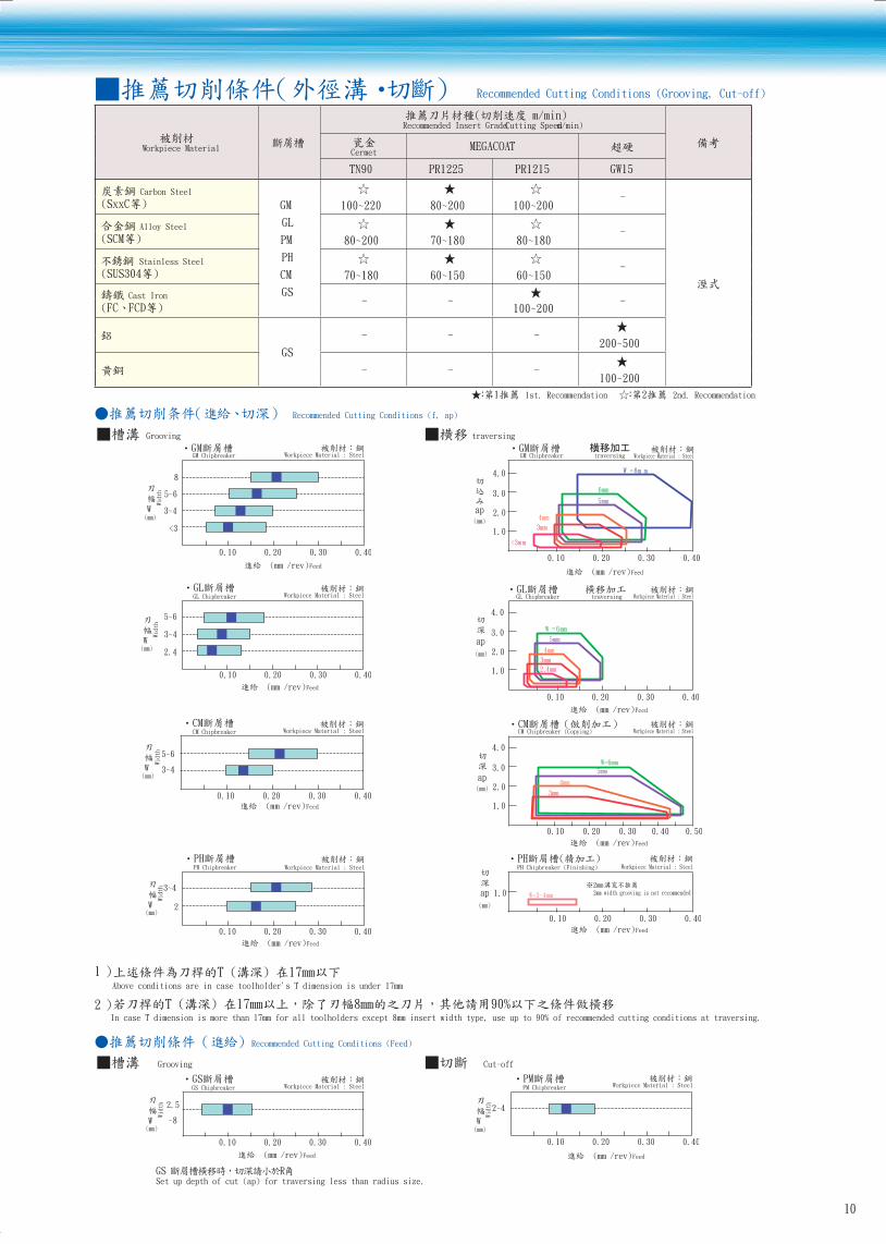
Recommended Cutting Conditions (Grooving, Cut-off)
Workpiece Material
Recommended Insert Grade (Cutting Speed m/min)
CermetMEGACOAT
TN90 PR1225 PR1215 GW15
Carbon Steel
GM
GL
PM
PH
CM
GS
-100~220 80~200 100~200
Alloy Steel-
80~200 70~180 80~180
Stainless Steel-
70~180 60~150 60~150
Cast Iron- - -
100~200
GS
- - -200~500
- - -100~200
1st. Recommendation 2nd. Recommendation
Recommended Cutting Conditions (f, ap)
Grooving traversing
3~4
5~6
<3
8
0.10 0.20 0.30 0.40
G GM Chipbreaker Workpiece Material : Steel
/rev) Feed
(mm)W
Width
2.0
3.0
1.0
4.0
0.10 0.20 0.30 0.40
GM Chipbreaker traversing
ap(mm)
Workpiece Material : Steel
/rev) Feed
W =8m m
6mm
5mm
4mm
3mm
<3mm
3~4
5~6
2.4
0.10 0.20 0.30 0.40
GL Chipbreaker Workpiece Material : Steel
/rev) Feed
(mm)W
Widt
h
2.0
3.0
1.0
4.0
0.10 0.20 0.30 0.40
GL Chipbreaker traversing
ap(mm)
Workpiece Material : Steel
/rev) Feed
W =6mm
5mm
4mm
3mm
2.4mm
3~4
0.10 0.20 0.30 0.40
CM Chipbreaker
5~6
Workpiece Material : Steel
/rev) Feed
(mm)W
Widt
h
2.0
3.0
1.0
4.0
0.10 0.20 0.30 0.40 0.50
CM Chipbreaker (Copying)
W=6mm
5mm
4mm
3mm
ap(mm)
Workpiece Material : Steel
/rev) Feed
3~4
2
0.10 0.20 0.30 0.40
PH Chipbreaker Workpiece Material : Steel
/rev) Feed
(mm)W
Widt
h
1.0
0.10 0.20 0.30 0.40
PH Chipbreaker (Finishing)
W=3-4mm
2mm 2mm width grooving is not recommendedap
(mm)
Workpiece Material : Steel
/rev) Feed
1Above conditions are in case toolholder's T dimension is under 17mm
2 In case T dimension is more than 17mm for all toolholders except 8mm insert width type, use up to 90% of recommended cutting conditions at traversing.
Recommended Cutting Conditions (Feed)
Grooving Cut-off
2.5
~8
0.10 0.20 0.30 0.40
GS Chipbreaker Workpiece Material : Steel
/rev) Feed
(mm)W
Widt
h
2~4
0.10 0.20 0.30 0.40
PM Chipbreaker Workpiece Material : Steel
/rev) Feed
(mm)W
Widt
h
GS Set up depth of cut (ap) for traversing less than radius size.
10
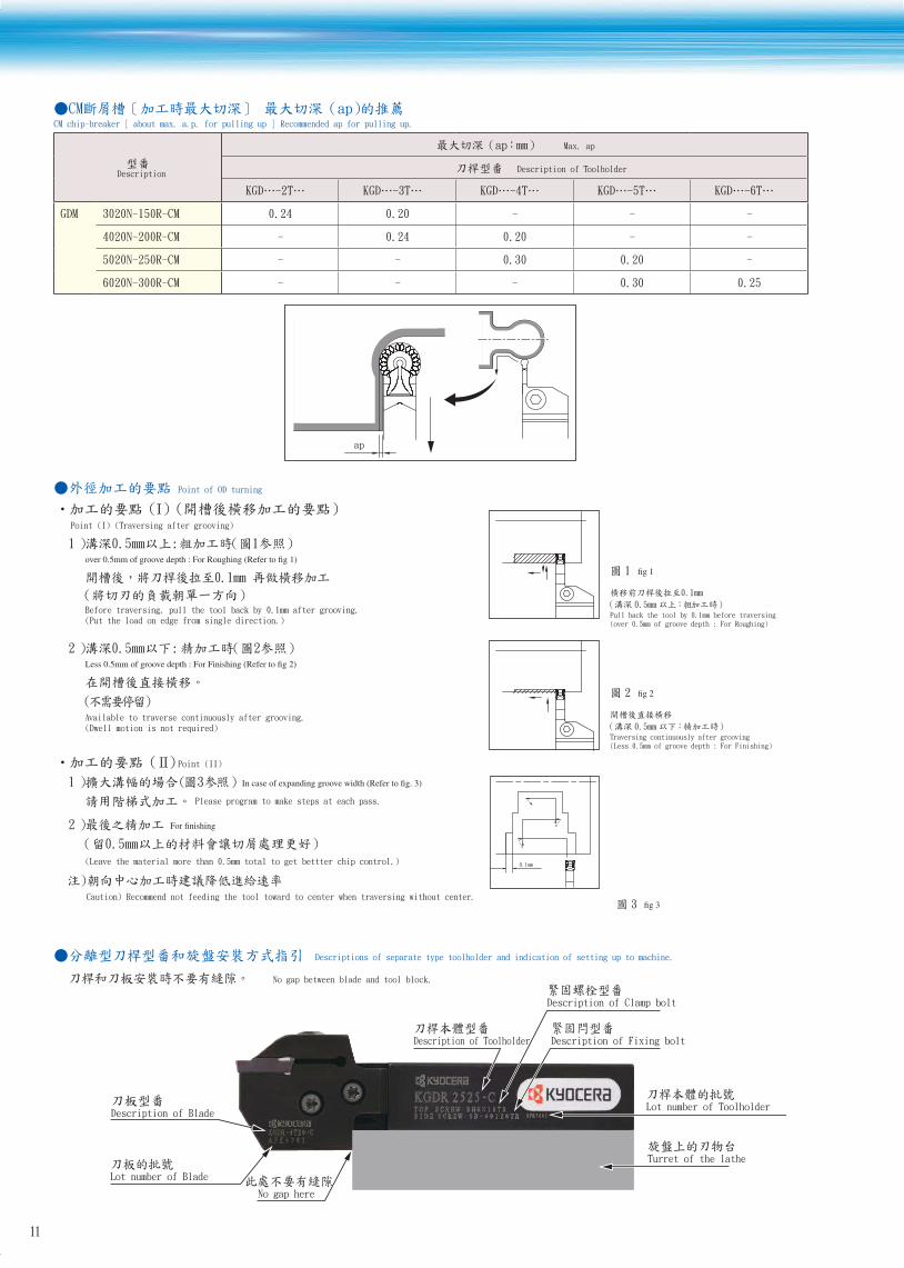
CM chip-breaker [ about max. a.p. for pulling up ] Recommended ap for pulling up.
Description
mm Max. ap
Description of Toolholder
KGD…-2T… KGD…-3T… KGD…-4T… KGD…-5T… KGD…-6T…
GDM 3020N-150R-CM 0.24 0.20 - - -
4020N-200R-CM - 0.24 0.20 - -
5020N-250R-CM - - 0.30 0.20 -
6020N-300R-CM - - - 0.30 0.25
ap
Point of OD turning
Point (I) (Traversing after grooving)
1
Before traversing, pull the tool back by 0.1mm after grooving. (Put the load on edge from single direction.)
1
Pull back the tool by 0.1mm before traversing (over 0.5mm of groove depth : For Roughing)
2
Available to traverse continuously after grooving. (Dwell motion is not required)
2
Traversing continuously after grooving(Less 0.5mm of groove depth : For Finishing)
Point (II)
31
Please program to make steps at each pass.
2
(Leave the material more than 0.5mm total to get bettter chip control.)
Caution) Recommend not feeding the tool toward to center when traversing without center.
0.1mm
3
Descriptions of separate type toolholder and indication of setting up to machine.
No gap between blade and tool block.
Description of Blade
Lot number of Blade
No gap here
Description of Toolholder
Description of Clamp bolt
Description of Fixing bolt
Lot number of Toolholder
Turret of the lathe
11

KGDF Face grooving tool
P Carbon steel, Alloy steel
M Stainless Steel
1/ ( Continuous - Interruption / 1st Choice)
/ ( Continuous - Interruption / 2nd Choice)
(● Continuous / 1st Choice)
K Cast iron
N Non-ferrous Material
S Titanium alloy
HC ) Hard materials (under 40HRC)
C ) Hard materials (over 40HRC)
Shape Description
Dimension(mm) CermetMEGACOAT
Wrε M L H
TN90
PR1225
PR1215
tolerance
Grooving & Traversing
2-edge
W2°
2°
rε
M
L
H
GDFM 3020N-030GM 3.0 ±0.03
0.3 2.3
20 4.34020N-040GM 4.0
0.4
3.3
5020N-040GM 5.0 ±0.04
4.2
6020N-040GM 6.0 5.2
Deep Grooving, traversing
2-edge
rε
W2°
2°M
L
H
GDFM 3020N-030DM 3.0 ±0.03
0.3 2.3
20 4.34020N-040DM 4.0
0.4
3.3
5020N-040DM 5.0 ±0.04
4.2
6020N-040DM 6.0 5.2
1-edge
rε
2°H
L
M
W2°
GDFMS 3020N-030DM 3.0 ±0.03
0.3 2.3
20 4.34020N-040DM 4.0
0.4
3.3
5020N-040DM 5.0 ±0.04
4.2
6020N-040DM 6.0 5.2
Standard Stock
Scheduled to be in stock August 2011
Advantages of chipbreaker
MDeep Grooving, DM chipbreaker
Curved front edge line
Front edge wall
Improves chip control at shouldering
Smooth wall design from front
edge to back side
Changes chip shape and stabilizes chip evacuation direction
Gently raised wall shape
Constantly curled chips
Flat cutting edge line
Improves chip control
Stabilizes chip shape
Curved front edge line
Stabilizes chip shape
Smooth wall design from front edge to back side
Reduces cutting resistanceChanges chip shape and stabilizes chip evacuation direction
Concave portion
Changes chip shape smoothly
Convex wall
GMGeneral Purpose, GM chipbreaker
Changes chip shape and stabilizes chip evacuation direction
Comparison of chip control (GM chipbreaker)
Face grooving
0.05 0.08 0.1
/rev) Feed
Groove wall machining
0.5
1.0
0.1 0.15 0.2
/rev) Feed
(mm)
Width of cut
Turning
0.05 0.1
0.2
0.5
0.8
0.15
ap
/rev) Feed
(mm)
< > Cutting Condition
Vc=150m/min f =0.05~ 0.1mm/rev GDFM5020N-040GM SCM415 Wet
P.6See page 6 for indication of insert description
12
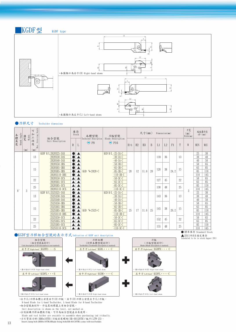
KGDF type
L1
T
L2
F1H3
W
H2
BH1 h
L1
T
L2
F1H3
W
H2
BH1h
Toolholder dimensions
Shank Angle
Width
Max. Grooving Depth
Unit Description
Stock
Toolholder Description
P9
Blade Description
P16
Dimension(mm)Width(mm)
øD (mm)
R L H1=h H2 H3 B L1 L2 F1 T W MIN MAX
0° 3
13KGDF R/L 2020X25-3AS
KGD 2020-C
KGD R/L -25-3A-C
20 12 11.6 20
118 36
24.2
13
3
25 302020X30-3AS -30-3A-C 30 402020X40-3AS -40-3A-C 40 50
15
2020X50-3BS -50-3B-C
120 38 15
50 652020X65-3BS -65-3B-C 65 852020X85-3BS -85-3B-C 85 1102020X110-3BS -110-3B-C 110 145
222020X50-3CS -50-3C-C
127 45 2250 65
2020X65-3CS -65-3C-C 65 85
252020X85-3CS -85-3C-C
130 48 2585 110
2020X110-3CS -110-3C-C 110 145
13KGDF R/L 2525X25-3AS
KGD 2525-C
KGD R/L -25-3A-C
25 17 11.6 25
143 36
29.2
1325 30
2525X30-3AS -30-3A-C 30 402525X40-3AS -40-3A-C 40 50
15
2525X50-3BS -50-3B-C
145 38 15
50 652525X65-3BS -65-3B-C 65 852525X85-3BS -85-3B-C 85 1102525X110-3BS -110-3B-C 110 145
222525X50-3CS -50-3C-C
152 45 2250 65
2525X65-3CS -65-3C-C 65 85
252525X85-3CS -85-3C-C
155 48 2585 110
2525X110-3CS -110-3C-C 110 145 Standard Stock
Scheduled to be in stock August 2011 Indication of KGDF unit description
Unit description (Unit description is not marked) Toolholder (Toolholder description is marked) Blade (Blade description is marked)
Right-hand KGDFR S Left-hand KGDL -C Right-hand KGDFR -C
Left-hand KGDFL S Right-hand KGDR -C Left-hand KGDFL -C
(L) R-hand Blade for L-hand Toolholder, L-hand Blade for R-hand Toolholder
Unit description is shown on the lavel, not marked on
Blade and tool holder are avaiable to assemble when purchasing ind ividually.
/
Left-hand shown
Right-hand shown
Right-hand shown Left-hand shown Right-hand shown
Left-hand shown Right-hand shown Left-hand shown
13
Toolholder dimensionsShank Angle
Width
Max.
Gro
ovin
gDep
thUnit Description
StockToolholder Description
P9
Blade Description
P16
Dimension(mm)Width(mm)
øD (mm)
R L H1=h H2 H3 B L1 L2 F1 T W MIN MAX
0°
4
13 KGDF R/L 2020X25-4AS
KGD 2020-C
KGDF R/L -25-4A-C
20 12 11.6 20
118 36
24.2
13
4
25 35
15
2020X35-4BS -35-4B-C
120 38 15
35 502020X50-4BS -50-4B-C 50 702020X70-4BS -70-4B-C 70 1002020X100-4BS -100-4B-C 100 1502020X150-4BS -150-4B-C 150 2202020X220-4BS -220-4B-C 220
25
2020X35-4CS -35-4C-C
130 48 25
35 502020X50-4CS -50-4C-C 50 702020X70-4CS -70-4C-C 70 1002020X100-4CS -100-4C-C 100 1502020X150-4CS -150-4C-C 150 2202020X220-4CS -220-4C-C 220
13 KGDF R/L 2525X25-4AS
KGD 2525-C
KGDF R/L -25-4A-C
25 17 11.6 25
143 36
29.2
13 25 35
15
2525X35-4BS -35-4B-C
145 38 15
35 502525X50-4BS -50-4B-C 50 702525X70-4BS -70-4B-C 70 1002525X100-4BS -100-4B-C 100 1502525X150-4BS -150-4B-C 150 2202525X220-4BS -220-4B-C 220
25
2525X35-4CS -35-4C-C
155 48 25
35 502525X50-4CS -50-4C-C 50 702525X70-4CS -70-4C-C 70 1002525X100-4CS -100-4C-C 100 1502525X150-4CS -150-4C-C 150 2202525X220-4CS -220-4C-C 220
5
15
KGDF R/L 2020X25-5BS
KGD 2020-C
KGDF R/L -25-5B-C
20 12 11.6 20
120 38
24.2
15
5
25 352020X35-5BS -35-5B-C 35 502020X50-5BS -50-5B-C 50 752020X75-5BS -75-5B-C 75 1152020X115-5BS -115-5B-C 115 1802020X180-5BS -180-5B-C 180 2352020X235-5BS -235-5B-C 235
20 2020X25-5CS -25-5C-C 125 43 20 25 35
25
2020X35-5CS -35-5C-C
130 48 25
35 502020X50-5CS -50-5C-C 50 752020X75-5CS -75-5C-C 75 1152020X115-5CS -115-5C-C 115 1802020X180-5CS -180-5C-C 180 2352020X235-5CS -235-5C-C 235
15
KGDF R/L 2525X25-5BS
KGD 2525-C
KGDF R/L -25-5B-C
25 17 11.6 25
145 38
29.2
15
25 352525X35-5BS -35-5B-C 35 502525X50-5BS -50-5B-C 50 752525X75-5BS -75-5B-C 75 1152525X115-5BS -115-5B-C 115 1802525X180-5BS -180-5B-C 180 2352525X235-5BS -235-5B-C 235
20 2525X25-5CS -25-5C-C 150 43 20 25 35
252525X35-5CS -35-5C-C
155 48 2535 50
2525X50-5CS -50-5C-C 50 75
32
2525X75-5DS -75-5C-C
162 55 32
75 1152525X115-5DS -115-5C-C 115 1802525X180-5DS -180-5C-C 180 2352525X235-5DS -235-5C-C 235
Standard Stock
Scheduled to be in stock August 2011
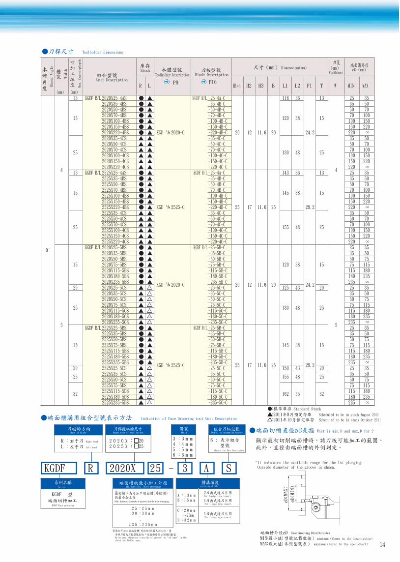
Scheduled to be in stock October 2011 Indication of Face Grooving tool Unit Description
KGDF R 2020X 25 -
grooving depth
mm31 Amm51 B
For 2-edge type insert
For 1-edge type insert
mm02 C 25mm
mm23 DFor 1-edge type insert
Shank size of tool holder
X0202 20 X5202 25
mm52 52 mm03 03
mm532 532
Min.Bore Dia. (Face grooving)
Width
mm3 3mm4 4mm5 5mm6 6
Symbol of assembled holder
Indicate the Unit Description
Hand of Blade
R Right-hand
L Left-hand
3 A S
Series
KGDF Face grooving
KGDF
Refer max. diameter (outside of groove) to "oD (mm)" in thechart for holder spec.
ø D What is min.D and max.D for ?
"It indicates the available range for the 1st plunging. Outside diameter of the groove is shown.
øD(MIN)
øD(MAX)
Face Grooving Dia.(Out side)
MI minimum (Shown in the description)
MA maximum (Refer to the spec chart) 14
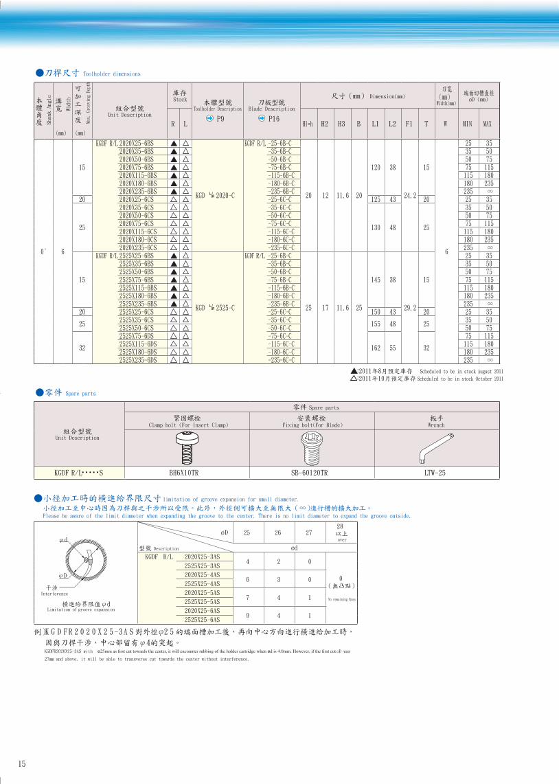
Toolholder dimensions
Shank Angle
Width
Max.
Gro
ovin
g De
pth
Unit Description
Stock
Toolholder Description
P9
Blade Description
P16
Dimension(mm)Width(mm)
øD (mm)
R L H1=h H2 H3 B L1 L2 F1 T W MIN MAX
0° 6
15
KGDF R/L 2020X25-6BS
KGD 2020-C
KGDF R/L -25-6B-C
20 12 11.6 20
120 38
24.2
15
6
25 352020X35-6BS -35-6B-C 35 502020X50-6BS -50-6B-C 50 752020X75-6BS -75-6B-C 75 1152020X115-6BS -115-6B-C 115 1802020X180-6BS -180-6B-C 180 2352020X235-6BS -235-6B-C 235
20 2020X25-6CS -25-6C-C 125 43 20 25 35
25
2020X35-6CS -35-6C-C
130 48 25
35 502020X50-6CS -50-6C-C 50 752020X75-6CS -75-6C-C 75 1152020X115-6CS -115-6C-C 115 1802020X180-6CS -180-6C-C 180 2352020X235-6CS -235-6C-C 235
15
KGDF R/L 2525X25-6BS
KGD 2525-C
KGDF R/L -25-6B-C
25 17 11.6 25
145 38
29.2
15
25 352525X35-6BS -35-6B-C 35 502525X50-6BS -50-6B-C 50 752525X75-6BS -75-6B-C 75 1152525X115-6BS -115-6B-C 115 1802525X180-6BS -180-6B-C 180 2352525X235-6BS -235-6B-C 235
20 2525X25-6CS -25-6C-C 150 43 20 25 35
252525X35-6CS -35-6C-C
155 48 2535 50
2525X50-6CS -50-6C-C 50 75
32
2525X75-6DS -75-6C-C
162 55 32
75 1152525X115-6DS -115-6C-C 115 1802525X180-6DS -180-6C-C 180 2352525X235-6DS -235-6C-C 235
Scheduled to be in stock August 2011
Scheduled to be in stock October 2011
Spare parts
Unit Description
Spare parts
Clamp bolt (For Insert Clamp) Fixing bolt(For Blade) Wrench
KGDF R/L・・・・・S BH6X10TR SB-60120TR LTW-25
limitation of groove expansion for small diameter.
Please be aware of the limit diameter when expanding the groove to the center. There is no limit diameter to expand the groove outside.
Interference
D
dLimitation of groove expansion
døD 25 26 27
28
over
Description ød
KGDF R/L 2020X25-3AS 4 2 0
0
No remaining Boss
2525X25-3AS
2020X25-4AS 6 3 0
2525X25-4AS
2020X25-5AS 7 4 1
2525X25-5AS
2020X25-6AS 9 4 1
2525X25-6AS
52SA3-52X0202RFDGK
KGDFR2020X25-3AS with ø ø oD was
27mm and above, it will be able to transverse cut towards the center without interference.
15

16
Blade dimensions
Shape Description of Blade
Stock Dimension(mm)Face Grooving Dia.
øD (mm) Applicable Inserts
P12
Description or Toolholder
P9R L L T A MIN MAX
T
L
41.5
A
Right-hand Shown
KGDF R/L -25-3A-C
47.35 13
2
25 30
GDFM 3020N-030GM
GDFM 3020N-030DM
GDFMS 3020N-030DM
KGD -C
KGDS R/L•••-C
-30-3A-C 30 40
-40-3A-C 40 50
-50-3B-C
49.35 15
50 65
-65-3B-C 65 85
-85-3B-C 85 110
-110-3B-C 110 145
-50-3C-C56.35 22
50 65
-65-3C-C 65 85
-85-3C-C59.35 25
85 110
-110-3C-C 110 145
KGDF R/L -25-4A-C 47.35 13
3
25 35
GDFM 4020N-040GM
GDFM 4020N-040DM
GDFMS 4020N-040DM
-35-4B-C
49.35 15
35 50
-50-4B-C 50 70
-70-4B-C 70 100
-100-4B-C 100 150
-150-4B-C 150 220
-220-4B-C 220 ∞
-35-4C-C
59.35 25
35 50
-50-4C-C 50 70
-70-4C-C 70 100
-100-4C-C 100 150
-150-4C-C 150 220
-220-4C-C 220 ∞
KGDF R/L -25-5B-C
49.35 15
4
25 35
GDFM 5020N-040GM
GDFM 5020N-040DM
GDFMS 5020N-040DM
-35-5B-C 35 50
-50-5B-C 50 75
-75-5B-C 75 115
-115-5B-C 115 180
-180-5B-C 180 235
-235-5B-C 235 ∞
-25-5C-C
L/R •••
54.35 20 25 35
-35-5C-C
59.35 25
35 50
-50-5C-C 50 75
-75-5C-C 75 115
-115-5C-C 115 180
-180-5C-C 180 235
-235-5C-C 235 ∞
-75-5D-C
66.35 32
75 115
-115-5D-C 115 180
-180-5D-C 180 235
-235-5D-C 235 ∞
KGDF R/L -25-6B-C
49.35 15
5
25 35
GDFM 6020N-040GM
GDFM 6020N-040DM
GDFMS 6020N-040DM
-35-6B-C 35 50
-50-6B-C 50 75
-75-6B-C 75 115
-115-6B-C 115 180
-180-6B-C 180 235
-235-6B-C 235 ∞
-25-6C-C 54.35 20 25 35
-35-6C-C
59.35 25
35 50
-50-6C-C 50 75
-75-6C-C 75 115
-115-6C-C 115 180
-180-6C-C 180 235
-235-6C-C 235 ∞
-75-6D-C
66.35 32
75 115
-115-6D-C 115 180
-180-6D-C 180 235
-235-6D-C 235 ∞
Standard Stock
Scheduled to be in stock August 2011
Scheduled to be in stock October 2011 Indication of blade for face groove
KGDF R 25 - --
grooving depth
mm31 Amm51 B
For 2-edge type insert
For 1-edge type insert
mm02 C 25mm
mm23 DFor 1-edge type insert
mm52 52 mm03 03
mm532 532
Min.Bore Dia. (Face grooving)
Indicates avairable outside groove dia. for the 1st plunging.
Width
mm3 3mm4 4mm5 5mm6 6
Symbol
C :
Shank Height for 20mm/25mm square shank
Hand of Blade
R Right-hand
L Left-hand
3 A C
Series
KGDF Face grooving
KGDF
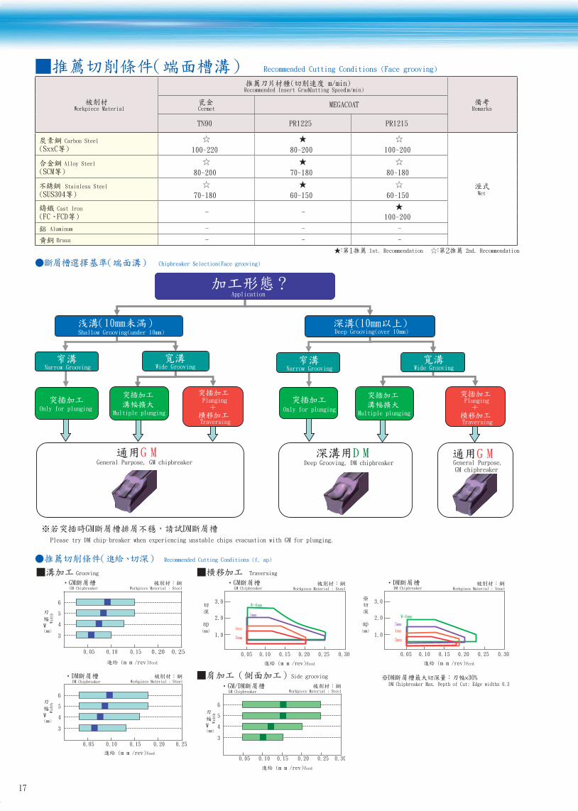
Recommended Cutting Conditions (Face grooving)
Workpiece Material
Recommended Insert Grade Cutting Speed (m/min)
RemarksCermetMEGACOAT
TN90 PR1225 PR1215
Carbon Steel
Wet
100~220 80~200 100~200
Alloy Steel
80~200 70~180 80~180
Stainless Steel
70~180 60~150 60~150
Cast Iron- -
100~200
- - -
- - -
1st. Recommendation 2nd. Recommendation
Chipbreaker Selection(Face grooving)
Aluminum
Brass
Please try DM chip-breaker when experiencing unstable chips evacuation with GM for plunging.
Shallow Grooving(under 10mm)
Narrow Grooving Wide Grooving
GGeneral Purpose, GM chipbreaker
Deep Grooving, DM chipbreaker
Deep Grooving(over 10mm)
Wide Grooving
GGeneral Purpose, GM chipbreaker
Narrow Grooving
Only for plungingMultiple plunging Multiple plunging
Only for plunging
Plunging
Traversing
Plunging
Traversing
Application
Recommended Cutting Conditions (f, ap)
Grooving Traversing
GM Chipbreaker Workpiece Material : Steel
/rev) Feed
(mm)W
Widt
h
4
5
3
6
0.05 0.10 0.15 0.20 0.25
GM Chipbreaker
ap(mm)
Workpiece Material : Steel
/rev) Feed
2.0
3.0
1.0
W=6mm
5mm
4mm
3mm
0.10 0.150.05 0.20 0.25 0.30
DM Chipbreaker
ap(mm)
Workpiece Material : Steel
/rev) Feed
2.0
3.0
1.0
0.10 0.150.05 0.20 0.25 0.30
W=6mm
5mm
4mm
3mm
DM Chipbreaker Max. Depth of Cut: Edge widthx 0.3Workpiece Material : Steel
/rev) Feed
(mm)W
Wid
th
4
5
3
6
DM Chipbreaker
0.05 0.10 0.15 0.20 0.25
Side grooving
Workpiece Material : Steel
/rev) Feed
(mm)W
Widt
h
4
5
3
6
GM Chipbreaker
0.05 0.10 0.15 0.20 0.25 0.30
17

Points for face grooving
1
Toolholder Selection
Check available min and max dia as well as width and depth.
2 f Feed rate
Set proper feed rate to create continuous chips for face grooving
on steel.
f
3 Expand groove width (Plunging, Traversing)
Recommend traversing from outside to inside to get better chips evacuation.
Plunging (Face & Side grooving) Traversing
ff
4 Points for traversing
ATo remove over 0.5mm depth of cut (cp), take the following three steps.
① Plunging
② Pull back the tool by 0.1mm
③ Traversing
①②
③
② ①
0.1mm
BMay take the following two steps continuously for less than 0.5mm D.O.C
① Plunging
② Traversing
1
①②
③
2
3
①
②
18

K G D
Dmax
H3H1
H3
H4
H2
H1B
h
WF
A
L2
L1
1°1°
KGD
1010JX-2
1212JX-2
1616JX-2
1010JX-2.4
1212JX-2.4
1616JX-2.4
1212JX-3
1616JX-3
1212F-2
1212F-2.4
R L D
10
12
10
12
12
12
12
H1=h H2 H3 H4 B L1 L2 F A MIN. MAX.
2
2
-
2
2
-
2
-
2
2
4.5
8
10
10
8
10
10
10
10
10
10
10
12
10
12
12
12
12
120
120
120
85
18
19.5
24.5
18
19.5
24.5
19.5
24.5
19.5
19.5
9.15
11.15
15.15
9
11
15
10.8
14.8
11.15
11
1.7
2.0
2.4
1.7
2.0
2.0
2.4
3.0
2.0
2.4
3.0
3.0
4.0
3.0
3.0
LTW-15S
LTW-15S
LTW-15S
LTW-15S
20
24
32
20
24
32
24
32
24
24
R/L
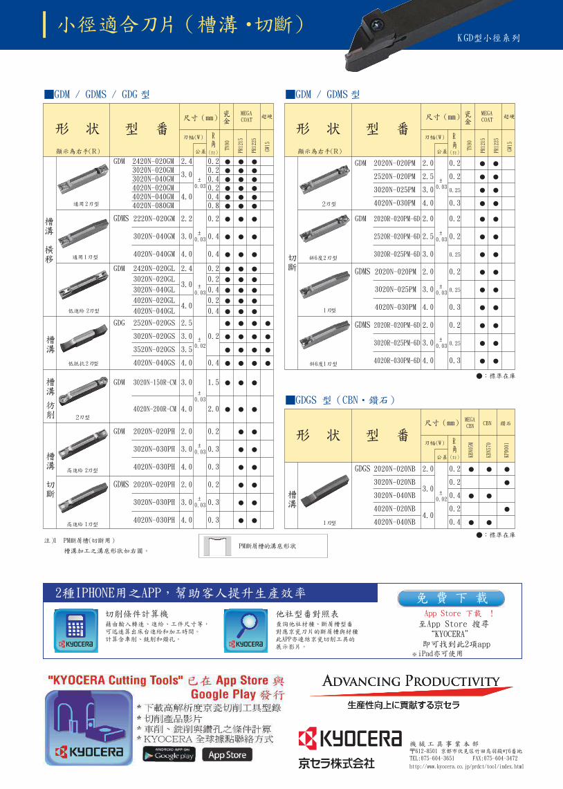
10x10mm 120mm GDM/GDMS3mm
2. 4.0mm
R/L
R/L
R/L
http://www.kyocera.co.jp/prdct/tool/index.html
2.4
3.0
4.0
0.20.20.40.20.40.8
±0.03
2420N-020GM3020N-020GM3020N-040GM4020N-020GM4020N-040GM4020N-080GM
2.2
3.0
4.0
0.2
0.4
0.4
±0.03
2220N-020GM
3020N-040GM
4020N-040GM
2.4
3.0
4.0
0.2
0.2
0.4
0.2
0.4
±0.03
2420N-020GL
3020N-020GL
3020N-040GL
4020N-020GL
4020N-040GL
2.5
3.0
3.5
4.0
0.2
0.4
±0.02
2520N-020GS
3020N-020GS
3520N-020GS
4020N-040GS
3.0
4.0
1.5
2.0
±0.03
3020N-150R-CM
4020N-200R-CM
2.0
3.0
4.0
0.2
0.3
0.3
±0.03
2020N-020PH
3020N-030PH
4020N-030PH
2.0
3.0
4.0
0.2
0.3
0.3
±0.03
2020N-020PH
3020N-030PH
4020N-030PH
GDMS
2
TN90
R
PR12
15
PR12
25
GW15
MEGACOAT
1
GDM
GDG
GDM
GDM
GDMS
GDM 2.0
2.5
3.0
4.0
0.2
0.2
0.25
0.3
±0.03
2020N-020PM
2520N-020PM
3020N-025PM
4020N-030PM
2.0
2.5
3.0
0.2
0.2
0.25
±0.03
2020R-020PM-6D
2520R-020PM-6D
3020R-025PM-6D
2.0
3.0
4.0
0.2
0.25
0.3
±0.03
2020N-020PM
3020N-025PM
4020N-030PM
2.0
3.0
4.0
0.2
0.25
0.3
±0.03
2020R-020PM-6D
3020R-025PM-6D
4020R-030PM-6D
GDM
TN90
PR12
15
PR12
25
GW15
MEGACOAT
GDMS
GDMS
2.0
3.0
4.0
0.2
0.2
0.4
0.2
0.4
±0.02
2020N-020NB
3020N-020NB
3020N-040NB
4020N-020NB
4020N-040NB
KBN0
5M
KBN5
70
KPD0
01
MEGACBN CBN
GDGS
MM
K
R
R
2
1
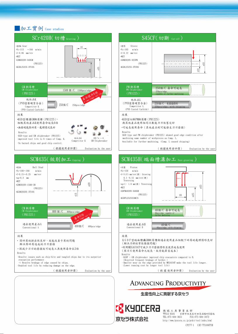
S45CF Cut-off
Sleeve
Vc=103 m/min
f=0.12 mm/rev
WET
GDM3020N-025PM
KGDL2525X-3T20S
ø33
ø10
PMPM Chipbreaker
DCompetitor L
(PVD Coated Carbide)
M
Results
·KGD-type and PM chipbreaker (PR1225) showed good edge condition after
machining same number of workpieces as Comp. L.
·Available for further machining. (Comp. L caused chipping)
Evaluation by the user
SCM435H Face grooving
Piston
Vc=150 m/min
50.0 =f mm/rev Grooving
0.1 0.15 mm/revTraversing
ap=1 1.8 mm Traversing
WET
GDFM4020N-040GM
KGDFL2525X504CS
ø25
18
ø55
GMGM Chipbreaker
Conventional B
FDGK
Results· KGDF + GM chipbreaker improved chip evacuatoin compared to B. (Resolved frequent brakage of holder.)· Smaller wear on the edge provided by MEGACOAT make the tool life longer. (Lower running cost by longer tool life)
Evaluation by the user
SCr420H Grooving
Gear
Vc=113 164 m/min
f=0.06 mm/rev
WET
GDM4020N-040GM
KGDL2525X-3T10S
10
ø35
①②③ ④
ø24
GMGM Chipbreaker
DCompetitor K
(PVD Coated Carbide)
M
Results
·KGD-type and GM chipbreaker (PR1225)
improved tool life to 6 times of Comp. K.
·No burned chips and good chip control.
Evaluation by the user
SCM435 Copying
Ball Stud
Vc=100 160 m/min
f=0.15 0.25 mm/rev
ap=0.3 mm
WET
ø13
ø20
CMCM Chipbreaker
Conventional A
Results
· Resolve issues such as chip-bite and tangled chips due to its surperior evacuation performance
=> Resolve brakage of edge caused by chips.
·Doubled tool life by reducing damage on the edge.
Evaluation by the user
Case studies
250pcs/edge, with chipping
40pcs/edge, with chipping
250pcs/edge, capable of further machining
40pcs/edge, capable of further machining
1500 1500pcs/edge
800 800pcs/edge
250pcs/edge
400pcs/edge
Competitor KGM
GM Chipbreaker
6 times
longer t
ool life
2 times
longer t
ool life
CP277-1 CAT/7T1106TYH