New ECx Outdoor - Toro · ECx Outdoor Timer Features: ... Odd/Even Watering Days ... Front Lawn -...
36
ECx Outdoor Timer Features: • Weather-Resistant Cabinet • Easily Expandable Up To 12 Zones With 2-Zone Plug-In Modules • 3 Watering Programs With: - Calendar, Interval and Odd/Even Days - 1 Min. to 4 Hrs. Valve Run Time - 4 Start Times Per Program • Battery Back-Up • Automatic Pump Start • Seasonal Run Time Adjust • Rain Delay • Rain Sensor Ready • Snap-In Wire Connectors Automatic Outdoor Sprinkler Timer User’s Guide R R
Transcript of New ECx Outdoor - Toro · ECx Outdoor Timer Features: ... Odd/Even Watering Days ... Front Lawn -...

ECx Outdoor Timer Features:• Weather-Resistant Cabinet• Easily Expandable Up To 12 Zones
With 2-Zone Plug-In Modules• 3 Watering Programs With:
- Calendar, Interval and Odd/Even Days- 1 Min. to 4 Hrs. Valve Run Time- 4 Start Times Per Program
• Battery Back-Up• Automatic Pump Start• Seasonal Run Time Adjust• Rain Delay• Rain Sensor Ready• Snap-In Wire Connectors
Automatic Outdoor Sprinkler Timer
User’s Guide
RR


ECx Introduction and Set Up
■ Timer Components .........................................2-5■ Sprinkler System Basics ....................................6■ Watering Program Basics ..................................7■ Watering Program Details ..............................8-9■ Planning Your Watering Schedule...................10■ Filling Out the Watering Schedule Form.....10-11
❚ Watering Schedule Form ..............................12■ “Remote” Programming ...................................13■ Installing the Battery ........................................13■ Selecting Optional Control Features................14
❚ 24-Hour Clock Mode .....................................14❚ 15-Second Run Delay ..................................14❚ Odd/Even Watering Days .............................14
■ About the ECx Memory....................................14■ Resetting the Timer Memory ...........................15
❚ To reset the Permanent Memory ..................15❚ To Clear the Memory ...................................15
Programming the Timer
■ Setting the Current Time and Day or Date ......16■ Setting the Watering Day Schedule............17-19
❚ Setting a Calendar Schedule ........................17❚ Setting an Interval Schedule .........................18❚ Setting an Odd/Even Schedule ....................19❚ Turning Off a Program .................................19
■ Setting Program Start Times ...........................20■ Setting Valve Run Times .................................21
Installation
■ Preparing the Cabinet for Installation ..............22■ Installing the Cabinet .......................................23■ Connecting the Valves.....................................24■ Connecting a Pump Start Relay ......................25■ Connecting a Toro Rain Switch .......................25■ Connecting the Power Source .........................26
Timer Operation
■ Automatic Operation .....................................27■ Manual Operation ..........................................28
❚ Starting Programs/Stations Manually............28❚ Watering Control Features ............................29
❚ To Pause Watering .....................................29❚ To Resume Watering..................................29❚ To Cancel Watering ....................................29❚ To Skip Zones.............................................29❚ To Adjust the Valve Run TIme....................29
■ Turning Off the ECx .........................................30■ Using the Rain Delay Feature..........................30■ Using the Season Adjust Feature ....................31
Service and Specifications
■ Replacing the Fuse..........................................32■ Adding a Zone Module.....................................32■ Troubleshooting ...............................................33■ Specifications...................................................34■ FCC Rules .......................................................34■ Warranty .........................................................34
Table of Contents
1

Timer Components
ECx Introduction and Set Up
2
PROGRAMS
B CA
RR
%
3 1
2
Timer Components
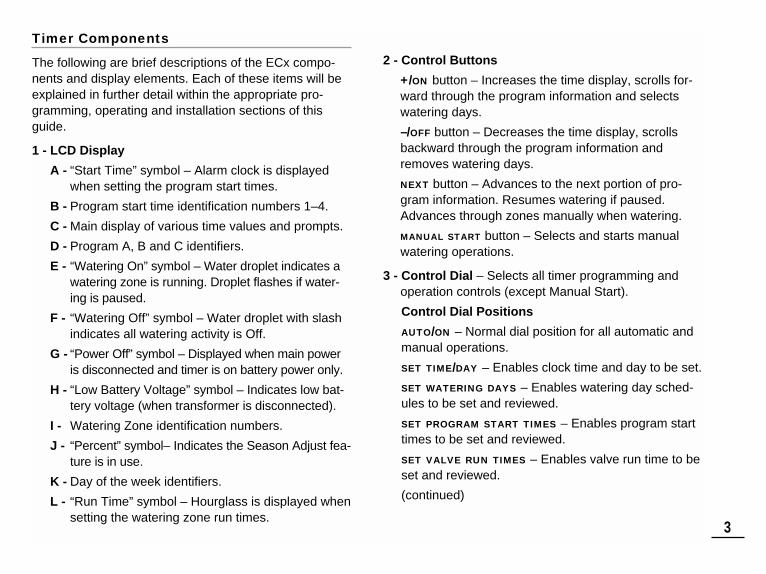
The following are brief descriptions of the ECx compo-nents and display elements. Each of these items will beexplained in further detail within the appropriate pro-gramming, operating and installation sections of thisguide.
1 - LCD Display
A - “Start Time” symbol – Alarm clock is displayedwhen setting the program start times.
B - Program start time identification numbers 1–4.
C - Main display of various time values and prompts.
D - Program A, B and C identifiers.
E - “Watering On” symbol – Water droplet indicates awatering zone is running. Droplet flashes if water-ing is paused.
F - “Watering Off” symbol – Water droplet with slashindicates all watering activity is Off.
G - “Power Off” symbol – Displayed when main poweris disconnected and timer is on battery power only.
H - “Low Battery Voltage” symbol – Indicates low bat-tery voltage (when transformer is disconnected).
I - Watering Zone identification numbers.
J - “Percent” symbol– Indicates the Season Adjust fea-ture is in use.
K - Day of the week identifiers.
L - “Run Time” symbol – Hourglass is displayed whensetting the watering zone run times.
2 - Control Buttons
+/ON button – Increases the time display, scrolls for-ward through the program information and selectswatering days.
–/OFF button – Decreases the time display, scrollsbackward through the program information andremoves watering days.
NEXT button – Advances to the next portion of pro-gram information. Resumes watering if paused.Advances through zones manually when watering.
MANUAL START button – Selects and starts manualwatering operations.
3 - Control Dial – Selects all timer programming andoperation controls (except Manual Start).
Control Dial Positions
AUTO/ON – Normal dial position for all automatic andmanual operations.
SET TIME/DAY – Enables clock time and day to be set.
SET WATERING DAYS – Enables watering day sched-ules to be set and reviewed.
SET PROGRAM START TIMES – Enables program starttimes to be set and reviewed.
SET VALVE RUN TIMES – Enables valve run time to beset and reviewed.
(continued)
3
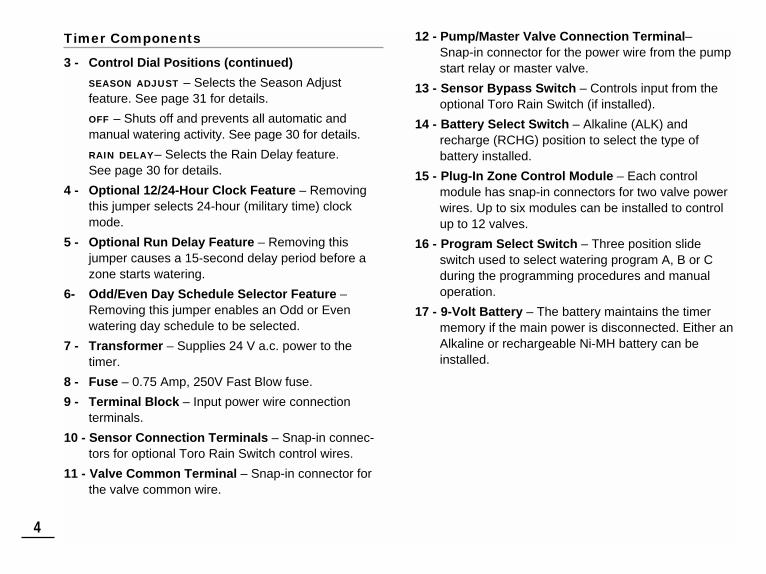
Timer Components
3 - Control Dial Positions (continued)
SEASON ADJUST – Selects the Season Adjust feature. See page 31 for details.
OFF – Shuts off and prevents all automatic and manual watering activity. See page 30 for details.
RAIN DELAY– Selects the Rain Delay feature. See page 30 for details.
4 - Optional 12/24-Hour Clock Feature – Removingthis jumper selects 24-hour (military time) clockmode.
5 - Optional Run Delay Feature – Removing thisjumper causes a 15-second delay period before azone starts watering.
6- Odd/Even Day Schedule Selector Feature –Removing this jumper enables an Odd or Even watering day schedule to be selected.
7 - Transformer – Supplies 24 V a.c. power to thetimer.
8 - Fuse – 0.75 Amp, 250V Fast Blow fuse.
9 - Terminal Block – Input power wire connection terminals.
10 - Sensor Connection Terminals – Snap-in connec-tors for optional Toro Rain Switch control wires.
11 - Valve Common Terminal – Snap-in connector forthe valve common wire.
12 - Pump/Master Valve Connection Terminal– Snap-in connector for the power wire from the pumpstart relay or master valve.
13 - Sensor Bypass Switch – Controls input from theoptional Toro Rain Switch (if installed).
14 - Battery Select Switch – Alkaline (ALK) andrecharge (RCHG) position to select the type of battery installed.
15 - Plug-In Zone Control Module – Each control module has snap-in connectors for two valve powerwires. Up to six modules can be installed to controlup to 12 valves.
16 - Program Select Switch – Three position slideswitch used to select watering program A, B or Cduring the programming procedures and manualoperation.
17 - 9-Volt Battery – The battery maintains the timermemory if the main power is disconnected. Either anAlkaline or rechargeable Ni-MH battery can beinstalled.
4
5
BATTERY
MANUALSTART
ON
NEXT
OFF
PROGRAMS
B CA
Timer Components
3
4
5
7
8
9
10
11 12 13 14 15 16 17
6

The three main components of every automatic sprin-kler system are the timer, zone control valves andsprinklers.
The timer is the brain of the system, telling the controlvalves when and how long to supply water to the sprin-klers. The sprinklers direct and control the water appliedto the lawn and plants.
Each valve controls a specific group of sprinklers calleda watering zone. The zones are generally laid out andinstalled according to the type of plant material to bewatered, the location of the plant within the landscapeand the maximum amount of water which can be sup-plied. Each valve is connected to a numbered terminalwithin the timer, identifying it as zone 1, zone 2, etc.
The timer operates the zones in order, one at a time. In other words, one zone would water completelybefore another zone would turn on. This is called awatering cycle. The information stored in the timermemory which determines when and how long thezones will water is called a program.
The next section of this guide is very important. Itexplains what a program is and how the ECx controlsthe operation of the sprinkler system.
Sprinkler System Basics
6
MANUALSTART
ON
NEXT
OFF
PROGRAMS
B CA
RR
Valve 1 - Zone 1 - Parkway Lawn - Fixed Spray
Valve 2 - Zone 2 - Front Lawn - Fixed Spray
Valve 3 - Zone 3 - Front Shrubs - Flood Bubbler
Valve 4 - Zone 4 - Back Lawn - Geared Rotor
Valve 5 - Zone 5 - Garden - Drip
Valve 1
ECx Timer
Valve 2
House
Valve 3
Valve 4
Valve 5

A watering program requires three basic instructions tooperate automatically:• What days to water –called watering days• When to water – called a program start time• How long to water – called valve run time
The following example illustrates how a typical wateringprogram could be set for the sprinkler system shown onthe previous page.
Example: The program start time is set for 5:00 AM. Lawnzones 1 and 2 each have a run time of 10 minutes andlawn zone 4 is set to run for 20 minutes. Note that zones3 and 5 water shrubs and flowers and have been exclud-ed from this program. (These zones will be set to oper-ate on separate programs).
As shown in the watering program diagram, at 5:00 AM
the timer starts the program watering cycle. Zone 1sprinklers run for 10 minutes and shut off. Zone 2 sprin-klers turn on, run for 10 minutes and shut off. The timerskips zone 3 and turns on zone 4, which runs for 20 min-utes and shuts off. Zone 5 is skipped and the wateringcycle ends at 5:40 AM.
As you can see from this example, only one programstart time was needed to operate three different zones.
Because of variations in plant watering needs, the ECxprovides three separate programs. The programs, calledA, B and C, are completely independent of one another– like having three timers in one housing.
Using more than one program for example, would enablelawn zones to be watered every day on program A,shrub zones to run on on Monday, Wednesday and Fri-day on program B, and drip irrigation to soak the flowerbeds every three days on program C.
Although the ECx offers the multiple program feature,you may want to have all zones on one program if itmeets your needs. The other programs can remainturned off until you need to use them.
Watering Program Basics
7
3
12
9
6
3
12
9
6
3
12
9
6
Zone 1
Program Starts - 5:00 AM
ProgramEnds- 5:40 AM
Zone 2
Zone 4
Watering Program Diagram
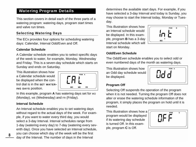
This section covers in detail each of the three parts of awatering program: watering days, program start timesand valve run times.
Selecting Watering Days
The ECx provides four options for scheduling wateringdays: Calendar, Interval Odd/Even and Off.
Calendar Schedule
A Calendar schedule enables you to select specific daysof the week to water, for example, Monday, Wednesdayand Friday. This is a seven-day schedule which starts onSunday and ends on Saturday.
This illustration shows howa Calendar schedule wouldbe displayed when the con-trol dial is in the SET WATER-ING DAYS position.
In this example, program A has watering days set for MO
(Monday), WE (Wednesday) and FR (Friday).
Interval Schedule
An Interval schedule enables you to set watering dayswithout regard to the actual days of the week. For exam-ple, if you want to water every third day, you wouldselect a 3-day Interval. Interval schedules range from 1-day (watering every day) to 7-day (watering every sev-enth day). Once you have selected an Interval schedule,you can choose which day of the week will be the firstday of the Interval. The number of days in the Interval
determines the available start days. For example, if youhave selected a 3-day Interval and today is Sunday, youmay choose to start the Interval today, Monday or Tues-day.
This illustration shows howan Interval schedule wouldbe displayed. In this exam-ple, program B has a 3-dayInterval schedule which willstart on Monday.
Odd/Even Schedule
The Odd/Even schedule enables you to select odd oreven numbered days of the month as watering days.
This illustration shows howan Odd day schedule wouldbe displayed.
Program Off
Selecting Off suspends the operation of the programwhen it is not needed. Turning the program Off does notalter or erase the watering schedule information of theprogram, it simply places the program on hold until it isneeded.
This illustration shows how aprogram would be displayedif its watering day scheduleis turned Off. In this exam-ple, program C is Off.
Watering Program Details
8
PGM A
SU MO TU WE TH FR SA
PGM A B C
SU MO TU WE TH FR SA1 2 3 4 5 6 7 8
PGM A

Selecting Program Start Times
A program start time is the time of day you select tobegin an automatic program watering cycle. It is important to remember that a program onlyrequires one start time to operate automatically.When a program starts, each zone assigned to the pro-gram will water in numerical order, one at a time for itsset run time.
Sometimes it is necessary to run a watering programmore than one time per day. For example, when growinga new lawn. The ECx enables each program to have upto four separate start times per day.
Program start times are numbered 1 through 4. Thesenumbers are shown at the top of the display next to thestart time symbol when the control dial is in theSET PROGRAM START TIMES position and indicate howmany start times are currently set for the program.
This illustration shows howa program start time is displayed. In this example,program A has one starttime (start time number 1)set for 5:00 AM.
Setting the Valve Run Time
A valve run time is the length of time the zone (controlledby the valve) will water during the program wateringcycle. The run time for each valve can be set from Off(no run time) to 4 hours, in one-minute increments.
A zone is assigned to a program when it is given a valverun time. If the run time for a valve is turned Off in a pro-gram, it will not operate during the program wateringcycle. This is how the ECx enables you to assign water-ing zones to different programs.
All zones assigned to the program are shown on thelower portion of the display when the control dial is in the SET VALVE RUN TIMES position.
This illustration shows how a valve run time is displayedfor a program. In this exam-ple, zones 1–6 are assignedto program A. Zone 1 has a10-minute valve run timeand the valve for zone 2 isset to run for 25 minutes.
The valve run time being displayed is identified by theflashing zone number.
9
Flashing
Flashing
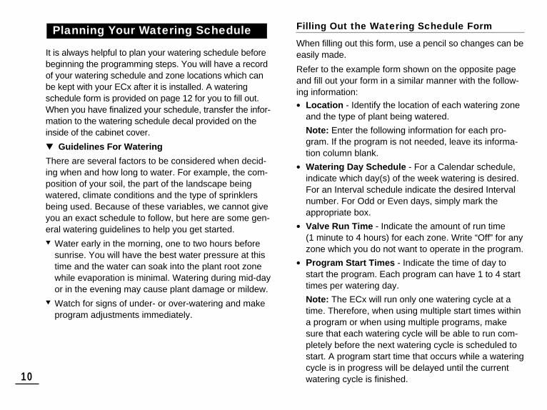
It is always helpful to plan your watering schedule beforebeginning the programming steps. You will have a recordof your watering schedule and zone locations which canbe kept with your ECx after it is installed. A wateringschedule form is provided on page 12 for you to fill out.When you have finalized your schedule, transfer the infor-mation to the watering schedule decal provided on theinside of the cabinet cover.
▼ Guidelines For Watering
There are several factors to be considered when decid-ing when and how long to water. For example, the com-position of your soil, the part of the landscape beingwatered, climate conditions and the type of sprinklersbeing used. Because of these variables, we cannot giveyou an exact schedule to follow, but here are some gen-eral watering guidelines to help you get started.▼ Water early in the morning, one to two hours before
sunrise. You will have the best water pressure at thistime and the water can soak into the plant root zonewhile evaporation is minimal. Watering during mid-dayor in the evening may cause plant damage or mildew.
▼ Watch for signs of under- or over-watering and makeprogram adjustments immediately.
Filling Out the Watering Schedule Form
When filling out this form, use a pencil so changes can beeasily made.
Refer to the example form shown on the opposite pageand fill out your form in a similar manner with the follow-ing information:
• Location - Identify the location of each watering zoneand the type of plant being watered.
Note: Enter the following information for each pro-gram. If the program is not needed, leave its informa-tion column blank.
• Watering Day Schedule - For a Calendar schedule,indicate which day(s) of the week watering is desired.For an Interval schedule indicate the desired Intervalnumber. For Odd or Even days, simply mark theappropriate box.
• Valve Run Time - Indicate the amount of run time (1 minute to 4 hours) for each zone. Write “Off” for anyzone which you do not want to operate in the program.
• Program Start Times - Indicate the time of day tostart the program. Each program can have 1 to 4 starttimes per watering day.
Note: The ECx will run only one watering cycle at atime. Therefore, when using multiple start times withina program or when using multiple programs, makesure that each watering cycle will be able to run com-pletely before the next watering cycle is scheduled tostart. A program start time that occurs while a wateringcycle is in progress will be delayed until the currentwatering cycle is finished.
Planning Your Watering Schedule
10
11
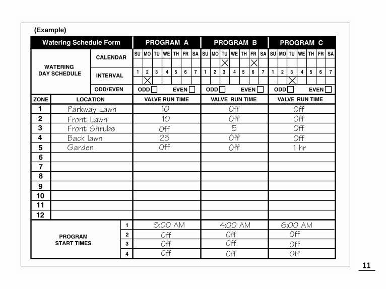
(Example)

12
The ECx timer features the ability to be fully programmedbefore installation. Installing its 9-volt battery brings theECx to life, so you can program your new timer while inthe comfort of your home.
The ECx can use either type of 9-volt battery: Alkaline orrechargeable Nickel Metal Hydride (Ni-MH). The Alkalinebattery provided will keep the timer’s clock and program-mable memory functioning for about 72 hours and shouldbe replaced every year. A fully-charged Ni-MH battery willlast about 24 hours, but is continuously recharged to pro-vide service for many years.
If your home has frequent power interruptions, installing arechargeable Ni-MH battery is recommended.
Note: The battery does not supply power to operate thezone control valves; power from the transformer must besupplied.
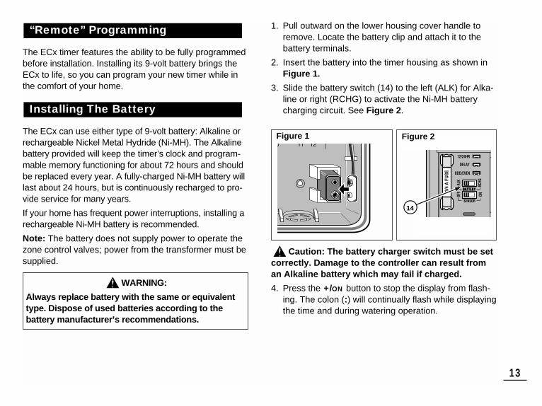
1. Pull outward on the lower housing cover handle toremove. Locate the battery clip and attach it to thebattery terminals.
2. Insert the battery into the timer housing as shown inFigure 1.
3. Slide the battery switch (14) to the left (ALK) for Alka-line or right (RCHG) to activate the Ni-MH batterycharging circuit. See Figure 2.
Caution: The battery charger switch must be setcorrectly. Damage to the controller can result froman Alkaline battery which may fail if charged.
4. Press the +/ON button to stop the display from flash-ing. The colon (:) will continually flash while displayingthe time and during watering operation.
Installing The Battery
“Remote” Programming
13
BATTERY
Figure 1 Figure 2
14
WARNING:
Always replace battery with the same or equivalenttype. Dispose of used batteries according to the battery manufacturer’s recommendations.

24-Hour Clock Mode
The ECx is set to displaytime in the 12-hour clockmode. If you prefer to use a 24-hour clock mode (military time), select thisoption by removing the12/24 Hour SelectorJumper (4). To store thejumper, install it on one pinas shown. See Figure 3.
15-Second Run Delay
The 15-second run delay feature is useful for sprinklersystems utilizing a pump or master valve. For example, a pump usually requires a few seconds to build pressureafter first starting. With the 15-second run delay selected,the pump would be running (or the master valve wouldopen) 15 seconds before the first zone begins watering.A 15-second delay would also occur between zone oper-ations. This helps ensure that one valve is closed beforeanother valve opens. Note: A 2-second run delay will occur if this option is notselected.To select the 15-second delay option, remove the DelaySelector Jumper (5).
Odd/Even Watering Days
If you plan to use an Odd or Even day watering schedule,remove the Odd/Even Selector Jumper (6) for this option.
The ECx has a permanent watering schedule within itsmemory to assist you in two ways. First, it will restorewatering operation in case your watering program is lostdue to a power interruption lasting longer than the bat-tery life. This prevents your landscape from going unwa-tered if the power outage occurs while you are away.
Secondly, if you do not want to program your ECx,you may use the permanent watering schedule tooperate your sprinklers. Just set the current timeand day and your ECx will be ready to operate auto-matically.
The permanent watering schedule operates as follows:When power is applied, the timer clock is set to 12:00 AM
Sunday. Program A has a Calendar watering scheduleset to water every day. One program start time is set for5:00 AM and a run time of 10 minutes is set for eachzone. Programs B and C are turned Off and have noprogram start times or run times.
Note: An optional feature is provided which enables theThe ECx memory to be reset to the permanent programor cleared completely if you choose. If you do not want touse this option, skip the next procedure “Resetting TheTimer Memory” and continue at page 16 to begin pro-gramming.
About the ECx MemorySelecting Optional Features
14
BATTERY
4
5
6
Figure 3

15
The ECx program memory can be reset to the perma-nent program values or cleared completely at any timewithout removing power.
Resetting the permanent program erases all user inputand replaces it with the permanent program values.
Clearing the program memory sets all program values toOff (i.e., no active days, program start times or zone runtimes). You may find that this simplifies programming thetimer if your watering requirements are quite differentthan the permanent values.
Note: When power is first applied, the ECx will alwaysreset to the permanent program values.
To Reset the Permanent Program (Figure 4)
Turn the control dial to the OFF position. OFF will bedisplayed.
Press the +/ON and –/OFF buttons at the same timeuntil CLR is displayed.
Return the control dial to the AUTO/ON position.
To Clear the Memory (Figure 5)
Turn the control dial to the OFF position. OFF will bedisplayed.
Press the +/ON and NEXT buttons at the same timeuntil CLR 0 is displayed.
Return the control dial to the AUTO/ON position.
Resetting the Timer Memory
2
2
1
3
MANUALSTART
AUTO / ON
SET TIME / DAY
SET VALVERUN TIMES
SEASONADJUST
OFF
RAIN DELAY
SETWATERING DAYS
SETPROGRAMSTART TIMES
ON
NEXT
OFF
PROGRAMS
2
1
3
MANUALSTART
AUTO / ON
SET TIME / DAY
SET VALVERUN TIMES
SEASONADJUST
OFF
RAIN DELAY
SETWATERING DAYS
SETPROGRAMSTART TIMES
ON
NEXT
OFF
2
PROGRAMS
Figure 4
Figure 5
16
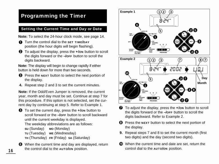
Note: To select the 24-hour clock mode, see page 14.
Turn the control dial to the SET TIME/DAY
position (the hour digits will begin flashing).
To adjust the display, press the +/ON button to scrollthe digits forward or the –/OFF button to scroll thedigits backward.
Note: The display will begin to change rapidly if either button is held down for more than two seconds.
Press the NEXT button to select the next portion ofthe display.
4. Repeat step 2 and 3 to set the current minutes.
Note: If the Odd/Even Jumper is removed, the currentyear, month and day must be set. Continue at step 7 forthis procedure. If this option is not selected, set the cur-rent day by continuing at step 5. Refer to Example 1.
To set the current day, press the +/ON button toscroll forward or the –/OFF button to scroll backwarduntil the current weekday is displayed.The weekday abbreviations are as follows:SU (Sunday) MO (Monday) TU (Tuesday) WE (Wednesday) TH (Thursday) FR (Friday) SA (Saturday)
When the current time and day are displayed, returnthe control dial to the AUTO/ON position.
To adjust the display, press the +/ON button to scrollthe digits forward or the –/OFF button to scroll thedigits backward. Refer to Example 2.
Press the NEXT button to select the next portion ofthe display.
9. Repeat steps 7 and 8 to set the current month (firsttwo digits) and the day (second two digits).
When the current time and date are set, return thecontrol dial to the AUTO/ON position.
Setting the Current Time and Day or Date
Programming the TimerAM
6
13
2 5
2 5
3
MANUALSTART
AUTO / ON
SET TIME / DAY
SET VALVERUN TIMES
SEASONADJUST
OFF
RAIN DELAY
SETWATERING DAYS
SETPROGRAMSTART TIMES
ON
NEXT
OFF
PROGRAMS
1 2
5
SU
AM
10
13 8
2 7
2 7
3
MANUALSTART
AUTO / ON
SET TIME / DAY
SET VALVERUN TIMES
SEASONADJUST
OFF
RAIN DELAY
SETWATERING DAYS
SETPROGRAMSTART TIMES
ON
NEXT
OFF
PROGRAMS
1 2
5
SU
7 8 7
Example 1
Example 2
Day
Month

For each program, you can select Calendar, IntervalOdd/Even or Off. To set a Calendar schedule, continuehere. To set an Interval schedule see page 18. To set aOdd or Even day schedule or to turn Off a program, seepage 19.
Setting a Calendar Schedule
Turn the control dial to the SET WATERING DAYS
position.
Check the PROGRAMS switch setting. If necessary,reposition the switch to select the desired program.
The current watering schedule will be displayed. IfCAL (Calendar) is not displayed, press the +/ON or–/OFF button as needed to select CAL.
Press the NEXT button. The watering days currentlyset for this program will be displayed. SU (Sunday)will begin flashing.
To select Sunday as a watering day, press the +/ON
button. To remove Sunday from the schedule, pressthe –/OFF button. MO (Monday) will now begin flash-ing. Continue to select or remove each day of theweek until only the desired watering days are shown.
6. To set a Calendar schedule for another program,repeat all of the steps beginning at step .
When you have completed setting the Calendarschedule for each program (as needed) return thecontrol dial to the AUTO/ON position.
Note: Each program can have its own Calendar, Intervalor Odd/Even schedule, but only one schedule can beactive at a time for that program. The watering dayschedule or OFF shown in the display when the controldial is in the SET WATERING DAYS position, will be thecurrent schedule for that program.
Setting the Watering Day Schedule
17
4
3
1
PGM A
32
7
5
5
54
2
SU MO TU WE TH FR SA
3
MANUALSTART
AUTO / ON
SET TIME / DAY
SET VALVERUN TIMES
SEASONADJUST
OFF
RAIN DELAY
SETWATERING DAYS
SETPROGRAMSTART TIMES
ON
NEXT
OFF
PROGRAMS
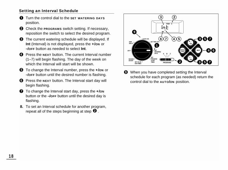
Setting an Interval Schedule
Turn the control dial to the SET WATERING DAYS
position.
Check the PROGRAMS switch setting. If necessary,reposition the switch to select the desired program.
The current watering schedule will be displayed. IfInt (Interval) is not displayed, press the +/ON or–/OFF button as needed to select Int.
Press the NEXT button. The current Interval number(1–7) will begin flashing. The day of the week onwhich the Interval will start will be shown.
To change the Interval number, press the +/ON or–/OFF button until the desired number is flashing.
Press the NEXT button. The Interval start day willbegin flashing.
To change the Interval start day, press the +/ON
button or the –/OFF button until the desired day isflashing.
8. To set an Interval schedule for another program,repeat all of the steps beginning at step .
When you have completed setting the Intervalschedule for each program (as needed) return thecontrol dial to the AUTO/ON position.
18
9
5 7
4 6
3
5 73
2
PGM A
3
57 4
1
3 2
MO
6
MANUALSTART
AUTO / ON
SET TIME / DAY
SET VALVERUN TIMES
SEASONADJUST
OFF
RAIN DELAY
SETWATERING DAYS
SETPROGRAMSTART TIMES
ON
NEXT
OFF
PROGRAMS

Setting an Odd or Even Schedule
Note:The Odd/Even Selector Jumper must be removedfor this type of watering schedule. See page 14 for details.
Turn the control dial to the SET WATERING DAYS
position.
Check the PROGRAMS switch setting. If necessary,reposition the switch to select the desired program.
The current watering schedule will be displayed. IfOdd or Even is not displayed, press the +/ON or–/OFF button as needed to select Odd or Even.
Note: When Odd is selected, the 31st day of the monthand the 29th day of a leap year will not be active water-ing days.
4. To set an Odd or Even schedule for another program, repeat steps and as needed.
When you have completed setting the Odd or Evenschedule for each program as needed, return thecontrol dial to the AUTO/ON position.
Turning Off a Program
Note: Turning off a program does not alter or erase apreset watering day schedule. Selecting Off simplyplaces the program on hold until one of the watering dayschedules is selected.
Turn the control dial to the SET WATERING DAYS
position.
Check the PROGRAMs switch setting. If necessary,reposition the switch to select the desired program.
Press the +/ON or –/OFF button until OFF is flashing.
4. To turn another program Off, repeat steps andas needed.
Return the control dial to the AUTO/ON position.
19
3
3
1
5
2
3 2
PGM B
MANUALSTART
AUTO / ON
SET TIME / DAY
SET VALVERUN TIMES
SEASONADJUST
OFF
RAIN DELAY
SETWATERING DAYS
SETPROGRAMSTART TIMES
ON
NEXT
OFF
PROGRAMS
PGM B
5
1
2
3
3
2
MANUALSTART
AUTO / ON
SET TIME / DAY
SET VALVERUN TIMES
SEASONADJUST
OFF
RAIN DELAY
SETWATERING DAYS
SETPROGRAMSTART TIMES
ON
NEXT
OFF
PROGRAMS
3
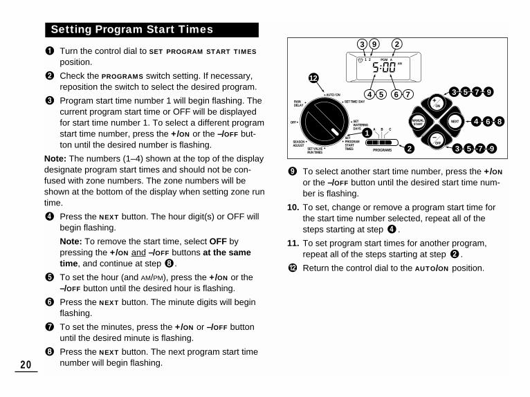
Turn the control dial to SET PROGRAM START TIMES
position.
Check the PROGRAMS switch setting. If necessary,reposition the switch to select the desired program.
Program start time number 1 will begin flashing. Thecurrent program start time or OFF will be displayedfor start time number 1. To select a different programstart time number, press the +/ON or the –/OFF but-ton until the desired number is flashing.
Note: The numbers (1–4) shown at the top of the displaydesignate program start times and should not be con-fused with zone numbers. The zone numbers will beshown at the bottom of the display when setting zone runtime.
Press the NEXT button. The hour digit(s) or OFF willbegin flashing.
Note: To remove the start time, select OFF bypressing the +/ON and –/OFF buttons at the sametime, and continue at step .
To set the hour (and AM/PM), press the +/ON or the–/OFF button until the desired hour is flashing.
Press the NEXT button. The minute digits will beginflashing.
To set the minutes, press the +/ON or –/OFF buttonuntil the desired minute is flashing.
Press the NEXT button. The next program start timenumber will begin flashing.
To select another start time number, press the +/ON
or the –/OFF button until the desired start time num-ber is flashing.
10. To set, change or remove a program start time forthe start time number selected, repeat all of thesteps starting at step .
11. To set program start times for another program,repeat all of the steps starting at step .
Return the control dial to the AUTO/ON position.
Setting Program Start Times
20
PGM AAM
1 2
12
1
4 6 8
3 5 7
3
4 5 6 7
75
9 23
9
92
MANUALSTART
AUTO / ON
SET TIME / DAY
SET VALVERUN TIMES
SEASONADJUST
OFF
RAIN DELAY
SETWATERING DAYS
SETPROGRAMSTART TIMES
ON
NEXT
OFF
PROGRAMS

Turn the control dial to the SET VALVE RUN TIMES
position.
Check the PROGRAMS switch setting. If necessary,reposition the switch to select the desired program.
Zone number 1 will be flashing and its current runtime or OFF will be shown. To select a different zonenumber, press the +/ON or the –/OFF button until thedesired zone number is flashing.
Press the NEXT button. The run time (or OFF) willbegin flashing.
To set the run time, press the +/ON or the –/OFF but-ton until the desired run time is shown.
Note: To remove the run time, select OFF by pressingthe +/ON and –/OFF buttons at the same time.
Press the NEXT button. The next zone number willbegin flashing.
7. Repeat steps and as needed to set, change,or remove the run time for the remaining zones.
8. To set the zone run time for another program, repeatall of the steps starting at step .
Return the control dial to the AUTO/ON position.
Setting Valve Run Times
21
PGM A
1 2 3 4 5 6
3 5
3 5
6
9
4
3
5
21
42
MANUALSTART
AUTO / ON
SET TIME / DAY
SET VALVERUN TIMES
SEASONADJUST
OFF
RAIN DELAY
SETWATERING DAYS
SETPROGRAMSTART TIMES
ON
NEXT
OFF
PROGRAMS
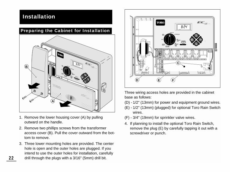
1. Remove the lower housing cover (A) by pulling outward on the handle.
2. Remove two phillips screws from the transformeraccess cover (B). Pull the cover outward from the bot-tom to remove.
3. Three lower mounting holes are provided. The centerhole is open and the outer holes are plugged. If youintend to use the outer holes for installation, carefullydrill through the plugs with a 3/16" (5mm) drill bit.
Three wiring access holes are provided in the cabinetbase as follows: (D) - 1/2" (13mm) for power and equipment ground wires.(E) - 1/2" (13mm) (plugged) for optional Toro Rain Switch
wires.(F) - 3/4" (19mm) for sprinkler valve wires.
4. If planning to install the optional Toro Rain Switch,remove the plug (E) by carefully tapping it out with ascrewdriver or punch.
Installation
22
Preparing the Cabinet for Installation
MANUALSTART
ON
NEXT
OFF
VALVE
RRRR
®
BATTERY
MANUALSTART
ON
NEXT
OFF
PROGRAMS
B CA
®
B
A
C
D E F

1. For safe, reliable operation, select an installation sitewhich will provide the following conditions:• Protection from irrigation spray, exposure to direct
sun during the hottest hours, wind and snow.• Access to a grounded power source which is not
controlled by a light switch or utilized by a high current load appliance, such as a refrigerator or airconditioner.
• Access to the sprinkler control valve wiring andoptional accessory wiring.
2. Drive a wood screw (provided) into the wall at eyelevel (A). Leave the screw extended approximately1/4" (6.5mm) from the wall.
Note: If you are installing the timer cabinet on drywallor masonry, install screw anchors to prevent screwsfrom loosening. Use the dimension shown to predrillholes for screw anchors.
3. Hang the cabinet on the screw using the keyhole slot (B) on the back panel. Make sure the cabinetslides down securely on the screw.
4. Install the lower mounting screw(s) and tightensecurely.
Note: Conduit and adapters are not provided. Installconduit as required by local electrical codes.
5. Install 1/2" (13mm) conduit (C) for power/equipmentground wires and 3/4" (19mm) conduit (D) for valvewires.
Note: After installation, store the User’s Guide andQuick Reference Guide on the hook located on theinside of the door.
Installing the Cabinet
23
BATTERY
MANUALSTART
ON
NEXT
OFF
PROGRAMS
B CA
VALVE
®
B
C D
6"(15.2cm)
A

1. Route the valve control wires between the valves andthe timer.
Note: Using 18 AWG (1.0mm2) multi-wire sprinklervalve connection cable is recommended. This cable is insulated for direct burial and is color-coded to simplify installation.
2. Attach the white color-coded wire from the cable toone wire from each valve solenoid. (Either solenoidwire can be used for this connection.) This is calledthe valve common wire.
3. Attach a separate cable wire to the remaining wirefrom each valve solenoid. Make a note of the wirecolor code used for each valve and the watering zoneit controls. You will need to have this informationwhen connecting the valve wires to the timer.
4. Use screw-on wire fasteners to secure each wire con-nection. Waterproof all connections with grease capsor simular insulation method.
5. Route the wire cable into the timer. Strip insulationback 1/2" (13mm) from all cable wires.
Note: The ECx has snap-in wire terminals. To attachwires, simply raise the lever, insert the stripped wire,and press the lever down to secure.
6. Referring to the Timer Components on page 5 and the diagram above, secure the valve common wire tothe terminal labeled COM (11). Connect the individualzone valve wires to the appropriate zone module terminals (15). Connect the master valve wire (ifapplicable) to the terminal labeled PUMP/MV (12).
Note: Connecting a master valve (or pump relay) isoptional and may not be required in your sprinklersystem.
Connecting the Valves
24
BATTERY
START
OFF
PROGRAMS
B CA
Valve CommonWire
ZoneValves
MasterValve
15
11
12

(Optional)
Caution: To prevent timer damage, ensure therelay current draw does not exceed 0.30 Amps.Do not connect the timer directly to the pumpstarter.
1. Route a wire pair from the 24 Va.c. pump relay intothe timer housing.
2. Connect one wire to the terminal labeled COM (11).Connect the remaining wire to the terminal labeledPUMP/MV (12) as shown below.
Caution: To prevent pump damage due to“Dead-heading,” connect a jumper wire fromany unused zone terminal to a zone terminalwith a valve connected.
(Optional)
The Toro Rain Switch (model # 53221) is a remote rainsensing device which can be connected directly to yourECx timer to automatically interrupt watering during rain.
A Sensor bypass switch is provided to enable the RainSwitch operation to beturned On and Off.
When the Rain Switchabsorbs rain water it auto-matically signals the ECx tosuspend all watering opera-tions. The “No Watering”symbol will appear in theupper right corner of the display until the Rain Switchdrys out and automaticallyresets. The “No Watering” symbol will disappear andtimer operation will resume as programmed. 1. Route the wire cable from Toro Rain Switch into the
timer housing through the access hole provided.2. The Rain Switch cable has four wires: two copper
wires and two silver wires. Only two of the wires areused. Connect the heavier 18 AWG (1.0mm2) copperwire and the thin 24 AWG (0.50mm2) silver wire to theterminals labeled SENSOR (10). Trim off the remain-ing two cable wires.
3. Set Sensor Switch (13) as required: ON allows theRain Switch to interrupt watering; OFF bypasses theRain Switch input.
Connecting a Toro Rain SwitchConnecting a Pump Start Relay
25
BATTERY
24 V a.c. Pump Relay Valve Common Wire
Jumper Wire
Toro Rain Switch
11
10
13
12

1. Route the power and equipment ground wires from thepower source, through the conduit and into the con-troller transformer compartment.
Note: The controller terminal block accepts wire sizeup to 12 AWG (4mm2).
2. Remove 3/8" (10mm) insulation from the wire ends.
3. Using a small flat blade screwdriver, secure the wiresas shown to the terminal block positions as follows:Line to L, Neutral to N and Equipment Ground to .
Note: The bottom terminal is not used.
4. Install and secure the transformer compartmentcover.
5. Apply power to the controller.
Connecting the Power Source
26
WARNING:AC power wiring must be installed and connectedby qualified personnel only. All electrical compo-nents and installation procedures must complywith all applicable local and national electricalcodes. Some codes may require a means of discon-nection from the AC power source installed in thefixed wiring and having a contact separation of atleast 0.120" (3mm) in the line and neutral poles.
Make sure the power source is OFF prior to con-necting the controller.
BATTERY

The ECx timer has three modes of operation: Automatic,Manual and Off. In the Automatic mode the timer tracksthe time and day and operates the automatic wateringschedules. The Manual mode enables the watering pro-grams to be started and controlled manually at any time.The Off mode shuts off all watering activity and preventsany zones from operating automatically or manually.
The Rain Delay and Season Adjust control features areprovided to enable quick, temporary changes in operationto help compensate for variables in weather and season.
Each of the operating modes and control features areexplained in this section of the guide and can be foundon the following pages:
• Automatic Operation, page 27• Manual Operation, page 28• Watering Control Features, page 29• Turning Off The ECx, page 30• Using the Rain Delay Feature, page 30• Using the Season Adjust Feature, page 31
In the Automatic mode, the ECx keeps track of the cur-rent time, day of the week and the automatic wateringprogram schedule. Automatic operation will occur when-ever a programmed watering day and start time matchthe current time and day.
The Automatic mode is selected when the control dial isin the AUTO/ON position. While in the automatic mode,the display will show two types of information: status andoperation.
This illustration shows thestatus display. In thisexample the current time is2:45 PM and the currentday is Monday. ProgramsA and B are active on Monday.
When watering starts, the operating display appears andis shown for the duration of the program.
In this example, program Ais operating. Zone 1 iswatering and has 10 min-utes of run time remaining.Zones 2, 3 and 4 will oper-ate during this program.
Note: If the control dial remains in any other position(except OFF) for more than 8 minutes, the timer reverts tothe Automatic mode.
Note: The position of the PROGRAMS switch does notdetermine which program will run during automatic con-troller operation. In other words, if a program has anassigned watering day schedule, start time and a zonewith run time, it will operate automatically regardless ofthe position of the PROGRAMS switch.
Automatic Operation
Timer Operation
27
PM
MO
Flashing
Flashing

Manual operation enables the automatic watering pro-grams or selected zones assigned to the program to bestarted manually. During operation, temporary changescan be made to increase or decrease the valve run time,step through the valve sequence and pause or stopwatering using the “Watering Control Features”described on page 29. Upon completion of the manualwatering operation, the controller will return to the Auto-matic mode.
Starting Programs and/or Zones ManuallyYou may choose to operate all zones or selected zonesin each program. Watering programs can be started individually or set to start in order. When one programfinishes the next selected program will operate.
Ensure the control dial is in the AUTO/ON position.
Position the PROGRAMS switch to select the programyou wish to start.
Choose one of the following manual operations:
• To operate the selected program with allassigned zones, press the MANUAL START
button two times to begin watering.
• To operate only selected zones, press the MANUAL START button, then press the +/ON buttonto select the flashing zone number, or press the–/OFF button to skip the zone number. Continueselecting or omitting zones in this manner. Whenonly the desired zones are displayed, press theMANUAL START button again to begin watering.
4. To select additional programs, repeat steps and .
Note: Additional programs set to start will operateone at a time in alphabetical order. Each programletter will be displayed as it is selected. The programcurrently operating is indicated by the flashing pro-gram letter.
Manual Operation
28
Flashing
Flashing
Example: Program A is operating. Program B will startwhen program A is finished.
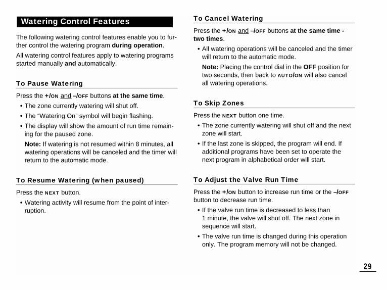
The following watering control features enable you to fur-ther control the watering program during operation.
All watering control features apply to watering programsstarted manually and automatically.
To Pause Watering
Press the +/ON and –/OFF buttons at the same time.
• The zone currently watering will shut off.
• The “Watering On” symbol will begin flashing.
• The display will show the amount of run time remain-ing for the paused zone.
Note: If watering is not resumed within 8 minutes, allwatering operations will be canceled and the timer willreturn to the automatic mode.
To Resume Watering (when paused)
Press the NEXT button.
• Watering activity will resume from the point of inter-ruption.
To Cancel Watering
Press the +/ON and –/OFF buttons at the same time -two times.
• All watering operations will be canceled and the timerwill return to the automatic mode.
Note: Placing the control dial in the OFF position fortwo seconds, then back to AUTO/ON will also cancelall watering operations.
To Skip Zones
Press the NEXT button one time.
• The zone currently watering will shut off and the nextzone will start.
• If the last zone is skipped, the program will end. Ifadditional programs have been set to operate thenext program in alphabetical order will start.
To Adjust the Valve Run Time
Press the +/ON button to increase run time or the –/OFF
button to decrease run time.
• If the valve run time is decreased to less than 1 minute, the valve will shut off. The next zone insequence will start.
• The valve run time is changed during this operationonly. The program memory will not be changed.
Watering Control Features
29
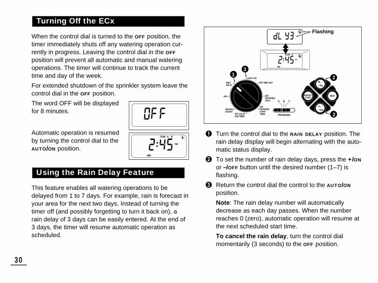
When the control dial is turned to the OFF position, thetimer immediately shuts off any watering operation cur-rently in progress. Leaving the control dial in the OFF
position will prevent all automatic and manual wateringoperations. The timer will continue to track the currenttime and day of the week.
For extended shutdown of the sprinkler system leave thecontrol dial in the OFF position.
The word OFF will be displayed for 8 minutes.
Automatic operation is resumedby turning the control dial to theAUTO/ON position.
This feature enables all watering operations to bedelayed from 1 to 7 days. For example, rain is forecast inyour area for the next two days. Instead of turning thetimer off (and possibly forgetting to turn it back on), arain delay of 3 days can be easily entered. At the end of3 days, the timer will resume automatic operation asscheduled.
Turn the control dial to the RAIN DELAY position. Therain delay display will begin alternating with the auto-matic status display.
To set the number of rain delay days, press the +/ON
or –/OFF button until the desired number (1–7) isflashing.
Return the control dial the control to the AUTO/ON
position.
Note: The rain delay number will automaticallydecrease as each day passes. When the numberreaches 0 (zero), automatic operation will resume atthe next scheduled start time.
To cancel the rain delay, turn the control dialmomentarily (3 seconds) to the OFF position.
Using the Rain Delay Feature
Turning Off the ECx
30
2
2
13
PM
MO
PGM A
MANUALSTART
AUTO / ON
SET TIME / DAY
SET VALVERUN TIMES
SEASONADJUST
OFF
RAIN DELAY
SETWATERING DAYS
SETPROGRAMSTART TIMES
ON
NEXT
OFF
PROGRAMS
PM
MO
Flashing
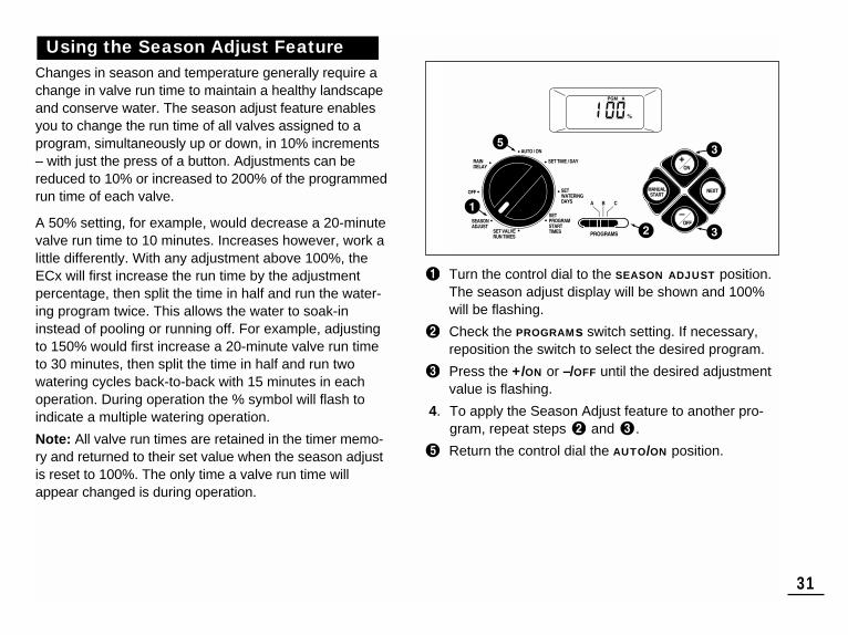
Changes in season and temperature generally require achange in valve run time to maintain a healthy landscapeand conserve water. The season adjust feature enablesyou to change the run time of all valves assigned to aprogram, simultaneously up or down, in 10% increments– with just the press of a button. Adjustments can bereduced to 10% or increased to 200% of the programmedrun time of each valve.
A 50% setting, for example, would decrease a 20-minutevalve run time to 10 minutes. Increases however, work alittle differently. With any adjustment above 100%, theECx will first increase the run time by the adjustmentpercentage, then split the time in half and run the water-ing program twice. This allows the water to soak-ininstead of pooling or running off. For example, adjustingto 150% would first increase a 20-minute valve run timeto 30 minutes, then split the time in half and run twowatering cycles back-to-back with 15 minutes in eachoperation. During operation the % symbol will flash toindicate a multiple watering operation.
Note: All valve run times are retained in the timer memo-ry and returned to their set value when the season adjustis reset to 100%. The only time a valve run time willappear changed is during operation.
Turn the control dial to the SEASON ADJUST position.The season adjust display will be shown and 100%will be flashing.
Check the PROGRAMs switch setting. If necessary,reposition the switch to select the desired program.
Press the +/ON or –/OFF until the desired adjustmentvalue is flashing.
4. To apply the Season Adjust feature to another pro-gram, repeat steps and .
Return the control dial the AUTO/ON position.
Using the Season Adjust Feature
31

A 0.75 Amp fuse protects the controller from damage dueto power surges and excessive current draw through theZone Modules. Before replacing the fuse, check for theprobable cause, such as a shorted or improperly connect-ed control valve wire, then replace the fuse as follows:
1 Shut off power to the timer at the source .
2. Remove the lower housing cover from the controller.
3. Carefully remove the blown fuse from the retainingclip. (See page 5 item 8 for fuse location.)
4. Remove the replacement fuse (attached to the insidelower corner of the door) and install it into the fuseretaining clip.
5. Install the lower housing cover.
6. Apply power to the timer.
1. Turn the control dial to the OFF position.
2. Remove the lower front cover from the timer housingby sliding it downward.
3. Place the back of the zone module squarely betweenthe guides of the first open expansion slot (from left toright). Pushing lightly on the bottom of the module,slide it upward until it locks into position.
4. To connect the valve wires, refer to “Connecting TheValves” on page 24.
5. Install the lower front cover.
6. To set the valve run time, refer to “Setting Valve RunTimes” on page 21.
7. To test the operation of the new watering zone(s),refer to “Manual Operation” on page 28.
Adding a Zone Module
Replacing the Fuse
Service and Specifications
32
WARNING:For continued protection against risk of fire,replace only with the same type and rating of fuse.Shut off the timer power source prior to servicingthe fuse. Failure to comply may result in injuryand/or controller damage.
24HR
12H
R
7 4 3 2 1 8

33
If you are having a problem with the timer, check the following symptoms, possible causes and remedies. If the problem cannot be resolved or you would like assistance with any Toro irrigation product, call our toll-free Toro Help Line, 1-800-367-8676 Monday through Friday, 7:30 AM – 4:00 PM (Pacific Standard Time).
Troubleshooting
Possible Cause
The battery is dead and one or moreof the following causes:
Blown fuse.
Open circuit breaker at service panel.
Watering programs have overlappingschedules.
Faulty control valve wire connections.
Valve run time is turned Off.
Control valve problem.
More than one start time on the program.
Season Adjust setting greater than100%.
Remedy
Replace the battery and one ormore of the following:
Replace the fuse. See page 32.
Reset circuit breaker.
Shorten valve run times and/orspace start times farther apart.
Check the wire connections at thecontrol valve and timer.
Enter a valve run time. See page 21.
Inspect, clean and repair valve asneeded.
Remove additional program starttimes. See page 20.
Set Season Adjust to 100%. Seepage 31.
Symptom
The display is blank and thetimer does not operate.
Watering programs start atunscheduled times.
Watering zone does not turn on.
Watering zone does not turn off.
Program restarts unexpectedlyafter the completion of an auto-matic operation.

Cabinet Dimensions:13.25" W x 9" H x 3.5" D (33.7cm W x 22.9cm H x 9cm D)Transformer Specifications:Class 2, UL Listed, CSA Certified (or equivalent)• Input: 120 V a.c. 60 Hz, 0.5A• Output: 24 V a.c. 60 Hz, 20 VA Maximum Load Per Zone: 0.35 Amps @ 24 V a.c. Maximum Load For Pump/Master Valve: 0.35 Amps @ 24 V a.c. Total Maximum Output: (One valve plus pump or master valve),not to exceed 0.70 Amps @ 24 V a.c. Fuse: 0.75 Amp, 3AG – Protects AC ReturnBattery Type and Back-Up Duration (approximate):9-Volt Alkaline – 72 hrs. or 9-Volt Ni-MH – 24 hrs.Temperature Limit Range:Operating – 14°F to 140°F (-10°C to 60°C)Storage – -22°F to 149°F (-30°C to 65°C)
This equipment has been tested and found to comply with the limits for aClass B digital device, pursuant to Part 15 of the FCC Rules. These limits aredesigned to provide reasonable protection against harmful interference in aresidential installation. This equipment generates, uses and can radiate radiofrequency energy and, if not installed and used in accordance with the instruc-tions, may cause harmful interference to radio communications. However,there is no guarantee that interference will not occur in a particular installation.If this equipment does harmful interference to radio or television reception,which can be determined by turning the equipment off and on, the user isencouraged to try to correct the interference by one or more of the followingmeasures:1. Reorient or relocate the receiving antenna.2. Increase the separation between the equipment and receiver.3. Connect the equipment into an outlet on a circuit different from that to
which the receiver is connected.4. Consult the dealer or an experienced radio/TV technician for help.The user may find the following booklet prepared by the Federal Communica-tions Commission helpful:“How To Identify and Resolve Radio-TV Interference Problems”. This bookletis available from the U.S. Government Printing Office, Washington, DC 20402.Stock No. 004-000-00345-4.
The Toro Promise – Limited One Year Warranty
The Toro Company and its affiliate, Toro Warranty Company, pursuant to anagreement between them, jointly warrants, to the owner, against defects inmaterial and workmanship for a period of one year from the date of purchase.
Neither The Toro Company nor Toro Warranty Company is liable for failure ofproducts not manufactured by it even though such products may be sold orused in conjunction with Toro products.
During such warranty period, we will repair or replace, at our option, any partfound to be defective.
Return the defective part to the place of purchase.
This warranty does not apply where equipment is used, or installation is per-formed, in any manner contrary to Toro’s specifications and instructions, norwhere equipment is altered or modified.
NEITHER THE TORO COMPANY NOR TORO WARRANTY COMPANY ISLIABLE FOR INDIRECT, INCIDENTAL OR CONSEQUENTIAL DAMAGES INCONNECTION WITH THE USE OF EQUIPMENT, INCLUDING BUT NOTLIMITED TO: VEGETATION LOSS, THE COST OF SUBSTITUTE EQUIP-MENT OR SERVICES REQUIRED DURING PERIODS OF MALFUNCTIONOR RESULTING NON-USE, PROPERTY DAMAGE OR PERSONAL INJURYRESULTING FROM INSTALLER’S NEGLIGENCE.
Some states do not allow the exclusion or limitation of incidental or conse-quential damages, so the above limitation or exclusion may not apply to you.
ALL IMPLIED WARRANTIES, INCLUDING THOSE OF MERCHANTABILITYAND FITNESS FOR USE, ARE LIMITED TO THE DURATION OF THISEXPRESS WARRANTY.
Some states do not allow limitations of how long an implied warranty lasts, sothe above limitation may not apply to you.
This warranty gives you specific legal rights and you may have other rightswhich vary from state to state.
Warranty
FCC Rules
Specifications
© 2002 The Toro Company, Irrigation Division, An ISO 9001-Certified Facility Form Number 373-0191 Rev. B


![Performance Implications of Anti- Virus Execution on a ... · mov edx, dword ptr 0xb0[ebp] inc ecx add eax, 0xc cmp ecx, edx mov dword ptr 0xd4[ebp], ecx jl 0xf45cc81a PC-Cillin mov](https://static.fdocuments.in/doc/165x107/5e0c75705b1bef31eb23074f/performance-implications-of-anti-virus-execution-on-a-mov-edx-dword-ptr-0xb0ebp.jpg)


![AGeneralApproachforEfficiently ...• DAG"Representa3on" • Express"root"nodes"in"terms"of"leaf"nodes" 1:#mov#ecx,#esi 2:#movzxb#eax,#al 3:#shl#ecx,#0x5 4:#add#edx,0x1 5:#lea#esi,#ptr#[ecx+esi]](https://static.fdocuments.in/doc/165x107/602b4d4a1a86145e4a0431a7/ageneralapproachforeifciently-a-dagrepresenta3on-a-expressrootnodesintermsofleafnodes.jpg)