New developments in offshore precise GNSS positioning
106
New developments in offshore precise GNSS positioning www.fugro.com Kees de Jong Fugro Intersite B.V. November 2013
Transcript of New developments in offshore precise GNSS positioning
New developments in offshore precise GNSS positioning
www.fugro.com
Kees de JongFugro Intersite B.V.
November 2013
Contents
�����
����� ����
����������������������������������������������������
������ ����������
www.fugro.com
����� ������������������ �������������

Profile
www.fugro.com
Mission is to be the world’s leading service-provider in the collection and interpretation of data relating to the Earth’s surface and sub-surface, and in the support of infrastructure developments on land, at the coast and on the seabed.

Survey services
www.fugro.com
Fugro provides the energy sector, commercial and engineering industries, governments and other agencies with offshore survey and geospatial services tailored to the specific needs of each client.

Geotechnical services
www.fugro.com
Fugro investigates the engineering properties and geologic characteristics of near-surface soils and rocks, advises on foundation design and provides construction materials testing, pavement management and installation support.

Subsea services
www.fugro.com
Fugro’s subsea capabilities range from supporting exploration drilling, provision of support services for field construction, inspections and interventions on subsea infrastructure to design and build of complex remote systems and tools.

Seabed geosolutions joint venture
www.fugro.com
A Fugro/CGG joint venture, seabed geosolutions acquires, processes, interprets and monitors geophysical data from seabed-positioned technologies to help oil and gas clients optimise field development and production.

Client sectors
Mining Building and infrastructureOil and gas
www.fugro.com
g gg
Sustainable energy Public sector Other sectors

We deliver critical knowledge and essential operational support to the upstream and downstream oil and gas industry, providing a true life-of-field solution from exploration and development through to production and decommissioning.
Our knowledge, expertise and resources play a vital role in the development of sustainable energy solutions, both onshore and offshore, furthering new ways of meeting future energy demands.
We help mining companies to recover raw materials efficiently and safely, using a range of survey, mapping, investigation and sampling technologies, together with geoconsulting services.
We contribute to the design, realisation, safety and integrity of construction and development projects through the collection, interpretation, application and management of data relating to natural and man-made environments.
Client sectors
www.fugro.com
man made environments.
Our mapping and data management services help local, regional and national government agencies manage urban planning, security, natural resources and environmental emergencies. Responsible strategies mean a safer future for all.
In sectors as diverse as agriculture, water supply and control, forestry and fishing, Fugro’s technical expertise helps ensure the future of communities, as well as conserving our planet.
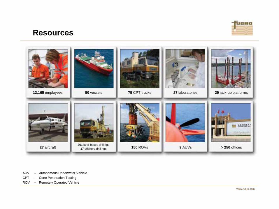
Resources
50 vessels 75 CPT trucks 27 laboratories 29 jack-up platforms12,165 employees
www.fugro.com
AUV – Autonomous Underwater VehicleCPT – Cone Penetration Testing ROV – Remotely Operated Vehicle
27 aircraft261 land-based drill rigs
17 offshore drill rigs > 250 offices150 ROVs 9 AUVs

Offshore positioning
www.fugro.com
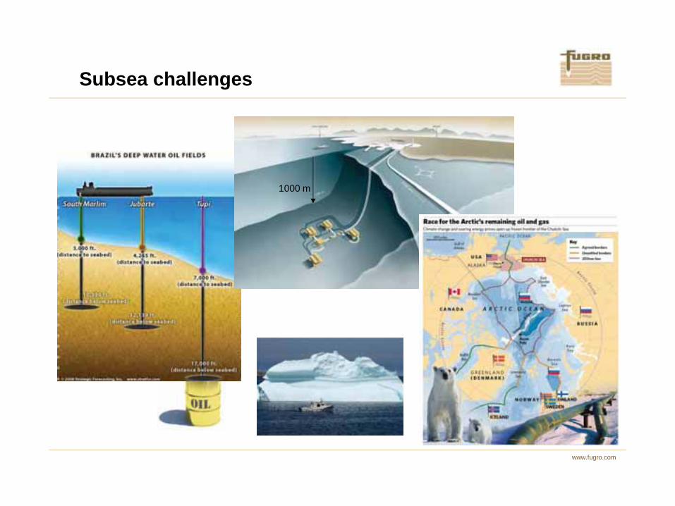
Subsea challenges
1000 m
www.fugro.com
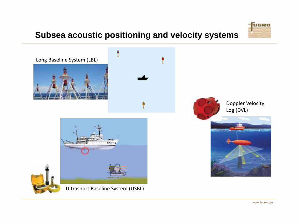
Subsea acoustic positioning and velocity systems
����������� ���������
���������������
���������
www.fugro.com
��������� ������ ������ ���
� � �

Ultra Short Baseline (USBL) system
- Observations: distance and angles
- Precision: 0.1-0.5% of water depth
- Low update rate
Subsea acoustic positioning – USBL
www.fugro.com

An Ultra Short Baseline (USBL) system is portable and therefore popular for offshore use. It consists of a transponder on a subsea vehicle, such as an ROV (Remotely Operated Vehicle) and a transceiver on the surface vessel. Measurements are ranges (actually two-way travel times) and angles, which are used to determine the 3D position difference of the ROV with respect to the vessel. Adding the vessel’s absolute position gives the ROV’s absolute position.
The precision of a USBL depends on the water depth: for deep water, ranges are long and a small error in an angle propagates directly into the position difference. A USBL therefore needs to be properly calibrated, i.e., its attitude needs to be properly known.
Update rate is low, as speed of sound is low (1500 m/s). For example, for a water depth of 3000 m, it takes 4 seconds for an acoustic signal to travel from surface vessel to ROV and back. As a result,
Subsea acoustic positioning – USBL
www.fugro.com
update rate in this case is once every four seconds (or less).
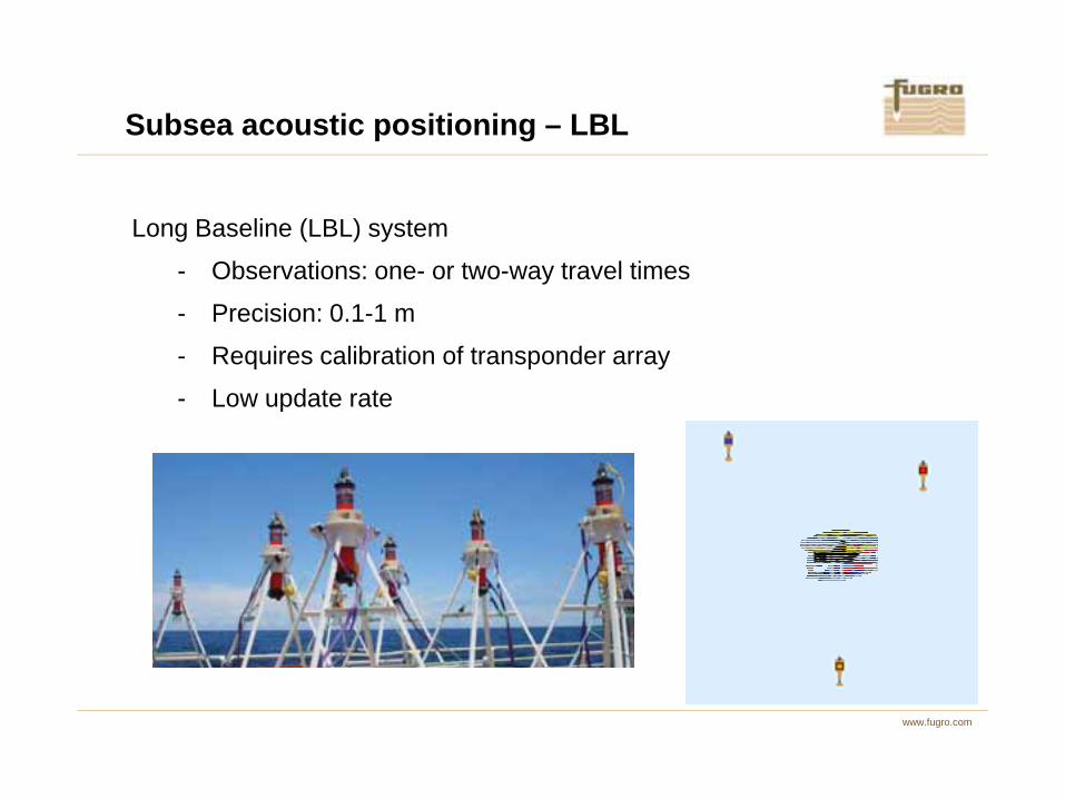
Subsea acoustic positioning – LBL
Long Baseline (LBL) system
- Observations: one- or two-way travel times
- Precision: 0.1-1 m
- Requires calibration of transponder array
- Low update rate
www.fugro.com
- Low update rate
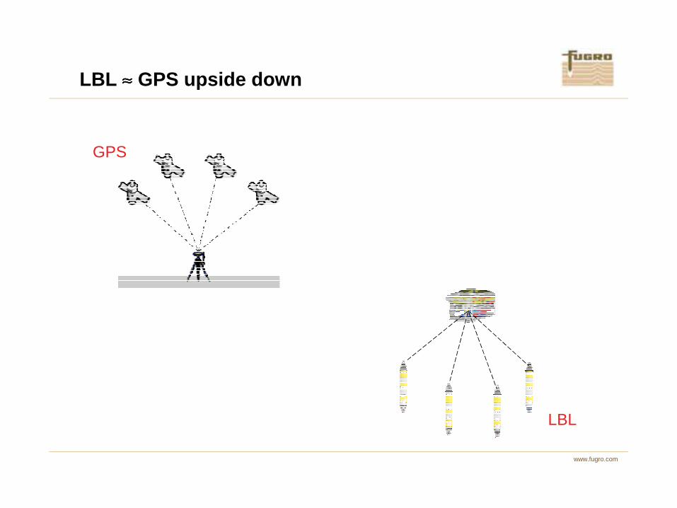
LBL ≈≈≈≈ GPS upside down
GPS
www.fugro.com
LBLLBL

A Long Baseline (USBL) system can be considered as GPS upside down. It consists of transponders at known locations on the seabed and a transceiver on a subsea vehicle, such as an ROV (Remotely Operated Vehicle). Measurements consist of ranges (actually two way travel times) between vehicle and transponders. Positions are determined using trilateration.
Positions of the transponders are determined from a calibration procedure, where a surface vessel sails a pattern above the transponders and measures the ranges between transponder and vessel. Together with the known absolute position of the vessel, usually from GPS, the absolute positions of the transponders are determined. To further strengthen the network, it is often also possible to measure distances between transponders.
Subsea acoustic positioning – LBL
www.fugro.com
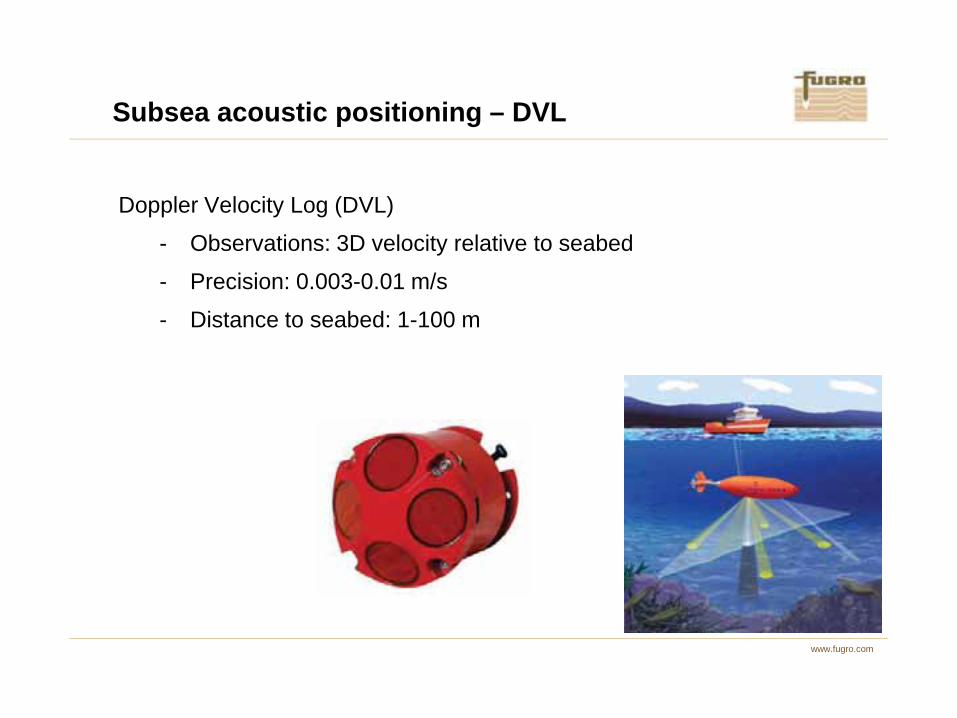
Doppler Velocity Log (DVL)
- Observations: 3D velocity relative to seabed
- Precision: 0.003-0.01 m/s
- Distance to seabed: 1-100 m
Subsea acoustic positioning – DVL
www.fugro.com

A Doppler Velocity Log (DVL) uses four acoustic beams to measure velocity relative to the seabed. These four velocities are derived from the Doppler shift between DVL and seabed.
The four beam velocities are transformed to three velocity components in the DVL’s body frame. Using the attitude of the DVL or the vehicle on which it is mounted, it is possible to transform these velocities into an Earth fixed navigation frame, such as north, east and up.
Subsea acoustic positioning – DVL
www.fugro.com
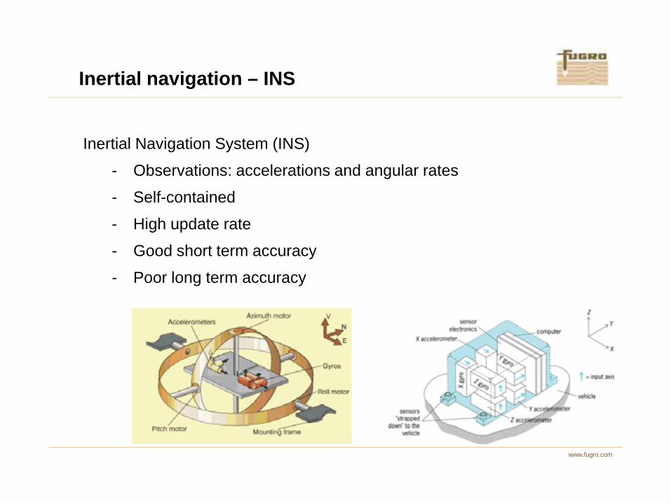
Inertial Navigation System (INS)
- Observations: accelerations and angular rates
- Self-contained
- High update rate
- Good short term accuracy
Inertial navigation – INS
www.fugro.com
- Good short term accuracy
- Poor long term accuracy

Inertial navigation – INS
Velocity Position3D acceleration
(body frame)
Transformation from body to navigation frame
Correct for Earth’s gravity
∫ ∫
www.fugro.com
3D angular rate
Attitude
y g
Body frame : Fixed to sensorNavigation frame : Usually North, East, Up
Inertial Measurement Unit (IMU)
Inertial Navigation System (INS)
∫

An Inertial Navigation System (INS) consists of an Inertial Measurement Unit (IMU) and a computer to estimate position, velocity, attitude and a number of (hardware) biases.
An IMU consists of three accelerometers and three gyroscopes to measure accelerations and angular rates. Integrating these quantities gives velocity and angular differences, integrating the velocity differences gives position differences. The accelerations are given in the IMU’s body frame. The integrated angular data is used to compute attitude in a global navigation frame, such as north, east, up and to transform the body-fixed velocities and positions to this frame as well.
An IMU is self-contained and does not need any external sensors. However, it is a dead reckoning system, which means that only position, velocity and attitude differences can be determined. Using a special calibration is it possible to determine the initial attitude, whereas absolute initial position and
Inertial navigation – INS
www.fugro.com
velocity can be obtained from e.g. GPS.
Also, although an IMU is very stable for short periods, it drifts considerably after longer periods (km/hour). Aiding an IMU with other sensors, like GPS, will eliminate the drift or at least keep it within bounds.
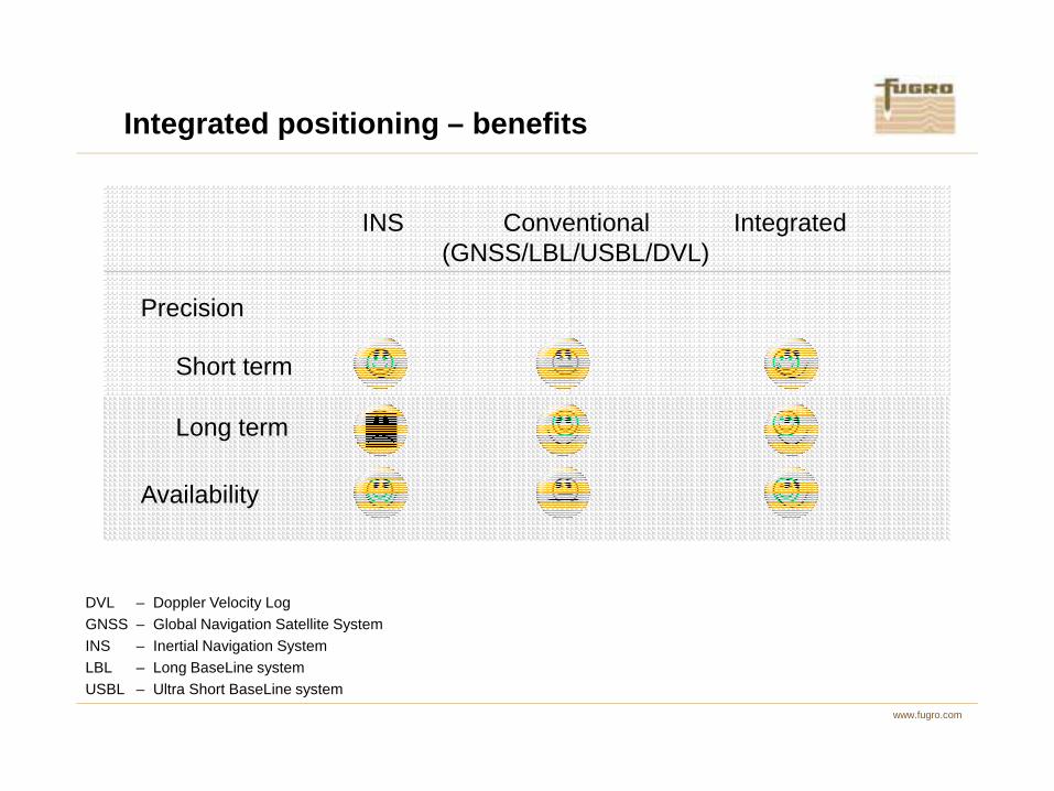
Integrated positioning – benefits
INS Conventional Integrated(GNSS/LBL/USBL/DVL)
Precision
Short term ☺ � ☺
www.fugro.com
DVL – Doppler Velocity LogGNSS – Global Navigation Satellite SystemINS – Inertial Navigation SystemLBL – Long BaseLine systemUSBL – Ultra Short BaseLine system
Long term � ☺ ☺
Availability ☺ � ☺
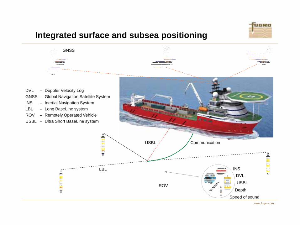
Integrated surface and subsea positioningGNSS
DVL – Doppler Velocity LogGNSS – Global Navigation Satellite SystemINS – Inertial Navigation SystemLBL – Long BaseLine system
www.fugro.com
INSDVL
USBL
Depth
USBL
LBL
Communication
ROV – Remotely Operated VehicleUSBL – Ultra Short BaseLine system
ROV
Speed of sound
In integrated positioning systems data from different sensors are combined to provide a single solution. Sensors are chosen in such a way that if one fails, the others can still provide a reliable solution. Precision is important, but perhaps even more important is availability.
Data from different sensors is in general used in a Kalman filter. Such a filter estimates (corrections to) position, velocity, attitude, gyro and accelerometer biases and scale factors, speed of sound, misalignment errors, etc.
Integrated positioning filter can become very complex. Care should be taken that all parameters are in fact estimable, that proper dynamical and stochastic models are used. If this is not the case, the filter may diverge.
Integrated positioning
www.fugro.com
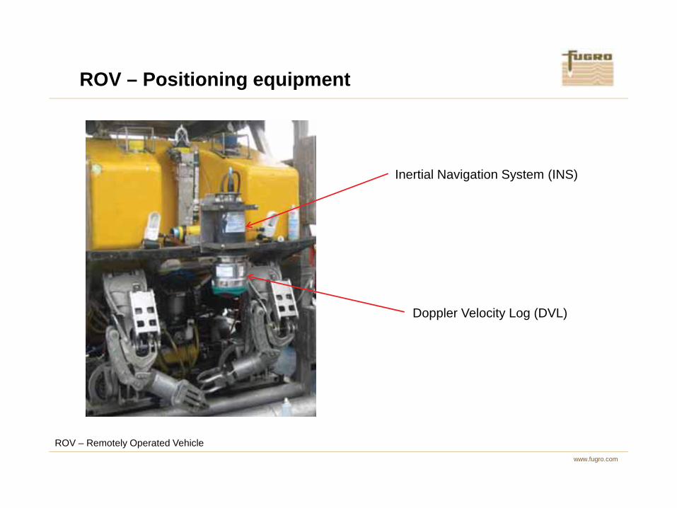
ROV – Positioning equipment
Inertial Navigation System (INS)
www.fugro.com
Doppler Velocity Log (DVL)
ROV – Remotely Operated Vehicle

Contents
�����
����� ����
����������������������������������������������������
������ ����������
www.fugro.com
����� ������������������ �������������

Current GNSS services
Service Accuracy Correction source
Navigation satellites
Signalfrequencies
Positioning mode
L1 Meter Referencestations GPS Single Differential
HP Decimeter Referencestations GPS Dual Differential
www.fugro.com
EPlus Sub-meter Orbit & clock
GPS &GLONASS
Single PPP
XP Decimeter Orbit & clock GPS Dual PPP
G2 Decimeter Orbit & clockGPS &
GLONASSDual PPP
GNSS – Global Navigation Satellite SystemPPP – Precise Point Positioning

L1 and HP are examples of DGNSS (Differential GNSS (Global Navigation Satellite System, such as GPS, Glonass, Galileo and BeiDou)) service. Differential positioning uses reference stations at known locations to compute the distance between these stations and the GNSS satellites. The difference between observed and computed distance is considered to be a bias and used as a correction for mobile stations in an area up to several hundred kilometers around the reference stations. Biases can be due to errors in the satellite position and clock and the atmsophere(troposphere and ionosphere).
XP, G2 and EPlus are PPP (Precise Point Position) services. For PPP no differential corrections are used. Instead, a sparse global network of reference stations is used to compute precise satellite orbits and clocks in real-time. These precise orbits and clocks are valid worldwide and used at a mobile which besides position also needs to estimate atmospheric parameters (it can also eliminate
Current GNSS services
www.fugro.com
mobile, which besides position, also needs to estimate atmospheric parameters (it can also eliminate ionospheric parameters by using a linear combination of data from different frequencies).

Infrastructure
L1 and HP
www.fugro.com
G2
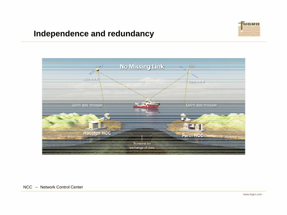
Independence and redundancy
www.fugro.com
NCC – Network Control Center
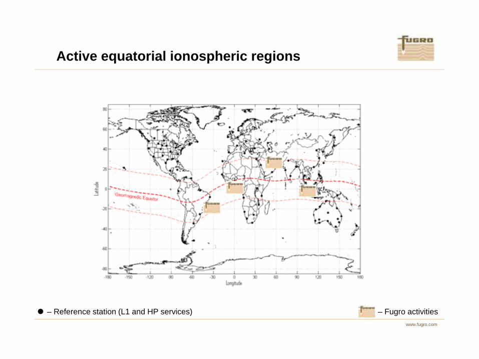
Active equatorial ionospheric regions
www.fugro.com
– Reference station (L1 and HP services) – Fugro activities
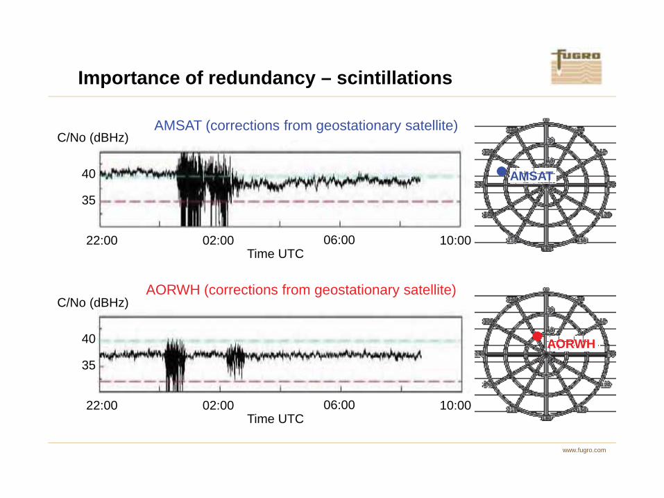
Importance of redundancy – scintillations
AMSAT (corrections from geostationary satellite)
10:00
35
22:00 02:00 06:00
40
C/No (dBHz)
Ti UTC
AMSAT
www.fugro.com
AORWH
Time UTC
10:00
35
22:00 02:00 06:00
40
C/No (dBHz)
Time UTC
AORWH (corrections from geostationary satellite)
Fugro broadcasts GNSS corrections from geostationary satellites using L-band frequencies. The figure on the previous slide shows tracking of the GNSS corrections in Rio for two different geostationary satellites on 20 October 2011. Rio is located in the center of the two polar plots on the right.
The receiver repeatedly looses lock and then re-acquires the signals, probably due to scintillations. This goes on for about two hours. One of the satellites, AMSAT (AMerican SATellite), at an elevation of 25 degrees and an azimuth of 285 degrees is affected more frequent then the other satellite, AORWH (Atlantic Ocean Region West, High), which is at 61 degrees elevation and 333 degrees azimuth. What is also typical is that they are not affected at the same time, because they are at different places in the sky. This shows the importance of redundancy.
Importance of redundancy – scintillations
www.fugro.com

StarPack
GNSS observations and corrections
NTRIP client
Second receiver and antenna (optional)
www.fugro.com
GNSS – Global Navigation Satellite SystemNTP – Network Time ProtocolNTRIP – Network Transport of RTCM via Internet Protocol
NTP
Output to networkStorage of data
Web interface

StarPack – web interface
www.fugro.com

StarTrack – Seismic streamer positioning
www.fugro.com
Positioning of gun floatand tail buoy
UHF antenna
GNSS antenna
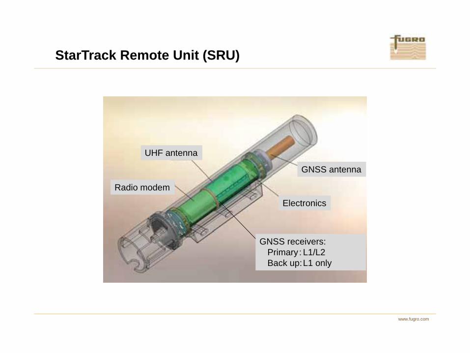
StarTrack Remote Unit (SRU)
www.fugro.com
Radio modem
Electronics
GNSS receivers:Primary: L1/L2Back up:L1 only

Web interface
www.fugro.com

Precise Point Positioning (PPP) services
Service Accuracy Correction source
Navigation satellites
Satellite frequencies
EPlus Sub-meter Orbit & clock
GPS &GLONASS
Single
www.fugro.com
XP Decimeter Orbit & clock GPS Dual
G2 Decimeter Orbit & clockGPS &
GLONASSDual

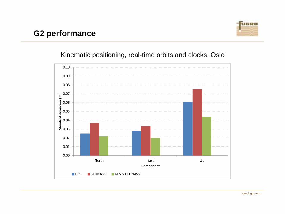
G2 performance
����
����
����
����
����
������ ��
Kinematic positioning, real-time orbits and clocks, Oslo
www.fugro.com
����
����
���
���
����
����
���� ���� ��
������������
���������
��� ��� ��� ��������� ��� ��������� ��������� !"�������#$��%&'()

G2 performance
Kinematic positioning, real-time orbits and clocks, Oslo
����
����
����
����
����
������ ��
www.fugro.com
����
����
���
���
����
����
���� ���� ��
������������
���������
��� ��� ��� ��������� ��� ��������� ��������� !"�������#$��%&'()
G2 performance
Kinematic positioning, real-time orbits and clocks, Oslo
����
����
����
����
����
������ ��
www.fugro.com
����
����
���
���
����
����
���� ���� ��
������������
���������
��� ��� ��� ��������� ��� ��������� ��������� !"�������#$��%&'()
Contents
�����
����� ����
����������������������������������������������������
������ ����������
www.fugro.com
����� ������������������ �������������
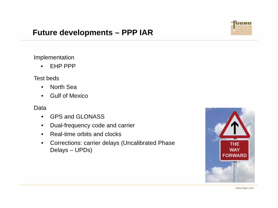
Implementation• EHP PPP
Test beds • North Sea• Gulf of Mexico
Future developments – PPP IAR
www.fugro.com
Data• GPS and GLONASS• Dual-frequency code and carrier• Real-time orbits and clocks• Corrections: carrier delays (Uncalibrated Phase
Delays – UPDs)
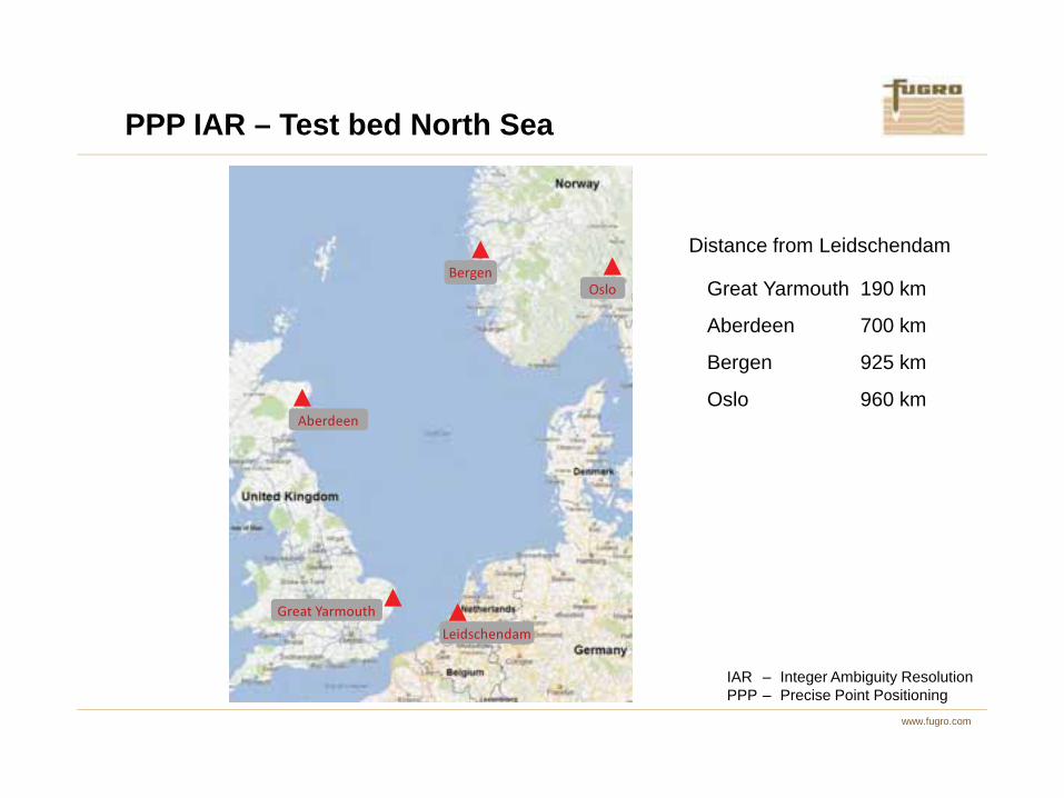
Distance from Leidschendam
Great Yarmouth 190 km
Aberdeen 700 km
Bergen 925 km
Oslo 960 km
����
����
PPP IAR – Test bed North Sea
www.fugro.com
Oslo 960 km
��� ���� ��
���� ��
��������������
IAR – Integer Ambiguity ResolutionPPP – Precise Point Positioning
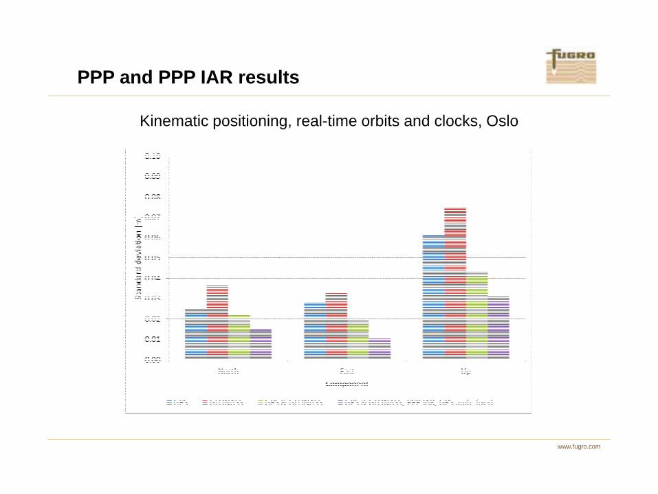
PPP and PPP IAR results
Kinematic positioning, real-time orbits and clocks, Oslo
www.fugro.com
Region 1
Region 4
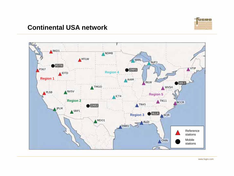
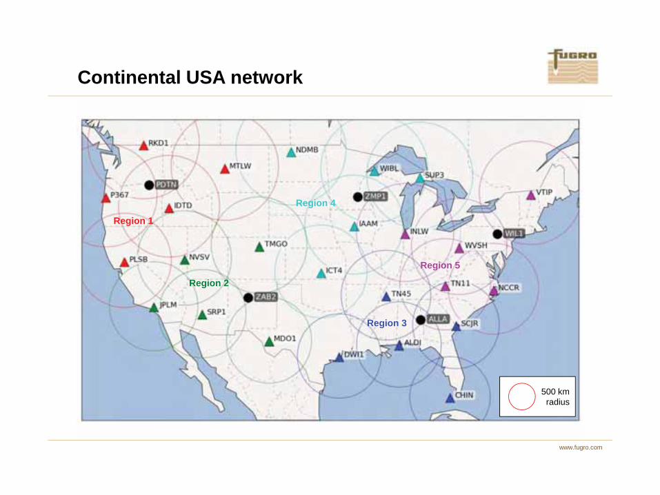
Continental USA network
www.fugro.com
Region 2
Region 3
Region 5
Referencestations
Mobilestations
Region 1
Region 4
Continental USA network
www.fugro.com
Region 2
Region 3
Region 5
500 kmradius

PPP IAR results
www.fugro.com
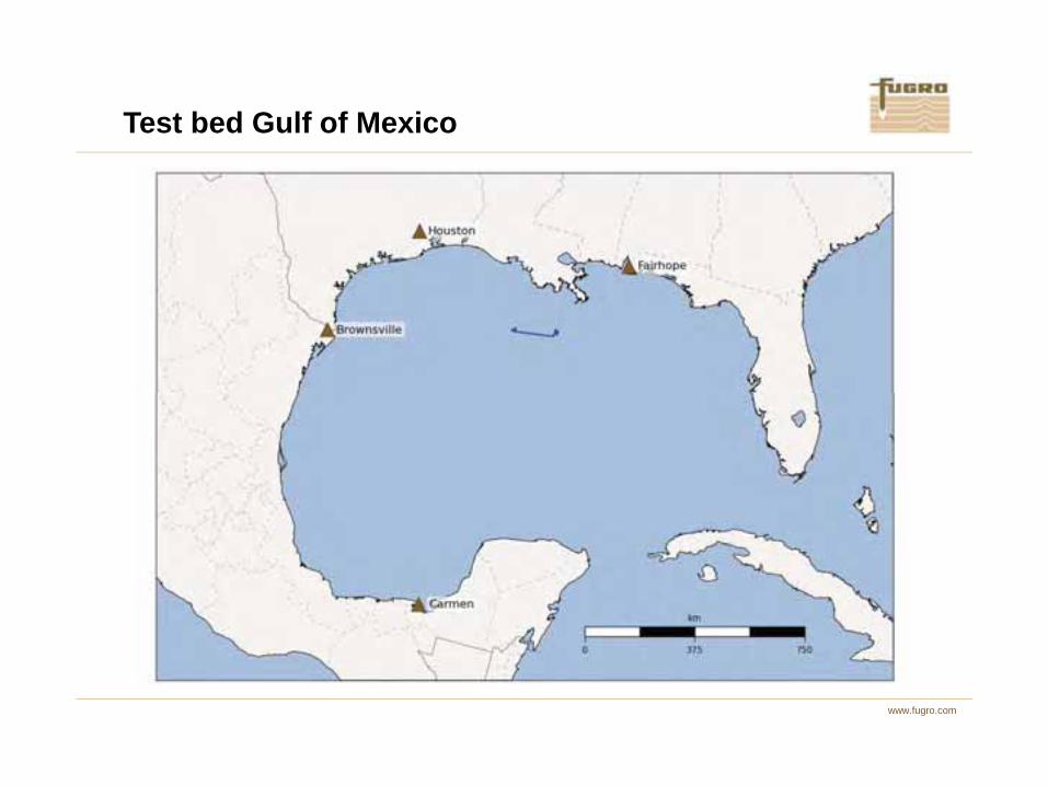
Test bed Gulf of Mexico
www.fugro.com

Comparing different sources of UPDs
www.fugro.com

• Dynamic environment with real-time solution.
• One antenna mounted
• Two instances of a PPP IAR solution with different sources of UPDs
Carmen Fairhope
Comparing different sources of UPDs
www.fugro.com
UPDs.
– e.g. Carmen and Fairhope
• Difference in east, north and height components calculated
PPP-RTKInstance(Carmen)
PPP-RTKInstance
(Fairhope)
Differencecalculated

Comparing different sources of UPDs
www.fugro.com
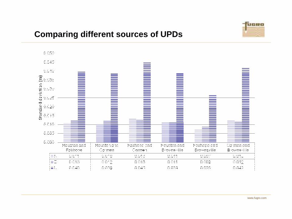
Comparing different sources of UPDs
www.fugro.com

Contents
�����
����� ����
����������������������������������������������������
������ ����������
www.fugro.com
����� ������������������ �������������

BeiDou and Galileo – satellites
������ ���� ���
�������� ��� �� � �� ��� ���
�������� ������ ����� ����� ������ ��
www.fugro.com
� � � � � � � �
��������� � �� ��!�!�"� ���#��"� ���#��"� �$#���"� �##���"�
�%&��%����% ��� �� ��� �#� ���
����������%� � � � � #
����� ���������������� �������������������

BeiDou and Galileo – signal frequencies
������ ���� ���
'� ��#�(�$! �� ����(�� )� ����(��
www.fugro.com
'� ����(�� ��� ���#(�� )� ����(#�
'� ��#!(�� ��� ����(�� )� ���#(��
�� ��$�(�$�
!�����"��������#$%
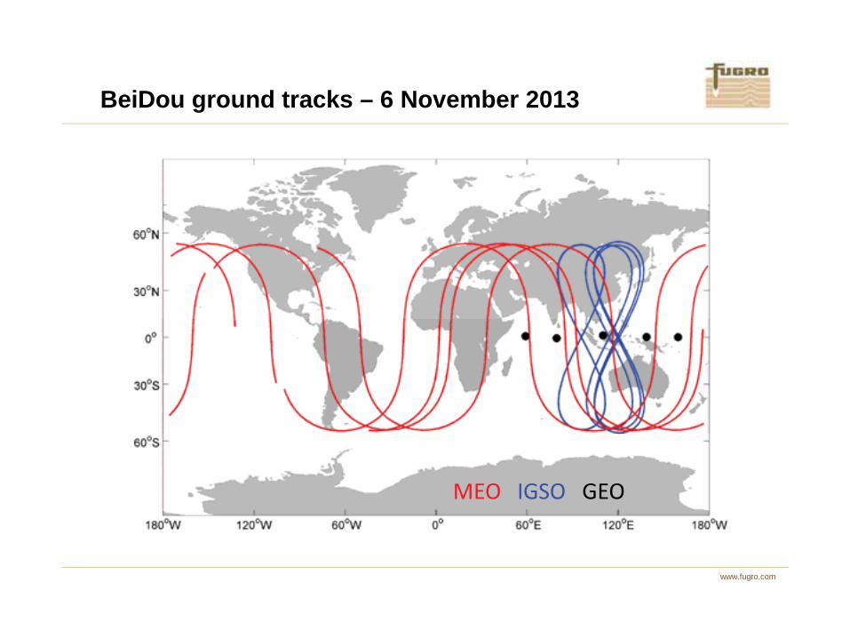
BeiDou ground tracks – 6 November 2013
www.fugro.com
����������������

Singapore – ground tracks and visible satellites
www.fugro.com
�� ( #
��%( �
�*��% ��� ( �
��%( �
�*��% �
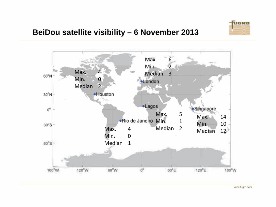
BeiDou satellite visibility – 6 November 2013
www.fugro.com
�� ( �
��%( �
�*��% �
�� ( ��
��%( ��
�*��% ��
�� ( �
��%( �
�*��% �
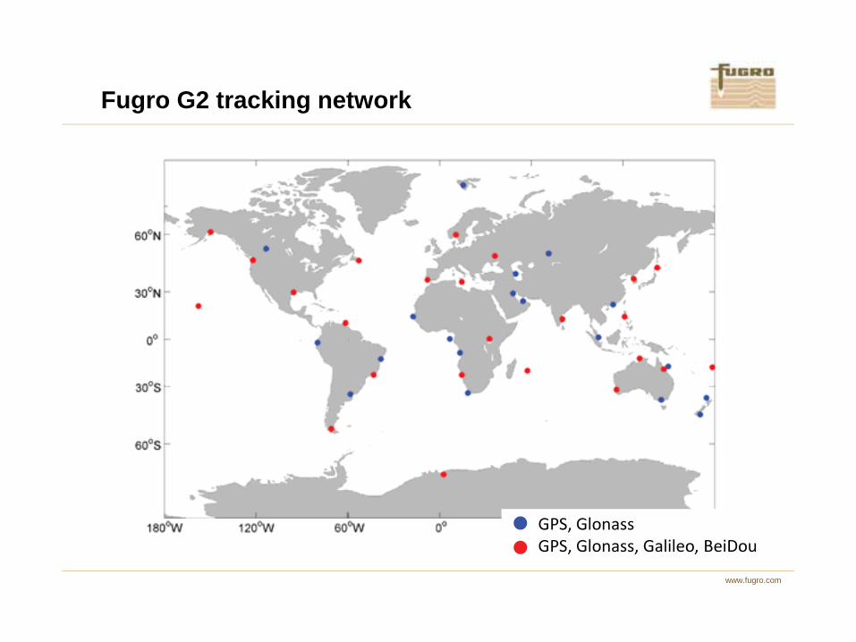
Fugro G2 tracking network
www.fugro.com
+�,� ��%���
+�,� ��%���,� �����,�'�-�.

IGS MGEX tracking network
www.fugro.com
+�,� ��%���,� �����
+�,� ��%���,� �����,�'�-�.
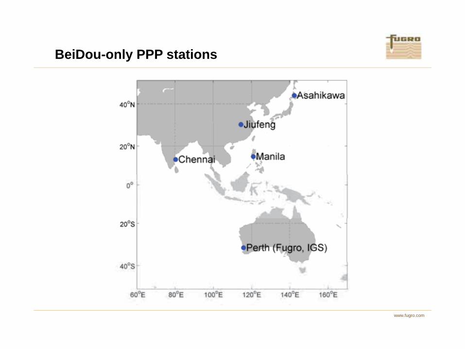
BeiDou-only PPP stations
www.fugro.com
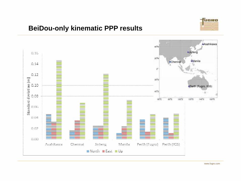
BeiDou-only kinematic PPP results
www.fugro.com

GPS+Galileo PPP station
www.fugro.com
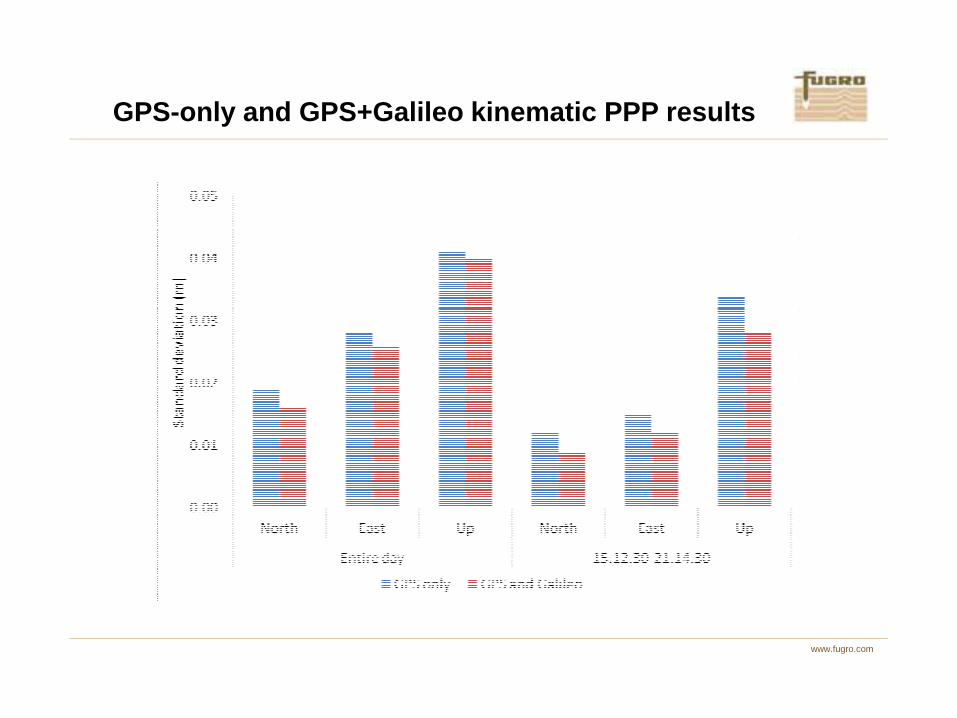
GPS-only and GPS+Galileo kinematic PPP results
www.fugro.com
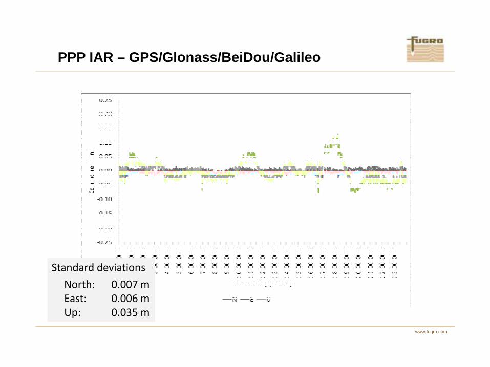
PPP IAR – GPS/Glonass/BeiDou/Galileo
www.fugro.com
��������� �������
����� !"!!#�
$��� !"!!%�
&� !"!'(�

PPP IAR convergence times – GPS only-.���/�0.%&�� +�,�&.��%��&�%��������%,�$$($1��.&&������
www.fugro.com
��%2���
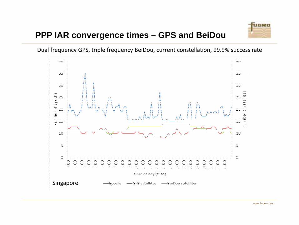
PPP IAR convergence times – GPS and BeiDou-.���/�0.%&�� +�,������/�0.%&��'�-�.,�&.��%��&�%��������%,�$$($1��.&&������
www.fugro.com
��%2���
Contents
�����
����� ����
����������������������������������������������������
������ ����������
www.fugro.com
����� ������������������ �������������

www.fugro.com
Sunspot 1302, Sep 2011

Sunspot region 1302, Sep 24, 2011
www.fugro.com
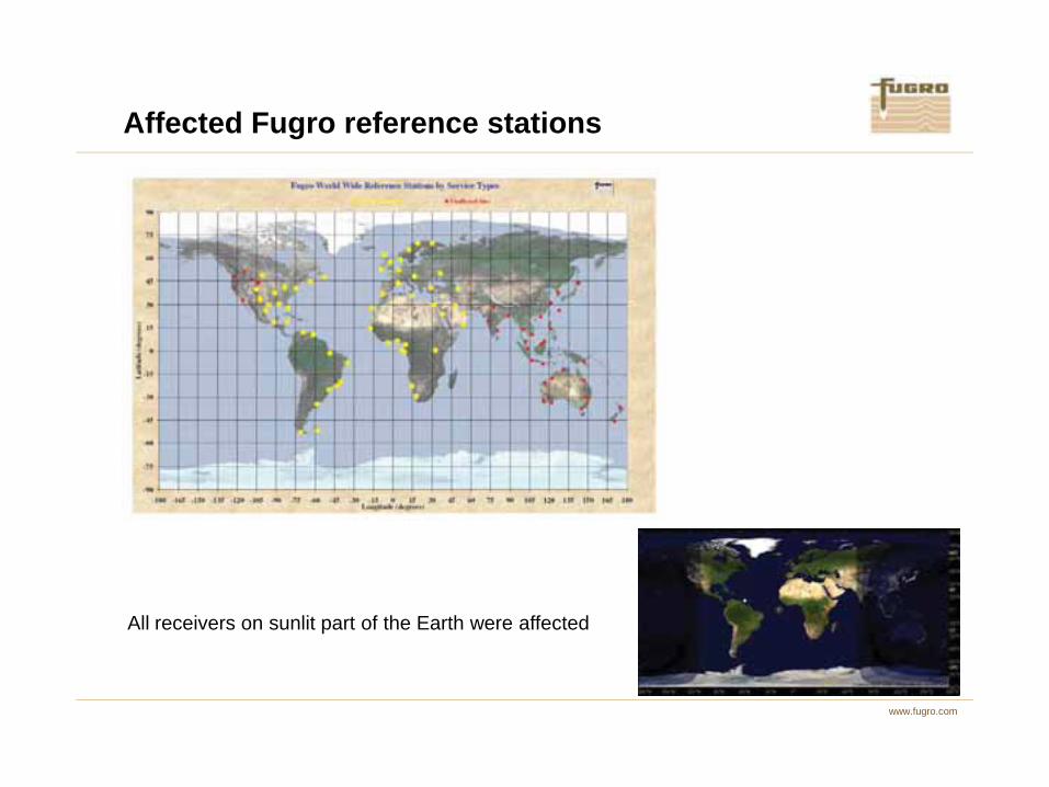
Affected Fugro reference stations
www.fugro.com
All receivers on sunlit part of the Earth were affected

L-band tracking EUSAT, Sep 24
www.fugro.com
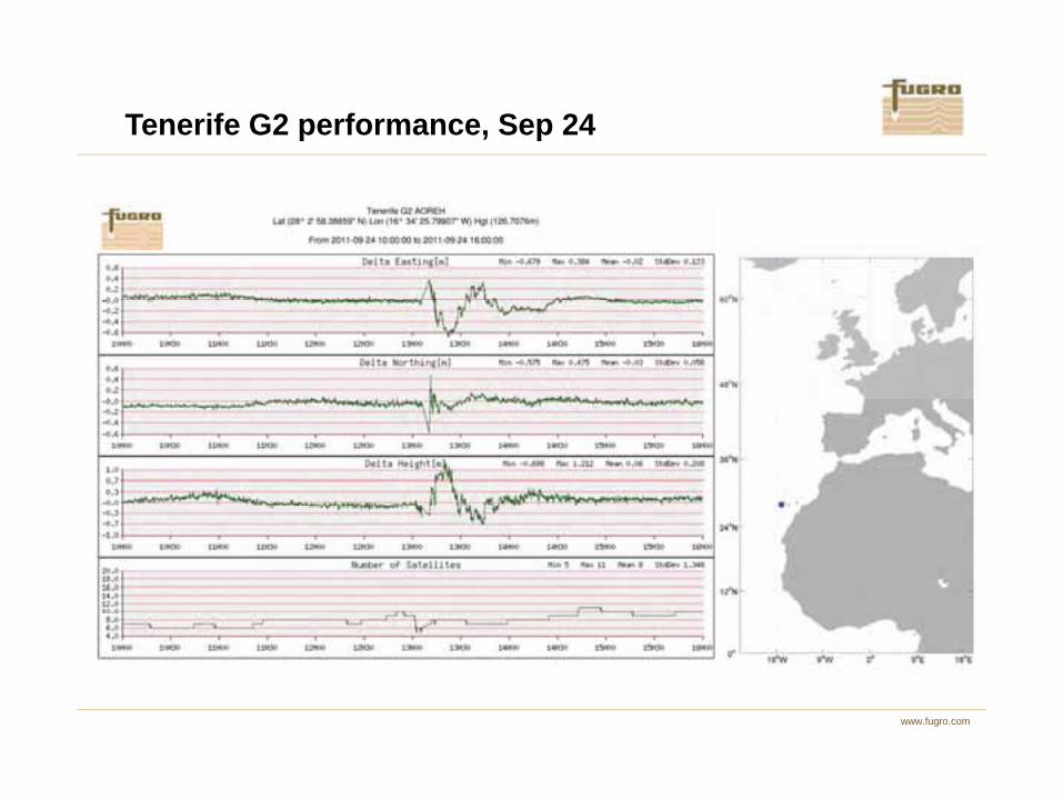
Tenerife G2 performance, Sep 24
www.fugro.com

GPS tracking Oslo, Sep 24GPS C/No, Oslo NRS, 24 Sept 2011
40
45
50
55
60
No
G03,L1G03,L2G05,L1
G05,L2G06,L1G06,L2
G13,L1G13,L2G16,L1
www.fugro.com
10
15
20
25
30
35
12:30:00.0 12:40:00.0 12:50:00.0 13:00:00.0 13:10:00.0 13:20:00.0
Time UTC
C/N
,
G16,L2G21,L1G21,L2
G29,L1G29,L2G30,L1
G30,L2G31,L1G31,L2
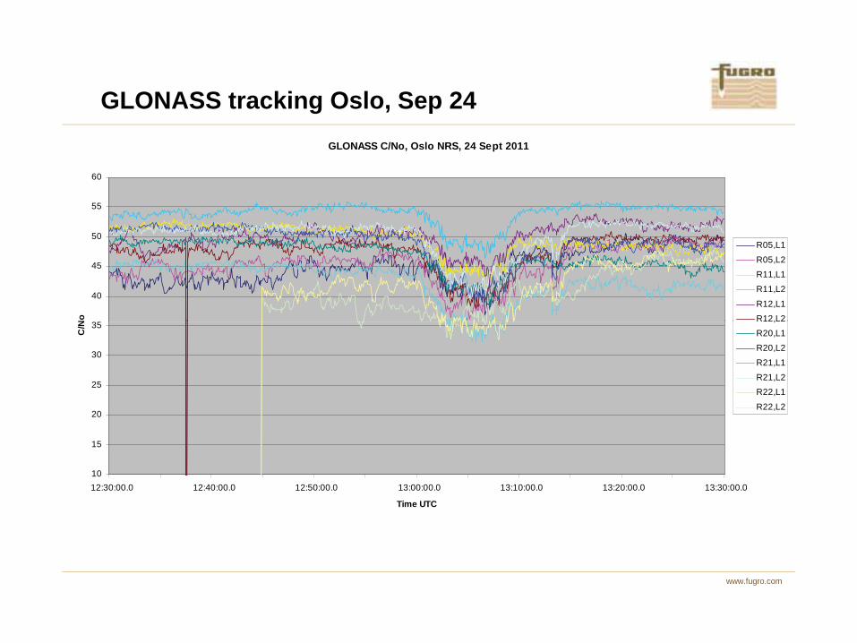
GLONASS tracking Oslo, Sep 24GLONASS C/No, Oslo NRS, 24 Sept 2011
40
45
50
55
60
No
R05,L1
R05,L2R11,L1R11,L2
R12,L1R12,L2
www.fugro.com
10
15
20
25
30
35
12:30:00.0 12:40:00.0 12:50:00.0 13:00:00.0 13:10:00.0 13:20:00.0 13:30:00.0
Time UTC
C/N
,R20,L1R20,L2
R21,L1R21,L2R22,L1
R22,L2
www.fugro.com
Scintillation monitors
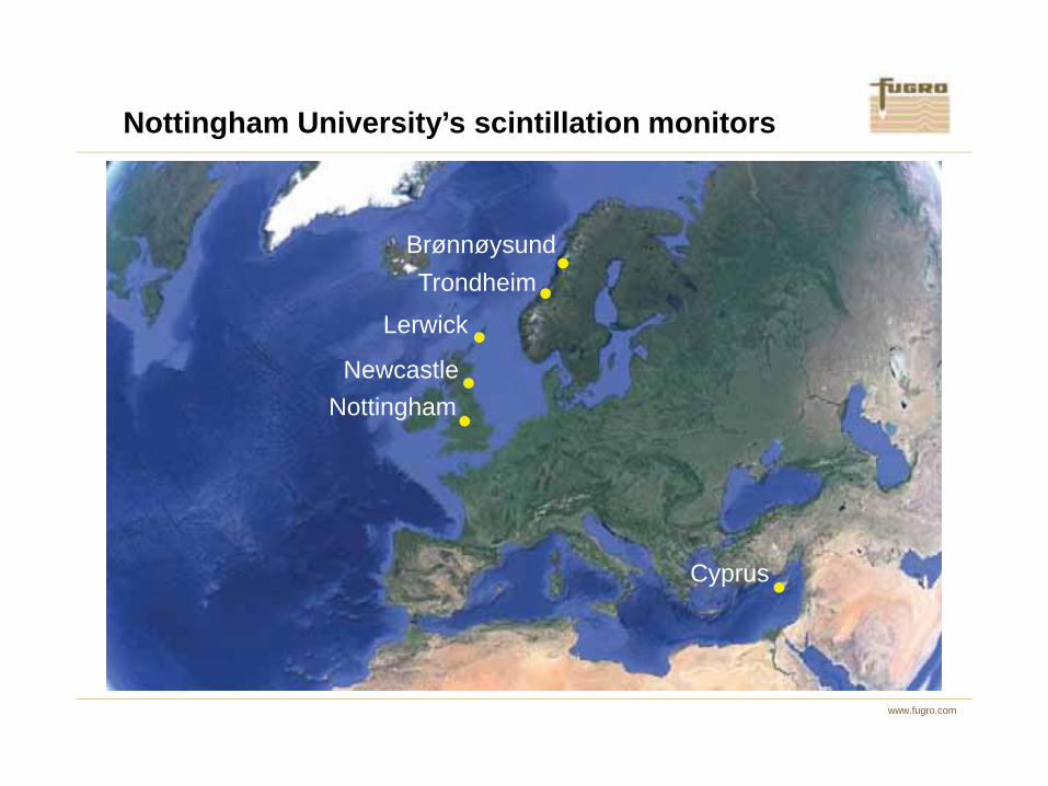
Nottingham University’s scintillation monitors
Lerwick
Newcastle
TrondheimBrønnøysund
www.fugro.com
Nottingham
Cyprus
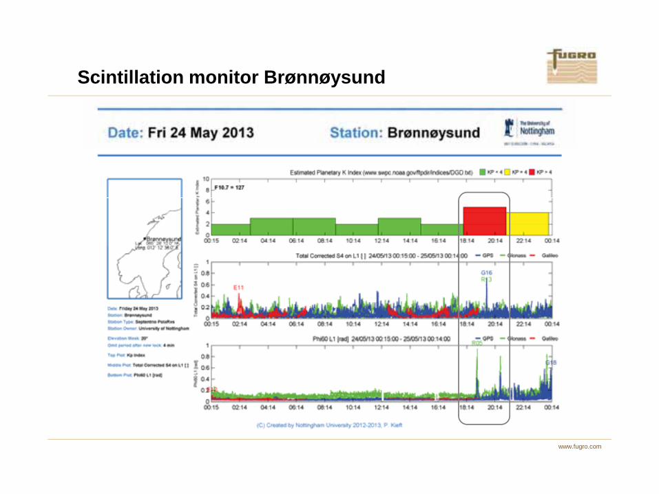
Scintillation monitor Brønnøysund
www.fugro.com
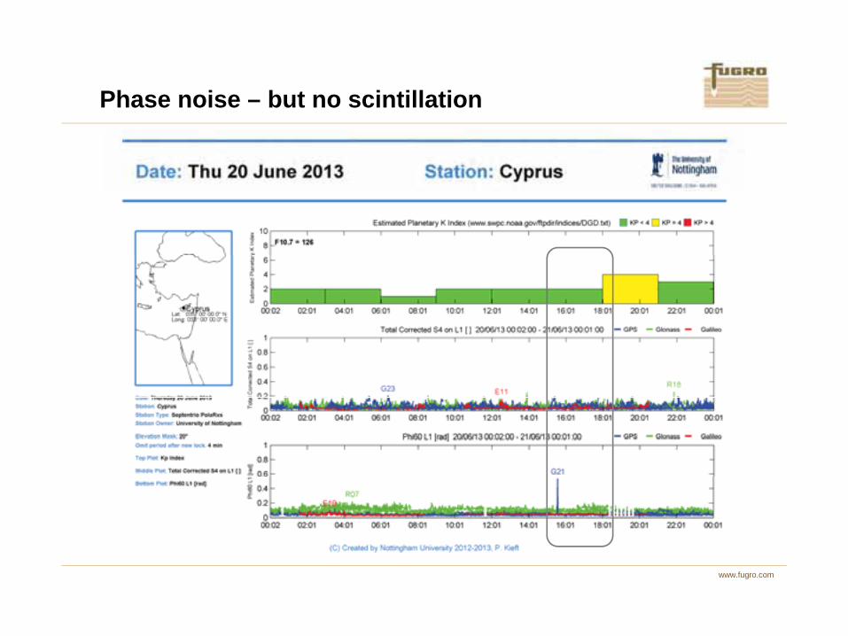
Phase noise – but no scintillation
www.fugro.com

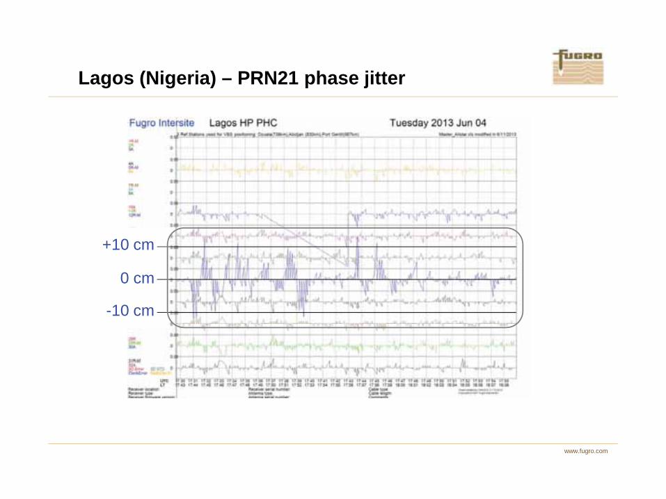
Lagos (Nigeria) – height errors due to PRN21
www.fugro.com
+10 cm
Lagos (Nigeria) – PRN21 phase jitter
www.fugro.com
0 cm
10 cm
-10 cm

www.fugro.com
Ionospheric scintillation

Scintillation frequency at solar maximum
100 days/year
130
www.fugro.com
Map taken from: Kintner et al, GNSS and ionospheric scintillation – How to survive the next solar maximum. InsideGNSS, July/August 2009.
Less than 10 days/year
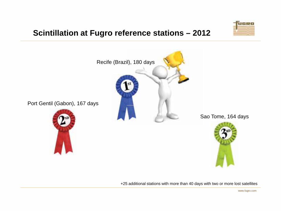
Scintillation at Fugro reference stations – 2012
Port Gentil (Gabon), 167 days
Recife (Brazil), 180 days
www.fugro.com
( ), y
Sao Tome, 164 days
+25 additional stations with more than 40 days with two or more lost satellites

Plasma bubbles diffract and refract GNSS signals leading to
- Phase scintillation (phase jittering, characterized by )
- Amplitude scintillation (rapid fluctuations in the signal intensity fading amplitude, characterized by S4)
resulting in degraded GNSS receiver performance
- Signal power loss (or even loss of lock)
- Increased measurement noise level
Ionospheric scintillation
60ϕσ
www.fugro.com
Increased measurement noise level
Notes:
- Amplitude scintillation is more common at equatorial regions
- Phase scintillation is more common at high latitudes
- More severe at lower frequencies

- Use L1&L2 phase and code at 1 s interval to compute
- Compute
- Convert to phase delay on L1 [rad/s]
- Compute by mapping slant to vertical
)(3.40)(1
tTECfc
tL
Δ⋅⋅
=ϕ
Computation of scintillation indices
)1()()( −−=Δ tTECtTECtTEC
VTECΔVTECΔ
TEC
www.fugro.com
- Standard deviation of over every 60 seconds is the phase scintillation index along signal path between receiver and satellite
- Standard deviation of SNR values over 60 seconds is the amplitude scintillation index
along signal path between receiver and satellite
60ϕσϕ
4S
VTEC irregularities (TECU)
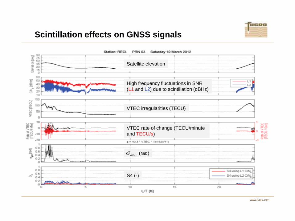
Scintillation effects on GNSS signals
High frequency fluctuations in SNR (L1 and L2) due to scintillation (dBHz)
Satellite elevation
www.fugro.com
(rad)60ϕσ
g ( )
VTEC rate of change (TECU/minute and TECU/s)
S4 (-)
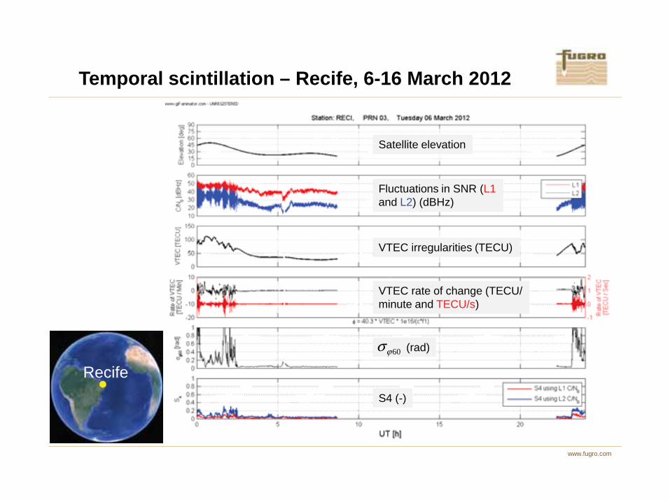
Temporal scintillation – Recife, 6-16 March 2012
VTEC irregularities (TECU)
Fluctuations in SNR (L1and L2) (dBHz)
Satellite elevation
www.fugro.com
Recife
(rad)60ϕσ
VTEC irregularities (TECU)
VTEC rate of change (TECU/minute and TECU/s)
S4 (-)
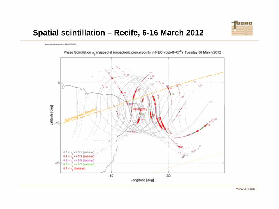
Spatial scintillation – Recife, 6-16 March 2012
www.fugro.com

24 hour scintillation prediction using four reference stations in Brazil for user location Lat = 10°S and Lon = 38°W
Scintillation prediction – Initial results
www.fugro.com
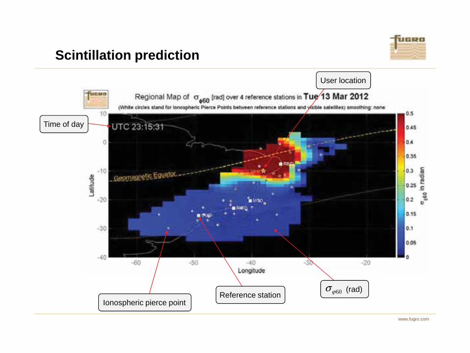
Time of day
User location
Scintillation prediction
www.fugro.com
Ionospheric pierce pointReference station
(rad)60ϕσ

Actual position error Number of satellites
Scintillation prediction
www.fugro.com
Predicted position error at previous epochs Predicted position error
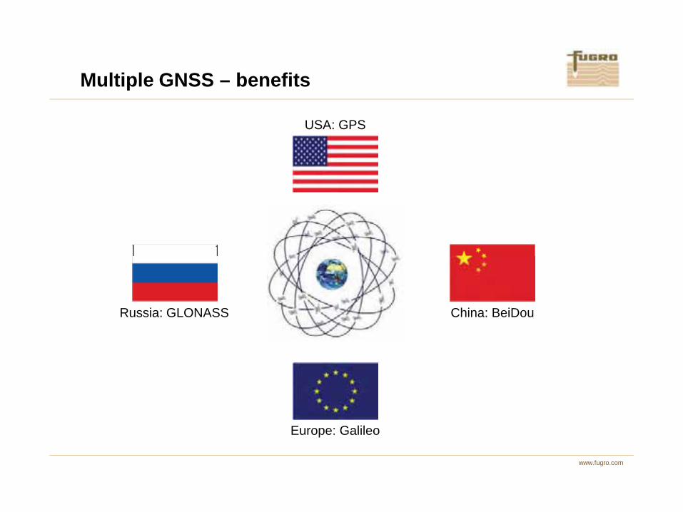
Multiple GNSS – benefits
USA: GPS
www.fugro.com
Russia: GLONASS
Europe: Galileo
China: BeiDou
The US GPS and Russian Glonass are operational Global Navigation Satellite Systems (GNSS). Europe is developing Galileo, China BeiDou. BeiDou currently (2013) consists of 15 satellites, for Galileo there are four satellites in orbits. Once all systems are operational, there will be more than 100 satellites available for precise positioning.
Even though the current Galileo and BeiDou constellations are not complete, they already help in case satellite signal reception is disrupted, due e.g. to scintillations, as will be shown on the following slides.
GPS and GPS/Glonass solutions show anomalies between 18:00-19:00. The situation improves when BeiDou is added (Galileo does not contribute to this improvement, as no satellites are available for this period).
Multiple GNSS
www.fugro.com
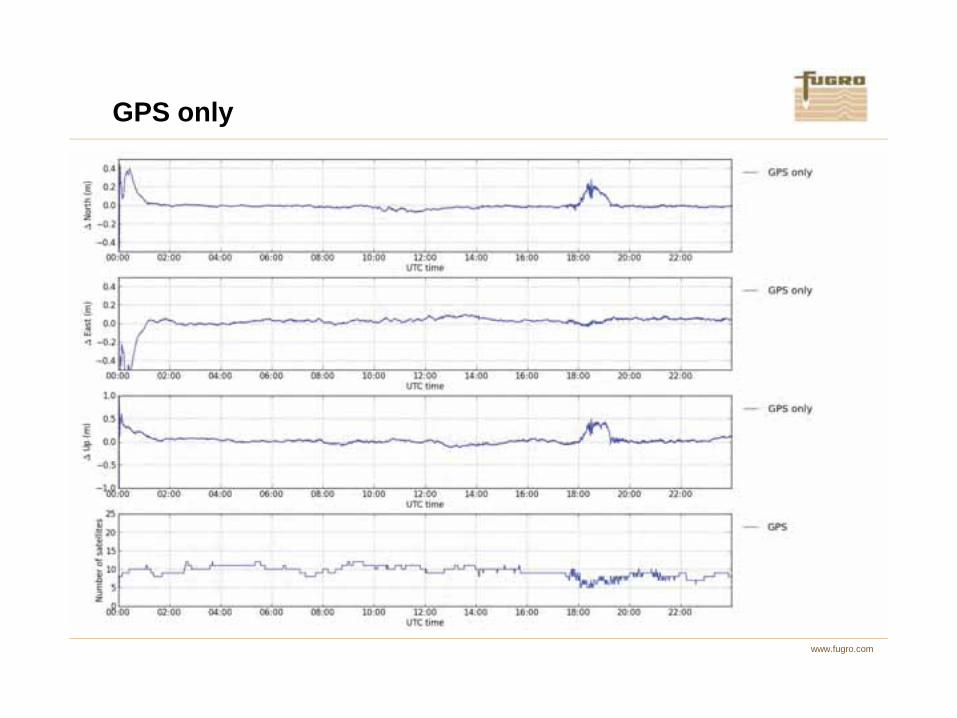
GPS only
www.fugro.com

GPS and Glonass
www.fugro.com

GPS, Glonass and Galileo
www.fugro.com

GPS, Glonass and BeiDou
www.fugro.com
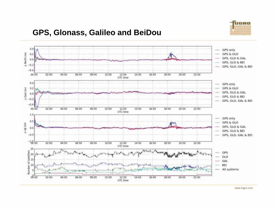
GPS, Glonass, Galileo and BeiDou
www.fugro.com
• Multiple satellite positioning systems
• More and stronger GNSS signals
• Redundant networks, data links and positioning services
• Monitor and predict ionospheric disturbances
Mitigating increased solar activity
www.fugro.com

Conclusions
www.fugro.com
Fugro delivers precise positioning services for a wide variety of offshore activities, using a highly redundant infrastructure and in-house developed hard- and software.
www.fugro.com
Thank you