
New Developments in Gear Hobbing - Gear Technology · the chamfering can be done on a standard...
8
www.geartechnology.com March/April 2010 GEAR TECHNOLOGY 45 Management Summary Several innovations have been introduced to the gear manufacturing industry in recent years. In the case of gear hobbing—the dry cutting technology and the ability to do it with powder-metallurgical HSS—might be two of the most impressive ones. And the technology is still moving forward. The aim of this article is to present recent develop- ments in the field of gear hobbing in conjunction with the latest improvements regarding tool materials, process tech- nology and process integration. continued Figure 1—Tool improvements in the past. Introduction A couple of newer developments have been introduced regarding gear hobbing; i.e., the innovations in the substrate materials and coating systems have led to an increase of pro- ductivity by higher cutting speeds and longer tool life. But we all know that higher performance leads to higher prices for the tools, so the impact on the tool investment as well as the resulting cost-per-piece have to be examined. Another perspective to improve productivity is to shorten the process chain. Here, the process integration via cham- fering and deburring on the hobbing machine is discussed. Beyond conventional chamfering methods like the Gratomat principle or rotary deburring, a new process using specially designed chamfering cutters will be presented. Finally, the chance for cost savings by process substi- tution is discussed, focusing on examples for finish hob- bing. To overcome shaving as the traditional soft-finishing method, new tool concepts are presented that aim to increase the process performance regarding tool life and workpiece quality. Of equal importance, the ability to eliminate or control the natural twist of finish hobbing might lead to new applications. Modern Tool Design Machine tools have also improved considerably in the last decades, but their major impact on hobbing technol- ogy was related to tool development. If we examine those past improvements, the focus was, on the one hand, on the substrate materials and, on the other hand, on the coating systems (Fig. 1). Together, both developments led to much higher cutting speeds and/or longer tool life. Even processes like dry hobbing became a reality. Coming from the conventional HSS substrates (e.g., EMo5Co5 or M35) with TiN coating, the use of carbide New Developments in Gear Hobbing Dr. Oliver Winkel (Printed with permission of the copyright holder, the American Gear Manufacturers Association, 500 Montgomery Street, Suite 350, Alexandria, Virginia 22314-1560. Statements presented in this paper are those of the author(s) and may not repre- sent the position or opinion of the American Gear Manufacturers Association.) hobs seemed to be critical to dry hobbing applications. But after initial success, problems with the process’s reliability regarding tool life of the reconditioned carbide hobs (e.g., due to cobalt leaching during stripping) stopped the trend. Then, the introduction of the more heat-resistant TiAlN coatings—in combination with higher alloyed and more homogeneous PM-HSS substrates—brought the dry cutting back on track. Today, dry cutting with PM-HSS, as well as carbide, is a given. And since the AlCrN-based coatings have recently been introduced successfully in the gear hob- bing market, speed and feed could be increased even more in many applications. Besides their more homogeneous structure, the main advantage of the powder metallurgical HSS substrates is the ability to contain greater amounts of alloys. As shown
Transcript of New Developments in Gear Hobbing - Gear Technology · the chamfering can be done on a standard...
www.geartechnology.com March/April 2010 GEARTECHNOLOGY 45
Management Summary Several innovations have been introduced to the gear manufacturing industry in recent years. In the case of gear
hobbing—the dry cutting technology and the ability to do it with powder-metallurgical HSS—might be two of the most impressive ones. And the technology is still moving forward. The aim of this article is to present recent develop-ments in the field of gear hobbing in conjunction with the latest improvements regarding tool materials, process tech-nology and process integration.
continued
Figure 1—Tool improvements in the past.
IntroductionA couple of newer developments have been introduced
regarding gear hobbing; i.e., the innovations in the substrate materials and coating systems have led to an increase of pro-ductivity by higher cutting speeds and longer tool life.
But we all know that higher performance leads to higher prices for the tools, so the impact on the tool investment as well as the resulting cost-per-piece have to be examined.
Another perspective to improve productivity is to shorten the process chain. Here, the process integration via cham-fering and deburring on the hobbing machine is discussed. Beyond conventional chamfering methods like the Gratomat principle or rotary deburring, a new process using specially designed chamfering cutters will be presented.
Finally, the chance for cost savings by process substi-tution is discussed, focusing on examples for finish hob-bing. To overcome shaving as the traditional soft-finishing method, new tool concepts are presented that aim to increase the process performance regarding tool life and workpiece quality. Of equal importance, the ability to eliminate or control the natural twist of finish hobbing might lead to new applications.
Modern Tool DesignMachine tools have also improved considerably in the
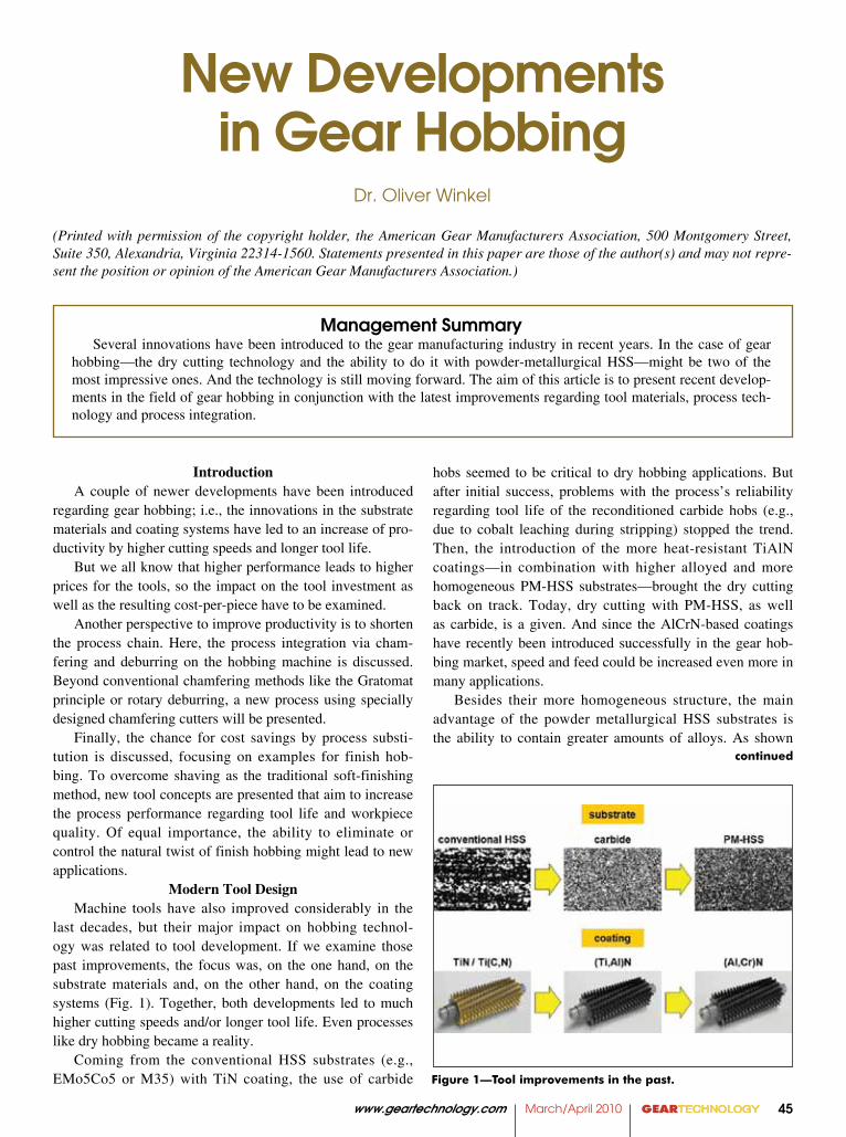
last decades, but their major impact on hobbing technol-ogy was related to tool development. If we examine those past improvements, the focus was, on the one hand, on the substrate materials and, on the other hand, on the coating systems (Fig. 1). Together, both developments led to much higher cutting speeds and/or longer tool life. Even processes like dry hobbing became a reality.
Coming from the conventional HSS substrates (e.g., EMo5Co5 or M35) with TiN coating, the use of carbide
New Developments in Gear Hobbing
Dr. Oliver Winkel
(Printed with permission of the copyright holder, the American Gear Manufacturers Association, 500 Montgomery Street, Suite 350, Alexandria, Virginia 22314-1560. Statements presented in this paper are those of the author(s) and may not repre-sent the position or opinion of the American Gear Manufacturers Association.)
Figure 1. Tool improvements in the past
hobs seemed to be critical to dry hobbing applications. But after initial success, problems with the process’s reliability regarding tool life of the reconditioned carbide hobs (e.g., due to cobalt leaching during stripping) stopped the trend. Then, the introduction of the more heat-resistant TiAlN coatings—in combination with higher alloyed and more homogeneous PM-HSS substrates—brought the dry cutting back on track. Today, dry cutting with PM-HSS, as well as carbide, is a given. And since the AlCrN-based coatings have recently been introduced successfully in the gear hob-bing market, speed and feed could be increased even more in many applications.
Besides their more homogeneous structure, the main advantage of the powder metallurgical HSS substrates is the ability to contain greater amounts of alloys. As shown
GEARTECHNOLOGY March/April 2010 www.geartechnology.com46
Figure 3—Properties of modern coating systems.
Figure 4—Costs for different coatings.
Figure 5—PM-HSS versus carbide.
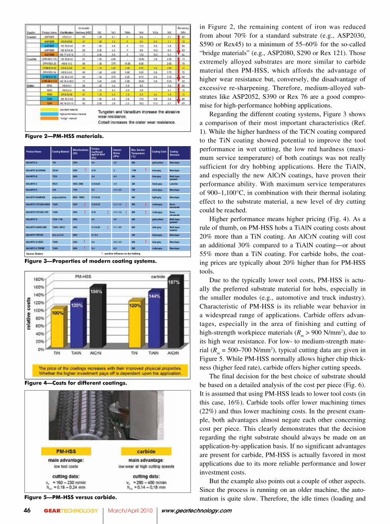
in Figure 2, the remaining content of iron was reduced from about 70% for a standard substrate (e.g., ASP2030, S590 or Rex45) to a minimum of 55–60% for the so-called “bridge materials” (e.g., ASP2080, S290 or Rex 121). Those extremely alloyed substrates are more similar to carbide material then PM-HSS, which affords the advantage of higher wear resistance but, conversely, the disadvantage of excessive re-sharpening. Therefore, medium-alloyed sub-strates like ASP2052, S390 or Rex 76 are a good compro-mise for high-performance hobbing applications.
Regarding the different coating systems, Figure 3 shows a comparison of their most important characteristics (Ref. 1). While the higher hardness of the TiCN coating compared to the TiN coating showed potential to improve the tool performance in wet cutting, the low red hardness (maxi-mum service temperature) of both coatings was not really sufficient for dry hobbing applications. Here the TiAlN, and especially the new AlCrN coatings, have proven their performance ability. With maximum service temperatures of 900–1,100°C, in combination with their thermal isolating effect to the substrate material, a new level of dry cutting could be reached.
Higher performance means higher pricing (Fig. 4). As a rule of thumb, on PM-HSS hobs a TiAlN coating costs about 20% more than a TiN coating. An AlCrN coating will cost an additional 30% compared to a TiAlN coating—or about 55% more than a TiN coating. For carbide hobs, the coat-ing prices are typically about 20% higher than for PM-HSS tools.
Due to the typically lower tool costs, PM-HSS is actu-ally the preferred substrate material for hobs, especially in the smaller modules (e.g., automotive and truck industry). Characteristic of PM-HSS is its reliable wear behavior in a widespread range of applications. Carbide offers advan-tages, especially in the area of finishing and cutting of high-strength workpiece materials (R
m > 900 N/mm2), due to
its high wear resistance. For low- to medium-strength mate-rial (R
m = 500–700 N/mm2), typical cutting data are given in
Figure 5. While PM-HSS normally allows higher chip thick-ness (higher feed rate), carbide offers higher cutting speeds.
The final decision for the best choice of substrate should be based on a detailed analysis of the cost per piece (Fig. 6). It is assumed that using PM-HSS leads to lower tool costs (in this case, 16%). Carbide tools offer lower machining times (22%) and thus lower machining costs. In the present exam-ple, both advantages almost negate each other concerning cost per piece. This clearly demonstrates that the decision regarding the right substrate should always be made on an application-by-application basis. If no significant advantages are present for carbide, PM-HSS is actually favored in most applications due to its more reliable performance and lower investment costs.
But the example also points out a couple of other aspects. Since the process is running on an older machine, the auto-mation is quite slow. Therefore, the idle times (loading and
Figure 2—PM-HSS materials.
www.geartechnology.com March/April 2010 GEARTECHNOLOGY 47
continued
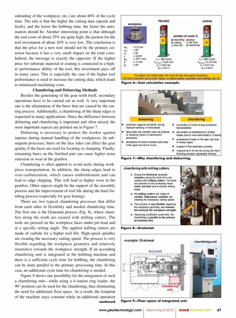
unloading of the workpiece, etc.) are about 40% of the cycle time. The rule is that the higher the cutting data (speeds and feeds), and the lower the hobbing time, the faster the auto-mation should be. Another interesting point is that although the tool costs of about 35% are quite high, the portion for the tool investment of about 10% is very low. The conclusion is that the price for a new tool should not be the primary cri-terion because it has a very small impact on the total costs. Indeed, the message is exactly the opposite: If the higher price for substrate material or coating is connected to a high-er performance ability of the tool, this investment pays off in many cases. This is especially the case if the higher tool performance is used to increase the cutting data, which leads to minimized machining costs.
Chamfering and Deburring MethodsBesides the generating of the gear teeth itself, secondary
operations have to be carried out as well. A very important one is the elimination of the burrs that are caused by the cut-ting process. Additionally, a chamfering of the sharp edges is requested in many applications. Since the difference between deburring and chamfering is important and often mixed, the most important aspects are pointed out in Figure 7.
Deburring is necessary to protect the worker against injuries during manual handling of the workpieces. In sub-sequent processes, burrs on the face sides can affect the gear quality if the faces are used for locating or clamping. Finally, remaining burrs on the finished part can cause higher noise emission or wear in the gearbox.
Chamfering is often applied to avoid nicks during work-piece transportation. In addition, the sharp edges lead to over-carburization, which causes embrittlement and can lead to edge chipping. This will lead to higher wear in the gearbox. Other aspects might be the support of the assembly process and the improvement of tool life during the hard fin-ishing process (especially for gear honing).
There are two typical chamfering processes that differ from each other in flexibility and needed chamfering time. The first one is the Gratomat process (Fig. 8), where cham-fers along the tooth are created with milling cutters. The tools are pressed on the workpiece faces under pre-load and at a specific setting angle. The applied milling cutters are made of carbide for a higher tool life. High-speed spindles are creating the necessary cutting speed. The process is very flexible regarding the workpiece geometry and relatively insensitive towards the workpiece strength. If an according chamfering unit is integrated in the hobbing machine and there is a sufficient cycle time for hobbing, the chamfering can be done parallel to the primary processing time. In this case, no additional cycle time for chamfering is needed.
Figure 9 shows one possibility for the integration of such a chamfering unit—while using a 4-station ring loader, the 90° position can be used for the chamfering, thus eliminating the need for additional floor space. As a result, the footprint of the machine stays constant while an additional operation
Figure 7. Why chamfering and deburringFigure 7—Why chamfering and deburring.
Figure 8—Gratomat.
Figure 9—Floor space of integrated unit.
Figure 6. Cost calculation exampleFigure 6—Cost calculation example.
GEARTECHNOLOGY March/April 2010 www.geartechnology.com48
is integrated.The same principle can be used to apply a chamfering
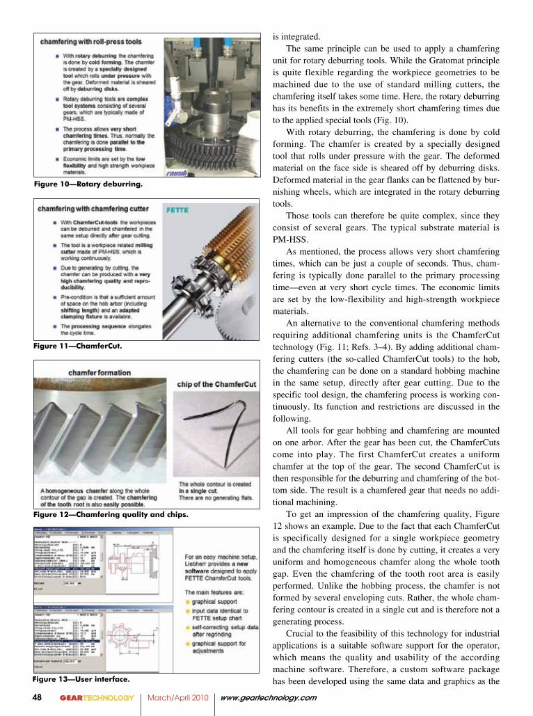
unit for rotary deburring tools. While the Gratomat principle is quite flexible regarding the workpiece geometries to be machined due to the use of standard milling cutters, the chamfering itself takes some time. Here, the rotary deburring has its benefits in the extremely short chamfering times due to the applied special tools (Fig. 10).
With rotary deburring, the chamfering is done by cold forming. The chamfer is created by a specially designed tool that rolls under pressure with the gear. The deformed material on the face side is sheared off by deburring disks. Deformed material in the gear flanks can be flattened by bur-nishing wheels, which are integrated in the rotary deburring tools.
Those tools can therefore be quite complex, since they consist of several gears. The typical substrate material is PM-HSS.
As mentioned, the process allows very short chamfering times, which can be just a couple of seconds. Thus, cham-fering is typically done parallel to the primary processing time—even at very short cycle times. The economic limits are set by the low-flexibility and high-strength workpiece materials.
An alternative to the conventional chamfering methods requiring additional chamfering units is the ChamferCut technology (Fig. 11; Refs. 3–4). By adding additional cham-fering cutters (the so-called ChamferCut tools) to the hob, the chamfering can be done on a standard hobbing machine in the same setup, directly after gear cutting. Due to the specific tool design, the chamfering process is working con-tinuously. Its function and restrictions are discussed in the following.
All tools for gear hobbing and chamfering are mounted on one arbor. After the gear has been cut, the ChamferCuts come into play. The first ChamferCut creates a uniform chamfer at the top of the gear. The second ChamferCut is then responsible for the deburring and chamfering of the bot-tom side. The result is a chamfered gear that needs no addi-tional machining.
To get an impression of the chamfering quality, Figure 12 shows an example. Due to the fact that each ChamferCut is specifically designed for a single workpiece geometry and the chamfering itself is done by cutting, it creates a very uniform and homogeneous chamfer along the whole tooth gap. Even the chamfering of the tooth root area is easily performed. Unlike the hobbing process, the chamfer is not formed by several enveloping cuts. Rather, the whole cham-fering contour is created in a single cut and is therefore not a generating process.
Crucial to the feasibility of this technology for industrial applications is a suitable software support for the operator, which means the quality and usability of the according machine software. Therefore, a custom software package has been developed using the same data and graphics as the
Figure 11—ChamferCut.
Figure 12—Chamfering quality and chips.
Figure 13—User interface.
Figure 10—Rotary deburring.
www.geartechnology.com March/April 2010 GEARTECHNOLOGY 49
setup sheets provided by the tool supplier to simplify the programming and adjustments (Fig. 13). Afterward, the soft-ware calculates and dictates the necessary axis movements.
When a tool is worn out, it can be easily re-sharpened on the rake face—identical to hob sharpening. The neces-sary adjustment of the setup data after re-sharpening of the ChamferCuts is done by the software, based on the actual outside diameter.
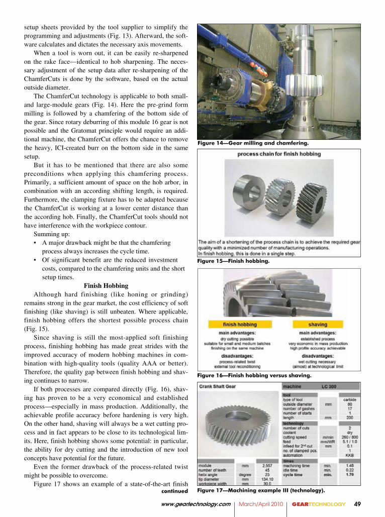
The ChamferCut technology is applicable to both small- and large-module gears (Fig. 14). Here the pre-grind form milling is followed by a chamfering of the bottom side of the gear. Since rotary deburring of this module 16 gear is not possible and the Gratomat principle would require an addi-tional machine, the ChamferCut offers the chance to remove the heavy, ICI-created burr on the bottom side in the same setup.
But it has to be mentioned that there are also some preconditions when applying this chamfering process. Primarily, a sufficient amount of space on the hob arbor, in combination with an according shifting length, is required. Furthermore, the clamping fixture has to be adapted because the ChamferCut is working at a lower center distance than the according hob. Finally, the ChamferCut tools should not have interference with the workpiece contour.
Summing up:• Amajordrawbackmightbethatthechamfering process always increases the cycle time.• Of significant benefit are the reduced investment
costs, compared to the chamfering units and the short setup times.
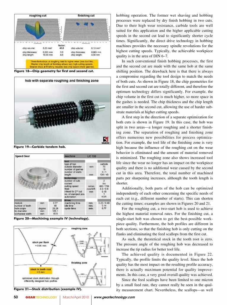
Finish HobbingAlthough hard finishing (like honing or grinding)
remains strong in the gear market, the cost efficiency of soft finishing (like shaving) is still unbeaten. Where applicable, finish hobbing offers the shortest possible process chain (Fig. 15).
Since shaving is still the most-applied soft finishing process, finishing hobbing has made great strides with the improved accuracy of modern hobbing machines in com-bination with high-quality tools (quality AAA or better). Therefore, the quality gap between finish hobbing and shav-ing continues to narrow.
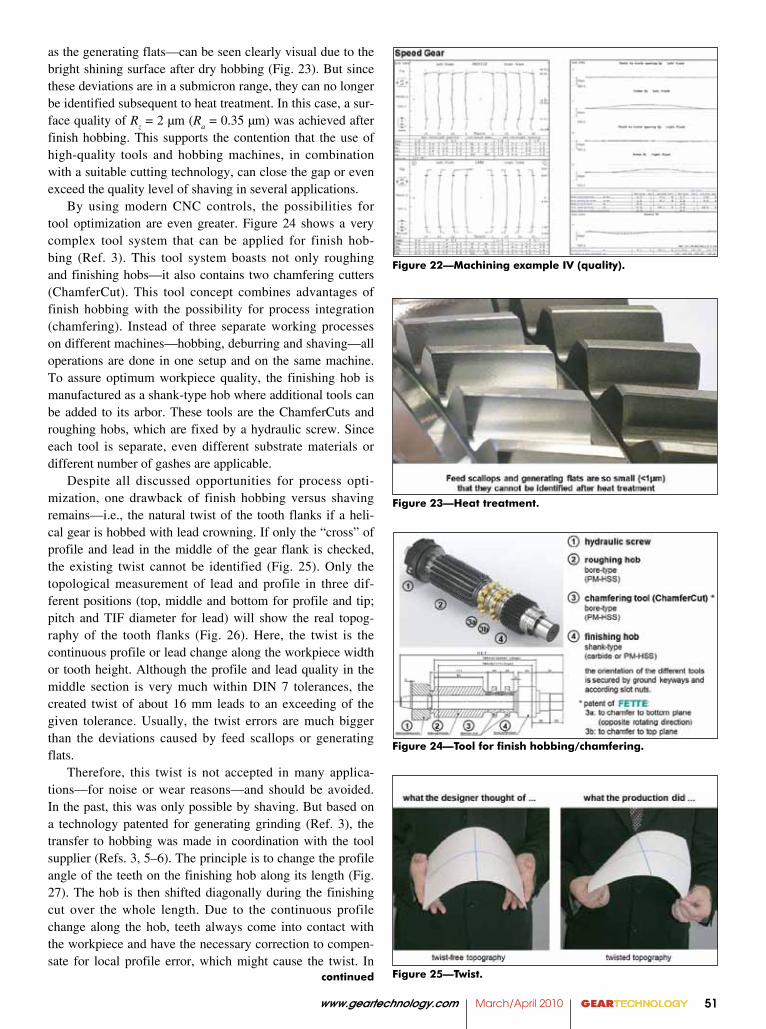
If both processes are compared directly (Fig. 16), shav-ing has proven to be a very economical and established process—especially in mass production. Additionally, the achievable profile accuracy before hardening is very high. On the other hand, shaving will always be a wet cutting pro-cess and in fact appears to be close to its technological lim-its. Here, finish hobbing shows some potential: in particular, the ability for dry cutting and the introduction of new tool concepts have potential for the future.
Even the former drawback of the process-related twist might be possible to overcome.
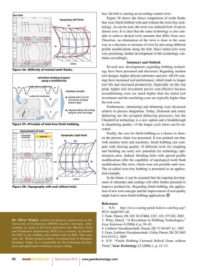
Figure 17 shows an example of a state-of-the-art finish
Figure 15—Finish hobbing.
Figure 16—Finish hobbing versus shaving.
Figure 17—Machining example III (technology).continued
Figure 14—Gear milling and chamfering.
GEARTECHNOLOGY March/April 2010 www.geartechnology.com50
hobbing operation. The former wet shaving and hobbing processes were replaced by dry finish hobbing in two cuts. Due to their high wear resistance, carbide tools are well suited for this application and the higher applicable cutting speeds in the second cut lead to significantly shorter cycle times. Significantly, the direct drive technology in hobbing machines provides the necessary spindle revolutions for the highest cutting speeds. Typically, the achievable workpiece quality is in the area of DIN 6–7.
In such conventional finish hobbing processes, the first and the second cut are made with the same hob at the same shifting position. The drawback here is that there is always a compromise regarding the tool design to match the needs of both cuts. As shown in Figure 18, the chip geometries for the first and second cut are totally different, and therefore the optimum technology differs significantly. For example, the chip volume in the first cut is much higher, so more space in the gashes is needed. The chip thickness and the chip length are smaller in the second cut, allowing the use of harder sub-strate materials at higher cutting speeds.
A first step in the direction of a separate optimization for both cuts is shown in Figure 19. In this case, the hob was split in two areas—a longer roughing and a shorter finish-ing zone. The separation of roughing and finishing zone offers numerous new possibilities for process optimiza-tion. For example, the tool life of the finishing zone is very high because the influence of the roughing cut on the wear behavior is eliminated and the amount of material removed is minimized. The roughing zone also shows increased tool life since the wear no longer has an impact on the workpiece quality and there is no additional wear caused by the second cut in this area. Therefore, the total number of machined parts per sharpening increases, although the tooth length is shorter.
Additionally, both parts of the hob can be optimized independently of each other concerning the specific needs of each cut (e.g., different number of starts). This can shorten the cutting times; examples are shown in Figures 20 and 21.
For the roughing cut, a two-start hob is used to achieve the highest material removal rates. For the finishing cut, a single-start hob was chosen to get the best-possible work-piece quality. Furthermore, the hob profiles are different in both sections, so that the finishing hob is only cutting on the flanks and eliminating the feed scallops from the first cut.
As such, the theoretical stock in the tooth root is zero. The pressure angle of the roughing hob was decreased to increase the tip radius for better tool life.
The achieved quality is documented in Figure 22. Typically, the profile limits the quality level. Since the hob quality has the most impact on the resulting profile accuracy, there is actually maximum potential for quality improve-ments. In this case, a very good overall quality was achieved.
Since the feed scallops have been limited to one micron by a small feed rate, they cannot really be seen in the qual-ity measurement chart. Nevertheless, the scallops—as well
Figure 19. Carbide tandem hob
Figure 20 Machining example IV (tec hnology)
Figure 21. Stock distribution (example IV)
Figure 19—Carbide tandem hob.
Figure 20—Machining example IV (technology).
Figure 21—Stock distribution (example IV).
Figure 18. Chip geometry for �rst and second cutFigure 18—Chip geometry for first and second cut.
www.geartechnology.com March/April 2010 GEARTECHNOLOGY 51
as the generating flats—can be seen clearly visual due to the bright shining surface after dry hobbing (Fig. 23). But since these deviations are in a submicron range, they can no longer be identified subsequent to heat treatment. In this case, a sur-face quality of R
z = 2 µm (R
a = 0.35 µm) was achieved after
finish hobbing. This supports the contention that the use of high-quality tools and hobbing machines, in combination with a suitable cutting technology, can close the gap or even exceed the quality level of shaving in several applications.
By using modern CNC controls, the possibilities for tool optimization are even greater. Figure 24 shows a very complex tool system that can be applied for finish hob-bing (Ref. 3). This tool system boasts not only roughing and finishing hobs—it also contains two chamfering cutters (ChamferCut). This tool concept combines advantages of finish hobbing with the possibility for process integration (chamfering). Instead of three separate working processes on different machines—hobbing, deburring and shaving—all operations are done in one setup and on the same machine. To assure optimum workpiece quality, the finishing hob is manufactured as a shank-type hob where additional tools can be added to its arbor. These tools are the ChamferCuts and roughing hobs, which are fixed by a hydraulic screw. Since each tool is separate, even different substrate materials or different number of gashes are applicable.
Despite all discussed opportunities for process opti-mization, one drawback of finish hobbing versus shaving remains—i.e., the natural twist of the tooth flanks if a heli-cal gear is hobbed with lead crowning. If only the “cross” of profile and lead in the middle of the gear flank is checked, the existing twist cannot be identified (Fig. 25). Only the topological measurement of lead and profile in three dif-ferent positions (top, middle and bottom for profile and tip; pitch and TIF diameter for lead) will show the real topog-raphy of the tooth flanks (Fig. 26). Here, the twist is the continuous profile or lead change along the workpiece width or tooth height. Although the profile and lead quality in the middle section is very much within DIN 7 tolerances, the created twist of about 16 mm leads to an exceeding of the given tolerance. Usually, the twist errors are much bigger than the deviations caused by feed scallops or generating flats.
Therefore, this twist is not accepted in many applica-tions—for noise or wear reasons—and should be avoided. In the past, this was only possible by shaving. But based on a technology patented for generating grinding (Ref. 3), the transfer to hobbing was made in coordination with the tool supplier (Refs. 3, 5–6). The principle is to change the profile angle of the teeth on the finishing hob along its length (Fig. 27). The hob is then shifted diagonally during the finishing cut over the whole length. Due to the continuous profile change along the hob, teeth always come into contact with the workpiece and have the necessary correction to compen-sate for local profile error, which might cause the twist. In
Figure 23. Heat treatment
Figure 24. Tool for �nish hobbing/chamfering
Figure 25. Twist
Figure 23—Heat treatment.
Figure 24—Tool for finish hobbing/chamfering.
Figure 25—Twist.continued
Figure 22. Machining example IV (quality)Figure 22—Machining example IV (quality).
GEARTECHNOLOGY March/April 2010 www.geartechnology.com52
fact, the hob is causing an according counter twist.Figure 28 shows the direct comparison of tooth flanks
that were finish hobbed with and without the twist-free tech-nology. As can be seen, the twist was reduced from 16 µm to almost zero. It is clear that the same technology is also suit-able to achieve desired twist amounts that differ from zero. Therefore, an elimination of the twist is done in the same way as a decrease or increase of twist by just using different profile modifications along the hob. Since initial tests were very promising, further development of this technology con-tinues accordingly.
Summary and OutlookSeveral new developments regarding hobbing technol-
ogy have been presented and discussed. Regarding modern tool designs, higher-alloyed substrates and new AlCrN coat-ings have increased tool performance, which leads to longer tool life and increased productivity. Especially on this last point, higher tool investment proves cost-effective because reconditioning costs are much higher than the initial tool investment and the machining costs are typically higher than the tool costs.
Furthermore, chamfering and deburring were discussed relative to process integration. Today, Gratomat and rotary deburring are the accepted deburring processes, but the ChamferCut technology is a new option and a breakthrough in chamfering quality—if the longer cycle times can be tol-erated.
Finally, the case for finish hobbing as a chance to short-en the process chain was presented. It was pointed out that, with modern tools and machines, finish hobbing can com-pete with shaving quality. If different tools for roughing and finishing are used, new potentials for technology opti-mization arise. Indeed, finishing hobs with special profile modifications offer the capability of topological tooth flank modifications like twist, which were not possible until now. The so-called twist-free hobbing is presented as an applica-tion example.
In the future, it can be assumed that the ongoing develop-ment of substrates and coatings will offer further potential to improve productivity. Regarding finish hobbing, the applica-tion of new tool concepts and the improvement of tool quality might lead to more finish hobbing applications.
References1. N.N. http://www.coating-guide.balzers.com/bcg.asp? WCI=Std&FID=60.2. Fette. Patent, DE 103 30 474B4, US7, 103, 973 B2, 2003.3. Witte, Darryl. “A Revolution in Hobbing Technologies,” Gear Solutions 4 (2006) 4, p. 38–43. 4. Liebherr-Verzahntechnik. Patent, DE 37 04 607 A1, 19875. Fette, Liebherr-Verzahntechnik. Utility Patent, DE 20 2005 014 619 U1, 20056. N.N. “Finish Hobbing Crowned Helical Gears without Twist,” Gear Technology 23 (2006) 1, p. 12–13.
Figure 27. Principle of twist--free �nish hobbing
Figure 28. Topography with and without twistFigure 28—Topography with and without twist.
Figure 27—Principle of twist-free finish hobbing.
Figure 26. Di�culty of twisted tooth �anksFigure 26—Difficulty of twisted tooth flanks.
Dr. Oliver Winkel studied mechanical engineering at the University of Technology (RWTH) Aachen, Germany. After working six years at the local Laboratory for Machine Tools and Production Engineering (WZL) as a scientist, he finished his PhD on dry hobbing with carbide hobs in 2004. That same year, Dr. Winkel joined Liebherr-Verzahntechnik in Kempten, Germany. Today, he is responsible for the technology develop-ment and application technology of gear cutting.