NEW DESIGN OF A TOP-FUEL DRAGSTER REAR WING - CiteSeer
159
TOP-FUEL DRAGSTER WING DESIGN USING CFD AND ITS INFLUENCE ON VEHICLE DYNAMIC PERFORMANCE By TONY MICHAEL BURATTI Bachelor of Science Oklahoma State University Stillwater, Oklahoma 1998 Submitted to the Faculty of the Graduate College of Oklahoma State University in partial fulfillment of the requirements for the Degree of MASTERS OF SCIENCE December, 2000
Transcript of NEW DESIGN OF A TOP-FUEL DRAGSTER REAR WING - CiteSeer

TOP-FUEL DRAGSTER WING DESIGN USING CFD
AND ITS INFLUENCE ON VEHICLE
DYNAMIC PERFORMANCE
By
TONY MICHAEL BURATTI
Bachelor of Science
Oklahoma State University
Stillwater, Oklahoma
1998
Submitted to the Faculty of the Graduate College of
Oklahoma State University in partial fulfillment of
the requirements for the Degree of
MASTERS OF SCIENCE December, 2000

ii
TOP-FUEL DRAGSTER WING DESIGN USING CFD
AND ITS INFLUENCE ON VEHICLE
DYNAMIC PERFORMANCE
Thesis Approved: ________________________________________________
Thesis Advisor ________________________________________________ ________________________________________________ ________________________________________________
Dean of the Graduate College

iii
ACKNOWLEDGEMENTS
I am deeply grateful to my parents, Richard M. and Joyce K. Buratti, for their love,
support and encouragement. They have instilled in me the value of hard work and
dedication which has helped me to become who I am today. Special thanks goes to my
grandmother, Frances Henson, for her love and support that she has provided.
I also extend my appreciation to the faculty and staff of the Mechanical and
Aerospace Engineering department at Oklahoma State University who have adopted me
and encouraged me to be successful. I would also like to thank the other members of my
committee, Dr. David G. Lilley and Dr. Gary E. Young, for their suggestions and
comments throughout this research.
Mr. Brian Vermillion of Advanced Racing Composites has provided support
through his knowledge, information, and insight into the racing community. I appreciate
all his time and resources that he has provided in support of my research and education. I
would also like to thank Dr. Kajal K. Gupta of NASA Dryden Flight Resource Center for
his support and sponsorship.
Lastly, I wish to express my sincere appreciation to my graduate advisor, Dr.
Andrew S. Arena Jr., for his continual support and guidance throughout the last couple of
years. He has been inspirational through his teachings and will continue to serve as a
great mentor throughout my professional career.
iv
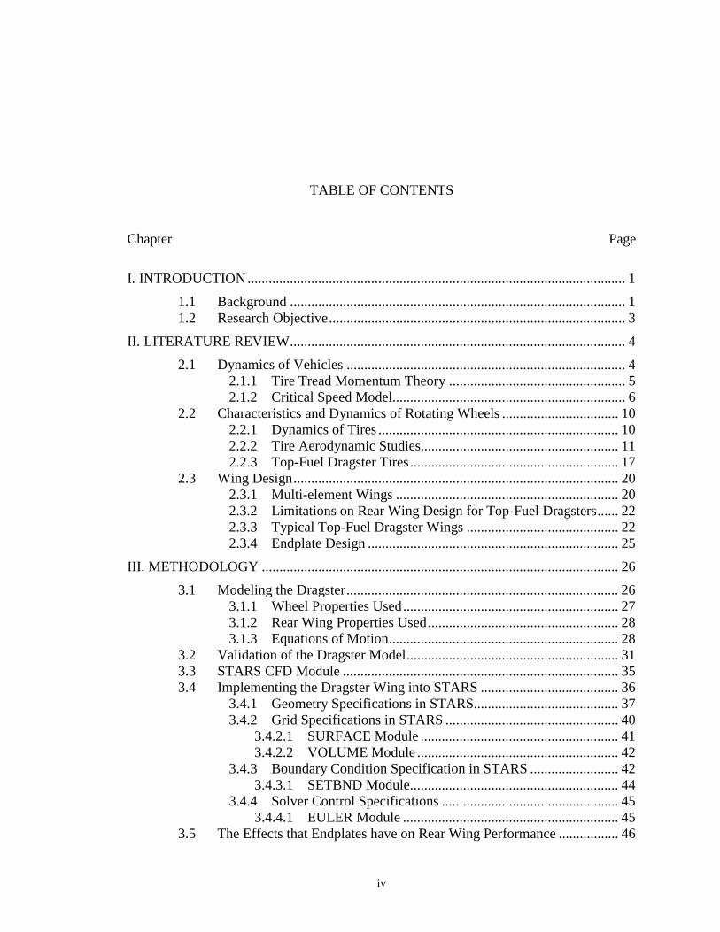
TABLE OF CONTENTS
Chapter Page
I. INTRODUCTION........................................................................................................... 1
1.1 Background ............................................................................................... 1 1.2 Research Objective.................................................................................... 3
II. LITERATURE REVIEW............................................................................................... 4
2.1 Dynamics of Vehicles ............................................................................... 4 2.1.1 Tire Tread Momentum Theory .................................................. 5 2.1.2 Critical Speed Model.................................................................. 6
2.2 Characteristics and Dynamics of Rotating Wheels ................................. 10 2.2.1 Dynamics of Tires .................................................................... 10 2.2.2 Tire Aerodynamic Studies........................................................ 11 2.2.3 Top-Fuel Dragster Tires........................................................... 17
2.3 Wing Design............................................................................................ 20 2.3.1 Multi-element Wings ............................................................... 20 2.3.2 Limitations on Rear Wing Design for Top-Fuel Dragsters...... 22 2.3.3 Typical Top-Fuel Dragster Wings ........................................... 22 2.3.4 Endplate Design ....................................................................... 25
III. METHODOLOGY ..................................................................................................... 26
3.1 Modeling the Dragster............................................................................. 26 3.1.1 Wheel Properties Used............................................................. 27 3.1.2 Rear Wing Properties Used...................................................... 28 3.1.3 Equations of Motion................................................................. 28
3.2 Validation of the Dragster Model............................................................ 31 3.3 STARS CFD Module .............................................................................. 35 3.4 Implementing the Dragster Wing into STARS ....................................... 36
3.4.1 Geometry Specifications in STARS......................................... 37 3.4.2 Grid Specifications in STARS ................................................. 40
3.4.2.1 SURFACE Module ........................................................ 41 3.4.2.2 VOLUME Module ......................................................... 42
3.4.3 Boundary Condition Specification in STARS ......................... 42 3.4.3.1 SETBND Module........................................................... 44
3.4.4 Solver Control Specifications .................................................. 45 3.4.4.1 EULER Module ............................................................. 45
3.5 The Effects that Endplates have on Rear Wing Performance ................. 46

v
Chapter Page
3.6 Box Wing Design .................................................................................... 47
IV. RESULTS................................................................................................................... 53
4.1 Effects of Endplate on Three-Element Dragster Wings.......................... 53 4.1.1 Pressure Contours .................................................................... 54 4.1.2 Cross-Flow Velocity ................................................................ 59 4.1.3 Velocity at the Tip of the Wing................................................ 69 4.1.4 Down Force to Drag Ratio ....................................................... 71 4.1.5 Mach Number and Coefficient of Pressure Distribution ......... 73
4.2 Gap Spacing Comparisons for a Three-Element Dragster Wing ............ 76 4.3 Angle of Attach Comparisons of Three-Element Dragster Wings.......... 78 4.4 World Record Performances ................................................................... 80 4.5 Using the Dragster Model to Analyze the Problem ................................ 80 4.6 Steady Results of Boxwing Design ......................................................... 89
4.6.1 Decalage Angle Comparisons .................................................. 89 4.6.1.1 Pressure Plots ................................................................. 90 4.6.1.2 Mach Plots ..................................................................... 93
4.6.2 Boxwing and Three-Element Wing Comparisons ................... 96 4.7 Dragster Performance Comparisons using the Dynamic Model ........... 100
4.7.1 Performance Data for Various Rear Wings ........................... 101 4.7.2 Performance Data for Various Input Power Curves .............. 103
V. CONCLUSIONS AND RECOMMENDATIONS .................................................... 107
5.1 Conclusions ........................................................................................... 107 5.1.1 Dynamic Dragster Model....................................................... 107 5.1.2 Endplate Effects on a Top-Fuel Dragster Rear Wing ............ 108 5.1.3 Boxwing Design..................................................................... 108
5.2 Recommendations ................................................................................. 109 5.2.1 Dynamic Dragster Model....................................................... 109 5.2.2 Endplate Design Improvements ............................................. 110 5.2.3 Boxwing Design..................................................................... 111 5.2.4 Stability of the Dragster ......................................................... 111
BIBLIOGRAPHY........................................................................................................... 112
APPENDIX A-1.............................................................................................................. 115 STARS-CFD Geometry Data File (fin.sur)...................................................... 115
APPENDIX A-2.............................................................................................................. 127
STARS-CFD Background Mesh Data File (fin.bac)........................................ 127
APPENDIX A-3.............................................................................................................. 129
STARS-CFD Boundary Conditions Data File (fin.bco)................................... 129
APPENDIX A-4.............................................................................................................. 130
vi
Chapter Page
STARS-CFD Parameter Control File (fin.cons)............................................... 130
APPENDIX B-1.............................................................................................................. 131
STARS-CFD Geometry Data File (boxwing.sur) ............................................ 131
APPENDIX B-2.............................................................................................................. 139
STARS-CFD Background Mesh Data File (boxwing.bac) .............................. 139
APPENDIX B-3.............................................................................................................. 141
STARS-CFD Boundary Conditions Data File (boxwing.bco) ......................... 141
APPENDIX B-4.............................................................................................................. 142
STARS-CFD Parameter Control File (boxwing.cons) ..................................... 142
APPENDIX C-1.............................................................................................................. 143
Selig 1223 Airfoil Coordinate Data.................................................................. 143
VITA............................................................................................................................... 145

vii
LIST OF TABLES
Table Page 3-1: Lift and Drag Coefficients for the Tires from Cogotti's Research ........................... 27
3-2: Surface Region Flags................................................................................................ 43
3-3: Curve Segment Flags................................................................................................ 43
4-1: Down Force and Drag for the Three Test Cases Analyzed ...................................... 72
4-2: Increase of Lift to Drag Ratio for the Three Test Cases Analyzed .......................... 73
4-3: Lift and Drag Coefficients for the Dragster Model .................................................. 82

viii
LIST OF FIGURES
Figure Page 1-1: Schematic of a top-fuel dragster................................................................................. 1
2-1: Drag Tire Schematic................................................................................................... 5
2-2: Schematic of an AA/FD Dragster with Forces........................................................... 8
2-3: Schematic of the Contact Patch................................................................................ 11
2-4: Schematic of Magnus Effects ................................................................................... 13
2-5: Experimental Study of Flow Past a Stationary and Rotating Wheel........................ 14
2-6: Pressure Distribution Around the Wheels of a Vehicle............................................ 14
2-7: Reynolds Number Effects on the Coefficient of Drag ............................................. 15
2-8: Flow Pattern Around a Smooth Cylinder at Various Re Number ............................ 16
2-9: Static View of a Top-Fuel Dragster Tire.................................................................. 17
2-10: Tire Expansion on Top-Fuel Dragster Burnout...................................................... 18
2-11: Top-Fuel Dragster Tire at the Start of a Run.......................................................... 19
2-12: Effects of Multiple Elements on the Coefficient of Lift......................................... 21
2-13: Endplate Size Dimensions...................................................................................... 24
3-1: Dragster Run Schematic Showing Two Areas ......................................................... 29
3-2: Validation of Position vs Time for a Top-Fuel Dragster (1/4 Mile) ........................ 32
3-3: Validation of Speed vs Time for a Top-Fuel Dragster (1/4 Mile)............................ 33
3-4: Validation of Acceleration vs Time for a Top-Fuel Dragster (1/4 Mile) ................. 34

ix
Figure Page
3-5: Validation of Speed vs Position for a Top-Fuel Dragster (1/4 Mile) ....................... 35
3-6: Wing Geometry Specification .................................................................................. 38
3-7: Rendered View of a Half-Span model with a Style 3 Endplate ................................ 39
3-8: Half Model of Dragster Rear Wing Mesh Density................................................... 40
3-9: Three Different Endplate Geometry Analyzed......................................................... 46
3-10: Selig 1223 Airfoil ................................................................................................... 48
3-11: Effect of the Number of Elements on an F-1 Type Wing ...................................... 49
3-12: Decalage Angle ...................................................................................................... 50
3-13: Rendered View of half model Boxwing with a 12° Decalage Angle..................... 52
4-1: Pressure Contours of the Wing without an Endplate................................................. 54
4-2: Pressure Contour of Wing with Style 3 Endplate...................................................... 56
4-3: Pressure Contour of Wing with New Style Endplate ............................................... 57
4-4: Pressure Gradient for Style 3 Endplate ..................................................................... 58
4-5: Cross Flow Velocity Cuts Represented by Vertical Lines ....................................... 60
4-6: Cross-Flow Velocity 7 in. back from L.E. w/o an Endplate .................................... 61
4-7: Cross-Flow Velocity 14 in. back from L.E. w/o an Endplate ................................... 62
4-8: Cross-Flow Velocity 20 in. back from L.E. w/o an Endplate ................................... 63
4-9: Cross-Flow Velocity 7 in. back from L.E. with Style 3 Endplate............................. 64
4-10: Cross-Flow Velocity 14 in. back from L.E. with Style 3 Endplate......................... 65
4-11: Cross-Flow Velocity 20 in. back from L.E. with Style 3 Endplate......................... 66
4-12: Cross-Flow Velocity 7 in. back from L.E. with New Endplate .............................. 67
4-13: Cross-Flow Velocity 14 in. back from L.E. with New Endplate ............................ 68

x
Figure Page
4-14: Cross-Flow Velocity 20 in. back from L.E. with New Endplate ............................ 68
4-15: Velocity at the Wingtip without an Endplate .......................................................... 69
4-16: Velocity just inside Style 3 Endplate....................................................................... 70
4-17: Velocity just inside New Endplate .......................................................................... 71
4-18: Pressure Distribution at the Tip of the Wing for Three Configurations.................. 74
4-19: Mach Distribution at the Tip of the Wing for the Three Configurations ................ 75
4-20: Velocity Profile of Wing with Original Gap Spacing ............................................ 76
4-21: Velocity Profile of Wing with Modified Gap Spacing........................................... 77
4-22: Pressure Plots for Angle of Attack Comparisons ................................................... 79
4-23: Input Power Curve and Acceleration Power Curve versus Time........................... 81
4-24: Power Curves along with Drag Power versus Time............................................... 83
4-25: Elapsed Time and Speed Data for Varying Drag Coefficient ................................ 84
4-26: Elapsed Time and Critical Speed Data for Varying Drag Coefficient ................... 85
4-27: Elapsed Time and Speed Data for Varying Lift Coefficient .................................. 86
4-28: Elapsed Time and Critical Speed Data for Varying Lift Coefficient ..................... 88
4-29: Pressure Plot for Boxwing at 0 Degree Decalage Angle........................................ 91
4-30: Pressure Plot for Boxwing at 8 Degree Decalage Angle........................................ 92
4-31: Pressure Plot for Boxwing at 12 Degree Decalage Angle...................................... 93
4-32: Mach Number Plot for Boxwing with 0 Degree Decalage Angle.......................... 94
4-33: Mach Numbar Plot for Boxwing at 8 Degree Declage Angle................................ 95
4-34: Mach Number Plot for Boxwing at 12 Degree Decalage Angle ............................ 96
4-35: Coefficient of Lift vs Angle of Attack ................................................................... 97

xi
Figure Page
4-36: Coefficient of Drag vs Angle of Attack ................................................................. 98
4-37: Coefficient of Drag vs Coefficient of Lift .............................................................. 99
4-38: Coefficient of Lift to Drag vs Coefficient of Lift................................................. 100
4-39: Elapsed Time and Speed Data with Different Wing Configurations ................... 102
4-40: Elapsed Time and Speed Data with Different Wing Configurations ................... 103
4-41: Model Power Input Curves to look at Horsepower Effects.................................. 104
4-42: Power Curve Input Effects on Elapsed Time and Top Speed .............................. 105

xii
NOMENCLATURE
CFD Computational Fluid Dynamics
NHRA National Hot Rod Association
A Aerodynamic reference area-projected frontal area of the vehicle
AR Aspect Ratio
CD Coefficient of drag
CL Coefficient of lift
Dfree Free diameter of the tire, unrestrained, inches
Fv Vertical tread force, lbf, impact momentum
L.E. Leading Edge
Mgrd Mass of tread, glbm , gW
grdM•
Mass rate of tread, sec⋅glbm
Ni Rear axle input speed, RPM
Nr Real axle speed, RPM, 2.3iN
Ρ Specific effective power
Re Reynolds number
RPM Revolutions per minute
S Wing area
SR Slip Ratio

xiii
a Distance to vehicles cg from the front wheels
b Wing span
c Chord length of an airfoil
d Distance from the vehicle cg to vehicles center of pressure
g Acceleration due to gravity
h Height of endplate
m Mass of the vehicle
s Horizontal distance traveled
s& Longitudinal velocity
s&& Longitudinal acceleration
sL Aerodynamic radius, L
L
AC
msρ
21
=
Λ, ∆ Fraction of lift on driving wheels including weight transfer effect
γ Traction coefficient
η Vehicle driving efficiency
λ Fraction of weight on driving wheels including weight transfer effect
µ Coefficient of rolling resistance
ρ Air density

1
CHAPTER 1
1. INTRODUCTION
1.1 Background
The dynamics of a Top-Fuel Dragster Car, depicted in Figure 1-1, are quite
complicated to model and pose problems for many research areas of interest. The Top-
Fuel Dragster is the fastest of drag racing vehicles. It accelerates at almost 4 longitudinal
g's completing a quarter mile run in less than five seconds. It reaches over 100 mph in
less than a second and finishes the run with speeds in excess of 320 mph. They are
powered by a supercharged engine that puts out over 6000 horsepower and the massive
tires spin at almost 8000 rpm. For a single run these dragsters consume more than 5
gallons of nitro methane fuel. The vehicles weight is around 2150 pounds, including the
driver, giving it a phenomenal power to weight ratio that puts it in a class like no other.
Figure 1-1: Schematic of a top-fuel dragster

2
Lift and drag are very important factors for this type of racing event. Many
components are responsible for creating this lift and drag but only a couple greatly affect
the dragsters performance. These components include the body, rear wheel dynamics,
and the rear wing.
The performance of the enormous rear tires, 36.0" x 17.0"-16's, add to the
complexity of the problem. During the run the tires stretch and deform due to a large
engine torque of around 4500 ft-lbs as well as the rotational inertial of the tire tread.
Normal operating pressure is 4 psig to 5 psig creating a tire footprint of over 250 square
inches at the start of the run. The tire constantly changes in size and can expand adding
an additional 4.5 inches to the diameter during a run. The rotational inertia of the tire
delivers a down force to the car. On the other hand, the flow over the wheels has a great
affect on the performance of the car because it results in a positive lift at the rear axle.
The rear wing is used to increase the amount of down force to the rear tires.
Increasing this down force increases the normal force between the tire and track surface,
which theoretically should increase the potential to use the engine power to accelerate the
dragster. If there is little normal force then there is potential for the car to experience
wheel slip and thus not have traction to accelerate.
The reason every top fuel dragster team doesn't make a rear wing that has an
enormous amount of down force is the fact that when lift is generated so is drag. This
drag is referred to as induced drag and is a function of the square of the velocity. This
increase in drag therefore takes more horsepower away from the acceleration horsepower
and results in a reduced maximum speed that can be achieved during the run. The

3
question is therefore how much down force is needed and at what time during the run is
the maximum amount of down force critical?
1.2 Research Objective
The emphasis of the present work is two fold. First is to develop an accurate
dynamic model for a quarter mile run of a top-fuel dragster. The model will be as
complete as possible accounting for the significant forces encountered on the vehicle.
The performance of the vehicle will be determined by the elapsed time and final speed.
The second portion of this work will be to study the effects that the aerodynamic
characteristics of a dragster and rear wing have on the performance of the dragster using
the model. From this data an alternative wing will be designed and analyzed. This data
will be entered into the model and compared to the current style of wings being used.
Most emphasis has gone into improving the rear wing characteristics but this will
not necessarily improve the performance of the dragster. The dynamic solver will be
used to determine if the new wing will improve the performance of the overall vehicle.
Therefore the focus will be in improving the performance of the car and not just focus on
improving the rear wing characteristics. A computational fluid dynamic (CFD) solver
will be used to analyze the wing characteristics and this information will be used in the
dynamic dragster model.

4
CHAPTER 2
2. LITERATURE REVIEW
This literature review covers several aspects of a dragster. First two dynamic
models will be discussed in detail and one will be modified and used for the current
research. Second the dynamics of the tires will be discussed to find out more about
modeling the tire dynamically and all the modeling problems that it might pose. The
other part of the tire research review will be on the aerodynamics of the tires since they
are large and rotate at high rpm. To end the chapter other aerodynamic studies will be
done for different wing designs talking about the general style of dragster wing used now
and the rules limiting the wings.
2.1 Dynamics of Vehicles
It is good to first look at the interaction between the vehicles aerodynamic
characteristics and wheel dynamics and see how they affect the overall vehicle
performance. Better and improved vehicle performance is what is truly desired and not
just the improvement of the components. Granted the improvements in components can
lead to better vehicle performance but how much and at what time during the run is the
question. The dynamics of the vehicles and how it is affected by the dynamics and

5
aerodynamics of the tires, the aerodynamic surfaces, and the aerodynamics of the
vehicle's body is what is looked at next.
2.1.1 Tire Tread Momentum Theory
Because Top-Fuel Dragsters accelerate at over 4 longitudinal g's for several seconds
this means that there is an effective tire friction factor of over 4 [Hallum, 1994]. This is
not possible and therefore Hallum offers a theory on his tread momentum principle.
Figure 2-1: Drag Tire Schematic
A schematic of a dragster tire is depicted in Figure 2-1 above. In this schematic the
tire contact angles, tread radius, tread sidewall twisting-straightening, and rotational
angles are all shown. Hallum states that the normal force applied to the ground under the
compressed area is about equal to the rate of change of vertical tread momentum at the
contact. This force, for one tire is given by equation ( 2-1).

6
θsin⋅⋅=
•
grdv VMF grd ( 2-1)
where
⋅
⋅=•
60RPMNMM r
grdgrd
⋅=
6012rfree ND
Vgrd
π
For this method there are three initial inputs into the system, which are start line
ride height (16.5 inches), rear axle RPM at initiation (0 RPM), ground velocity (0 ft/sec),
and acceleration due to rear static weight times the tire friction. The rear axle RPM and
ground velocity are from real data but it would seem that the ground velocity would be
something that should be calculated. The ride height was assumed and a constant friction
factor was used. The output is the tread horizontal momentum change and the
acceleration of the dragster.
This model did not give a whole lot of information as to how it works and proved
difficult to use when trying to implement. Therefore a different model was sought and
discovered that would prove more beneficial to the current research effort.
2.1.2 Critical Speed Model
A different model was proposed by [Hawks and Sayre, 1973] in which they study
the optimum straight-line performance of an automobile. They introduce the equations of
motion for a straight-line acceleration including both the aerodynamic lift and pitching
moment. Their results concluded that aerodynamic down force can improve performance

7
if the acceleration is limited by traction and that aerodynamic lift is beneficial when
power is the limiting factor.
Most of the trends in those days, when considering high-performance automobile
design, was to place emphasis on producing down force for the purpose of improving
cornering speeds. It was thought that these aerodynamic devices that were being used
degraded straight-line performance due to the drag but then it would be made up in the
cornering.
Hawks and Sayre found that, in certain circumstances, the straight-line performance
improved along with the cornering speed due to the introduction of these aerodynamic
down force generating devices. There studies looked at the performance of three vehicles
- an AA/FD Competition Fuel Dragster, a Ford Galaxie sedan, and the Lola T-140
Formula A car with several different aerodynamic devices.
It was found that below a certain speed, referred to as the critical speed, the vehicle
can spin its wheels. This force corresponds to the friction coefficient multiplied by the
normal force on the tires. When there are aerodynamic forces acting on the vehicle then
the force becomes a function of the vehicles speed squared. This increase in down force
comes with the penalty of increased drag due to the induced drag of the aerodynamic
surfaces as discussed previously. If the increase in driving force is greater than the
increase in drag then an improvement in performance will result.
Some of the assumptions that were made for this model include a rigid body in
rectilinear motion; the automobile is driven through one pair of wheels; acting on the
automobile are the driving force, the rolling resistance, the aerodynamic forces of lift and
drag, and the aerodynamic pitching moment; and there is an ideal transmission. It was

8
also assumed that below the critical speed, wheel spin is impending and the driving force
is dependent on the product of the friction coefficient and the normal force on the driving
wheel. Above this critical speed the driving force is proportional to the maximum power
and inversely proportional to the speed. The rolling resistance is assumed to be constant
for simplicity.
Figure 2-2: Schematic of an AA/FD Dragster with Forces [Hawks and Sayre, 1973]
When looking at the model in a more detailed manner the schematic of an AA/FD
Dragster and the forces acting upon it should be used and is depicted in Figure 2-2.
Using the vertical force equation and the moment equation to find the normal loads on
the tires, the equation of motion in the longitudinal direction can be derived. The
longitudinal acceleration for a speed that is less than the critical speed is shown in
equation ( 2-2 ).
[ ] ( )[ ] 2
21 sCC
mAgs LD &&& µγρµγλ −Λ+−−= ( 2-2 )
Equation ( 2-3 ) is the acceleration where the speed is greater than the critical speed.

9
[ ] 2
21 sCC
mAg
sms LD &
&&& µρµη +−−Ρ= ( 2-3 )
where γ
λh
a−
=1
γhda
−−=Λ
1
Since the critical speed is the speed at which the traction-limited driving force
equals the power-limited driving force it can be found by equating ( 2-2 ) and ( 2-3 ).
The resulting equation is a cubic equation in critical speed where the critical speed is the
smaller positive root of equation ( 2-4 ).
03 =
ΛΡ
+Λ
−γ
λm
sssgs LL && ( 2-4 )
where sL is the aerodynamic radius and is given by
L
L
AC
msρ
21
=
For the current research effort the critical speed model will be modified and used in
order to look at particular components of the dragster and how they affect the
performance. Actual parameters will be used when known but other parameters will be
estimated to develop a good model. This model will be validated using top-fuel dragster
data. Further research will be done to show patterns of the affects that changing the
aerodynamic characteristics have on the performance. The model will also be used to

10
look at a current wing used and see what types of changes can be made to it, if any, that
will help lower the elapsed time and increase top speed.
2.2 Characteristics and Dynamics of Rotating Wheels
The tire is one of the most important considerations of the racecar because it is the
linkage between the vehicle and the racing surface. There are many studies on the
dynamics of tires and the various things that affect the performance of the tire. The bulk
of the studies in this area have been for passenger cars but some of this can be used for
the current research. There will also be some discussion of the dynamics and
aerodynamics of various parts of the vehicle. After talking about passenger car tires and
the dynamics and aerodynamics, a section dealing with just top-fuel dragster tires will be
discussed.
2.2.1 Dynamics of Tires
The main bulk of the material for the dynamics of tires deals with lateral forces or
cornering forces. The research done in this field is for passenger tires and deals mainly
with trying to model a tire for passenger cars. For example several researchers look at
tire interaction with different surface terrain, how things differ when there is an uneven
vehicle, how the effects of braking and cornering affect traction, the effects of wheel
orientation, temperature and pressure variations, and various combinations of each.

11
Figure 2-3: Schematic of the Contact Patch
The concern for the current research is that for straight-line acceleration where it
deals with the longitudinal forces. When accelerating there are longitudinal forces
between the tire and the ground that arise in an area referred to as the tire footprint as can
be seen in Figure 2-3. The longitudinal forces have similarities to the lateral or cornering
forces inasmuch as there is an elastic distortion region, referred to as longitudinal
stretching, and a sliding or frictional region [Milliken and Milliken, 1995]. In addition to
these longitudinal forces there are other important forces that arise that come from the
aerodynamics of the tires.
2.2.2 Tire Aerodynamic Studies
Tire aerodynamics are not the main focus of this work but for modeling purposes it
is necessary to understand some of the characteristics of the tires when developing an

12
accurate dynamic model. Wheel aerodynamics is a topic that is not fully understood.
The information that is generated is based upon research done for the automotive
industry. A lot of time has been put into experimental wind tunnel setups where the
concern becomes ground interference. Once placed in the wind tunnel, a tire setup can
consist of several things:
1. The tire can be stationary (not allowed to rotate) varying the gap distance between the floor and the bottom of the tire.
2. It can be powered by a motor and vary the gap between the floor and the bottom of the tire.
3. The wind tunnel has a movable floor and the wheel is powered by a motor and placed on the moving floor.
All these tests in the wind tunnel are used to try to match existing tire aerodynamic
data. It might not be possible to have the ideal setup in the wind tunnel because they
might not have a moving floor, they might not be able to power the wheel, etc. The ideal
setup would be to have a wind tunnel vehicle that is able to rotate the wheels at their
appropriate speeds with zero ground clearance.
Studies have been done looking at the first setup where the tire is stationary and the
gap is varied. It was shown by using wool tufts around the wheels that for the stationary
wheels the difference between a sealed and unsealed ground clearance was almost
imperceptible [Stapleford and Carr, 1970]. It was stated that the boundary layer effect
restricted the flow of air under the wheels when the gap was opened. But when the
wheels were rotating, as in the second setup mentioned above, an additional airflow was
induced through these gaps and the flow pattern had changed considerably. The principal

13
effect of the rotation was an asymmetric pressure distribution causing a large negative lift
to be generated in accordance with the Magnus effect, which is discussed next.
For inviscid flow past a cylinder has a symmetric flow pattern and by symmetry the
lift and drag are zero. But for a rotating cylinder it will drag some of the fluid around
producing circulation. This in effect causes the flow to be asymmetric and the average
pressure is greater on the upper half of the cylinder than on the lower half of the cylinder
causing lift to be generated. This is known as the Magnus effect and is pictured in Figure
2-4. This figure was provided by [Munson, Young, and Okiishi, 1994].
In the figure, the first picture (a) is of a uniform upstream flow past a cylinder
without circulation. The second picture (b) is a free vortex at the center of the cylinder
while the last picture (c) is the combination of the free vortex and uniform flow past a
cylinder. This combination gives nonsymmetrical flow and thus produces lift.
Figure 2-4: Schematic of Magnus Effects
Further explanation is given by [Katz, 1995] where he talks about and shows the
difference in separation points for a rotating and non-rotating wheel in a wind tunnel. As
seen in Figure 2-5 the separation point on the rotating wheel (left) occurs much sooner

14
than the separation point on the stationary wheel (right). This figure was provided by
[Katz, 1995].
Figure 2-5: Experimental Study of Flow Past a Stationary and Rotating Wheel [Katz, 1995]
This early separation for the rotating wheel can be explained by studying Figure 2-6
which was provided by [Milliken and Milliken, 1995]. For the stationary wheels the
suction pressure is greater on the top of the wheels and thus causes a greater positive lift
upwards. When the rotation is introduced the separation point is further upstream
reducing the suction pressure and thus reducing this positive lift. The figure below is
from wind tunnel tests and the rotating wheel had an effective "zero" ground clearance
while the stationary wheel had a 0.25 inch ground clearance [Stapleford and Carr, 1969].
Figure 2-6: Pressure Distribution Around the Wheels of a Vehicle

15
Another thing that greatly affects the characteristics of tire performance is Reynolds
number. A little bit of information was provided by [Cogotti, 1983] about the effects of
Reynolds number. He also provides his tire data along with the corresponding critical
Reynolds number, which is based upon the turbulence and surface roughness. This
critical Reynolds number greatly affects the drag coefficient.
When looking at the Re number effects on a smooth cylinder, as seen in Figure 2-7,
the coefficient of drag is greatly affected. The figure below is not used for any data in
this work but it is merely to show how great Re number effects can be on an object
similar to the dragster tire. The figure was provided by [Munson, Young, Okiishi, 1994].
The calculated Re number for the top-fuel dragster tire at a top speed of 330 mph, based
upon its diameter, is 9.25x10⁶.
Figure 2-7: Reynolds Number Effects on the Coefficient of Drag [Munson, Young, Okiishi, 1994]

16
The letters in the previous figure correspond to flow patterns in Figure 2-8, below.
The wheel would see a similar flow pattern as it speeds up but in this case there is no
ground effects present and the cylinder is not spinning so the flow pattern is for visual
purposes only. This helps show the different flows that are encountered during the
dragsters run which make the analysis that much more difficult.
Figure 2-8: Flow Pattern Around a Smooth Cylinder at Various Re Number
One thing in common with all of these papers is that they all seem to come to the
conclusion that wheel aerodynamics are very difficult to measure experimentally and
their full interaction with the rest of the vehicle is still in a state of confusion. This was

17
mainly for passenger type tires without the added complications of the top-fuel dragster
tire where the high torque, low pressure, high speeds, and large tire deformations add to
the complexity of the problem.
2.2.3 Top-Fuel Dragster Tires
As mentioned before the top-fuel dragster has enormous rear tires, 36.0" x 17.0"-
16's as seen in Figure 2-9. The side walls of the 36-inch diameter tire are very flexible
and weighs around 47 pounds. The main tread of the tire comes in at a weight of around
30 pounds for its 17-inch width.
Figure 2-9: Static View of a Top-Fuel Dragster Tire
With a large engine torque of around 4500 ft-lbs coupled with the normal operating
tire pressure of 4 psig to 5 psig gives way to the large 4.5 inches of diameter expansion
that the tire sees. In Figure 2-10, there is a static picture before a burnout as well as a
picture of the same vehicle during the burnout. The tire has changed shape dramatically
both in the width and the diameter of the tire.

18
Figure 2-10: Tire Expansion on Top-Fuel Dragster Burnout
The tire footprint is over 250 square inches at the start of the run. With the wheels
spinning at almost 8000 rpm the rotational inertia of the tire can deliver an enormous
amount of down force to the car. When viewed in slow motion at the start of the run the
tremendous torque is applied and the tire is balled up at the front of the contact patch as
seen in Figure 2-11. The dragster squats and the weight transfers to the rear tires. The
wheel rim spins at a faster rate than the rest of the tire causing the sidewalls to wrinkle up
at the bottom. Once the tread reaches the rear part of the contact patch it speeds up to
catch up with the rest of the wheel rim. This momentum causes great forces that are
responsible for the incredible acceleration according to [Hallum, 1994].
19
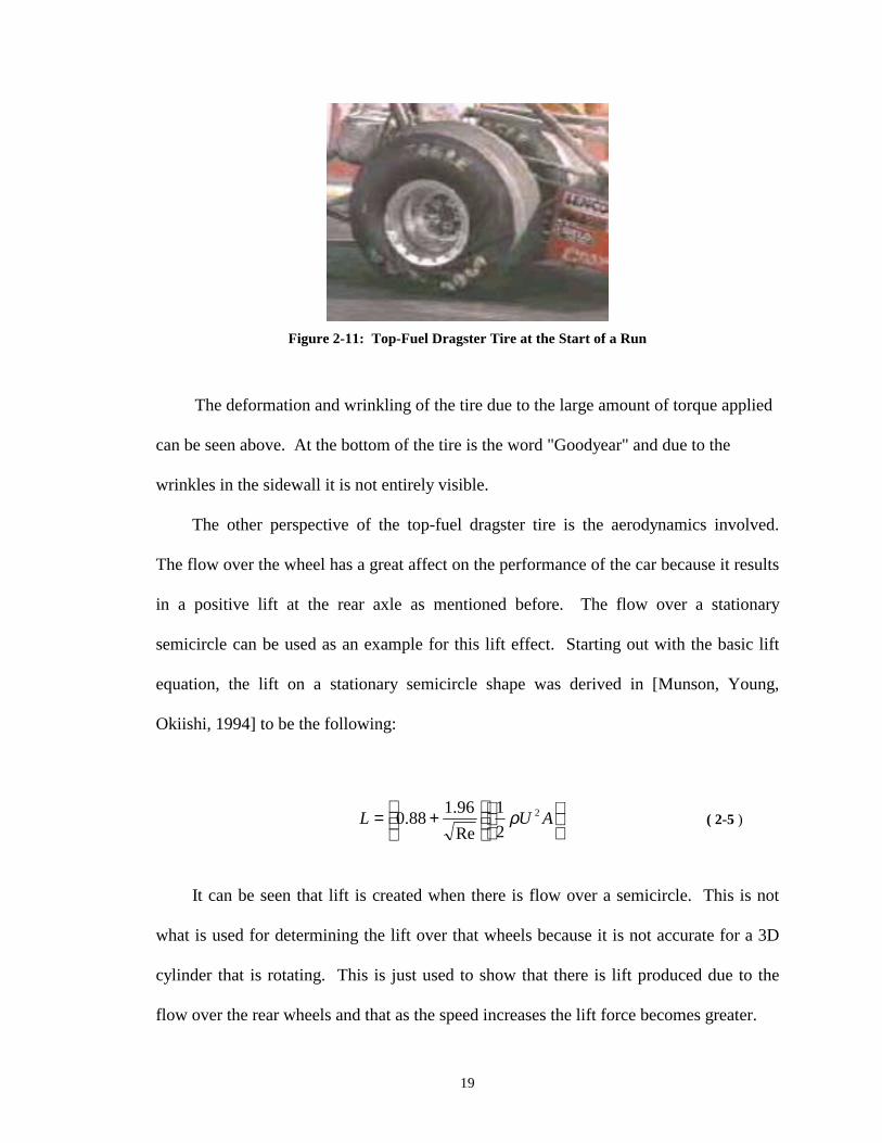
Figure 2-11: Top-Fuel Dragster Tire at the Start of a Run
The deformation and wrinkling of the tire due to the large amount of torque applied
can be seen above. At the bottom of the tire is the word "Goodyear" and due to the
wrinkles in the sidewall it is not entirely visible.
The other perspective of the top-fuel dragster tire is the aerodynamics involved.
The flow over the wheel has a great affect on the performance of the car because it results
in a positive lift at the rear axle as mentioned before. The flow over a stationary
semicircle can be used as an example for this lift effect. Starting out with the basic lift
equation, the lift on a stationary semicircle shape was derived in [Munson, Young,
Okiishi, 1994] to be the following:
+= AUL 2
21
Re96.188.0 ρ ( 2-5 )
It can be seen that lift is created when there is flow over a semicircle. This is not
what is used for determining the lift over that wheels because it is not accurate for a 3D
cylinder that is rotating. This is just used to show that there is lift produced due to the
flow over the rear wheels and that as the speed increases the lift force becomes greater.

20
2.3 Wing Design
To keep these rear wheels in contact with the race surface aerodynamic surfaces are
used. There are two wings, the front and rear, on a top-fuel dragster car, which help the
performance in different ways. The primary purpose of the front wing is to keep the
vehicle from pitching up in the front and flipping over. Since the rear wing is mounted as
far aft as possible, there is a tendency for the front wheels to be lifted off of the track.
The counteracting balance comes from the negative lift produced by the front wing. The
required down force of the front wing is enough to keep the overall vehicle from flipping
over and provide enough pressure to the front wheels so that the driver has control over
the steering. The rear wing is more of the focus of this research.
2.3.1 Multi-element Wings
Sometimes when designing a wing it is desired to produce more down force.
Different methods used to obtain more down force are increasing the wing area, increase
the camber of the airfoil, and delay flow separation by slotted flap design or multi-
elements [Katz, 1995]. Since the wing area is fixed by the NHRA regulations, which will
be presented in detail in the next section, then the alternative is to use wings with multi-
elements.
Experimental studies on multi-element wings proved that larger lift coefficients
could be obtained. These experiments were first performed by Handley Page and the
results can be seen in Figure 2-12. This figure was provided by [Smith, 1975]. The

21
airfoil was a RAF 19 and they are separated by a number of slots. The numbers represent
the number of slots with a two-element airfoil having one slot, a three-element airfoil
having two slots, and so on. It can be seen that higher angles of attacks can be reached
and the coefficient of lift can reach as much as 4.
Figure 2-12: Effects of Multiple Elements on the Coefficient of Lift [Smith, 1975]

22
These slots allow high pressure air from the bottom side of the wing to exit through
the gap and flow over the top of the next element. This will tend to reduce the separation
while increasing lift and reducing drag.
2.3.2 Limitations on Rear Wing Design for Top-Fuel Dragsters
Since Top-Fuel Dragsters compete in sanctioned races, the governing body or the
National Hot Rod Association (NHRA), has instilled rules and regulations that must be
met. According to the NHRA 2000 Rulebook the rear wing is limited in type, size, and
position. The wing must be locked into place as to prevent adjustment of any part of the
wing during the run. The combined total area of all wings, canards, and airfoils mounted
behind the front spindle can be no more than 1500 square inches. The position of the rear
wing is limited by it height and aft placement. The trailing edge may not extend more
than 50 inches behind the centerline of the rear axle and the height of any part of the wing
may not exceed 90 inches measured vertically from the ground.
2.3.3 Typical Top-Fuel Dragster Wings
A typical rear wing design for a top-fuel dragster is a three-element wing with
endplates. The material has been aluminum but with the advances in composites most
are made of carbon fiber and Kevlar for the outer skins as well as the endplates.
Typical rear wings have an aspect ratio of around 2.4. The aspect ratio of a wing is
defined by equation ( 2-6 ) as being the ratio of the span of the wing squared to the area
of the wing.

23
SbAR
2
= ( 2-6 )
The higher the aspect ratio the better the performance of the wing. When a wing is
generating lift, it has a reduced pressure on the upper surface and an increased pressure
on the lower surface. The air wants to get to the lower pressure and thus flows over the
tip of the wing. This escaping air reduces the pressure difference near the tip of the wing
and thus reduces the lift near the tip. For a wing with the same area this effect is greater
for lower aspect ratio wings because the span of the wing is less than that of a high aspect
ratio wing. For the high aspect ratio wing the pressure difference at the tip is less
significant because it affects a smaller portion of the overall wing. This is why the higher
the aspect ratio the better the performance characteristics.
To increase this aspect ratio means increasing the span of the wing or decrease the
area of the wing. Increasing the span of the wing can only be done to a certain limit
constrained by the width of the dragster. It can be extended past the width of the vehicle
but during the race if any part of the dragster crosses the middle dividing line on the drag
strip then that dragster is disqualified. This is the main reason that the span of the wing is
kept at or below the width of the vehicle.
The effects of increasing this wing span were presented by [Winn, Kohlman,
Kenner, 1999] which showed improvement as expected but increasing the span is not
desirable as discussed earlier. They show increasing the span of the wing by 3 feet. This
is great from an aerodynamic perspective but when it is looked at from the perspective of
the race team or the driver it would add one more complication to the race. The driver
would have to worry about staying that much further away from the center line.

24
In an attempt to increase the performance by decreasing this loss an addition to the
wing called an endplate can be used. The endplate, seen in Figure 2-13 and provided by
[Katz, 1995], maintains a pressure difference between the upper and lower portion of the
wing that not only improves the performance of the wing at the tip and thus improves the
overall wing performance. Therefore there is an effective aspect ratio calculation that can
be made that is presented by [Raymer, 1992] and is shown in equation ( 2-7 ).
⋅+⋅=
bhARAReffective 9.11 ( 2-7 )
Thus by increasing the height to span ratio of the endplate a greater effective aspect
ratio can be obtained. The effects of changing the endplate design will be discussed later
in another section.
Figure 2-13: Endplate Size Dimensions

25
2.3.4 Endplate Design
As previously mention the effects of the endplates have proven to provide a more
effective wing in the case of the low aspect ratio wing such as the rear wing of a dragster.
The endplates on a typical dragster has been shaped based upon a "coolness" factor
instead of on an aerodynamic performance factor. CFD analysis was performed on a
three-element top-fuel dragster wing to study the aerodynamics involved. After careful
analysis it was determined that due to the huge pressure difference between the top and
bottom of the wing the flow was spilling over the top of the endplate and would disrupt
the flow on the bottom surface of the wing. This reduced the amount of potential down
force that the wing could generate. After determining this, adjustments were made to
reduce this spillover effect and new endplates were designed and rerun in STARS. Vast
improvements were made in the down force to drag ratio.
Although this improvement to the wing design was beneficial to the wings down
force to drag ratio it has not been proven that the enormous amount of down force
generated is necessary to the overall vehicle performance. This is where the study of the
dynamics of the vehicle, which includes the aerodynamics, will be beneficial to the
understanding of the overall effect of the dragster rear wing. It is also the intent of the
author to show how much these improvements in wing design affects the performance of
the vehicle such as the elapsed time and top speed for a quarter mile run.

26
CHAPTER 3
3. METHODOLOGY
This chapter is broken down into several sections that include the methodology
behind the dragster model. The description of the STARS CFD code used and the
implementation of a dragster wing into STARS. Also the setup to determine how the
endplates effect the rear wing performance will be discussed followed by the
development of a new type of dragster wing.
3.1 Modeling the Dragster
Several approaches were explored when trying to come up with a good dragster
model. First the equations of motion for the dragster needed to be derived by studying all
the forces acting on the vehicle. These included all of the lift and drag properties of the
vehicle, the weight and weight transfer, the dimensions of certain parts of the dragster,
and the performance of the engine and overall drive train. The lift and drag properties
will be explored first building up to the full equations of motion.

27
3.1.1 Wheel Properties Used
The wheels were one of the more difficult components to get true data for because
of the dynamics of these types of tires as discussed earlier. Lift and drag are generated by
a number of different ways not just due to the flow around the tire but due to the rotation
of the tires as well. In the previous chapter the aerodynamics of a rotating object was
discussed. For the lift and drag characteristics of a rotating tire, research done by
[Cogotti, 1983] will be used. Wind tunnel tests were done with the tires in direct contact
with the balance and the wheel was powered.
Cd 0.579
Cl 0.18
Table 3-1: Lift and Drag Coefficients for the Tires from Cogotti's Research
Since the model was looking at general trends in aerodynamic effects on dragster
performance a complicated tire model was not sought after. The data found on modeling
tires was so detailed and was concerned with so many different aspects of the tires that it
was decided that a simple tire model will be sufficient. Sure the tire can be analyzed and
modeled in greater detail but the current research is concerned with finding general trends
for the purpose of analyzing the rear wing and not concerned with advanced tire models.

28
3.1.2 Rear Wing Properties Used
The rear wing had two different sources of drag - induced drag and area drag. The
first portion of drag, induced drag, is provided by the STARS code. This entails entering
the dimensions of the object into a computer and using CFD to determine the
aerodynamic properties of the object. STARS and implementing the wings into STARS
is discussed later in this chapter.
The second type of drag used is area drag. The area drag is estimated by breaking
the dragster wing into different components and estimating these different component
drags.
The lift component for the wing is determined using STARS. The wetted area of
the wing is provided by STARS and the plan form area of the wing is set by the NHRA
rules.
3.1.3 Equations of Motion
After all the parameters are determined the next step is to determine the equations
of motion for the dragster. The equations of motion are derived by summing the forces
on the dragster. There are two regions that determine which equation is going to be used
which can be seen in Figure 3-1. The first region is the traction limited acceleration
portion of the track. This is where the acceleration power is so great that the wheels
would slip if the throttle was held wide open. There is not enough down force to grip the
wheels to the ground therefore the driver must ease on the throttle until they reach a point

29
at which this is no longer a scenario where the wheels can spin. This point is called the
critical velocity of the vehicle.
Figure 3-1: Dragster Run Schematic Showing Two Areas
This critical velocity point is the transition between the traction limited acceleration
and the power limited acceleration. In the power limited acceleration region there is so
much down force that the power used to accelerate the vehicle is not large enough to spin
the wheels. In other words, the normal force from the wheels to the ground multiplied
by the friction factor of the tires is greater than the force generated by the torque from the
engine.
The two different equations of motion are shown below. The first equation of
motion, Equation ( 3-1), is the traction limited acceleration which is valid below the
critical velocity. After this critical velocity is reached the second equation of motion can
be utilized which is the power limited acceleration shown in Equation (3-2).
For
crvx <& [ ] 01 2 =−−
−Λ++ gxss
x rrL
rr
D
µγλµγ&&& ( 3-1)

30
For
crvx >& 01 2 =+
−+Ρ− gx
ssxmx rr
L
rr
D
µµ&
&&& (3-2)
where γ
λh
a−
=1
γhda
−−=Λ
1
The idea of this model is to use the lift and drag coefficient data along with the
other vehicle properties such as the effective input engine power and vehicle dimensions
to find the critical velocity of the vehicle. Since the critical speed is the speed at which
the traction-limited driving force equals the power-limited driving force it can be found
by equating ( 3-1) and. (3-2). The resulting equation is a cubic equation in critical speed
where the critical speed is the smaller positive root of equation ( 3-3 ).
03 =
ΛΡ
+Λ
−γ
λm
sssgs LL && ( 3-3 )
where sL is the aerodynamic radius and is given by
L
L
AC
msρ
21
=
After the critical velocity is found the corresponding position and time are
calculated using the acceleration from equation ( 3-1) and simple dynamics. From this
point the differential equation for velocity less than the critical velocity can be solved.

31
Using the critical velocity and position as inputs and the corresponding time as the
starting time the second differential equation (3-2) for velocity greater than critical
velocity can be solved.
Plotting can be done of position, velocity, and acceleration for the given vehicle
data. In the results section this model will be implemented using dragster characteristics
and this will be compared to position, velocity, and acceleration from and actual dragster
run.
Once the model is established and validated it can be used in a number of ways.
First of all trends can be found to see how aerodynamic characteristics will affect the
performance of a dragster. Once this is know the second approach will be to use if to
come up with a new wing design that will allow the performance of the dragster to
improve either by elapsed time, by top speed, or maybe both.
3.2 Validation of the Dragster Model
In order to validate the model it was necessary to match the position, velocity, and
acceleration data from an actual dragster run. Speed versus distance and position versus
time data was found [Winn and Kohlman, 1999] and used for the validation. In order to
get the speed versus time curves the position versus time data had to be differentiated.
Double differentiation of the position versus time data was used to compare the
acceleration data of the model.
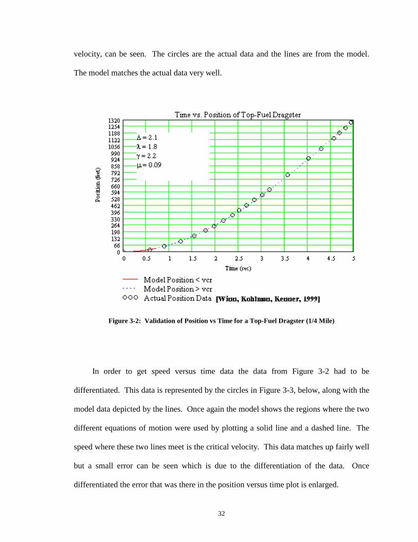
The first validation plot is position versus time which is shown below in Figure 3-2.
In this plot the two different regions of analysis, both below and above the critical
32
velocity, can be seen. The circles are the actual data and the lines are from the model.
The model matches the actual data very well.
Figure 3-2: Validation of Position vs Time for a Top-Fuel Dragster (1/4 Mile)
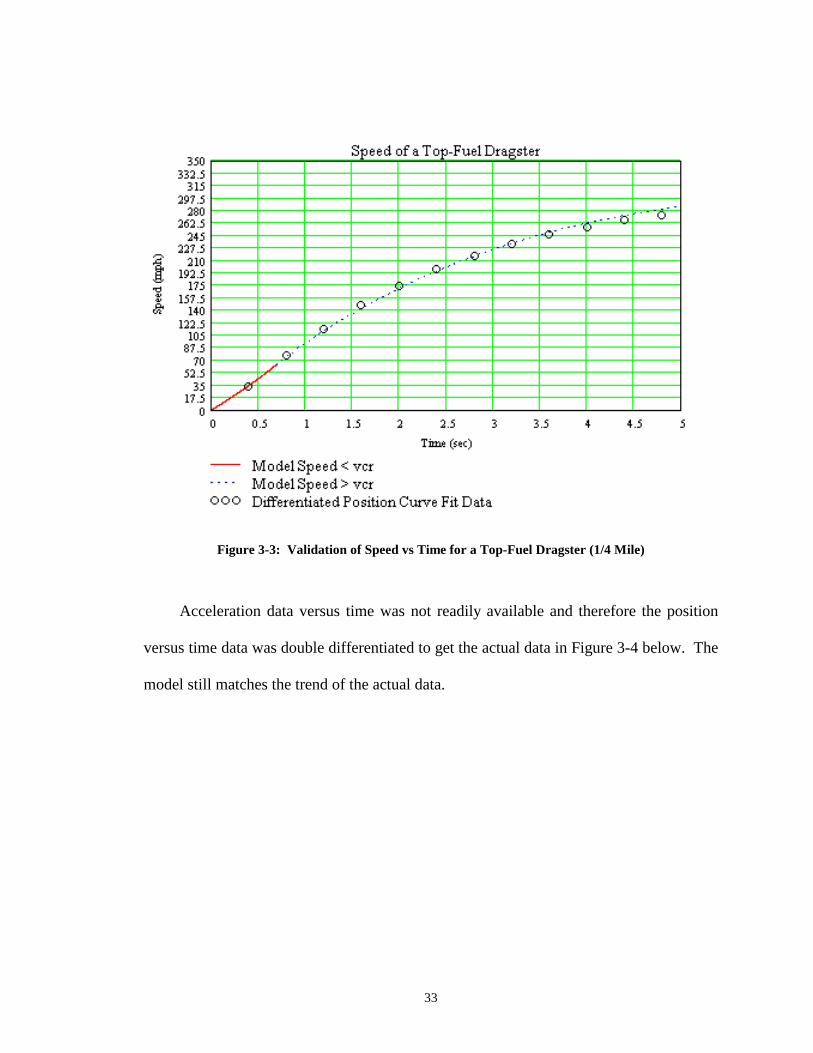
In order to get speed versus time data the data from Figure 3-2 had to be
differentiated. This data is represented by the circles in Figure 3-3, below, along with the
model data depicted by the lines. Once again the model shows the regions where the two
different equations of motion were used by plotting a solid line and a dashed line. The
speed where these two lines meet is the critical velocity. This data matches up fairly well
but a small error can be seen which is due to the differentiation of the data. Once
differentiated the error that was there in the position versus time plot is enlarged.
33
Figure 3-3: Validation of Speed vs Time for a Top-Fuel Dragster (1/4 Mile)
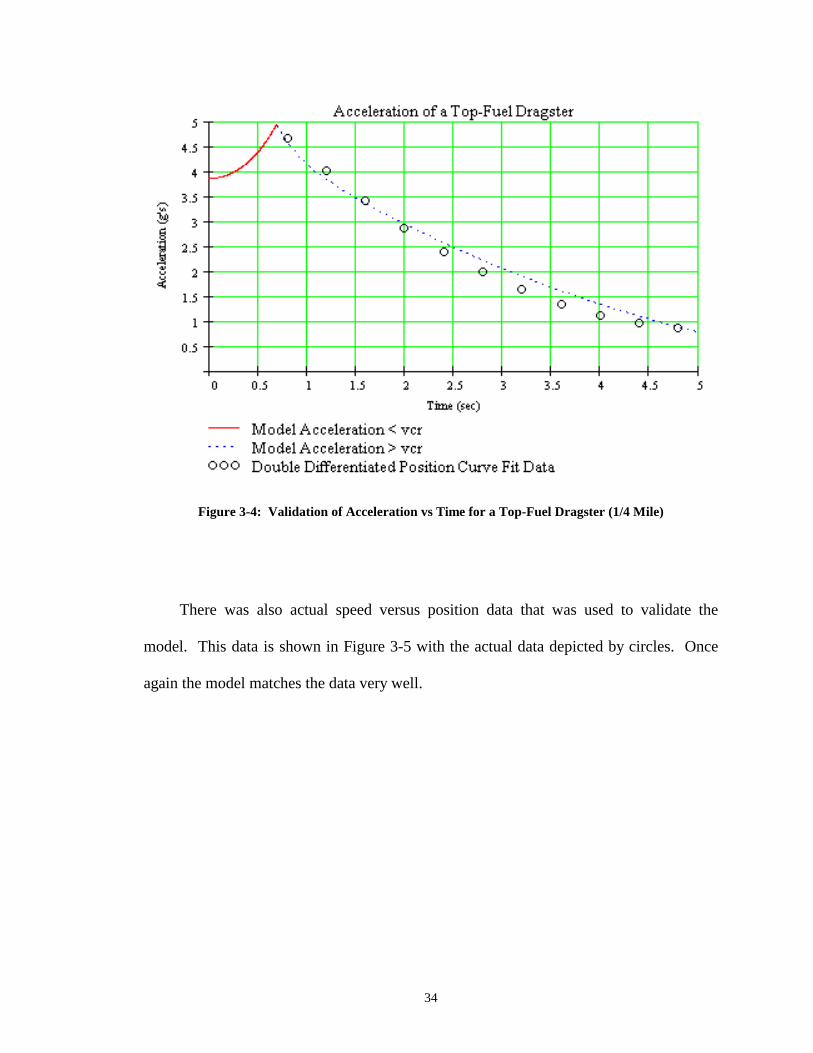
Acceleration data versus time was not readily available and therefore the position
versus time data was double differentiated to get the actual data in Figure 3-4 below. The
model still matches the trend of the actual data.
34
Figure 3-4: Validation of Acceleration vs Time for a Top-Fuel Dragster (1/4 Mile)
There was also actual speed versus position data that was used to validate the
model. This data is shown in Figure 3-5 with the actual data depicted by circles. Once
again the model matches the data very well.

35
Figure 3-5: Validation of Speed vs Position for a Top-Fuel Dragster (1/4 Mile)
3.3 STARS CFD Module
One of the research tools used for this project is portion of a set of codes developed
at NASA Dryden Flight Research Center known as STARS. STARS stands for
STructural Analysis RoutineS, which is a highly integrated computer program for
multidisciplinary analysis of flight vehicles including static and dynamic structural
analysis, CFD, heat transfer, and aeroservoelasticity [Gupta, 1997]. For the current
effort, only the CFD module of the code will be utilized for analyzing the aerodynamic
characteristics of the wings.

36
The CFD module is an Euler based code that applies finite element CFD on an
unstructured grid. The mesh generation uses the advancing front technique to generate
the unstructured mesh, which had been proven to be effective in complex structures.
When implementing the CFD module it is pertinent to follow a set of steps. This module
consists of the following four major parts and should be run in the order that they are
listed:
• SURFACE - generates a surface triangulation • VOLUME - generates a three-dimensional computational domain • SETBND - defines the boundary conditions in the domain • EULER - steady or unsteady Euler flow solver
The easiest way to explain these different modules is to implement an actual
problem into STARS step-by-step. The steps used and the data file structures and
contents will be discussed in more detail in the next section. The problem that is being
used is the rear dragster wing that has a style 3 endplate. The differences in the wings
and endplates will be discussed later.
3.4 Implementing the Dragster Wing into STARS
As mentioned before there are four main modules or steps to follow, in order,
before the user gets the solution. The first step in order to analyze the dragster wing in
STARS is to setup the geometry data into the format so that STARS can read it. After
the geometry is entered a mesh generation is enacted and a refinement in the density of
the grid is performed until a suitable mesh is found. The last step before running the flow

37
solver is to specify the boundary conditions for the geometry and flow domain. The
aforementioned modules are discussed in more detail in the following subsections.
3.4.1 Geometry Specifications in STARS
The geometry is made up of curves and surfaces that define the geometry of the
dragster wing and the geometry of the flow domain. The geometry data file is a
formatted data file that will be referred to as case.sur, were case can be any name that the
user specifies. The dragster rear wing geometry file can be found in Appendix A-1.
The lines are oriented in a specific direction, defined in the direction of the arrows
in Figure 3-6, according to the way STARS reads in the geometry. The lines are defined
by means of an ordered set of points. The curve component is a continuous cubic spline,
which is interpolated through these points. The model is a half span model with a
symmetry plane. Using this symmetry plane cuts down on the computational time of the
job without sacrificing the accuracy of the solution.

38
Figure 3-6: Wing Geometry Specification
It might be noticed that the numbering in Figure 3-6 starts out at three. The first
two numbered lines define the flow domain that surrounds the geometry. The flow
domain is a large hemisphere. There are ten chord lengths between the wing geometry
and the outer surface of the hemisphere. The flat side of the hemisphere is the symmetry
plane and is where the half span model of the rear dragster wing is attached.
After the curves are defined the next step in STARS is to specify the surfaces of the
geometry. This is done by specifying each line that makes up the surface in a specific
order. There are two possibilities that STARS will see depending on the order that the
lines are specified - either a surface or a whole in a surface. When defining the surface
the right hand rule must be used. The direction of the lines are important to this step and
when using the right hand rule the fingers curl in the direction of the specified lines and

39
the thumb has to point into the flow. If the thumb points into the geometry then the
surface was not specified correctly.
When this is completed the wing looks like Figure 3-7. For the dragster wing that
was analyzed, the largest and main element is based upon a set of data points. The chord
length of this element is 14.1 inches long. This main element is set at zero angle of
attack. The second element is an NACA 9400 type airfoil with a chord length of 5.25
inches. It is set at a 28-degree angle of attack with respect to the chord line of the main
element. The third and final element is an NACA 4300 type airfoil with a chord length of
5.25 inches. It is set at a 65-degree angle of attack with respect to the main element
chord line.
The configuration of the wing analyzed was 0°-28°-65°. The configuration, 0°-28°-
65°, refers to the angle of attack of each of the three individual elements. The wing was
adjustable to different configurations but this configuration was the one most commonly
used and therefore was the configuration that was used in the analysis.
Figure 3-7: Rendered View of a Half-Span model with a Style 3 Endplate
40
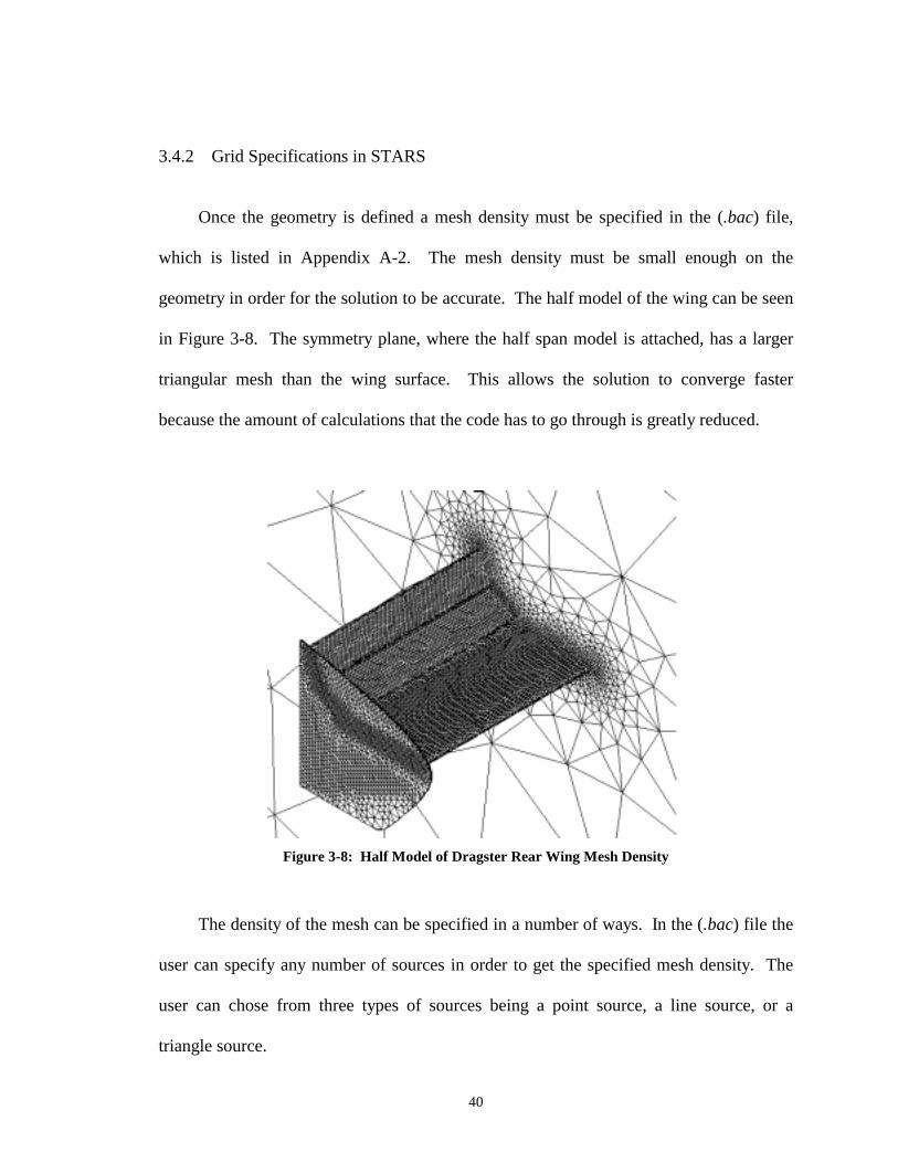
3.4.2 Grid Specifications in STARS
Once the geometry is defined a mesh density must be specified in the (.bac) file,
which is listed in Appendix A-2. The mesh density must be small enough on the
geometry in order for the solution to be accurate. The half model of the wing can be seen
in Figure 3-8. The symmetry plane, where the half span model is attached, has a larger
triangular mesh than the wing surface. This allows the solution to converge faster
because the amount of calculations that the code has to go through is greatly reduced.
Figure 3-8: Half Model of Dragster Rear Wing Mesh Density
The density of the mesh can be specified in a number of ways. In the (.bac) file the
user can specify any number of sources in order to get the specified mesh density. The
user can chose from three types of sources being a point source, a line source, or a
triangle source.

41
A point source allows for a sphere like mesh density that can change the size of
mesh to start out with, how large of a sphere, and how far out until the mesh size is
double of the original starting size. Point sources can be used on the front of an airplane
body, such as the nose of the X-29 experimental aircraft, in order to make the geometry
mesh tighter.
The line source differs from a point source in that it is cylinder like and there is a
specified length instead of a sphere. The line sources are typically used in the leading
and trailing edges of a wing because of the sharp transition in geometry.
The triangle source is a mesh density in the shape of a three dimensional triangle.
They can be used in a number of ways for a number of different situations. In the
dragster wing case two triangle sources are used per wing in a way as to make a rectangle
running thru the chord of the wing to refine the mesh on the surface of the wings. They
are also used on the endplates since the endplate is so thin it allowed for a refined mesh
so that the solution around the endplate is accurate.
3.4.2.1 SURFACE Module
After generating the geometry data file and the background mesh data file the first
step is to run the SURFACE module. The SURFACE module generates a couple of data
files. The first is a (.RST) file, where the .RST is just the suffix that is added to the
problem name, e.g. fin.RST or wing.RST. This file is an auxiliary file in which all of the
information about the generation processed is dumped. This allows the user to re-start
the SURFACE module if the program is stopped before completion.

42
The second file generated is a (.fro) file that stores the information about the
triangulation of the surface in the three-dimensional and the parametric space. This file is
used for input to the VOLUME and SETBND modules, which will be discussed later.
The (.fro) file is not listed in the appendix because it takes up 1060 pages of numbers in
10 point font and the information is not pertinent to developing a model in STARS.
3.4.2.2 VOLUME Module
The VOLUME module only requires two files to run - the background mesh file
(.bac) and the surface triangulation file (.fro), that was generated from the SURFACE
module. The Volume module outputs a restart file (.RVT) and a tetrahedral mesh file
(.gri). The restart file (.RVT) can be read by the VOLUME module in case the program
was interrupted or unable to finish. It is similar to the restart file of the SURFACE
module. The (.gri) file holds the description of the tetrahedral mesh. This is one of the
input files to the SETBND module. The (.gri) file is extremely large, over 7200 pages of
numbers in 10 point font, and therefore is not listed in the appendix.
3.4.3 Boundary Condition Specification in STARS
After running the SURFACE and VOLUME modules, it is now time to look at the
boundary conditions. The boundary condition specifications, (.bco) in STARS, is pretty
straightforward and can be found in Appendix A-3. The user is required to flag the curve
segments and surface regions in a formatted data form. The surface region flags define
the type of boundary conditions to be applied to a certain surface and are defined in Table

43
3-2. If the surface was a symmetry plane then that surface would be flagged with a 2 as
indicated in the table.
Flag Surface Type
1 Wall
2 Symmetry
3-4 Far Field
5-6 Engine Inlet
7-8 Engine Outlet
Table 3-2: Surface Region Flags
The user must also specify the curve segment flags. These identify points in the
triangulation, which lie on the surface regions, where the normal to the surface is not
defined. These are singular points in the geometry and at these points there is no wall
boundary corrections applied. Such points include the trailing edges of wings or any
similar geometry. The flags for the curve segments can be found in Table 3-3.
Flag Singularity
0 No Singularity
1 All are Singular
2 Singular Point at First and Last
3 Singular Point at First Only
4 Singular Point at Last Only
Table 3-3: Curve Segment Flags
44
3.4.3.1 SETBND Module
After the boundary conditions are specified, the third module can be run. This is
the SETBND module, which is the flow solver preprocessor. It transforms the element-
based description of the tetrahedral mesh into the side-based data structure employed by
the EULER module. The SETBND module requires the surface triangulation file (.fro),
the tetrahedral mesh file (.gri), and the boundary conditions file (.bco).
The output to the SETBND module is a file that contains the combination of both
the surface triangulation file (.fro) and the tetrahedral mesh file (.gri) into a single file
referred to as the (.plt) file. This file can then be used for another module that is
sometimes used, which is the REMESH module. The (.plt) file is a binary file and is not
listed in the appendix.
The REMESH file is not discussed as one of the main modules because it is not
necessary to run this module in order to obtain a solution. The REMESH module looks
at the concentration of flow activity and can refine the mesh density in this area in order
to acquire a more accurate solution.
The other output file from the SETBND module is the solver data file (.geo). This
file contains the side-based data structure representing the computational mesh and all the
information required by the flow solver. The (.geo) file is another large data file that is
binary and is not listed in the appendix.
45
3.4.4 Solver Control Specifications
This solver control file (.cons) contains a set of flow conditions and algorithmic
constants for the Euler flow solver and a sample can be found in Appendix A-4. The
flow solver contains built-in defaults that can be overwritten by the user if another value
is specified in the solver control file. This is where the the free-stream Mach number, the
angle of attack, side slip angle, as well as fluid properties must be specified. Other
algorithmic properties include the number of timesteps, dissipation coefficients, CFL
number, and residual smoothing parameters to name a few.
3.4.4.1 EULER Module
Now that the control specification file is generated and all three previous modules
had be run then the last module can be started. The solver module or the EULER module
is the unstructured Euler flow solver which performs numerical computation of the
steady-state solutions of the transient form of the Euler equations of compressible
inviscid flow.
The SOLVE module needs both the solver data file (.geo) and the solver control file
(.cons) in order to run. The module outputs nodal values of flow variables (density,
velocity, and pressure) in a (.unk) file. The EULER module also outputs another file that
contains the history of the convergence of the L-2 norm of the residuals of the conserved
variables in a (.rsd) file. This can be used as a convergence criterion that will be
discussed in a later chapter. Once the EULER module has run and the solution has
converged, the CFD portion of the STARS code has been completed.

46
The final step would be to view the solution with a postprocessor where a variation
of figures and graphs both two- and three-dimensional can be generated. Several of these
figures are shown in the results section of this paper.
3.5 The Effects that Endplates have on Rear Wing Performance
CFD was used to analyze the flow over an existing top-fuel dragster wing both with
and without an endplate. This wing geometry, that was discussed in the previous section
was used for each of the three test cases analyzed. Therefore, the three wings vary only
in the endplate design as can be seen in Figure 3-9 below. The first case was to study of
the dragster wing without an endplate. The second case used one endplate design that
was currently being used on a dragster wing built by Advanced Racing Composites
(ARC). This will be referred to as a style 3 endplate. The third and final wing used an
endplate that tried to improve the performance characteristics of the wing by changing
just the geometry of the endplate. This endplate is referred to as the new endplate.
Figure 3-9: Three Different Endplate Geometry Analyzed

47
The CFD analysis was run to depict a race at the top design speed at the highest
racing altitude. This meant using a Mach number of 0.434, which corresponded to a
design velocity of 325 mph at an altitude of 5500 feet (Denver, CO).
The CFD solver starts out at the given free-stream Mach number and after
converging gives a resulting flow-field on the wing. Therefore, it is necessary to
determine when the solution converges. STARS can output flow parameter residuals
(.rsd) file and maximum Mach numbers for every time step. The steady-state solution
convergence criteria for maximum Mach number was used instead of the residuals of
flow parameters. It was determined that the maximum Mach number is a much better
convergence indicator than the flow parameter residuals [Stephens, 1998].
Since the input files for the STARS modules can be long and detailed, when
changing geometry, a spreadsheet was used to create the geometry and background mesh
data files. The spreadsheet was set up to allow many different parameters to be changed.
Changes could be made to the span of the wing, the angle of attack of each of the airfoils,
the gap spacing in between each of the wing elements, the position of the wing inside the
flow domain, as well as the type of endplate to be use. This spread sheet saved a lot of
time in the generation of the input data files.
3.6 Box Wing Design
After analyzing the dragster model and looking at the trends to improve
performance some thought went into a different rear wing design. A simpler design that
was made of less components would be a plus but most important improved dragster
performance was sought.

48
Previous work had been done with a high-lift low Reynolds number airfoil that
showed some potential for this type of project. The airfoil is a Selig 1223 that was found
at the University of Illinois at Urbana-Champaign airfoil data website. It was decided
that the approach would be to use this airfoil with a boxwing type design instead of the
typical three-element design that is seen today on top-fuel dragsters. The boxwing type
design will be talked about later on in this section.
The Selig 1223 airfoil, as seen in Figure 3-10, has a large coefficient of lift. This
airfoil was designed to be a heavy lifting airfoil. The airfoil data points can be found in
Appendix C-1.
Figure 3-10: Selig 1223 Airfoil
This airfoil has a very thin trailing edge as can be seen in the figure above. This
requires some knowledge of manufacturing as well as the materials that will be used to
built the wing. With materials like carbon fiber, which is one of the currently used

49
materials for dragster wings, this airfoil is not a problem. Because the wing's thin trailing
edge you need a material that is strong so that it would not break off. Carbon fiber could
be used to make this trailing edge strong enough.
Figure 3-11: Effect of the Number of Elements on an F-1 Type Wing [Katz, 1995]
Next the effect of the wing was considered using simple back of the envelope
calculations. It was thought that a single wing with the Selig 1223 airfoil did not produce
adequate lift. Therefore a boxwing design seemed more appropriate. Looking at Figure
3-11, provided by [Katz, 1995], it can be shown that the number of elements should not

50
exceed 2. The figure shows that as the number of elements increase so does the
coefficient of lift or down force. The other plot in the figure is the ratio of down force to
drag and as the number of elements increases this down force to drag ratio decreases.
This means that with more elements the wing is producing more drag. These two curves
meet in between two and three elements showing that, for this application where drag
matters, two elements is ideal.
The final wing design consisted of one chord length separation between the wings
both horizontally and vertically. When looking at Figure 3-12 the vertical separation
refers to distance h where the wing would be moved one chord length. The horizontal
separation refers to the distance x and is one chord length as well.
Figure 3-12: Decalage Angle
The two wings are identical in chord and span which would cut down building time
because only one type of wing would be needed. This would eliminate the production of
three different types of wings as is the case for the currently used multi-element wings.
The wings are set at a different angle of attack which changes the performance

51
characteristics of the wings. The difference in the angle of attach between the top wing
and the bottom wing is known as decalage angle. When looking at Figure 3-12 above,
the decalage angle will be the difference between α1 and α2. If the bottom airfoil was
set at 5° angle of attack and the top airfoil was set at 15° then the decalage angle would
be the difference in the two or 10°.
A study was done to look at the effect that decalage angle has on the performance
characteristics of the wing. Therefore three decalage angles were tested computationally,
using STARS, and the angles were set at 0°, 8°, and 12°. Further computation was done
by varying the overall angle of attack of the whole boxwing starting at 0° and ranging up
to, in some instances, 25°. A half model of the boxwing design is pictured below in
Figure 3-13.

52
Figure 3-13: Rendered View of half model Boxwing with a 12°°°° Decalage Angle
No studies were done on the shape of the boxwing endplates. Therefore a simple
square endplate was used for the computational analysis. This will be talked about
further in the results section.
Since a lot of variations to the wing were going to be performed it was beneficial to
make a spreadsheet that would produce the STARS input data file after the wing
parameters were changed. The spreadsheet allowed for each angle of attack of the two
wings, the endplate dimensions both vertically and horizontally, the chord of the airfoil,
the length of the wing, as well as the position of the wing in the flow domain all to be
changed. This saved a lot of time between data runs.

53
CHAPTER 4
4. RESULTS
This chapter is broken down into several sections including the results of the
endplate effects on the performance characteristics of the wing, the gap spacing
comparisons for a multi-element wing, and angle of attach comparisons between wings.
The results of the boxwing design will also be addressed. Finally the dynamic model
comparisons of a dragster run with be shown and discussed. This section will look at
various wings used and show how each affected the performance of the dragster.
4.1 Effects of Endplate on Three-Element Dragster Wings
The effects of endplates section explores several ways that endplates can effect
wing performance by studying a three-element wing without an endplate as well as two
different endplate designs. This section is broken down into several subsections
including pressure contours, cross flow velocities, velocities at the tip of the wings, down
force to drag ratio, and Mach number and coefficient of pressure distribution over the
wing.
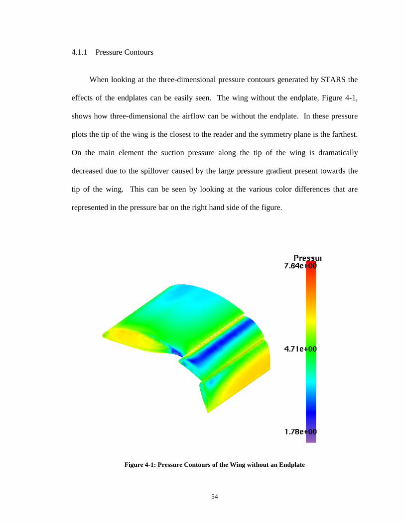
54
4.1.1 Pressure Contours
When looking at the three-dimensional pressure contours generated by STARS the
effects of the endplates can be easily seen. The wing without the endplate, Figure 4-1,
shows how three-dimensional the airflow can be without the endplate. In these pressure
plots the tip of the wing is the closest to the reader and the symmetry plane is the farthest.
On the main element the suction pressure along the tip of the wing is dramatically
decreased due to the spillover caused by the large pressure gradient present towards the
tip of the wing. This can be seen by looking at the various color differences that are
represented in the pressure bar on the right hand side of the figure.
Figure 4-1: Pressure Contours of the Wing without an Endplate

55
This effect is not only visible on the main element but can also be seen on the
second and third elements as well. In Figure 4-1, only towards the tip of the wing the
pressure contours tend to dissipate as compared to the pressure contour at the mid-span of
the model. The wings with the endplates have a more uniformly distributed suction
pressure strip along the entire length of the second element.
As for the last element on the three-element wing, the advantage of the endplate can
once again be easily seen. The non-uniform pressure gradient appears to be in the shape
of a quarter of an ellipse. Towards the tip of the third element in Figure 4-1, the wing
without the endplate, a very distinct non-uniform pressure gradient can be seen.
Although the pressure on wings with the endplates is not entirely uniform it is relatively
more so than the wing without the endplate. This does not appear on the two wings with
endplates as seen in Figure 4-2 with the style 3 endplate and Figure 4-3 with the new
endplate design. For the two figures with endplates, the edge that appears closest to the
reader is where the endplate is located. However, the endplate has been removed during
the post-process plotting so that the pressure on the elements at the tip of the wing can be
viewed.

56
Figure 4-2: Pressure Contour of Wing with Style 3 Endplate
On the wing with the style 3 endplate, Figure 4-2, the main element has evenly
distributed pressure sections as we move from the leading edge of the main element and
move back. The second element has a very uniform pressure distribution which is
recognized when comparing the tip sections of Figure 4-1 and Figure 4-2. It is not until
the third element that we see the tip pressure start to dissipate. The flow here is
extremely high, over Mach 1, and the angle of this third element is at 65° to the free
stream. When the conditions are remembered it is hard to believe that the pressure
distribution at this section of the wing is as uniform as it appears.

57
Figure 4-3: Pressure Contour of Wing with New Style Endplate
The first and second elements of the wing with the new style of endplate in Figure
4-3 appear as uniform as they were in Figure 4-2 with the style 3 endplate. The third
element for the new endplate design however appears to be more uniform then that of the
third element of the style 3 endplate. This larger new endplate controls the flow better by
reducing this spillover effect.
From another perspective, Figure 4-4 shows a side view of the endplate with the
symmetry plane in the background. This then can be somewhat viewed as the gradient
pressure that the endplate sees and thus shows once again why the airflow favors to
spillover the top edge of the endplate. The bottom does not seem to be as great of a
pressure gradient and thus only moderate spillover affects occur. This figure helped in

58
deciding how the new endplate geometry should be manipulated in order to reduce this
pressure gradient.
Figure 4-4: Pressure Gradient for Style 3 Endplate
The figure above was produced during the initial studies of the flow around the
three-element wing with the style 3 endplate and led into an investigation of the effects
that endplates have on wing performance as well as my development of the new endplate
design.
It can be seen the high-pressure on top, represented by the darker area in the figure,
extends way above the wing as well as above the top of the endplate. Ideally, from the
pressure gradient standpoint, it would be best to extend the endplate up until the pressure

59
in the far field is the same as the pressure on the endplate. There are two reasons why
this is not done. First there is a point by which the overall drag will outweigh the benefit
of extending the endplate. The second factor could be to make the structural strong
enough without bearing a lot of weight on the vehicle. I admit that these are only a few
of the many considerations that must be addressed for a real design but I was just
concerned with minor changes to endplate geometry for improvement.
A simple change in the endplate geometry was decided so the top of the endplate is
just the mirror image of the bottom. This change implemented the two changes that I felt
were necessary to improve the performance characteristics of the dragster wing. First of
all the overall height of the endplate above the wing was increased. Second there was an
increase in height at an earlier stage in the flow.
4.1.2 Cross-Flow Velocity
A different view point can be looked at that shows how the flow over this three-
element wing is effected by endplate geometry. This different perspective is cross flow
velocity cuts that show the flow on a cut plane at user specified locations on the wing.
Cross-flow velocity cuts were taken at three different positions parallel to the flow
velocity axis.
The first position was at a distance 7 inches back from the leading edge of the main
airfoil as depicted in the far left picture of Figure 4-5. This was chosen to look at early
spill over effects generated by the main element. The second cross-flow cut was at 14
inches back from the leading edge of the main element and can be seen in Figure 4-5 as
well. This position cuts through the trailing edge of the main element and the leading

60
edge of the second element. The other picture in Figure 4-5 is the last cross-flow cut was
located 20 inches back from the main element’s leading edge. This is at the trailing edge
of the last element where the most sever circulation can be seen. Each of these cut planes
will be looked at separately although they each show similar results.
Figure 4-5: Cross Flow Velocity Cuts Represented by Vertical Lines
For the first cut plane at 7 inches back from the leading edge of the main element
the spillover effect is minimal but the effects are very distinct. In Figure 4-6, without the
endplate present, a circulation can be seen coming from the top of the wing around the
tips of the wing to the suction side as discussed earlier. The figure shows a number of
different size and oriented lines. The length of the line is proportional to the speed of the
air around the dragster wing. The longer the line the faster the air is traveling. The
orientation of the line is the direction of the air at that instance for the steady-state
solution. The mid span of the half model is at the readers left hand side of these figures
and the tip of the wing is on the right hand side. There is no endplate present to deflect
this flow from circulating to the lower pressure side of the wing. From Figure 4-1 the
three dimensional effects of can been seen from a different perspective from that
discussed and shown earlier.

61
Figure 4-6: Cross-Flow Velocity 7 in. back from L.E. w/o an Endplate
If we now look at the second cross-flow plane cut, 14 inches back from the leading
edge of the main element, the circulation strength is increased. Figure 4-7 shows the
increased velocity of the flow coming around the tip of the wing.
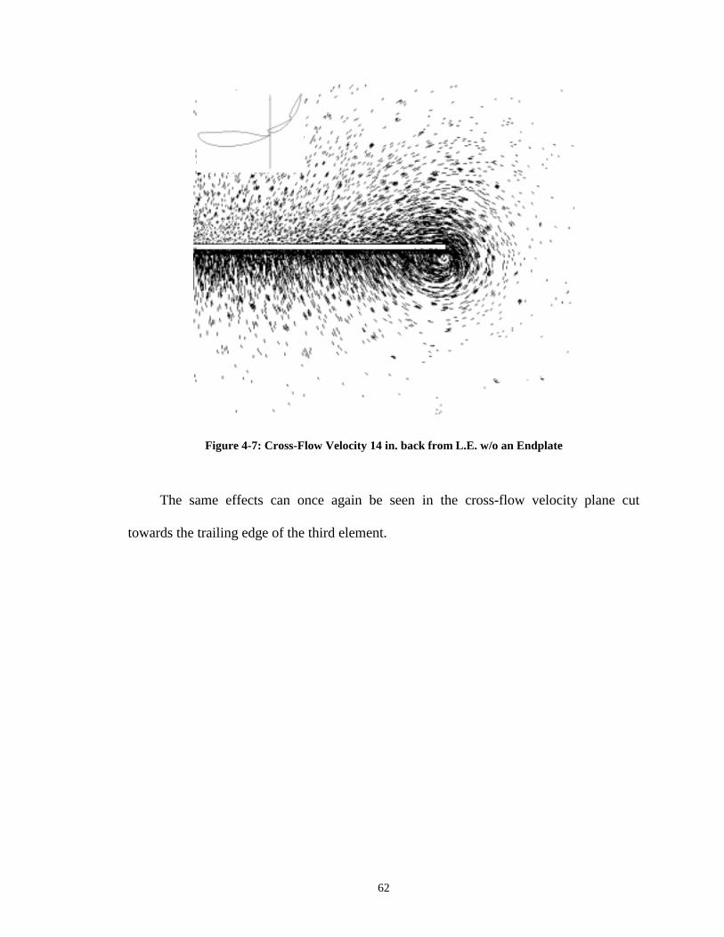
62
Figure 4-7: Cross-Flow Velocity 14 in. back from L.E. w/o an Endplate
The same effects can once again be seen in the cross-flow velocity plane cut
towards the trailing edge of the third element.

63
Figure 4-8: Cross-Flow Velocity 20 in. back from L.E. w/o an Endplate

64
Figure 4-9: Cross-Flow Velocity 7 in. back from L.E. with Style 3 Endplate
Comparing that to the wing with the style 3 endplate, Figure 4-9, it can be seen that
the airflow hits the inside of the endplate and is forced to flow up and over the endplate.
At the top of the endplate the circulation is still present but it is less noticeable and
certainly less sever. This circulation is disruptive to the suction side of the wing causing
a decrease in suction as was shown in Figure 4-1 where the pressure is very noticeable
changed. This is why endplates are so important to a low aspect ratio wing such as this
rear dragster wing. Now since this circulation arose this early on in the flow it was
decided that the height of the new endplate design needed to be increased at this location.
This was also seen previously from the pressure gradient in Figure 4-4.

65
Figure 4-10: Cross-Flow Velocity 14 in. back from L.E. with Style 3 Endplate
The spillover effects are increased as seen in Figure 4-10. Again the high pressure
gradients that are present matched with the shortness of the endplate above the airfoil
section allow this flow to spill over and disrupt the flow.

66
Figure 4-11: Cross-Flow Velocity 20 in. back from L.E. with Style 3 Endplate
The style 3 endplate has hardly any height above the trailing edge of the third
element so the effects of the endplate are very minimal. The lower portion of the style 3
endplate is beneficial to reducing the circulation around the suction side of the wing.

67
Figure 4-12: Cross-Flow Velocity 7 in. back from L.E. with New Endplate
Now looking at the new endplate design in Figure 4-13 the effects of the increased height
still shows an improvement in the reduction of the spillover effect. The airflow has to
travel a longer distance up over the endplate while decreasing its pressure gradient to the
airflow on the outside of the endplate. Thus there is a decrease in the spillover.

68
Figure 4-13: Cross-Flow Velocity 14 in. back from L.E. with New Endplate
Figure 4-14: Cross-Flow Velocity 20 in. back from L.E. with New Endplate

69
Once again it was necessary on the new endplate design to increase the height
above the third element in an attempt to reduce this circulation over the top of the
endplate. It was once again very beneficial to incorporate this height change as can be
seen in the reduced circulation in Figure 4-14.
This cross-flow velocity is only one view of what is going on as far as the flow
velocity on and around the endplate. Therefore, it is necessary to look at a cut plane
velocity profile parallel to the endplate.
4.1.3 Velocity at the Tip of the Wing
The velocity around the tip of the wing can give even more insight to the benefits of
the endplates. In Figure 4-15, a cut plane at the tip of the wing, shows the circulation
generated by the wing and how disruptive and almost how chaotic the airflow is behind
the three-elemental wings due to the lack of an endplate.
Figure 4-15: Velocity at the Wingtip without an Endplate
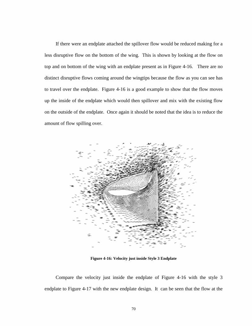
70
If there were an endplate attached the spillover flow would be reduced making for a
less disruptive flow on the bottom of the wing. This is shown by looking at the flow on
top and on bottom of the wing with an endplate present as in Figure 4-16. There are no
distinct disruptive flows coming around the wingtips because the flow as you can see has
to travel over the endplate. Figure 4-16 is a good example to show that the flow moves
up the inside of the endplate which would then spillover and mix with the existing flow
on the outside of the endplate. Once again it should be noted that the idea is to reduce the
amount of flow spilling over.
Figure 4-16: Velocity just inside Style 3 Endplate
Compare the velocity just inside the endplate of Figure 4-16 with the style 3
endplate to Figure 4-17 with the new endplate design. It can be seen that the flow at the

71
top of the new endplate design, Figure 4-17, is not as vertical as the flow at the top of the
style 3 endplate. This indicates that there is less severity to the disruptive nature of the
flow as airflow spills over. The angle of the velocity at the top of the new endplate
design becomes very similar to that of the style 3 endplate towards the tail end of the
endplate. This is due to the last wing element being at such a high angle, 65°, causing the
flow to accelerate in the direction of its projected chord line.
Figure 4-17: Velocity just inside New Endplate
4.1.4 Down Force to Drag Ratio
Another important parameter to look at the effects that endplate geometry have on
the ratio of down force to drag. This parameter allows easy comparison between the

72
different geometry. The idea is to maximize the ratio of down force to drag. It should be
noted that it is not being said that we want to maximize the amount of down force but we
want to maximize the ratio, ie get the most down force with the least amount of drag.
The forces that are calculated using STARS are not the actual down force and drag
forces directly. They are in fact non-dimensional lift and drag coefficients. However
they are not non-dimensional in the true sense but the coefficient of pressure is divided
by a factor of two. We can utilize these coefficients without further manipulation since
the ratio of the down force to drag is being calculated.
If we look at Table 4-1 at the wing without the endplate and compare it to the either
of the wings with an endplate. There is a large difference in the amount of down force
created by the wing with endplates. The drag however for the wing without the endplate
is smaller but this is not important because we are concerned with the ratio of the two
parameters.
Down Force Drag L/D Ratio No Endplate 741.9 232.4 3.19 Style 3 Endplate 960.7 258.5 3.72 New Endplate 967.6 242.6 4.0
Table 4-1: Down Force and Drag for the Three Test Cases Analyzed
If we look at the actual increase in the down force to drag ratio we can get a better
feel for how much of an improvement changing the endplate can have. As shown in
Table 4-2 there is a 16.6% increase in the ratio when we attach the style 3 endplate to the
basic wing. This ratio is further increased by 25.4% when we look at adding the new
endplate design. This data shows that the new endplate design is effective because it

73
increases the down force to drag ratio by 7.2% over the style 3 endplate while only
adding a minimal amount of area to the overall wing.
Geometry being Compared Percent Increase of Lift to Drag Ratio No Endplate to Style 3 16.6 No Endplate to New Design 25.4 Style 3 to New Design 7.2
Table 4-2: Increase of Lift to Drag Ratio for the Three Test Cases Analyzed
4.1.5 Mach Number and Coefficient of Pressure Distribution
The Mach number and coefficient of pressure distribution at the tip of the wing can
be useful in showing where the maximum amount of flow velocity and suction is
occurring, respectively. This gives the analysis a more physical comparison than just
looking at the three-dimensional color pressure plots as was shown in the beginning of
the section.
The pressure distribution in Figure 4-18 shows the coefficient of pressure for each
of the three test cases analyzed. The first case where there was not an endplate, the
coefficient of pressure on the suction side is about –2.5 on the first element as compared
to –3 for the wings with the endplates. For the second wing element the difference in
pressure on the suction side between the wing with an endplate and the wing without an
endplate is about 1.5. The suction side of the third element and the positive pressure
sides of all three-elements do not show a dramatic difference but there is still a moderate
change.
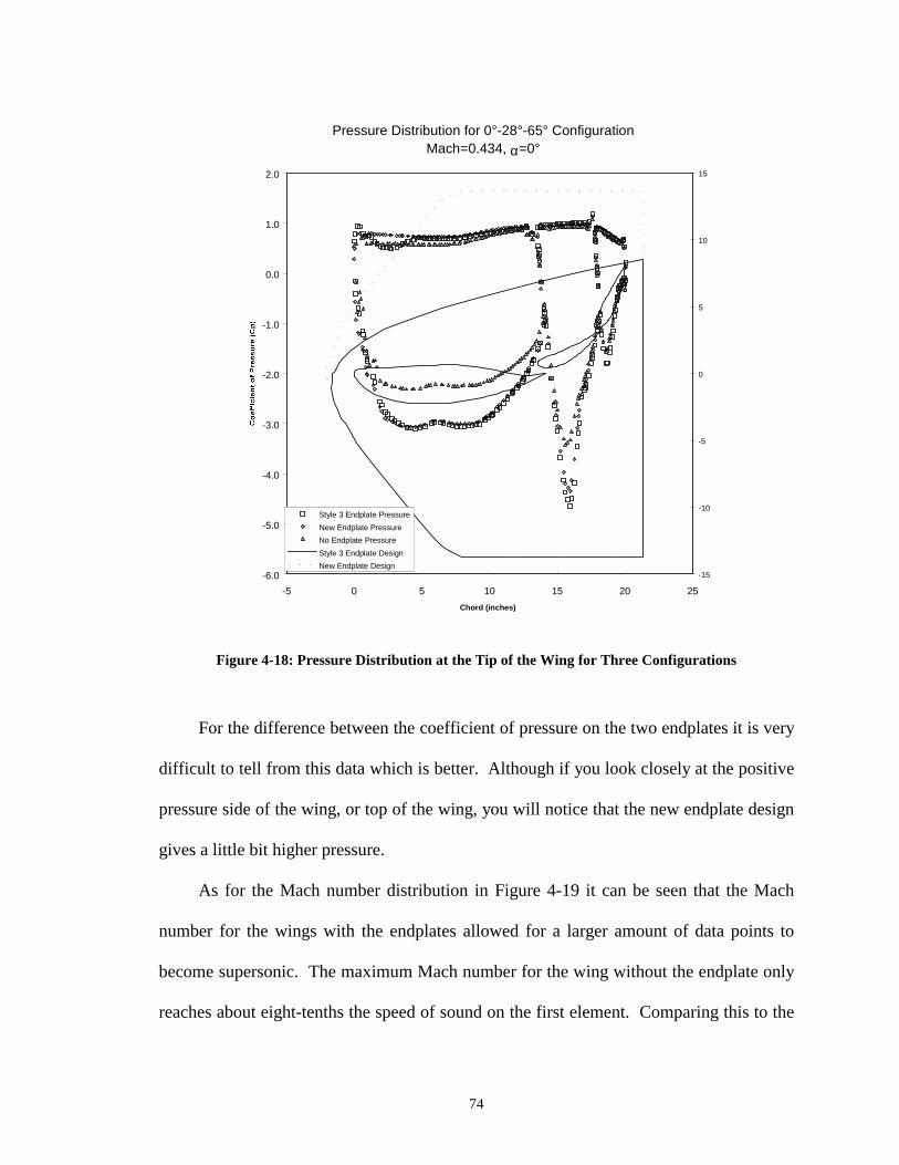
74
Pressure Distribution for 0°-28°-65° Configuration Mach=0.434, α=0°
-6.0
-5.0
-4.0
-3.0
-2.0
-1.0
0.0
1.0
2.0
-5 0 5 10 15 20 25Chord (inches)
-15
-10
-5
0
5
10
15
Style 3 Endplate PressureNew Endplate PressureNo Endplate PressureStyle 3 Endplate DesignNew Endplate Design
Figure 4-18: Pressure Distribution at the Tip of the Wing for Three Configurations
For the difference between the coefficient of pressure on the two endplates it is very
difficult to tell from this data which is better. Although if you look closely at the positive
pressure side of the wing, or top of the wing, you will notice that the new endplate design
gives a little bit higher pressure.
As for the Mach number distribution in Figure 4-19 it can be seen that the Mach
number for the wings with the endplates allowed for a larger amount of data points to
become supersonic. The maximum Mach number for the wing without the endplate only
reaches about eight-tenths the speed of sound on the first element. Comparing this to the

75
first element for the wings with endplates, the Mach numbers almost reaches the speed of
sound. For the second wing element the effect of the endplate is about the same. On the
third wing element there is not a noticeable difference.
Mach Distribution for 0°-28°-65° Configuration Free Stream Mach=0.434, α=0°
0.0
0.2
0.4
0.6
0.8
1.0
1.2
1.4-5 0 5 10 15 20 25
Chord (inches)
-15
-10
-5
0
5
10
15
Style 3 Endplate MachNew Endplate MachNo Endplate MachStyle 3 Endplate DesignNew Endplate Design
t
Figure 4-19: Mach Distribution at the Tip of the Wing for the Three Configurations
The topside of the wing shows a pretty uniform Mach number distribution between
the three test cases analyzed. There is a slight increase in Mach number for the new
endplate design over the style 3 endplate. It is believed that this can be linked to the
reduced spillover affect seen on the top of the endplate.

4.2 Gap Spacing Comparisons for a Three-Element Dragster Wing
Gap spacing can affect the performance characteristics of these wings as well.
Therefore the effects of gap spacing between the elements of a multi-element wing will
be studied This gap spacing is critical because it allows a certain amount of flow to pass
between the elements and this amount of flow is very sensitive when looking at the
performance of a multi-element wing.
The best way to look at this is a velocity cut plane at the mid span of the half model
as seen in Figure 4-20. The multi-element wing has a 0°-28°-65° configuration at a Mach
umber of 0.434 for an overall angle of attack of 0°. As a reminder the configuration, 0°-
28°-65°, refers to the angle of attack of each of the three individual elements.
0°–28°-65° ConfigurationMach = 0.434 α = 0°76
Figure 4-20: Velocity Profile of Wing with Original Gap Spacing

Pay attention to the gap size in between the elements as well as the flow field
around and in between the gaps when looking at Figure 4-20 and Figure 4-21. It can be
seen in Figure 4-20 that the flow around the second element, particularly the flow right in
front of the second element, is more smooth looking than the flow around the second
element in Figure 4-21. In the latter mentioned figure the gap size is too large and allows
too much air to flow to pass. This causes a Ventura affect before the second element
letting a massive amount of air through the gap which disrupts the flow. The same
effects can be seen in the flow around the third element.
be
flow
0°–28°-65° ConfigurationMach = 0.434 α = 0°77
Figure 4-21: Velocity Profile of Wing with Modified Gap Spacing
When looking at the flow at the trailing edge of the third element another effect can
seen. With the increase in gap spacing the appears to be a flow separation. An Euler
solver is unable to predict flow separation but the chaotic flow just aft of the trailing

78
edge of the third element shows signs of flow separation. It almost appears to have a
circulation around this area and is very disruptive to the flow.
When the gap size was increased there was a decrease in the amount of down force
generated. The decrease in down force was 6.8% under the amount of down force
generated by the original gap spacing. The increased gap spacing also resulted in an
increased the down force to drag ratio by 15.7%.
4.3 Angle of Attach Comparisons of Three-Element Dragster Wings
The effects of angle of attack on dragster wing with the style 3 endplate was studied
to see how it affected the performance of the wing. The configuration was a 0°-28°-65°
wing that was varied at two different angles of attack being 0° and 5°. The reason for this
analysis is due to the top-fuel dragster teams wanting to vary the angle of attack on the
rear wing to change the performance characteristics. These comparisons were looked at
both through pressure cut plane data as well as down force and drag data, which was
generated using STARS.
The pressure distribution data, as seen in Figure 4-22, is a pressure cut plane at mid
span of the half model. As seen in the figure below there is little differences for the last
two elements in the coefficient of pressure between each of the two angles of attack.
However, the main difference appear on the first element and are mainly present toward
the leading edge of that element. When the whole wing is rotated 5°, tilted forward, the
suction pressure has a greater distribution than the wing at 0° angle of attack. When
looking from three quarters of the way back from the leading edge of the first element all
the way back to the trailing edge of the third element there is little difference.

79
Figure 4-22: Pressure Plots for Angle of Attack Comparisons
For a feel on how much it affects the performance of the wing it is necessary to
look at the down force and drag of the wing. An increase in angle of attack to α = 5°
increases the down force by 8.9%. This might be considered good if all we were
interested in was down force the drag must be considered in our case. The drag also
increased but increased by 20.4%. This is greater than the increase in down force and
therefore it decreases the down force to drag ratio by 9.7%. Based upon wing
performance alone this increase in angle of attack would be a mistake.

80
4.4 World Record Performances
It should be noted that the improvement to the endplate design over the previously
used style 3 endplate helped two top-fuel dragster teams break two different world
records. Two weeks after the introduction of this new endplate Larry Dixon piloted a
dragster owned by Don Prudhomme to the quickest elapse time record in the quarter mile
history. At Houston Park Raceway in April of 1999 he posted a 4.486 second run beating
the previous record by 0.03 seconds. Weeks later, with the same new endplate design,
Tony Schumacher at the Checker-Schuck's Kragen Nationals downed the top-fuel
dragster speed record reaching 330.23 mph in the quarter mile.
Granted the wing was not the only factor involved in the record-breaking runs but
given the vast improvements they can be considered to be somewhat responsible. These
wings can require close to 2000 hp to drag them through the air. The new endplate
design reduced the drag and thus reduced the needed horsepower to drag the wing
through the air. This additional horsepower can then go to acceleration and thus
potentially allowing the vehicle to reduce the elapsed time or increase the top speed.
4.5 Using the Dragster Model to Analyze the Problem
Since the model matched the actual data well it is now the objective to see what
affects the aerodynamics has on the performance of the dragster.
The first figure below, Figure 4-23, shows the actual input power to a dragster.
This is used for the input power to the dragster for the validation analysis in the previous
section. Along with this input power is the power left over to accelerate the dragster and
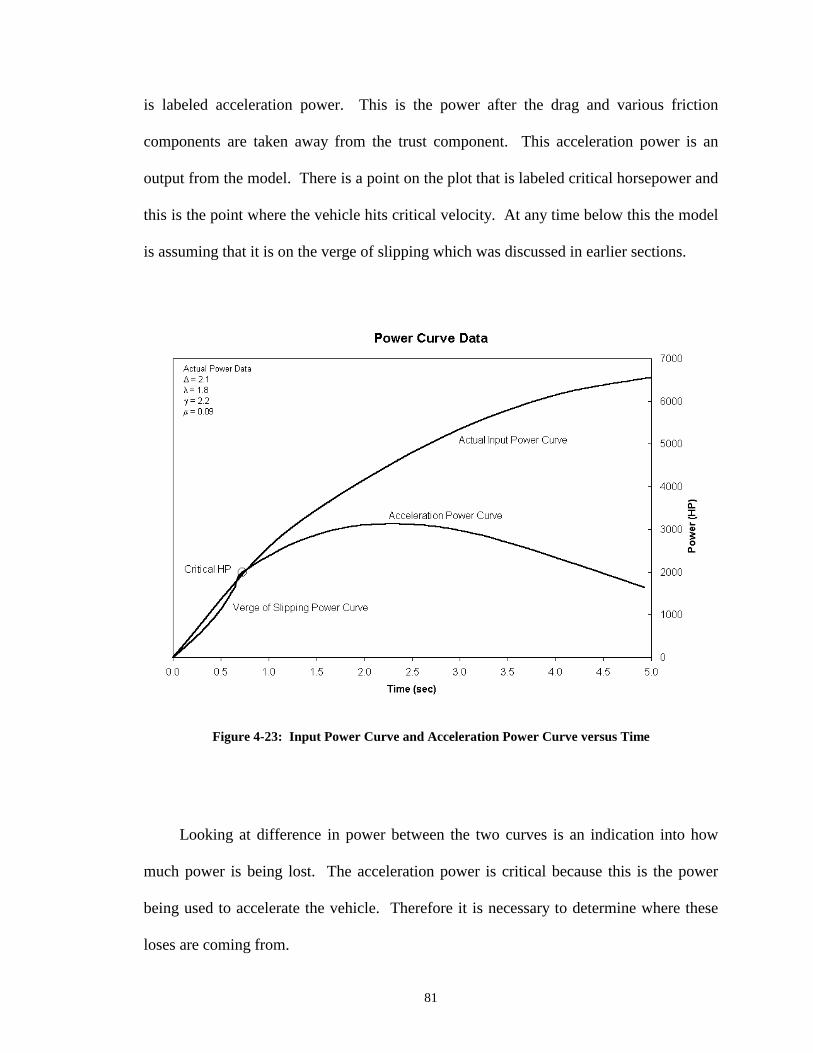
81
is labeled acceleration power. This is the power after the drag and various friction
components are taken away from the trust component. This acceleration power is an
output from the model. There is a point on the plot that is labeled critical horsepower and
this is the point where the vehicle hits critical velocity. At any time below this the model
is assuming that it is on the verge of slipping which was discussed in earlier sections.
Figure 4-23: Input Power Curve and Acceleration Power Curve versus Time
Looking at difference in power between the two curves is an indication into how
much power is being lost. The acceleration power is critical because this is the power
being used to accelerate the vehicle. Therefore it is necessary to determine where these
loses are coming from.

82
In the next figure, Figure 4-24, there are two additional lines. One is the amount of
power that the car absorbs due to drag and friction. Looking at the drag coefficient of the
wing in comparison, Table 4-3, with the rest of the components under consideration
showed that it was a major factor in this power loss.
Coefficient of Drag Scaled to Wing Area Wheels Cl -0.14142 Cogotti for Rotating Wheels Cd 0.45489 Cogotti for Rotating Wheels Wing Induced Cl -2.47700 STARS Cd 0.60100 STARS Wing Area Top Cd 0.00963 Estimated Wing Area Endplate Cd 0.00380 Estimated Body Cd 0.01733 Estimated by 3D Wedge
Table 4-3: Lift and Drag Coefficients for the Dragster Model

83
Figure 4-24: Power Curves along with Drag Power versus Time
At the end of the race the wing is making up almost two thirds of the total loss of
power of the dragster. It is necessary to find out how changing this drag would affect the
performance of the dragster. In order to do this the model was run with different drag
coefficients while keeping constant the lift to drag ratio. This was done for four drag
coefficients and six different lift to drag ratios and the results can be seen in Figure 4-25.

84
Figure 4-25: Elapsed Time and Speed Data for Varying Drag Coefficient
This figure shows how much reducing the drag coefficient can improve the elapsed
time of the dragster as well as how much it can increase the top speed. The X on the
figure shows a dragster whose lift and drag characteristics were estimated and the wing
data was generated from STARS for the finnew wing design. The finnew design is a
wing that is currently being used by several dragster teams. The elapsed times and top
speed are not current with the times and top speeds of today's dragsters but it must be
understood that the input power used was from actual data that might not meet the siput
power data of a dragster now. The idea of this is to not look at the times and speeds that
were achieved but to look at the trends of changing the parameters.

85
Another point on the graph to look at is the + mark. This run is the same dragster
but the wing is taken off so that is produces not down force or drag force. It has a lower
elapsed time because the reduction in drag but the catch is that the driving style would
have to change. This can better be seen below in Figure 4-26.
Figure 4-26: Elapsed Time and Critical Speed Data for Varying Drag Coefficient
The critical speed is over twice that of the dragster with the wing. This means that
there is not enough down force early on and with the given input power curve it is not
able to give full power until it reaches this speed. If it had more power earlier than this
point than the tires would slip and loose traction. This means that the driver must be less

86
aggressive during the race in the dragster without the wing. This shows how important
reducing this drag can be as far as performance is concerned.
The question then is whether running a dragster without a wing is the best or is
there some other way that is better. It is still not know how the lift coefficient affects the
performance of the dragster. The question must be answered then how much lift does the
dragster need and at what point on the track is the lift needed? The best way to figure
this out is to vary the lift coefficient for a fixed lift to drag ratio. This data is plotted
below in Figure 4-27.
Figure 4-27: Elapsed Time and Speed Data for Varying Lift Coefficient

87
Looking at the constant drag coefficient lines (Cd=0.6 and Cd=0.4) backs up the
theory from before that to get a better elapsed time it is necessary to reduce the drag
coefficient. The lift coefficient can be looked at as well showing that for a constant lift to
drag ratio reducing the lift coefficient from -3 to -0.5 will reduce the elapsed time and
increase the top speed of the dragster. Once the dragster gets below a lift coefficient of
around -0.5 the elapsed time increases. This starts to show that reducing the lift
coefficient down to zero does not help the performance of the dragster.
In this region where there is a low lift coefficient and a high lift to drag ratio the
performance of the dragster suffers because of the critical speed is too great for the car to
have its best run. This can better be seen in Figure 4-28. The elapsed time is around 175
mph. This is somewhat misleading because the drag coefficient for the dragster cannot
be this low unless significant modifications to the aerodynamics of the overall car is
made. Looking at the run of the dragster without the wing it has a drag coefficient
between 0.4 and 0.6. The drag from the large open wheels and the body of the dragster
are to blame for this drag.

88
Figure 4-28: Elapsed Time and Critical Speed Data for Varying Lift Coefficient
These figures are somewhat misleading because if we are looking at changing the
wing on the car then it is not simply looking at just changing the lift coefficient. Lets say
for instance that you were looking at changing the angle of attack of a wing and you were
able to increase the lift coefficient from -1 to -2. It is clear at to where the lift coefficient
lines are and how they affect elapsed time but what now happens is that when the angle
of attack changed not only did the lift coefficient change but the lift to drag ratio changed
as well. So it is not as easy to see how it is affected because the lift to drag ratio is not
constant and the user of the figures must determine the new lift to drag ratio.
Wing configurations will be plotted later in this paper but what I want to do is to
talk about designing a new wing. From looking at the previous plots a wing that has a
89
lower lift coefficient with the highest lift to drag ratio will get us into a lower elapsed
time. As was mentioned earlier the design of a boxwing was considered for many
reasons and the results from STARS will be discussed in the next section.
4.6 Steady Results of Boxwing Design
The new boxwing design was analyzed computationally using STARS. The
performance characteristics of this wing compared to the old style three-element wings
will be looked at in this section. Various plots and figures are provided to show a variety
of different comparisons between the wings including pressure plots, mach plots,
coefficient of lift versus angle of attack, coefficient of drag versus angle of attack,
coefficient of lift versus coefficient of drag, and several others.
4.6.1 Decalage Angle Comparisons
STARS simulations were performed for various boxwing configurations. The
decalage angle was varied for three different angles. For every decalage angle the angle
of attack was then varied over a wide range to find the characteristics of this particular
type of wing. This data was used to analyze the performance of this wing and then use it
also to compare this boxwing to existing wings.

90
4.6.1.1 Pressure Plots
The pressure plots are for three different decalage angles for a wide range of
overall wing angle of attacks. The side view of the wing at zero angle of attack is also
plotted on the graphs in order to clarify the two distinct sections of pressure distribution
on the plots.
The two regions of pressure distribution clearly show the difference in loading of
the two wings. The front wing is loaded too much while the back wing is not loaded
enough. The reason that this happens is because the influence of the wings on each other.
The front lower wing reduces the effective angle of attack of the back upper wing and the
back upper wing increases the effective angle of attack that the lower front wing sees.
This is why we change the decalage angle as to try to evenly load these wings to account
for the influences of the wings on each other.

91
Figure 4-29: Pressure Plot for Boxwing at 0 Degree Decalage Angle
As can be seen in Figure 4-30 the pressure distribution is starting to level out and
provide a more efficient wing. In this figure the decalage angle is 8°. As mentioned
earlier the difference in angles between the two wings is the decalage angle. When the
lower front wing is parallel to the ground, at a zero angle of attack, the upper back wing
is turned at an 8° angle, where the tail of the wing is up.
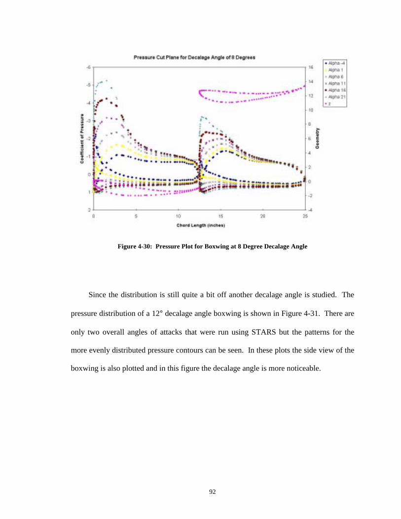
92
Figure 4-30: Pressure Plot for Boxwing at 8 Degree Decalage Angle
Since the distribution is still quite a bit off another decalage angle is studied. The
pressure distribution of a 12° decalage angle boxwing is shown in Figure 4-31. There are
only two overall angles of attacks that were run using STARS but the patterns for the
more evenly distributed pressure contours can be seen. In these plots the side view of the
boxwing is also plotted and in this figure the decalage angle is more noticeable.
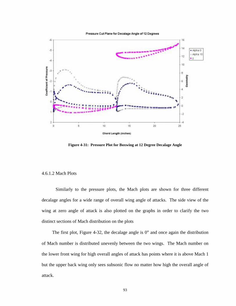
93
Figure 4-31: Pressure Plot for Boxwing at 12 Degree Decalage Angle
4.6.1.2 Mach Plots
Similarly to the pressure plots, the Mach plots are shown for three different
decalage angles for a wide range of overall wing angle of attacks. The side view of the
wing at zero angle of attack is also plotted on the graphs in order to clarify the two
distinct sections of Mach distribution on the plots
The first plot, Figure 4-32, the decalage angle is 0° and once again the distribution
of Mach number is distributed unevenly between the two wings. The Mach number on
the lower front wing for high overall angles of attack has points where it is above Mach 1
but the upper back wing only sees subsonic flow no matter how high the overall angle of
attack.

94
Figure 4-32: Mach Number Plot for Boxwing with 0 Degree Decalage Angle
The same patterns for the pressure plot for the 8° decalage angle occur for the Mach
plot as well. In Figure 4-33 the distribution of Mach starts to even out. For the 21° angle
of attack the upper back wing almost sees Mach 1 while the lower front wing sees Mach
numbers to almost Mach 1.4.

95
Figure 4-33: Mach Numbar Plot for Boxwing at 8 Degree Declage Angle
The 12° decalage angle shown in Figure 4-34 once again looks like that of the
pressure plot for the 12° decalage angle as expected. The angles of attack larger than 10°
were not run but the patterns can be seen as the Mach distribution evens out even more.
More decalage angles could have been run but the idea is not to get this wing to its
optimal design but to look at a whole new approach to dragster wings to see if a better
performance can be achieved which will be talked about in the next section.

96
Figure 4-34: Mach Number Plot for Boxwing at 12 Degree Decalage Angle
4.6.2 Boxwing and Three-Element Wing Comparisons
In an attempt to compare these different wing types certain wing performance
characteristics were studied and plotted. Some of these include coefficient of lift versus
angle of attack, coefficient of drag versus angle of attack, coefficient of lift to coefficient
of drag, and coefficient of lift to drag versus angle of attack.

97
Figure 4-35: Coefficient of Lift vs Angle of Attack
The coefficient of lift versus angle of attack plot in Figure 4-35 shows how the lift
coefficient a particular wing has when it is adjusted to a certain angle of attack. It can be
seen that the wing labeled finnew, which is the three-element wing at a 0°-28°-65°
configuration with the new endplate, has quite a bit higher CLα than the other boxwing
designs. The boxwing design with a decalage angle of 12 degrees has the potential of
reaching the same coefficient of lift as the finnew wing if the boxwing is set to an overall
angle of attack of 20°.

98
Figure 4-36: Coefficient of Drag vs Angle of Attack
The next plot above, Figure 4-36, is a plot of the coefficient of drag versus angle of
attack.
This figure is deceiving at first because it looks like the boxwing design has a lot
lower drag coefficient than the three-element design. This is not necessary true because
the boxwing at these lower angles of attack does not produce the same lift as the three-
element wing at the same angles of attack. It might be better to look at the coefficient of
drag to the coefficient of lift to see a better comparison.

99
Figure 4-37: Coefficient of Drag vs Coefficient of Lift
Figure 4-37 above represents the coefficient of drag versus the coefficient of lift
plot. This allows for the comparison of how efficient the wings can be if you will. This
tells us how much lift we can get out of a wing with the punishment of the amount of
drag that the wing had by nature.
It is hard to compare the boxwing to the three-element wing in this plot because
they do not have the same lift coefficient. Therefore it is better to look at a plot that
compares the ratio of the coefficients of lift to drag versus the coefficient of lift. This
gives a better comparison of the wings.

100
Figure 4-38: Coefficient of Lift to Drag vs Coefficient of Lift
This plot of the coefficients of lift to drag versus the coefficient of lift, shown in
Figure 4-38, allows us to see the efficiency of the wings in a way. For a given coefficient
of lift that is desired, a wing can be picked based upon its lift to drag ratio. A wing that
has a better lift to drag ratio is punished less, in terms of drag, when there is an increase
in the amount of lift produced. It is ideal to have a higher lift to drag ratio.
4.7 Dragster Performance Comparisons using the Dynamic Model
This portion of the results is what is the most important. Even though all the
previous comparisons on wing performance was done the individual wing characteristics
was not what this research was about fully. The true results is how these different wings
and how the changes to these wings truly effected the overall performance of the

101
dragster. The improvements to the performance of the individual components is needed
but the improvements should not be recognized without knowing how they will improve
the performance of the dragster. Large improvements to a component might not
necessarily provide large improvements to the performance of the dragster and vise versa.
A true test is to input these component changes into a dynamic model for the
dragster and see how they affect the quarter mile time and speed. Since the dragster
teams are concerned with the finishing times and top speeds of the dragsters then it is
important to be able to give the teams a figure on how certain changes will affect the time
and speed of their vehicles.
4.7.1 Performance Data for Various Rear Wings
Wing data from an actual dragster as well as the new boxwing design was used
when running the model to determine how the aerodynamic changes would affect the
performance. The wings were varied at different angles of attack since most dragster
teams tamper with this feature. The data was plotted on the charts that were generated
earlier and the results are shown in Figure 4-39.
The figure shows two wings with the first being the finnew design. This is a current
wing that is being used on dragsters. It is varied for three different angles of attack from
0° to 10°. As the angle of attack increases so does the elapsed time while the top speed
of the vehicle decreases.
The second wing that is analyzed is the boxwing configuration with an 8° decalage
angle. This to was varied for several angles of attack. The angles range from -4° to 21°
and are in increments of 5°. When the chord of the lower wing is parallel to ground then

102
the angle of attack is set to be at 0°. As the angle of attack is lowered from 21° the
elapses time decreases and the top speed increases up until the wing is set to 1°. When
the wing is set to a lower angle of attack the performance of elapsed time decreases but
the top speed increases.
Figure 4-39: Elapsed Time and Speed Data with Different Wing Configurations
The next figure shows how this data affects the elapsed time and the critical speed
of the dragster.

103
Figure 4-40: Elapsed Time and Speed Data with Different Wing Configurations
4.7.2 Performance Data for Various Input Power Curves
More data was studied looking at how the power input curve distribution effects the
performance of the dragster. The wing and car properties were held constant and the
input horsepower curve was varied. There are three power curves that were studied as
can be seen in Figure 4-41.
The actual power curve depicted on the figure is a curve fit from an actual run of a
top-fuel dragster. This is the power curve used as an input to the model to generate all
the other model data. Two other power curves were generated to look at how and in what
way would the horsepower curve effect the performance of the dragster.

104
Figure 4-41: Model Power Input Curves to look at Horsepower Effects
This data was used for certain coefficients of lift and a constant drag coefficient of
1.0 to generate Figure 4-42, below. As can be seen the actual power curve is in the
middle of the figure. When a lower power curve is used, simulating a dragster that has a
reduced amount of power or maybe a slower start than usual, depicted by power curve
three in Figure 4-41, the elapsed times increase and the top speed decrease considerably.
For this power curve data the coefficients of lift can be looked at in more detail. For a
higher lift coefficient like -3 the elapsed time is higher than that with a lower coefficient
of lift such as -0.5. This is a different trend for larger power curves where the elapsed

105
time improves as the coefficient of lift is increased as can be seen for the actual power
curve as well as power curve two.
Power curve two as seen in Figure 4-41 increases the top speed and decreases the
elapsed time of the dragster. The power curve has a higher horsepower curve than that of
the actual power curve. There is an improvement in the performance of the dragster.
Even having this higher power curve with a coefficient of lift of -0.5 compared to the
actual power curve with a higher coefficient of lift, such as -3, produces a lower elapsed
time.
Figure 4-42: Power Curve Input Effects on Elapsed Time and Top Speed
This tells us that more power is important when it can be generated but whether
more that power curve two is better has not been studied. Lower power curves, such as

106
power curve three, start to show that if the dragster has a reduction in power that it is
better to have a lower lift coefficient. These three power curves were the only ones
studied but a lot can be learned from them as far as performance effects are concerned.
What also should be noted in Figure 4-42 is the performance effects of the dragsters
with and without the rear wing. The dragsters with the wings are represented by the "X"
marks in the figure and the dragster without the wing is represented by the "+" marks.
For the lower power curves the dragster without the wing out performs the dragster with
the rear wing. For a dragster with greater power as in the actual power curve data, the
dragster without the rear wing still has an advantage, elapsed time wise, over the dragster
with the wing. When the highest power curve is looked at, power curve 2, the dragster
with the wing has a lower elapsed time that the dragster without a rear wing.
This tells us that for lower powered dragsters, keeping all other parameters the
same, it is better to take the rear wing off. If a dragster were to increase the power used
today then the team would be more advantageous to put the wing on if having a rear wing
or not were their only choices. I do want to reinstate the fact that these are not the only
choices. As was shown previously, for the current dragsters today, using a lower drag
wing with higher lift to drag ratios is better than no wing but using no rear wing right
now is better that using the wings that the dragsters are currently using.

107
CHAPTER 5
5. CONCLUSIONS AND RECOMMENDATIONS
5.1 Conclusions
By modeling the performance of a dragster and looking at the effects that
aerodynamics has of the performance of a dragster has proven very beneficial. It gives us
an insight into the questions of how much down force is needed and how changing these
aerodynamic characteristics will truly effect the performance of the dragster. It was
always said that these dragsters want as much down force as possible but from this model
it is not necessarily true. What was shown to be the most beneficial is the reduction of
the drag and the reduction of the coefficient of lift up to a certain point. The
improvement to the lift to drag ratio is important as well and was the case for the new
endplate design.
5.1.1 Dynamic Dragster Model
The dragster model matched actual top-fuel dragster data very well. It functioned
in a manner that allowed me to show how each of the aerodynamic parameters, lift and
drag, affect the performance of the dragster. It led to the study of improving wind design

108
by improving the current wing and also led to the knowledge of how a different style of
wing might improve the performance even better.
5.1.2 Endplate Effects on a Top-Fuel Dragster Rear Wing
The study of endplate effects on top-fuel dragster wings proved to be beneficial in
understanding how and to what extent an endplate has on the flow over a wing. The
results presented led to vast improvements in rear wing design and helped two different
top-fuel dragsters prevail on top of two different world records.
The addition of the new endplate improved the effectiveness of the wing. It
allowed for a more uniform load distribution over the entire span of the wing. This in
turn produced a greater down force and since it reduced the amount of spillover, or
disruptive flow to the suction side, it reduced the amount of induced drag. With the new
endplate design there was an increase of almost 7.2%, over the wing with the style 3
endplate, in terms of the ratio of down force to drag.
It should be noted that this solution does not take into consideration compressibility
effects and since there is not any experimental data to compare it to the percent error
cannot be provided.
5.1.3 Boxwing Design
The boxwing design compared to the currently used dragster wings showed much
improvement to the overall performance of the dragster. The model was able to show
how the lift and drag effected the performance of the dragster and this provided the

109
insight as to what characteristics were needed for the new dragster rear wing. With this
wing we were able to get to a lower elapsed time and a higher top speed.
This was done to reduce the drag since it takes so much horsepower to drag the
currently used dragster rear wings through the air. By reducing the induced drag of the
wing we were able to shift the horsepower that was saved into accelerating the car. This
amounted to quicker elapsed times and faster speeds which was one of the motives
behind this research.
5.2 Recommendations
Improvement to this research can be made in a number of ways. Recommendations
will be made starting with modeling of the dragster and going thru to each of the parts of
this project all the way to the boxwing design.
5.2.1 Dynamic Dragster Model
Although the dragster model worked well in showing the trends of the aerodynamic
affects on performance it did not have some features that might be very beneficial to
dragster teams. Many of the parameters for this program were not actual parameters but
estimated parameters because this information was hard to get. Future work might
include collecting data from actual runs that will show how close the estimations were to
the actual parameters. The parameters did give accurate enough results to enable me to
match actual run data that was shown in the validation section.

110
Other recommendations might be to add other features to the program that might
enable a dragster team to get the dragster ready for a particular track and weather
conditions. Such features could include track conditions as far as where the track is
slippery or any conditions that a dragster team might look for when setting up the
dragster. A feature that might be nice is adding a clutch that you can set up to shift for
given parameters.
5.2.2 Endplate Design Improvements
Although improvements to the wing characteristics were made by changing the
endplate geometry there can still be some changes made to further optimize the design.
The shape of the wing was not truly optimized but merely a change in design of the
endplate was chosen that would see the extent of the improvement that such a change
could make. Further design could be done to improve upon this endplate so as to truly
optimize it for design.
Another consideration would be to consider the cost of the wing and try to make
changes that could not only improve the design but also reduce the cost of the wing itself.
Since the wings are made of carbon fiber the cost can be expensive to produce.
Improvements in design could reduce the amount of material used and therefore reduce
the cost.
Further, structural analysis could be done using a finite element code, such as
STARS, to look at the strength of the various parts of the wing. The inner workings of
the wing as well as the attaching mechanism should be studied to see if modification
could be done to reduce weigh.

111
5.2.3 Boxwing Design
The boxwing design showed to reduce the elapsed time of the dragster as well as
increase the top speed when compared to a wing that is currently being used on several
top-fuel dragsters. This wing was in no way optimized to its full potential. There are
many parameters that can be looked at such as the decalage angle as well as the endplate
design used and looking into the structural and support of the wing could also be studied.
The decalage angles of 0°, 8° and 12° were studied and analyzed. Refining these
angles would more than likely show better performance characteristics could be achieved.
Having this range allowed me to see how this parameter affected this wing performance
but not a lot of time was spent on getting the best decalage angle.
5.2.4 Stability of the Dragster
It is good to note that before the implementation of this new dragster wing that
careful analysis be done on the stability of the dragsters. Since these wings have less
drag and they allow the dragsters to function at higher speeds they should be once again
analyzed to make sure that they are still safe.

112
BIBLIOGRAPHY
Arena, A.S. Jr. (1998-2000). Associate Professor, Oklahoma State University. Personal Communications.
Cogotti, A., "Aerodynamic Characteristics of Car Wheels," International Journal of
Vehicle Design, Technological Advances in Vehicle Design Series, SP3, Impact of Aerodynamics on Vehicle Design, pp. 173-196, 1983.
Gupta, K.K., "STARS-An Integrated, Multidisciplinary, Finite-Element, Structural,
Fluids, Aeroelastic, and Aeroservoelastic Analysis Computer Program", NASA Technical Memorandum 4795, 1997.
Hallum, C., "The Magic of the Drag Tire", Society of Automotive Engineers Inc. Paper
No. 942484, 1994. Hawks, R.J. and C.L. Sayre, "Aerodynamics and Automobile Performance," Advances in
Road Vehicle Aerodynamics 1973, pp. 1-13, BHRA Fluid Engineering (1973). Katz, J., Race Car Aerodynamics: Designing for Speed, Robert Bentley Publishers, 1995. Milliken, W.F. and D.L. Milliken, Race Car Vehicle Dynamics, Society of Automotive
Engineers International, 1995. Munson, B.R., Young, D.F., and T.H. Okiishi, Fundamentals of Fluid Mechanics, 2nd
Edition, John Wiley and Sons Inc., 1994. Raymer, D.P., Aircraft Design: A Conceptual Approach, 2nd Edition, American Institute
of Aeronautics and Astronautics, 1992. Selig, M., Airfoil data for Selig 1223, University of Illinois, Urbana, Illinois, July 14,
1995. Smith, A.M.O., "High Lift Aerodynamics," Journal of Aircraft, Volume 12, Number 6,
1975, pp. 501-530. Stapleford, W.R. and G.W. Carr, "Aerodynamic Characteristics of Exposed Rotating
Wheels", MIRA Report No. 1970/2, 1969.

113
Stephens, C.H., “CFD-Based Aeroservoelastic Predictions on a Benchmark Configuration using the Transpiration Method”, Masters Thesis, Oklahoma State University, July 1998.
Winn, R.C., Kohlman, D.L., and Kenner, M.T., "Optimal Wing Design for Top-Fuel
Dragsters", American Institute of Aeronautics and Astronautics, Paper No. 99-0464, 1999.
2000 NHRA Rulebook, National Hot Rod Association, 1999.

114
APPENDICES

115
APPENDIX A-1
STARS-CFD Geometry Data File (fin.sur)
1 Geometry definition…fin 26 12 Curves 1 1 21 -123.0000 0.000 0.000 -121.7700 0.000 24.5680 -116.8500 0.000 54.6612 -107.0100 0.000 87.2439 -89.7900 0.000 123.4354 -68.8800 0.000 153.9419 -39.3600 0.000 184.8124 -7.3800 0.000 208.6080 29.5200 0.000 227.5475 71.3400 0.000 240.5142 123.0000 0.000 246.0000 174.6600 0.000 240.5142 216.4800 0.000 227.5475 253.3800 0.000 208.6080 285.3600 0.000 184.8124 314.8800 0.000 153.9419 335.7900 0.000 123.4354 353.0100 0.000 87.2439 362.8500 0.000 54.6612 367.7700 0.000 24.5680 369.0000 0.000 0.000 2 1 21 -123.00000 0.000 0.000 -121.77000 0.000 -24.56802 -116.85000 0.000 -54.66120 -107.01000 0.000 -87.24390 -89.79000 0.000 -123.43542 -68.88000 0.000 -153.94188 -39.36000 0.000 -184.81242 -7.38000 0.000 -208.60800 29.52000 0.000 -227.54754 71.34000 0.000 -240.51420 123.00000 0.000 -246.0000 174.66000 0.000 -240.5142 216.4800 0.000 -227.54754 253.3800 0.000 -208.6080 285.3600 0.000 -184.81242 314.8800 0.000 -153.94188
335.7900 0.000 -123.43542 353.0100 0.000 -87.24390 362.8500 0.000 -54.66120 367.7700 0.000 -24.56802 369.0000 0.000 0.000 3 1 36 0.000 0.000 0.000 0.0355 0.000 0.1008 0.0500 0.000 0.1280 0.1250 0.000 0.2295 0.1875 0.000 0.2700 0.3438 0.000 0.3338 0.5000 0.000 0.3677 0.7500 0.000 0.3750 1.0000 0.000 0.3969 1.5000 0.000 0.4207 2.0000 0.000 0.4431 2.5000 0.000 0.4654 3.0000 0.000 0.4892 3.5000 0.000 0.5135 4.0000 0.000 0.5392 4.5000 0.000 0.5639 5.0000 0.000 0.5880 5.5000 0.000 0.6091 6.0000 0.000 0.6275 6.5000 0.000 0.6417 7.0000 0.000 0.6471 7.5000 0.000 0.6386 8.0000 0.000 0.6120 8.5000 0.000 0.5693 9.0000 0.000 0.5103 9.5000 0.000 0.4324 10.000 0.000 0.3359 10.5000 0.000 0.2299 11.0000 0.000 0.1166 11.5000 0.000 0.000 12.0000 0.000 -0.0946 12.5000 0.000 -0.1530 13.0000 0.000 -0.1589 13.5000 0.000 -0.1024 14.0000 0.000 0.0251 14.1000 0.000 0.000 4 1
36 0.000 0.000 0.000 0.0355 0.000 -0.1650 0.0500 0.000 -0.2000 0.1250 0.000 -0.3438 0.1875 0.000 -0.4375 0.3438 0.000 -0.6560 0.5000 0.000 -0.8073 0.7500 0.000 -1.0500 1.0000 0.000 -1.2280 1.5000 0.000 -1.5251 2.0000 0.000 -1.7441 2.5000 0.000 -1.9078 3.0000 0.000 -2.0330 3.5000 0.000 -2.1265 4.0000 0.000 -2.1939 4.5000 0.000 -2.2383 5.0000 0.000 -2.2599 5.5000 0.000 -2.2648 6.0000 0.000 -2.2554 6.5000 0.000 -2.2329 7.0000 0.000 -2.1972 7.5000 0.000 -2.1456 8.0000 0.000 -2.0793 8.5000 0.000 -1.9994 9.0000 0.000 -1.9026 9.5000 0.000 -1.7891 10.000 0.000 -1.6611 10.5000 0.000 -1.5153 11.0000 0.000 -1.3543 11.5000 0.000 -1.1782 12.0000 0.000 -0.9868 12.5000 0.000 -0.7811 13.0000 0.000 -0.5588 13.5000 0.000 -0.3248 14.0000 0.000 -0.0699 14.1000 0.000 0.000 5 1 54 13.5405 0.000 0.7448 13.5428 0.000 0.7860 13.5549 0.000 0.8269 13.5766 0.000 0.8673

116
13.6076 0.000 0.9073 13.6475 0.000 0.9468 13.6960 0.000 0.9859 13.7525 0.000 1.0247 13.8167 0.000 1.0631 13.8880 0.000 1.1013 13.9660 0.000 1.1393 14.0503 0.000 1.1774 14.1403 0.000 1.2155 14.2355 0.000 1.2540 14.3354 0.000 1.2930 14.4398 0.000 1.3326 14.5480 0.000 1.3732 14.6598 0.000 1.4149 14.7746 0.000 1.4581 14.8923 0.000 1.5031 15.0123 0.000 1.5501 15.1343 0.000 1.5994 15.2581 0.000 1.6513 15.3861 0.000 1.7078 15.5197 0.000 1.7688 15.6547 0.000 1.8309 15.7906 0.000 1.8938 15.9269 0.000 1.9577 16.0631 0.000 2.0225 16.1987 0.000 2.0880 16.3332 0.000 2.1541 16.4662 0.000 2.2207 16.5971 0.000 2.2876 16.7255 0.000 2.3545 16.8509 0.000 2.4211 16.9729 0.000 2.4872 17.0911 0.000 2.5524 17.2050 0.000 2.6165 17.3142 0.000 2.6790 17.4184 0.000 2.7397 17.5171 0.000 2.7980 17.6101 0.000 2.8538 17.6970 0.000 2.9066 17.7774 0.000 2.9561 17.8512 0.000 3.0020 17.9179 0.000 3.0439 17.9774 0.000 3.0816 18.0295 0.000 3.1148 18.0739 0.000 3.1433 18.1104 0.000 3.1669 18.1390 0.000 3.1854 18.1595 0.000 3.1988 18.1719 0.000 3.2068 18.1760 0.000 3.2095 6 1 54 13.5405 0.000 0.7448 13.5483 0.000 0.7041 13.5664 0.000 0.6653 13.5948 0.000 0.6285 13.6336 0.000 0.5938 13.6826 0.000 0.5617 13.7418 0.000 0.5324
13.8110 0.000 0.5064 13.8898 0.000 0.4841 13.9779 0.000 0.4660 14.0748 0.000 0.4527 14.1800 0.000 0.4447 14.2930 0.000 0.4425 14.4130 0.000 0.4465 14.5394 0.000 0.4574 14.6714 0.000 0.4754 14.8081 0.000 0.5010 14.9486 0.000 0.5345 15.0921 0.000 0.5760 15.2376 0.000 0.6258 15.3843 0.000 0.6838 15.5312 0.000 0.7499 15.6774 0.000 0.8241 15.8192 0.000 0.9045 15.9552 0.000 0.9887 16.0900 0.000 1.0773 16.2233 0.000 1.1698 16.3544 0.000 1.2657 16.4830 0.000 1.3645 16.6087 0.000 1.4658 16.7310 0.000 1.5689 16.8496 0.000 1.6733 16.9643 0.000 1.7785 17.0747 0.000 1.8838 17.1805 0.000 1.9888 17.2816 0.000 2.0927 17.3777 0.000 2.1952 17.4687 0.000 2.2955 17.5544 0.000 2.3931 17.6348 0.000 2.4874 17.7097 0.000 2.5780 17.7790 0.000 2.6643 17.8428 0.000 2.7458 17.9009 0.000 2.8220 17.9535 0.000 2.8924 18.0004 0.000 2.9567 18.0417 0.000 3.0144 18.0775 0.000 3.0651 18.1076 0.000 3.1086 18.1323 0.000 3.1446 18.1514 0.000 3.1729 18.1651 0.000 3.1932 18.1733 0.000 3.2054 18.1760 0.000 3.2095 7 1 54 17.8359 0.000 3.4397 17.8074 0.000 3.4697 17.7857 0.000 3.5061 17.7707 0.000 3.5487 17.7621 0.000 3.5973 17.7599 0.000 3.6518 17.7637 0.000 3.7119 17.7734 0.000 3.7774 17.7886 0.000 3.8479 17.8091 0.000 3.9234
17.8346 0.000 4.0035 17.8647 0.000 4.0882 17.8992 0.000 4.1770 17.9376 0.000 4.2700 17.9797 0.000 4.3670 18.0250 0.000 4.4677 18.0732 0.000 4.5722 18.1239 0.000 4.6802 18.1766 0.000 4.7918 18.2314 0.000 4.9077 18.2905 0.000 5.0334 18.3530 0.000 5.1628 18.4185 0.000 5.2941 18.4864 0.000 5.4270 18.5565 0.000 5.5611 18.6283 0.000 5.6960 18.7015 0.000 5.8314 18.7757 0.000 5.9669 18.8505 0.000 6.1020 18.9255 0.000 6.2363 19.0004 0.000 6.3694 19.0748 0.000 6.5010 19.1485 0.000 6.6305 19.2209 0.000 6.7576 19.2920 0.000 6.8818 19.3613 0.000 7.0027 19.4286 0.000 7.1198 19.4936 0.000 7.2328 19.5561 0.000 7.3412 19.6159 0.000 7.4447 19.6726 0.000 7.5428 19.7262 0.000 7.6353 19.7763 0.000 7.7217 19.8228 0.000 7.8017 19.8655 0.000 7.8750 19.9042 0.000 7.9414 19.9388 0.000 8.0005 19.9691 0.000 8.0523 19.9950 0.000 8.0964 20.0163 0.000 8.1328 20.0330 0.000 8.1612 20.0450 0.000 8.1815 20.0522 0.000 8.1938 20.0546 0.000 8.1979 8 1 54 17.8359 0.000 3.4397 17.8704 0.000 3.4171 17.9104 0.000 3.4027 17.9558 0.000 3.3966 18.0063 0.000 3.3991 18.0619 0.000 3.4102 18.1221 0.000 3.4302 18.1867 0.000 3.4592 18.2551 0.000 3.4973 18.3268 0.000 3.5445 18.4013 0.000 3.6010 18.4780 0.000 3.6668 18.5561 0.000 3.7417
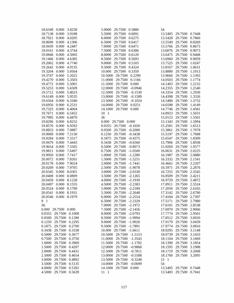
117
18.6349 0.000 3.8258 18.7138 0.000 3.9188 18.7921 0.000 4.0205 18.8690 0.000 4.1306 18.9439 0.000 4.2487 19.0161 0.000 4.3744 19.0846 0.000 4.5065 19.1466 0.000 4.6385 19.2062 0.000 4.7740 19.2642 0.000 4.9135 19.3204 0.000 5.0564 19.3747 0.000 5.2022 19.4270 0.000 5.3503 19.4772 0.000 5.5001 19.5253 0.000 5.6509 19.5712 0.000 5.8023 19.6149 0.000 5.9535 19.6564 0.000 6.1040 19.6956 0.000 6.2531 19.7325 0.000 6.4004 19.7671 0.000 6.5452 19.7995 0.000 6.6870 19.8296 0.000 6.8252 19.8576 0.000 6.9592 19.8833 0.000 7.0887 19.9069 0.000 7.2130 19.9284 0.000 7.3317 19.9479 0.000 7.4443 19.9654 0.000 7.5505 19.9811 0.000 7.6497 19.9950 0.000 7.7417 20.0072 0.000 7.8261 20.0178 0.000 7.9024 20.0269 0.000 7.9705 20.0345 0.000 8.0301 20.0408 0.000 8.0809 20.0459 0.000 8.1228 20.0497 0.000 8.1555 20.0524 0.000 8.1790 20.0541 0.000 8.1931 20.0546 0.000 8.1979 9 1 36 0.000 29.7500 0.000 0.0355 29.7500 0.1008 0.0500 29.7500 0.1280 0.1250 29.7500 0.2295 0.1875 29.7500 0.2700 0.3438 29.7500 0.3338 0.5000 29.7500 0.3677 0.7500 29.7500 0.3750 1.0000 29.7500 0.3969 1.5000 29.7500 0.4207 2.0000 29.7500 0.4431 2.5000 29.7500 0.4654 3.0000 29.7500 0.4892 3.5000 29.7500 0.5135 4.0000 29.7500 0.5392 4.5000 29.7500 0.5639
5.0000 29.7500 0.5880 5.5000 29.7500 0.6091 6.0000 29.7500 0.6275 6.5000 29.7500 0.6417 7.0000 29.7500 0.6471 7.5000 29.7500 0.6386 8.0000 29.7500 0.6120 8.5000 29.7500 0.5693 9.0000 29.7500 0.5103 9.5000 29.7500 0.4324 10.000 29.7500 0.3359 10.5000 29.7500 0.2299 11.0000 29.7500 0.1166 11.5000 29.7500 0.000 12.0000 29.7500 -0.0946 12.5000 29.7500 -0.1530 13.0000 29.7500 -0.1589 13.5000 29.7500 -0.1024 14.0000 29.7500 0.0251 14.1000 29.7500 0.000 10 1 36 0.000 29.7500 0.000 0.0355 29.7500 -0.1650 0.0500 29.7500 -0.2000 0.1250 29.7500 -0.3438 0.1875 29.7500 -0.4375 0.3438 29.7500 -0.6560 0.5000 29.7500 -0.8073 0.7500 29.7500 -1.0500 1.0000 29.7500 -1.2280 1.5000 29.7500 -1.5251 2.0000 29.7500 -1.7441 2.5000 29.7500 -1.9078 3.0000 29.7500 -2.0330 3.5000 29.7500 -2.1265 4.0000 29.7500 -2.1939 4.5000 29.7500 -2.2383 5.0000 29.7500 -2.2599 5.5000 29.7500 -2.2648 6.0000 29.7500 -2.2554 6.5000 29.7500 -2.2329 7.0000 29.7500 -2.1972 7.5000 29.7500 -2.1456 8.0000 29.7500 -2.0793 8.5000 29.7500 -1.9994 9.0000 29.7500 -1.9026 9.5000 29.7500 -1.7891 10.000 29.7500 -1.6611 10.5000 29.7500 -1.5153 11.0000 29.7500 -1.3543 11.5000 29.7500 -1.1782 12.0000 29.7500 -0.9868 12.5000 29.7500 -0.7811 13.0000 29.7500 -0.5588 13.5000 29.7500 -0.3248 14.0000 29.7500 -0.0699 14.1000 29.7500 0.000 11 1
54 13.5405 29.7500 0.7448 13.5428 29.7500 0.7860 13.5549 29.7500 0.8269 13.5766 29.7500 0.8673 13.6076 29.7500 0.9073 13.6475 29.7500 0.9468 13.6960 29.7500 0.9859 13.7525 29.7500 1.0247 13.8167 29.7500 1.0631 13.8880 29.7500 1.1013 13.9660 29.7500 1.1393 14.0503 29.7500 1.1774 14.1403 29.7500 1.2155 14.2355 29.7500 1.2540 14.3354 29.7500 1.2930 14.4398 29.7500 1.3326 14.5480 29.7500 1.3732 14.6598 29.7500 1.4149 14.7746 29.7500 1.4581 14.8923 29.7500 1.5031 15.0123 29.7500 1.5501 15.1343 29.7500 1.5994 15.2581 29.7500 1.6513 15.3861 29.7500 1.7078 15.5197 29.7500 1.7688 15.6547 29.7500 1.8309 15.7906 29.7500 1.8938 15.9269 29.7500 1.9577 16.0631 29.7500 2.0225 16.1987 29.7500 2.0880 16.3332 29.7500 2.1541 16.4662 29.7500 2.2207 16.5971 29.7500 2.2876 16.7255 29.7500 2.3545 16.8509 29.7500 2.4211 16.9729 29.7500 2.4872 17.0911 29.7500 2.5524 17.2050 29.7500 2.6165 17.3142 29.7500 2.6790 17.4184 29.7500 2.7397 17.5171 29.7500 2.7980 17.6101 29.7500 2.8538 17.6970 29.7500 2.9066 17.7774 29.7500 2.9561 17.8512 29.7500 3.0020 17.9179 29.7500 3.0439 17.9774 29.7500 3.0816 18.0295 29.7500 3.1148 18.0739 29.7500 3.1433 18.1104 29.7500 3.1669 18.1390 29.7500 3.1854 18.1595 29.7500 3.1988 18.1719 29.7500 3.2068 18.1760 29.7500 3.2095 12 1 54 13.5405 29.7500 0.7448 13.5483 29.7500 0.7041

118
13.5664 29.7500 0.6653 13.5948 29.7500 0.6285 13.6336 29.7500 0.5938 13.6826 29.7500 0.5617 13.7418 29.7500 0.5324 13.8110 29.7500 0.5064 13.8898 29.7500 0.4841 13.9779 29.7500 0.4660 14.0748 29.7500 0.4527 14.1800 29.7500 0.4447 14.2930 29.7500 0.4425 14.4130 29.7500 0.4465 14.5394 29.7500 0.4574 14.6714 29.7500 0.4754 14.8081 29.7500 0.5010 14.9486 29.7500 0.5345 15.0921 29.7500 0.5760 15.2376 29.7500 0.6258 15.3843 29.7500 0.6838 15.5312 29.7500 0.7499 15.6774 29.7500 0.8241 15.8192 29.7500 0.9045 15.9552 29.7500 0.9887 16.0900 29.7500 1.0773 16.2233 29.7500 1.1698 16.3544 29.7500 1.2657 16.4830 29.7500 1.3645 16.6087 29.7500 1.4658 16.7310 29.7500 1.5689 16.8496 29.7500 1.6733 16.9643 29.7500 1.7785 17.0747 29.7500 1.8838 17.1805 29.7500 1.9888 17.2816 29.7500 2.0927 17.3777 29.7500 2.1952 17.4687 29.7500 2.2955 17.5544 29.7500 2.3931 17.6348 29.7500 2.4874 17.7097 29.7500 2.5780 17.7790 29.7500 2.6643 17.8428 29.7500 2.7458 17.9009 29.7500 2.8220 17.9535 29.7500 2.8924 18.0004 29.7500 2.9567 18.0417 29.7500 3.0144 18.0775 29.7500 3.0651 18.1076 29.7500 3.1086 18.1323 29.7500 3.1446 18.1514 29.7500 3.1729 18.1651 29.7500 3.1932 18.1733 29.7500 3.2054 18.1760 29.7500 3.2095 13 1 54 17.8359 29.7500 3.4397 17.8074 29.7500 3.4697 17.7857 29.7500 3.5061 17.7707 29.7500 3.5487 17.7621 29.7500 3.5973
17.7599 29.7500 3.6518 17.7637 29.7500 3.7119 17.7734 29.7500 3.7774 17.7886 29.7500 3.8479 17.8091 29.7500 3.9234 17.8346 29.7500 4.0035 17.8647 29.7500 4.0882 17.8992 29.7500 4.1770 17.9376 29.7500 4.2700 17.9797 29.7500 4.3670 18.0250 29.7500 4.4677 18.0732 29.7500 4.5722 18.1239 29.7500 4.6802 18.1766 29.7500 4.7918 18.2314 29.7500 4.9077 18.2905 29.7500 5.0334 18.3530 29.7500 5.1628 18.4185 29.7500 5.2941 18.4864 29.7500 5.4270 18.5565 29.7500 5.5611 18.6283 29.7500 5.6960 18.7015 29.7500 5.8314 18.7757 29.7500 5.9669 18.8505 29.7500 6.1020 18.9255 29.7500 6.2363 19.0004 29.7500 6.3694 19.0748 29.7500 6.5010 19.1485 29.7500 6.6305 19.2209 29.7500 6.7576 19.2920 29.7500 6.8818 19.3613 29.7500 7.0027 19.4286 29.7500 7.1198 19.4936 29.7500 7.2328 19.5561 29.7500 7.3412 19.6159 29.7500 7.4447 19.6726 29.7500 7.5428 19.7262 29.7500 7.6353 19.7763 29.7500 7.7217 19.8228 29.7500 7.8017 19.8655 29.7500 7.8750 19.9042 29.7500 7.9414 19.9388 29.7500 8.0005 19.9691 29.7500 8.0523 19.9950 29.7500 8.0964 20.0163 29.7500 8.1328 20.0330 29.7500 8.1612 20.0450 29.7500 8.1815 20.0522 29.7500 8.1938 20.0546 29.7500 8.1979 14 1 54 17.8359 29.7500 3.4397 17.8704 29.7500 3.4171 17.9104 29.7500 3.4027 17.9558 29.7500 3.3966 18.0063 29.7500 3.3991 18.0619 29.7500 3.4102 18.1221 29.7500 3.4302 18.1867 29.7500 3.4592
18.2551 29.7500 3.4973 18.3268 29.7500 3.5445 18.4013 29.7500 3.6010 18.4780 29.7500 3.6668 18.5561 29.7500 3.7417 18.6349 29.7500 3.8258 18.7138 29.7500 3.9188 18.7921 29.7500 4.0205 18.8690 29.7500 4.1306 18.9439 29.7500 4.2487 19.0161 29.7500 4.3744 19.0846 29.7500 4.5065 19.1466 29.7500 4.6385 19.2062 29.7500 4.7740 19.2642 29.7500 4.9135 19.3204 29.7500 5.0564 19.3747 29.7500 5.2022 19.4270 29.7500 5.3503 19.4772 29.7500 5.5001 19.5253 29.7500 5.6509 19.5712 29.7500 5.8023 19.6149 29.7500 5.9535 19.6564 29.7500 6.1040 19.6956 29.7500 6.2531 19.7325 29.7500 6.4004 19.7671 29.7500 6.5452 19.7995 29.7500 6.6870 19.8296 29.7500 6.8252 19.8576 29.7500 6.9592 19.8833 29.7500 7.0887 19.9069 29.7500 7.2130 19.9284 29.7500 7.3317 19.9479 29.7500 7.4443 19.9654 29.7500 7.5505 19.9811 29.7500 7.6497 19.9950 29.7500 7.7417 20.0072 29.7500 7.8261 20.0178 29.7500 7.9024 20.0269 29.7500 7.9705 20.0345 29.7500 8.0301 20.0408 29.7500 8.0809 20.0459 29.7500 8.1228 20.0497 29.7500 8.1555 20.0524 29.7500 8.1790 20.0541 29.7500 8.1931 20.0546 29.7500 8.1979 15 1 2 0.000 0.000 0.000 0.000 29.7500 0.000 16 1 2 14.1000 0.000 0.000 14.1000 29.7500 0.000 17 1 2 13.5405 0.000 0.7448 13.5405 29.7500 0.7448 18 1

119
2 18.1760 0.000 3.2095 18.1760 29.7500 3.2095 19 1 2 17.8359 0.000 3.4397 17.8359 29.7500 3.4397 20 1 2 20.0546 0.000 8.1979 20.0546 29.7500 8.1979 21 1 41 21.3500 29.7500 -13.7000 15.0000 29.7500 -13.7000 10.000 29.7500 -13.7000 9.0000 29.7500 -13.7000 7.9500 29.7500 -13.7000 6.9500 29.7500 -13.2500 6.4500 29.7500 -12.9000 5.9000 29.7500 -12.3500 4.8000 29.7500 -11.0800 1.2000 29.7500 -6.6100 0.2000 29.7500 -5.1800 -0.3500 29.7500 -4.3000 -0.6800 29.7500 -3.7500 -0.9200 29.7500 -3.3500 -1.1800 29.7500 -2.7300 -1.3500 29.7500 -2.3500 -1.5000 29.7500 -1.9500 -1.6500 29.7500 -1.5500 -1.8600 29.7500 -1.0500 -2.0000 29.7500 -0.6200 -2.0600 29.7500 0.000 -2.0000 29.7500 0.6200 -1.8600 29.7500 1.0500 -1.6500 29.7500 1.5500 -1.5000 29.7500 1.9500 -1.3500 29.7500 2.3500 -1.1800 29.7500 2.7300 -0.9200 29.7500 3.3500 -0.6800 29.7500 3.7500 -0.3500 29.7500 4.3000 0.2000 29.7500 5.1800 1.2000 29.7500 6.6100 4.8000 29.7500 11.0800 5.9000 29.7500 12.3500 6.4500 29.7500 12.9000 6.9500 29.7500 13.2500 7.9500 29.7500 13.7000 9.0000 29.7500 13.7000 10.000 29.7500 13.7000 15.0000 29.7500 13.7000 21.3500 29.7500 13.7000 22 1 41 21.3500 30.000 -13.7000 15.0000 30.000 -13.7000 10.000 30.000 -13.7000
9.0000 30.000 -13.7000 7.9500 30.000 -13.7000 6.9500 30.000 -13.2500 6.4500 30.000 -12.9000 5.9000 30.000 -12.3500 4.8000 30.000 -11.0800 1.2000 30.000 -6.6100 0.2000 30.000 -5.1800 -0.3500 30.000 -4.3000 -0.6800 30.000 -3.7500 -0.9200 30.000 -3.3500 -1.1800 30.000 -2.7300 -1.3500 30.000 -2.3500 -1.5000 30.000 -1.9500 -1.6500 30.000 -1.5500 -1.8600 30.000 -1.0500 -2.0000 30.000 -0.6200 -2.0600 30.000 0.000 -2.0000 30.000 0.6200 -1.8600 30.000 1.0500 -1.6500 30.000 1.5500 -1.5000 30.000 1.9500 -1.3500 30.000 2.3500 -1.1800 30.000 2.7300 -0.9200 30.000 3.3500 -0.6800 30.000 3.7500 -0.3500 30.000 4.3000 0.2000 30.000 5.1800 1.2000 30.000 6.6100 4.8000 30.000 11.0800 5.9000 30.000 12.3500 6.4500 30.000 12.9000 6.9500 30.000 13.2500 7.9500 30.000 13.7000 9.0000 30.000 13.7000 10.000 30.000 13.7000 15.0000 30.000 13.7000 21.3500 30.000 13.7000 23 1 2 21.3500 29.7500 13.7 21.3500 29.7500 -13.7 24 1 2 21.3500 30.000 13.7 21.3500 30.000 -13.7 25 1 2 21.3500 29.7500 13.7 21.3500 30.000 13.7 26 1 2 21.3500 29.7500 -13.7 21.3500 30.000 -13.7 Surfaces 1 1 2 2 -140.000 0.000 -260.000 380.000 0.000 -260.000
-140.000 0.000 260.000 380.000 0.000 260.000 2 1 21 21 -123.0000 0.000 0.000 -121.7700 0.000 24.5680 -116.8500 0.000 54.6612 -107.0100 0.000 87.2439 -89.7900 0.000 123.4354 -68.8800 0.000 153.9419 -39.3600 0.000 184.8124 -7.3800 0.000 208.6080 29.5200 0.000 227.5475 71.3400 0.000 240.5142 123.0000 0.000 246.0000 174.6600 0.000 240.5142 216.4800 0.000 227.5475 253.3800 0.000 208.6080 285.3600 0.000 184.8124 314.8800 0.000 153.9419 335.7900 0.000 123.4354 353.0100 0.000 87.2439 362.8500 0.000 54.6612 367.7700 0.000 24.5680 369.0000 0.000 0.000 -123.0000 0.000 0.000 -121.7700 3.8435 24.2679 -116.8500 8.5511 53.9896 -107.010 13.6479 86.1689 -89.790 19.3096 121.9151 -68.880 24.0818 152.0477 -39.360 28.9108 182.5369 -7.3800 32.6334 206.0398 29.5200 35.5961 224.7456 71.3400 37.6247 237.5524 123.000 38.4828 242.9717 174.660 37.6247 237.5524 216.480 35.5961 224.7456 253.380 32.6334 206.0398 285.360 28.9108 182.5369 314.880 24.0818 152.0477 335.790 19.3096 121.9151 353.0100 13.6479 86.1689 362.8500 8.5511 53.9896 367.7700 3.8435 24.2679 369.0000 0.000 0.000 -123.0000 0.000 0.000 -121.7700 7.5923 23.3675 -116.850 16.8916 51.9872 -107.010 26.9597 82.9733 -89.7900 38.1438 117.3937 -68.880 47.5706 146.4069 -39.360 57.1098 175.7670 -7.3800 64.4632 198.3965 29.5200 70.3157 216.4087 71.3400 74.3230 228.7431 123.000 76.0181 233.9608 174.660 74.3230 228.7431 216.480 70.3157 216.4087

120
253.380 64.4632 198.3965 285.360 57.1098 175.7670 314.880 47.5706 146.4069 335.790 38.1438 117.3937 353.0100 26.9597 82.9733 362.8500 16.8916 51.9872 367.7700 7.5923 23.3675 369.0000 0.000 0.000 -123.0000 0.000 0.000 -121.770 11.1542 21.8915 -116.850 24.8162 48.7055 -107.010 39.6076 77.7335 -89.790 56.0387 109.9817 -68.880 69.8880 137.1622 -39.360 83.9025 164.6675 -7.3800 94.7057 185.8702 29.520 103.3039 202.7458 71.340 109.1912 214.3004 123.00 111.6816 219.1885 174.660 109.1912 214.3004 216.480 103.3039 202.7458 253.380 94.7057 185.8702 285.360 83.9025 164.6675 314.880 69.8880 137.1622 335.790 56.0387 109.9817 353.0100 39.6076 77.7335 362.8500 24.8162 48.7055 367.7700 11.1542 21.8915 369.0000 0.000 0.000 -123.0000 0.000 0.000 -121.770 14.4414 19.8768 -116.850 32.1297 44.2234 -107.010 51.2803 70.5823 -89.7900 72.5537 99.8612 -68.880 90.4846 124.5424 -39.360 108.6293 149.5163 -7.380 122.6163 168.7658 29.520 133.7485 184.0892 71.340 141.3708 194.5811 123.000 144.5951 199.0189 174.660 141.3708 194.5811 216.480 133.7485 184.0892 253.380 122.6163 168.7658 285.360 108.6293 149.5163 314.880 90.4846 124.5424 335.7900 72.5537 99.8612 353.0100 51.2803 70.5823 362.8500 32.1297 44.2234 367.7700 14.4414 19.8768 369.0000 0.000 0.000 -123.0000 0.000 0.000 -121.770 17.3731 17.3725 -116.850 38.6521 38.6515 -107.010 61.6903 61.6894 -89.7900 87.2823 87.2833 -68.880 108.8532 108.8525 -39.360 130.6813 130.6826 -7.3800 147.5076 147.5090 29.5200 160.8997 160.8988
71.3400 170.0694 170.0696 123.000 173.9482 173.9491 174.660 170.0694 170.0696 216.480 160.8997 160.8988 253.380 147.5076 147.5090 285.360 130.6813 130.6826 314.880 108.8532 108.8525 335.7900 87.2823 87.2833 353.0100 61.6903 61.6894 362.8500 38.6521 38.6515 367.7700 17.3731 17.3725 369.0000 0.000 0.000 -123.0000 0.000 0.000 -121.770 19.8769 14.4427 -116.850 44.2228 32.1301 -107.010 70.5813 51.2812 -89.7900 99.8617 72.5528 -68.880 124.5414 90.4837 -39.360 149.5154 108.6287 -7.3800 168.7669 122.6162 29.520 184.0890 133.7477 71.340 194.5802 141.3713 123.000 199.0181 144.5963 174.660 194.5802 141.3713 216.480 184.0890 133.7477 253.380 168.7669 122.6162 285.360 149.5154 108.6287 314.880 124.5414 90.4837 335.7900 99.8617 72.5528 353.0100 70.5813 51.2812 362.8500 44.2228 32.1301 367.7700 19.8769 14.4427 369.0000 0.000 0.000 -123.0000 0.000 0.000 -121.770 21.8913 11.1536 -116.850 48.7045 24.8165 -107.010 77.7343 39.6085 -89.7900 109.9821 56.0388 -68.8800 137.1630 69.8886 -39.3600 164.6680 83.9032 -7.3800 185.8705 94.7051 29.5200 202.7455 103.3052 71.3400 214.2999 109.1920 123.000 219.1875 111.6815 174.660 214.2999 109.1920 216.480 202.7455 103.3052 253.380 185.8705 94.7051 285.360 164.6680 83.9032 314.880 137.1630 69.8886 335.790 109.9821 56.0388 353.0100 77.7343 39.6085 362.8500 48.7045 24.8165 367.7700 21.8913 11.1536 369.0000 0.000 0.000 -123.0000 0.000 0.000 -121.7700 23.3667 7.5916 -116.850 51.9870 16.8928 -107.010 82.9733 26.9591 -89.7900 117.3945 38.1448
-68.880 146.4073 47.5715 -39.360 175.7660 57.1089 -7.3800 198.3974 64.4643 29.5200 216.4097 70.3166 71.3400 228.7428 74.3240 123.000 233.9598 76.0189 174.660 228.7428 74.3240 216.480 216.4097 70.3166 253.380 198.3974 64.4643 285.360 175.7660 57.1089 314.880 146.4073 47.5715 335.790 117.3945 38.1448 353.0100 82.9733 26.9591 362.8500 51.9870 16.8928 367.7700 23.3667 7.5916 369.0000 0.000 0.000 -123.0000 0.000 0.000 -121.7700 24.2667 3.8425 -116.8500 53.9894 8.5510 -107.010 86.1692 13.6481 -89.7900 121.9162 19.3110 -68.880 152.0465 24.0809 -39.360 182.5360 28.9099 -7.3800 206.0391 32.6344 29.5200 224.7452 35.5962 71.3400 237.5534 37.6257 123.000 242.9713 38.4842 174.660 237.5534 37.6257 216.480 224.7452 35.5962 253.380 206.0391 32.6344 285.360 182.5360 28.9099 314.880 152.0465 24.0809 335.790 121.9162 19.3110 353.0100 86.1692 13.6481 362.8500 53.9894 8.5510 367.7700 24.2667 3.8425 369.0000 0.000 0.000 -123.0000 0.000 0.000 -121.7700 24.5692 0.000 -116.8500 54.6624 0.000 -107.0100 87.2433 0.000 -89.7900 123.4359 0.000 -68.8800 153.9418 0.000 -39.3600 184.8113 0.000 -7.3800 208.6074 0.000 29.5200 227.5467 0.000 71.3400 240.5145 0.000 123.0000 246.0000 0.000 174.6600 240.5145 0.000 216.4800 227.5467 0.000 253.3800 208.6074 0.000 285.3600 184.8113 0.000 314.8800 153.9418 0.000 335.7900 123.4359 0.000 353.0100 87.2433 0.000 362.8500 54.6624 0.000 367.7700 24.5692 0.000 369.0000 0.000 0.000 -123.0000 0.000 0.000

121
-121.7700 24.2667 -3.8425 -116.8500 53.9894 -8.5510 -107.010 86.1692 -13.6481 -89.790 121.9162 -19.3085 -68.880 152.0465 -24.0809 -39.360 182.5360 -28.9099 -7.3800 206.0392 -32.6319 29.520 224.7453 -35.5962 71.340 237.5535 -37.6232 123.00 242.9714 -38.4818 174.660 237.5535 -37.6232 216.480 224.7453 -35.5962 253.380 206.0392 -32.6319 285.360 182.5360 -28.9099 314.880 152.0465 -24.0809 335.790 121.9162 -19.3085 353.010 86.1692 -13.6481 362.8500 53.9894 -8.5510 367.7700 24.2667 -3.8425 369.0000 0.000 0.000 -123.0000 0.000 0.000 -121.7700 23.3667 -7.5916 -116.850 51.9871 -16.8904 -107.010 82.9734 -26.9591 -89.790 117.3946 -38.1448 -68.880 146.4074 -47.5715 -39.360 175.7661 -57.1089 -7.3800 198.3975 -64.4618 29.520 216.4099 -70.3166 71.340 228.7430 -74.3215 123.00 233.9600 -76.0189 174.66 228.7430 -74.3215 216.48 216.4099 -70.3166 253.38 198.3975 -64.4618 285.36 175.7661 -57.1089 314.88 146.4074 -47.5715 335.79 117.3946 -38.1448 353.01 82.9734 -26.9591 362.85 51.9871 -16.8904 367.77 23.3667 -7.5916 369.00 0.000 0.000 -123.0000 0.000 0.000 -121.77 21.8914 -11.1536 -116.85 48.7046 -24.8165 -107.01 77.7345 -39.6085 -89.790 109.9823 -56.0388 -68.880 137.1632 -69.8886 -39.360 164.6683 -83.9032 -7.3800 185.8707 -94.7051 29.520 202.7458 -103.3028 71.340 214.3002 -109.1920 123.0 219.1878 -111.6815 174.66 214.3002 -109.1920 216.48 202.7458 -103.3028 253.38 185.8707 -94.7051 285.36 164.6683 -83.9032 314.88 137.1632 -69.8886 335.79 109.9823 -56.0388 353.010 77.7345 -39.6085
362.850 48.7046 -24.8165 367.770 21.8914 -11.1536 369.0000 0.000 0.000 -123.0000 0.000 0.000 -121.770 19.8770 -14.4402 -116.850 44.2229 -32.1301 -107.010 70.5814 -51.2812 -89.7900 99.8619 -72.5528 -68.880 124.5417 -90.4837 -39.36 149.5157 -108.6287 -7.380 168.7672 -122.6162 29.520 184.0894 -133.7477 71.340 194.5806 -141.3713 123.00 199.0184 -144.5939 174.66 194.5806 -141.3713 216.48 184.0894 -133.7477 253.38 168.7672 -122.6162 285.36 149.5157 -108.6287 314.88 124.5417 -90.4837 335.79 99.8619 -72.5528 353.010 70.5814 -51.2812 362.850 44.2229 -32.1301 367.770 19.8770 -14.4402 369.0000 0.000 0.000 -123.0000 0.000 0.000 -121.770 17.3731 -17.3725 -116.850 38.6522 -38.6515 -107.010 61.6905 -61.6894 -89.7900 87.2825 -87.2833 -68.88 108.8535 -108.8525 -39.36 130.6816 -130.6801 -7.380 147.5080 -147.5065 29.520 160.9001 -160.8988 71.340 170.0698 -170.0696 123.00 173.9486 -173.9491 174.66 170.0698 -170.0696 216.48 160.9001 -160.8988 253.38 147.5080 -147.5065 285.36 130.6816 -130.6801 314.88 108.8535 -108.8525 335.79 87.2825 -87.2833 353.010 61.6905 -61.6894 362.850 38.6522 -38.6515 367.770 17.3731 -17.3725 369.0000 0.000 0.000 -123.0000 0.000 0.000 -121.770 14.4415 -19.8768 -116.850 32.1298 -44.2234 -107.010 51.2805 -70.5823 -89.7900 72.5540 -99.8612 -68.880 90.4850 -124.5424 -39.36 108.6297 -149.5163 -7.380 122.6167 -168.7658 29.520 133.7490 -184.0892 71.340 141.3713 -194.5811 123.00 144.5956 -199.0189 174.66 141.3713 -194.5811 216.48 133.7490 -184.0892 253.38 122.6167 -168.7658
285.36 108.6297 -149.5163 314.88 90.4850 -124.5424 335.790 72.5540 -99.8612 353.010 51.2805 -70.5823 362.850 32.1298 -44.2234 367.7700 14.4415 -19.8768 369.0000 0.000 0.000 -123.0000 0.000 0.000 -121.770 11.1542 -21.8915 -116.850 24.8163 -48.7055 -107.010 39.6078 -77.7335 -89.790 56.0390 -109.9817 -68.880 69.8884 -137.1622 -39.360 83.9030 -164.6675 -7.3800 94.7062 -185.8702 29.52 103.3045 -202.7458 71.34 109.1918 -214.3004 123.0 111.6822 -219.1885 174.66 109.1918 -214.3004 216.48 103.3045 -202.7458 253.38 94.7062 -185.8702 285.36 83.9030 -164.6675 314.88 69.8884 -137.1622 335.79 56.0390 -109.9817 353.01 39.6078 -77.7335 362.850 24.8163 -48.7055 367.770 11.1542 -21.8915 369.0000 0.000 0.000 -123.0000 0.000 0.000 -121.7700 7.5924 -23.3675 -116.850 16.8917 -51.9872 -107.010 26.9599 -82.9733 -89.790 38.1441 -117.3937 -68.880 47.5710 -146.4069 -39.360 57.1103 -175.7670 -7.3800 64.4637 -198.3965 29.520 70.3163 -216.4087 71.340 74.3236 -228.7431 123.00 76.0187 -233.9608 174.66 74.3236 -228.7431 216.48 70.3163 -216.4087 253.38 64.4637 -198.3965 285.36 57.1103 -175.7670 314.88 47.5710 -146.4069 335.79 38.1441 -117.3937 353.010 26.9599 -82.9733 362.850 16.8917 -51.9872 367.7700 7.5924 -23.3675 369.0000 0.000 0.000 -123.0000 0.000 0.000 -121.7700 3.8435 -24.2679 -116.8500 8.5512 -53.9896 -107.010 13.6481 -86.1689 -89.790 19.3099 -121.9151 -68.880 24.0822 -152.0452 -39.360 28.9113 -182.5369 -7.3800 32.6339 -206.0398 29.520 35.5967 -224.7456 71.340 37.6254 -237.5524

122
123.00 38.4835 -242.9717 174.66 37.6254 -237.5524 216.48 35.5967 -224.7456 253.38 32.6339 -206.0398 285.36 28.9113 -182.5369 314.88 24.0822 -152.0452 335.79 19.3099 -121.9151 353.010 13.6481 -86.1689 362.8500 8.5512 -53.9896 367.7700 3.8435 -24.2679 369.0000 0.000 0.000 -123.0000 0.000 0.000 -121.7700 0.000 -24.5680 -116.8500 0.000 -54.6612 -107.0100 0.000 -87.2439 -89.7900 0.000 -123.4354 -68.8800 0.000 -153.9419 -39.3600 0.000 -184.8124 -7.3800 0.000 -208.6080 29.5200 0.000 -227.5475 71.3400 0.000 -240.5142 123.0000 0.000 -246.0000 174.6600 0.000 -240.5142 216.4800 0.000 -227.5475 253.3800 0.000 -208.6080 285.3600 0.000 -184.8124 314.8800 0.000 -153.9419 335.7900 0.000 -123.4354 353.0100 0.000 -87.2439 362.8500 0.000 -54.6612 367.7700 0.000 -24.5680 369.0000 0.000 0.000 3 1 36 2 0.000 0.000 0.000 0.0355 0.000 0.1008 0.0500 0.000 0.1280 0.1250 0.000 0.2295 0.1875 0.000 0.2700 0.3438 0.000 0.3338 0.5000 0.000 0.3677 0.7500 0.000 0.3750 1.0000 0.000 0.3969 1.5000 0.000 0.4207 2.0000 0.000 0.4431 2.5000 0.000 0.4654 3.0000 0.000 0.4892 3.5000 0.000 0.5135 4.0000 0.000 0.5392 4.5000 0.000 0.5639 5.0000 0.000 0.5880 5.5000 0.000 0.6091 6.0000 0.000 0.6275 6.5000 0.000 0.6417 7.0000 0.000 0.6471 7.5000 0.000 0.6386 8.0000 0.000 0.6120 8.5000 0.000 0.5693 9.0000 0.000 0.5103
9.5000 0.000 0.4324 10.000 0.000 0.3359 10.5000 0.000 0.2299 11.0000 0.000 0.1166 11.5000 0.000 0.000 12.0000 0.000 -0.0946 12.5000 0.000 -0.1530 13.0000 0.000 -0.1589 13.5000 0.000 -0.1024 14.0000 0.000 0.0251 14.1000 0.000 0.000 0.000 29.7500 0.000 0.0355 29.7500 0.1008 0.0500 29.7500 0.1280 0.1250 29.7500 0.2295 0.1875 29.7500 0.2700 0.3438 29.7500 0.3338 0.5000 29.7500 0.3677 0.7500 29.7500 0.3750 1.0000 29.7500 0.3969 1.5000 29.7500 0.4207 2.0000 29.7500 0.4431 2.5000 29.7500 0.4654 3.0000 29.7500 0.4892 3.5000 29.7500 0.5135 4.0000 29.7500 0.5392 4.5000 29.7500 0.5639 5.0000 29.7500 0.5880 5.5000 29.7500 0.6091 6.0000 29.7500 0.6275 6.5000 29.7500 0.6417 7.0000 29.7500 0.6471 7.5000 29.7500 0.6386 8.0000 29.7500 0.6120 8.5000 29.7500 0.5693 9.0000 29.7500 0.5103 9.5000 29.7500 0.4324 10.000 29.7500 0.3359 10.5000 29.7500 0.2299 11.0000 29.7500 0.1166 11.5000 29.7500 0.000 12.0000 29.7500 -0.0946 12.5000 29.7500 -0.1530 13.0000 29.7500 -0.1589 13.5000 29.7500 -0.1024 14.0000 29.7500 0.0251 14.1000 29.7500 0.000 4 1 36 2 0.000 0.000 0.000 0.0355 0.000 -0.1650 0.0500 0.000 -0.2000 0.1250 0.000 -0.3438 0.1875 0.000 -0.4375 0.3438 0.000 -0.6560 0.5000 0.000 -0.8073 0.7500 0.000 -1.0500 1.0000 0.000 -1.2280 1.5000 0.000 -1.5251
2.0000 0.000 -1.7441 2.5000 0.000 -1.9078 3.0000 0.000 -2.0330 3.5000 0.000 -2.1265 4.0000 0.000 -2.1939 4.5000 0.000 -2.2383 5.0000 0.000 -2.2599 5.5000 0.000 -2.2648 6.0000 0.000 -2.2554 6.5000 0.000 -2.2329 7.0000 0.000 -2.1972 7.5000 0.000 -2.1456 8.0000 0.000 -2.0793 8.5000 0.000 -1.9994 9.0000 0.000 -1.9026 9.5000 0.000 -1.7891 10.000 0.000 -1.6611 10.5000 0.000 -1.5153 11.0000 0.000 -1.3543 11.5000 0.000 -1.1782 12.0000 0.000 -0.9868 12.5000 0.000 -0.7811 13.0000 0.000 -0.5588 13.5000 0.000 -0.3248 14.0000 0.000 -0.0699 14.1000 0.000 0.000 0.000 29.7500 0.000 0.0355 29.7500 -0.1650 0.0500 29.7500 -0.2000 0.1250 29.7500 -0.3438 0.1875 29.7500 -0.4375 0.3438 29.7500 -0.6560 0.5000 29.7500 -0.8073 0.7500 29.7500 -1.0500 1.0000 29.7500 -1.2280 1.5000 29.7500 -1.5251 2.0000 29.7500 -1.7441 2.5000 29.7500 -1.9078 3.0000 29.7500 -2.0330 3.5000 29.7500 -2.1265 4.0000 29.7500 -2.1939 4.5000 29.7500 -2.2383 5.0000 29.7500 -2.2599 5.5000 29.7500 -2.2648 6.0000 29.7500 -2.2554 6.5000 29.7500 -2.2329 7.0000 29.7500 -2.1972 7.5000 29.7500 -2.1456 8.0000 29.7500 -2.0793 8.5000 29.7500 -1.9994 9.0000 29.7500 -1.9026 9.5000 29.7500 -1.7891 10.000 29.7500 -1.6611 10.5000 29.7500 -1.5153 11.0000 29.7500 -1.3543 11.5000 29.7500 -1.1782 12.0000 29.7500 -0.9868 12.5000 29.7500 -0.7811 13.0000 29.7500 -0.5588

123
13.5000 29.7500 -0.3248 14.0000 29.7500 -0.0699 14.1000 29.7500 0.000 5 1 54 2 13.5405 0.000 0.7448 13.5428 0.000 0.7860 13.5549 0.000 0.8269 13.5766 0.000 0.8673 13.6076 0.000 0.9073 13.6475 0.000 0.9468 13.6960 0.000 0.9859 13.7525 0.000 1.0247 13.8167 0.000 1.0631 13.8880 0.000 1.1013 13.9660 0.000 1.1393 14.0503 0.000 1.1774 14.1403 0.000 1.2155 14.2355 0.000 1.2540 14.3354 0.000 1.2930 14.4398 0.000 1.3326 14.5480 0.000 1.3732 14.6598 0.000 1.4149 14.7746 0.000 1.4581 14.8923 0.000 1.5031 15.0123 0.000 1.5501 15.1343 0.000 1.5994 15.2581 0.000 1.6513 15.3861 0.000 1.7078 15.5197 0.000 1.7688 15.6547 0.000 1.8309 15.7906 0.000 1.8938 15.9269 0.000 1.9577 16.0631 0.000 2.0225 16.1987 0.000 2.0880 16.3332 0.000 2.1541 16.4662 0.000 2.2207 16.5971 0.000 2.2876 16.7255 0.000 2.3545 16.8509 0.000 2.4211 16.9729 0.000 2.4872 17.0911 0.000 2.5524 17.2050 0.000 2.6165 17.3142 0.000 2.6790 17.4184 0.000 2.7397 17.5171 0.000 2.7980 17.6101 0.000 2.8538 17.6970 0.000 2.9066 17.7774 0.000 2.9561 17.8512 0.000 3.0020 17.9179 0.000 3.0439 17.9774 0.000 3.0816 18.0295 0.000 3.1148 18.0739 0.000 3.1433 18.1104 0.000 3.1669 18.1390 0.000 3.1854 18.1595 0.000 3.1988 18.1719 0.000 3.2068 18.1760 0.000 3.2095
13.5405 29.7500 0.7448 13.5428 29.7500 0.7860 13.5549 29.7500 0.8269 13.5766 29.7500 0.8673 13.6076 29.7500 0.9073 13.6475 29.7500 0.9468 13.6960 29.7500 0.9859 13.7525 29.7500 1.0247 13.8167 29.7500 1.0631 13.8880 29.7500 1.1013 13.9660 29.7500 1.1393 14.0503 29.7500 1.1774 14.1403 29.7500 1.2155 14.2355 29.7500 1.2540 14.3354 29.7500 1.2930 14.4398 29.7500 1.3326 14.5480 29.7500 1.3732 14.6598 29.7500 1.4149 14.7746 29.7500 1.4581 14.8923 29.7500 1.5031 15.0123 29.7500 1.5501 15.1343 29.7500 1.5994 15.2581 29.7500 1.6513 15.3861 29.7500 1.7078 15.5197 29.7500 1.7688 15.6547 29.7500 1.8309 15.7906 29.7500 1.8938 15.9269 29.7500 1.9577 16.0631 29.7500 2.0225 16.1987 29.7500 2.0880 16.3332 29.7500 2.1541 16.4662 29.7500 2.2207 16.5971 29.7500 2.2876 16.7255 29.7500 2.3545 16.8509 29.7500 2.4211 16.9729 29.7500 2.4872 17.0911 29.7500 2.5524 17.2050 29.7500 2.6165 17.3142 29.7500 2.6790 17.4184 29.7500 2.7397 17.5171 29.7500 2.7980 17.6101 29.7500 2.8538 17.6970 29.7500 2.9066 17.7774 29.7500 2.9561 17.8512 29.7500 3.0020 17.9179 29.7500 3.0439 17.9774 29.7500 3.0816 18.0295 29.7500 3.1148 18.0739 29.7500 3.1433 18.1104 29.7500 3.1669 18.1390 29.7500 3.1854 18.1595 29.7500 3.1988 18.1719 29.7500 3.2068 18.1760 29.7500 3.2095 6 1 54 2 13.5405 0.000 0.7448 13.5483 0.000 0.7041 13.5664 0.000 0.6653
13.5948 0.000 0.6285 13.6336 0.000 0.5938 13.6826 0.000 0.5617 13.7418 0.000 0.5324 13.8110 0.000 0.5064 13.8898 0.000 0.4841 13.9779 0.000 0.4660 14.0748 0.000 0.4527 14.1800 0.000 0.4447 14.2930 0.000 0.4425 14.4130 0.000 0.4465 14.5394 0.000 0.4574 14.6714 0.000 0.4754 14.8081 0.000 0.5010 14.9486 0.000 0.5345 15.0921 0.000 0.5760 15.2376 0.000 0.6258 15.3843 0.000 0.6838 15.5312 0.000 0.7499 15.6774 0.000 0.8241 15.8192 0.000 0.9045 15.9552 0.000 0.9887 16.0900 0.000 1.0773 16.2233 0.000 1.1698 16.3544 0.000 1.2657 16.4830 0.000 1.3645 16.6087 0.000 1.4658 16.7310 0.000 1.5689 16.8496 0.000 1.6733 16.9643 0.000 1.7785 17.0747 0.000 1.8838 17.1805 0.000 1.9888 17.2816 0.000 2.0927 17.3777 0.000 2.1952 17.4687 0.000 2.2955 17.5544 0.000 2.3931 17.6348 0.000 2.4874 17.7097 0.000 2.5780 17.7790 0.000 2.6643 17.8428 0.000 2.7458 17.9009 0.000 2.8220 17.9535 0.000 2.8924 18.0004 0.000 2.9567 18.0417 0.000 3.0144 18.0775 0.000 3.0651 18.1076 0.000 3.1086 18.1323 0.000 3.1446 18.1514 0.000 3.1729 18.1651 0.000 3.1932 18.1733 0.000 3.2054 18.1760 0.000 3.2095 13.5405 29.7500 0.7448 13.5483 29.7500 0.7041 13.5664 29.7500 0.6653 13.5948 29.7500 0.6285 13.6336 29.7500 0.5938 13.6826 29.7500 0.5617 13.7418 29.7500 0.5324 13.8110 29.7500 0.5064

124
13.8898 29.7500 0.4841 13.9779 29.7500 0.4660 14.0748 29.7500 0.4527 14.1800 29.7500 0.4447 14.2930 29.7500 0.4425 14.4130 29.7500 0.4465 14.5394 29.7500 0.4574 14.6714 29.7500 0.4754 14.8081 29.7500 0.5010 14.9486 29.7500 0.5345 15.0921 29.7500 0.5760 15.2376 29.7500 0.6258 15.3843 29.7500 0.6838 15.5312 29.7500 0.7499 15.6774 29.7500 0.8241 15.8192 29.7500 0.9045 15.9552 29.7500 0.9887 16.0900 29.7500 1.0773 16.2233 29.7500 1.1698 16.3544 29.7500 1.2657 16.4830 29.7500 1.3645 16.6087 29.7500 1.4658 16.7310 29.7500 1.5689 16.8496 29.7500 1.6733 16.9643 29.7500 1.7785 17.0747 29.7500 1.8838 17.1805 29.7500 1.9888 17.2816 29.7500 2.0927 17.3777 29.7500 2.1952 17.4687 29.7500 2.2955 17.5544 29.7500 2.3931 17.6348 29.7500 2.4874 17.7097 29.7500 2.5780 17.7790 29.7500 2.6643 17.8428 29.7500 2.7458 17.9009 29.7500 2.8220 17.9535 29.7500 2.8924 18.0004 29.7500 2.9567 18.0417 29.7500 3.0144 18.0775 29.7500 3.0651 18.1076 29.7500 3.1086 18.1323 29.7500 3.1446 18.1514 29.7500 3.1729 18.1651 29.7500 3.1932 18.1733 29.7500 3.2054 18.1760 29.7500 3.2095 7 1 54 2 17.8359 0.000 3.4397 17.8074 0.000 3.4697 17.7857 0.000 3.5061 17.7707 0.000 3.5487 17.7621 0.000 3.5973 17.7599 0.000 3.6518 17.7637 0.000 3.7119 17.7734 0.000 3.7774 17.7886 0.000 3.8479 17.8091 0.000 3.9234 17.8346 0.000 4.0035
17.8647 0.000 4.0882 17.8992 0.000 4.1770 17.9376 0.000 4.2700 17.9797 0.000 4.3670 18.0250 0.000 4.4677 18.0732 0.000 4.5722 18.1239 0.000 4.6802 18.1766 0.000 4.7918 18.2314 0.000 4.9077 18.2905 0.000 5.0334 18.3530 0.000 5.1628 18.4185 0.000 5.2941 18.4864 0.000 5.4270 18.5565 0.000 5.5611 18.6283 0.000 5.6960 18.7015 0.000 5.8314 18.7757 0.000 5.9669 18.8505 0.000 6.1020 18.9255 0.000 6.2363 19.0004 0.000 6.3694 19.0748 0.000 6.5010 19.1485 0.000 6.6305 19.2209 0.000 6.7576 19.2920 0.000 6.8818 19.3613 0.000 7.0027 19.4286 0.000 7.1198 19.4936 0.000 7.2328 19.5561 0.000 7.3412 19.6159 0.000 7.4447 19.6726 0.000 7.5428 19.7262 0.000 7.6353 19.7763 0.000 7.7217 19.8228 0.000 7.8017 19.8655 0.000 7.8750 19.9042 0.000 7.9414 19.9388 0.000 8.0005 19.9691 0.000 8.0523 19.9950 0.000 8.0964 20.0163 0.000 8.1328 20.0330 0.000 8.1612 20.0450 0.000 8.1815 20.0522 0.000 8.1938 20.0546 0.000 8.1979 17.8359 29.7500 3.4397 17.8074 29.7500 3.4697 17.7857 29.7500 3.5061 17.7707 29.7500 3.5487 17.7621 29.7500 3.5973 17.7599 29.7500 3.6518 17.7637 29.7500 3.7119 17.7734 29.7500 3.7774 17.7886 29.7500 3.8479 17.8091 29.7500 3.9234 17.8346 29.7500 4.0035 17.8647 29.7500 4.0882 17.8992 29.7500 4.1770 17.9376 29.7500 4.2700 17.9797 29.7500 4.3670 18.0250 29.7500 4.4677
18.0732 29.7500 4.5722 18.1239 29.7500 4.6802 18.1766 29.7500 4.7918 18.2314 29.7500 4.9077 18.2905 29.7500 5.0334 18.3530 29.7500 5.1628 18.4185 29.7500 5.2941 18.4864 29.7500 5.4270 18.5565 29.7500 5.5611 18.6283 29.7500 5.6960 18.7015 29.7500 5.8314 18.7757 29.7500 5.9669 18.8505 29.7500 6.1020 18.9255 29.7500 6.2363 19.0004 29.7500 6.3694 19.0748 29.7500 6.5010 19.1485 29.7500 6.6305 19.2209 29.7500 6.7576 19.2920 29.7500 6.8818 19.3613 29.7500 7.0027 19.4286 29.7500 7.1198 19.4936 29.7500 7.2328 19.5561 29.7500 7.3412 19.6159 29.7500 7.4447 19.6726 29.7500 7.5428 19.7262 29.7500 7.6353 19.7763 29.7500 7.7217 19.8228 29.7500 7.8017 19.8655 29.7500 7.8750 19.9042 29.7500 7.9414 19.9388 29.7500 8.0005 19.9691 29.7500 8.0523 19.9950 29.7500 8.0964 20.0163 29.7500 8.1328 20.0330 29.7500 8.1612 20.0450 29.7500 8.1815 20.0522 29.7500 8.1938 20.0546 29.7500 8.1979 8 1 54 2 17.8359 0.000 3.4397 17.8704 0.000 3.4171 17.9104 0.000 3.4027 17.9558 0.000 3.3966 18.0063 0.000 3.3991 18.0619 0.000 3.4102 18.1221 0.000 3.4302 18.1867 0.000 3.4592 18.2551 0.000 3.4973 18.3268 0.000 3.5445 18.4013 0.000 3.6010 18.4780 0.000 3.6668 18.5561 0.000 3.7417 18.6349 0.000 3.8258 18.7138 0.000 3.9188 18.7921 0.000 4.0205 18.8690 0.000 4.1306 18.9439 0.000 4.2487 19.0161 0.000 4.3744

125
19.0846 0.000 4.5065 19.1466 0.000 4.6385 19.2062 0.000 4.7740 19.2642 0.000 4.9135 19.3204 0.000 5.0564 19.3747 0.000 5.2022 19.4270 0.000 5.3503 19.4772 0.000 5.5001 19.5253 0.000 5.6509 19.5712 0.000 5.8023 19.6149 0.000 5.9535 19.6564 0.000 6.1040 19.6956 0.000 6.2531 19.7325 0.000 6.4004 19.7671 0.000 6.5452 19.7995 0.000 6.6870 19.8296 0.000 6.8252 19.8576 0.000 6.9592 19.8833 0.000 7.0887 19.9069 0.000 7.2130 19.9284 0.000 7.3317 19.9479 0.000 7.4443 19.9654 0.000 7.5505 19.9811 0.000 7.6497 19.9950 0.000 7.7417 20.0072 0.000 7.8261 20.0178 0.000 7.9024 20.0269 0.000 7.9705 20.0345 0.000 8.0301 20.0408 0.000 8.0809 20.0459 0.000 8.1228 20.0497 0.000 8.1555 20.0524 0.000 8.1790 20.0541 0.000 8.1931 20.0546 0.000 8.1979 17.8359 29.7500 3.4397 17.8704 29.7500 3.4171 17.9104 29.7500 3.4027 17.9558 29.7500 3.3966 18.0063 29.7500 3.3991 18.0619 29.7500 3.4102 18.1221 29.7500 3.4302 18.1867 29.7500 3.4592 18.2551 29.7500 3.4973 18.3268 29.7500 3.5445 18.4013 29.7500 3.6010 18.4780 29.7500 3.6668 18.5561 29.7500 3.7417 18.6349 29.7500 3.8258 18.7138 29.7500 3.9188 18.7921 29.7500 4.0205 18.8690 29.7500 4.1306 18.9439 29.7500 4.2487 19.0161 29.7500 4.3744 19.0846 29.7500 4.5065 19.1466 29.7500 4.6385 19.2062 29.7500 4.7740 19.2642 29.7500 4.9135 19.3204 29.7500 5.0564
19.3747 29.7500 5.2022 19.4270 29.7500 5.3503 19.4772 29.7500 5.5001 19.5253 29.7500 5.6509 19.5712 29.7500 5.8023 19.6149 29.7500 5.9535 19.6564 29.7500 6.1040 19.6956 29.7500 6.2531 19.7325 29.7500 6.4004 19.7671 29.7500 6.5452 19.7995 29.7500 6.6870 19.8296 29.7500 6.8252 19.8576 29.7500 6.9592 19.8833 29.7500 7.0887 19.9069 29.7500 7.2130 19.9284 29.7500 7.3317 19.9479 29.7500 7.4443 19.9654 29.7500 7.5505 19.9811 29.7500 7.6497 19.9950 29.7500 7.7417 20.0072 29.7500 7.8261 20.0178 29.7500 7.9024 20.0269 29.7500 7.9705 20.0345 29.7500 8.0301 20.0408 29.7500 8.0809 20.0459 29.7500 8.1228 20.0497 29.7500 8.1555 20.0524 29.7500 8.1790 20.0541 29.7500 8.1931 20.0546 29.7500 8.1979 9 1 2 2 -30.000 29.7500 -30.000 30.000 29.7500 -30.000 -30.000 29.7500 30.000 30.000 29.7500 30.000 10 1 2 2 -30.000 30.000 -30.000 30.000 30.000 -30.000 -30.000 30.000 30.000 30.000 30.000 30.000 11 1 2 2 21.3500 29.7500 -13.7000 21.3500 30.000 -13.7000 21.3500 29.7500 13.7000 21.3500 30.000 13.7000 12 1 41 2 21.3500 29.7500 -13.7000 15.0000 29.7500 -13.7000 10.000 29.7500 -13.7000 9.0000 29.7500 -13.7000 7.9500 29.7500 -13.7000 6.9500 29.7500 -13.2500 6.4500 29.7500 -12.9000 5.9000 29.7500 -12.3500 4.8000 29.7500 -11.0800
1.2000 29.7500 -6.6100 0.2000 29.7500 -5.1800 -0.3500 29.7500 -4.3000 -0.6800 29.7500 -3.7500 -0.9200 29.7500 -3.3500 -1.1800 29.7500 -2.7300 -1.3500 29.7500 -2.3500 -1.5000 29.7500 -1.9500 -1.6500 29.7500 -1.5500 -1.8600 29.7500 -1.0500 -2.0000 29.7500 -0.6200 -2.0600 29.7500 0.000 -2.0000 29.7500 0.6200 -1.8600 29.7500 1.0500 -1.6500 29.7500 1.5500 -1.5000 29.7500 1.9500 -1.3500 29.7500 2.3500 -1.1800 29.7500 2.7300 -0.9200 29.7500 3.3500 -0.6800 29.7500 3.7500 -0.3500 29.7500 4.3000 0.2000 29.7500 5.1800 1.2000 29.7500 6.6100 4.8000 29.7500 11.0800 5.9000 29.7500 12.3500 6.4500 29.7500 12.9000 6.9500 29.7500 13.2500 7.9500 29.7500 13.7000 9.0000 29.7500 13.7000 10.000 29.7500 13.7000 15.0000 29.7500 13.7000 21.3500 29.7500 13.7000 21.3500 30.000 -13.7000 15.0000 30.000 -13.7000 10.000 30.000 -13.7000 9.0000 30.000 -13.7000 7.9500 30.000 -13.7000 6.9500 30.000 -13.2500 6.4500 30.000 -12.9000 5.9000 30.000 -12.3500 4.8000 30.000 -11.0800 1.2000 30.000 -6.6100 0.2000 30.000 -5.1800 -0.3500 30.000 -4.3000 -0.6800 30.000 -3.7500 -0.9200 30.000 -3.3500 -1.1800 30.000 -2.7300 -1.3500 30.000 -2.3500 -1.5000 30.000 -1.9500 -1.6500 30.000 -1.5500 -1.8600 30.000 -1.0500 -2.0000 30.000 -0.6200 -2.0600 30.000 0.000 -2.0000 30.000 0.6200 -1.8600 30.000 1.0500 -1.6500 30.000 1.5500 -1.5000 30.000 1.9500 -1.3500 30.000 2.3500 -1.1800 30.000 2.7300

126
-0.9200 30.000 3.3500 -0.6800 30.000 3.7500 -0.3500 30.000 4.3000 0.2000 30.000 5.1800 1.2000 30.000 6.6100 4.8000 30.000 11.0800 5.9000 30.000 12.3500 6.4500 30.000 12.9000 6.9500 30.000 13.2500 7.9500 30.000 13.7000 9.0000 30.000 13.7000 10.000 30.000 13.7000 15.0000 30.000 13.7000 21.3500 30.000 13.7000 Mesh generation 26 12 Curves segments 1 1 1 2 2 1 3 3 1 4 4 1 5 5 1 6 6 1 7 7 1 8 8 1 9 9 1 10 10 1 11 11 1 12 12 1 13 13 1 14 14 1 15 15 1 16 16 1 17 17 1 18 18 1 19 19 1 20 20 1 21 21 1 22 22 1 23 23 1 24 24 1 25 25 1 26 26 1 Surface Regions 1 1 1 8 1 -2 -3 4 -5 6 -7 8 2 2 1 2 1 2 3 3 1 4 15 3 16 9 4 4 1 4
15 10 16 4 5 5 1 4 17 5 18 11 6 6 1 4 17 12 18 6 7 7 1 4 19 7 20 13 8 8 1 4 19 14 20 8 9 9 1 8 21 23 9 -10 11 -12 13 -14 10 10 1 2 22 24 11 11 1 4 23 26 24 25 12 12 1 4 21 25 -22 -26
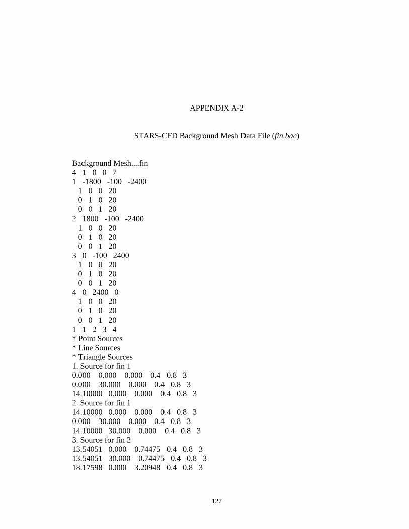
127
APPENDIX A-2
STARS-CFD Background Mesh Data File (fin.bac)
Background Mesh....fin 4 1 0 0 7 1 -1800 -100 -2400 1 0 0 20 0 1 0 20 0 0 1 20 2 1800 -100 -2400 1 0 0 20 0 1 0 20 0 0 1 20 3 0 -100 2400 1 0 0 20 0 1 0 20 0 0 1 20 4 0 2400 0 1 0 0 20 0 1 0 20 0 0 1 20 1 1 2 3 4 * Point Sources * Line Sources * Triangle Sources 1. Source for fin 1 0.000 0.000 0.000 0.4 0.8 3 0.000 30.000 0.000 0.4 0.8 3 14.10000 0.000 0.000 0.4 0.8 3 2. Source for fin 1 14.10000 0.000 0.000 0.4 0.8 3 0.000 30.000 0.000 0.4 0.8 3 14.10000 30.000 0.000 0.4 0.8 3 3. Source for fin 2 13.54051 0.000 0.74475 0.4 0.8 3 13.54051 30.000 0.74475 0.4 0.8 3 18.17598 0.000 3.20948 0.4 0.8 3

128
4. Source for fin 2 18.17598 0.000 3.20948 0.4 0.8 3 13.54051 30.000 0.74475 0.4 0.8 3 18.17598 30.000 3.20948 0.4 0.8 3 5. Source for fin 3 17.83585 0.000 3.43973 0.4 0.8 3 17.83585 30.000 3.43973 0.4 0.8 3 20.05219 0.000 8.19376 0.4 0.8 3 6. Source for fin 3 20.05219 0.000 8.19376 0.4 0.8 3 17.83585 30.000 3.43973 0.4 0.8 3 20.05219 30.000 8.19376 0.4 0.8 3 7. Source for endplate 21.00000 30.000 13.0000 0.6 0.8 5 21.00000 30.000 -13.000 0.6 0.8 5 -2.00000 30.000 0.000 0.6 0.8 5

129
APPENDIX A-3
STARS-CFD Boundary Conditions Data File (fin.bco)
Fin Boundary Condition File 12 26 Surface Regions 1 2 2 3 3 1 4 1 5 1 6 1 7 1 8 1 9 1 10 1 11 1 12 1 Curve Segments 1 0 2 0 3 4 4 4 5 4 6 4 7 4 8 4 9 4 10 4 11 4 12 4 13 4 14 4 15 0 16 1
17 0 18 1 19 0 20 1 21 1 22 1 23 1 24 1 25 1 26 1

130
APPENDIX A-4
STARS-CFD Parameter Control File (fin.cons)
&control nout = 50, nstep = 1, ncycl = 5000, nstpe = 20, cfl = 0.3, nsmth = 0, smofc = 0.2, relax = 1.0, mach = 0.434, alpha = 0.0, beta = 0.0, restart = 0, amplitude= 1.0, /
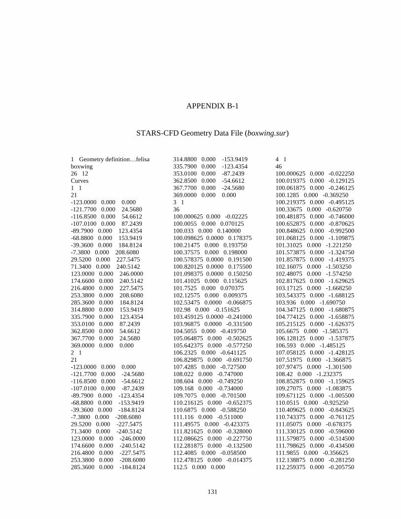
131
APPENDIX B-1
STARS-CFD Geometry Data File (boxwing.sur)
1 Geometry definition…felisa boxwing 26 12 Curves 1 1 21 -123.0000 0.000 0.000 -121.7700 0.000 24.5680 -116.8500 0.000 54.6612 -107.0100 0.000 87.2439 -89.7900 0.000 123.4354 -68.8800 0.000 153.9419 -39.3600 0.000 184.8124 -7.3800 0.000 208.6080 29.5200 0.000 227.5475 71.3400 0.000 240.5142 123.0000 0.000 246.0000 174.6600 0.000 240.5142 216.4800 0.000 227.5475 253.3800 0.000 208.6080 285.3600 0.000 184.8124 314.8800 0.000 153.9419 335.7900 0.000 123.4354 353.0100 0.000 87.2439 362.8500 0.000 54.6612 367.7700 0.000 24.5680 369.0000 0.000 0.000 2 1 21 -123.0000 0.000 0.000 -121.7700 0.000 -24.5680 -116.8500 0.000 -54.6612 -107.0100 0.000 -87.2439 -89.7900 0.000 -123.4354 -68.8800 0.000 -153.9419 -39.3600 0.000 -184.8124 -7.3800 0.000 -208.6080 29.5200 0.000 -227.5475 71.3400 0.000 -240.5142 123.0000 0.000 -246.0000 174.6600 0.000 -240.5142 216.4800 0.000 -227.5475 253.3800 0.000 -208.6080 285.3600 0.000 -184.8124
314.8800 0.000 -153.9419 335.7900 0.000 -123.4354 353.0100 0.000 -87.2439 362.8500 0.000 -54.6612 367.7700 0.000 -24.5680 369.0000 0.000 0.000 3 1 36 100.000625 0.000 -0.02225 100.0055 0.000 0.070125 100.033 0.000 0.140000 100.098625 0.0000 0.178375 100.21475 0.000 0.193750 100.37575 0.000 0.198000 100.578375 0.0000 0.191500 100.820125 0.0000 0.175500 101.098375 0.0000 0.150250 101.41025 0.000 0.115625 101.7525 0.000 0.070375 102.12575 0.000 0.009375 102.53475 0.0000 -0.066875 102.98 0.000 -0.151625 103.459125 0.0000 -0.241000 103.96875 0.0000 -0.331500 104.5055 0.000 -0.419750 105.064875 0.000 -0.502625 105.642375 0.000 -0.577250 106.2325 0.000 -0.641125 106.829875 0.000 -0.691750 107.4285 0.000 -0.727500 108.022 0.000 -0.747000 108.604 0.000 -0.749250 109.168 0.000 -0.734000 109.7075 0.000 -0.701500 110.216125 0.000 -0.652375 110.6875 0.000 -0.588250 111.116 0.000 -0.511000 111.49575 0.000 -0.423375 111.821625 0.000 -0.328000 112.086625 0.000 -0.227750 112.281875 0.000 -0.132500 112.4085 0.000 -0.058500 112.478125 0.000 -0.014375 112.5 0.000 0.000
4 1 46 100.000625 0.000 -0.022250 100.019375 0.000 -0.129125 100.061875 0.000 -0.246125 100.1285 0.000 -0.369250 100.219375 0.000 -0.495125 100.33675 0.000 -0.620750 100.481875 0.000 -0.746000 100.652875 0.000 -0.870625 100.848625 0.000 -0.992500 101.068125 0.000 -1.109875 101.31025 0.000 -1.221250 101.573875 0.000 -1.324750 101.857875 0.000 -1.419375 102.16075 0.000 -1.503250 102.48075 0.000 -1.574250 102.817625 0.000 -1.629625 103.17125 0.000 -1.668250 103.543375 0.000 -1.688125 103.936 0.000 -1.690750 104.347125 0.000 -1.680875 104.774125 0.000 -1.658875 105.215125 0.000 -1.626375 105.6675 0.000 -1.585375 106.128125 0.000 -1.537875 106.593 0.000 -1.485125 107.058125 0.000 -1.428125 107.51975 0.000 -1.366875 107.97475 0.000 -1.301500 108.42 0.000 -1.232375 108.852875 0.000 -1.159625 109.27075 0.000 -1.083875 109.671125 0.000 -1.005500 110.0515 0.000 -0.925250 110.409625 0.000 -0.843625 110.743375 0.000 -0.761125 111.05075 0.000 -0.678375 111.330125 0.000 -0.596000 111.579875 0.000 -0.514500 111.798625 0.000 -0.434500 111.9855 0.000 -0.356625 112.138875 0.000 -0.281250 112.259375 0.000 -0.205750

132
112.353125 0.000 -0.129625 112.427125 0.000 -0.061750 112.47975 0.000 -0.015750 112.5 0.000 0.000 5 1 36 112.500625 0.000 12.477750 112.5055 0.000 12.570125 112.533 0.000 12.640000 112.598625 0.000 12.678375 112.71475 0.000 12.693750 112.87575 0.000 12.698000 113.078375 0.000 12.691500 113.320125 0.000 12.675500 113.598375 0.000 12.650250 113.91025 0.000 12.615625 114.2525 0.000 12.570375 114.62575 0.000 12.509375 115.03475 0.000 12.433125 115.48 0.000 12.348375 115.959125 0.000 12.259000 116.46875 0.000 12.168500 117.0055 0.000 12.080250 117.564875 0.000 11.997375 118.142375 0.000 11.922750 118.7325 0.000 11.858875 119.329875 0.000 11.808250 119.9285 0.000 11.772500 120.522 0.000 11.753000 121.104 0.000 11.750750 121.668 0.000 11.766000 122.2075 0.000 11.798500 122.716125 0.000 11.847625 123.1875 0.000 11.911750 123.616 0.000 11.989000 123.99575 0.000 12.076625 124.321625 0.000 12.172000 124.586625 0.000 12.272250 124.781875 0.000 12.367500 124.9085 0.000 12.441500 124.978125 0.000 12.485625 125 0.000 12.500000 6 1 46 112.500625 0.000 12.477750 112.519375 0.000 12.370875 112.561875 0.000 12.253875 112.6285 0.000 12.130750 112.719375 0.000 12.004875 112.83675 0.000 11.879250 112.981875 0.000 11.754000 113.152875 0.000 11.629375 113.348625 0.000 11.507500 113.568125 0.000 11.390125 113.81025 0.000 11.278750 114.073875 0.000 11.175250 114.357875 0.000 11.080625 114.66075 0.000 10.996750 114.98075 0.000 10.925750
115.317625 0.000 10.870375 115.67125 0.000 10.831750 116.043375 0.000 10.811875 116.436 0.000 10.809250 116.847125 0.000 10.819125 117.274125 0.000 10.841125 117.715125 0.000 10.873625 118.1675 0.000 10.914625 118.628125 0.000 10.962125 119.093 0.000 11.014875 119.558125 0.000 11.071875 120.01975 0.000 11.133125 120.47475 0.000 11.198500 120.92 0.000 11.267625 121.352875 0.000 11.340375 121.77075 0.000 11.416125 122.171125 0.000 11.494500 122.5515 0.000 11.574750 122.909625 0.000 11.656375 123.243375 0.000 11.738875 123.55075 0.000 11.821625 123.830125 0.000 11.904000 124.079875 0.000 11.985500 124.298625 0.000 12.065500 124.4855 0.000 12.143375 124.638875 0.000 12.218750 124.759375 0.000 12.294250 124.853125 0.000 12.370375 124.927125 0.000 12.438250 124.97975 0.000 12.484250 125 0.000 12.500000 7 1 36 100.000625 29.7500 -0.02225 100.0055 29.7500 0.070125 100.033 29.75000 0.140000 100.098625 29.750 0.178375 100.21475 29.750 0.193750 100.37575 29.750 0.198000 100.578375 29.750 0.191500 100.820125 29.750 0.175500 101.098375 29.750 0.150250 101.41025 29.750 0.115625 101.7525 29.750 0.070375 102.12575 29.750 0.009375 102.53475 29.750 -0.066875 102.98 29.750 -0.151625 103.459125 29.750 -0.24100 103.96875 29.750 -0.331500 104.5055 29.750 -0.419750 105.064875 29.750 -0.502625 105.642375 29.750 -0.577250 106.2325 29.750 -0.641125 106.829875 29.750 -0.691750 107.4285 29.750 -0.727500 108.022 29.750 -0.747000 108.604 29.750 -0.749250 109.168 29.750 -0.734000 109.7075 29.750 -0.701500
110.216125 29.750 -0.652375 110.6875 29.750 -0.588250 111.116 29.750 -0.511000 111.49575 29.750 -0.423375 111.821625 29.750 -0.32800 112.086625 29.750 -0.22775 112.281875 29.750 -0.13250 112.4085 29.750 -0.058500 112.478125 29.750 -0.014375 112.5 29.750 0.000 8 1 46 100.000625 29.750 -0.02225 100.019375 29.750 -0.129125 100.061875 29.75 -0.246125 100.12850 29.750 -0.369250 100.219375 29.750 -0.495125 100.336750 29.750 -0.62075 100.481875 29.750 -0.74600 100.652875 29.750 -0.870625 100.848625 29.750 -0.99250 101.068125 29.750 -1.109875 101.310250 29.750 -1.22125 101.573875 29.750 -1.32475 101.857875 29.750 -1.419375 102.160750 29.750 -1.50325 102.480750 29.750 -1.57425 102.817625 29.750 -1.629625 103.171250 29.750 -1.66825 103.543375 29.750 -1.688125 103.93600 29.750 -1.69075 104.347125 29.750 -1.680875 104.774125 29.750 -1.658875 105.215125 29.750 -1.626375 105.66750 29.750 -1.585375 106.128125 29.750 -1.537875 106.593000 29.750 -1.485125 107.058125 29.750 -1.428125 107.519750 29.750 -1.366875 107.974750 29.750 -1.30150 108.420000 29.750 -1.232375 108.852875 29.750 -1.159625 109.270750 29.750 -1.083875 109.671125 29.750 -1.00550 110.051500 29.750 -0.92525 110.409625 29.750 -0.843625 110.743375 29.750 -0.761125 111.050750 29.750 -0.678375 111.330125 29.750 -0.596000 111.579875 29.750 -0.514500 111.798625 29.750 -0.434500 111.985500 29.750 -0.356625 112.138875 29.750 -0.281250 112.259375 29.750 -0.205750 112.353125 29.750 -0.129625 112.427125 29.750 -0.061750 112.479750 29.750 -0.015750 112.500000 29.750 0.000 9 1

133
36 112.500625 29.750 12.47775 112.50550 29.750 12.570125 112.53300 29.750 12.640000 112.598625 29.750 12.67837 112.71475 29.750 12.693750 112.87575 29.750 12.698000 113.078375 29.750 12.69150 113.320125 29.750 12.67550 113.598375 29.750 12.65025 113.91025 29.750 12.615625 114.25250 29.750 12.570375 114.62575 29.750 12.509375 115.03475 29.750 12.433125 115.48000 29.750 12.348375 115.959125 29.750 12.25900 116.468750 29.750 12.16850 117.005500 29.750 12.08025 117.564875 29.750 11.99737 118.142375 29.750 11.92275 118.73250 29.750 11.858875 119.329875 29.750 11.80825 119.92850 29.750 11.772500 120.52200 29.750 11.753000 121.10400 29.750 11.750750 121.66800 29.750 11.766000 122.20750 29.750 11.798500 122.716125 29.75 11.847625 123.18750 29.750 11.911750 123.61600 29.750 11.989000 123.99575 29.750 12.076625 124.321625 29.750 12.17200 124.586625 29.750 12.27225 124.781875 29.750 12.36750 124.908500 29.750 12.44150 124.978125 29.75 12.485625 125.00000 29.750 12.500000 10 1 46 112.500625 29.750 12.47775 112.519375 29.75 12.370875 112.561875 29.75 12.253875 112.62850 29.750 12.130750 112.719375 29.75 12.004875 112.83675 29.750 11.879250 112.981875 29.750 11.75400 113.152875 29.75 11.629375 113.348625 29.750 11.50750 113.568125 29.75 11.390125 113.810250 29.750 11.27875 114.073875 29.750 11.17525 114.357875 29.75 11.080625 114.660750 29.750 10.99675 114.980750 29.750 10.92575 115.317625 29.75 10.870375 115.671250 29.750 10.83175 116.043375 29.75 10.811875 116.43600 29.750 10.809250 116.847125 29.75 10.819125
117.274125 29.75 10.841125 117.715125 29.75 10.873625 118.16750 29.75 10.914625 118.628125 29.75 10.962125 119.093000 29.75 11.014875 119.558125 29.75 11.071875 120.019750 29.75 11.133125 120.474750 29.75 11.198500 120.920000 29.75 11.267625 121.352875 29.75 11.340375 121.770750 29.75 11.416125 122.171125 29.75 11.494500 122.551500 29.75 11.574750 122.909625 29.75 11.656375 123.243375 29.75 11.738875 123.550750 29.75 11.821625 123.830125 29.75 11.904000 124.079875 29.75 11.985500 124.298625 29.75 12.065500 124.485500 29.75 12.143375 124.638875 29.75 12.218750 124.759375 29.75 12.294250 124.853125 29.75 12.370375 124.927125 29.75 12.438250 124.979750 29.75 12.484250 125.000000 29.75 12.500000 11 1 2 100.000625 0.000 -0.022250 100.000625 29.750 -0.022250 12 1 2 112.500000 0.000 0.000 112.500000 29.750 0.000 13 1 2 112.500625 0.000 12.477750 112.500625 29.750 12.477750 14 1 2 125.000000 0.000 12.500000 125.000000 29.75 12.500000 15 1 2 98.6 29.750 14.400000 98.6 29.750 -3.200000 16 1 2 98.600000 30.000 14.400000 98.600000 30.000 -3.200000 17 1 2 98.6 29.750 14.400000 98.6 30.000 14.400000 18 1 2 98.6 29.750 -3.200000 98.6 30.000 -3.200000
19 1 2 125.8 29.750 -3.200000 98.6 29.750 -3.200000 20 1 2 125.80000 30.000 -3.200000 98.600000 30.000 -3.200000 21 1 2 125.8 29.750 -3.200000 125.8 30.000 -3.200000 22 1 2 125.8 29.750 14.400000 125.8 29.750 -3.200000 23 1 2 125.8000 30.000 14.400000 125.8000 30.000 -3.200000 24 1 2 125.8 29.750 14.400000 125.8 30.000 14.400000 25 1 2 125.8 29.750 14.400000 98.6 29.750 14.400000 26 1 2 125.8000 30.000 14.400000 98.60000 30.000 14.400000 Surfaces 1 1 2 2 -140.000 0.000 -260.000 380.000 0.000 -260.000 -140.000 0.000 260.000 380.000 0.000 260.000 2 1 21 21 -123.0000 0.000 0.000 -121.7700 0.000 24.5680 -116.8500 0.000 71.3400 -107.0100 0.000 87.2439 -89.7900 0.000 123.4354 -68.8800 0.000 153.9419 -39.3600 0.000 184.8124 -7.3800 0.000 208.6080 29.5200 0.000 227.5475 71.3400 0.000 240.5142 123.0000 0.000 246.0000 174.6600 0.000 240.5142 216.4800 0.000 227.5475 253.3800 0.000 208.6080 285.3600 0.000 184.8124 314.8800 0.000 153.9419 335.7900 0.000 123.4354 353.0100 0.000 87.2439

134
362.8500 0.000 54.6612 367.7700 0.000 24.5680 369.0000 0.000 0.000 -123.0000 0.000 0.000 -121.7700 3.8435 24.2679 -116.8500 8.5511 53.9896 -107.0100 13.6479 86.1689 -89.7900 19.3096 121.9151 -68.8800 24.0818 152.0477 -39.3600 28.9108 182.5369 -7.3800 32.6334 206.0398 29.5200 35.5961 224.7456 71.3400 37.6247 237.5524 123.0000 38.4828 242.9717 174.6600 37.6247 237.5524 216.4800 35.5961 224.7456 253.3800 32.6334 206.0398 285.3600 28.9108 182.5369 314.8800 24.0818 152.0477 335.7900 19.3096 121.9151 353.0100 13.6479 86.1689 362.8500 8.5511 53.9896 367.7700 3.8435 24.2679 369.0000 0.000 0.000 -123.0000 0.000 0.000 -121.7700 7.5923 23.3675 -116.8500 16.8916 51.9872 -107.0100 26.9597 82.9733 -89.7900 38.1438 117.3937 -68.8800 51.6600 120.5400 -39.3600 57.1098 175.7670 -7.3800 64.4632 198.3965 29.5200 66.4200 204.1800 71.3400 70.3157 216.4087 123.0000 76.0181 233.9608 174.6600 74.3230 228.7431 216.4800 70.3157 216.4087 253.3800 64.4632 198.3965 285.3600 57.1098 175.7670 314.8800 47.5706 146.4069 335.7900 38.1438 117.3937 353.0100 26.9597 82.9733 362.8500 16.8916 51.9872 367.7700 7.5923 23.3675 369.0000 0.000 0.000 -123.0000 0.000 0.000 -121.7700 11.1542 21.8915 -116.8500 24.8162 48.7055 -107.0100 39.6076 77.7335 -89.7900 56.0387 109.9817 -68.8800 69.8880 137.1622 -39.3600 83.9025 164.6675 -7.3800 94.7057 185.8702 29.5200 103.3039 202.7458 71.3400 109.1912 214.3004 123.000 111.6816 219.1885 174.660 109.1912 214.3004 216.480 103.3039 202.7458 253.3800 94.7057 185.8702
285.3600 83.9025 164.6675 314.8800 69.8880 137.1622 335.7900 56.0387 109.9817 353.0100 39.6076 77.7335 362.8500 24.8162 48.7055 367.7700 11.1542 21.8915 369.0000 0.000 0.000 -123.0000 0.000 0.000 -121.7700 14.4414 19.8768 -116.8500 32.1297 44.2234 -107.0100 51.2803 70.5823 -89.7900 72.5537 99.8612 -68.8800 90.4846 124.5424 -39.3600 108.6293 149.5163 -7.3800 122.6163 168.7658 29.5200 133.7485 184.0892 71.3400 141.3708 194.5811 123.000 144.5951 199.0189 174.660 141.3708 194.5811 216.480 133.7485 184.0892 253.380 122.6163 168.7658 285.360 108.6293 149.5163 314.8800 90.4846 124.5424 335.7900 72.5537 99.8612 353.0100 51.2803 70.5823 362.8500 32.1297 44.2234 367.7700 14.4414 19.8768 369.0000 0.000 0.000 -123.0000 0.000 0.000 -121.7700 17.3731 17.3725 -116.8500 38.6521 38.6515 -107.0100 61.6903 61.6894 -89.7900 87.2823 87.2833 -68.8800 108.8532 108.8525 -39.3600 130.6813 130.6826 -7.3800 147.5076 147.5090 29.5200 160.8997 160.8988 71.3400 170.0694 170.0696 123.000 173.9482 173.9491 174.660 170.0694 170.0696 216.480 160.8997 160.8988 253.380 147.5076 147.5090 285.360 130.6813 130.6826 314.880 108.8532 108.8525 335.7900 87.2823 87.2833 353.0100 61.6903 61.6894 362.8500 38.6521 38.6515 367.7700 17.3731 17.3725 369.0000 0.000 0.000 -123.0000 0.000 0.000 -121.7700 19.8769 14.4427 -116.8500 44.2228 32.1301 -107.0100 70.5813 51.2812 -89.7900 99.8617 72.5528 -68.8800 124.5414 90.4837 -39.3600 149.5154 108.6287 -7.3800 168.7669 122.6162 29.5200 184.0890 133.7477 71.3400 194.5802 141.3713
123.000 199.0181 144.5963 174.660 194.5802 141.3713 216.480 184.0890 133.7477 253.380 168.7669 122.6162 285.360 149.5154 108.6287 314.8800 124.5414 90.4837 335.7900 99.8617 72.5528 353.0100 70.5813 51.2812 362.8500 44.2228 32.1301 367.7700 19.8769 14.4427 369.0000 0.000 0.000 -123.0000 0.000 0.000 -121.7700 21.8913 11.1536 -116.8500 48.7045 24.8165 -107.0100 77.7343 39.6085 -89.7900 109.9821 56.0388 -68.8800 137.1630 69.8886 -39.3600 164.6680 83.9032 -7.3800 185.8705 94.7051 29.5200 202.7455 103.3052 71.3400 214.2999 109.1920 123.000 219.1875 111.6815 174.660 214.2999 109.1920 216.480 202.7455 103.3052 253.3800 185.8705 94.7051 285.3600 164.6680 83.9032 314.8800 137.1630 69.8886 335.7900 109.9821 56.0388 353.0100 77.7343 39.6085 362.8500 48.7045 24.8165 367.7700 21.8913 11.1536 369.0000 0.000 0.000 -123.0000 0.000 0.000 -121.7700 23.3667 7.5916 -116.8500 51.9870 16.8928 -107.0100 82.9733 26.9591 -89.7900 117.3945 38.1448 -68.8800 146.4073 47.5715 -39.3600 175.7660 57.1089 -7.3800 198.3974 64.4643 29.5200 216.4097 70.3166 71.3400 228.7428 74.3240 123.0000 233.9598 76.0189 174.6600 228.7428 74.3240 216.4800 216.4097 70.3166 253.3800 198.3974 64.4643 285.3600 175.7660 57.1089 314.8800 146.4073 47.5715 335.7900 117.3945 38.1448 353.0100 82.9733 26.9591 362.8500 51.9870 16.8928 367.7700 23.3667 7.5916 369.0000 0.000 0.000 -123.0000 0.000 0.000 -121.7700 24.2667 3.8425 -116.8500 53.9894 8.5510 -107.0100 86.1692 13.6481 -89.7900 121.9162 19.3110 -68.8800 152.0465 24.0809

135
-39.3600 182.5360 28.9099 -7.3800 206.0391 32.6344 29.5200 224.7452 35.5962 71.3400 237.5534 37.6257 123.0000 242.9713 38.4842 174.6600 237.5534 37.6257 216.4800 224.7452 35.5962 253.3800 206.0391 32.6344 285.3600 182.5360 28.9099 314.8800 152.0465 24.0809 335.7900 121.9162 19.3110 353.0100 86.1692 13.6481 362.8500 53.9894 8.5510 367.7700 24.2667 3.8425 369.0000 0.000 0.000 -123.0000 0.000 0.000 -121.7700 24.5692 0.000 -116.8500 54.6624 0.000 -107.0100 87.2433 0.000 -89.7900 123.4359 0.000 -68.8800 153.9418 0.000 -39.3600 184.8113 0.000 -7.3800 208.6074 0.000 29.5200 227.5467 0.000 71.3400 240.5145 0.000 123.0000 246.0000 0.000 174.6600 240.5145 0.000 216.4800 227.5467 0.000 253.3800 208.6074 0.000 285.3600 184.8113 0.000 314.8800 153.9418 0.000 335.7900 123.4359 0.000 353.0100 87.2433 0.000 362.8500 54.6624 0.000 367.7700 24.5692 0.000 369.0000 0.000 0.000 -123.0000 0.000 0.000 -121.7700 24.2667 -3.8425 -116.8500 53.9894 -8.5510 -107.0100 86.1692 -13.6481 -89.7900 121.9162 -19.3085 -68.8800 152.0465 -24.0809 -39.3600 182.5360 -28.9099 -7.3800 206.0392 -32.6319 29.5200 224.7453 -35.5962 71.3400 237.5535 -37.6232 123.0000 242.9714 -38.4818 174.6600 237.5535 -37.6232 216.4800 224.7453 -35.5962 253.3800 206.0392 -32.6319 285.3600 182.5360 -28.9099 314.8800 152.0465 -24.0809 335.7900 121.9162 -19.3085 353.0100 86.1692 -13.6481 362.8500 53.9894 -8.5510 367.7700 24.2667 -3.8425 369.0000 0.000 0.000 -123.0000 0.000 0.000 -121.7700 23.3667 -7.5916
-116.8500 51.9871 -16.8904 -107.0100 82.9734 -26.9591 -89.7900 117.3946 -38.1448 -68.8800 146.4074 -47.5715 -39.3600 175.7661 -57.1089 -7.3800 198.3975 -64.4618 29.5200 216.4099 -70.3166 71.3400 228.7430 -74.3215 123.0000 233.9600 -76.0189 174.6600 228.7430 -74.3215 216.4800 216.4099 -70.3166 253.3800 198.3975 -64.4618 285.3600 175.7661 -57.1089 314.8800 146.4074 -47.5715 335.7900 117.3946 -38.1448 353.0100 82.9734 -26.9591 362.8500 51.9871 -16.8904 367.7700 23.3667 -7.5916 369.0000 0.000 0.000 -123.0000 0.000 0.000 -121.7700 21.8914 -11.1536 -116.8500 48.7046 -24.8165 -107.0100 77.7345 -39.6085 -89.7900 109.9823 -56.0388 -68.8800 137.1632 -69.8886 -39.3600 164.6683 -83.9032 -7.3800 185.8707 -94.7051 29.5200 202.7458 -103.3028 71.3400 214.3002 -109.1920 123.000 219.1878 -111.6815 174.660 214.3002 -109.1920 216.480 202.7458 -103.3028 253.3800 185.8707 -94.7051 285.3600 164.6683 -83.9032 314.8800 137.1632 -69.8886 335.7900 109.9823 -56.0388 353.0100 77.7345 -39.6085 362.8500 48.7046 -24.8165 367.7700 21.8914 -11.1536 369.0000 0.000 0.000 -123.0000 0.000 0.000 -121.7700 19.8770 -14.4402 -116.8500 44.2229 -32.1301 -107.0100 70.5814 -51.2812 -89.7900 99.8619 -72.5528 -68.8800 124.5417 -90.4837 -39.360 149.5157 -108.6287 -7.3800 168.7672 -122.6162 29.5200 184.0894 -133.7477 71.3400 194.5806 -141.3713 123.000 199.0184 -144.5939 174.660 194.5806 -141.3713 216.480 184.0894 -133.7477 253.380 168.7672 -122.6162 285.360 149.5157 -108.6287 314.8800 124.5417 -90.4837 335.7900 99.8619 -72.5528 353.0100 70.5814 -51.2812 362.8500 44.2229 -32.1301
367.7700 19.8770 -14.4402 369.0000 0.000 0.000 -123.0000 0.000 0.000 -121.7700 17.3731 -17.3725 -116.8500 38.6522 -38.6515 -107.0100 61.6905 -61.6894 -89.7900 87.2825 -87.2833 -68.880 108.8535 -108.8525 -39.360 130.6816 -130.6801 -7.3800 147.5080 -147.5065 29.5200 160.9001 -160.8988 71.3400 170.0698 -170.0696 123.000 173.9486 -173.9491 174.660 170.0698 -170.0696 216.480 160.9001 -160.8988 253.380 147.5080 -147.5065 285.360 130.6816 -130.6801 314.880 108.8535 -108.8525 335.7900 87.2825 -87.2833 353.0100 61.6905 -61.6894 362.8500 38.6522 -38.6515 367.7700 17.3731 -17.3725 369.0000 0.000 0.000 -123.0000 0.000 0.000 -121.7700 14.4415 -19.8768 -116.8500 32.1298 -44.2234 -107.0100 51.2805 -70.5823 -89.7900 72.5540 -99.8612 -68.8800 90.4850 -124.5424 -39.360 108.6297 -149.5163 -7.3800 122.6167 -168.7658 29.5200 133.7490 -184.0892 71.3400 141.3713 -194.5811 123.000 144.5956 -199.0189 174.660 141.3713 -194.5811 216.480 133.7490 -184.0892 253.380 122.6167 -168.7658 285.360 108.6297 -149.5163 314.8800 90.4850 -124.5424 335.7900 72.5540 -99.8612 353.0100 51.2805 -70.5823 362.8500 32.1298 -44.2234 367.7700 14.4415 -19.8768 369.0000 0.000 0.000 -123.0000 0.000 0.000 -121.7700 11.1542 -21.8915 -116.8500 24.8163 -48.7055 -107.0100 39.6078 -77.7335 -89.7900 56.0390 -109.9817 -68.8800 69.8884 -137.1622 -39.3600 83.9030 -164.6675 -7.3800 94.7062 -185.8702 29.5200 103.3045 -202.7458 71.3400 109.1918 -214.3004 123.000 111.6822 -219.1885 174.660 109.1918 -214.3004 216.480 103.3045 -202.7458 253.3800 94.7062 -185.8702 285.3600 83.9030 -164.6675

136
314.8800 69.8884 -137.1622 335.7900 56.0390 -109.9817 353.0100 39.6078 -77.7335 362.8500 24.8163 -48.7055 367.7700 11.1542 -21.8915 369.0000 0.000 0.000 -123.0000 0.000 0.000 -121.7700 7.5924 -23.3675 -116.8500 16.8917 -51.9872 -107.0100 26.9599 -82.9733 -89.7900 38.1441 -117.3937 -68.8800 47.5710 -146.4069 -39.3600 57.1103 -175.7670 -7.3800 64.4637 -198.3965 29.5200 70.3163 -216.4087 71.3400 74.3236 -228.7431 123.0000 76.0187 -233.9608 174.6600 74.3236 -228.7431 216.4800 70.3163 -216.4087 253.3800 64.4637 -198.3965 285.3600 57.1103 -175.7670 314.8800 47.5710 -146.4069 335.7900 38.1441 -117.3937 353.0100 26.9599 -82.9733 362.8500 16.8917 -51.9872 367.7700 7.5924 -23.3675 369.0000 0.000 0.000 -123.0000 0.000 0.000 -121.7700 3.8435 -24.2679 -116.8500 8.5512 -53.9896 -107.0100 13.6481 -86.1689 -89.7900 19.3099 -121.9151 -68.8800 24.0822 -152.0452 -39.3600 28.9113 -182.5369 -7.3800 32.6339 -206.0398 29.5200 35.5967 -224.7456 71.3400 37.6254 -237.5524 123.0000 38.4835 -242.9717 174.6600 37.6254 -237.5524 216.4800 35.5967 -224.7456 253.3800 32.6339 -206.0398 285.3600 28.9113 -182.5369 314.8800 24.0822 -152.0452 335.7900 19.3099 -121.9151 353.0100 13.6481 -86.1689 362.8500 8.5512 -53.9896 367.7700 3.8435 -24.2679 369.0000 0.000 0.000 -123.0000 0.000 0.000 -121.7700 0.000 -24.5680 -116.8500 0.000 -54.6612 -107.0100 0.000 -87.2439 -89.7900 0.000 -123.4354 -68.8800 0.000 -153.9419 -39.3600 0.000 -184.8124 -7.3800 0.000 -208.6080 29.5200 0.000 -227.5475 71.3400 0.000 -240.5142 123.0000 0.000 -246.0000
174.6600 0.000 -240.5142 216.4800 0.000 -227.5475 253.3800 0.000 -208.6080 285.3600 0.000 -184.8124 314.8800 0.000 -153.9419 335.7900 0.000 -123.4354 353.0100 0.000 -87.2439 362.8500 0.000 -54.6612 367.7700 0.000 -24.5680 369.0000 0.000 0.000 3 1 36 2 100.000625 0.000 -0.022250 100.0055 0.000 0.070125 100.033 0.000 0.140000 100.098625 0.000 0.178375 100.21475 0.000 0.193750 100.37575 0.000 0.198000 100.578375 0.000 0.191500 100.820125 0.000 0.175500 101.098375 0.000 0.150250 101.41025 0.000 0.115625 101.7525 0.000 0.070375 102.12575 0.000 0.009375 102.53475 0.000 -0.066875 102.98 0.000 -0.151625 103.459125 0.000 -0.241000 103.96875 0.000 -0.331500 104.5055 0.000 -0.419750 105.064875 0.000 -0.502625 105.642375 0.000 -0.577250 106.2325 0.000 -0.641125 106.829875 0.000 -0.691750 107.4285 0.000 -0.727500 108.022 0.000 -0.747000 108.604 0.000 -0.749250 109.168 0.000 -0.734000 109.7075 0.000 -0.701500 110.216125 0.000 -0.652375 110.6875 0.000 -0.588250 111.116 0.000 -0.511000 111.49575 0.000 -0.423375 111.821625 0.000 -0.328000 112.086625 0.000 -0.227750 112.281875 0.000 -0.132500 112.4085 0.000 -0.058500 112.478125 0.000 -0.014375 112.5 0.000 0.000 100.000625 29.750 -0.02225 100.0055 29.750 0.070125 100.033 29.750 0.140000 100.098625 29.75 0.178375 100.21475 29.750 0.193750 100.37575 29.750 0.198000 100.578375 29.75 0.191500 100.820125 29.750 0.17550 101.098375 29.75 0.150250 101.41025 29.750 0.115625 101.7525 29.750 0.070375
102.12575 29.750 0.009375 102.53475 29.750 -0.066875 102.98 29.750 -0.151625 103.459125 29.75 -0.241000 103.96875 29.750 -0.331500 104.5055 29.750 -0.419750 105.064875 29.75 -0.502625 105.642375 29.75 -0.577250 106.2325 29.750 -0.641125 106.829875 29.75 -0.691750 107.4285 29.750 -0.727500 108.022 29.750 -0.747000 108.604 29.750 -0.749250 109.168 29.750 -0.734000 109.7075 29.750 -0.701500 110.216125 29.75 -0.652375 110.6875 29.750 -0.588250 111.116 29.750 -0.511000 111.49575 29.750 -0.423375 111.821625 29.75 -0.328000 112.086625 29.75 -0.227750 112.281875 29.75 -0.132500 112.4085 29.750 -0.058500 112.478125 29.75 -0.014375 112.5 29.750 0.000 4 1 46 2 100.000625 0.000 -0.022250 100.019375 0.000 -0.129125 100.061875 0.000 -0.246125 100.1285 0.000 -0.369250 100.219375 0.000 -0.495125 100.33675 0.000 -0.620750 100.481875 0.000 -0.746000 100.652875 0.000 -0.870625 100.848625 0.000 -0.992500 101.068125 0.000 -1.109875 101.31025 0.000 -1.221250 101.573875 0.000 -1.324750 101.857875 0.000 -1.419375 102.16075 0.000 -1.503250 102.48075 0.000 -1.574250 102.817625 0.000 -1.629625 103.17125 0.000 -1.668250 103.543375 0.000 -1.688125 103.936 0.000 -1.690750 104.347125 0.000 -1.680875 104.774125 0.000 -1.658875 105.215125 0.000 -1.626375 105.6675 0.000 -1.585375 106.128125 0.000 -1.537875 106.593 0.000 -1.485125 107.058125 0.000 -1.428125 107.51975 0.000 -1.366875 107.97475 0.000 -1.301500 108.42 0.000 -1.232375 108.852875 0.000 -1.159625 109.27075 0.000 -1.083875 109.671125 0.000 -1.005500

137
110.0515 0.000 -0.925250 110.409625 0.000 -0.843625 110.743375 0.000 -0.761125 111.05075 0.000 -0.678375 111.330125 0.000 -0.596000 111.579875 0.000 -0.514500 111.798625 0.000 -0.434500 111.9855 0.000 -0.356625 112.138875 0.000 -0.281250 112.259375 0.000 -0.205750 112.353125 0.000 -0.129625 112.427125 0.000 -0.061750 112.47975 0.000 -0.015750 112.5 0.000 0.000 100.000625 29.750 -0.02225 100.019375 29.75 -0.129125 100.061875 29.75 -0.246125 100.1285 29.750 -0.369250 100.219375 29.75 -0.495125 100.33675 29.750 -0.620750 100.481875 29.75 -0.746000 100.652875 29.75 -0.870625 100.848625 29.75 -0.992500 101.068125 29.75 -1.109875 101.31025 29.75 -1.221250 101.573875 29.75 -1.324750 101.857875 29.75 -1.419375 102.16075 29.75 -1.503250 102.48075 29.75 -1.574250 102.817625 29.75 -1.629625 103.17125 29.75 -1.668250 103.543375 29.75 -1.688125 103.936 29.75 -1.690750 104.347125 29.75 -1.680875 104.774125 29.75 -1.658875 105.215125 29.75 -1.626375 105.6675 29.75 -1.585375 106.128125 29.75 -1.537875 106.593 29.75 -1.485125 107.058125 29.75 -1.428125 107.51975 29.75 -1.366875 107.97475 29.75 -1.301500 108.42 29.75 -1.232375 108.852875 29.75 -1.159625 109.27075 29.75 -1.083875 109.671125 29.75 -1.005500 110.0515 29.75 -0.925250 110.409625 29.75 -0.843625 110.743375 29.75 -0.761125 111.05075 29.75 -0.678375 111.330125 29.75 -0.596000 111.579875 29.75 -0.514500 111.798625 29.75 -0.434500 111.9855 29.75 -0.356625 112.138875 29.75 -0.281250 112.259375 29.75 -0.205750 112.353125 29.75 -0.129625 112.427125 29.75 -0.061750 112.47975 29.75 -0.015750
112.5 29.75 0.000 5 1 36 2 112.500625 0.000 12.47775 112.5055 0.000 12.570125 112.533 0.000 12.640000 112.598625 0.00 12.678375 112.71475 0.000 12.693750 112.87575 0.000 12.698000 113.078375 0.000 12.69150 113.320125 0.000 12.67550 113.598375 0.000 12.65025 113.91025 0.000 12.615625 114.2525 0.000 12.570375 114.62575 0.000 12.509375 115.03475 0.000 12.433125 115.48 0.000 12.348375 115.959125 0.000 12.25900 116.46875 0.000 12.168500 117.0055 0.000 12.080250 117.564875 0.00 11.997375 118.142375 0.000 11.92275 118.7325 0.000 11.858875 119.329875 0.000 11.80825 119.9285 0.000 11.772500 120.522 0.000 11.753000 121.104 0.000 11.750750 121.668 0.000 11.766000 122.2075 0.000 11.798500 122.716125 0.00 11.847625 123.1875 0.000 11.911750 123.616 0.000 11.989000 123.99575 0.000 12.076625 124.321625 0.000 12.17200 124.586625 0.000 12.27225 124.781875 0.000 12.36750 124.9085 0.000 12.441500 124.978125 0.00 12.485625 125 0.000 12.500000 112.500625 29.75 12.47775 112.5055 29.75 12.570125 112.533 29.75 12.640000 112.598625 9.75 12.678375 112.71475 29.75 12.693750 112.87575 29.75 12.698000 113.078375 29.75 12.69150 113.320125 29.75 12.67550 113.598375 29.75 12.65025 113.91025 29.75 12.615625 114.2525 29.75 12.570375 114.62575 29.75 12.509375 115.03475 29.75 12.433125 115.48 29.75 12.348375 115.959125 29.75 12.25900 116.46875 29.75 12.168500 117.0055 29.75 12.080250 117.564875 29.75 11.997375 118.142375 29.75 11.92275 118.7325 29.75 11.858875
119.329875 29.75 11.80825 119.9285 29.75 11.772500 120.522 29.75 11.753000 121.104 29.75 11.750750 121.668 29.75 11.766000 122.2075 29.75 11.798500 122.716125 29.75 11.847625 123.1875 29.75 11.911750 123.616 29.75 11.989000 123.99575 29.75 12.076625 124.321625 29.75 12.17200 124.586625 29.75 12.27225 124.781875 29.75 12.36750 124.9085 29.75 12.441500 124.978125 29.75 12.485625 125 29.75 12.500000 6 1 46 2 112.500625 0.000 12.47775 112.519375 0.000 12.370875 112.561875 0.000 12.253875 112.6285 0.000 12.130750 112.719375 0.000 12.004875 112.83675 0.000 11.879250 112.981875 0.000 11.75400 113.152875 0.000 11.629375 113.348625 0.000 11.50750 113.568125 0.000 11.390125 113.81025 0.000 11.278750 114.073875 0.000 11.17525 114.357875 0.000 11.080625 114.66075 0.000 10.996750 114.98075 0.000 10.925750 115.317625 0.000 10.870375 115.67125 0.000 10.831750 116.043375 0.000 10.811875 116.436 0.000 10.809250 116.847125 0.000 10.819125 117.274125 0.000 10.841125 117.715125 0.000 10.873625 118.1675 0.000 10.914625 118.628125 0.000 10.962125 119.093 0.000 11.014875 119.558125 0.000 11.071875 120.01975 0.000 11.133125 120.47475 0.000 11.198500 120.92 0.000 11.267625 121.352875 0.000 11.340375 121.77075 0.000 11.416125 122.171125 0.000 11.49450 122.5515 0.000 11.574750 122.909625 0.000 11.656375 123.243375 0.000 11.738875 123.55075 0.000 11.821625 123.830125 0.000 11.90400 124.079875 0.000 11.98550 124.298625 0.000 12.06550 124.4855 0.000 12.143375 124.638875 0.000 12.21875

138
124.759375 0.000 12.29425 124.853125 0.000 12.370375 124.927125 0.000 12.43825 124.97975 0.000 12.484250 125 0.000 12.500000 112.500625 29.75 12.47775 112.519375 29.75 12.370875 112.561875 29.75 12.253875 112.6285 29.75 12.130750 112.719375 29.75 12.004875 112.83675 29.75 11.879250 112.981875 29.75 11.75400 113.152875 29.75 11.629375 113.348625 29.75 11.50750 113.568125 29.75 11.390125 113.81025 29.75 11.278750 114.073875 29.75 11.17525 114.357875 29.75 11.080625 114.66075 29.75 10.996750 114.98075 29.75 10.925750 115.317625 29.75 10.870375 115.67125 29.75 10.831750 116.043375 29.75 10.811875 116.436 29.75 10.809250 116.847125 29.75 10.819125 117.274125 29.75 10.841125 117.715125 29.75 10.873625 118.1675 29.75 10.914625 118.628125 29.75 10.962125 119.093 29.75 11.014875 119.558125 29.75 11.071875 120.01975 29.75 11.133125 120.47475 29.75 11.198500 120.92 29.75 11.267625 121.352875 29.75 11.340375 121.77075 29.75 11.416125 122.171125 29.75 11.494500 122.5515 29.75 11.574750 122.909625 29.75 11.656375 123.243375 29.75 11.738875 123.55075 29.75 11.821625 123.830125 29.75 11.904000 124.079875 29.75 11.985500 124.298625 29.75 12.065500 124.4855 29.75 12.143375 124.638875 29.75 12.218750 124.759375 29.75 12.294250 124.853125 29.75 12.370375 124.927125 29.75 12.438250 124.97975 29.75 12.484250 125 29.75 12.500000 7 1 2 2 70 29.75 -30.000 130 29.75 -30.000 70 29.75 30.000 130 29.75 30.000 8 1
2 2 70 30.000 -30.000 130 30.000 -30.000 70 30.000 30.000 130 30.000 30.000 9 1 2 2 98.6 29.75 -3.200000 98.6 30.000 -3.200000 98.6 29.75 14.400000 98.6 30.000 14.400000 10 1 2 2 98.6 29.75 -3.200000 98.6 30.000 -3.200000 125.8 29.75 -3.200000 125.8 30.000 -3.200000 11 1 2 2 125.8 29.75 -3.200000 125.8 30.000 -3.200000 125.8 29.75 14.400000 125.8 30.000 14.400000 12 1 2 2 98.600000 29.75 14.400000 98.60000 30.000 14.400000 125.80000 29.75 14.400000 125.8000 30.000 14.400000 Mesh generation 26 12 Curves segments 1 1 1 2 2 1 3 3 1 4 4 1 5 5 1 6 6 1 7 7 1 8 8 1 9 9 1 10 10 1 11 11 1 12 12 1 13 13 1 14 14 1 15 15 1 16 16 1 17 17 1 18 18 1 19 19 1 20 20 1 21 21 1 22 22 1 23 23 1 24 24 1 25 25 1 26 26 1
Surface Regions 1 1 1 6 1 -2 -3 4 -5 6 2 2 1 2 1 2 3 3 1 4 11 3 12 7 4 4 1 4 11 8 12 4 5 5 1 4 13 5 14 9 6 6 1 4 13 10 14 6 7 7 1 8 25 15 -19 -22 7 -8 9 -10 8 8 1 4 23 20 -16 -26 9 9 1 4 17 16 -18 -15 10 10 1 4 19 18 -20 -21 11 11 1 4 22 21 -23 -24 12 12 1 4 24 26 -17 -25

139
APPENDIX B-2
STARS-CFD Background Mesh Data File (boxwing.bac)
Background Mesh.…boxwing 4 1 0 3 6 1 -1800 -100 -2400 1 0 0 40 0 1 0 40 0 0 1 40 2 1800 -100 -2400 1 0 0 40 0 1 0 40 0 0 1 40 3 0 -100 2400 1 0 0 40 0 1 0 40 0 0 1 40 4 0 2400 0 1 0 0 40 0 1 0 40 0 0 1 40 1 1 2 3 4 * Point Sources * Line Sources 1. Leading Edge of Lower Wing 100.00000 0.00000 -0.02224 0.07 0.07 0.35 100.00000 30.00000 -0.02224 0.07 0.07 0.35 2. Leading Edge of Upper Wing 112.50063 0.00000 12.57013 0.07 0.07 0.35 112.50063 30.00000 12.57013 0.07 0.07 0.35 3. In the middle 112.50063 0.00000 6.00000 0.8 6 15.00000 112.50063 30.00000 6.00000 0.8 6 15.00000 * Triangle Sources 1. Source for lower wing 100.00000 0.00000 0.00000 0.5 1 3 100.00000 30.00000 0.00000 0.5 1 3

140
112.50000 0.00000 0.00000 0.5 1 3 2. Source for lower wing 112.50000 0.00000 0.00000 0.5 1 3 100.00000 30.00000 0.00000 0.5 1 3 112.50000 30.00000 0.00000 0.5 1 3 3. Source for upper wing 112.50063 0.00000 12.57013 0.5 1 3 112.50063 30.00000 12.57013 0.5 1 3 125.00000 0.00000 12.57013 0.5 1 3 4. Source for upper wing 125.00000 0.00000 12.57013 0.5 1 3 112.50063 30.00000 12.57013 0.5 1 3 125.00000 30.00000 12.57013 0.5 1 3 5. Source for endplate 98.60000 30.00000 14.40000 0.5 1 3 125.80000 30.00000 -3.20000 0.5 1 3 125.80000 30.00000 14.40000 0.5 1 3 6. Source for endplate 98.60000 30.00000 14.40000 0.5 1 3 125.80000 30.00000 -3.20000 0.5 1 3 98.60000 30.00000 -3.20000 0.5 1 3

141
APPENDIX B-3
STARS-CFD Boundary Conditions Data File (boxwing.bco)
Fin Boundary Condition File 12 26 Surface Regions 1 2 2 3 3 1 4 1 5 1 6 1 7 1 8 1 9 1 10 1 11 1 12 1 Curve Segments 1 0 2 0 3 0 4 0 5 0 6 0 7 3 8 3 9 3 10 3 11 0 12 1 13 0 14 1 15 1 16 1 17 1 18 1
19 3 20 3 21 1 22 1 23 1 24 1 25 3 26 3

142
APPENDIX B-4
STARS-CFD Parameter Control File (boxwing.cons)
&control nout = 50, nstep = 1, ncycl = 5000, nstpe = 20, nsmth = 0, smofc = 0.25, cfl = 0.20, mach = 0.434, alpha = 0.0, beta = 0.0, relax = 1.0, amplitude= 1.0, restart = 0, /

143
APPENDIX C-1
Selig 1223 Airfoil Coordinate Data
X Y 0.00005 -0.00178 0.00155 -0.01033 0.00495 -0.01969 0.01028 -0.02954 0.01755 -0.03961 0.02694 -0.04966 0.03855 -0.05968 0.05223 -0.06965 0.06789 -0.07940 0.08545 -0.08879 0.10482 -0.09770 0.12591 -0.10598 0.14863 -0.11355 0.17286 -0.12026 0.19846 -0.12594 0.22541 -0.13037 0.25370 -0.13346 0.28347 -0.13505 0.31488 -0.13526 0.34777 -0.13447 0.38193 -0.13271 0.41721 -0.13011 0.45340 -0.12683 0.49025 -0.12303 0.52744 -0.11881 0.56465 -0.11425 0.60158 -0.10935 0.63798 -0.10412 0.67360 -0.09859 0.70823 -0.09277 0.74166 -0.08671 0.77369 -0.08044 0.80412 -0.07402
0.83277 -0.06749 0.85947 -0.06089 0.88406 -0.05427 0.90641 -0.04768 0.92639 -0.04116 0.94389 -0.03476 0.95884 -0.02853 0.97111 -0.02250 0.98075 -0.01646 0.98825 -0.01037 0.99417 -0.00494 0.99838 -0.00126 1.00000 0.00000 0.00044 0.00561 0.00264 0.01120 0.00789 0.01427 0.01718 0.01550 0.03006 0.01584 0.04627 0.01532 0.06561 0.01404 0.08787 0.01202 0.11282 0.00925 0.14020 0.00563 0.17006 0.00075 0.20278 -0.00535 0.23840 -0.01213 0.27673 -0.01928 0.31750 -0.02652 0.36044 -0.03358 0.40519 -0.04021 0.45139 -0.04618 0.49860 -0.05129 0.54639 -0.05534 0.59428 -0.05820

144
0.64176 -0.05976 0.68832 -0.05994 0.73344 -0.05872 0.77660 -0.05612 0.81729 -0.05219 0.85500 -0.04706 0.88928 -0.04088 0.91966 -0.03387 0.94573 -0.02624 0.96693 -0.01822 0.98255 -0.01060 0.99268 -0.00468 0.99825 -0.00115 1.00000 0.00000

VITA
Tony Michael Buratti
Candidate for the Degree of
Masters of Science
Thesis: TOP-FUEL DRAGSTER WING DESIGN USING CFD AND ITS INFLUENCE ON VEHICLE DYNAMIC PERFORMANCE
Major Field: Mechanical Engineering
Biography:
Personal Data: Born in Oklahoma City, Oklahoma March 12, 1976. The son of Richard M. and Joyce K. Buratti.
Education: Graduated from John Marshall High School, Oklahoma City,
Oklahoma in May 1994; received a Bachelor of Science degree in Mechanical Engineering in July 1998 from Oklahoma State University, Stillwater, Oklahoma. Completed requirements for the Masters of Science degree with a major in Mechanical at Oklahoma State University in December, 2000.
Experience: Field Engineer, Boeing Aerospace Operations, 1997-1998; Teaching
Assistant, Oklahoma State University School of Mechanical and Aerospace Engineering, 1998-2000; Graduate Research Assistant, Oklahoma State University School of Mechanical Engineering, 1998-2000.
Professional Memberships: American Institute of Aeronautics and Astronautics,
American Society of Mechanical Engineers, Society of Automotive Engineers, American Pool Players Association, Phi Kappa Phi, Tau Beta Pi, Pi Tau Sigma, and Golden Key National Honor Society.

Name: Tony Michael Buratti Date of Degree: December, 2000
Institution: Oklahoma State University Location: Stillwater, Oklahoma
Title of Study: TOP-FUEL DRAGSTER WING DESIGN USING CFD AND ITS INFLUENCE ON VEHICLE DYNAMIC PERFORMANCE
Pages in Study: 144 Candidate for the Degree of Masters of Science
Major Field: Mechanical Engineering
Scope and Method of Study: The scope of the thesis is to develop a dynamic dragster model that will provide insight into the aerodynamics of the rear wing effects on a top-fuel dragster's overall performance. It was never know how much down force is needed for these vehicles but study of this dynamic model provides this information. This research focuses on top-fuel dragsters running on a quarter mile drag strip. By using a CFD code to analyze rear wing designs this data can be implemented into the dynamic model and can determine how the wing effects the dragster performance. Lift and drag will be varied in the dynamic model and plots will show how each parameter effects the elapsed time and top speed of the dragster.
Findings and Conclusions: Development of the dragster model proved beneficial in understanding how the aerodynamic characteristics affect the performance of the dragster. This model allows us to understand the questions of how much down force is needed and how changing these aerodynamic characteristics will truly effect the performance of the dragster. Development of these elapsed time versus speed curves for various lift and drag coefficients allows us to determine a trend as to how these aerodynamic characteristics can improve performance. It was always said that these dragsters want as much down force as possible but from this model it is not necessarily true. What was shown to be the most beneficial is the reduction of the drag and the reduction of the coefficient of lift up to a certain point. The current wings used on top-fuel dragsters produce an enormous amount of down force and along with this comes an enormous amount of induced drag. Designing a wing that will take advantage of the knowledge gained from this model proved to increase the top speed but more importantly reduce the elapsed time which is how you win races.
ADVISOR'S APPROVAL: _________________________________________________