New crosslinkers for electrospun chitosan fibre mats. Part...
10
rsif.royalsocietypublishing.org Research Cite this article: Donius AE, Kiechel MA, Schauer CL, Wegst UGK. 2013 New crosslinkers for electrospun chitosan fibre mats. Part II: mechanical properties. J R Soc Interface 10: 20120946. http://dx.doi.org/10.1098/rsif.2012.0946 Received: 18 November 2012 Accepted: 2 January 2013 Subject Areas: biomaterials, nanotechnology, biomedical engineering Keywords: biopolymer, structure– property correlations, fibre diameter, genipin, diisocyanate, epichlorohydrin Author for correspondence: Ulrike G. K. Wegst e-mail: [email protected] New crosslinkers for electrospun chitosan fibre mats. Part II: mechanical properties Amalie E. Donius 1 , Marjorie A. Kiechel 1 , Caroline L. Schauer 1 and Ulrike G. K. Wegst 2 1 Department of Materials Science and Engineering, Drexel University, 3141 Chestnut Street, Philadelphia, PA 19104, USA 2 Thayer School of Engineering, Dartmouth College, 14 Engineering Drive, Hanover, NH 03755, USA Few studies exist on the mechanical performance of crosslinked electrospun chitosan (CS) fibre mats. In this study, we show that the mat structure and mechanical performance depend on the different crosslinking agents genipin, epichlorohydrin (ECH), and hexamethylene-1,6-diaminocarboxy- sulphonate (HDACS), as well as the post-electrospinning heat and base activation treatments. The mat structure was imaged by field emission scan- ning electron microscopy and the mechanical performance was tested in tension. The elastic modulus, tensile strength, strain at failure and work to failure were found to range from 52 to 592 MPa, 2 to 30 MPa, 2 to 31 per cent and 0.041 to 3.26 MJ m 23 , respectively. In general, neat CS mats were found to be the stiffest and the strongest, though least ductile, while CS–ECH mats were the least stiff, weakest, but the most ductile, and CS– HDACS fibre mats exhibited intermediary mechanical properties. The mechanical performance of the mats is shown to reflect differences in the fibre diameter, number of fibre–fibre contacts formed within the mat, as well as varying intermolecular bonding and moisture content. The findings reported here complement the chemical properties of the mats, described in part I of this study. 1. Introduction Biopolymer micro- and nanofibre mats made from chitosan (CS) have considera- ble potential in biomedical applications because of their large surface-to-volume ratio, resorbability and mechanical properties, which can be carefully controlled [1]. CS is the deacetylated form of the second most abundant polysaccharide chitin (N-acetyl-D-glucosamine), which provides the exoskeletons of arthropods and crustaceans with structural integrity. CS can be electrospun either neat [2–6] from a variety of solvents, such as trifluoroacetic acid (TFA) and hexa- fluoroisopropanol [7], or with copolymers such as polyethylene oxide [8,9] and polyvinyl alcohol [10]. Many of the possible applications of biopolymer fibre mats, such as filtra- tion membranes or tissue scaffolds, require that they possess good chemical stability combined with sufficient mechanical properties, such as stiffness, strength and toughness (work to failure), to survive the wet and often aggres- sive chemical conditions, under which they need to function. The desired property profile can be achieved via crosslinking, a process that couples functional groups, thereby stabilizing the fibre mats against dissolution. The crosslinkers glutaraldehyde (GA) [2,4,11], genipin [12–15], hexamethy- lene-1,6-diaminocarboxysulphonate (HDACS) [16–18] and epoxides [19] have been widely used for CS films and hydrogels. In contrast, they have not been used for the crosslinking of electrospun fibre mats. Additionally, mechanical property measurements that compare the performance of mats stabilized with different crosslinkers have not been reported, to date. The standard crosslinking procedure for CS fibre mats is a two-step pro- cess, in which the fibres are first spun and then crosslinked through a second process [4]. However, recently, it was shown that crosslinking can also be & 2013 The Author(s) Published by the Royal Society. All rights reserved. on November 30, 2018 http://rsif.royalsocietypublishing.org/ Downloaded from
Transcript of New crosslinkers for electrospun chitosan fibre mats. Part...

on November 30, 2018http://rsif.royalsocietypublishing.org/Downloaded from
rsif.royalsocietypublishing.org
ResearchCite this article: Donius AE, Kiechel MA,
Schauer CL, Wegst UGK. 2013 New crosslinkers
for electrospun chitosan fibre mats. Part II:
mechanical properties. J R Soc Interface 10:
20120946.
http://dx.doi.org/10.1098/rsif.2012.0946
Received: 18 November 2012
Accepted: 2 January 2013
Subject Areas:biomaterials, nanotechnology,
biomedical engineering
Keywords:biopolymer, structure – property correlations,
fibre diameter, genipin, diisocyanate,
epichlorohydrin
Author for correspondence:Ulrike G. K. Wegst
e-mail: [email protected]
& 2013 The Author(s) Published by the Royal Society. All rights reserved.
New crosslinkers for electrospun chitosanfibre mats. Part II: mechanical properties
Amalie E. Donius1, Marjorie A. Kiechel1, Caroline L. Schauer1
and Ulrike G. K. Wegst2
1Department of Materials Science and Engineering, Drexel University, 3141 Chestnut Street, Philadelphia,PA 19104, USA2Thayer School of Engineering, Dartmouth College, 14 Engineering Drive, Hanover, NH 03755, USA
Few studies exist on the mechanical performance of crosslinked electrospun
chitosan (CS) fibre mats. In this study, we show that the mat structure
and mechanical performance depend on the different crosslinking agents
genipin, epichlorohydrin (ECH), and hexamethylene-1,6-diaminocarboxy-
sulphonate (HDACS), as well as the post-electrospinning heat and base
activation treatments. The mat structure was imaged by field emission scan-
ning electron microscopy and the mechanical performance was tested in
tension. The elastic modulus, tensile strength, strain at failure and work to
failure were found to range from 52 to 592 MPa, 2 to 30 MPa, 2 to 31 per
cent and 0.041 to 3.26 MJ m23, respectively. In general, neat CS mats
were found to be the stiffest and the strongest, though least ductile, while
CS–ECH mats were the least stiff, weakest, but the most ductile, and CS–
HDACS fibre mats exhibited intermediary mechanical properties. The
mechanical performance of the mats is shown to reflect differences in the
fibre diameter, number of fibre–fibre contacts formed within the mat, as
well as varying intermolecular bonding and moisture content. The findings
reported here complement the chemical properties of the mats, described in
part I of this study.
1. IntroductionBiopolymer micro- and nanofibre mats made from chitosan (CS) have considera-
ble potential in biomedical applications because of their large surface-to-volume
ratio, resorbability and mechanical properties, which can be carefully controlled
[1]. CS is the deacetylated form of the second most abundant polysaccharide
chitin (N-acetyl-D-glucosamine), which provides the exoskeletons of arthropods
and crustaceans with structural integrity. CS can be electrospun either neat
[2–6] from a variety of solvents, such as trifluoroacetic acid (TFA) and hexa-
fluoroisopropanol [7], or with copolymers such as polyethylene oxide [8,9] and
polyvinyl alcohol [10].
Many of the possible applications of biopolymer fibre mats, such as filtra-
tion membranes or tissue scaffolds, require that they possess good chemical
stability combined with sufficient mechanical properties, such as stiffness,
strength and toughness (work to failure), to survive the wet and often aggres-
sive chemical conditions, under which they need to function. The desired
property profile can be achieved via crosslinking, a process that couples
functional groups, thereby stabilizing the fibre mats against dissolution.
The crosslinkers glutaraldehyde (GA) [2,4,11], genipin [12–15], hexamethy-
lene-1,6-diaminocarboxysulphonate (HDACS) [16–18] and epoxides [19] have
been widely used for CS films and hydrogels. In contrast, they have not been
used for the crosslinking of electrospun fibre mats. Additionally, mechanical
property measurements that compare the performance of mats stabilized
with different crosslinkers have not been reported, to date.
The standard crosslinking procedure for CS fibre mats is a two-step pro-
cess, in which the fibres are first spun and then crosslinked through a second
process [4]. However, recently, it was shown that crosslinking can also be

rsif.royalsocietypublishing.orgJR
SocInterface10:20120946
2
on November 30, 2018http://rsif.royalsocietypublishing.org/Downloaded from
achieved in a single-step process, for example with GA, in
which the crosslinker GA is added to the CS solution prior
to electrospinning, enabling the crosslinking to occur
during spinning [6].
In part I of this study, it was shown that cross-
linked electrospun fibre mats could be produced with
other crosslinkers, such as genipin, epichlorohydrin (ECH)
and hexamethylene-1,6-diaminocarboxysulphonate (HDACS),
added to the CS solution prior to spinning in the same
manner as GA crosslinked mats [20]. Genipin is a plant extract
of Genipa americana and Gardenia jasminoides Ellis. Genipin’s
crosslinking mechanism is pH-dependent; in acidic conditions
genipin crosslinks CS through the opening of the dihydro-
pyran ring of the genipin molecule by nucleophilic attack of
CS amines on the olefinic carbon atom at C-3 of deoxyloganin
aglycon [15]. The advantage of genipin over GA is that it is
5000–10 000 times less cytotoxic than GA, shown through invitro studies with 3T3 fibroblasts using the MTT assay [21].
ECH is a temperature-dependent crosslinker, which at temp-
eratures of 408C and below binds to the NH2 group, but
above 408C also crosslinks with primary OH groups in the
CS films [11,19,22–24]. HDACS is a water-soluble and stable
blocked-diisocyanate, which forms urea linkages after cross-
linking with the NH2 group of CS at basic pH [16,17]. As is
the case with ECH, the crosslinking with HDACS can also
be temperature-dependent.
In contrast to the previously reported crosslinking of CS
fibres with GA [4,6], crosslinking of CS with genipin, ECH
and HDACS during electrospinning has not been reported.
Described here are the effects of these new crosslinkers, as
well as the effects of post-electrospinning heat and base treat-
ments on the fibre structure and interaction, the fibre mat
morphology and their mechanical performance. Addition-
ally, the mechanical properties stiffness, strength, strain at
failure and work to failure of the electrospun mats are
compared with CS mats crosslinked with GA, which
have been previously reported, although not examined in
detail [4].
Correlating the type of crosslinker, the mat structure and
the mechanical properties is a complex undertaking. Despite
a considerable body of literature concerned with the relative
importance of several factors that contribute to the mechan-
ical performance of stochastic fibrous materials, such as
electrospun mats, clear correlations are still lacking [25–28].
The fibre diameter [26,27], number of fibre–fibre contacts
[28,29], contact area between fibres [25,28] and fibre-to-fibre
bond strength [26,27] have been noted as the most influential.
They reflect the porosity, or relative density, of a mat that in
turn is a measure of the stress transfer efficiency between
individual fibres. The strength of a mat increases with an
increase in relative density; at the same time, the probability
of the presence of a critical flaw increases, on which material
failure depends according to Weibull statistics [26]. In sto-
chastic fibrous networks, the curvature of the fibres was not
found to influence the number of junction points [30,31].
However, the fibre structure and molecular alignment are
important and both are influenced by the draw ratio during
the electrospinning process [27]. With increasing draw ratio,
smaller fibres are formed and the processing creates a
higher degree of molecular alignment and thereby increases
mechanical properties, such as stiffness and strength. By con-
trast, thick fibres owing to a low draw ratio, may exhibit a
core–shell structure in which the shell with more highly
aligned molecules has higher properties than the more
randomly organized core [27].
2. Materials and methodsElectrospun fibre mats were prepared as detailed in part I
[20]. The reagents and characterization techniques are
summarized below.
Medium molecular weight CS (MW ¼ 190–310 kDa, 75%
DD as specified by the manufacturer), TFA (99% Reagent-
Plus), GA (50 wt% in water), ECH, acetic acid (more than
99.7 þ % ACS Reagent) and sodium hydroxide (NaOH)
were all used as received from Sigma Aldrich, MO, USA.
Genipin was purchased from Wako Chemicals USA, Inc.,
VA, USA. HDACS was prepared according to Welsh et al.[16]. All aqueous solutions were prepared from doubly dis-
tilled water. For density measurements, ethanol (more than
99.5%, ACS Reagent) was used as received from Sigma
Aldrich.
CS solutions were prepared with 2.7% (w/v) CS in 99 per
cent TFA and mixed overnight at room temperature on an
Arma-Rotator A-1 (Bethesda, MD, USA). Electrospinning
and crosslinking procedures were carried out as described
by Schiffman & Schauer [6]. Briefly, the respective crosslinker
was added to the CS–TFA solution and mixed for 2 min prior
to electrospinning. Crosslinker concentrations were 0.1 wt%
genipin in CS–TFA, a ratio of 10 : 1 wt% of CS to ECH and
a ratio of 5 : 1 vol% of CS to HDACS. Solutions of 2.7% (w/
v) CS with 1 ml of GA were prepared for comparison [6].
Crosslinker concentrations were chosen for ease of comparison
with earlier studies of the authors and work reported in the
literature, as detailed in part I of this study [20].
After mixing, the CS-crosslinker solution was transfer-
red to a syringe with a 21-gauge Precision Glide needle
(Becton Dickinson & Co., Franklin Lakes, NJ, USA). The
syringe was placed on an advancement pump (Harvard
Apparatus, Plymouth Meeting, PA, USA) and set at a dis-
tance of 100 mm from the 90 � 90 mm copper-collecting
plate wrapped in aluminium foil. While the solution was
advanced at a flow rate of 1.0 ml h– 1, a voltage of approxi-
mately 15.0 kV was applied between the syringe tip
(positive electrode) and the collector plate (ground) with a
high-voltage supply (Gamma High Voltage Research Inc.,
Ormond Beach, FL, USA). Electrospinning was carried out
at temperatures between 238C and 258C and at relative
humidities that ranged from 20 to 35 per cent. At least
three mats of each composition were produced.
After electrospinning, the CS–ECH, CS–HDACS and as-
spun CS (without crosslinker) fibre mats were subjected to
either a heat or a base treatment to activate crosslinking. The
temperature and duration of the heat activations were 608Cfor 24 h and 1208C for 2 h for CS–ECH and CS–HDACS
mats, respectively, at a relative humidity of 40 per cent. As-
spun CS mats were subjected to both of these heat treatments.
CS–ECH, CS–HDACS and as-spun CS fibre mats were base
activated by vaporizing 10.0 ml of a 1 M NaOH solution at
238C for 24 h in a 110 � 80 � 50 mm gas vapour chamber
(VWR Scientific Products, Bridgeport, NJ, USA).
Fibre and fibre mat morphologies of the prepared electro-
spun samples were investigated both before and after
mechanical testing with a stereomicroscope (Leica M205C,
Leica Microsystems Inc., IL, USA) and field emission

rsif.royalsocietypublishing.orgJR
SocInterface10:20120946
3
on November 30, 2018http://rsif.royalsocietypublishing.org/Downloaded from
scanning electron microscopy (FESEM; Zeiss Supra 50VP,
Carl Zeiss, NTS, Peabody, MA, USA). For FESEM imaging,
samples were sputter coated with a 5 nm thick platinum–
palladium layer using a Denton vacuum desk II sputtering
machine (Denton Vacuum, LLC, Moorestown, NJ, USA). To
determine water content differences between the fibre mats,
thermogravimetric analysis (TGA) was carried out with a
TGA Q50 Thermogravimetric Analyzer (TA Instruments,
New Castle, DE, USA) according to the procedure detailed
in part I of this study [20]. Image analysis software IMAGEJ,
v. 1.41 (National Institute of Health, USA) was used to determine
mean fibre diameters (N ¼ 50). The average mat porosity was
calculated from the mat density of three mat samples for each
composition. The density measurements were based on modi-
fied ASTM D3800–99 and ASTM D891 standards using a 1 ml
glass pycnometer (Thomas Scientific, Swedesboro, NJ, USA) at
258C with ethanol as the working liquid.
The mechanical properties of the electrospun fibre mats were
determined in tension with an Instron 5500R (Model 1125,
Instron, Norwood, MA, USA). For testing, each mat was sec-
tioned into 5 � 35 mm strips. These strips were mounted with
adhesive tape in square paper frames with 25� 25 mm open-
ings to protect the samples from premature loading during
sample clamping in the Instron. Prior to testing, the paper
frames were cut on both vertical sides to allow for the loading
of the sample at the start of the test. At least three samples
were mechanically tested from each of three electrospun mats
of identical composition and post-electrospinning treatment.
Tests were carried out using pneumatic grips with a 5 N load
cell at a strain rate of 0.02 s21. Samples were stored, conditioned
and tested at 218C and 65% relative humidity.
To convert load into stress, an effective mat thickness was
calculated from the mass per unit area of the mat, assuming
a density of the fibre material of 1220 kg m23. Young’s mod-
ulus was determined from the initial linear elastic slope of
the stress–strain curve. In an effort to compare the work to fail-
ure, Wf, a property that is size-dependent, all samples were
tested with the same gauge length and overall sample size
(width and volume), as far as was experimentally possible.
The work to failure, Wf, was determined as the area underneath
the stress–strain curve. It is a measure of toughness in units of
energy per unit volume.
Observation, supported by theory that models it, suggests
that the dominating factor in the failure of stochastic fibrous
mats is the fracture of the joints between the fibres rather than
the fracture of individual fibres [25]. This is because the
number of contacts between the fibres is considered too
small to enable a sufficiently high stress transfer to cause indi-
vidual fibres to break [26]. Frequently considered critical for
the mechanical performance of stochastic fibrous mats is the
number of fibre–fibre contact points, which can be calculated
either per unit area or per unit volume. Eichhorn & Sampson
[32] derive their equation for the number of fibre contacts per
unit area, nA, as a function of the fibre diameter, d, the mass
per unit area, �b, and the mass per unit length, d:
nA ¼2
p
1
d2
�bdd
� �2
: ð2:1Þ
The term in brackets describes the mean fibre coverage or
area fraction, fA; so that the expression can be simplified to
nA ¼2
p
1
d2f2
A: ð2:2Þ
Toll [33] derives an expression with which the number of
contact points in a fibre assembly per unit volume, nV, can be
calculated. Assuming that the fibres, which may be straight
or curved, are uniform and of circular cross section, are
non-aligned and slender, have a length, l, and a diameter,
d, and an average fibre aspect ratio �r ¼ ‘=d� 1; he first calcu-
lates the average number of contact points per volume as a
function of the fibre volume fraction, fV:
�Nc ¼8
pfV�rf ; ð2:3Þ
where f is a scalar invariant of the fibre distribution that takes
the value of f ¼ p/4 and f ¼ 2/p for the case of a three- and a
two-dimensional random fibre orientation, respectively. The
number of fibres per unit volume is given by
nf;V ¼4
pd2lfV; ð2:4Þ
This expression, multiplied by �Nc=2; because each crossing
generates a contact on both of the fibres involved, yields
the number of contact points per unit volume
nV ¼16
p2
fd3
f2V: ð2:5Þ
For the calculations, below, we assume our electrospun
fibre mats to represent a network with two-dimensional
random fibre orientation, thus f ¼ 2/p:
A quick comparison of results obtained with both
approaches is possible, when estimating the number of
fibre–fibre contacts per unit volume, nV, based on the
number of fibre–fibre contacts per unit area, nA, calculated
according to Eichhorn & Sampson [32], and multiplying it
with the number of layers that would form a 1 mm thick
mat (assuming each layer to be one fibre diameter in thick-
ness). For our electrospun fibre mats, we found the results
to be very similar, with values according to Toll [33] differing
from the estimates by a factor of 0.4–3.7.
In our analysis below, we calculate the number of fibre–
fibre contacts per unit volume according to Toll [33], because
we were able to experimentally determine the fibre volume
fraction for the different fibre–mat compositions.
The elastic modulus of individual fibres, Ef, can, in a first-
order approximation, be estimated from the mat’s modulus,
E, and relative density, r/rf, which is the density of the mat,
r, divided by the density of the solid fibre material, rf [25,34]
Ef �3
2E 1þ r
rf
� �r
rf
� ��2
: ð2:6Þ
Relative density and porosity, 1, are correlated as
1 ¼ 1� r
rf
: ð2:7Þ
Equation (2.6) is based on the work of Gibson & Ashby
[35], who derive a correlation between the modulus of an
open-cell foam, E, and the modulus of the solid, Es, from
which its fibre-like ‘struts’ are made, stating as the value for
the correlation factor C ¼ 1:
EEs¼ C 1þ r
rs
� ��1r
rs
� �2
; ð2:8Þ
where r is the density of the foam, and rs is the density of the
solid from which the foam is made.

(a) (b)
(c) (d)
Figure 1. Scanning electron micrographs of non-treated electrospun fibre mats: (a) CS – ECH, (b) CS – HDACS, (c) CS – GA, (d ) CS – genipin. Scale bar, 1 mm.
Table 1. Structural properties of fibre mats.
materialfibre diameterd (nm)
fibre mat porosity1 (%)
fibre – fibre contactsper unit volume nv (1 mm23)
CS 133 + 71 56.7 + 13.3 82.3
CS (heat 608C) 312 + 280 51.9 + 36.6 7.86
CS (heat 1208C) 255 + 263 58.8 + 3.5 10.6
CS (base) 134 + 104 43.5 + 22.1 137
CS-genipin 358 + 384 55.5 + 6.8 4.45
CS – HDACS 675 + 359 74.8 + 22.9 0.21
CS – HDACS (heat 1208C) 285 + 286 44.6 + 10.6 13.7
CS – HDACS (base) 339 + 206 60.3 + 5.4 4.18
CS – ECH 1114 + 590 40.3 + 4.4 0.27
CS – ECH (heat 608C) 871 + 571 42.8 + 15.3 0.51
CS – ECH (base) 394 + 337 40.0 + 34.1 6.07
CS – GA 112 + 35 34.6 + 20.7 314
rsif.royalsocietypublishing.orgJR
SocInterface10:20120946
4
on November 30, 2018http://rsif.royalsocietypublishing.org/Downloaded from
Zhu et al. [34] calculate a slightly smaller value of C ¼ 2/3
in their extension of this model for open cell foams with
tetrakaidecahedral cells.
This open cell foam model is based on assumptions that are
valid for low densities, up to r/rs ¼ 0.3, because, for relative
densities 0.3 , r/rs , 0.8, the increasingly lower aspect ratio
of the ‘struts’ (the fibres in our case) and end effects at the
nodes, at which they are connected, become important, and
because at relative densities of r/rs . 0.8, the foam must be
thought of as a solid with small spherical holes. We apply
it to the electrospun fibre mats of this study, whose relative
densities fall in the range of 0.25 , r/rf , 0.65, for two reasons:
because no theory exists for the relative density range 0.3 ,
r/rf , 0.8 and because, empirically, the model was found to
be appropriate for a variety of random fibre composites (e.g.
silk cocoons, paper and non-woven cloth), whose relative den-
sity is similar to that of our samples in a study by Chen et al. [25].
3. Results3.1. Fibre morphologyElectrospinning of crosslinked and as-spun CS resulted in
mats of varying fibre morphologies. Typical mat structures
are shown in figure 1, their structural properties are listed
in table 1. As-spun CS fibre mats were white and composed
of round, unbranched fibres. Genipin-crosslinked fibre
mats (CS–genipin) were off-white to pale pink in colour
and composed of unbranched, round fibres. ECH-cross-
linked fibre mats (CS–ECH) were 10 min after spinning

3000
multilayer no layers intermediate layers
2500
2000
1500
fibr
e di
amet
er (
nm)
1000
500
CS–
EC
H–b
ase
CS–
EC
H–h
eat 6
0°C
CS–
heat
60°
C
CS–
heat
120
°C
CS–
HD
AC
S–he
at 1
20°C
CS–
HD
AC
S–ba
se
CS–
geni
pin
CS–
base
CS–
GA
CS
CS–
HD
AC
S
CS–
EC
H
01.30 3.06 3.70 4.55 4.58 5.11 5.16
weight loss (%)5.25 5.37 5.73 6.16 6.70
Figure 2. Fibre diameter plotted against the weight loss percentage for the region from 08C to 1008C. The colours correspond to the overall structure of the fibremats: composed of a multilayer, no layers, intermediate (or partially layered) or layers. Scale bar, 2 mm.
rsif.royalsocietypublishing.orgJR
SocInterface10:20120946
5
on November 30, 2018http://rsif.royalsocietypublishing.org/Downloaded from
transparent and glossy and after 5 h white and opaque; their
fibres were round and branched. HDACS-crosslinked fibre
mats (CS–HDACS) were white with both round and
ribbon-like fibres. The range in fibre diameters as a function
of crosslinker and post-electrospinning treatment is listed
in table 1. Post processing was found to reduce fibre
diameters by nearly 50 per cent in comparison with their
corresponding untreated compositions in the case of CS–
HDACS and CS–ECH. However, CS–ECH mats heat-treated
at 608C exhibited an increase in fibre diameter and also an
increased fibre curvature, when compared with their
untreated counterparts.
Four different mat morphologies were defined according to
their structures revealed after failure. Some had distinguish-
able layers, others no layers, the third had a combination of
the two (intermediate) and the fourth consisted of multilayers,or layers with different fibre morphologies as shown in
figure 2. TGA results showed that the layered structure of the
fibre mat influences the water loss of the sample more than
the fibre diameter (figure 2), leading to the result that
the non-layered structure had the most water loss, while the
multilayered had the least.
3.2. Mechanical propertiesTypical stress–strain curves for all compositions are shown in
figure 3; their mechanical properties are listed in table 2.
According to their mechanical performance, four different
groups can be identified: (i) mats B–E (CS (heat 608C), CS
(heat 1208C), CS (base), CS–genipin) are brittle, combining
a high stiffness and strength with a low failure strain;
(ii) mats I, J and K (CS–ECH, CS–ECH (heat 608C),
CS–ECH (base)) are highly ductile and combine both a low
modulus and strength with a high failure strain, (iii) mats
A, F, G and H (CS, CS–HDACS, CS–HDACS (heat 1208C),
CS–HDACS (base)) fall in between the other two with inter-
mediate stiffness, strength and failure strain; (iv) mat type M
(CS–GA) is brittle, with a high modulus, but a considerably
lower strength than the mats B–E. With respect to the
mats overall structure, we find that the mats consisting of
layers achieved the highest moduli, while those with the
multilayered structure achieved the lowest.
For easier evaluation and comparison of the mats’ prop-
erty profiles and to illustrate structure property correlations,
four material property charts were plotted in figure 4. Their
axes were chosen to be logarithmic to accommodate the
large range in properties. Each data point represents at least
three different tests and their standard deviations. Each
‘bubble’ circumscribes three of these datasets for each compo-
sition and treatment, resulting in at least nine tests for each
condition. For easier identification, the bubbles are colour-
coded: the inner fill colour refers to the composition, while
the outline colour indicates the post-electrospinning treat-
ment, or the lack thereof. The yellow fill denotes CS spun
without a crosslinker, the dark blue fill denotes CS–genipin,
the pink fill denotes CS–ECH, the turquoise fill denotes
CS–HDACS and the green fill denotes CS–GA. The blackoutline denotes no post-electrospinning treatment, orangedenotes heat treatment at 608C, red denotes heat treatment
at 1208C and green denotes base treatment.
Plotting tensile strength versus Young’s modulus in
figure 4a reveals that the base-treated CS mats (yellow fill,
green outline) have the highest Young’s modulus, while the
CS mats that were heat treated at 1208C (yellow fill, red out-
line) have the highest tensile strength. The 608C heat-treated
CS (yellow fill, orange outline), performs equally well, as
does CS–genipin (dark blue fill, black outline). GA-cross-
linked CS (green fill, black outline) has a similarly high
modulus, but a significantly lower tensile strength. The
addition of the crosslinkers ECH (pink fill, black outline)

35
30
25
CSCS (heat 60°C)CS (heat 120°C)CS (base)CS–genipinCS–HDACSCS–HDACS (heat 120°C)
CS–ECH (heat 60°C)CS–ECH (base)CS–GA
CS–HDACS (base)CS–ECH
ABCDEF
F
G
JKM
HI
20
stre
ss (
MPa
)
15E
I
J
K
H
GB
D
C
A
M
10
5
00 0.1 0.2
strain0.3
Figure 3. Typical stress – strain curves for all compositions and post-electrospinning treatments reveal four distinctly different patterns of mechanical performance:(i) mats B – E are brittle, combining a high stiffness and strength with a low failure strain, (ii) mats I, J and K are highly ductile, combining both a low modulus andstrength with a high failure strain, (iii) mats A, F, G and H fall in between the other two with intermediate stiffness, strength and failure strain, (iv) mat M is brittle,with a high modulus, but a considerably lower strength than the mats B – E.
Table 2. Mechanical properties of electrospun fibre mats for all crosslinkers and post-electrospinning treatments.
materialYoung’s modulus(MPa)
tensile strength(MPa)
strain tofailure (%)
work to failure(MJ m23)
estimated individualfibre modulus (MPa)
CS 512 + 267 19.0 + 6.48 18.7 2.083 + 0.686 1956
CS (heat 608C) 306 + 106 20.8 + 11.2 13.3 1.777 + 1.495 4243
CS (heat
1208C)
361 + 48 30.4 + 3.22 18.7 3.261 + 0.702 3966
CS (base) 592 + 464 16.2 + 4.83 7.3 0.645 + 0.304 1398
CS-genipin 445 + 33 17.5 + 3.39 7.4 0.755 + 0.471 4599
CS – HDACS 133 + 84 9.85 + 3.11 15.4 0.809 + 0.461 1083
CS – HDACS
(heat 1208C)
257 + 205 13.4 + 3.37 12.2 0.909 + 0.542 3965
CS – HDACS
(base)
101 + 46 11.7 + 2.78 21.2 1.383 + 0.565 2124
CS – ECH 113 + 106 3.58 + 2.35 30.8 0.847 + 0.870 72
CS – ECH
(heat 608C)
52 + 33 1.85 + 0.67 20.5 0.327 + 0.194 117
CS – ECH (base) 162 + 73 5.61 + 1.72 17.5 0.715 + 0.459 500
CS – GA 367 + 160 5.30 + 3.64 2.3 0.041 + 0.039 2036
rsif.royalsocietypublishing.orgJR
SocInterface10:20120946
6
on November 30, 2018http://rsif.royalsocietypublishing.org/Downloaded from
and HDACS (turquoise fill, black outline) without
post-electrospinning treatment resulted in both a lower mod-
ulus and strength than that of neat CS. However, activating
the crosslinkers ECH and HDACS with heat or base (see
part I of this study for details) significantly increased their
mechanical properties. In the case of CS–ECH, the highest
modulus and strength resulted after the base treatment (pink
fill, green outline), which also caused a reduction in fibre diam-
eter by about 50 per cent (table 1). In the case of CS–HDACS,
both heat and base treatments increased the tensile strength
(turquoise fill with green and red outlines, respectively), but
only the heat treatment also increased the modulus.
Plotting material indices on the strength–modulus plot
(figure 4a), we can easily evaluate and compare the
10
(a) (b)
(c) (d)
CSCS (heat 60°C)CS (heat 120°C)
CS (base)CS–genipinCS–HDACSCS–HDACS (heat 120°C)CS–HDACS (base)CS–ECHCS–ECH (heat 60°C)CS–ECH (base)CS–GA
CSCS (heat 60°C)CS (heat 120°C)
CS (base)CS–genipinCS–HDACSCS–HDACS (heat 120°C)CS–HDACS (base)CS–ECHCS–ECH (heat 60°C)CS–ECH (base)CS–GA
CSCS (heat 60°C)CS (heat 120°C)
CS (base)CS–genipinCS–HDACSCS–HDACS (heat 120°C)CS–HDACS (base)CS–ECHCS–ECH (heat 60°C)CS–ECH (base)CS–GA
CSCS (heat 60°C)CS (heat 120°C)
CS (base)CS–genipinCS–HDACSCS–HDACS (heat 120°C)CS–HDACS (base)CS–ECHCS–ECH (heat 60°C)CS–ECH (base)CS–GA
tens
ile s
tren
gth
(MPa
)
10
1
0.1
0.01
0.001
0.01 0.1failure strain
1
wor
k to
fai
lure
(M
J m
–3)
1000
100
10
10 100fibre diameter (nm)
1000
mod
ulus
(M
Pa)
1
10 100modulus (MPa)
1000
10
tens
ile s
tren
gth
(MPa
)
1
10 100fibre diameter (nm)
1000
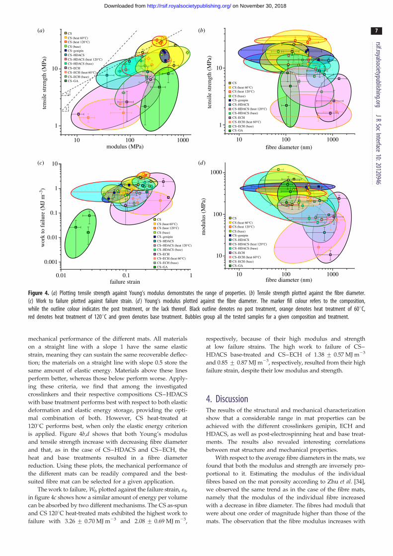
Figure 4. (a) Plotting tensile strength against Young’s modulus demonstrates the range of properties. (b) Tensile strength plotted against the fibre diameter.(c) Work to failure plotted against failure strain. (d ) Young’s modulus plotted against the fibre diameter. The marker fill colour refers to the composition,while the outline colour indicates the post treatment, or the lack thereof. Black outline denotes no post treatment, orange denotes heat treatment of 608C,red denotes heat treatment of 1208C and green denotes base treatment. Bubbles group all the tested samples for a given composition and treatment.
rsif.royalsocietypublishing.orgJR
SocInterface10:20120946
7
on November 30, 2018http://rsif.royalsocietypublishing.org/Downloaded from
mechanical performance of the different mats. All materials
on a straight line with a slope 1 have the same elastic
strain, meaning they can sustain the same recoverable deflec-
tion; the materials on a straight line with slope 0.5 store the
same amount of elastic energy. Materials above these lines
perform better, whereas those below perform worse. Apply-
ing these criteria, we find that among the investigated
crosslinkers and their respective compositions CS–HDACS
with base treatment performs best with respect to both elastic
deformation and elastic energy storage, providing the opti-
mal combination of both. However, CS heat-treated at
1208C performs best, when only the elastic energy criterion
is applied. Figure 4b,d shows that both Young’s modulus
and tensile strength increase with decreasing fibre diameter
and that, as in the case of CS–HDACS and CS–ECH, the
heat and base treatments resulted in a fibre diameter
reduction. Using these plots, the mechanical performance of
the different mats can be readily compared and the best-
suited fibre mat can be selected for a given application.
The work to failure, Wf, plotted against the failure strain, 1f,
in figure 4c shows how a similar amount of energy per volume
can be absorbed by two different mechanisms. The CS as-spun
and CS 1208C heat-treated mats exhibited the highest work to
failure with 3.26 + 0.70 MJ m23 and 2.08 + 0.69 MJ m23,
respectively, because of their high modulus and strength
at low failure strains. The high work to failure of CS–
HDACS base-treated and CS–ECH of 1.38 + 0.57 MJ m23
and 0.85 + 0.87 MJ m23, respectively, resulted from their high
failure strain, despite their low modulus and strength.
4. DiscussionThe results of the structural and mechanical characterization
show that a considerable range in mat properties can be
achieved with the different crosslinkers genipin, ECH and
HDACS, as well as post-electrospinning heat and base treat-
ments. The results also revealed interesting correlations
between mat structure and mechanical properties.
With respect to the average fibre diameters in the mats, we
found that both the modulus and strength are inversely pro-
portional to it. Estimating the modulus of the individual
fibres based on the mat porosity according to Zhu et al. [34],
we observed the same trend as in the case of the fibre mats,
namely that the modulus of the individual fibre increased
with a decrease in fibre diameter. The fibres had moduli that
were about one order of magnitude higher than those of the
mats. The observation that the fibre modulus increases with
1000
100
0.1 1 10
fibre–fibre contacts per unit volume (1 µm–3)
mat
mod
ulus
(M
Pa)
100 1000
CSCS (heat 60°C)CS (heat 120°C)CS (base)CS–genipinCS–HDACSCS–HDACS (heat 120°C)CS–HDACS (base)CS–ECHCS–ECH (heat 60°C)CS–ECH (base)CS–GA
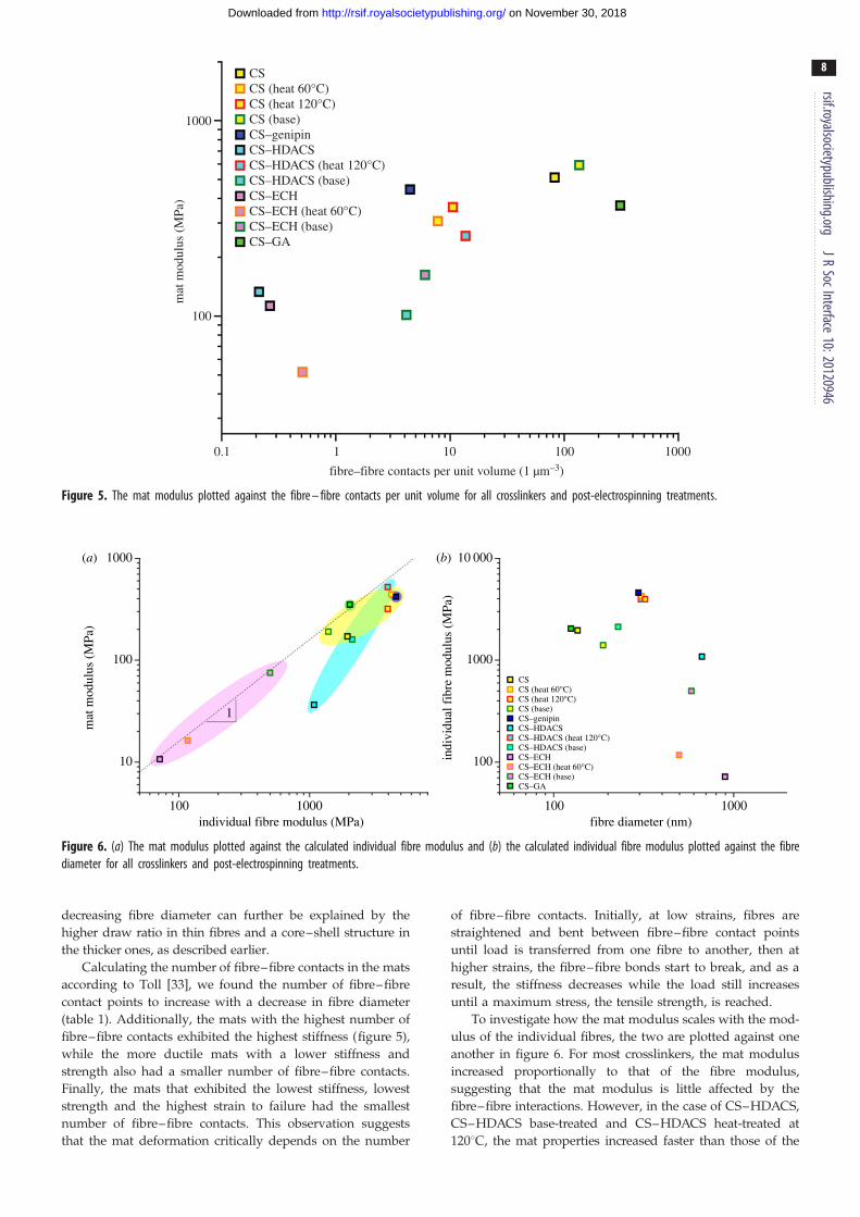
Figure 5. The mat modulus plotted against the fibre – fibre contacts per unit volume for all crosslinkers and post-electrospinning treatments.
1000(a) (b)
100
mat
mod
ulus
(M
Pa)
10 000
1000
100indi
vidu
al f
ibre
mod
ulus
(M
Pa)
10
1
100 1000individual fibre modulus (MPa)
100 1000fibre diameter (nm)
CSCS (heat 60°C)CS (heat 120°C)CS (base)CS–genipinCS–HDACSCS–HDACS (heat 120°C)CS–HDACS (base)CS–ECHCS–ECH (heat 60°C)CS–ECH (base)CS–GA
Figure 6. (a) The mat modulus plotted against the calculated individual fibre modulus and (b) the calculated individual fibre modulus plotted against the fibrediameter for all crosslinkers and post-electrospinning treatments.
rsif.royalsocietypublishing.orgJR
SocInterface10:20120946
8
on November 30, 2018http://rsif.royalsocietypublishing.org/Downloaded from
decreasing fibre diameter can further be explained by the
higher draw ratio in thin fibres and a core–shell structure in
the thicker ones, as described earlier.
Calculating the number of fibre–fibre contacts in the mats
according to Toll [33], we found the number of fibre–fibre
contact points to increase with a decrease in fibre diameter
(table 1). Additionally, the mats with the highest number of
fibre–fibre contacts exhibited the highest stiffness (figure 5),
while the more ductile mats with a lower stiffness and
strength also had a smaller number of fibre–fibre contacts.
Finally, the mats that exhibited the lowest stiffness, lowest
strength and the highest strain to failure had the smallest
number of fibre–fibre contacts. This observation suggests
that the mat deformation critically depends on the number
of fibre–fibre contacts. Initially, at low strains, fibres are
straightened and bent between fibre–fibre contact points
until load is transferred from one fibre to another, then at
higher strains, the fibre–fibre bonds start to break, and as a
result, the stiffness decreases while the load still increases
until a maximum stress, the tensile strength, is reached.
To investigate how the mat modulus scales with the mod-
ulus of the individual fibres, the two are plotted against one
another in figure 6. For most crosslinkers, the mat modulus
increased proportionally to that of the fibre modulus,
suggesting that the mat modulus is little affected by the
fibre–fibre interactions. However, in the case of CS–HDACS,
CS–HDACS base-treated and CS–HDACS heat-treated at
1208C, the mat properties increased faster than those of the

rsif.royalsocietypublishing.orgJR
SocInterface10:
9
on November 30, 2018http://rsif.royalsocietypublishing.org/Downloaded from
individual fibres, indicating that not only the fibre itself, but
also the fibre–fibre interactions are affected by the HDACS
and treatment.
Overall, the structure and the properties were affected by
the type of crosslinker, which crosslink by different mechan-
isms, as shown in part I of this study [20]. Additionally, while
some required the additional post-electrospinning treatments,
others did not. ECH, which resulted in the lowest values of
stiffness and strength, crosslinks with CS through the
amines or through the hydroxyl functional groups, depend-
ing on the reaction temperature [36]. HDACS, which
resulted in intermediate property values, crosslinks CS
through the formation of urea linkages under both heat and
base treatments. Genipin resulted in properties similar to
those of the as-spun CS mats, indicating that it is not cross-
linking the CS under these highly acidic conditions (TFA),
but rather modifying it by forming intermediates.
20120946
5. ConclusionThe picture that emerges from the results of the combinedstructural and mechanical characterization of this study is
that the properties of electrospun mats can be controlled
over a large range through both the choice of crosslinker
and post-electrospinning treatment. The different crosslinkers
and treatments strongly affect the fibre diameter and through
it the mat porosity and number of fibre–fibre contact points.
CS electrospun neat and with carefully chosen concentrations
of the crosslinkers genipin, ECH, HDACS and GA as well as
with or without heat and base treatments, resulted in a
library of fibre mats with a large range in properties. They
had Young’s moduli of 52–592 MPa, tensile strengths of 2–
30 MPa, failure strains of 2–31%, and toughness (work to fail-
ure) values of 0.041–3.26 MJ m23. Without post treatment, all
crosslinkers, except genipin lead to a decrease in both
Young’s modulus and tensile strength. Genipin under the
same conditions, resulted in a modulus and a tensile strength
similar to that of as-spun CS. For mats with post treatment,
both heat (at 608C and 1208C) and base, Young’s modulus
and tensile strength increased in comparison with the
untreated samples of the same composition.
What makes the electrospun CS fibre mats of this study
highly attractive is their versatility. Through the careful
choice of crosslinker, thermal and base treatments, structures
with different fibre diameters, porosities, chemical stabilities
and mechanical properties can be custom-designed, enabling
the most appropriate to be selected for a given application.
The authors wish to thank Dr Christopher Pastore of Philadelphia Uni-versity for his guidance and permission to use their climate controlledInstron. The authors also thank Gerard R. Klinzing and GregoryMuradyan for experimental assistance. They acknowledge the use ofthe Centralized Research Facilities in the College of Engineering atDrexel University and are grateful for funding through NSF-DMRgrant no. 0907572, NSF-CMMI grant no. 0804543, the GAANN Fellow-ship no. P200A070496 (A.E.D.), the NSF-IGERT Fellowship no.0654313 (A.E.D.), the Philadelphia Society of Women EngineersAward (A.E.D.), the Institute of Food Technology (PA section)(M.A.K.), the Drexel University Freshman Design Engineering Fellow-ship (M.A.K.), and the Ben Franklin Nanotechnology Institute, whichmade this research possible. U.G.K.W. wishes to express her gratitudeto Anne L. Stevens for the generous support of her research and groupwhile at Drexel University.
References
1. Schiffman JD, Schauer CL. 2008 A review:electrospinning of biopolymer nanofibers and theirapplications. Polym. Rev. 48, 317 – 352. (doi:10.1080/15583720802022182)
2. Jameela SR, Jayakrishnan A. 1995 Glutaraldehydecross-linked chitosan microspheres as a long actingbiodegradable drug delivery vehicle: studies on thein vitro release of mitoxantrone and in vivodegradation of microspheres in rat muscle.Biomaterials 16, 769 – 775. (doi:10.1016/0142-9612(95)99639-4)
3. Sangsanoh P, Supaphol P. 2006 Stabilityimprovement of electrospun chitosan nanofibrousmembranes in neutral or weak basic aqueoussolutions. Biomacromolecules 7, 2710 – 2714.(doi:10.1021/bm060286l)
4. Schiffman JD, Schauer CL. 2007 Cross-linkingchitosan nanofibers. Biomacromolecules 8,594 – 601. (doi:10.1021/bm060804s)
5. De Vrieze S, Westbroek P, Van Camp T, VanLangenhove L. 2007 Electrospinning of chitosannanofibrous structures: feasibility study. J. Mater. Sci.42, 8029 – 8034. (doi:10.1007/s10853-006-1485-6)
6. Schiffman JD, Schauer CL. 2007 One-stepelectrospinning of cross-linked chitosan fibers.Biomacromolecules 8, 2665 – 2667. (doi:10.1021/bm7006983)
7. Cai Z-X, Mo X-M, Zhang K-H, Fan L-P, Yin A-L, HeC-L, Wang H-S. 2010 Fabrication of chitosan/silkfibroin composite nanofibers for wound-dressingapplications. Int. J. Mol. Sci. 11, 3529 – 3539.(doi:10.3390/ijms11093529)
8. Vondran JL, Sun W, Schauer CL. 2008 Crosslinked,electrospun chitosan – poly(ethylene oxide)nanofiber mats. J. Appl. Polym. Sci. 109, 968 – 975.(doi:10.1002/app.28107)
9. Desai K, Kit K, Li J, Zivanovic S. 2008 Morphologicaland surface properties of electrospun chitosannanofibers. Biomacromolecules 9, 1000 – 1006.(doi:10.1021/bm701017z)
10. Ohkawa K, Cha D, Kim H, Nishida A, Yamamoto H. 2004Electrospinning of chitosan. Macromol. Rapid Commun.25, 1600 – 1605. (doi:10.1002/marc.200400253)
11. Chiou MS, Li HY. 2003 Adsorption behavior ofreactive dye in aqueous solution on chemicalcross-linked chitosan beads. Chemosphere 50,1095 – 1105. (doi:10.1016/S0045-6535(02)00636-7)
12. Touyama R, Inoue K, Takeda Y, Yatsuzuka M,Ikumoto T, Moritome N, Shingu Y, Inouye H. 1994Studies on the blue pigments produced fromgenipin and methylamine. II. On the formationmechanisms of brownish-red intermediates leadingto the blue pigment formation. Chem. Pharm. Bull.42, 1571 – 1578. (doi:10.1248/cpb.42.1571)
13. Touyama R, Takeda Y, Inoue K, Kawamura I,Yatsuzuka M, Ikumoto T, Shingu Y, Inouye H. 1994Studies on the blue pigments produced fromgenipin and methylamine. I. Structures of thebrownish-red pigments, intermediates leading tothe blue pigments. Chem. Pharm. Bull. 42,668 – 673. (doi:10.1248/cpb.42.668)
14. Mi F-L, Tan Y-C, Liang H-C, Huang R-N, Sung H-W.2001 In vitro evaluation of a chitosan membrane cross-linked with genipin. J. Biomater. Sci. Polym. Ed. 12,835 – 850. (doi:10.1163/1568562017 53113051)
15. Mi F-L, Sung H-W, Shyu S-S. 2000 Synthesis andcharacterization of a novel chitosan-based networkprepared using naturally occurring crosslinker.J. Polym. Sci. A Polym. Chem. 38, 2804 – 2814.(doi:10.1002/1099-0518(20000801)38:15,2804::aid-pola210.3.0.co;2-y)
16. Welsh ER, Schauer CL, Qadri SB, Price RR. 2002Chitosan cross-linking with a water-soluble, blockeddiisocyanate. 1. Solid State. Biomacromolecules 3,1370 – 1374. (doi:10.1021/bm025625z)
17. Welsh ER, Schauer CL, Santos JP, Price RR. 2004In situ cross-linking of alternating polyelectrolytemultilayer films. Langmuir 20, 1807 – 1811. (doi:10.1021/la035798p)
18. Schauer CL, Chen M-S, Price RR, Schoen PE, LiglerFS. 2004 Colored thin films for specific metal ion

rsif.royalsocietypublishing.orgJR
SocInterface10:20120946
10
on November 30, 2018http://rsif.royalsocietypublishing.org/Downloaded from
detection. Environ. Sci. Technol. 38, 4409 – 4413.(doi:10.1021/es035047+)
19. Wan Ngah WS, Endud CS, Mayanar R. 2002 Removalof copper(II) ions from aqueous solution ontochitosan and cross-linked chitosan beads. ReactiveFunct. Polym. 50, 181 – 190. (doi:10.1016/S1381-5148(01)00113-4)
20. Austero MS, Donius AE, Wegst UGK, Schauer CL.2012 New crosslinkers for electrospun chitosan fibremats. I. Chemical analysis. J. R. Soc. Interface 9,2551 – 2562. (doi:10.1098/rsif.2012.0241)
21. Muzzarelli RAA. 2009 Genipin-crosslinked chitosanhydrogels as biomedical and pharmaceutical aids.Carbohydr. Polym. 77, 1 – 9. (doi:10.1016/j.carbpol.2009.01.016)
22. Lee S-H, Park S-M, Kim Y. 2007 Effect of theconcentration of sodium acetate (SA) on crosslinkingof chitosan fiber by epichlorohydrin (ECH) in a wetspinning system. Carbohydr. Polym. 70, 53 – 60.(doi:10.1016/j.carbpol.2007.03.002)
23. Lee S-H, Park S-Y, Choi J-H. 2004 Fiber formationand physical properties of chitosan fiber crosslinkedby epichlorohydrin in a wet spinning system: theeffect of the concentration of the crosslinkingagent epichlorohydrin. J. Appl. Polym. Sci. 92,2054 – 2062. (doi:10.1002/app.20160)
24. Wei YC, Hudson SM, Mayer JM, Kaplan DL. 1992The crosslinking of chitosan fibers. J. Polym. Sci. APolym. Chem. 30, 2187 – 2193. (doi:10.1002/pola.1992.080301013)
25. Chen F, Porter D, Vollrath F. 2010 Silkworm cocoonsinspire models for random fiber and particulatecomposites. Phys. Rev. E 82, 041911. (doi:10.1103/PhysRevE.82.041911)
26. I’Anson SJ, Sampson WW. 2007 Competing Weibulland stress-transfer influences on the specifictensile strength of a bonded fibrous network.Compos. Sci. Technol. 67, 1650 – 1658. (doi:10.1016/j.compscitech.2006.07.002)
27. Baji A, Mai Y-W, Wong S-C, Abtahi M, Chen P. 2010Electrospinning of polymer nanofibers: effects onoriented morphology, structures and tensileproperties. Compos. Sci. Technol. 70, 703 – 718.(doi:10.1016/j.compscitech.2010.01.010)
28. Batchelor W, He J, Sampson W. 2006 Inter-fibrecontacts in random fibrous materials: experimentalverification of theoretical dependence on porosityand fibre width. J. Mater. Sci. 41, 8377 – 8381.(doi:10.1007/s10853-006-0889-7)
29. Elias TC. 1967 Investigation of the compressionresponse of ideal unbounded fibrous structures.TAPPI J. 50, 125.
30. Eichhorn SJ, Sampson WW. 2009 Relationshipsbetween specific surface area and pore sizein electrospun polymer fibre networks. J. R.Soc. Interface 7, 641 – 649. (doi:10.1098/rsif.2009.0374)
31. Berhan L, Yi YB, Sastry AM. 2004 Effect of nanoropewaviness on the effective moduli of nanotubesheets. J. Appl. Phys. 95, 5027 – 5034. (doi:10.1063/1.1687989)
32. Eichhorn SJ, Sampson WW. 2005 Statisticalgeometry of pores and statistics of porousnanofibrous assemblies. J. R. Soc. Interface 2,309 – 318. (doi:10.1098/rsif.2005.0039)
33. Toll S. 1998 Packing mechanics of fiberreinforcements. Polym. Eng. Sci. Polym. Eng. Sci. 38,1337 – 1350. (doi:10.1002/pen.10304)
34. Zhu HX, Mills NJ, Knott JF. 1997 Analysis of thehigh strain compression of open-cell foams. J. Mech.Phys. Solids 45, 1875 – 1904. (doi:10.1016/S0022-5096(97)00027-6)
35. Gibson LJ, Ashby MF. 1982 The mechanics of three-dimensional cellular materials. Proc. R. Soc. Lond. A382, 43 – 59. (doi:10.1098/rspa.1982.0088)
36. Zheng H, Du YM, Yu JH, Xiao L. 2000 The propertiesand preparation of crosslinked chitosan films.Chem. J. Chin. Univ. Chin. 21, 809 – 812.