New cooling approach and tool life improvement in ...ered/ME482/Paper_Topics/McFarlandPaper.pdf ·...
16
International Journal of Machine Tools & Manufacture 41 (2001) 2245–2260 New cooling approach and tool life improvement in cryogenic machining of titanium alloy Ti-6Al-4V Shane Y. Hong * , Irel Markus, Woo-cheol Jeong Department of Mechanical Engineering, Columbia University, New York, NY 10027, USA Received 21 October 1999; received in revised form 17 March 2001; accepted 27 March 2001 Abstract Titanium alloy Ti-6Al-4V, a difficult-to-machine material because of its extremely short tool life, has been a major subject for cryogenic machining research. However, the approaches reported in past publi- cations are inherently flawed. This study reviews how the temperature affects Ti-6Al-4V properties, and compares different cryogenic cooling strategies. Based on these findings, a new economical cryogenic cooling approach is proposed. Using a minimum amount of liquid nitrogen (LN2), this innovation features a specially designed micro-nozzle. Formed between the chip breaker and the tool rake face, the nozzle lifts the chip and injects focused LN2 into the chip–tool interface at the point of highest temperature. As the nitrogen evaporates, a nitrogen cushion formed by evaporating nitrogen lowers the coefficient of friction between the chip and the tool. An auxiliary mini-nozzle that sprays LN2 onto the flank at the cutting edge further reduces the cutting temperature. The study finds that the combination of these two micro-nozzles provides the most effective cooling while using the lowest LN2 flow rate. Improving the position of the nozzle/chip breaker further enhances the performance. Our cryogenic machining tests show that tool life increases up to five times the state-of the-art emulsion cooling, outperforming other machining approaches. 2001 Elsevier Science Ltd. All rights reserved. Keywords: Titanium machining; Cryogenic machining; Tool wear; Tool life; Nozzle design 1. Introduction Titanium is a relatively lightweight metal that provides excellent corrosion resistance, a high strength-to-weight ratio, and good high temperature properties. Pure titanium is allotropic, with an HCP crystal structure (α phase) at low temperatures and a BCC structure (β phase) above * Corresponding author. Tel.: +1-212-854-2957; fax: +1-212-954-3304. E-mail address: [email protected] (S.Y. Hong). 0890-6955/01/$ - see front matter 2001 Elsevier Science Ltd. All rights reserved. PII:S0890-6955(01)00041-4
Transcript of New cooling approach and tool life improvement in ...ered/ME482/Paper_Topics/McFarlandPaper.pdf ·...

International Journal of Machine Tools & Manufacture 41 (2001) 2245–2260
New cooling approach and tool life improvement incryogenic machining of titanium alloy Ti-6Al-4V
Shane Y. Hong*, Irel Markus, Woo-cheol JeongDepartment of Mechanical Engineering, Columbia University, New York, NY 10027, USA
Received 21 October 1999; received in revised form 17 March 2001; accepted 27 March 2001
Abstract
Titanium alloy Ti-6Al-4V, a difficult-to-machine material because of its extremely short tool life, hasbeen a major subject for cryogenic machining research. However, the approaches reported in past publi-cations are inherently flawed. This study reviews how the temperature affects Ti-6Al-4V properties, andcompares different cryogenic cooling strategies. Based on these findings, a new economical cryogeniccooling approach is proposed. Using a minimum amount of liquid nitrogen (LN2), this innovation featuresa specially designed micro-nozzle. Formed between the chip breaker and the tool rake face, the nozzlelifts the chip and injects focused LN2 into the chip–tool interface at the point of highest temperature. Asthe nitrogen evaporates, a nitrogen cushion formed by evaporating nitrogen lowers the coefficient of frictionbetween the chip and the tool. An auxiliary mini-nozzle that sprays LN2 onto the flank at the cutting edgefurther reduces the cutting temperature. The study finds that the combination of these two micro-nozzlesprovides the most effective cooling while using the lowest LN2 flow rate. Improving the position of thenozzle/chip breaker further enhances the performance. Our cryogenic machining tests show that tool lifeincreases up to five times the state-of the-art emulsion cooling, outperforming other machining approaches. 2001 Elsevier Science Ltd. All rights reserved.
Keywords: Titanium machining; Cryogenic machining; Tool wear; Tool life; Nozzle design
1. Introduction
Titanium is a relatively lightweight metal that provides excellent corrosion resistance, a highstrength-to-weight ratio, and good high temperature properties. Pure titanium is allotropic, withan HCP crystal structure (α phase) at low temperatures and a BCC structure (β phase) above
* Corresponding author. Tel.:+1-212-854-2957; fax:+1-212-954-3304.E-mail address: [email protected] (S.Y. Hong).
0890-6955/01/$ - see front matter 2001 Elsevier Science Ltd. All rights reserved.PII: S0890-6955(01)00041-4

2246 S.Y. Hong et al. / International Journal of Machine Tools & Manufacture 41 (2001) 2245–2260
882°C. Alloying elements have the effects of strengthening solid solutions and changing the allo-tropic transformation temperature. Ti-6Al-4V is the representative system of α+β alloys, and isthe most commonly used alloy in the aerospace industry. It accounts for about 50% of totaltitanium production.
Titanium and its alloys are classified as difficult-to-machine materials. The main problems inmachining them are the high cutting temperatures and the rapid tool wear. Most tool materialswear rapidly even at moderate cutting speeds. To minimize tool wear, current machining practicelimits the cutting speed to less than 1 m/s. The machining characteristics for titanium and itsalloys are summarized below [1–4].
1. Titanium and its alloys are poor thermal conductors. As a result, the heat generated whenmachining titanium cannot dissipate quickly; rather, most of the heat is concentrated on thecutting edge and tool face.
2. Titanium has a strong alloying tendency or chemical reactivity with the cutting tool materialat tool operation temperatures. This causes galling, welding, and smearing, along with rapidwear or cutting tool failure.
3. During machining, titanium alloys exhibit thermal plastic instability which leads to uniquecharacteristics of chip formation. The shear strains in the chip are not uniform; rather, they arelocalized in a narrow band that forms serrated chips.
4. The contact length between the chip and the tool is extremely short (less than one-third thecontact length of steel with the same feedrate and depth of cut). This implies that the highcutting temperature and the high stress are simultaneously concentrated near the cutting edge(within 0.5 mm).
5. Serrated chips create fluctuations in the cutting force; this situation is further promoted whenalpha–beta alloys are machined. The vibrational force, together with the high temperature,exerts a micro-fatigue loading on the cutting tool, which is believed to be partially responsiblefor severe flank wear.
Titanium and its alloys represent the most challenging materials in machining. With advancesin cutting tool materials, many difficult-to-machine materials can now be machined at highermetal removal rates. None of these tool materials, however, seems to be effective in machiningtitanium because of their chemical affinities with titanium. New development in tool coating alsodoes not help titanium machining. Al2O3 coating has a lower thermal conductivity than the tung-sten carbide insert, which prevents heat dissipation from extremely concentrated high stress andhigh temperature at the cutting point. Titanium carbide and titanium nitride coatings are not suit-able for machining titanium alloys because of their chemical affinities. Thus, cryogenic machining,which is able to both lower the cutting temperature and enhance chemical stability of the work-piece and the tool, is expected to greatly increase productivity level in the machining of titaniumand its alloys.
Most cryogenic machining studies on titanium and its alloys [5–14] have documented improvedmachinability when freezing the workpiece or cooling the tool using a cryogenic coolant. How-ever, as discussed in the next section, inherent weaknesses exist in these approaches. Recentimprovements in state-of-the-art conventional machining further negate the advantages reportedin these studies.

2247S.Y. Hong et al. / International Journal of Machine Tools & Manufacture 41 (2001) 2245–2260
Prompted by the environmental concern about conventional cutting fluid, cryogenic machininghas received increased attention with the aim of finding an economical and ecological alternativefor metal cutting industry. Under the cooperation of 12 US companies representing the machine,tool, cryogen, automobile, and aerospace industries, this study was part of the research programto develop an economical cryogenic machining approach for high speed cutting of difficult-to-machine materials. The goal was to find the most effective cryogenic cooling approach that willyield the longest tool life while using minimum amounts of liquid nitrogen (LN2). After initialtryout of machining Ti-6Al-4V, the cryogenic machining approach by flooding LN2 yielded verygood results compared to dry cutting; unfortunately the tool life was just close to the state-of-the-art conventional emulsion cooling as described later in this paper. This result indicated that tomake cryogenic machining a viable process would require improvements through comprehensivetheoretical study and practical system development. Since then, the following studies have beenconducted: (1) cryogenic temperature effects on the material properties of both workpiece [15]and tool material [16]; (2) cutting temperatures and different cooling approaches [17]; (3) frictionand cutting forces [18]; (4) design improvements for a new cryogenic nozzle and delivery line.Applying the results of these studies, an innovative approach was adopted and it emerged as themost effective cryogenic machining system. This paper discloses the design of our innovativecryogenic machining system, and reports the effectiveness of this approach for improving tool life.
2. New approach for cryogenic machining
2.1. Temperature effect on material properties and cooling considerations
Annealed Ti-6Al-4V has a microstructure consists of a coarse, plate-like alpha phase and agrain boundary beta phase. Its strength and the elongation with respect to temperature change[19–21] are presented in Fig. 1. Our own findings on titanium and its variation in hardness withtemperature change are shown in Fig. 2. As shown, the strength of Ti-6Al-4V increases rapidlyas the temperature is decreased. For instance, when titanium changes from room temperature toliquid nitrogen temperature, tensile strength changes from 1000 to 1700 MPa. This means thatthe cutting force will increase, consuming more power and generating more heat. With regard toimpact strength, tensile elongation and reduction in area, the research literature is not consistent.However, most data showed that even at liquid nitrogen temperature Ti-6Al-4V sustains its tough-ness and ductility, without the apparent ductility to brittleness transition common for carbon steels.Cooling the material does not improve the chip as in the successful case of cutting low carbonsteel reported in [22]. On the other hand, the hardness of Ti-6Al-4V increases quickly as thetemperature decreases. Thus, the decreased temperature of the workpiece tends to increase theabrasion of the chip to the cutting tool. Clearly, cryogenically cooling the workpiece is not desir-able.
Cutting temperatures for Ti-6Al-4V can easily reach 1000°C, which will soften the cutting toolmaterial and accelerate tool failure. When LN2 is used to cool the tool cutting edge surfaces, theincreased hardness of the tool can improve the tool wear and expand the tool life. Our toolmaterial study [16] showed that the strength and harness of the carbide tool material increased

2248 S.Y. Hong et al. / International Journal of Machine Tools & Manufacture 41 (2001) 2245–2260
Fig. 1. The strength and elongation of Ti-6Al-4V versus temperature.
Fig. 2. The hardness of Ti-6Al-4V versus temperature.
under cryogenic temperatures, but the impact strength was not weakened. As result of materialstudies, it is recommended that the cutting tools, but not the workpiece materials, be cooled.
In the past, common cryogenic machining cooling approaches have included: (1) pre-coolingthe workpiece [11], (2) indirect cooling [12,23], (3) general flooding [24], and (4) an enclosedbath [9,10]. Each of the approaches as reported in the cited research has flaws. Pre-cooling the

2249S.Y. Hong et al. / International Journal of Machine Tools & Manufacture 41 (2001) 2245–2260
workpiece and enclosing the workpiece in a cryogenic bath are not practical in the productionline and negatively increase the cutting force and the abrasion to the tool. Indirect cooling bythermal conduction through the tool body is highly dependent on the thermal conductivity of thetool material and the distance from the LN2 source to the highest temperature point at the cuttingedge. In general, indirect cooling is not effective. General flooding, like conventional emulsioncooling, is favored by many; however, this approach wastes a large amount of liquid nitrogen,often cooling unwanted areas causing a negative effect such as pre-cooling the workpiece. Cur-rently, no cryogenic cooling approach exists that is economical and practical enough to replaceconventional machining.
2.2. New economical cryogenic cooling approach
This paper introduces an innovative cryogenic cooling approach composed of the following con-cepts:
1. To minimize waste, cryogenic fluid is applied directly to, and only to, the tip of the cuttingtool, where the material is being cut and heat is being generated.
2. The flowrate of the cryogenic fluid is proportional to the heat generated in the cutting process,preventing the workpiece from becoming distorted due to extremes of heating or cooling.
3. The micro-nozzle is located between the tool face and chip breaker as a commercial new cuttingtool assembly, a design that is economical and convenient for users.
Fig. 3 exemplifies the cryogenic machining cooling concepts using a flat cutting insert with anobstruction chip breaker. Liquid nitrogen is released through a nozzle between the chip breakerand the rake face of the tool insert. The chip breaker helps to lift the chip to allow liquid nitrogento reach and cool the highest temperature spot—the tool–chip interface. Unlike general flooding,the chip does not block the flow of liquid nitrogen. The liquid nitrogen absorbs the heat, evaporatesquickly, and forms a fluid/gas cushion between the chip and tool face that functions as a lubricant.Consequently, the coefficient of friction is reduced, as well as the secondary deformation in thechip, as documented in our study [18]. Both the lubrication effect and cooling the hottest spotreduce the tool temperature, in turn effectively reducing both crater and flank wears. An auxiliarycryogenic nozzle may be added to cool the flank face near the cutting point for further reductionof flank wear.
2.3. Design implementation
Fig. 4 illustrates the nozzle for a flat cutting insert. The nozzle is formed by placing a modifiedchip breaker on the tool insert. Channeled grooves are etched on the bottom of a standard carbidechip breaker. Liquid nitrogen flows from a vacuum-jacketed delivery line through a hole on thechip breaker to these channels and is released onto the cutting edge. The channels, formed byelectrical discharge machining (EDM) for this study, can be economically mass-produced bymolding the carbide green compact in the powder metallurgy process. The low profiled nozzleprevents the chip blocking the LN2 flow, yet the carbide construction is strong enough to resistwear by the chip.

2250 S.Y. Hong et al. / International Journal of Machine Tools & Manufacture 41 (2001) 2245–2260
Fig. 3. A schematic of the economical cryogenic machining approach.
To accommodate severe flank wear in machining titanium, the liquid nitrogen supply can bebranched to an auxiliary nozzle that sprays the cutting edge on the flank surface. In this case, thesecondary nozzle is integrated with the LN2 supply block. Fig. 4(a) shows when both nozzlesare used. To turn off the secondary nozzle, the block is slid back as shown in Fig. 4(b). Fig. 5shows a photograph of the nozzle assembly with LN2 flowing. Nozzle designs were developedfor differently formed tool inserts with a built-in chip breaker for machining steels [25]. Otherdesigns have the nozzle groove built on the tool insert rather than on the chip breaker.
3. Machining tests and tool life comparison
3.1. Experiment setup
To be meaningful, evaluation of cryogenic machining must be based on realistic conditions.The machine, cutting tool, and cutting conditions must be comparable to industrial state-of-the-art standards. In this study, the machining tests were performed according to international standardISO 3685:1993 [26]. Cincinnati-Milacron Cinturn 1408C, a 30 HP slant bed computer numericalcontrolled (CNC) turning center, was used for machining tests. The CNC controller is capable ofmaintaining a constant surface speed at different work diameters. A commercial cutting tool,

2251S.Y. Hong et al. / International Journal of Machine Tools & Manufacture 41 (2001) 2245–2260
Fig. 4. The design implementation of the cryogenic nozzle. (a) When both primary nozzle and auxiliary nozzle areused to inject liquid nitrogen; (b) only the primary nozzle is used.
Kennametal insert CNMA432-K68, a typical carbide grade for cutting titanium, was mounted onthe CNC’s turret. This insert is a tough WC/Co unalloyed grade, equivalent to ANSI C2-C3, orISO K05-K15, M10-M20.
When machining titanium, tool life is most affected by cutting speed, but it is also sensitiveto the feed and depth of cut. A fixed depth of cut 1.27 mm (0.050 in) and feed 0.254 mm (0.010in) was selected based on the Machining Data Handbook [27] and recommendations from ourindustrial sponsors. The cutting speed commonly used in industry is only 1 m/s (200 ft/min).Some companies have tried 1.5 m/s. With the potential for higher cutting speeds in cryogenicmachining, the speeds tested in this study included 1, 1.5, 2.0, and 2.5 m/s (200, 300, 400, and500 ft/min).
The following tool life criteria were used according to the ISO standard [26]:
1. Average flank wear: 0.3 mm, or

2252 S.Y. Hong et al. / International Journal of Machine Tools & Manufacture 41 (2001) 2245–2260
Fig. 5. A photograph showing LN2 flowing out of the nozzle.
2. Maximum flank wear: 0.6 mm, or3. Depth of crater wear KT: 0.06 mm+0.3 x feed.
Since a comparatively low crater wear was observed consistently for all cuttings of Ti6-4, thetool life was predominantly based on average flank wear of 0.3 mm or maximum flank wear of0.6 mm, whichever criterion it reached first. During the test, tool wear was measured by anoptical microscope.
3.2. Conventional emulsion machining tests as baselines for comparison
To establish a base for comparing tool life for cryogenic machining, conventional machiningtests were conducted under supervision of the machining specialists of our tool and aerospaceindustrial research partners. The cutting tool and workpiece were flooded with high performancecommercial emulsion coolant. The emulsion cutting fluid was obtained by mixing the concentratewith water at a ratio of 1:20. The coolant flowed at a rate of 4.9 liter/min (1.35 gal/min). Thetool life measured was 15 min 48 s for a cutting speed of 1.0 m/s, 4 min 56 s for 1.5 m/s, 3 minfor 2 m/s and 56 s for 2.5 m/s respectively. These conventional machining tool life data are longerthan reported in other cryogenic machining studies, and are believed to be the state-of-the-artaccording to machining specialists.

2253S.Y. Hong et al. / International Journal of Machine Tools & Manufacture 41 (2001) 2245–2260
3.3. Flooding method in cryogenic machining
The flooding method of applying LN2 in machining consumed large quantities of LN2 butyielded poor tool life results. In the early stages of our cryogenic machining study, the generalflooding of liquid nitrogen to the cutting tool as in conventional emulsion cooling was tested.LN2 was supplied through a vacuum-jacketed line to the cutting zone from a commercial cylinder,by its own pressure of 1.4–2.4 MPa. The volumetric flowrate was measured by a Hoffer miniatureturbine flowmeter, which had been calibrated by the weight reduction of the liquid nitrogen tankon an electronic scale. Machining tests were conducted under the same cutting parameters asconventional machining.
Without using the special nozzle described in this paper, the tool life was only 5 min 26 s at1.5 m/s when using one nozzle to flood LN2 to the general cutting area with the high flowrateof 0.019 kg/s (0.375 gal/min). This tool life is about the same as conventional emulsion cooling.Subsequently, one additional nozzle was added to cool the flank surface. The LN2 flowrate wasincreased to 0.056 kg/s (1.1 gal/min). When using two nozzles for general flooding, the tool lifeimproved to 8 min 45 s.
Fig. 6 shows the results of multiple tests using flooding methods for cutting speeds of 1.0, 1.5,2, and 2.5 m/s. The single nozzle-flooding mode has a shorter tool life than conventional machin-ing with the emulsion coolant at the normal cutting speed of 1 m/s, and they are about the samefor higher speeds. Even though using a two-nozzle flooding mode improves the tool life, it couldnot be economically justified due to the large volume of LN2 consumed. As described in theintroduction, a more effective cryogenic cooling approach was needed. As a result of fundamentalstudies on aspects of material, temperature, and lubrication effects, this study redirected its focusto the new economical cryogenic cooling method, which will be discussed below.
Fig. 6. Tool life comparison between flooding LN2 and emulsion cooling.

2254 S.Y. Hong et al. / International Journal of Machine Tools & Manufacture 41 (2001) 2245–2260
Fig. 7. Tool life comparison of different cooling approaches at 1.5 m/s (300 ft/min).
3.4. Machining test using the new economical cryogenic machining approach
The new economical cryogenic machining approach uses LN2 of low flowrate focused to thecutting point, which significantly improves the tool life. As described above, two nozzles coolthe tool rake and tool flank, respectively. The effectiveness of the rake nozzle (primary nozzle)and the flank nozzle (secondary nozzle) was evaluated by the standard machining test at 1.5 m/s.The tool wear rate for different cooling methods are compared in Fig. 7. The tool life was 547s for rake cooling by the primary nozzle (flowrate 0.49 kg/min), 238 s for flank cooling by onlythe secondary nozzle (0.43 kg/min), and 948 s for both rake and flank cooling by two nozzles(0.65 kg/min). For comparison, the tool life was 167 s for dry cutting and 290 s for emulsioncooling. As shown in Table 1, these test results agree with the temperature analysis using finite
Table 1Highest temperatures at the cutting tool insert measured by the imbedded thermal couple at the tool insert and obtainedby finite element (FE) analysis and their corresponding tool lives
Cooling approach Measured (°C) FE max (°C) LN2 flowrate Tool life (s)(kg/min)
Dry cutting 865 1072 N/A 167Emulsion cooling 524 488* N/A 290Cooling tool back by LN2 648 787 0.91 N/APre-cooling workpiece by 481 408** 0.91 N/ALN21 LN2 jet to flank 447 526 0.43 2381 LN2 jet to rake 335 437 0.49 5472 LN2 nozzles on 208 265 0.65 948
* Assume the workpiece is cooled to LN2 temperature.** Assume a perfect distribution of emulsion to the cutting edge.
2255S.Y. Hong et al. / International Journal of Machine Tools & Manufacture 41 (2001) 2245–2260
elements and thermal couple measurements detailed in the cooling approaches and cutting tem-peratures paper by the author [17].
Since flank wear is the main tool life criterion when machining Ti-6Al-4V, flank cooling mightbe a direct approach to reducing flank wear. However, directing one LN2 jet to the tool flankonly was less effective than conventional emulsion cooling (i.e. higher temperature and shortertool life). On the contrary, cooling the tool rake by the primary nozzle outperformed emulsioncooling, largely because LN2 was directed to the highest temperature on the rake. In addition,LN2 provided the lubrication between the chip and the tool rake as disclosed in another paperby the author on friction and cutting forces in cryogenic machining [18]. From this preliminarystudy, cooling both rake and flank provided sufficient cooling and lubrication and yielded the besttool life. Clearly, focused cooling with a small LN2 flowrate to the rake, or to both the rake andflank, are the preferred approaches for cryogenic machining.
3.5. Study of the effect of nozzle/chip breaker positioning on tool life
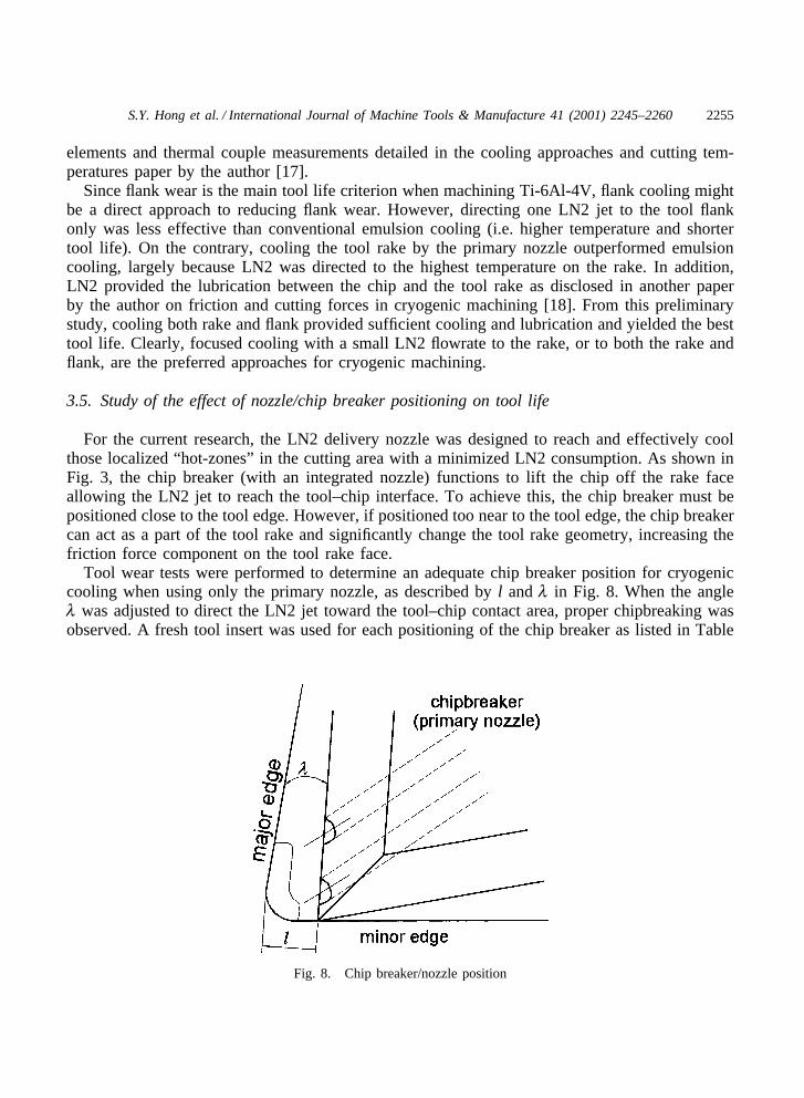
For the current research, the LN2 delivery nozzle was designed to reach and effectively coolthose localized “hot-zones” in the cutting area with a minimized LN2 consumption. As shown inFig. 3, the chip breaker (with an integrated nozzle) functions to lift the chip off the rake faceallowing the LN2 jet to reach the tool–chip interface. To achieve this, the chip breaker must bepositioned close to the tool edge. However, if positioned too near to the tool edge, the chip breakercan act as a part of the tool rake and significantly change the tool rake geometry, increasing thefriction force component on the tool rake face.
Tool wear tests were performed to determine an adequate chip breaker position for cryogeniccooling when using only the primary nozzle, as described by l and l in Fig. 8. When the anglel was adjusted to direct the LN2 jet toward the tool–chip contact area, proper chipbreaking wasobserved. A fresh tool insert was used for each positioning of the chip breaker as listed in Table
Fig. 8. Chip breaker/nozzle position

2256 S.Y. Hong et al. / International Journal of Machine Tools & Manufacture 41 (2001) 2245–2260
Table 2Positions of chip breaker
Position No. 1 2 3 4 5 6
l (mm) 1.75 1.50 1.25 1.25 1.25 1.00l (deg) 15 15 15 20 10 10
2. The average and maximum widths of the flank wear, VB and VBmax, as defined in the ISOstandard [26], were measured under a tool microscope. The tool wear tested at a speed of 1.5m/s is plotted in Fig. 9. Because the chip breaker at Positions No. 1 and No. 2 were too far fromthe cutting edge, it failed to lift up the flowing chip for the pressurized LN2 jet to reach the hotspot on the rake face. Therefore, both positions led to a high rate of flank wear. The high rateof flank wear for Position No. 6 may have been because the chip at this position (or closer) tendsto block the primary nozzle and change the effective tool rake angle.Positions No. 3, No. 4 and No. 5 each showed comparatively low rates of flank wear, with PositionNo. 3 producing the lowest rate. The effectiveness of the chip breaker position is again verifiedwith tool life tests conducted twice. The averaged tool lives for Positions No. 3, No. 4, and No.5 were 8.85, 7.80 and 7.35 min, respectively. Position No. 3 offered the best tool life. For cryo-genic cooling using the primary nozzle, Position No. 3 also tends to produce a lower coefficientof friction as detailed in a previous study [18].
3.6. Full-scale machining test and tool life comparison
Table 3 lists the all the tool lives determined experimentally for different cutting speeds basedon the ISO standard. The cutting tests were all performed with and without using chip breakerPosition No. 3. The tool life data obtained for emulsion-cooled cutting are included here as areference. For the cryogenic cooling, especially with “ two nozzles on” , an adequate tool life can
Fig. 9. Tool wear VBmax for different chip breaker positions at 1.5 m/s.

2257S.Y. Hong et al. / International Journal of Machine Tools & Manufacture 41 (2001) 2245–2260
Table 3Tool life testing result for machining Ti-6Al-4V
Cutting speed Coolant flowrate
1.0 m/s (200 1.5 m/s (300 2.0 m/s (400 2.5 m/s (500sfm) sfm) sfm) sfm)
Conventional emulsion 17�30� 4�50� 2�38� 56� 5.1 kg/min (1.35gal/min)
LN2 cooling using only 19�42� 6�15� 3�05� 1�27� 0.62 kg/minthe primary nozzle at (0.205 gal/min)not-optimized positionLN2 cooling using both 23�15� 12�03� 6�15� 4�02� 0.84 kg/minnozzles, the chip (0.277 gal/min)breaker location is notoptimizedLN2 cooling with only 9�07� 0.48 kg/minprimary nozzle with (0.160 gal/min)optimized chip breakerpositionLN2 cooling with 27�33� 15�48� 7�17� 4�56� 0.65 kg/minoptimized chip breaker (0.215 gal/min)position (2 nozzles)
be obtained even at a cutting speed of 2.5 m/min, at which even the emulsion cooling can onlylead to an unacceptable tool life (less than 1 min).
For industries that refer to tool life in terms of total volume of workpiece material removedbefore replacing the tool, the tool life data were converted into volume removal versus speed, asplotted as in Fig. 10. Cryogenic machining dramatically increased the tool life. These increaseswere more significant at higher cutting speeds. For example, the tool life in cryogenic machiningwas up to five times longer than in conventional machining at a speed of 2.5 m/s (500 ft/min).Longer tool life in cryogenic machining allows companies to cut materials at higher speeds.
4. Discussion
The Taylor tool life equation for a fixed feed and depth of cut is generally expressed as:
VT n�C
where T is the tool life in minutes, and V is the cutting speed in surface feet per minute. Theindex n depends mainly on the tool material, and C is the cutting speed for a 1-minute tool life,which is a function of the workpiece material strength and tool materials. To fit the test resultsinto the Taylor tool life equation, the tool life was plotted against the cutting speed on a log–logscale (see Fig. 11). We obtained the following constants of the equation:
For emulsion coolant: n=0.3214, C=507.

2258 S.Y. Hong et al. / International Journal of Machine Tools & Manufacture 41 (2001) 2245–2260
Fig. 10. Expanded tool life testing results in terms of total volume removal at different cutting speeds.
Fig. 11. Tool life comparison for cryogenic cooling and emulsion cooling curve on log–log scale.
For cryogenic machining: n=0.5164, C=1142.
From the index change, the carbide tool behaved like the ceramic tool in cryogenic machining.It also showed that Ti-6Al-4V machinability improves in cryogenic machining as the constant Cincreases from 506 to 1142.
The tool life obtained from this economical cryogenic machining approach is better than allknown metal cutting methods, such as capping the LN2 reservoir on the tool face [13], or ultra-

2259S.Y. Hong et al. / International Journal of Machine Tools & Manufacture 41 (2001) 2245–2260
high-pressure water-jet-assisted machining [28]. In addition to significant machinability and toollife improvement, this new economical cryogenic machining approach also eliminated the build-up edge problem because the cold temperature reduces the possibility of chip welding to the tooland the focused LN2 jet helps to clean the edge. The work surface improved as a result of lesstool wear and the build-up edge. With low LN2 consumption and excellent tool life improvement,this approach is more economical than the state-of-the-art conventional machining [29]. In total,this new cryogenic machining approach addresses the multifaceted problems that commonly occurin conventional machining; it also offers advantages not yet available in other cryogenic machin-ing approaches.
From this study, the consumption of LN2 reduced as the tool life increased from the cryogenicflooding method to the new focused jetting approach with the optimized chip breaker position.This indicates that the cooling approach and cooling location is far more important that the LN2amount. To deliver LN2 with a low flowrate is technically challenging even for the cryogenindustry. The flowrate reduction in this study was enabled through the evolution in the deliveryline design.
5. Conclusion
A new economical cryogenic machining approach has been developed. This approach uses aminimum amount of LN2 injected through a micro-nozzle formed between the chip breaker andthe tool rake and assisted by the secondary nozzle for flank cooling. In this manner, LN2 is notwasted by cooling unnecessary areas and reduces the negative impact of increasing the cuttingforce and the abrasion of pre-cooling the workpiece material. This cryogenic machining approachyields the best tool life compared with any machining method from current known sources.
Acknowledgements
The authors are grateful for the financial support of the cryogenic machining project by theNational Science Foundation (Grant No. DMI-9528710) and the Edison Materials TechnologyCenter (Project No. CT-32), and for the joint partnership with Cincinnati-Milacron, GeneralMotors-Delco Chassis, Timken Company, Kennametal Inc., GE Aircraft Engines, BOC Group,Vortec Co., A.F. Leis Co., Enginetics Co., Abrasive-Form, Inc., and Gem City Engineering.
References
[1] A.R. Machado, J. Wallbank, Machining of titanium and its alloys: a review, Proc. Inst. Mech. Eng. 204 (1990) 53.[2] P.D. Hartung, B.M. Kramer, Tool wear in titanium machining, Ann. CIRP 31 (1982) 75–80.[3] M.J. Donachie Jr., in: ASM (Ed.), Titanium, a Technical Guide, 1982, p. 163.[4] R. Komanduri, B.F. von Turkovich, New observation on the mechanism of chip formation when machining
titanium alloys, Wear 69 (1981) 179–188.[5] E.H. Rennhack, N.D. Carlsted, Effect of temperature on the lathe machining characteristics of Ti-6-4, in: Ann.
Trans. Technol. Conf., 1974, p. 467.

2260 S.Y. Hong et al. / International Journal of Machine Tools & Manufacture 41 (2001) 2245–2260
[6] R. Reed, Northrop studies production techniques for titanium, Machinery (American) July (1965) 79.[7] Grumman Aircraft Co, Cryogenic coolants speed titanium machining, Machinery (American) July (1965) 101.[8] A. Filippi, R. Ippolito, Face milling at �180°C, Ann. CIRP 19 (2) (1971) 399.[9] K. Uehara, S. Kumagai, Chip formation, surface roughness and cutting force in cryogenic machining, Ann. CIRP
17 (1968) 409.[10] K. Uehara, S. Kumagai, Characteristics of tool wear in cryogenic machining, Ann. CIRP 19 (1970) 273.[11] O.W. Dillon, R.J. De Angelis, W.Y. Lu, J.S. Gunasekera, J.A. Deno, The effects of temperature on machining
of metals, J. Mater. Shaping Technol. 8 (1990) 23.[12] Z.Y. Wang, K.P. Rajurkar, J. Fan, Turning Ti-6Al-4V alloy with cryogenic cooling, Trans. NAMRC XXIV (1996)
3–8.[13] M. Murugappan, Cryogenic machining of advanced ceramics and titanium, MS thesis, University of Nebraska-
Lincoln, 1996.[14] J.D. Christopher, The influence of high-pressure cryogenic coolant on tool life, Technical Paper No. MR90-249.
SME, 1990.[15] S. Hong, Z. Zhao, Cooling strategies for cryogenic machining from materials viewpoint, J. Mater. Eng. Perform.
1 (5) (1992) 669–678.[16] Z. Zhao, S.Y. Hong, Cryogenic properties of some cutting tool materials, J. Mater. Eng. Perform. 1 (5) (1992)
705–714.[17] S. Hong, Y. Ding, Cooling approaches and cutting temperatures in cryogenic machining of Ti-6Al-4V, Int. J.
Mach. Tools Manuf. 41 (10) (2001) 1417–1437.[18] S. Hong, Y. Ding, J. Jeong, Friction and cutting forces in cryogenic machining of Ti-6Al-4V, Int. J. Mach. Tools
Manuf. 41 (2001) 2271–2285.[19] US National Bureau of Standards, Cryogenic Material Data Handbook, V1 and V2, Boulder, CO, 1978.[20] ASM, Materials at Low Temperatures 1983[21] C.J. Smithells, E.A. Brandes, G.B. Brook, Smithells Metals Reference Book, 6th ed., Butterworth-Heinemann,
1998.[22] Y. Ding, S. Hong, Improvement of chip breaking in machining low carbon steel by cryogenically pre-cooling the
workpiece, J. Manuf. Sci. Eng. 120 (1998) 76–83.[23] C. Evans, Cryogenic diamond turning of stainless steel, Ann. CIRP 40 (1) (1991) 571–575.[24] D. Bhattacharayya, M. Allen, Cryogenic machining of Kevlar composites, in: ASME (Ed.), Processing and Manu-
facturing of Composite Materials, vol. 27, 1991, pp. 133–147.[25] Hong, S., Cryogenic machining, US Patent No. 5,901,623, May 11, 1999.[26] ISO, Tool life testing with single-point turning tools, International Standard No. 3685, 2nd edn, 1993.[27] Machinability Data Center, in: Machining Data Handbook, 3rd ed., vol. 1, Metcut Associates Inc, Cincinnati,
Ohio, 1980, pp. 1–39.[28] R.R. Lindeke, A.K. Khan, J. Haddad, Ultra-high pressure lubrication: cooling through the insert, in: Advanced
Machining Technology III Conference, Chicago, IL, September 4–6, 1990.[29] S. Hong, Economical and ecological cryogenic machining, J. Manuf. Sci. Eng. 123 (2001).