New construction metro U5 Berlin from Alexanderplatz … · The project The missing link of metro...
12
New construction metro U5 Berlin from Alexanderplatz to Brandenburger Tor
Transcript of New construction metro U5 Berlin from Alexanderplatz … · The project The missing link of metro...

New construction metro U5 Berlinfrom Alexanderplatz to Brandenburger Tor
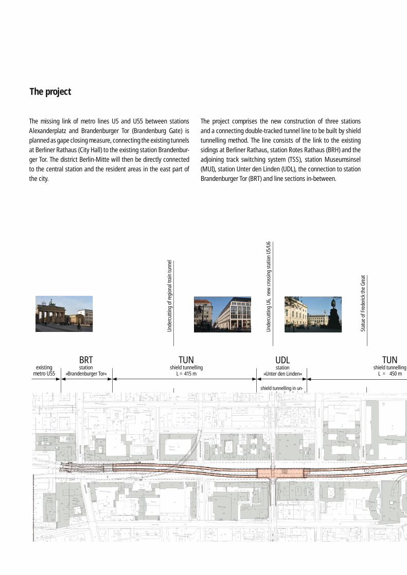
The project
The missing link of metro lines U5 and U55 between stations Alexanderplatz and Brandenburger Tor (Brandenburg Gate) is planned as gape closing measure, connecting the existing tunnels at Berliner Rathaus (City Hall) to the existing station Brandenbur-ger Tor. The district Berlin-Mitte will then be directly connected to the central station and the resident areas in the east part of the city.
The project comprises the new construction of three stations and a connecting double-tracked tunnel line to be built by shield tunnelling method. The line consists of the link to the existing sidings at Berliner Rathaus, station Rotes Rathaus (BRH) and the adjoining track switching system (TSS), station Museumsinsel (MUI), station Unter den Linden (UDL), the connection to station Brandenburger Tor (BRT) and line sections in-between.
Unde
rcut
ting
of re
gion
al tr
ain
tunn
el
Stat
ue o
f Fre
deric
k th
e Gr
eat
Unde
rcut
ting
U6,
new
cro
ssin
g st
atio
n U5
/U6
BRTstation
»Brandenburger Tor«existing
metro U55
UDLstation
»Unter den Linden«
TUNshield tunnelling
L = 415 m
shield tunnelling in un-excavated and undrained
construction pit
TUNshield tunnelling
L = 450 m
exis
ting
met
ro U
6
U5suburban train station

The new metro line runs in two single-tracked tunnels starting at the new station BRH underneath river Spree, underneath the new Berlin Palace (Humboldtforum) currently under reconstruc-tion, underneath Spree Canal and road Unter den Linden leading to the existing station BRT.
The total construction length is around 1.9 km.
Unde
rcut
ting
Lind
en Tu
nnel
Obst
acle
old
woo
den
bore
d pi
le fo
unda
tion
MUIstation
»Museumsinsel«
TSStrack switching
system
TUNTUN shield tunnelling
L = 417 m
plat
form
: bui
lt un
der f
reez
e w
all
acce
ss s
truct
ures
: shi
eld
tunn
ellin
g in
un-
exca
vate
d an
d un
drai
ned
cons
truct
ion
pit
RRHstation
»Berliner Rathaus«existing
metro U5
acce
ss s
truct
ures
: shi
eld
tunn
ellin
g in
un-
exca
vate
d an
d un
drai
ned
cons
truct
ion
pit
Parties involved in the project
Client
Planning joint venture Berliner U-Bahn U5
Berliner VerkehrsbetriebeAnstalt des öffentlichen RechtsBerlin, Germanywww.bvg.de
SSF Ingenieure AG, Consulting Engineers Berlin, Germanywww.ssf-ing.de
ISP Ziviltechniker GmbHVienna, Austriawww.isp-zt.at
Amberg Engineering AGRegensdorf-Watt, Switzerlandwww.amberg.ch
laun
chin
g sh
aft
river Spree
Spree Canal

The line
Undercutting of river Spree and relevant bore profi les
In the area of station MUI the foundation has to be built reaching into the marlstone layers underneath the sands.Large stones and rocks are likely to be encountered during con-struction of the diaphragm walls, jet grouting and shield tun-nelling. The sands are classifi ed as highly abrasive due to their quartz content.The groundwater level lies on average 3 m below the terrain‘s upper surface. Thick sand and melt-water sediments form a continuous and productive aquifer in the inspected area and its surroundings.
The geologyThe district Berlin-Mitte is marked by a glacial valley traversing Berlin from east to west, formed at the end of the last Ice Age, consisting of thick sand and gravel sediments as aquifer. At some points above these layers are organically interspersed sands and peats as well as partially very thick organic silt.
Especially in the area between river Spree and Spree Canal abo-ve the sands, soil layers of sapropel and organically interspersed sands as well as silt can be found, expanding to the excavation cross section of shield tunnelling.

Longitudinal section launching shaft TSS
Shield tunnellingTunnelling starts in the launching shaft at the TSS adjoining sta-tion BRH and ends at station BRT. The tunnels, each 1.6 m long, are built by shield tunnelling method with a tunnel boring machi-ne (TBM) with heading face support by means of a supporting fl uid. The inner diameter of the tunnel galleries is 5.70 m.The tunnel galleries are lined with reinforced concrete tubbings of 35 cm thickness. The conic width of the rings is on average 1.5 m. The tubbing joints are sealed with closed elastomeric frames embedded in a groove and designed for a maximum water pres-sure of 3.0 bar.Drilling of the two galleries is planned by TBM.Construction of the excavation pit for the launching shaft at the TSS is executed by diaphragm wall method with underwater con-crete bottom. The pit wall to be cut through during launching is built with glass fi bre reinforcement in the area of the excavation cross section.
The connecting areas are planned with a redundant sealing sys-tem consisting of a launching cap with lip sealing rings, infl ata-ble emergency sealing and a sealing block (jet grouted) at the earth side of the diaphragm wall.Tunnelling is carried out after construction of the excavation pit enclosure at the ends of stations MUI and UDL before drainage and excavation of the pits.Shield tunnelling will take place underneath the river Spree, the future Berlin Palace, the Spree Canal and the Bertelsmann buil-dings, the Linden Tunnel, the statute of Frederick the Great and the regional train tunnel near road Unter den Linden. Undercut-ting the river and canal requires a ballasting of the water bottom because of the small distance between water bottom and exca-vation cross section of only around 6 m; for ballasting steel slabs or heavy concrete prefabricated elements are used; ship traffi c will be maintained throughout.

Connection »Brandenburger Tor«The tunnel galleries join the eastern pit walls at station Branden-burger Tor. The station was built as reinforced concrete structure erected within diaphragm walls. At the eastern end wall of the station, joint tapes have already been installed and preserved. Together with a transitional block they allow the water-tight con-nection of the tunnel lining to the existing end wall. A jet grouted body of a length of around 6 m is added to the unreinforced dia-phragm wall planned for entry of the TBM.
Dismantling and removing of the TBM is not feasible from the station for reasons of operation and safety, just as it is the case for cutting through from the station side. Therefore, the breakt-hrough of the tunnel gallery into the station can only be done after the TBM has been dismantled.
The TBM cuts into the jet grouted body and the unreinforced dia-phragm wall to a point where a secure waterproofi ng of the TBM is possible. All around the shield skin, under pressurised air, the gap in the cutting area and the shield skin, and, atmospherically, the gap between shield tail and last tubbing ring are sealed.
Before decreasing the pressurised air, a freeze wall has to be built from the ground surface, enabling to seal the water-loaded joint between end wall and reinforced diaphragm wall, the joints of the diaphragm wall‘s ribs caused by construction and the joint between reinforced and unreinforced diaphragm wall. Freezing and temperature measurement bore holes are drilled in two con-secutive rows in the reinforced diaphragm wall as core drillings. Only when all joints are sealed, the TBM can be dismantled.After arriving at station BRT, the TBM is dismantled and trans-ported back to the launching shaft. The shield skin remains. After re-assembly of the TBM, tunnelling of track 2 is started. The TBM is then dismantled and transported in the same way after arriving again at station BRT.
The remaining tunnelling step to break through the diaphragm wall is done manually under a freeze wall; its temperature has to be maintained by arranging freezing pipes at the excavation‘s edges. The joint tapes kept in the end wall are uncovered and concreted into the transitional block of the tunnel‘s inner shell. Afterwards the tunnel is broken through to the existing station.
Connections construction stage 2
Construction process phase 2Entry TBM into diaphragm wall
– relief bore hole – creation of freeze wall by operating fi rst row of
freezing borings – after de-freezing phase, entry of TBM through
unreinforced diaphragm wall until reinforcement of second diaphragm wall

Construction in inner-urban areaNew construction of underground U5 in the centre of Berlin re-quires, in addition to structural and technological particularities of undercutting bodies of water and the proximity to existing buildings, supplementary measures, especially in terms of const-ruction site clearing and traffi c management during construction as well as logistics planning. Examples are the area of the new
crossing station Unter den Linden and the crossing of the Spree including a port of transhipment for construction materials.To maintain individual traffi c on road Unter den Linden and to guarantee unrestricted accessibility to surrounding buildings, construction has to be accomplished section-wise by construc-tion lots.
plan of cables / utilities lot station UDL

The stations
Station »Berliner Rathaus«Station BRH is situated in direct vicinity to Berlin‘s Red City Hall. It comprises the connection to the sidings in the currently opera-ted tunnel of the existing parts of U5. In the following course of the line in direction west, the TSS is planned.As it is necessary to maintain individual traffi c on Spandauer Straße construction is planned in two sections.The fi rst section consists mainly of the TSS, the second one of station BRH.
Track switching systemAt the west end of the TSS, a gate will be arranged in a weir chamber during construction works, so that in case of an ac-cident in the area where the underground tunnel crosses river Spree, the eastern parts of the installation are protected from fl ooding. In the area of the weir chamber and the adjoining blocks, the launching shaft for tunnelling is arranged.The TSS is built in cut-and-cover method with diaphragm walls and an underwater concrete bottom anchored with injection piles.
The TSS is a partially two-storey (weir chamber and adjoining blocks), partially single-storey (at the transition to station BRH) structure.
StationThe station consists of three levels: - The lower level of the station is connected to the lower level of
the existing tunnel. Four tracks of the old tunnel are led into the new station and will there be used as sidings, replacing the sidings in the old tunnel.
- The lateral platforms of U5 are at a depth of around 7 m underneath ground level.
- With aisles and escalators the connection of the mezzanine fl oor and station exits is guaranteed.
- The mezzanine fl oor spans the platforms of the east and west areas of the station and links the lateral platforms of U5 to each other.
left: Station »Berliner Rathaus« cross section track switching systemright: Station »Berliner Rathaus« cross section station

Safety considerations led to the division of the structure into se-veral construction lots.Construction is executed partially in cut-and-cover method with diaphragm wall enclosure, a deep jet grouted bottom and stif-fening grid just underneath the excavation pit bottom. Levels of stiffeners and anchors support the diaphragm walls.To minimise emissions at the city hall, top-down construction is used by applying diaphragm walls and primary supports.The tight and at the same time electronically insulating connec-tion of station BRH to the existing tunnel is accomplished by me-ans of underground injections. The bituminous sealing tapes of the existing tunnel are connected with great care.
Some particularities are: - The arrangement of the exit situations has to be done in
consideration of archaeological fi ndings. - The arrangement of an ‚archaeological window‘ is prepared. - The envisaged design of the platform halls with impressive
mushroom columns is a demanding concept.
- Due to the surrounding buildings, covers have to be low and slendernesses high.
- The later following connection of line U3 is taken account of.
Station »Museumsinsel«The station starts at the east bank of the Spree Canal and fi ni-shes in the area of Kronprinzenpalais. The structure comprises two station ends of a maximum length of 43 m with accesses and mezzanine fl oors as well as the platform areas.The station ends are built in top-down method with enclosing diaphragm walls and a deep jet grouted bottom. In addition, a jet grouted stiffening grid is planned underneath the excavation bottom. Intermediate stiffeners are implemented as steel const-ructions.Tunnelling with the TBM is done analogous to tunnelling in the area TSS.The platform hall is in the area of Spree Canal and is constructed under a freeze wall by shotcrete method after breakthrough of the tunnel boring machine. The minimum cover between freeze
»Station Museumsinsel« cross section platform area and freeze wall
existing building »Kommandantur« bridge
»Schlossbrücke«road Schinkelstraße
Ground freezing as per preset pattern according to the construction process

Station »Unter den Linden«At station UDL the new line U5 crosses the existing U6. To cons-truct the new crossing station, the existing tunnel of line U6 has to be demolished in some areas and be rebuilt together with one of the platform areas and the new interchange situation between U6 and U5.The T-shaped crossing station runs from east to west underneath road Unter den Linden (U5) and from north to south underneath road Friedrichstraße (U6). As it is necessary to maintain road traf-fi c, station UDL is divided in different construction lots.For construction of the crossing area between U5 and U6 and new construction of the platform areas of U6, Friedrichstraße has to be closed for 12 month. Successively, operation of U6 has to be interrupted for around 16 month.The new part of U6 is built in top-down method with diaphragm wall enclosure and deep jet grouted bottom as well as a jet grouted stiffening grid underneath the excavation bottom. Due
wall and bottom of the Spree Canal is around 4.50 m. The freeze wall is created from both station ends by drillings of 85 m length (controlled) and 25 m (uncontrolled).The designed structural thickness of the freeze wall is 2.0 m.
The platform hall is excavated in a three-cell cross section, con-sisting of one centre and two lateral galleries. First, the centre gallery is excavated by graded full-face cutting with rapidly following bottom closure by shotcrete grouting. The structure is then completed in the area of the centre gallery. Afterwards, the lateral galleries are built in the same way. Tunnelling of the lateral galleries is implemented during a cross section widening of the already built shield tunnelling area, whilst parts of the tubbing tubes are continually demolished. The reinforced inner shells are then built in the lateral galleries and connected force-fi t to the shell of the centre gallery.
Station »Unter den Linden« cross section new construction component for existing metro U6
existing »Lindencorso«existing »Hotel Westin Grand«
road Friedrichstraße

to simultaneous demolition of the existing underground tunnel, construction has to be divided in stages.The station of U5 is also constructed in top-down method with diaphragm walls and a deep jet grouted bottom as well as a jet grouted stiffening grid underneath the excavation bottom. The depth of the diaphragm walls of up to 35 m is quite remarkable. The structure of the station required the arrangement of individu-al blocks, which are joint-less on a length of up to 80 m.
To maintain individual road traffi c on Unter den Linden and to ensure accessibility to adjacent buildings, a section-wise realisa-tion in the above mentioned lots is necessary.
The TBM runs through the station after construction of the pit enclosure and the cover of U5, and after construction of the new section of U6. Underground operation of U6 will then already have been resumed.The excavation pits are not excavated or drained at this moment. To securely seal the joints, jet grouted columns are built at the outside of the fi nal diaphragm walls; the joint between dia-phragm wall and tubbing ring is grouted afterwards. On track 2 , the TBM cuts through an area where there are anchors and grout bodies in old construction pits of surrounding buildings. They are drilled through and the anchor parts are removed before shield tunnelling.
road Unter den Linden
Station »Unter den Linden« cross section of crossing area – new metro U5 with existing metro U6

SSF Ingenieure AGConsulting Engineers
MunichBerlin Halle Cologne
www.ssf - ing.de
pict
ure
cred
its:
SSF
Inge
nieu
re A
G / P
G U5
, Pho
togr
aphs
: S. O
mm
ert