New coating demands for the centrifugal casting of cylinder liners · 2019-08-21 · The problem of...
6
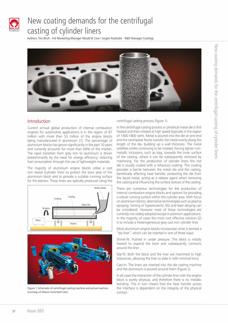
37 Issue 265 Introduction Current annual global production of internal combustion engines for automotive applications is in the region of 87 million with more than 53 million of the engine blocks being manufactured in aluminium [1]. The percentage of aluminium blocks has grown significantly in the past 10 years and currently accounts for more than 60% of the market. The rapid transition from grey iron to aluminium is driven predominantly by the need for energy efficiency; reducing fuel consumption through the use of lightweight materials. The majority of aluminium engine blocks utilise a cast iron sleeve (cylinder liner) to protect the bore area of the aluminium block and to provide a suitable running surface for the pistons. These liners are typically produced using the centrifugal casting process (figure 1). In the centrifugal casting process a cylindrical metal die is first heated and then rotated at high speed (typically in the region of 1400-1800 rpm). Metal is poured into the die at one end and the centripetal forces transfer the metal evenly along the length of the die, building up a wall thickness. The metal solidifies whilst continuing to be rotated, forcing lighter non- metallic inclusions, such as slag, towards the inner surface of the casting, where it can be subsequently removed by machining. For the production of cylinder liners the hot die is usually coated with a refractory coating. This coating provides a barrier between the metal die and the casting, beneficially affecting heat transfer, protecting the die from the liquid metal, acting as a release agent when removing the casting and influencing the surface texture of the casting. There are numerous technologies for the production of internal combustion engine blocks and options for providing a robust running surface within the cylinder area. With focus on aluminium blocks; alternative technologies such as plasma spraying, honing of hypereutectic AlSi and laser alloying can be considered. However most of these technologies are currently not widely adopted except in premium applications. In the majority of cases the most cost effective solution [2] is to include a (heterogeneous) grey cast iron cylinder liner. Most aluminium engine blocks incorporate what is termed a “dry liner”, which can be inserted in one of three ways: Shrink-fit: Pushed in under pressure. The block is initially heated to expand the bore and subsequently contracts around the liner Slip-fit: Both the block and the liner are machined to high tolerances, allowing the liner to slide in with minimal force Cast-in: The liners are inserted into the die casting machine and the aluminium is poured around them (Figure 2) In all cases the interaction of the cylinder liner with the engine block is purely physical, and therefore there is no metallic bonding. This in turn means that the heat transfer across the interface is dependent on the integrity of the physical contact. New coating demands for the centrifugal casting of cylinder liners New coating demands for the centrifugal casting of cylinder liners Figure 1. Schematic of centrifugal casting machine and actual machine (courtesy of Gibson Centritech Ltd.) Molten Metal Rotation Metal Die Rollers Motor Coating Casting Authors: Tim Birch - Intl Marketing Manager Mould & Core / Jurgen Radstake - R&D Manager Coatings
Transcript of New coating demands for the centrifugal casting of cylinder liners · 2019-08-21 · The problem of...
CMYKGrey : 0 / 0 / 0 /85Red : 0 / 100 / 96 / 0
37 Issue 265
Introduction
Current annual global production of internal combustion engines for automotive applications is in the region of 87 million with more than 53 million of the engine blocks being manufactured in aluminium [1]. The percentage of aluminium blocks has grown significantly in the past 10 years and currently accounts for more than 60% of the market. The rapid transition from grey iron to aluminium is driven predominantly by the need for energy efficiency; reducing fuel consumption through the use of lightweight materials.
The majority of aluminium engine blocks utilise a cast iron sleeve (cylinder liner) to protect the bore area of the aluminium block and to provide a suitable running surface for the pistons. These liners are typically produced using the
centrifugal casting process (figure 1).
In the centrifugal casting process a cylindrical metal die is first heated and then rotated at high speed (typically in the region of 1400-1800 rpm). Metal is poured into the die at one end and the centripetal forces transfer the metal evenly along the length of the die, building up a wall thickness. The metal solidifies whilst continuing to be rotated, forcing lighter non-metallic inclusions, such as slag, towards the inner surface of the casting, where it can be subsequently removed by machining. For the production of cylinder liners the hot die is usually coated with a refractory coating. This coating provides a barrier between the metal die and the casting, beneficially affecting heat transfer, protecting the die from the liquid metal, acting as a release agent when removing the casting and influencing the surface texture of the casting.
There are numerous technologies for the production of internal combustion engine blocks and options for providing a robust running surface within the cylinder area. With focus on aluminium blocks; alternative technologies such as plasma spraying, honing of hypereutectic AlSi and laser alloying can be considered. However most of these technologies are currently not widely adopted except in premium applications. In the majority of cases the most cost effective solution [2] is to include a (heterogeneous) grey cast iron cylinder liner.
Most aluminium engine blocks incorporate what is termed a “dry liner”, which can be inserted in one of three ways:
Shrink-fit: Pushed in under pressure. The block is initially heated to expand the bore and subsequently contracts around the liner
Slip-fit: Both the block and the liner are machined to high tolerances, allowing the liner to slide in with minimal force
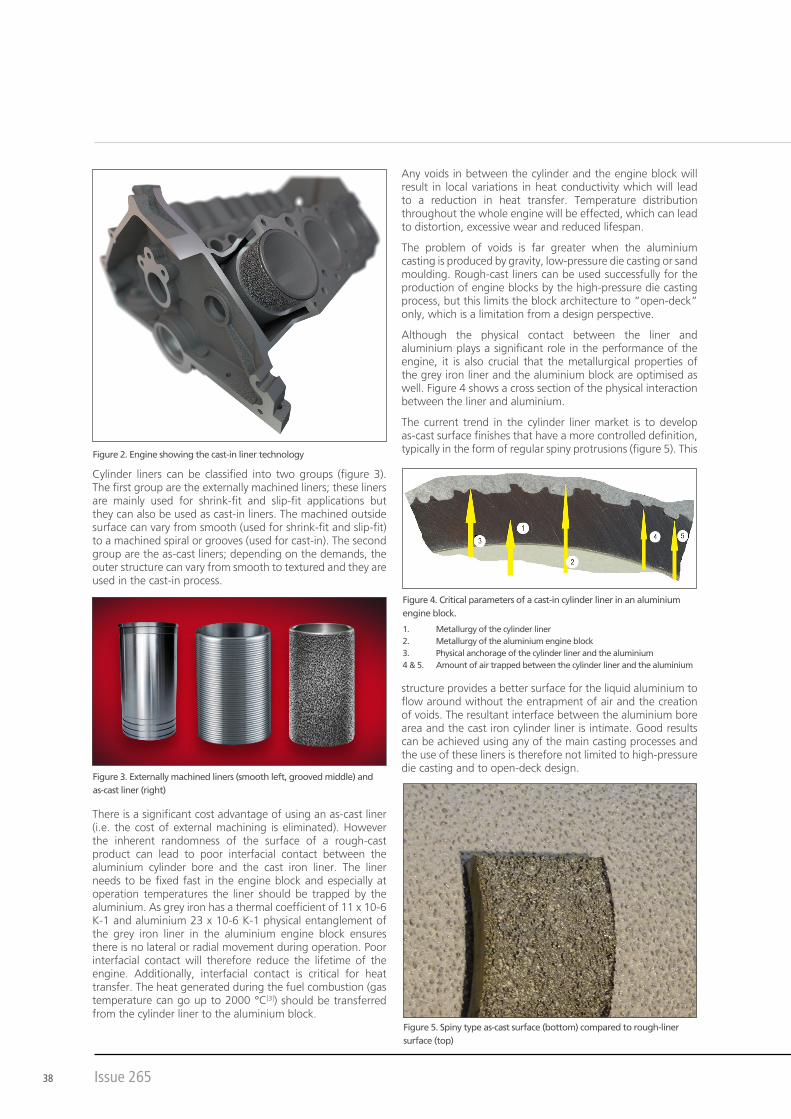
Cast-in: The liners are inserted into the die casting machine and the aluminium is poured around them (Figure 2)
In all cases the interaction of the cylinder liner with the engine block is purely physical, and therefore there is no metallic bonding. This in turn means that the heat transfer across the interface is dependent on the integrity of the physical contact.
New coating demands for the centrifugal casting of cylinder liners
New
coating demands for the centrifugal casting of cylinder liners
Figure 1. Schematic of centrifugal casting machine and actual machine (courtesy of Gibson Centritech Ltd.)
Molten Metal
RotationMetal Die
RollersMotor
CoatingCasting
Authors: Tim Birch - Intl Marketing Manager Mould & Core / Jurgen Radstake - R&D Manager Coatings
38 Issue 265
Any voids in between the cylinder and the engine block will result in local variations in heat conductivity which will lead to a reduction in heat transfer. Temperature distribution throughout the whole engine will be effected, which can lead to distortion, excessive wear and reduced lifespan.
The problem of voids is far greater when the aluminium casting is produced by gravity, low-pressure die casting or sand moulding. Rough-cast liners can be used successfully for the production of engine blocks by the high-pressure die casting process, but this limits the block architecture to “open-deck” only, which is a limitation from a design perspective.
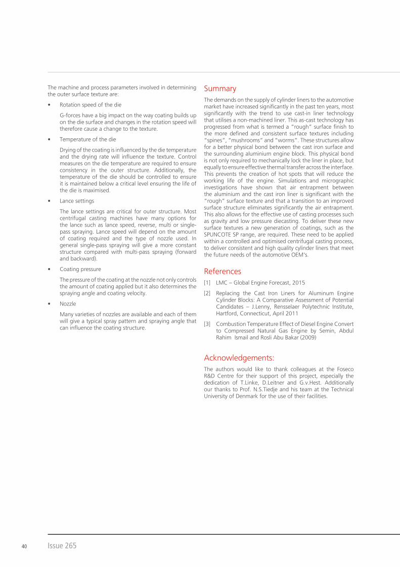
Although the physical contact between the liner and aluminium plays a significant role in the performance of the engine, it is also crucial that the metallurgical properties of the grey iron liner and the aluminium block are optimised as well. Figure 4 shows a cross section of the physical interaction between the liner and aluminium.
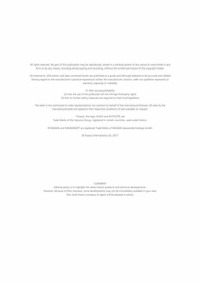
The current trend in the cylinder liner market is to develop as-cast surface finishes that have a more controlled definition, typically in the form of regular spiny protrusions (figure 5). This
structure provides a better surface for the liquid aluminium to flow around without the entrapment of air and the creation of voids. The resultant interface between the aluminium bore area and the cast iron cylinder liner is intimate. Good results can be achieved using any of the main casting processes and the use of these liners is therefore not limited to high-pressure die casting and to open-deck design.
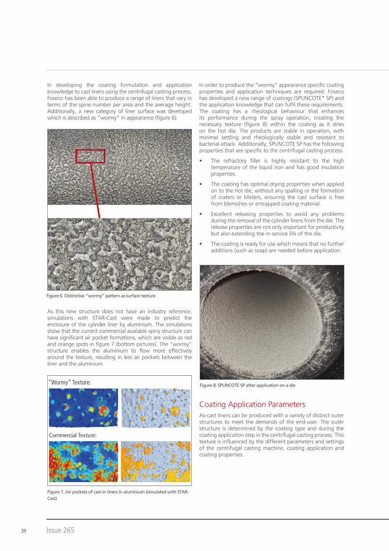
Cylinder liners can be classified into two groups (figure 3). The first group are the externally machined liners; these liners are mainly used for shrink-fit and slip-fit applications but they can also be used as cast-in liners. The machined outside surface can vary from smooth (used for shrink-fit and slip-fit) to a machined spiral or grooves (used for cast-in). The second group are the as-cast liners; depending on the demands, the outer structure can vary from smooth to textured and they are used in the cast-in process.
There is a significant cost advantage of using an as-cast liner (i.e. the cost of external machining is eliminated). However the inherent randomness of the surface of a rough-cast product can lead to poor interfacial contact between the aluminium cylinder bore and the cast iron liner. The liner needs to be fixed fast in the engine block and especially at operation temperatures the liner should be trapped by the aluminium. As grey iron has a thermal coefficient of 11 x 10-6 K-1 and aluminium 23 x 10-6 K-1 physical entanglement of the grey iron liner in the aluminium engine block ensures there is no lateral or radial movement during operation. Poor interfacial contact will therefore reduce the lifetime of the engine. Additionally, interfacial contact is critical for heat transfer. The heat generated during the fuel combustion (gas temperature can go up to 2000 °C[3]) should be transferred from the cylinder liner to the aluminium block.
Figure 2. Engine showing the cast-in liner technology
Figure 3. Externally machined liners (smooth left, grooved middle) and as-cast liner (right)
Figure 4. Critical parameters of a cast-in cylinder liner in an aluminium engine block.
1. Metallurgy of the cylinder liner2. Metallurgy of the aluminium engine block3. Physical anchorage of the cylinder liner and the aluminium4 & 5. Amount of air trapped between the cylinder liner and the aluminium
Figure 5. Spiny type as-cast surface (bottom) compared to rough-liner surface (top)
39 Issue 265
In developing the coating formulation and application knowledge to cast liners using the centrifugal casting process, Foseco has been able to produce a range of liners that vary in terms of the spine number per area and the average height. Additionally, a new category of liner surface was developed which is described as “wormy” in appearance (figure 6).
As this new structure does not have an industry reference, simulations with STAR-Cast were made to predict the enclosure of the cylinder liner by aluminium. The simulations show that the current commercial available spiny structure can have significant air pocket formations, which are visible as red and orange spots in figure 7 (bottom pictures). The “wormy” structure enables the aluminium to flow more effectively around the texture, resulting in less air pockets between the liner and the aluminium.
Figure 7. Air pockets of cast-in liners in aluminium (simulated with STAR-Cast)
Figure 6. Distinctive “wormy” pattern as surface texture
In order to produce the “wormy” appearance specific coating properties and application techniques are required. Foseco has developed a new range of coatings (SPUNCOTE* SP) and the application knowledge that can fulfil these requirements. The coating has a rheological behaviour that enhances its performance during the spray operation, creating the necessary texture (figure 8) within the coating as it dries on the hot die. The products are stable in operation, with minimal settling and rheologically stable and resistant to bacterial attack. Additionally, SPUNCOTE SP has the following properties that are specific to the centrifugal casting process:
• The refractory filler is highly resistant to the high temperature of the liquid iron and has good insulation properties.
• The coating has optimal drying properties when applied on to the hot die, without any spalling or the formation of craters or blisters, ensuring the cast surface is free from blemishes or entrapped coating material.
• Excellent releasing properties to avoid any problems during the removal of the cylinder liners from the die. The release properties are not only important for productivity but also extending the in-service life of the die.
• The coating is ready for use which means that no further additions (such as soap) are needed before application.
Coating Application ParametersAs-cast liners can be produced with a variety of distinct outer structures to meet the demands of the end-user. The outer structure is determined by the coating type and during the coating application step in the centrifugal casting process. This texture is influenced by the different parameters and settings of the centrifugal casting machine, coating application and coating properties.
Figure 8. SPUNCOTE SP after application on a die
40 Issue 265
The machine and process parameters involved in determining the outer surface texture are:
• Rotation speed of the die
G-forces have a big impact on the way coating builds up on the die surface and changes in the rotation speed will therefore cause a change to the texture.
• Temperature of the die
Drying of the coating is influenced by the die temperature and the drying rate will influence the texture. Control measures on the die temperature are required to ensure consistency in the outer structure. Additionally, the temperature of the die should be controlled to ensure it is maintained below a critical level ensuring the life of the die is maximised.
• Lance settings
The lance settings are critical for outer structure. Most centrifugal casting machines have many options for the lance such as lance speed, reverse, multi or single-pass spraying. Lance speed will depend on the amount of coating required and the type of nozzle used. In general single-pass spraying will give a more constant structure compared with multi-pass spraying (forward and backward).
• Coating pressure
The pressure of the coating at the nozzle not only controls the amount of coating applied but it also determines the spraying angle and coating velocity.
• Nozzle
Many varieties of nozzles are available and each of them will give a typical spray pattern and spraying angle that can influence the coating structure.
SummaryThe demands on the supply of cylinder liners to the automotive market have increased significantly in the past ten years, most significantly with the trend to use cast-in liner technology that utilises a non-machined liner. This as-cast technology has progressed from what is termed a “rough” surface finish to the more defined and consistent surface textures including “spines”, “mushrooms” and “worms”. These structures allow for a better physical bond between the cast iron surface and the surrounding aluminium engine block. This physical bond is not only required to mechanically lock the liner in place, but equally to ensure effective thermal transfer across the interface. This prevents the creation of hot spots that will reduce the working life of the engine. Simulations and micrographic investigations have shown that air entrapment between the aluminium and the cast iron liner is significant with the “rough” surface texture and that a transition to an improved surface structure eliminates significantly the air entrapment. This also allows for the effective use of casting processes such as gravity and low pressure diecasting. To deliver these new surface textures a new generation of coatings, such as the SPUNCOTE SP range, are required. These need to be applied within a controlled and optimised centrifugal casting process, to deliver consistent and high quality cylinder liners that meet the future needs of the automotive OEM’s.
References[1] LMC – Global Engine Forecast, 2015
[2] Replacing the Cast Iron Liners for Aluminum Engine Cylinder Blocks: A Comparative Assessment of Potential Candidates – J.Lenny, Rensselaer Polytechnic Institute, Hartford, Connecticut, April 2011
[3] Combustion Temperature Effect of Diesel Engine Convert to Compressed Natural Gas Engine by Semin, Abdul Rahim Ismail and Rosli Abu Bakar (2009)
Acknowledgements:The authors would like to thank colleagues at the Foseco R&D Centre for their support of this project, especially the dedication of T.Linke, D.Leitner and G.v.Hest. Additionally our thanks to Prof. N.S.Tiedje and his team at the Technical University of Denmark for the use of their facilities.
All rights reserved. No part of this publication may be reproduced, stored in a retrieval system of any nature or transmitted in anyform or by any means, including photocopying and recording, without the written permission of the copyright holder.
All statements, information and data contained herein are published as a guide and although believed to be accurate and reliable(having regard to the manufacturer’s practical experience) neither the manufacturer, licensor, seller nor publisher represents or
warrants, expressly or impliedly:
(1) their accuracy/reliability(2) that the use of the product(s) will not infringe third party rights
(3) that no further safety measures are required to meet local legislation
The seller is not authorised to make representations nor contract on behalf of the manufacturer/licensor. All sales by themanufacturer/seller are based on their respective conditions of sale available on request.
*Foseco, the logo, SEDEX and ACTICOTE are Trade Marks of the Vesuvius Group, registered in certain countries, used under licence.
® MAGMA and MAGMASOFT are registered Trade Marks of MAGMA Giesserei technologie GmbH.
© Foseco International Ltd. 2017
COMMENTEditorial policy is to highlight the latest Foseco products and technical developments.
However, because of their newness, some developments may not be immediately available in your area.Your local Foseco company or agent will be pleased to advise.

Foseco International LimitedP.O. Box 5516
TamworthStaffordshire
England B78 3XQRegistered in England No. 468147
ISSN 0266 9994
Produced in Germany
400121428