NEW cavity fl oor boxes building on success · 2019-10-13 · NEW cavity fl oor boxes... building...
45
NEW cavity floor boxes... building on success Legrand’s new range of cavity floor boxes offer a modular product that is simpler to order. Components are sold separately enabling any configuration to be accommodated on site. Available in 1, 2, 3 and 4 compartments and three depths - the new range has been developed with a host of special features: • Rapid fit and remove mechanism • Reversible lid • Push fit detail to secure base in the floor • 1 compartment floor box is designed to better accommodate moulded plugs Full range of module and accessory plates Bespoke metal trims are available in any RAL reference to suit a building’s design scheme 8
Transcript of NEW cavity fl oor boxes building on success · 2019-10-13 · NEW cavity fl oor boxes... building...

NEW cavity fl oor boxes...building on successLegrand’s new range of cavity fl oor boxes offer a modular product that is simpler to order. Components are sold separately enabling any confi guration to be accommodated on site.
Available in 1, 2, 3 and 4 compartments and three depths - the new range has been developed with a host of special features:
• Rapid fit and remove mechanism
• Reversible lid
• Push fit detail to secure base in the floor
• 1 compartment floor box is designed to better accommodate moulded plugs
Full range of module and accessory plates Bespoke metal trims are available in any RAL reference to suit a building’s design schemeBespoke metal trims are available in any RAL reference to Full range of module and accessory plates
8
Feature Pages.indd 8 21/09/2012 17:59

Rapid fi t push lock secures base in fl oor apertureInter-compartment knockouts
Full range of power and data module plates
Durabable ABS trim and lid surround
Reversible lid
Rapid fi t /remove mechanism adjusts for fl ooring thickness
Removable base for easy wiring20mm and 25mm knockouts
2 cable outlets with sponge foam to prevent ingress
9
Feature Pages.indd 9 21/09/2012 18:01

10
No. of compartments 1 compartment 2 compartment 3 compartment 4 compartment
Floor box base
Cavityfloorboxbase75mmdeep – CAV275 CAV375 CAV475
Depth Cavityfloorboxbase85mmdeep CAV185 CAV285 CAV385 CAV485
Cavityfloorboxbase110mmdeep – CAV2110 CAV3110 CAV4110
Socket outlet plates
13Atwinswitchedsocketplate SP3201 SP3201 SP3201 SP4201
13Atwinunswitchedsocketplate SP3200 SP3200 SP3200 SP4200
13 A standard 13Atwinswitchedcleanearthsocketplate SP3211 SP3211 SP3211 SP4211
13Atripleunswitchedsocketplate SP3300 SP3300 SP3300 SP4300
13Atripleunswitchedcleanearthsocketplate SP3310 SP3310 SP3310 SP4310
13AtwinNSswitchedsocketplate SP3221 SP3221 SP3221 SP4221
13 A non-standard 13AtwinNSunswitchedsocketplate SP3220 SP3220 SP3220 SP4220
13AtwinNSswitchedcleanearthsocketplate SP3231 SP3231 SP3231 SP4231
RCD
2gangRCDsocketplate SP3202 SP3202 SP3202 SP4202
2gangRCDsocketplate–cleanearth SP3212 SP3212 SP3212 SP4212
37x22mm–2cut-outplate SP3203 SP3203 SP3203 SP4203
37x22mm–4cut-outplate SP3403 SP3403 SP3403 SP4403
Data 37x22mm–4cut-outwaveplate SP3404 SP3404 SP3404 SP4404
37x22mm–6cut-outplate SP3603 SP3603 SP3603 SP4603
47·5x23·5mm–4cut-outplate SP3408 SP3408 SP3408 SP4408
2xstandardsingleoutlet60·3mm SP3205 SP3205 SP3205 –
Standard2gangoutletplate120·6mm SP3105 SP3105 SP3105 –
50x50mm–1cut-outplate SP3106 SP3106 SP3106 SP4106
General 50x50mm–2cut-outplate SP3206 SP3206 SP3206 SP4206
Blankplate SP3000 SP3000 SP3000 SP4000
58x53·5mm–1cut-outplatetoacceptArteormountingframe(1) SP3107 SP3107 SP3107 SP4107
58x53·5mm–2cut-outplatetoaccept2xArteormountingframes(1) SP3207 SP3207 SP3207 SP4207
Lids and trims
ABSwithcarpettrim–6mmrecess – FBL2ABS FBL3ABS FBL3ABS
Combinationwithedgetrim–6mmrecess – FBL2COM FBL3COM FBL3COM
Metal,powdercoatedwithcarpettrim–6mmrecess FBL1MCT FBL2MCT FBL3MCT FBL3MCT
Metal,powdercoatedwithedgetrim–10mmrecess FBL1MET FBL2MET FBL3MET FBL3MET
Stainlesssteelwithcarpettrim–6mmrecess FBL1SCT FBL2SCT FBL3SCT FBL3SCT
Stainlesssteelwithedgetrim–10mmrecess FBL1SET FBL2SET FBL3SET FBL3SET
Brasswithcarpettrim–6mmrecess FBL1BCT FBL2BCT FBL3BCT FBL3BCT
Brasswithedgetrim–10mmrecess FBL1BET FBL2BET FBL3BET FBL3BET
cavity floor service outlet boxesselection chart
NEW
(1)ForArteormountingframes,refertothelatestWiringDevicescatalogue
010_011_Floor_2012 v4.indd 10 21/09/2012 14:28

11
No. of compartments 1 compartment 2 compartment 3 compartment 4 compartment
Floor box base
Cavityfloorboxbase75mmdeep – CAV275 CAV375 CAV475
Depth Cavityfloorboxbase85mmdeep CAV185 CAV285 CAV385 CAV485
Cavityfloorboxbase110mmdeep – CAV2110 CAV3110 CAV4110
Socket outlet plates
13Atwinswitchedsocketplate SP3201 SP3201 SP3201 SP4201
13Atwinunswitchedsocketplate SP3200 SP3200 SP3200 SP4200
13 A standard 13Atwinswitchedcleanearthsocketplate SP3211 SP3211 SP3211 SP4211
13Atripleunswitchedsocketplate SP3300 SP3300 SP3300 SP4300
13Atripleunswitchedcleanearthsocketplate SP3310 SP3310 SP3310 SP4310
13AtwinNSswitchedsocketplate SP3221 SP3221 SP3221 SP4221
13 A non-standard 13AtwinNSunswitchedsocketplate SP3220 SP3220 SP3220 SP4220
13AtwinNSswitchedcleanearthsocketplate SP3231 SP3231 SP3231 SP4231
RCD
2gangRCDsocketplate SP3202 SP3202 SP3202 SP4202
2gangRCDsocketplate–cleanearth SP3212 SP3212 SP3212 SP4212
37x22mm–2cut-outplate SP3203 SP3203 SP3203 SP4203
37x22mm–4cut-outplate SP3403 SP3403 SP3403 SP4403
Data 37x22mm–4cut-outwaveplate SP3404 SP3404 SP3404 SP4404
37x22mm–6cut-outplate SP3603 SP3603 SP3603 SP4603
47·5x23·5mm–4cut-outplate SP3408 SP3408 SP3408 SP4408
2xstandardsingleoutlet60·3mm SP3205 SP3205 SP3205 –
Standard2gangoutletplate120·6mm SP3105 SP3105 SP3105 –
50x50mm–1cut-outplate SP3106 SP3106 SP3106 SP4106
General 50x50mm–2cut-outplate SP3206 SP3206 SP3206 SP4206
Blankplate SP3000 SP3000 SP3000 SP4000
58x53·5mm–1cut-outplatetoacceptArteormountingframe(1) SP3107 SP3107 SP3107 SP4107
58x53·5mm–2cut-outplatetoaccept2xArteormountingframes(1) SP3207 SP3207 SP3207 SP4207
Lids and trims
ABSwithcarpettrim–6mmrecess – FBL2ABS FBL3ABS FBL3ABS
Combinationwithedgetrim–6mmrecess – FBL2COM FBL3COM FBL3COM
Metal,powdercoatedwithcarpettrim–6mmrecess FBL1MCT FBL2MCT FBL3MCT FBL3MCT
Metal,powdercoatedwithedgetrim–10mmrecess FBL1MET FBL2MET FBL3MET FBL3MET
Stainlesssteelwithcarpettrim–6mmrecess FBL1SCT FBL2SCT FBL3SCT FBL3SCT
Stainlesssteelwithedgetrim–10mmrecess FBL1SET FBL2SET FBL3SET FBL3SET
Brasswithcarpettrim–6mmrecess FBL1BCT FBL2BCT FBL3BCT FBL3BCT
Brasswithedgetrim–10mmrecess FBL1BET FBL2BET FBL3BET FBL3BET
cavity floor service outlet boxesselection chart
010_011_Floor_2012 v4.indd 11 21/09/2012 14:11
12
cavity floor service outlet boxes
Pack Cat.Nos. Cavity floor boxes
Contractor floor box
SuppliedemptyReadytoacceptstandardBStwogangwiringaccessoriesAdditionalmountingplatesnotrequiredRecommendedholecut-outsize:302-304mmx219-221mm7mmlidrecessStandarddepth:85mm20/25mmknockoutstoeachcompartmentManufacturedfrompre-galvanisedsteeltoBSEN10142and3,andpolycarbonate/ABS
1 CB3 3compartmentcontractorfloorbox
Floor box bases
SuppliedemptyLidsandtrimsaredetailedonp.13Outletplatesaredetailedonp.13
1 compartment floor box base
Recommendedholecut-outsize:165-167mmx203-205mm
1 CAV185 85mmdeep
2 compartment floor box base
Recommendedholecut-outsize:263-265mmx203-205mm
1 CAV275 75mmdeep 1 CAV285 85mmdeep 1 CAV2110 110mmdeep
picto loupe-65765j.eps
Cavity floor service outlet boxes selection chart (p. 10-11) Dimensions and technical information (p. 16)
Floor boxes with built-in RCD and RCBOs are also available
Contact us on +44 (0) 870 608 9020
Cavity floor boxes and slab boxes are available pre-wired to tap-offs
see p. 15
Pack Cat.Nos. Cavity floor boxes (continued)
3 compartment floor box base
Recommendedholecut-outsize:340-342mmx203-205mm
1 CAV375 75mmdeep 1 CAV385 85mmdeep 1 CAV3110 110mmdeep
4 compartment floor box base
Recommendedholecut-outsize:340-342mmx203-205mm
1 CAV475 75mmdeep 1 CAV485 85mmdeep 1 CAV4110 110mmdeep
Slab floor box
1 SLAB1 1compartment 1 SLAB2 2compartment 1 SLAB3 3compartment 1 SLAB4 4compartment
CB3
CAV4110
CAV385
CAV285
CAV185
NEW
012_Floor_2012 v4.indd 12 21/09/2012 14:13
13
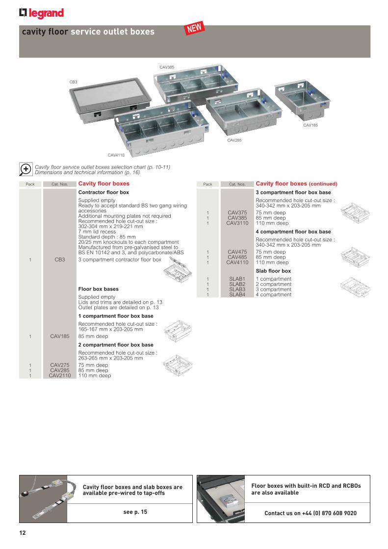
Pack Cat.Nos. Poweranddataplates
1,2,3comp. 4comp. 100mmwide 75mmwide
13Astandardsocketplates 1 SP3201 SP4201 Twinswitched 1 SP3200 SP4200 Twinunswitched
socketplate 1 SP3211 SP4211 Twinswitchedcleanearth 1 SP3300 SP4300 Tripleunswitched 1 SP3310 SP4310 Tripleunswitched
cleanearth
13Anon-standardsocketplates 1 SP3221 SP4221 TwinNSswitched 1 SP3220 SP4220 TwinNSunswitched 1 SP3231 SP4231 TwinNSswitched
cleanearth
RCDsocketplates 1 SP3202 SP4202 2gang 1 SP3212 SP4212 2gang–cleanearth
Dataplates 1 SP3203 SP4203 37x22mm–2cut-outs 1 SP3403 SP4403 37x22mm–4cut-outs
1 SP3404 SP4404 37x22mm–4cut-outs(waveplate)
1 SP3603 SP4603 37x22mm–6cut-outs 1 SP3408 SP4408 47·5x23·5mm–4cut-outs
General 1 SP3205 - 2xstandardsingleoutlet60·3mm 1 SP3105 - Standard2gang
outletplate120·6mm 1 SP3106 SP4106 50x50mm–
1cut-outplate 1 SP3206 SP4206 50x50mm–
2cut-outplate 1 SP3000 SP4000 Blankplate 1 SP3107 SP4107 58x53·5mm–1cut-out
platetoacceptArteormountingframe(Cat.No.576016)(1)
1 SP3207 SP4207 58x53·5mm–2cut-outsplatetoaccept2xArteormountingframes(Cat.No.576016)(1)
Fasteners 50 SPSCREW M3·5x6sparesocketplatescrews
picto loupe-65765j.eps
Dimensions and technical information (p. 16) Cavity floor outlet boxes selection chart (p. 10-11) Installation details (p. 17)
Platestofit1,2and3compartmentboxesareall100mmwide4compartmentplatesare75mmwideNon-standardsocketshavearoundearthpinDuetooveralldepth,RCDsocketsandwavetypedataplateswillNOTfitintheflushfloorandshallowflushfloorranges(Cat.Nos.FFO/AFS)Whenusingwithunderfloorductsystems(Cat.No.AFU)theoutletboxmustberaisedby8mmfromthelowestpointtoallowforwiring
outlet plates for floor boxespower and data
lids and trims for floor boxes
picto loupe-65765j.eps
Dimensions and technical information (p. 16) Cavity floor outlet boxes selection chart (p. 10-11) Installation details (p. 17)
MouldedlidsandtrimsaremanufacturedfromdurableABSandfeatureaquickfit/releaseratchetsystemCarpettrimversionsaresuppliedwitha6mmcarpetrecessEdgetrimversionsaresuppliedwitha10mmrecessMetaltrimversionsarepowdercoatedgreyRAL7024mattasstandardStainlesssteelissatinfinishasstandardBrassispolishedfinishasstandard
Metal lids and trims can be powder coated to any RAL reference. Other options, such as lockable lids, are available to special order
Contact us on +44 (0) 870 608 9020(1)ForArteormountingframes,refertothelatest
WiringDevicescatalogue
Pack Cat.Nos. Floorboxlidsandtrims
1and2compartment 1comp. 2comp. Carpettrim 1 – FBL2ABS ABS 1 FBL1MCT FBL2MCT Metal–grey 1 FBL1SCT FBL2SCT Stainlesssteel 1 FBL1BCT FBL2BCT Brass
Edgetrim 1 – FBL2COM ABSlid/metaltrim–ABS/grey 1 FBL1MET FBL2MET Metal–grey 1 FBL1SET FBL2SET Stainlesssteel 1 FBL1BET FBL2BET Brass
3and4compartment Carpettrim 1 FBL3ABS ABS 1 FBL3MCT Metal–grey 1 FBL3SCT Stainlesssteel 1 FBL3BCT Brass Edgetrim 1 FBL3COM ABSlid/metaltrim–ABS/grey 1 FBL3MET Metal–grey 1 FBL3SET Stainlesssteel 1 FBL3BET Brass
NEW NEW
013_Floor_2012 v5.indd 13 21/09/2012 16:03

14
cavity floor grommets
Pack Cat.Nos. 150mmplasticgrommets
Holesize152mm Carpetrecessoptionalonpowerversions Securedbyquarter-turnfasteners
1 SG6 Accessgrommet Allowspower,dataandflexibleconduit
upto32mmtopasssafelythroughraisedaccessfloor
Maximumnumberofconduitentries:9x20mmØ5x25mmØ3x32mmØ
1 PG6 13Apowergrommet Suppliedcompletewith
13Aunswitchedsocket
1 PG6RCD RCDpowergrommet Suppliedcompletewith13ARCDsocket
1 PG6PD 13Apower/datagrommet Suppliedcompletewith13Asocketand
1x37x22mmcut-out
1 PG6D Datagrommet Suppliedcompletewithdataplate
2x37x22mmcut-out
picto loupe-65765j.eps
Dimensions and technical information (p. 16)
Pack Cat.Nos. 125mmaluminiumgrommets
Holesize127mmBody–castaluminiumLid–injectionmouldedplasticNylon66withneoprenecablegasketSecuredbyquarter-turnfastenersFloordepth25to55mmAccessgrommetdepth60mm(95mmwhenbackboxincluded)
1 089307 Accessgrommet Allowspower,dataandflexible
conduitupto25mmtopasssafelythroughraisedaccessfloor
1 AM1C 13Apowergrommet Suppliedcompletewith13A
unswitchedsocket
250mmgrommet
Holesize250mmManufacturedfrompolycarbonate/ABSColour:greytoBS480018B25Securedbyquarter-turnfastenersFloordepth15to35mm7mmlidrecessDepth55mm
1 LSG2 Accessgrommet Allowspower,dataandflexible
conduitupto32mmtopasssafelythroughraisedaccessfloor
All power grommets are available pre-wired
Refer to p. 15 for pre-wired Cat. Nos.
089307
AM1CLSG2
NEW
Available 2013
014_Floor_2012 v3.indd 14 21/09/2012 14:22

15
pre-wired cavity floor boxes, slab boxes and grommetsconfiguration table
Tap-off Cat. Nos. ST03U ST03F ST05F CT03U CT03F CT05F
1 x 13 A standard socket outlet
13Atwinswitchedsocketplate PR1 PR2 PR3
13Atwinunswitchedsocketplate PR4 PR5 PR6
13Atwinswitchedcleanearthsocketplate PR7 PR8 PR9
13Atripleunswitchedsocketplate PR10 PR11 PR12
13Atripleunswitchedcleanearthsocketplate PR13 PR14 PR15
2 x 13 A standard socket outlets
13Atwinswitchedsocketplate PR16 PR17 PR18
13Atwinunswitchedsocketplate PR19 PR20 PR21
13Atwinswitchedcleanearthsocketplate PR22 PR23 PR24
13Atripleunswitchedsocketplate PR25 PR26 PR27
13Atripleunswitchedcleanearthsocketplate PR28 PR29 PR30
1 x 13 A non-standard
13AtwinNSswitchedsocketplate PR31 PR32 PR33
13AtwinNSunswitchedsocketplate PR34 PR35 PR36
13AtwinNSswitchedcleanearthsocketplate PR37 PR38 PR39
2 x 13 A non-standard
13AtwinNSswitchedsocketplate PR40 PR41 PR42
13AtwinNSunswitchedsocketplate PR43 PR44 PR45
13AtwinNSswitchedcleanearthsocketplate PR46 PR47 PR48
1 x RCD
2gangRCDsocketplate PR49 PR50 PR51
2gangRCDsocketplate–cleanearth PR52 PR53 PR54
2 x RCDs
2gangRCDsocketplate PR55 PR56 PR57
2gangRCDsocketplate–cleanearth PR58 PR59 PR60
Thetablebelowdetailstheelementsrequiredtocorrectlyorderapre-wiredfloorbox,slabboxorgrommetSimplysuffixtheoutletunitCat.No.withtherelevant“PR”Cat.No.fromthetableOutletoptionsaredetailedinthecavityfloorboxsectionandthetap-offsaredetailedwithinthepowertracksection,eg:
4compartmentcavityfloorbox,110mmdeeppre-wiredwith2xcleanearthtwinswitchedsocketstoaCTO3Ftap-off=CAV4110PR233compartmentslabbox,pre-wiredwith1xtwinswitchedsockettoaST05Ftap-off=SLAB3PR3
NEW
015_Floor_2012 v3.indd 15 21/09/2012 15:25
16
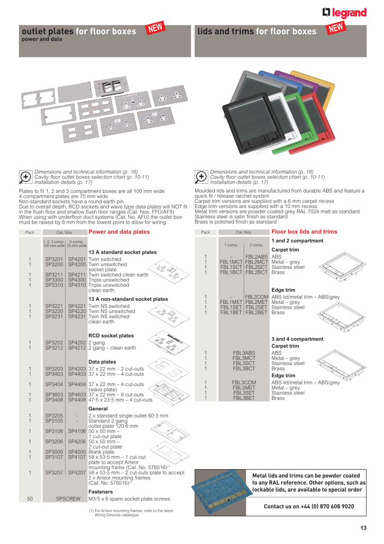
cavity floor service outlet boxes and grommetstechnical information
n Cavity floor service outlet boxes
Floor box basesCat. Nos. CAV1, CAV2, CAV3 and CAV4
n 250 mm grommet
Power grommet
n 150 mm plastic grommets
Access grommet
55
148
169Ø
Ø
102
148Ø169
Ø
13 A power grommet144
60
9540
144
60
9540
55
248
265
55
248
265
n 125 mm aluminium grommets
Access grommet
60
90
60
90
Cavity Box
22035
7540
270
265
3 Compartment
4 Compartment
303
87 87 87
65 65 65 65
LC
DB
229
3 compartment
4 compartment
100
75 75 75 75
W
100 100
Contractor floor boxCut-out 302-304 mm x 219-221 mm
302
8041
39
Steel Base Box
Carpet Trim Frame
Lid
A
Steel Base Box237
225
195
165
80 80 80
302
8350
33
Steel Base Box
Carpet Trim Frame
Lid
A
237
225
195
131
86 86 86
232 225
315
8546
35
A
237
225
195
132
87 87 87
246 232
302
8041
39
Steel Base Box
Carpet Trim Frame
Lid
A
Steel Base Box237
225
195
165
80 80 80
302
8350
33
Steel Base Box
Carpet Trim Frame
Lid
A
237
225
195
131
86 86 86
232 225
315
8546
35
A
237
225
195
132
87 87 87
246 232
Cat. No. LSG2
All dimensions (mm) are nominal
Cutout D B C W L Plate SizeCAV185 85 45 40 165 203 100CAV275 75 35 40 263 203 100CAV285 85 45 40 263 203 100CAV2110 110 45 65 263 203 100CAV375 75 35 40 340 203 100CAV385 85 45 40 340 203 100CAV3110 110 45 65 340 203 100CAV475 75 35 40 340 203 75CAV485 85 45 40 340 203 75CAV4110 110 45 65 340 203 75
Cat. No. SG6
Cat. No. PG6
Cat. No. 089307
Cat. No. AM1C
016_017_Floor_2012 v3.indd 16 21/09/2012 16:05
17
cavity floor service outlet boxes and grommetsinstallation
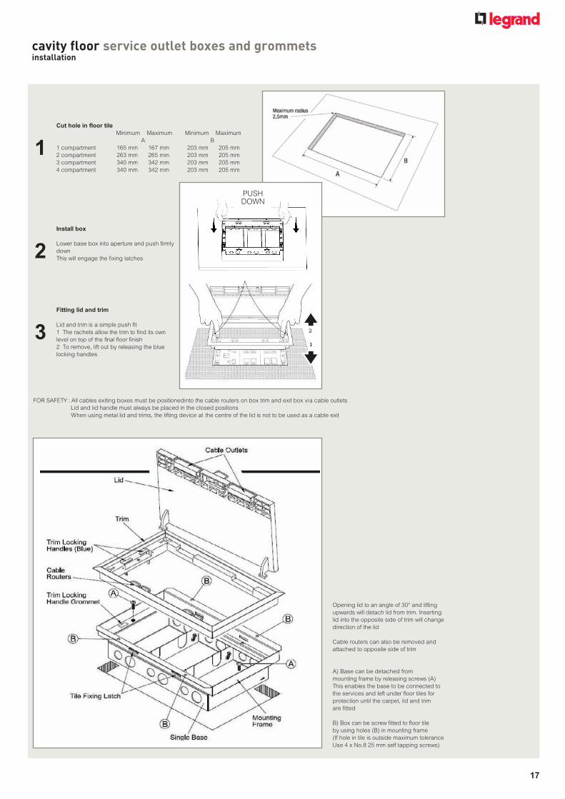
Cut hole in floor tileMinimum Maximum Minimum Maximum
1 compartment 165 mm 167 mm 203 mm 205 mm2 compartment 263 mm 265 mm 203 mm 205 mm3 compartment 340 mm 342 mm 203 mm 205 mm4 compartment 340 mm 342 mm 203 mm 205 mm
Install box
This will engage the fixing latches
Fitting lid and trim
Lid and trim is a simple push fit
B) Box can be screw fitted to floor tileby using holes (B) in mounting frame(If hole in tile is outside maximum toleranceUse 4 x No.8 25 mm self tapping screws)
FOR SAFETY : All cables exiting boxes must be positioned into the cable routers on box trim and exit box via cable outletsLid and lid handle must always be placed in the closed positionsWhen using metal lid and trims, the lifting device at the centre of the lid is not to be used as a cable exit
BA
1
2
3
Lower base box into aperture and push firmly down
1 The rachets allow the trim to find its own level on top of the final floor finish2 To remove, lift out by releasing the blue locking handles
A) Base can be detached frommounting frame by releasing screws (A)This enables the base to be connected tothe services and left under floor tiles forprotection until the carpet, lid and trimare fitted
Cable routers can also be removed andattached to opposite side of trim
Opening lid to an angle of 30° and liftingupwards will detach lid from trim. Insertinglid into the opposite side of trim will changedirection of the lid
PUSHDOWN
016_017_Floor_2012 v3.indd 17 21/09/2012 16:53

Power track... delivering power to the workspaceLegrand’s Arena-Walsall power track is the ultra compact, versatile choice to supply power in cavity floor scenarios. When used with a Soluflex cavity floor system it creates a flexible cable management system which can adapt to changing requirements.
This compact busbar system is available in standard, clean earth, dual circuit and three phase versions - all of which are quick to install and flexible:
• Push fit connections
• Easily reconfigured
• Overall height of just 47 mm
• ASTA certified and tested to BS EN 60439-1:1999 and BS EN 60439-2:2000
18
Feature Pages.indd 18 21/09/2012 17:58

Power track... delivering power to the workspace
STANDARDTwo bar and earth 63 A power track system
DUAL CIRCUITFive bar and earth 50 A power track system incorporating both standard and clean earth systems within one enclosure. Tap-offs from the standard, clean earth and dual circuit ranges can be used
CLEAN EARTHThree bar and earth 63 A power track system including an independent clean earth copper bar
THREE PHASEFour bar and earth 50 A power track system. Three phased bars, one neutral bar and earth
PRODUCT RANGES
19
The Arena-Walsall power track system has much to offer the specifi er, installer and end user:
Specifi er - The modular system simplifi es the wiring plan to a linear grid which is easy to design and has built in fl exibility to cope with a wide range of fi nal end user requirements which are often unknown at the design stage.
Installer - The principle of a linear grid simplifi es the estimating process. The system is quick and easy to install on site and its modular nature helps reduce wastage associated with trunking, tray and cable.
The end user - The availability of shuttered outlets throughout the linear grid facilitates the movement, addition and deletion of local power supplies. This facility is benefi cial, particularly in commercial environments which experience frequent change.
Feature Pages.indd 19 21/09/2012 17:58

20
Arena-Walsall® power track systemstandard
Two bar and earth 63 A power track system
Pack Cat. Nos. Tracklengthsandfeederunit
Standardtracklengths
Supplied complete with hold down clamps Recommended spacing between two clamps no greater than one metre
1 STL12 1·2 metres, 4 tap-offs 1 STL18 1·8 metres, 6 tap-offs 1 STL24 2·4 metres, 8 tap-offs 1 STL30 3·0 metres, 10 tap-offs 1 STL36 3·6 metres, 12 tap-offs
Standardfeederunit
Supplied with one end cap to be fitted to track end
1 SFU 2 x 20/25 mm knockout entries Terminal capacity 16 mm2 maximum
Standardtap-offs
All tap-offs conform to Section 607 of BS 7671 : 2001 Supplied with new cable colours to
BS 7671 : 2001 amendment No. 2 ‘fixed wiring’ These tap-offs can also be used with the dual circuit
power track
1 STO3U 3 metres, unfused 1 STO3F 3 metres, fused 1 STO5F 5 metres, fused
picto loupe-65765j.eps
Dimensions and technical information (p. 24-25)
2 Bar + Earth
Clean Earth
Single Phase
Extra Earth
Dual Circuit
Pack Cat. Nos. Flexiblebendsandteeunits
Standardflexiblebend
1 SFB1 Comprises a length of 25 mm conduit with a plug-in feed at each end, pre-wired with 10 mm2 tri-rated cable
Cable length = 1 metre Other lengths are available to special order Can be used as a bend or an offset
Standardteeunits
Supplied with slider and one end cap
1 STU A Left feed 1 STU B Centre feed 1 STU C Right feed
Standardfourway
1 SFW Supplied complete with slider and two end caps
Accessories
1 SHC Spareholddownclamp
Hangerbrackets
1 SVB Vertical hanger bracket 1 SHB Horizontal hanger bracket
1 SEC Spareendcap
128
80
Standardpowertrackisdenotedbyawhitelabelwithablackflash
Standard feeder unit
SFU
Standard track length
STL12
Standard flexible bend
SFB 1
Standard tap-off
STO3U
020_Floor_2012 v2.indd 20 21/09/2012 09:55
21
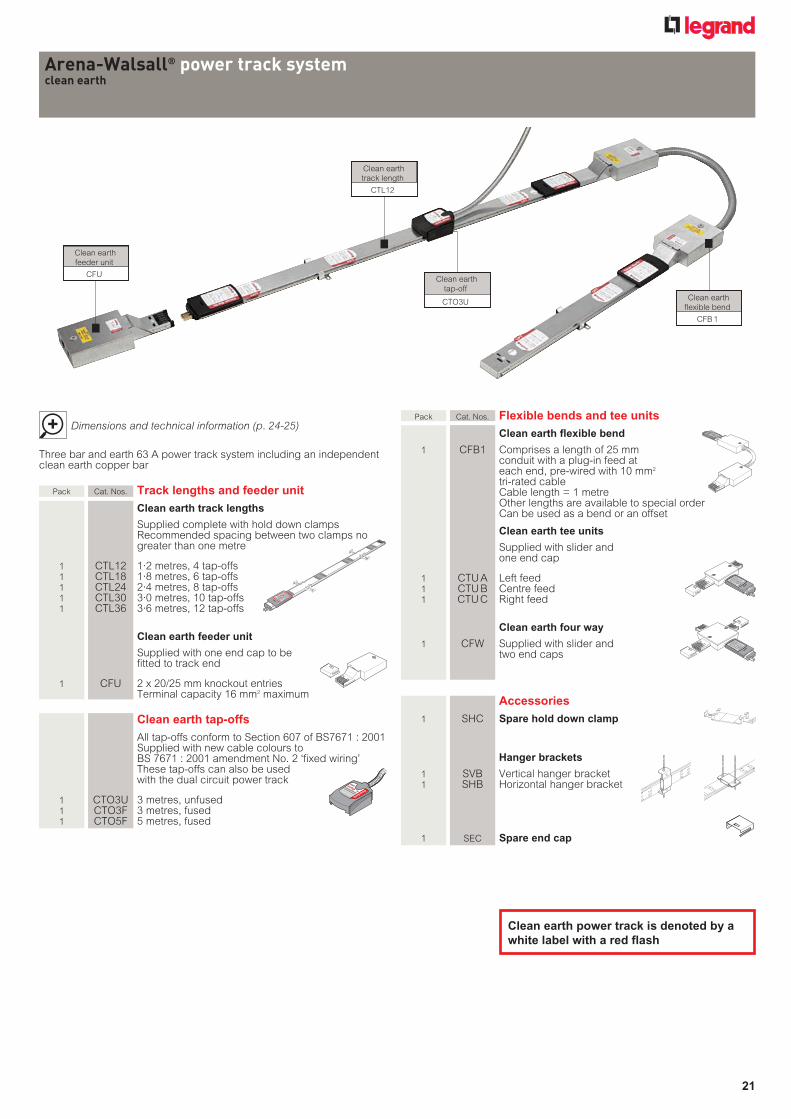
Arena-Walsall® power track systemclean earth
Three bar and earth 63 A power track system including an independent clean earth copper bar
Pack Cat. Nos. Tracklengthsandfeederunit
Cleanearthtracklengths
Supplied complete with hold down clamps Recommended spacing between two clamps no greater than one metre
1 CTL12 1·2 metres, 4 tap-offs 1 CTL18 1·8 metres, 6 tap-offs 1 CTL24 2·4 metres, 8 tap-offs 1 CTL30 3·0 metres, 10 tap-offs 1 CTL36 3·6 metres, 12 tap-offs
Cleanearthfeederunit
Supplied with one end cap to be fitted to track end
1 CFU 2 x 20/25 mm knockout entries Terminal capacity 16 mm2 maximum
Cleanearthtap-offs
All tap-offs conform to Section 607 of BS7671 : 2001 Supplied with new cable colours to
BS 7671 : 2001 amendment No. 2 ‘fixed wiring’ These tap-offs can also be used
with the dual circuit power track
1 CTO3U 3 metres, unfused 1 CTO3F 3 metres, fused 1 CTO5F 5 metres, fused
picto loupe-65765j.eps
Dimensions and technical information (p. 24-25)
2 Bar + Earth
Clean Earth
Single Phase
Extra Earth
Dual Circuit
Pack Cat. Nos. Flexiblebendsandteeunits
Cleanearthflexiblebend
1 CFB1 Comprises a length of 25 mm conduit with a plug-in feed at each end, pre-wired with 10 mm2
tri-rated cable Cable length = 1 metre Other lengths are available to special order Can be used as a bend or an offset
Cleanearthteeunits
Supplied with slider and one end cap
1 CTU A Left feed 1 CTU B Centre feed 1 CTU C Right feed
Cleanearthfourway
1 CFW Supplied with slider and two end caps
Accessories
1 SHC Spareholddownclamp
Hangerbrackets
1 SVB Vertical hanger bracket 1 SHB Horizontal hanger bracket
1 SEC Spareendcap
Cleanearthpowertrackisdenotedbyawhitelabelwitharedflash
Clean earth feeder unit
CFU
Clean earth track length
CTL12
Clean earth flexible bend
CFB 1
Clean earth tap-off
CTO3U
021_Floor_2012 v1.indd 21 21/09/2012 09:56

22
Arena-Walsall® power track systemdual circuit
Five bar and earth 50 A power track system incorporating both standard and clean earth systems within one enclosure
Pack Cat. Nos. Tracklengthsandfeederunit
Dualcircuittracklengths
Supplied complete with hold down clamps Recommended spacing between two clamps no greater than one metre
1 DTL12 1·2 metres, 4 tap-offs 1 DTL18 1·8 metres, 6 tap-offs 1 DTL24 2·4 metres, 8 tap-offs 1 DTL30 3·0 metres, 10 tap-offs 1 DTL36 3·6 metres, 12 tap-offs
Dualcircuitfeederunit
Supplied with one end cap to be fitted to track end
1 DFU 2 x 20/25 mm knockout entries Terminal capacity 16 mm2 maximum
Dualcircuittap-offs
All tap-offs conform to Section 607 of BS 7671 : 2001 Supplied with new cable colours to
BS 7671 : 2001 amendment No. 2 ‘fixed wiring’ These tap-offs must only be used
with the dual circuit power track All tap-offs from standard and
clean earth track can also be used
1 DTO3U 3 metres, unfused 1 DTO3F 3 metres, fused 1 DTO5F 5 metres, fused
picto loupe-65765j.eps
Dimensions and technical information (p. 24-25)
Pack Cat. Nos. Flexiblebendsandteeunits
Dualcircuitflexiblebend
1 DFB1 Comprises a length of 25 mm conduit with a plug-in feed at each end, pre-wired with 10 mm2 tri-rated cable
Cable length = 1 metre Other lengths are available to special order Can be used as a bend or an offset
Dualcircuitteeunits
Supplied with slider and one end cap
1 DTU A Left feed 1 DTU B Centre feed 1 DTU C Right feed
Dualcircuitfourway
1 DFW Supplied with slider and two end caps
Accessories
1 SHC Spareholddownclamp
Hangerbrackets
1 SVB Vertical hanger bracket 1 SHB Horizontal hanger bracket
1 SEC Spareendcap
2 Bar + Earth
Clean Earth
Single Phase
Extra Earth
Dual Circuit
For pre-wired floor boxes and grommets, see p. 15
Contact us on +44 (0) 870 608 9020
Dualcircuitpowertrackisdenotedbyawhitelabelwithablackandredflash
Dual circuit flexible bend
DFB 1
Dual circuit tap-off
DTO3U
Dual circuit feeder unit
DFU
Dual circuit track length
DTL12
022_Floor_2012 v1.indd 22 21/09/2012 10:02

23
Arena-Walsall® power track systemthree phase
Four bar and earth 50 A power track system Three phased bars, one neutral bar and earth
Pack Cat. Nos. Tracklengthsandfeederunit
Threephasetracklengths
Supplied complete with hold down clamps Recommended spacing between two clamps no greater than one metre
1 PTL12 1·2 metres, 4 tap-offs 1 PTL18 1·8 metres, 6 tap-offs 1 PTL24 2·4 metres, 8 tap-offs 1 PTL30 3·0 metres, 10 tap-offs 1 PTL36 3·6 metres, 12 tap-offs
Threephasefeederunit
Supplied with one end cap to be fitted to track end
1 PFU 2 x 20/25mm knockout entries Terminal capacity 16 mm2 maximum
Tap-offsforthreephasepowertrack
Singlephasetap-offs
All tap-offs conform to Section 607 of BS 7671 : 2001 Supplied with new cable colours to
BS 7671 : 2001 amendment No. 2 ‘fixed wiring’ These tap-offs must only be used
with the 3 phase power track
1 PTO3UR 3 metres, unfused reconfigurable 1 PTO3FR 3 metres, fused reconfigurable 1 PTO5FR 5 metres, fused reconfigurable
Threephasetap-off
All tap-offs conform to Section 607 of BS7671 : 2001 Supplied with new cable colours to
BS 7671 : 2001 amendment No. 2 ‘fixed wiring’ This tap-off must only be used
with the 3 phase power track
1 PTO3U 3 metres, unfused (L1, L2 and L3 connected)
picto loupe-65765j.eps
Dimensions and technical information (p. 24-25)
Pack Cat. Nos. Flexiblebendsandteeunits
Threephaseflexiblebend
1 PFB1 Comprises a length of 25 mm conduit with a plug-in feed at each end, pre-wired with 10 mm2 tri-rated cable
Cable length = 1 metre Other lengths are available to special order Can be used as a bend or an offset
Threephaseteeunits
Supplied with slider and one end cap
1 PTU A Left feed 1 PTU B Centre feed 1 PTU C Right feed
Threephasefourway
1 PFW Supplied with slider and two end caps
Accessories
1 SHC Spareholddownclamp
Hangerbrackets
1 SVB Vertical hanger bracket 1 SHB Horizontal hanger bracket
1 SEC Spareendcap
2 Bar + Earth
Clean Earth
Single Phase
Extra Earth
Dual Circuit
2 Bar + Earth
Clean Earth
Single Phase
Extra Earth
Dual Circuit
For pre-wired floor boxes and grommets, see p. 15
Contact us on +44 (0) 870 608 9020
Threephasepowertrackisdenotedbyawhitelabelwithablueflash
Single phase feeder unit
PFU
Single phase track length
PTL12
Three phase flexible bend
PFB 1
Single phase tap-off
PTO3UR
023_Floor_2012 v1.indd 23 21/09/2012 10:04

24
Arena-Walsall® power track systemtechnical information
n Terminal block connections
Standard Clean earth Dual circuit
Three phase
TT T
T
N L N L
N
N2 L2 N1 L1
L2L3 L1
The three phase system is not interchangeable
The three types above are compatible and an installation can be downrated from the dual circuit to either standard or clean earth in mid-run by means of a flexible bend or direct connection (see opposite)
n Specification / technical data
Electrical data Rated current 63 A/50 A Rated voltage 250 V/415 V Frequency 50/60 Hz Rated short circuit withstand 16 kA Track conductor resistance – line and neutral 3 mΩ/m Track conductor impedance 1·43 mΩ/m
Volt drops Line and neutral : track 2·86 mV/A/m Tap-off (32 A - 4 mm2 cable) 10 mV/A/m Flexible bend (10 mm2 tri-rated cable) 3·7 mV/A/m Feed unit 0·3 mV/A/m Track connector 0·4 mV/A/m
Earth fault loop Impedance : L+N track conductors 1·5 mΩ/m Earth track conductor 1·2 mΩ/m Tap-off (32 A - 4 mm2 cable) 33 mΩ (3 metre L/N/E) Feed unit 0·3 mΩ Track connector 0·4 mΩ Flexible bend (10 mm2 tri-rated cable) 3·7 mΩ (1 metre L/N/E)
Mechanical data Number of conductors PE + 2,3,4 and 5 Track conductor cross section area 13 mm2
Incoming cable termination capacity 16 mm2
Tap-off cable 32 A unfused 4 mm2
Tap-off cable 13 A fused L/N : 2·5 mm2, E : 4 mm2
Tap-off conduit 16 mm/20 mm diameter Feeder conduit entry 20 mm/25 mm diameter IP rating IP 40 (when fully assembled) Maximum profile height 47 mm including tap-off Track height 17 mm
Material specification Track housing Galvanised steel Track conductors High conductivity copper Track insulator Self extinguishing PVC extrusion Sockets, track connectors, track ends Nylon Tap-off plugs Nylon End shutters and track shutters Glass filled nylon Tap-off / flexible bend cable LSF/PVC Tap-off / feeder and connector pins Brass
n Track length
60
75
17
47
60
75
17
47WITHTAP-OFF
Simply push-fit 3end cap on tounused ends of track lengths.
LENGTH
Track Length End Cap
19
6063
60
75
17
47All dimensions in mm
Overall height : 47 mm with feeder unit and tap-off
All dimensions (mm) are nominal
CertificationAsta Certified and tested to BS EN 60439-1 : 1999 and BS EN 60439-2 : 2000Manufactured within an approved ISO 9001 : 2008 facility
IEE Wiring RegulationsLegrand power track system is suitable for installation to BS7671 : 2001 or BS 7671 : 2008
Installations having high protective conductor currents (formerly Section 607, BS7671 : 2001)
Legrand power track system allows compliance with regulation 543·7, BS7671 : 2008 and Section 607, BS7671 : 2001. However, this requirement must be stated at the time of order to ensure the correct system components are selected
n Standards
024_025_Floor_2012 v3.indd 24 21/09/2012 10:08

25
n Flexible bends
n Tees and four ways
n End cap
19
6063
19
6063
crop
crop
crop
crop
crop
crop
crop
crop
crop
crop
crop
crop
1 metre
1 metre
Supplied complete with slider, lid, turnbuckle fasteners and end cap(s)
Cat. No. SEC
Left feed tee unitComponent Cat. No./A
Centre feed tee unitComponent Cat. No./B
Right feed tee unitComponent Cat. No./C
n Hold down clamp
Each power track length is supplied already fitted with sliding clamps• 2 clamps on each 1·2, 1·8 and 2·4
metre length• 3 clamps on each 3·0 and 3·6
metre length
n Vertical hanger bracket
Supplied in two parts complete with clamping screws (A)Use one M8 threaded rod (B) and four M8 nuts (C) (one above and below each bracket flange)Recommended spacing between vertical hanger brackets is 1 metre maximum
A
C
B
A
C
A
C
B
A
C
n Horizontal hanger bracket
Supplied in two partsUse two M8 threaded rods (A) and four M8 nuts (B) (one above and below each bracket flange)Recommended spacing between horizontal hanger brackets is 1 metre maximum
B
A
B
A
B
A
B
A
128
80
128
80
n Feeder units
n Tap-offs and pre-wired floor boxes
283
47
125
60
283
47
125
60
Two – 20/25 mm knockout entriesTerminal capacity 16 mm2 maximumSupplied complete with terminal block, lid and turnbuckle fastener and one end cap
Unfused tap-offs are rated at 32 AFused tap-offs are supplied with a standard BS 1362 13 A fuse
Tap-off length refers to the cable and not the conduit lengthThe conduit is 250 mm shorter than the cable length
Cable Length - 3 or 5 metres
43
Cable length - 3 or 5 m
43 mm
Section 434.2.1 of the Wiring Regulations requires any conductor exceeding 3 m in length to have a fault current protective device (e.g. fuse) at the point where current carrying capacity is reduced (tap-off plug)All tap-offs over 3 m will be supplied with a BS 1362 13 A fuse fitted within the plugIf the system is to be protected by a 32 A breaker then unfused tap-offs exceeding 3 m may be specified at time of order If a floor service unit, supplied by a single tap-off, contains more than 2 x 13 A socket outlets then the total loading of the service box must not exceed 32 ampsOther pre-wired tap-off lengths are available on request, contact us on +44 (0) 870 608 9020
n Tap-offs for three phase power track
PTO3FR / PTO5FR(fused)
PTO3U(unfused)
PTO3UR(unfused)
Single phase tap-offs Three phase tap-off
All dimensions (mm) are nominal
024_025_Floor_2012 v3.indd 25 21/09/2012 17:13

Solufl ex®... innovation in cable management fl ooringSolufl ex is much more than just a raised fl oor, it’s a quick and simple to install cable management solution. This innovative system integrates low-level fl ooring with Legrand’s market leading cable management solutions, allowing cables for power, data and communication to be structured in a logical, ready to use layout that remains hidden to end users.
26
Feature Pages.indd 26 21/09/2012 18:16
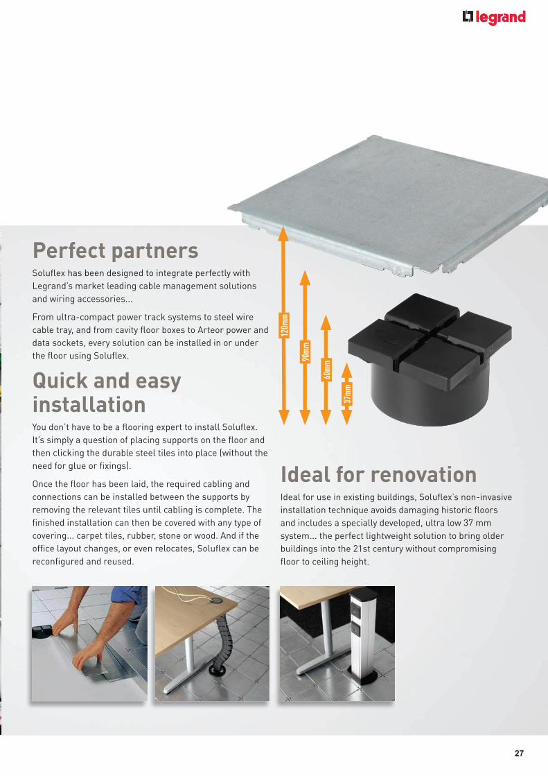
Perfect partnersSolufl ex has been designed to integrate perfectly with Legrand’s market leading cable management solutions and wiring accessories...
From ultra-compact power track systems to steel wire cable tray, and from cavity fl oor boxes to Arteor power and data sockets, every solution can be installed in or under the fl oor using Solufl ex.
Quick and easy installationYou don’t have to be a fl ooring expert to install Solufl ex. It’s simply a question of placing supports on the fl oor and then clicking the durable steel tiles into place (without the need for glue or fi xings).
Once the fl oor has been laid, the required cabling and connections can be installed between the supports by removing the relevant tiles until cabling is complete. The fi nished installation can then be covered with any type of covering... carpet tiles, rubber, stone or wood. And if the offi ce layout changes, or even relocates, Solufl ex can be reconfi gured and reused.
Ideal for renovationIdeal for use in existing buildings, Solufl ex’s non-invasive installation technique avoids damaging historic fl oors and includes a specially developed, ultra low 37 mm system... the perfect lightweight solution to bring older buildings into the 21st century without compromising fl oor to ceiling height.
120m
m
90m
m
60m
m
37m
m
27
Feature Pages.indd 27 21/09/2012 17:52

28
Height(mm)
Floor box tile Floor box lid + trim
3 comp. twin socket
module
4 comp. twin socket
module
3 comp. blank
module
4 comp. blank
module
3 comp. data module
4 comp. data module
Cable snake – grey(1)
Cable snake – black(1)
Power pole(2)
37 - - - - - - - - 81906 40 81906 41 86502 10
60 84090 81 8218 21 8218 22 8218 23 8218 24 8218 25 8218 26 8218 27 81906 40 81906 41 86502 10
90 84090 81 8218 21 8218 22 8218 23 8218 24 8218 25 8218 26 8218 27 81906 40 81906 41 86502 10
120 84090 81 8218 21 8218 22 8218 23 8218 24 8218 25 8218 26 8218 27 81906 40 81906 41 86502 10
Soluflex® cavity floor systemselection chart
Height(mm)
Tile Support Double edge plate
Single edge plate
Step Step corner Ramp Earthing tile Cable outlet tile
Chrome outlet grommet
Accessory outlet tile
Fixing bracket Semi-submerged power unit 2 x 240 V
(empty)
Semi-submerged data unit 2 x 2 data
(empty)
Fully submerged power unit 2 x 240 V
(empty)
Fully submerged data unit
2 x 2 data (empty)
37 84000 10 84037 00 84000 60 84000 61 84037 22 84037 30 84037 40 84000 20 84000 30 81902 32 84000 40 84000 50 84037 50 84037 51 - -
60 84000 10 84060 00 84000 60 84000 61 84060 22 84060 30 84060 40 84000 20 84000 30 81902 32 84000 40 84000 50 - - 84060 72 84060 73
90 84000 10 84090 00 84000 60 84000 61 84090 22 84090 30 84090 40 84000 20 84000 30 81902 32 84000 40 84000 50 - - - -
120 84000 10 84120 00 84000 60 84000 61 84120 22 84120 30 84120 40 84000 20 84000 30 81902 32 84000 40 84000 50 - - - -
n Floor boxes with lid and trim assemblies :Suitable for 60, 90 and 120 mm systems Specials also available, including RCD and RCBO options to
comply with 17th Edition requirements
(1) For use with accessory outlet tile or cable outlet tile(2) For use with accessory outlet tile. Standard version shown. Requires back box, Cat. No. 8218 30. Other configurations available to special order.
Contact us on +44 (0) 870 608 9020
028_029_Floor_2012 v4.indd 28 21/09/2012 10:12
29
Height(mm)
Floor box tile Floor box lid + trim
3 comp. twin socket
module
4 comp. twin socket
module
3 comp. blank
module
4 comp. blank
module
3 comp. data module
4 comp. data module
Cable snake – grey(1)
Cable snake – black(1)
Power pole(2)
37 - - - - - - - - 81906 40 81906 41 86502 10
60 84090 81 8218 21 8218 22 8218 23 8218 24 8218 25 8218 26 8218 27 81906 40 81906 41 86502 10
90 84090 81 8218 21 8218 22 8218 23 8218 24 8218 25 8218 26 8218 27 81906 40 81906 41 86502 10
120 84090 81 8218 21 8218 22 8218 23 8218 24 8218 25 8218 26 8218 27 81906 40 81906 41 86502 10
Soluflex® cavity floor systemselection chart
Height(mm)
Tile Support Double edge plate
Single edge plate
Step Step corner Ramp Earthing tile Cable outlet tile
Chrome outlet grommet
Accessory outlet tile
Fixing bracket Semi-submerged power unit 2 x 240 V
(empty)
Semi-submerged data unit 2 x 2 data
(empty)
Fully submerged power unit 2 x 240 V
(empty)
Fully submerged data unit 2 x 2 data
(empty)
37 84000 10 84037 00 84000 60 84000 61 84037 22 84037 30 84037 40 84000 20 84000 30 81902 32 84000 40 84000 50 84037 50 84037 51 - -
60 84000 10 84060 00 84000 60 84000 61 84060 22 84060 30 84060 40 84000 20 84000 30 81902 32 84000 40 84000 50 - - 84060 72 84060 73
90 84000 10 84090 00 84000 60 84000 61 84090 22 84090 30 84090 40 84000 20 84000 30 81902 32 84000 40 84000 50 - - - -
120 84000 10 84120 00 84000 60 84000 61 84120 22 84120 30 84120 40 84000 20 84000 30 81902 32 84000 40 84000 50 - - - -
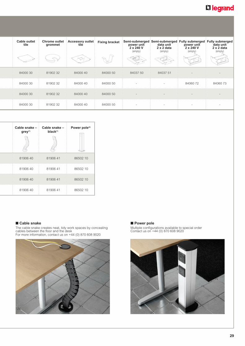
n Cable snakeThe cable snake creates neat, tidy work spaces by concealing cables between the floor and the deskFor more information, contact us on +44 (0) 870 608 9020
n Power poleMultiple configurations available to special order Contact us on +44 (0) 870 608 9020
028_029_Floor_2012 v4.indd 29 21/09/2012 16:35

30
Soluflex®
ultra low cavity floor system
Pack Cat.Nos. Floorcomponents(continued)
Stepcorner
Width900mm Height (mm) 1 8403730 37 1 8406030 60 1 8409030 90 1 8412030 120
Ramp
10%incline Height Length Width (mm) (mm) (mm) 1 8403740 37 400 112 1 8406040 60 616 112 1 8409040 90 898 112 1 8412040 120 1181 112
Cablemanagementfloorsystem225x225mmtilesmanufacturedfrompre-galavanisedsteelwith13mmreturnIntegratedearthingdesignClickfit,nofixingsrequiredSupportmanufacturedfromrecycledpolypropylene
Pack Cat.Nos. Floorcomponents
Tile
1 8400010 225x225mmfloortile
Floorsupports
1 8403700 37mmheight(35mmsupport–37mminc.tile)
1 8406000 60mmheight(58mmsupport–60mminc.tile)
1 8409000 90mmheight(88mmsupport–90mminc.tile)
1 8412000 120mmheight(118mmsupport–120mminc.tile)
Earthingtile
1 8400020 225x225mmEarthingclamp6mm2(max.)1earthingtileper100mm2
Edgeplates
UsedtofinishinstallationagainstwallTrimtosizeonsite
1 8400060 900x300mmdoubleedgeplate 1 8400061 900x300mmsingleedgeplate
Step
Width900mm Height (mm) 1 8403722 37 1 8406022 60 1 8409022 90 1 8412022 120
Selection chart (p. 28-29) Installation instructions (p. 33)Dimensions (p. 34-35)
Floorboxtile
8409081Ramp
8406040
Support
8406000
Cableoutlettile
8400030
Accessoryoutlettile
8400040
Stepcorner
8406030
Step
8406022
030_031_Floor_2012 v8.indd 30 21/09/2012 10:17

31
Soluflex®
ultra low cavity floor system (continued)
Pack Cat.Nos. Universaloutlets
Accessoryoutlettile
1 8400040 225x225mm Usedtofixpowerpoles,
cablesnakeorgrommets
Aluminiumpowerpole
1 8650210 670mmhigh 1 821830 Singlepowerpolebackbox
1 8400050 Accessoryoutlettilefixingbracket
Accessories
1 8190232 Chromeoutletgrommet
1 8190640 Greycablesnake
1 8190641 Blackcablesnake
1 8400030 Cableoutlettile
Cablemanagementfloorsystem225x225mmtilesmanufacturedfrompre-galavanisedsteelwith13mmreturnIntegratedearthingdesignClickfit,nofixingsrequiredSupportmanufacturedfromrecycledpolypropylene
Pack Cat.Nos. Floorboxfor60,90and120mmhighsystemsonly
Floorbox
1 8409081 450x450mmfloorboxtile
1 821821 Floorboxlidandtrim
Outletplateoptions
1 821822 3compartmenttwinswitchedsocketmodule
1 821824 3compartmentblankmodule 1 821826 3compartmentdatamodule
(4x37x22mmcut-outs) 1 821823 4compartmenttwinswitched
socketmodule 1 821825 4compartmentblankmodule 1 821827 4compartmentdatamodule
(4x37x22mmcut-outs)
Outletsolutionsfor37mmhighsystems
Semi-submerged
1 8403750 37mmpoweroutlettoaccept2xArteordoublemodules(1)
1 8403751 37mmdataoutlettoaccept2xArteordoublemodules(1)
Outletsolutionsfor60mmhighsystems
Fullysubmerged
1 8406072 60mmpoweroutlettoaccept2xArteordoublemodules(1)
1 8406073 60mmdataoutlettoaccept2xArteordoublemodules(1)
Selection chart (p. 28-29) Installation instructions (p. 33)Dimensions (p. 34-35)
Floorboxtile
8409081Ramp
8406040
Support
8406000
Cableoutlettile
8400030
Accessoryoutlettile
8400040
Stepcorner
8406030
Step
8406022
(1)ForArteormodules,refertothelatestWiringDevicescatalogue
030_031_Floor_2012v8.indd31 21/09/201216:36
32
Soluflex® cavity floor systemtechnical information
n Specification / technical data
ConstructionThe Soluflex cable floor system is constructed of a raised floor of tiles and supports with integrated cabling and connection points for telecoms, power and data
Materials • The tiles are manufactured from pre-galvanised sheet steel in
accordance with BS EN 10326• The supports are made of polypropylene. Inflammability class B2
according to DIN 4102
Weights and measures• Dimensions of tiles : 225 x 225 mm • 4 different heights : 37 mm, 60 mm, 90 mm, 120 mm
Other heights available on request• Weight of the Soluflex cable floor system : approx. 20 kg per m2
n Load bearing data• Point load per tile/support : 1 500 Newton/25 mm2
• Equal divided load of 3 000 kg per m2
• Minimum safety factor : V = 1·71
n Sound measurementsThe sound measurements have been carried out in the laboratory of consultancy firm Peutz & Associes. The complete report can be obtained from our sales department
Acoustic • Flanking airborne sound insulation in accordance with
ISO 717-1 : 1996 Tested according to ISO 140-12 : 2000 Soluflex cable floor system + carpet tiles, without mineral wool underneath the partition wall : Dn,f,w = 48 dB Soluflex cable floor system + carpet tiles, with mineral wool underneath the partition wall : Dn,f,w = 48 dB
• Flanking impact sound insulation in accordance with ISO 717-2 : 1996 Tested in accordance to ISO 140-12 : 2000Soluflex cable floor system + carpet tiles, without mineral wool underneath the partition wall : Ln,f,w = 49 dB Soluflex cable floor system + carpet tiles, with mineral wool underneath the partition wall : Ln,f,w = 39 dB
• Vertical impact sound insulation improvement in accordance with ISO 717-2 : 1996Tested in accordance with ISO 140-8 : 1978 Concrete floor 140 mm + Soluflex rLw = 17 dB rllin = 7 dBConcrete floor 140 mm + Soluflex + carpet tiles rLw = 24 dB rllin = 12 dB
Tested to : PSA MOB PF2PS/SPU
BS EN 12825 : 2001
Working load : 1·9kN
n Safety
• Safety against short circuits : Soluflex is earthed (as long as 1 earthing tile is installed per 100 m2)
• Fire resistance : due to its low plenum height Soluflex is self-extinguishing Tested according to BS EN 13501-1, class B(fl)S1-d0
Other characteristicsThe Soluflex cable floor system feels extremely solid. Since the system is not adjustable in height, it needs no later adjustmentThe grid layout of the system means the cables are perfectly parallel, and you can cross data cables at the required angle of 90°
n TNO-fireFire propagationIts low plenum height enables the cable floor system to be self-extinguishing NEN-EN 13501-1 B(fl) S1-d0 NEN 1775 : A – Inflammability – complies with the class
T1 criteria for inflammabilityB – Horizontal fire propagation : all heights
maximum horizontal fire propagation = 0 cm, which implies a critical density of heat flow of more than 11 kW/m2
Classification according to NEN 1775 : Class T1
NEN 6066 :With (highest) heat flow supply of 50 kW/m2 :(highest) normative smoke density smaller than 0·5 m-1, which is very little smoke production in case of fire
DIN 4102 :
Resistance to fire in accordance with DIN 4102 Class B1
n Level floorThe sub-floor must be dry, clean and level, suitable for laying carpet. If the floor is not level, it must be levelled before you start to install the Soluflex cable floor system. Please contact your floor specialist for professional advic e
n KEMA-certificateSoluflex cable floor system has been certified by KEMA and meets the requirements for mechanical and electrical safety Earthing The cable floor system is automatically earthed, provided that 1 earthing tile is installed per 100 m2. Install an earthing tile every 14 m length in gangways
Ultimate Deflection Safety Class of load above under factor tolerance in 12kN working manufacture load
1 A 3 1
Ultimate Deflection Safety Class of load above under factor tolerance in 12kN working manufacture load
1 B 2 1
Working load : 2·9kN
032_Floor_2012 v1.indd 32 21/09/2012 10:21
33
Soluflex® cavity floor systemgeneral installation instructions
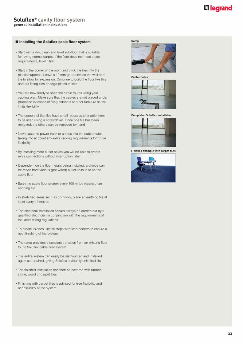
n Installing the Soluflex cable floor system
• Start with a dry, clean and level sub-floor that is suitable for laying normal carpet. If the floor does not meet these requirements, level it first
• Start in the corner of the room and click the tiles into the plastic supports. Leave a 10 mm gap between the wall and tile to allow for expansion. Continue to build the floor like this and cut fitting tiles or edge plates to size
• You are now ready to open the cable routes using your cabling plan. Make sure that the cables are not placed under proposed locations of filing cabinets or other furniture as this limits flexibility
• The corners of the tiles have small recesses to enable them to be lifted using a screwdriver. Once one tile has been removed, the others can be removed by hand
• Now place the power track or cables into the cable routes, taking into account any extra cabling requirements for future flexibility
• By installing more outlet boxes you will be able to create extra connections without interruption later
• Dependent on the floor height being installed, a choice can be made from various (pre-wired) outlet units in or on the cable floor
• Earth the cable floor system every 100 m2 by means of an earthing tile
• In stretched areas such as corridors, place an earthing tile at least every 14 metres
• The electrical installation should always be carried out by a qualified electrician in conjunction with the requirements of the latest wiring regulations
• To create ‘islands’, install steps with step corners to ensure a neat finishing of the system
• The ramp provides a constant transition from an existing floor to the Soluflex cable floor system
• The entire system can easily be dismounted and installed again as required, giving Soluflex a virtually unlimited life
• The finished installation can then be covered with rubber, stone, wood or carpet tiles
• Finishing with carpet tiles is advised for true flexibility and accessibility of the system
Ramp
Cable routes
Completed Soluflex installation
Finished example with carpet tiles
033_Floor_2012.indd 33 21/09/2012 10:22

34
Soluflex® cavity floor system dimensions37 mm, 60 mm, 90 mm, 120 mm height
Tile
Step corner
Steps
Single edge plate
Double edge plate
Supports
n Dimensions (mm)
All dimensions (mm) are nominal
For 37 mm height For 60 mm height
For 90 mm height For 120 mm height
For 37 mm height For 60 mm height
For 90 mm height For 120 mm height
Cat. No. 8400010
Cat. No. 8403700 Cat. No. 8406000
Cat. No. 8409000 Cat. No. 8412000
Cat. No. 8400060
Cat. No. 8400061
Cat. No. 8403722 Cat. No. 8406022
Cat. No. 8409022 Cat. No. 8412022
For 37 mm height
Cat. No. 8403730
For 60 mm height
Cat. No. 8406030
For 90 mm height
Cat. No. 8409030
For 120 mm height
Cat. No. 841203013
1313
1311
211
211
211
237
6090
120
1181
898
616
400
RampFor 37 mm height
Cat. No. 8403740
1313
1313
112
112
112
112
3760
9012
0
1181
898
616
400
For 60 mm height
Cat. No. 8406040
1313
1313
112
112
112
112
3760
9012
0
1181
898
616
400
For 90 mm height
Cat. No. 8409040
1313
1313
112
112
112
112
3760
9012
0
1181
898
616
400
For 120 mm height
Cat. No. 8412040
034_035_Floor_2012 v3.indd 34 21/09/2012 10:24

35
Soluflex® cavity floor system dimensions37 mm, 60 mm, 90 mm, 120 mm height (continued)
Dimensions (mm)
Earthing tile
Cat. No. 8400020
Cable outlet tile
Cat. No. 8400030
Chrome outlet grommet
Cat. No. 8190232
Accessory outlet tile
Cat. No. 8400040
Fixing bracket
Cat. No. 8400050
Fully submerged power unit 2 x 240 V (empty)For 60 mm range only
Cat. No. 8406072
Semi-submerged unitFor 37 mm range only
Cat. Nos. 8403750 Power 8403751 Data
Fully submerged data unit 2 x 2 data (empty)
For 60 mm range only
Cat. No. 8406073
For 60 mm, 90 mm, 120 mm ranges onlyFloor box tile
Cat. No. 8409081
All dimensions (mm) are nominal
034_035_Floor_2012 v3.indd 35 21/09/2012 10:24
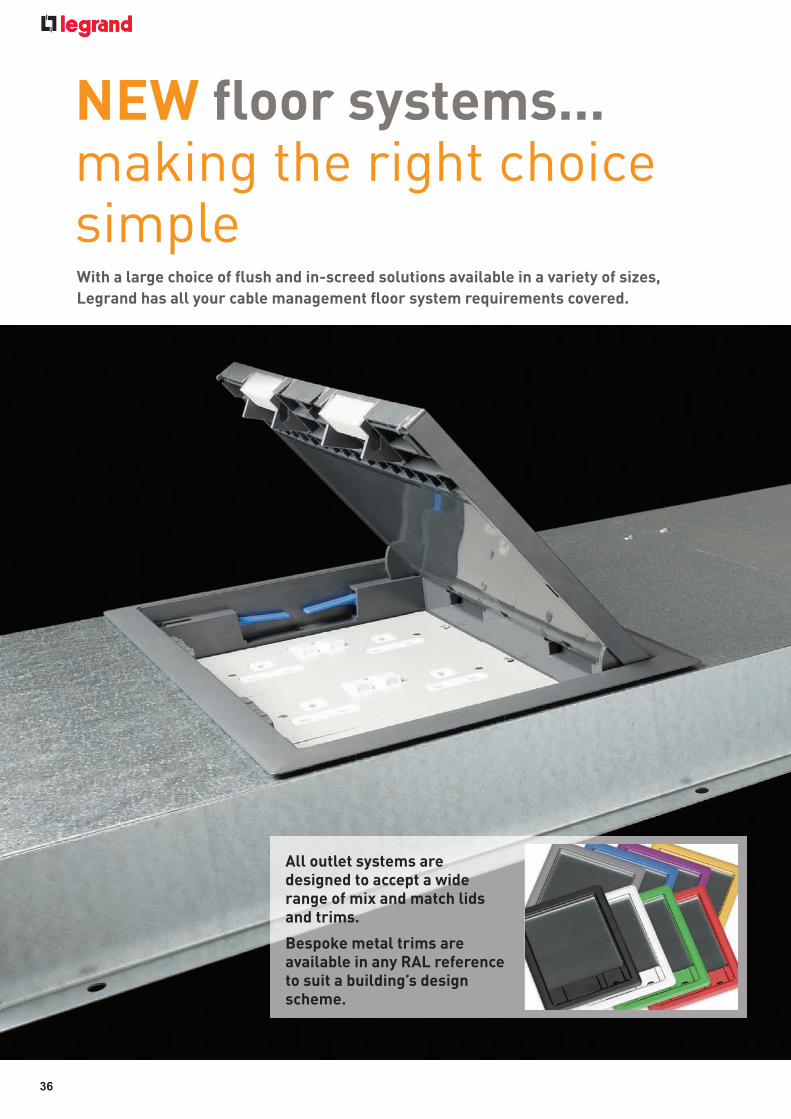
NEW fl oor systems... making the right choice simpleWith a large choice of fl ush and in-screed solutions available in a variety of sizes, Legrand has all your cable management fl oor system requirements covered.
All outlet systems are designed to accept a wide range of mix and match lids and trims.
Bespoke metal trims are available in any RAL reference to suit a building’s design scheme.
36
036_037_Floor_2012.indd 36 21/09/2012 18:45

NEW fl oor systems... making the right choice simple
FLUSH FLOOR TRUNKING• Commercial fl oor trunking system• Ideal for distributing power, data and
communication in any commercial environment
• Can be used if service outlets are required
• Cables can be accessed after installation has been completed
• Floor boxes can be positioned at any point along the trunking and removed and repositioned at a later date
FLUSH LID FLOOR TRUNKING • Commercial fl oor trunking system • Floor fi nish is fi tted over the fl ush lid
giving a neat fi nish • Available in a wide range of sizes • Suitable for long runs of cable where no
outlets are required
SHALLOW FLUSH FLOOR TRUNKING• Commercial fl oor trunking system• Designed to distribute power, data and
communication where the amount of screed that can be removed is limited
• Can be used if service outlets are required
• Cables can be accessed after installation has been completed
RECESSED LID FLOOR TRUNKING• Commercial fl oor trunking system• Floor fi nish is fi tted recessed into the
trunking lid• Suitable for use in environments where
access to cables may be required at a later date, for example hospitals
UNDERFLOOR DUCT • Commercial fl oor ducting system • Ducting is installed under the screed
providing a strong yet cost effective solution
• Positions of service outlet and junction boxes are fi xed prior to installation
• Service outlet and junction boxes are height adjustable to fi nish fl ush with screed
CHEQUER PLATE FLOOR TRUNKING• Industrial fl oor trunking system• Outward return fl ange for added
strength• Suitable for fl oors that are subjected to
heavy loads, for example warehouses
PRODUCT RANGES
NEW NEW NEW
37
036_037_Floor_2012.indd 37 21/09/2012 19:04

38
screed floor service outlet boxesselection chart
No.ofcompartments 1compartment 2compartment 3compartment 4compartment
Floorboxbase
Serviceoutletflushfloortrunking – – FFO3BB FFO4BB
Shallowflushfloortrunking150x25mm–2compartment – AFS2BB261 – AFS4BB261
Shallowflushfloortrunking150x38mm–2compartment – AFS2BB265 – AFS4BB265
Shallowflushfloortrunking150x25mm–3compartment – – AFS3BB361 AFS4BB361
Shallowflushfloortrunking150x38mm–3compartment – – AFS3BB365 AFS4BB365
Systemtype Shallowflushfloortrunking225x25mm–3compartment – – AFS3BB391 AFS4BB391
Shallowflushfloortrunking225x38mm–3compartment – – AFS3BB395 AFS4BB395
Screedfloorboxtosuitshallow25mmducting – AFU2BB78 AFU3BB78 AFU4BB78
Screedfloorboxtosuitdeep38mmducting – AFU2BB90 AFU3BB90 AFU4BB90
Screedfloorboxtosuit20mmconduit AFU1CON78 AFU2CON78 AFU3CON78 AFU4CON78
Screedfloorboxtosuit25mmconduit AFU1CON90 AFU2CON90 AFU3CON90 AFU4CON90
Socketplates
13Atwinswitchedsocketplate SP3201 SP3201 SP3201 SP4201
13Atwinunswitchedsocketplate SP3200 SP3200 SP3200 SP4200
13Astandard 13Atwinswitchedcleanearthsocketplate SP3211 SP3211 SP3211 SP4211
13Atripleunswitchedsocketplate SP3300 SP3300 SP3300 SP4300
13Atripleunswitchedcleanearthsocketplate SP3310 SP3310 SP3310 SP4310
13AtwinNSswitchedsocketplate SP3221 SP3221 SP3221 SP4221
13Anon-standard 13AtwinNSunswitchedsocketplate SP3220 SP3220 SP3220 SP4220
13AtwinNSswitchedcleanearthsocketplate SP3231 SP3231 SP3231 SP4231
RCD
2gangRCDsocketplate(1) SP3202 SP3202 SP3202 SP4202
2gangRCDsocketplate-cleanearth(1) SP3212 SP3212 SP3212 SP4212
37x22mm–2cut-outplate SP3203 SP3203 SP3203 SP4203
37x22mm–4cut-outplate SP3403 SP3403 SP3403 SP4403
Data 37x22mm–4cut-outwaveplate(1) SP3404 SP3404 SP3404 SP4404
37x22mm–6cut-outplate SP3603 SP3603 SP3603 SP4603
47·5x23·5mm–4cut-outplate SP3408 SP3408 SP3408 SP4408
2xstandardsingleoutlet60·3mm SP3205 SP3205 SP3205 –
Standard2gangoutletplate120·6mm SP3105 SP3105 SP3105 –
50x50mm–1cut-outplate SP3106 SP3106 SP3106 SP4106
General 50x50mm–2cut-outplate SP3206 SP3206 SP3206 SP4206
Blankplate SP3000 SP3000 SP3000 SP4000
58x53·5mm–1cut-outplatetoacceptArteormountingframe(2) SP3107 SP3107 SP3107 SP4107
58x53·5mm–2cut-outplatetoaccept2xArteormountingframes(2) SP3207 SP3207 SP3207 SP4207
Lidsandtrims
ABSwithcarpettrim–6mmrecess – FBL2ABS FBL3ABS FBL3ABS
Combinationwithedgetrim–6mmrecess – FBL2COM FBL3COM FBL3COM
Metal,powdercoatedwithcarpettrim–6mmrecess FBL1MCT FBL2MCT FBL3MCT FBL3MCT
Metal,powdercoatedwithedgetrim–10mmrecess FBL1MET FBL2MET FBL3MET FBL3MET
Stainlesssteelwithcarpettrim–6mmrecess FBL1SCT FBL2SCT FBL3SCT FBL3SCT
Stainlesssteelwithedgetrim–10mmrecess FBL1SET FBL2SET FBL3SET FBL3SET
Brasswithcarpettrim–6mmrecess FBL1BCT FBL2BCT FBL3BCT FBL3BCT
Brasswithedgetrim–10mmrecess FBL1BET FBL2BET FBL3BET FBL3BET
(1)Duetooveralldepth,theseitemswillNOTfitintheflushfloorandshallowflushfloorranges(Cat.Nos.FFOandAFS).Whenusingwithunderfloorductsystems(Cat.No.AFU)theoutletboxmustberaisedby8mmfromthelowestpointtoallowforwiring(2)ForArteormountingframes,refertothelatestWiringDevicescatalogue
NEW
038_039_Floor_2012 v5.indd 38 21/09/2012 16:39

39
screed floor service outlet boxesselection chart
No·ofcompartments 1compartment 2compartment 3compartment 4compartment
Floorboxbase
Serviceoutletflushfloortrunking – – FFO3BB FFO4BB
Shallowflushfloortrunking150x25mm–2compartment – AFS2BB261 – AFS4BB261
Shallowflushfloortrunking150x38mm–2compartment – AFS2BB265 – AFS4BB265
Shallowflushfloortrunking150x25mm–3compartment – – AFS3BB361 AFS4BB361
Shallowflushfloortrunking150x38mm–3compartment – – AFS3BB365 AFS4BB365
Systemtype Shallowflushfloortrunking225x25mm–3compartment – – AFS3BB391 AFS4BB391
Shallowflushfloortrunking225x38mm–3compartment – – AFS3BB395 AFS4BB395
Screedfloorboxtosuitshallow25mmducting – AFU2BB78 AFU3BB78 AFU4BB78
Screedfloorboxtosuitdeep38mmducting – AFU2BB90 AFU3BB90 AFU4BB90
Screedfloorboxtosuit20mmconduit AFU1CON78 AFU2CON78 AFU3CON78 AFU4CON78
Screedfloorboxtosuit25mmconduit AFU1CON90 AFU2CON90 AFU3CON90 AFU4CON90
Socketplates
13Atwinswitchedsocketplate SP3201 SP3201 SP3201 SP4201
13Atwinunswitchedsocketplate SP3200 SP3200 SP3200 SP4200
13Astandard 13Atwinswitchedcleanearthsocketplate SP3211 SP3211 SP3211 SP4211
13Atripleunswitchedsocketplate SP3300 SP3300 SP3300 SP4300
13Atripleunswitchedcleanearthsocketplate SP3310 SP3310 SP3310 SP4310
13AtwinNSswitchedsocketplate SP3221 SP3221 SP3221 SP4221
13Anon-standard 13AtwinNSunswitchedsocketplate SP3220 SP3220 SP3220 SP4220
13AtwinNSswitchedcleanearthsocketplate SP3231 SP3231 SP3231 SP4231
RCD
2gangRCDsocketplate(1) SP3202 SP3202 SP3202 SP4202
2gangRCDsocketplate-cleanearth(1) SP3212 SP3212 SP3212 SP4212
37x22mm–2cut-outplate SP3203 SP3203 SP3203 SP4203
37x22mm–4cut-outplate SP3403 SP3403 SP3403 SP4403
Data 37x22mm–4cut-outwaveplate(1) SP3404 SP3404 SP3404 SP4404
37x22mm–6cut-outplate SP3603 SP3603 SP3603 SP4603
47·5x23·5mm–4cut-outplate SP3408 SP3408 SP3408 SP4408
2xstandardsingleoutlet60·3mm SP3205 SP3205 SP3205 –
Standard2gangoutletplate120·6mm SP3105 SP3105 SP3105 –
50x50mm–1cut-outplate SP3106 SP3106 SP3106 SP4106
General 50x50mm–2cut-outplate SP3206 SP3206 SP3206 SP4206
Blankplate SP3000 SP3000 SP3000 SP4000
58x53·5mm–1cut-outplatetoacceptArteormountingframe(2) SP3107 SP3107 SP3107 SP4107
58x53·5mm–2cut-outplatetoaccept2xArteormountingframes(2) SP3207 SP3207 SP3207 SP4207
Lidsandtrims
ABSwithcarpettrim–6mmrecess – FBL2ABS FBL3ABS FBL3ABS
Combinationwithedgetrim–6mmrecess – FBL2COM FBL3COM FBL3COM
Metal,powdercoatedwithcarpettrim–6mmrecess FBL1MCT FBL2MCT FBL3MCT FBL3MCT
Metal,powdercoatedwithedgetrim–10mmrecess FBL1MET FBL2MET FBL3MET FBL3MET
Stainlesssteelwithcarpettrim–6mmrecess FBL1SCT FBL2SCT FBL3SCT FBL3SCT
Stainlesssteelwithedgetrim–10mmrecess FBL1SET FBL2SET FBL3SET FBL3SET
Brasswithcarpettrim–6mmrecess FBL1BCT FBL2BCT FBL3BCT FBL3BCT
Brasswithedgetrim–10mmrecess FBL1BET FBL2BET FBL3BET FBL3BET
038_039_Floor_2012 v5.indd 39 21/09/2012 12:36
40
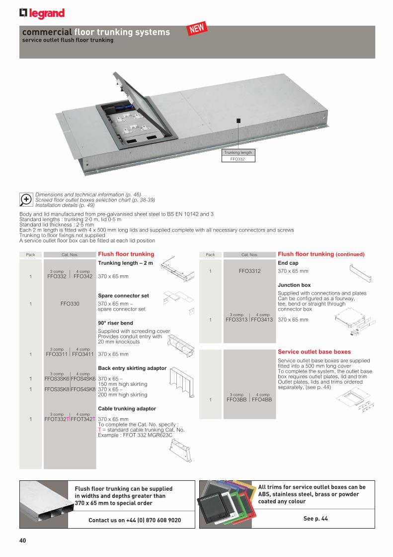
commercial floor trunking systemsservice outlet flush floor trunking
Pack Cat. Nos. Flushfloortrunking(continued)
Endcap
1 FFO3312 370 x 65 mm
Junctionbox
Supplied with connections and plates Can be configured as a fourway,
tee, bend or straight through connector box
3 comp 4 comp 1 FFO3313 FFO3413 370 x 65 mm
Serviceoutletbaseboxes
Service outlet base boxes are supplied fitted into a 500 mm long cover To complete the system, the outlet base box requires outlet plates, lid and trim Outlet plates, lids and trims ordered separately, (see p. 44)
3 comp 4 comp 1 FFO3BB FFO4BB
Pack Cat. Nos. Flushfloortrunking
Trunkinglength–2m
3 comp 4 comp 1 FFO332 FFO342 370 x 65 mm
Spareconnectorset
1 FFO330 370 x 65 mm – spare connector set
90°riserbend
Supplied with screeding cover Provides conduit entry with
20 mm knockouts 3 comp 4 comp 1 FFO3311 FFO3411 370 x 65 mm
Backentryskirtingadaptor 3 comp 4 comp 1 FFOS3SK6 FFOS4SK6 370 x 65 –
150 mm high skirting 1 FFOS3SK8 FFOS4SK8 370 x 65 –
200 mm high skirting
Cabletrunkingadaptor 3 comp 4 comp 1 FFOT332T FFOT342T 370 x 65 mm To complete the Cat. No. specify :
T = standard cable trunking Cat. No.Example : FFOT 332 MGR623C
Flush floor trunking can be supplied in widths and depths greater than 370 x 65 mm to special order
Contact us on +44 (0) 870 608 9020
Trunking length
FFO332
All trims for service outlet boxes can be ABS, stainless steel, brass or powder coated any colour
See p. 44
picto loupe-65765j.eps
Dimensions and technical information (p. 46) Screed floor outlet boxes selection chart (p. 38-39) Installation details (p. 49)
Body and lid manufactured from pre-galvanised sheet steel to BS EN 10142 and 3Standard lengths : trunking 2·0 m, lid 0·5 mStandard lid thickness : 2·5 mmEach 2 m length is fitted with 4 x 500 mm long lids and supplied complete with all necessary connectors and screwsTrunking to floor fixings not suppliedA service outlet floor box can be fitted at each lid position
NEW
040_Floor_2012 v5.indd 40 21/09/2012 16:42
41
commercial floor trunking systems shallow flush floor trunking
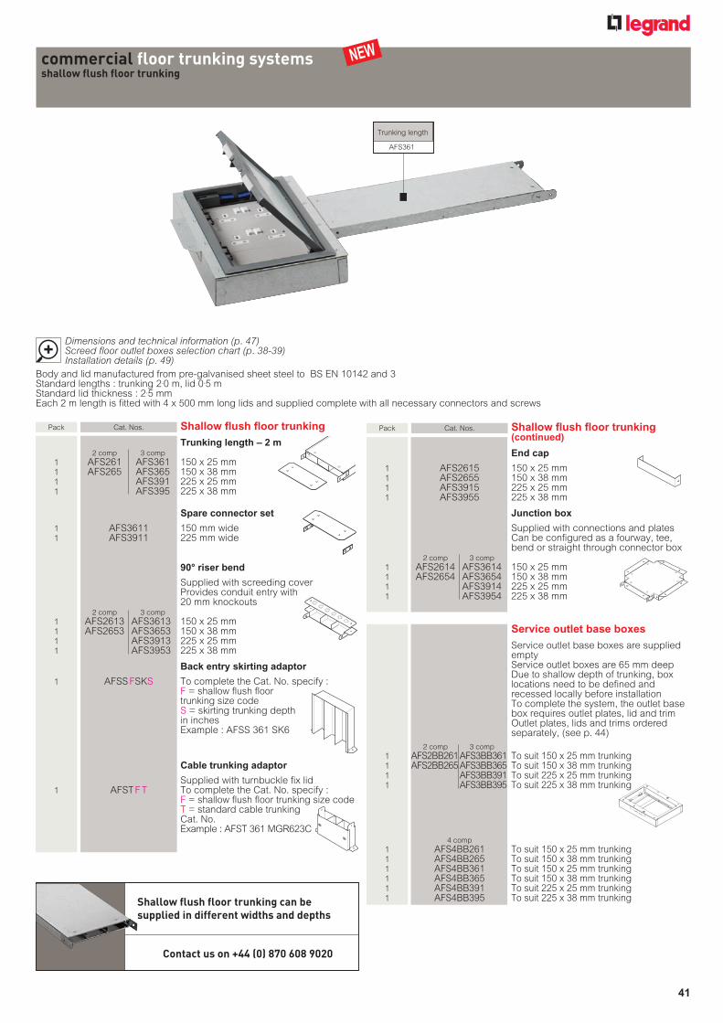
Pack Cat. Nos. Shallow flush floor trunking (continued)
End cap
1 AFS2615 150 x 25 mm 1 AFS2655 150 x 38 mm 1 AFS3915 225 x 25 mm 1 AFS3955 225 x 38 mm
Junction box
Supplied with connections and plates Can be configured as a fourway, tee,
bend or straight through connector box 2 comp 3 comp 1 AFS2614 AFS3614 150 x 25 mm 1 AFS2654 AFS3654 150 x 38 mm 1 AFS3914 225 x 25 mm 1 AFS3954 225 x 38 mm
Service outlet base boxes
Service outlet base boxes are supplied empty Service outlet boxes are 65 mm deep Due to shallow depth of trunking, box locations need to be defined and recessed locally before installation To complete the system, the outlet base box requires outlet plates, lid and trim Outlet plates, lids and trims ordered separately, (see p. 44)
2 comp 3 comp 1 AFS2BB261 AFS3BB361 To suit 150 x 25 mm trunking 1 AFS2BB265 AFS3BB365 To suit 150 x 38 mm trunking 1 AFS3BB391 To suit 225 x 25 mm trunking 1 AFS3BB395 To suit 225 x 38 mm trunking
4 comp 1 AFS4BB261 To suit 150 x 25 mm trunking 1 AFS4BB265 To suit 150 x 38 mm trunking 1 AFS4BB361 To suit 150 x 25 mm trunking 1 AFS4BB365 To suit 150 x 38 mm trunking 1 AFS4BB391 To suit 225 x 25 mm trunking 1 AFS4BB395 To suit 225 x 38 mm trunking
Pack Cat. Nos. Shallow flush floor trunking
Trunking length – 2 m 2 comp 3 comp 1 AFS261 AFS361 150 x 25 mm 1 AFS265 AFS365 150 x 38 mm 1 AFS391 225 x 25 mm 1 AFS395 225 x 38 mm
Spare connector set
1 AFS3611 150 mm wide 1 AFS3911 225 mm wide
90° riser bend
Supplied with screeding cover Provides conduit entry with
20 mm knockouts 2 comp 3 comp 1 AFS2613 AFS3613 150 x 25 mm 1 AFS2653 AFS3653 150 x 38 mm 1 AFS3913 225 x 25 mm 1 AFS3953 225 x 38 mm
Back entry skirting adaptor
1 AFSS FSKS To complete the Cat. No. specify :F = shallow flush floor trunking size codeS = skirting trunking depth in inches Example : AFSS 361 SK6
Cable trunking adaptor
Supplied with turnbuckle fix lid 1 AFST F T To complete the Cat. No. specify :
F = shallow flush floor trunking size codeT = standard cable trunking Cat. No.Example : AFST 361 MGR623C
Shallow flush floor trunking can be supplied in different widths and depths
Contact us on +44 (0) 870 608 9020
Trunking length
AFS361
Body and lid manufactured from pre-galvanised sheet steel to BS EN 10142 and 3Standard lengths : trunking 2.0 m, lid 0.5 mStandard lid thickness : 2.5 mmEach 2 m length is fitted with 4 x 500 mm long lids and supplied complete with all necessary connectors and screws
picto loupe-65765j.eps
Dimensions and technical information (p. 47) Screed floor outlet boxes selection chart (p. 38-39) Installation details (p. 49)
NEW
041_Floor_2012 v5.indd 41 21/09/2012 17:57
42
Underfloor duct can be supplied in other widths, depths and compartment configurations to special order
Contact us on +44 (0) 870 608 9020
commercial floor trunking systems underfloor duct
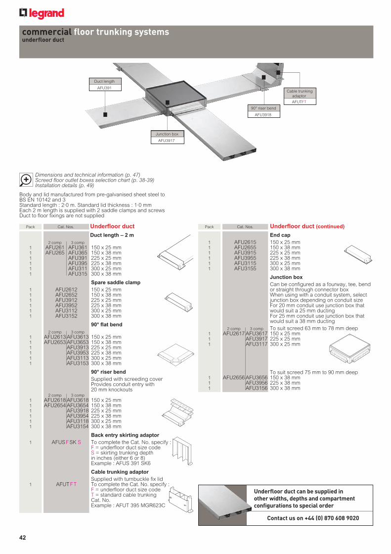
Pack Cat.Nos. Underfloorduct(continued)
Endcap 1 AFU2615 150x25mm 1 AFU2655 150x38mm 1 AFU3915 225x25mm 1 AFU3955 225x38mm 1 AFU3115 300x25mm 1 AFU3155 300x38mm
Junctionbox Canbeconfiguredasafourway,tee,bend
orstraightthroughconnectorboxWhenusingwithaconduitsystem,selectjunctionboxdependingonconduitsizeFor20mmconduitusejunctionboxthatwouldsuita25mmductingFor25mmconduitusejunctionboxthatwouldsuita38mmducting
2comp 3comp Tosuitscreed63mmto78mmdeep 1 AFU2617AFU3617 150x25mm 1 AFU3917 225x25mm 1 AFU3117 300x25mm
Tosuitscreed75mmto90mmdeep 1 AFU2656AFU3656 150x38mm 1 AFU3956 225x38mm 1 AFU3156 300x38mm
Bodyandlidmanufacturedfrompre-galvanisedsheetsteeltoBSEN10142and3Standardlength:2·0m.Standardlidthickness:1·0mmEach2mlengthissuppliedwith2saddleclampsandscrewsDucttofloorfixingsarenotsupplied
Pack Cat.Nos. Underfloorduct
Ductlength–2m 2comp 3comp 1 AFU261 AFU361 150x25mm 1 AFU265 AFU365 150x38mm 1 AFU391 225x25mm 1 AFU395 225x38mm 1 AFU311 300x25mm 1 AFU315 300x38mm
Sparesaddleclamp 1 AFU2612 150x25mm 1 AFU2652 150x38mm 1 AFU3912 225x25mm 1 AFU3952 225x38mm 1 AFU3112 300x25mm 1 AFU3152 300x38mm
90°flatbend 2comp 3comp 1 AFU2613AFU3613 150x25mm 1 AFU2653AFU3653 150x38mm 1 AFU3913 225x25mm 1 AFU3953 225x38mm 1 AFU3113 300x25mm 1 AFU3153 300x38mm
90°riserbend Suppliedwithscreedingcover Providesconduitentrywith
20mmknockouts 2comp 3comp 1 AFU2618AFU3618 150x25mm 1 AFU2654AFU3654 150x38mm 1 AFU3918 225x25mm 1 AFU3954 225x38mm 1 AFU3118 300x25mm 1 AFU3154 300x38mm
Backentryskirtingadaptor 1 AFUSFSKS TocompletetheCat.No.specify:
F=underfloorductsizecodeS=skirtingtrunkingdepthininches(either6or8)Example:AFUS391SK6
Cabletrunkingadaptor Suppliedwithturnbucklefixlid 1 AFUTFT TocompletetheCat.No.specify:
F=underfloorductsizecodeT=standardcabletrunkingCat.No.Example:AFUT395MGR623C
Ductlength
AFU391
90°riserbend
AFU3918
Junctionbox
AFU3917
Cabletrunkingadaptor
AFUTFT
picto loupe-65765j.eps
Dimensions and technical information (p. 47) Screed floor outlet boxes selection chart (p. 38-39) Installation details (p. 49)
042_043_Floor_2012 v5.indd 42 21/09/2012 13:05

43
Pack Cat. Nos. In-screed service outlet base boxes
Service outlet base boxes are supplied empty To complete the system, the outlet base box requires outlet plates, lid and trim Outlet plates, lids and trims ordered separately, (see p. 44) Use a 2 or 4 compartment service outlet box with 2 compartment duct 2 compartment box can only be used with 150 and 225 mm wide ducting
To fit 25 mm deep ducting To suit screed 63 mm to 78 mm deep 1 AFU2BB78 2 compartment to suit
25 mm shallow ducting 1 AFU3BB78 3 compartment to suit
25 mm shallow ducting 1 AFU4BB78 4 compartment to suit
25 mm shallow ducting
To fit 38 mm deep ducting To suit screed 75 mm to 90 mm deep 1 AFU2BB90 2 compartment box to suit
38 mm deep ducting 1 AFU3BB90 3 compartment box to suit
38 mm deep ducting 1 AFU4BB90 4 compartment box to suit
38 mm deep ducting
20 mm conduit fed To suit screed 63 mm to 78 mm deep 1 AFU1CON78 1 compartment box to suit
20 mm conduit 1 AFU2CON78 2 compartment box to suit
20 mm conduit 1 AFU3CON78 3 compartment box to suit
20 mm conduit 1 AFU4CON78 4 compartment box to suit
20 mm conduit
25 mm conduit fed To suit screed 75 mm to 90 mm deep 1 AFU1CON90 1 compartment box to suit
25 mm conduit 1 AFU2CON90 2 compartment box to suit
25 mm conduit 1 AFU3CON90 3 compartment box to suit
25 mm conduit 1 AFU4CON90 4 compartment box to suit
25 mm conduit
commercial floor trunking systems underfloor duct (continued)
picto loupe-65765j.eps
Dimensions and technical information (p. 47) Screed floor outlet boxes selection chart (p. 38-39) Installation details (p. 49)
Body and lid manufactured from pre-galvanised sheet steel to BS EN 10142 and 3Standard length : 2·0 m. Standard lid thickness : 1·0 mm Each 2 m length is supplied with 2 saddle clamps and screwsDuct to floor fixings are not supplied
Service outlet box 3 compartment
AFU3BB78
Service outlet box 2 compartment
AFU2BB78
pedestal units
picto loupe-65765j.eps
Dimensions and technical information (p. 50)
Pedestal units are available in other dimensions and finishes to special order
Contact us on +44 (0) 870 608 9020
PED8WHIPED3WHI
PED2WHI
NEW
Material : zinc coated mild steel to BS EN 10152Colour : white epoxy powder coated, RAL 9003. For other colours, please specify RAL numberZintec finish is available on request (Zintec pedestal units are to be painted on site)
Pack Cat. Nos. Pedestal units
1 PED1WHI Single socket
1 PED2WHI Twin socket
1 PED3WHI Back-to-back single sockets
1 PED4WHI Back-to-back twin sockets
1 PED8WHI Pyramid box
042_043_Floor_2012 v5.indd 43 21/09/2012 18:40
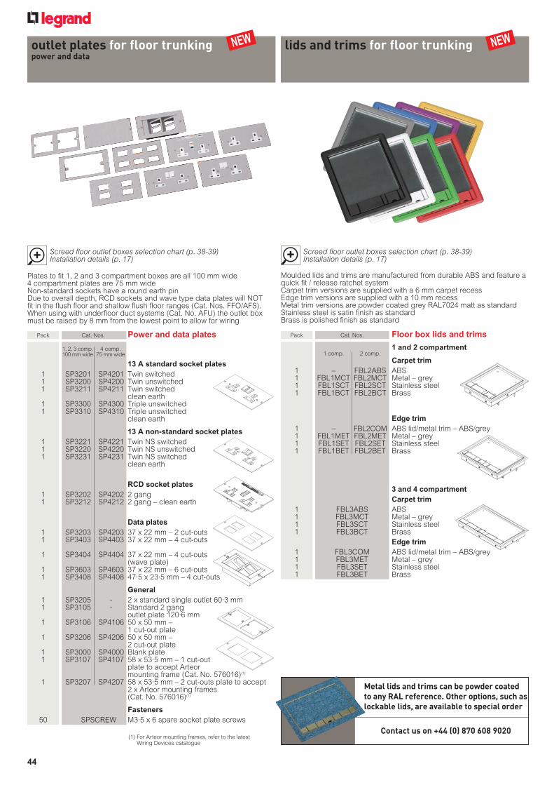
44
Pack Cat.Nos. Poweranddataplates
1,2,3comp. 4comp. 100mmwide 75mmwide
13Astandardsocketplates 1 SP3201 SP4201 Twinswitched 1 SP3200 SP4200 Twinunswitched 1 SP3211 SP4211 Twinswitched cleanearth 1 SP3300 SP4300 Tripleunswitched 1 SP3310 SP4310 Tripleunswitched
cleanearth
13Anon-standardsocketplates 1 SP3221 SP4221 TwinNSswitched 1 SP3220 SP4220 TwinNSunswitched 1 SP3231 SP4231 TwinNSswitched
cleanearth
RCDsocketplates 1 SP3202 SP4202 2gang 1 SP3212 SP4212 2gang–cleanearth
Dataplates 1 SP3203 SP4203 37x22mm–2cut-outs 1 SP3403 SP4403 37x22mm–4cut-outs
1 SP3404 SP4404 37x22mm–4cut-outs(waveplate)
1 SP3603 SP4603 37x22mm–6cut-outs 1 SP3408 SP4408 47·5x23·5mm–4cut-outs
General 1 SP3205 - 2xstandardsingleoutlet60·3mm 1 SP3105 - Standard2gang
outletplate120·6mm 1 SP3106 SP4106 50x50mm–
1cut-outplate 1 SP3206 SP4206 50x50mm–
2cut-outplate 1 SP3000 SP4000 Blankplate 1 SP3107 SP4107 58x53·5mm–1cut-out
platetoacceptArteormountingframe(Cat.No.576016)(1)
1 SP3207 SP4207 58x53·5mm–2cut-outsplatetoaccept2xArteormountingframes(Cat.No.576016)(1)
Fasteners 50 SPSCREW M3·5x6sparesocketplatescrews
picto loupe-65765j.eps
Screed floor outlet boxes selection chart (p. 38-39) Installation details (p. 17)
Platestofit1,2and3compartmentboxesareall100mmwide4compartmentplatesare75mmwideNon-standardsocketshavearoundearthpinDuetooveralldepth,RCDsocketsandwavetypedataplateswillNOTfitintheflushfloorandshallowflushfloorranges(Cat.Nos.FFO/AFS).Whenusingwithunderfloorductsystems(Cat.No.AFU)theoutletboxmustberaisedby8mmfromthelowestpointtoallowforwiring
outlet plates for floor trunkingpower and data
lids and trims for floor trunking
picto loupe-65765j.eps
Screed floor outlet boxes selection chart (p. 38-39) Installation details (p. 17)
MouldedlidsandtrimsaremanufacturedfromdurableABSandfeatureaquickfit/releaseratchetsystemCarpettrimversionsaresuppliedwitha6mmcarpetrecessEdgetrimversionsaresuppliedwitha10mmrecessMetaltrimversionsarepowdercoatedgreyRAL7024mattasstandardStainlesssteelissatinfinishasstandardBrassispolishedfinishasstandard
Metal lids and trims can be powder coated to any RAL reference. Other options, such as lockable lids, are available to special order
Contact us on +44 (0) 870 608 9020(1)ForArteormountingframes,refertothelatest
WiringDevicescatalogue
Pack Cat.Nos. Floorboxlidsandtrims
1and2compartment 1comp. 2comp. Carpettrim 1 – FBL2ABS ABS 1 FBL1MCT FBL2MCT Metal–grey 1 FBL1SCT FBL2SCT Stainlesssteel 1 FBL1BCT FBL2BCT Brass
Edgetrim 1 – FBL2COM ABSlid/metaltrim–ABS/grey 1 FBL1MET FBL2MET Metal–grey 1 FBL1SET FBL2SET Stainlesssteel 1 FBL1BET FBL2BET Brass
3and4compartment Carpettrim 1 FBL3ABS ABS 1 FBL3MCT Metal–grey 1 FBL3SCT Stainlesssteel 1 FBL3BCT Brass Edgetrim 1 FBL3COM ABSlid/metaltrim–ABS/grey 1 FBL3MET Metal–grey 1 FBL3SET Stainlesssteel 1 FBL3BET Brass
NEW NEW
044_Floor_2012 v5.indd 44 21/09/2012 13:40

45
Body and lid manufactured from pre-galvanised sheet steel to BS EN 10142 and 3Standard length : 2·0 mStandard lid thickness : 2·5 mmSupplied complete with all necessary connectors and screwsInternal dividers are fitted on all trunking lengths 225 mm and above to provide lid supportService outlet boxes are not available for this range
Pack Cat. Nos. Flush lid floor trunking
Trunking length – 2 m
1 FF42 100 x 50 mm 1 FF63 150 x 75 mm 1 FF124 300 x 100 mm
90° riser bend
Supplied with screeding cover Provides conduit entry with
20 mm knockouts
1 FFRB42 100 x 50 mm 1 FFRB63 150 x 75 mm 1 FFRB124 300 x 100 mm
End stop
1 FFEB42 100 x 50 mm 1 FFEB63 150 x 75 mm 1 FFEB124 300 x 100 mm
Junction box
Supplied with connectors and plates To be configured as a fourway, tee, bend or
straight through connector box
1 FFI42 100 x 50 mm 1 FFI63 150 x 75 mm 1 FFI124 300 x 100 mm
commercial floor trunking systems flush lid floor trunking
commercial floor trunking systems recessed lid floor trunking
Body and lid manufactured from pre-galvanised sheet steel to BS EN 10142 and 3Standard length : 2·0 m Standard lid thickness : 2·5 mmLid recess : 3·5 mmSupplied complete with all necessary connectors and screwsInternal dividers are fitted on all trunking lengths 225 mm and above to provide lid supportService outlet boxes are not available for this range
Pack Cat. Nos. Recessed lid floor trunking
Trunking length – 2 m
1 FRL42 100 x 50 mm 1 FRL63 150 x 75 mm 1 FRL124 300 x 100 mm
90° riser bend
Supplied with screeding cover Provides conduit entry with
20 mm knockouts
1 FRLRB42 100 x 50 mm 1 FRLRB63 150 x 75 mm 1 FRLRB124 300 x 100 mm
End stop
1 FRLEB42 100 x 50 mm 1 FRLEB63 150 x 75 mm 1 FRLEB124 300 x 100 mm
Junction box
Supplied with connectors and plates To be configured as a fourway, tee, bend or
straight through connector box
1 FRLI42 100 x 50 mm 1 FRLI63 150 x 75 mm 1 FRLI124 300 x 100 mm
Flush lid and recessed lid floor trunking can be supplied in other widths, depths and compartment configurations to special order
Contact us on +44 (0) 870 608 9020
Trunking length
FF63
picto loupe-65765j.eps
Dimensions and technical information (p. 48) Installation details (p. 49)
picto loupe-65765j.eps
Dimensions and technical information (p. 48) Installation details (p. 49)
Trunking length
FRFI63
045_Floor_2012 v4.indd 45 21/09/2012 18:55
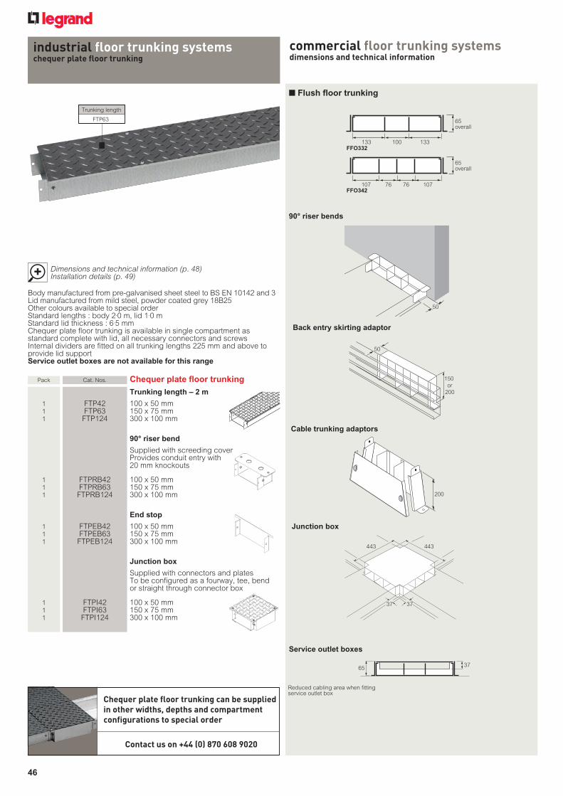
46
industrial floor trunking systems chequer plate floor trunking
Trunking length
FTP63
Chequer plate floor trunking can be supplied in other widths, depths and compartment configurations to special order
Contact us on +44 (0) 870 608 9020
Body manufactured from pre-galvanised sheet steel to BS EN 10142 and 3Lid manufactured from mild steel, powder coated grey 18B25 Other colours available to special orderStandard lengths : body 2.0 m, lid 1.0 mStandard lid thickness : 6.5 mmChequer plate floor trunking is available in single compartment as standard complete with lid, all necessary connectors and screwsInternal dividers are fitted on all trunking lengths 225 mm and above to provide lid supportService outlet boxes are not available for this range
picto loupe-65765j.eps
Dimensions and technical information (p. 48) Installation details (p. 49)
Pack Cat. Nos. Chequer plate floor trunking
Trunking length – 2 m
1 FTP42 100 x 50 mm 1 FTP63 150 x 75 mm 1 FTP124 300 x 100 mm
90° riser bend
Supplied with screeding cover Provides conduit entry with
20 mm knockouts
1 FTPRB42 100 x 50 mm 1 FTPRB63 150 x 75 mm 1 FTPRB124 300 x 100 mm
End stop
1 FTPEB42 100 x 50 mm 1 FTPEB63 150 x 75 mm 1 FTPEB124 300 x 100 mm
Junction box
Supplied with connectors and plates To be configured as a fourway, tee, bend
or straight through connector box
1 FTPI42 100 x 50 mm 1 FTPI63 150 x 75 mm 1 FTPI124 300 x 100 mm
commercial floor trunking systemsdimensions and technical information
n Flush floor trunking
Back entry skirting adaptor
90° riser bends
98 986767AFL342
AFL332120 12090
60overall
60overall
107 1077676FFO342
FFO332133 133100
65overall
65overall
150 or
200
50
150 or
200
50
Cable trunking adaptors
200
200
50
50
Service outlet boxes
6037
65 37
Junction box
37
403 403
37
37
443 443
37
Reduced cabling area when fitting service outlet box
046_050_Floor_2012 v4.indd 46 21/09/2012 13:57
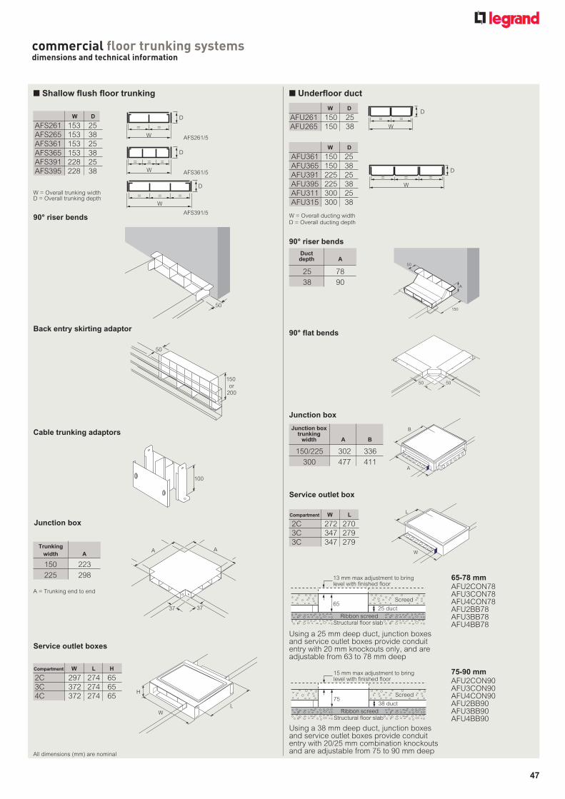
47
commercial floor trunking systemsdimensions and technical information
Back entry skirting adaptor
Service outlet boxes
150 or
200
50
150 or
200
50
Cable trunking adaptors
50
50
n Shallow flush floor trunking
= =
D
D
W
W
W
D
= = =
= = =
= =
D
D
W
W
W
D
= = =
= = =
90° riser bends
100
100
Junction box
60
330290
H
WL
37
AA
37
37
AA
37
W = Overall trunking widthD = Overall trunking depth
Trunking width A
150 223225 298
AFS261/5
AFS361/5
AFS391/5
A = Trunking end to end
All dimensions (mm) are nominal
AFS261 153 25AFS265 153 38AFS361 153 25AFS365 153 38AFS391 228 25AFS395 228 38
W D
2C 297 274 653C 372 274 654C 372 274 65
Compartment W L H
n Underfloor duct
150
50
A
150
50
A
50
5050
50
Ø6 HOLES
5050
90° riser bends
90° flat bends
Junction box
Service outlet box
15 ribbon screedStructural floor slab
60
15 max adjustment to bringlevel with finished floor
Screed
25 Trunking
15 ribbon screedStructural floor slab
75
15 max adjustment to bringlevel with finished floor
Screed
38 Trunking
A
302
Ribbon screedStructural floor slab
65
13 mm max adjustment to bringlevel with finished floor
Screed
25 duct
Ribbon screedStructural floor slab
75
15 mm max adjustment to bringlevel with finished floor
Screed
38 duct
A
B
303
221
15 ribbon screedStructural floor slab
60
15 max adjustment to bringlevel with finished floor
Screed
25 Trunking
15 ribbon screedStructural floor slab
75
15 max adjustment to bringlevel with finished floor
Screed
38 Trunking
W
L
15 ribbon screedStructural floor slab
60
15 max adjustment to bringlevel with finished floor
Screed
25 Trunking
15 ribbon screedStructural floor slab
75
15 max adjustment to bringlevel with finished floor
Screed
38 Trunking
15 ribbon screedStructural floor slab
60
15 max adjustment to bringlevel with finished floor
Screed
25 Trunking
15 ribbon screedStructural floor slab
75
15 max adjustment to bringlevel with finished floor
Screed
38 Trunking
A
302
Ribbon screedStructural floor slab
65
13 mm max adjustment to bringlevel with finished floor
Screed
25 duct
Ribbon screedStructural floor slab
75
15 mm max adjustment to bringlevel with finished floor
Screed
38 duct
A
B
Using a 25 mm deep duct, junction boxes and service outlet boxes provide conduit entry with 20 mm knockouts only, and are adjustable from 63 to 78 mm deep
65-78 mmAFU2CON78AFU3CON78AFU4CON78AFU2BB78AFU3BB78AFU4BB78
15 ribbon screedStructural floor slab
60
15 max adjustment to bringlevel with finished floor
Screed
25 Trunking
15 ribbon screedStructural floor slab
75
15 max adjustment to bringlevel with finished floor
Screed
38 Trunking
A
302
Ribbon screedStructural floor slab
65
13 mm max adjustment to bringlevel with finished floor
Screed
25 duct
Ribbon screedStructural floor slab
75
15 mm max adjustment to bringlevel with finished floor
Screed
38 duct
A
B
Using a 38 mm deep duct, junction boxes and service outlet boxes provide conduit entry with 20/25 mm combination knockouts and are adjustable from 75 to 90 mm deep
Duct depth A
25 7838 90
W = Overall ducting widthD = Overall ducting depth
= =
= = =
D
D
D
D
W= = =
W
W
W
= ==
= =
= = =
D
D
D
D
W= = =
W
W
W
= ==
= =
= = =
D
D
D
D
W= = =
W
W
W
= ==
= =
= = =
D
D
D
D
W= = =
W
W
W
= ==
Junction box trunking width A B
150/225 302 336 300 477 411
AFU261 150 25 AFU265 150 38
W D
75-90 mmAFU2CON90AFU3CON90AFU4CON90AFU2BB90AFU3BB90AFU4BB90
2C 272 270 3C 347 279 3C 347 279
Compartment W L
AFU361 150 25 AFU365 150 38 AFU391 225 25 AFU395 225 38 AFU311 300 25 AFU315 300 38
W D
046_050_Floor_2012 v4.indd 47 21/09/2012 13:57
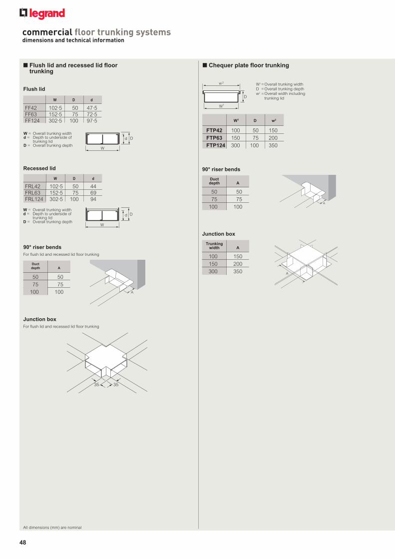
48
commercial floor trunking systemsdimensions and technical information
n Flush lid and recessed lid floor trunking
D
W
d
D
W
dW = Overall trunking widthd = Depth to underside of
trunking lidD = Overall trunking depth
90° riser bendsFor flush lid and recessed lid floor trunking
A
A
Duct depth A
50 50 75 75100 100
Junction box For flush lid and recessed lid floor trunking
3535
3535
Recessed lid
W = Overall trunking widthd = Depth to underside of
trunking lidD = Overall trunking depth
D
W
d
D
W
d
FF42 102·5 50 47·5 FF63 152·5 75 72·5 FF124 302·5 100 97·5
W D d
Flush lid
FRL42 102·5 50 44 FRL63 152·5 75 69 FRL124 302·5 100 94
W D d
All dimensions (mm) are nominal
n Chequer plate floor trunking
90° riser bends
Junction box
W1 = Overall trunking widthD = Overall trunking depthw2 = Overall width including
trunking lid
A
A
WIDTHWIDTH
A
D
W
d
D
W
w2
1
W1 D w2
FTP42 100 50 150FTP63 150 75 200FTP124 300 100 350
Duct depth A
50 50 75 75100 100
Trunking width A
100 150150 200300 350
046_050_Floor_2012 v4.indd 48 21/09/2012 18:28

49
n Installation details
Shallow Flush Floor Trunkingin screeded floor
New Installation
New Installation
Retrofit
New Installation
Retrofit
Underfloor Ductingin screeded floor
Structural floor slab
Ribbon screed
Flush Floor Trunkingin screeded floor
65 mm
Structural floor slab
Ribbon screed
65 mm
330 mm
Sufficient width to permit screwdriver access to the sides
Sufficient width to permit screwdriver access to the sides
Structural floor slab Slab may need removing toaccept service outlet box
Ribbon screed
25 or 38 mm60 mm
Structural floor slab
Ribbon screed
Structural floor slab Slab may need removing toaccept Service Outlet Box
Ribbon screed
25 or 38 mm
Minimum 30 mmscreed above ducting
Maximum 15 mm adjustment
Service outlet box / junction boxadjust height to final finished floorlevel before pouring screed
60 mm
25 or 38 mm
Flush lid floor trunking in screeded floor
Cavity Floor Trunking
Off Set Tee / Four Way
3·5 mm deep recess
Recommended minimumscreed depth =trunking depth
plus nominal 15 mm
Structural floor slab
Ribbon screed
Recessed Lid Trunkingin screeded floor
New Installation
New Installation
New InstallationFlush Lid Trunkingin screeded floor
Recommended minimumscreed depth =trunking depth
plus nominal 15 mm
Structural floor slab
Ribbon screed
Recommended minimumscreed depth =trunking depth
plus nominal 15 mm
Structural floor slab
Ribbon screed
Chequer Plate Floor Trunkingin screeded floor
When fitting Off Set Tee / Four Waya cavity depth of more than 105 mm is needed
105 mm
Chequer plate floor trunking in screeded floor
Cavity Floor Trunking
Off Set Tee / Four Way
3·5 mm deep recess
Recommended minimumscreed depth =trunking depth
plus nominal 15 mm
Structural floor slab
Ribbon screed
Recessed Lid Trunkingin screeded floor
New Installation
New Installation
New InstallationFlush Lid Trunkingin screeded floor
Recommended minimumscreed depth =trunking depth
plus nominal 15 mm
Structural floor slab
Ribbon screed
Recommended minimumscreed depth =trunking depth
plus nominal 15 mm
Structural floor slab
Ribbon screed
Chequer Plate Floor Trunkingin screeded floor
When fitting Off Set Tee / Four Waya cavity depth of more than 105 mm is needed
105 mm
Recessed lid floor trunking in screeded floor
Cavity Floor Trunking
Off Set Tee / Four Way
3·5 mm deep recess
Recommended minimumscreed depth =trunking depth
plus nominal 15 mm
Structural floor slab
Ribbon screed
Recessed Lid Trunkingin screeded floor
New Installation
New Installation
New InstallationFlush Lid Trunkingin screeded floor
Recommended minimumscreed depth =trunking depth
plus nominal 15 mm
Structural floor slab
Ribbon screed
Recommended minimumscreed depth =trunking depth
plus nominal 15 mm
Structural floor slab
Ribbon screed
Chequer Plate Floor Trunkingin screeded floor
When fitting Off Set Tee / Four Waya cavity depth of more than 105 mm is needed
105 mm
Flush floor trunking in screeded floor
Shallow flush floor trunking in screeded floor
Underfloor duct in screeded floor
046_050_Floor_2012 v4.indd 49 21/09/2012 14:00
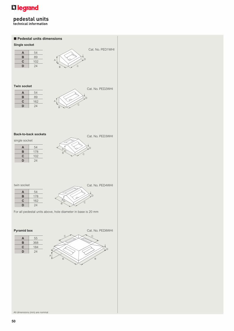
50
pedestal unitstechnical information
All dimensions (mm) are nominal
Twin socket
BC
DA
89162
24
54
BC
DA
A 54 B 89 C 162 D 24
Single socket
B C
DA
89 102
2454
B C
DA
A 54 B 89 C 102 D 24
Pyramid box
B
CC
B
D
A
B
CC
B
D
A
A 55 B 368 C 184 D 24
Back-to-back sockets
B C
DA
178 102
2454
B C
DA A 54 B 178 C 102 D 24
single socket
B C
D
A
178162
24
54
B C
D
A
A 54 B 178 C 162 D 24
twin socket
n Pedestal units dimensions
For all pedestal units above, hole diameter in base is 20 mm
Cat. No. PED1WHI
Cat. No. PED2WHI
Cat. No. PED3WHI
Cat. No. PED4WHI
Cat. No. PED8WHI
046_050_Floor_2012 v4.indd 50 21/09/2012 14:00

Protection classificationsProtection against solid bodies and liquids : Index of protection - IP xx Protection against mechanical impact :
Index of protection - IK
1st figure :protection against solid bodies
IP tests
0 No protection
1
2
3
4
5
6
Ø 50 mm
s52/01/95F
Ø 12·5 mm
s52/02/95F
Ø 2·5 mm
s52/03/95F
Ø 1 mm
s52/04/95F
s52/05/95F
s52/06/95F
Protected against solidbodies of 50 mm andgreater (e.g. accidental contact with the hand)
Protected against solidbodies of 12·5 mm and greater (e.g. finger)
Protected against solidbodies of 2·5 mm and greater (e.g. tools, wires)
Protected against dust(no harmful deposit)
Completely protected against dust
Protected against solidbodies larger than 1 mm(e.g. thin tools andfine wires)
2nd figure :protection against liquids
IP tests
0 No protection
1
2
3
4
5
6
7
8
s52/07/95F
15°
s52/08/95F
60°
s52/09/95F
Protected againstvertically falling dropsof water (condensation)
Protected against drops of water falling up to 15° from the vertical
Protected against water sprayed up to 60° from the verticals52/10/95F
Protected againstsplashing water from all directionss52/11/95F
Protected against jets of water from all directionss52/12/95F
Protected against powerful jets of water from all directions
15 c
m m
in.
s52/13/95F
1 m
Protected against the effects of temporary immersion in water
m
s52/14/95F
Protected against thecontinuous effects ofimmersion in water having regard to specific conditions
The contents of the Protection Classifications charts are for guidance only. If you have any doubt as to the interpretation of the information contained therein, please refer either to the standard itself or contact Legrand.
Statement to Purchasers and Prospective Purchasers1. Section 6 of this Act provides that manufacturers, designers, importers or suppliers of articles for use at work have a dutyto ensure so far as is reasonably practical, that the article will be safe and without risk to health when properly used. An article is not regarded as being ‘properly used’ if it is used without regard to any relevant information or advice relating to its use made available by the manufacturer, designer, importer or supplier.
2. With regard to these provisions the following is given as a guide to the information which is readily available to you. This information relates to those products detailed in our catalogue(s) or associated literature or may be obtained by specific request to the Company.
3. All products should be installed and maintained in accordance with good engineering practice and relevant British or
other applicable standards, regulations for the installation of equipment by the Institute of Electrical Engineers or any other applicable Codes of Practice.
Health and Safety at Work Act
The Electricity at WorkRegulations, 1989
1. All installations and maintenance should be carried out within the provision of the above Act and by persons so qualified as defined in the Act.
2. Information and advice on the suitability of our products can be obtained from Legrand Electric Limited on specific request.
Conditions of salePlease consult our current price list
According to standards IEC 62262 andBS EN 62262
For information concerning wiring device standards outside the UK contact :
BSI
Customer Services
09:00 to 17:00 – Monday to Friday
Tel : +44 (0) 20 8996 9001
Fax : +44 (0) 20 8996 7001
Email : [email protected]
marking appears on electrical or electronic products from Legrand and enables the circulation of goods outside the UK.
Health and Safety at Work, etc. Act. 1974
In accordance with its policy of continuous improvement the Company reserves the right to change specifications and designs without notice. All illustrations, descriptions, dimensions and weights in this catalogue are for guidance and cannot be held binding on the Company.
75 mm0.2 kg
100 mm0.2 kg
175 mm0.2 kg
250 mm0.2 kg
350 mm0.2 kg
200 mm0.5 kg
400 mm0.5 kg
295 mm1.7 kg
200 mm5 kg
5 kg400 mm
IK TestsImpactenergy
(in Joules)
IK 00
IK 01
IK 02
IK 03
IK 04
IK 05
IK 06
IK 07
IK 08
IK 09
IK 10
0
0·15
0·2
0·35
0·5
0·7
1
2
5
10
20
(1) A product previously classed as IP xx-7 can be assumed to fulfill the conditions of an IP xx - IK 08
This table can be used to ascertain the resistance of a product to an impact given in Joules from the IK code (graduated from 00 to 10).It can also be used to ascertain the correspondence with the old IP code 3rd digit and the corresponding external “Ag” conditions.
Degree of protection of enclosures of electrical equipment in accordance with standards IEC 60529, BS EN 60529Up to 1 000 V± and 1 500 V=
CELOGO-001�black
051_Floor_2012 v1.indd 51 21/09/2012 18:27

Floo
r sy
stem
s te
chni
cal g
uide
10/
2012
.3.5
kHead office (UK and Ireland):Legrand Electric LimitedGreat King Street North, Birmingham, B19 2LFTel: +44 (0) 870 608 9000 Fax: +44 (0) 870 608 9004Website: www.legrand.co.uk
The Legrand logo is a registered trademark of the Legrand group of companies.
Contact details United Kingdom
Great King Street North, Birmingham, B19 2LF
Customer Sevices: Tel: +44 (0) 845 605 4333 Fax: +44 (0) 845 605 4334E-mail: [email protected]
Quotations and Technical Support: Tel: +44 (0) 870 608 9020 Fax: +44 (0) 845 605 5334 E-mail: [email protected]
Republic of Ireland: Tel: 01 295 9673 Fax: 01 295 4671E-mail: [email protected]
Distributor:
This document is printed on sustainably sourced paper. Please recycle.
Feature Pages.indd 10 21/09/2012 18:01