

New Additions to the Ball Nose Line - Duralitte
17
Transcript of New Additions to the Ball Nose Line - Duralitte


•• Carbide Core Modular Extensions These extensions complement our existing Modular Heads and Extensions.Carbide core provides enhanced vibration dampening capability, reduceddeflection and improved rigidity. Optional add-on extensions available.See page 10 for more information.
With the purchase of Dapra Ball Nose, Flat Bottom, Back Draft and High-FeedInserts, receive FREE or discounted replacement Ball Nose, Back Draft and Flat Bottom Cutters!*
Ball Nose, Flat Bottom and Back DraftAutomatic Cutter Replacement Program
Application Information 13Feed, Speed & Diameter Compensation 14Troubleshooting Information 15Anti-Seize Grease Application 15Recommended Cutting Speeds 16
Insert Ordering Information 3-5Insert Grade Selection 5Cutter Body Ordering Information 6-9, 12Screw-on Heads & Modular Extensions 10-11Spare Parts & Tools 12
2
New Additions tothe Ball Nose Line
Index
Here’s how it works:
FBR-N
Every time you buy 30 insertsDapra will give you a FREE corresponding Steel cutter body.*
OR
Dapra will give you 50% OFF the purchase of any replacementCarbide Core or Solid Carbide Shank tool.*
* Notes: CUTTER SELECTION MUST BE INDICATED AT TIME OF ORDER
Insert sizes can be mixed, however the FREE cutter body must accommodate the smallest insert size ordered. For example, ordering twenty 3/4" inserts and ten 1/2" inserts entitles the purchaser to a FREE 1/2" Steel cutter body.FREE or half-price holders are not eligible for exchange once order is filled.
BDR-N
HFBD
HBN
BNR-N
BNR-CB
BDR-CB
FBR-CB
Terms and Conditions:• Pertains to Ball Nose, Back Draft, Flat Bottom and High-Feed cutting tool products only.• Product must be drop shipped to end user only.• Dapra reserves the right to cancel program without notice.• Blanket orders and specials are not eligible for this program.

1 2 33Three Steps to Quick & Easy Ordering
With three quick steps and plenty of insert andcutter choices, Dapra makes it easy to find exactlywhat you need and get your cutting tools on time.
Refer to back cover for speed recommendations by material.
More insert options follow on page 4.
3
Step One: Choose Your Inserts
Step Two: Choose Your Insert Grade
Step Three: Choose Your Cutter Body
1Step One: Choose Your Inserts
• Smoother cutting action• Reduced chatter• Cleaner surface finish• Heavier cutting capability
• Increased metal removal• Reduced stress on work materials• Reduced tool pressure and heat• Longer tool life
HBN Series – Helical Cutting Edge Ball Nose Inserts*
Optimize performance in all Ball Nose applications:
* For insert grades and coatings, see chart on page 5.
D Ø
3/8"
1/2"5/8"
3/4"
1"
11/4"
DiameterHelical(HBN)
HBN-0375
HBN-0500
HBN-0625
HBN-0750
HBN-1000
HBN-1250
10mm
12mm
16mm
20mm
25mm
30mm
32mm
HBN-10MM
HBN-12MM
HBN-16MM
HBN-20MM
HBN-25MM
HBN-30MM
HBN-32MM
Metric

D Ø
3/8"1/2"5/8"3/4"
1"
11/4"
DiameterWithout
Chipbreaker
BNR-0375-N
BNR-0500-N
BNR-0625-N
BNR-0750-N
BNR-1000-N
BNR-1250-N
10mm
12mm
16mm
20mm
25mm
30mm
32mm
BNR-10MM-N
BNR-12MM-N
BNR-16MM-N
BNR-20MM-N
BNR-25MM-N
BNR-30MM-N†
BNR-32MM-N
Metric Without Chipbreaker
Standard Ball Nose Inserts
D Ø
5/16"3/8"1/2"5/8"3/4"
1"
11/4"
DiameterChipbreaker
BNR-0312-CB
BNR-0375-CB
BNR-0500-CB
BNR-0625-CB
BNR-0750-CB
BNR-1000-CB
BNR-1250-CB
8mm
10mm
12mm
16mm
20mm
25mm
32mm
BNR-08MM-CB
BNR-10MM-CB
BNR-12MM-CB
BNR-16MM-CB
BNR-20MM-CB
BNR-25MM-CB
BNR-32MM-CB
Metric Chipbreaker
D ØDiameter
3/8"1/2"5/8"3/4"
1"
Chipbreaker
FBR-0500-CBFBR-0625-CB
FBR-0750-CB
FBR-1000-CB
WithoutChipbreaker
FBR-0375-N
FBR-0500-NFBR-0625-N
FBR-0750-N
FBR-1000-N
Corner Radius1/32
✓✓✓✓✓
1/16
✓✓✓✓
1/8
✓
FBR-CB
BDR-CB
BDR-PCD
D ØDiameter
3/8"1/2"5/8"3/4"
1"
Chipbreaker
BDR-0500-CB
BDR-0625-CB
BDR-0750-CB
BDR-1000-CB
WithoutChipbreaker
BDR-0375-N
BDR-0500-N
BDR-0625-N
BDR-0750-N
BDR-1000-N
Corner Radius1/32
✓✓✓✓✓
1/16
✓✓✓✓✓
1/8
✓(CB)
✓(CB)
✓
D ØDiameter
3/8"1/2"3/4"
WithoutChipbreaker
BDR-0375-N-PCD
BDR-0500-N-PCD
BDR-0750-N-PCD
Corner Radius1/32
✓✓✓
1/16
✓✓
Flat Bottom (FBR) Inserts
Back Draft (BDR) Inserts (back draft angle: 7˚ per side)
PCD-Tipped Inserts**
FBR-N
BDR-N
**Note: DOC of PCD-Tipped Inserts is .125"
† Use BNEM 1250 cutter body and size 32 insert screws.
BNR-N
BNR-CB
1Step One: Choose Your Inserts
4
NEW
RAD
.062 (Flat Before 7˚ Back Draft)
7.00˚
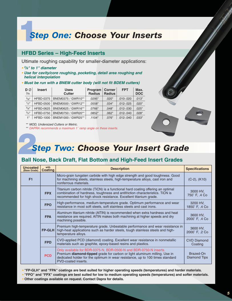
5
D ØDia.
3/8"1/2"5/8"3/4"
1"
Insert
HFBD-0375
HFBD-0500
HFBD-0625
HFBD-0750
HFBD-1000
• 3/8" to 1" diameter• Use for cavity/core roughing, pocketing, detail area roughing and
helical interpolation• Must be run with a BNEM cutter body (will not fit BDEM cutters)
HFBD Series – High-Feed Inserts
Ultimate roughing capability for smaller-diameter applications:
UsesCutter
BNEM0375 / GWR10**
BNEM0500 / GWR12**
BNEM0625 / GWR16**
BNEM0750 / GWR20**
BNEM1000 / GWR25**
CornerRadius
.020"
.034"
.048"
.062"
.076"
FPT
.010-.020
.012-.025
.012-.030
.012-.040
.012-.040
Max.DOC.013"
.020"
.025"
.028"
.033"
ProgramRadius.0295"
.0558"
.0766"
.0852"
.1104"
** MOD, Undersized Cutters or Metric.** DAPRA recommends a maximum 1˚ ramp angle on these inserts.
• "FP-GLH" and "FPA" coatings are best suited for higher operating speeds (temperatures) and harder materials.• "FPO" and "FPX" coatings are best suited for low to medium operating speeds (temperatures) and softer materials.• Other coatings available on request. Contact Dapra for details.
Ball Nose, Back Draft, Flat Bottom and High-Feed Insert Grades
Description
Micro-grain tungsten carbide with high edge strength and good toughness. Goodfor machining steels, stainless steels, high-temperature alloys, cast iron andnonferrous materials.
Titanium carbon nitride (TiCN) is a functional hard coating offering an optimalcombination of hardness, toughness and antifriction characteristics. TiCN isrecommended for high shock resistance. Excellent titanium grade.
High-performance, medium-temperature grade. Optimum performance and wearresistance in most soft steels, soft stainless steels and cast irons.
Aluminum titanium nitride (AlTiN) is recommended when extra hardness and heatresistance are required. AlTiN makes both machining at higher speeds and drymachining possible.
Premium high-temperature grade. Unbeatable performance and wear resistance inhigh-heat applications such as harder steels, tough stainless steels and high-temperature alloys.
CVD-applied PCD (diamond) coating. Excellent wear resistance in nonmetallicmaterials such as graphite, epoxy-based resins and plastics.
Only available for BDR-0375-N, BDR-0500-N and BDR-0750-N inserts.Premium diamond-tipped grade for carbon or light aluminum milling. Use indedicated holder for the optimum in wear resistance, up to 100 times standardPVD-coated inserts.
Specifications
(C-2), (K10)
3000 HV, 750˚ F, .4 Co
3200 HV, 1850˚ F, .4 Co
3600 HV, 2000˚ F, .4 Co
3600 HV,2000˚ F, .2 Co
CVD DiamondCoating
Brazed-OnDiamond Tips
Uncoated(Base Grade)
F1
withCoating
FPX
FPO
FPA
FP-GLH
FPD
PCD
2Step Two: Choose Your Insert Grade
1Step One: Choose Your Inserts

CC-BNEM-0750-7000-SS
CC-BNEM-0750-8250-SS
CC-BNEM-1000-6250-SS
CC-BNEM-1000-7500-SS
CC-BNEM-1000-9000-SS
CC-BNEM-1250-7000-SS
CC-BNEM-1250-9000-SS
0.750"
0.750"
1.000"
1.000"
1.000"
1.250"
1.250"
0.670"
0.670"
0.860"
0.860"
0.860"
1.070"
1.070"
1.000"
1.000"
1.500"
1.500"
1.500"
1.750"
1.750"
0.740"
0.740"
0.990"
0.990"
0.990"
1.240"
1.240"
0.750"
0.750"
1.000"
1.000"
1.000"
1.250"
1.250"
3.000"
4.500"
2.000"
3.750"
5.000"
2.500"
4.500"
1.031˚
0.573˚
7.400˚
1.661˚
1.088˚
6.447˚
1.775˚
7.000"
8.250"
6.250"
7.500"
9.000"
7.000"
9.000"
Part Number Cutting Dia. AØ
BStraightLength
CTaper End Ø
DShank
Ø
EEffectiveLength
TTaperAngle
LOverallLength
Carbide Core Ball Nose End Mills – Standard Shank
3Step Three: Choose Your Cutter Body
6
BNEM-0500-3500-SS
BNEM-0500-5250-SS
BNEM-0500-6000-SS
SE-BNEM-0500-7000-SS
BNEM-0625-5500-SS
BNEM-0625-6250-SS
SE-BNEM-0625-7000-SS
BNEM-0750-4500-SS
BNEM-0750-7000-SS
BNEM-0750-8250-SS
SE-BNEM-0750-9000-SS
BNEM-1000-6250-SS
BNEM-1000-7500-SS
BNEM-1000-9000-SS
SE-BNEM-1000-10000-SS
BNEM-1250-7000-SS
BNEM-1250-9000-SS
0.500"
0.500"
0.500"
0.500"
0.625"
0.625"
0.625"
0.750"
0.750"
0.750"
0.750"
1.000"
1.000"
1.000"
1.000"
1.250"
1.250"
0.413"
0.413"
0.413"
0.413"
0.547"
0.547"
0.547"
0.670"
0.670"
0.670"
0.670"
0.860"
0.860"
0.860"
0.860"
1.070"
1.070"
0.750"
0.750"
0.750"
0.750"
0.750"
0.750"
0.750"
1.000"
1.000"
1.000"
1.000"
1.500"
1.500"
1.500"
1.500"
1.750"
1.750"
0.490"
0.490"
0.490"
0.490"
0.615"
0.615"
0.615"
0.740"
0.740"
0.740"
0.740"
0.990"
0.990"
0.990"
0.990"
1.240"
1.240"
0.500"
0.500"
0.500"
0.500"
0.625"
0.625"
0.625"
0.750"
0.750"
0.750"
.0750"
1.000"
1.000"
1.000"
1.000"
1.250"
1.250"
1.250"
2.000"
2.500"
1.210"
1.380"
2.500"
1.340"
1.750"
3.000"
4.500"
1.710"
2.000"
3.750"
5.000"
1.940"
2.500"
4.500"
4.400˚
1.775˚
1.000˚
4.400˚
3.090˚
1.088˚
3.100˚
2.690˚
1.030˚
0.573˚
2.700˚
7.400˚
1.660˚
1.088˚
7.400˚
6.447˚
1.775˚
3.500"
5.250"
6.000"
7.000"
5.500"
6.250"
7.000"
4.500"
7.000"
8.250"
9.000"
6.250"
7.500"
9.000"
10.000"
7.000"
9.000"
Part Number Cutting Dia. AØ
BStraightLength
CTaper End Ø
DShank
Ø
EEffectiveLength
TTaperAngle
LOverallLength
Ball Nose End Mills – Standard Shank
STANDARD SHANKTools starting with "SE" are short
effective-reach cutters, designed foroptimum strength and limited clearance
Optimize performance with Carbide Core tooling:• reduced deflection • increased stiffness
• less chatter
Achieve Higher Performance withCarbide Core Cutter Bodies!
L
B
C
E
D
CuttingDia.
A
L
B
C
E
D
Cutting Dia.
A
*Note: All Dapra Ball Nose end mills accept either inch or metric inserts of like sizes.Example: BNEM0750 and GWR20 accept either a 3/4" or 20mm diameter insert.
BNEM0500 and GWR12 accept either a 1/2" or 12mm diameter insert.

Carbide Core Ball Nose End Mills – Oversized Shank
CC-BNEM-0750-7500-OS
CC-BNEM-0750-9500-OS
CC-BNEM-1000-8250-OS
CC-BNEM-1000-10000-OS
CC-BNEM-1000-12000-OS
CC-BNEM-1000-15000-OS
CC-BNEM-1250-11000-OS
0.750"
0.750"
1.000"
1.000"
1.000"
1.000"
1.250"
0.670"
0.670"
0.860"
0.860"
0.860"
0.860"
1.070"
1.000"
1.000"
1.500"
1.500"
1.500"
1.500"
1.750"
0.740"
0.740"
0.990"
0.990"
0.990"
0.990"
1.240"
1.000"
1.000"
1.250"
1.250"
1.250"
1.250"
1.500"
3.500"
4.500"
4.500"
4.500"
6.500"
6.500"
7.500"
0.802˚
0.573˚
1.260˚
1.260˚
0.750˚
0.750˚
0.859˚
7.500"
9.500"
8.250"
10.000"
12.000"
15.000"
11.000"
Part Number Cutting Dia. AØ
BStraightLength
CTaper End Ø
DShank
Ø
EEffectiveLength
TTaperAngle
LOverallLength
OVERSIZED SHANK3Step Three: Choose Your Cutter Body
BNEM-0313-5500-OS
BNEM-0375-3500-OS
BNEM-0375-6000-OS
SE-BNEM-0375-6000-OS
BNEM-0500-6000-OS
SE-BNEM-0500-6000-OS
BNEM-0625-7000-OS
BNEM-0750-7500-OS
BNEM-0750-9500-OS
SE-BNEM-0750-9500-OS
BNEM-1000-8250-OS
SE-BNEM-1000-9500-OS
BNEM-1000-10000-OS
BNEM-1250-11000-OS
0.313"
0.375"
0.375"
0.375"
0.500"
0.500"
0.625"
0.750"
0.750"
0.750"
1.000"
1.000"
1.000"
1.250"
0.280"
0.335"
0.335"
Tapered
0.414"
Tapered
0.547"
0.670"
0.670"
Tapered
0.860"
Tapered
0.860"
1.070"
0.625"
0.625"
0.625"
n/a
0.750"
n/a
0.750"
1.000"
1.000"
n/a
1.500"
n/a
1.500"
1.750"
0.415"
0.365"
0.365"
n/a
0.490"
n/a
0.615"
0.740"
0.740"
n/a
0.990"
n/a
0.990"
1.240"
0.500"
0.500"
0.500"
0.500"
0.625"
0.625"
0.750"
1.000"
1.000"
1.000"
1.250"
1.250"
1.250"
1.500"
1.910"
1.340"
1.880"
1.380"
2.500"
2.310"
3.130"
3.500"
4.500"
3.000"
4.500"
3.880"
4.500"
6.000"
3.000˚
1.200˚
0.688˚
3.000˚
1.260˚
3.000˚
0.802˚
0.802˚
0.573˚
3.000˚
1.260˚
3.000˚
0.022˚
1.146˚
5.500"
3.500"
6.000"
5.880"
6.000"
6.000"
7.000"
7.500"
9.500"
9.440"
8.250"
9.440"
10.000"
11.000"
Part Number Cutting Dia. AØ
BStraightLength
CTaper End Ø
DShank
Ø
EEffectiveLength
TTaperAngle
LOverallLength
Ball Nose End Mills – Oversized Shank
More cutter options follow on page 8.
7
Optimize performance with Carbide Core tooling:• reduced deflection • increased stiffness
• less chatter
Achieve Higher Performance withCarbide Core Cutter Bodies!
Tools starting with "SE" are shorteffective-reach cutters, designed for
optimum strength and limited clearance
L
B
C
E
D
CuttingDia.
A
L
B
C
E
D
Cutting Dia.
A
*Note: All Dapra Ball Nose end mills accept either inch or metric inserts of like sizes.Example: BNEM0750 and GWR20 accept either a 3/4" or 20mm diameter insert.
BNEM0500 and GWR12 accept either a 1/2" or 12mm diameter insert.

8
SC-BNEM-0375-3950-SS2
SC-BNEM-0375-7000-SS2
SC-BNEM-0500-3950-SS2
SC-BNEM-0500-6500-SS2
SC-BNEM-0500-7000-SS2
SC-BNEM-0500-7000-12MM-SS2
SC-BNEM-0625-7000-SS2
SC-BNEM-0750-7500-SS2
SC-BNEM-0750-10000-SS2
SC-BNEM-0750-10000-18MM-SS2
SC-BNEM-1000-7500-SS2
SC-BNEM-1000-10000-SS2
SC-BNEM-1000-10000-25MM-SS2
0.375"
0.375"
0.500"
0.500"
0.500"
0.500"
0.625"
0.750"
0.750"
0.750"
1.000"
1.000"
1.000"
0.335"
0.335"
0.413"
0.413"
0.413"
0.413"
0.547"
0.670"
0.670"
0.670"
0.860"
0.860"
0.860"
0.625"
0.625"
0.750"
0.750"
0.750"
0.500"
0.750"
1.000"
1.000"
1.000"
1.500"
1.500"
1.500"
0.365"
0.365"
0.490"
0.490"
0.490"
0.490"
0.615"
0.740"
0.740"
0.740"
0.990"
0.990"
0.990"
0.375"
0.375"
0.500"
0.500"
0.500"
12mm
0.625"
0.750"
0.750"
18mm
1.000"
1.000"
25mm
1.500"
3.000"
1.500"
3.500"
4.000"
1.450"
4.000"
2.250"
6.000"
2.250"
3.000"
7.000"
3.000"
0.516˚
0.172˚
2.920˚
0.800˚
0.688˚
1.500˚
0.500˚
1.600˚
0.400˚
1.600˚
2.500˚
0.670˚
2.500˚
3.950"
7.000"
3.950"
6.500"
7.000"
7.000"
7.000"
7.500"
10.000"
10.000"
7.500"
10.000"
10.000"
Part Number Cutting Dia. AØ
BStraightLength
CTaper End Ø
DShank
Ø
EEffectiveLength
TTaperAngle
LOverallLength
Solid Carbide Ball Nose End Mills – Standard Shank
See page 5 foravailable insert
grades.
Optimize performance with Carbide Shank tooling:• reduced deflection • increased stiffness • less chatter
• heat shrink toolholding capability (Ball Nose with Solid Carbide Shank only)
* Keep brazed joint a minimum of 2" away from heat shrink toolholder.SC (Solid Carbide Shank) tooling is suitable for FINISHING APPLICATIONS ONLY.
SC tooling is NOT suitable for roughing and applications with significant heat.
Achieve Maximum Performance with Solid Carbide Cutter Bodies!
3Step Three: Choose Your Cutter Body
L
B
C
E
D
CuttingDia.
A
SOLID CARBIDE
*Note: All Dapra Ball Nose end mills accept either inch or metric inserts of like sizes.Example: BNEM0750 and GWR20 accept either a 3/4" or 20mm diameter insert.
BNEM0500 and GWR12 accept either a 1/2" or 12mm diameter insert.

HolderD Ø E L S DN Insert ScrewDiameter Effective Length Overall Length Shank Diameter Neck Diameter
1/2" or 12mm
5/8" or 16mm
3/4" or 20mm
1" or 25mm
US-GWR12-150-11MM-RZ
US-GWR16-180-15MM-RZ
US-GWR20-230-18MM-RZ
US-GWR25-250-24MM-RZ
0.98"
2.05"
2.56"
2.76"
5.91"
7.09"
9.06"
9.84"
11mm
15mm
18mm
24mm
0.41"
0.57"
0.71"
0.89"
GWS 12
GWS 16
GWS 20
GWS 25
S
EL
DDN
Save time and money by using Dapra's Undersized Shank Holders… They give you INSTANT CLEARANCE!
*Note: Tool neck diameter is exaggerated to show clearance available with undersized shank cutters.
L
B
C
E
D
Cutting Dia.A
BDEM-0375-5250-OS
BDEM-0500-6000-SS
SC-BDEM-0500-3950-SS
SC-BDEM-0500-7000-SS
SC-BDEM-0625-7000-SS2
BDEM-0625-7000-SS
BDEM-0750-9000-SS
BDEM-1000-10000-SS
0.375"
0.500"
0.500"
0.500"
0.625"
0.625"
0.750"
1.000"
0.335"
0.413"
0.413"
0.413"
0.547"
0.547"
0.670"
0.860"
0.625"
0.750"
0.750"
0.750"
0.750"
0.750"
1.000"
1.500"
0.365"
0.490"
0.490"
0.490"
0.615"
0.615"
0.740"
0.990"
0.500"
0.500"
0.500"
0.500"
0.625"
0.625"
0.750"
1.000"
1.125"
1.500"
1.500"
4.000"
2.050"
1.875"
2.250"
3.000"
1.700˚
2.900˚
2.920˚
0.688˚
1.500˚
1.700˚
1.600˚
2.500˚
5.250"
6.000"
3.950"
7.000"
7.000"
7.000"
9.000"
10.000"
Part Number CuttingDia.
AØ
BStraightLength
CTaper End Ø
DShank
Ø
EEffectiveLength
TTaperAngle
LOverallLength
Back Draft and Flat Bottom Cutters
Carbide ShankCarbide ShankCarbide Shank
3Step Three: Choose Your Cutter Body
UNDERSIZED SHANK
BACK DRAFT & FLAT BOTTOM
Undersized Shank GWR Cutters
For use with BDR and FBR inserts only.
9
*Note: All Dapra Ball Nose end mills accept either inch or metric inserts of like sizes.Example: BNEM0750 and GWR20 accept either a 3/4" or 20mm diameter insert.
BNEM0500 and GWR12 accept either a 1/2" or 12mm diameter insert.
More cutter options follow on page 10.
10
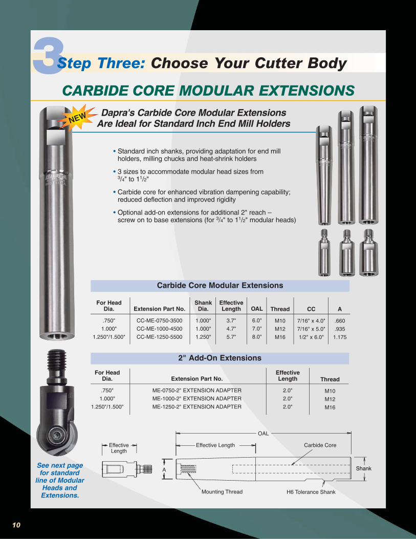
• Standard inch shanks, providing adaptation for end millholders, milling chucks and heat-shrink holders
• 3 sizes to accommodate modular head sizes from 3/4" to 11/2"
• Carbide core for enhanced vibration dampening capability;reduced deflection and improved rigidity
• Optional add-on extensions for additional 2" reach – screw on to base extensions (for 3/4" to 11/2" modular heads)
3Step Three: Choose Your Cutter Body
CARBIDE CORE MODULAR EXTENSIONSDapra's Carbide Core Modular Extensions
Are Ideal for Standard Inch End Mill Holders
See next pagefor standard
line of ModularHeads andExtensions.
For HeadDia.
.750"
1.000"
1.250"/1.500"
Extension Part No.
CC-ME-0750-3500
CC-ME-1000-4500
CC-ME-1250-5500
OAL
6.0"
7.0"
8.0"
Thread
M10
M12
M16
CC
7/16" x 4.0"
7/16" x 5.0"
1/2" x 6.0"
A
.660
.935
1.175
EffectiveLength
3.7"
4.7"
5.7"
ShankDia.
1.000"
1.000"
1.250"
For HeadDia.
.750"
1.000"
1.250"/1.500"
Extension Part No.
ME-0750-2" EXTENSION ADAPTER
ME-1000-2" EXTENSION ADAPTER
ME-1250-2" EXTENSION ADAPTER
Thread
M10
M12
M16
EffectiveLength
2.0"
2.0"
2.0"
A
Mounting Thread
Effective LengthEffectiveLength
OAL
Carbide Core
Shank
H6 Tolerance Shank
Carbide Core Modular Extensions
2" Add-On Extensions
NEW

11
3Step Three: Choose Your Cutter Body
Ball Nose Screw-On Heads
M (MOUNTING THREAD)
E
DIA
Dia.
.500"/12mm
.625"/16mm
.750"/20mm
1.000"/25mm
1.250"/32mm
Holder
GWR12-MOD
GWR16-MOD
GWR20-MOD
GWR25-MOD
GWR32-MOD
M
M8*
M8*
M10
M12
M16
E
1.05"
1.11"
1.28"
1.65"
1.78"
Flutes
2
2
2
2
2
Wrench
3/8"
7/16"
9/16"
11/16"
15/16"
Modular Extensions**
Modular Head Dia.
.750"/20mm
1.000"/25mm
1.250"/32mm
Part No.
ME-0750-18MM-900
ME-1000-25MM-1100
ME-125/150-25MM-1200
OAL
9"
11"
12"
S
18mm
25mm
25mm
M
M10
M12
M16
OAL
M(MOUNTING THREAD,
BOTH ENDS)
S(SHANK
DIAMETER)
• Compatible with ISO standard modular cutting systems• Close-tolerance mounting of heads minimizes runout and
maximizes rigidity• Provide significantly more effective reach than solid end mills• Use standard inch wrench flats, no special metric wrenches needed
• Made of high-density tungsten, providingextra resistance to deflection and chatter
• Machined on both ends; can be cut in halfand used with two different modular heads
• Metric shank diameter provides clearancefor each inch size modular head
** Using modular extensions at full length is notgenerally recommended. Use for very light cutting at significantly reduced speeds and feeds only.
Modular Extensions** Provide Even More Cutting Options
* M8 modular extensions not available. Use ISO standard bars.
SCREW-ON MODULAR HEADS & EXTENSIONSDapra's Screw-On Heads Fit Industry Standard Cutting Systems
More cutter options follow on page 12.

Spare Parts & ToolsInsert Screw
GWS 08
GWS 10
GWS 12
GWS 16
GWS 20
GWS 25
GWS 32
Insert SizeInch
.312
.375
.500
.625
.750
1.000
1.250
Metric
8
10
12
16
20
25
30/32
WrenchesTorx®
T8F
T15F
T20F
T20F
T20F
T30L
T30L
TorqueNm/in.lbs.
Manual
Manual
6.0/53
6.2/55
6.2/55
6.5/58
6.5/58
Dia.
3mm
4mm
5mm
5mm
5mm
6mm
8mm
MajorDia.
3mm
4mm
5mm
5mm
5mm
6mm
8mm
Pitch
.5mm
.5mm
.5mm
.5mm
.5mm
.75mm
.75mm
MiscellaneousDescription
Special Anti-Seize Grease
Catalog No.
ASG-120
TORX ® is a registered trademark of Camcar/Textron.
* T10 wrenches available for older-style insert screws.
NOTE: New cutter bodies may require additional torque to fully seat the inserts. Once new cutter pockets are "broken in," the recommended torque specs in the chart can be followed regularly.
T20F T15FT30L T10F*
T8F
-16 -12 -10 -08GWS-32 -25 -20
12
S
E
L
DDNS
E
L
DDN
Tapered Metric Holder Straight Metric Holder
10mm
12mm
12mm
16mm
20mm
20mm
25mm
25mm
32mm
25mm 100mm 10mm 7mm GWS 08
HolderD Ø E L S DN Insert ScrewDiameter Effective Length Overall Length Shank Diameter Neck Diameter
Tapered Solid MetricGWR08-100-10-RZK
GWR10-130-10-RZ
GWR12-150-12-RZ
SC-GWR-12-180-12MM-RZ
GWR16-180-16-RZ
SC-GWR-20-250-18MM-RZ
GWR20-230-20-RZ
GWR25-250-25-RZ
SC-GWR-25-250-25MM-RZ
GWR32-250-32-RZ
8 mm
25mm
47mm
38mm
52mm
57mm
65mm
70mm
76mm
70mm
130mm
150mm
180mm
180mm
250mm
230mm
250mm
250mm
250mm
10mm
12mm
12mm (CARBIDE)
16mm
18mm (CARBIDE)
20mm
25mm
25mm (CARBIDE)
32mm
9mm
10.5mm
10.5mm
14.5mm
17mm
18mm
22.5mm
22mm
27.5mm
GWS 10
GWS 12
GWS 12
GWS 16
GWS 18
GWS 20
GWS 25
GWS 25
GWS 32
Straight Solid Metric
METRIC STEEL
*Note: All Dapra Ball Nose end mills accept either inch or metric inserts of like sizes.Example: BNEM0750 and GWR20 accept either a 3/4" or 20mm diameter insert.
BNEM0500 and GWR12 accept either a 1/2" or 12mm diameter insert.
3Step Three: Choose Your Cutter Body

Application Information
Technical Considerations• Always use anti-seize compound on threads
and screw body.
• Thoroughly clean pocket and screw at eachinsert change.
• Change insert screw every 10 inserts.
• Use high-quality tool holders: power chucksand ER collets are recommended; end millholders are not recommended.
• Cutter bodies will wear and fatigue over time;inspect tool before each use.
Recommendations• Maximum Depth of Cut (DOC) for finishing should
be less than or equal to 10% of ball diameter.
• Stepover should be greater than or equal to DOC.
• For roughing operations, maximum recommended Width of Cut (WOC) and DOC are30% of ball diameter.
• Starting Feed per Revolution (FPR) should be 1% of ball diameter.Example: .750" diameter x .01 = .0075" FPR
• Climb milling is preferred.
• When plunging with Ball Nose, use pecking cycle with a maximum of .005"FPR; maximum recommended depth is 30% of ball diameter.
• Back Draft and Flat Bottom Inserts are not designed for plunging;ramp in at a maximum angle of 2˚.
• Compensate for Effective Cutting Diameter (see Table 1 and Fig.1 on p. 14).
• Compensate for chip thinning with Feed Rate Adjustment (see Table 2on p. 14).
• Surface finish (RMS) is a function of stepover and feed per tooth.
• Try to work within recommended surface footage and chip loads.
• Decrease feed rate coming into corners to reduce chatter.
• For long-reach applications, utilize the Carbide Shank/Carbide Core cutting tools forincreased rigidity and reduced chatter.
13
DISCLAIMER: Modern metal cutting techniques involve the potential use of very high operating parameters (speeds, feeds, depths of cut,etc.). This creates the potential for flying chips and debris, and can also create tool breakage due to a variety of causes. As such, anymetal cutting operation should be executed in a completely enclosed (shielded) environment to protect against injury from flying objects.Dapra does not assume responsibility for any loss, damage or expense incurred in any use or handling of our product after purchase.Grinding produces hazardous dust. To avoid adverse health effects, use adequate ventilation and read material safety data sheet first.This product contains a chemical known to the state of California to cause cancer.

EFFECTIVECUTTING DIA.
DEPTH OF CUT
INSERTDIAMETER
1/4"3.62.62.11.81.71.21.1
5/16"4.02.82.32.01.81.41.21.1
3/8"4.43.12.62.22.01.51.21.11.1
1/2"5.03.62.92.62.31.71.41.21.21.1
5/8"5.64.03.32.82.61.81.51.41.31.21.1
3/4"6.14.43.63.12.82.01.71.51.31.31.21.1
1"7.15.04.13.63.22.31.91.71.51.41.31.31.21.1
11/4"7.95.64.64.03.62.62.11.81.71.51.41.41.21.21.1
Table 2: Feed Rate Adjustment (FRA)Insert Diameter
.005
.010
.015
.020
.025
.050
.075
.100
.125
.150
.175
.200
.250
.300
.400
Dep
th o
f C
ut
(DO
C)
Use multiple above to calculate adjusted feed rate.
Figure 1
.005.070.086.099.111.122.141.158
.010.098.121.140.157.172.199.223
.015.119.147.171.191.210.243.272
.025.150.187.218.245.269.312.350
.035.173.218.255.287.316.368.412
.050.200.255.300.339.374.436.490
.100.245.332.400.458.510.600.678
.125.250.354.433.500.559.661.750
Table 1: Effective Cutting Diameter (ECD)Depth of Cut (DOC)
.250
.375
.500
.625
.7501.0001.250In
sert
Dia
met
er
.150
.367
.458
.534
.600
.714
.812
.200
.374
.490
.583
.663
.800
.917
.250
.500
.612
.707
.8661.000
1. Select diameter of tool to be used.2. Determine Depth of Cut (DOC) to be used.3. Refer to Figure 1 and Table 1 to find the Effective Cutting Diameter
(ECD).4. Refer to Feed and Speed chart on back cover to select the surface
footage to be used (SFM).5. Calculate RPM using the ECD and SFM. (SFM x 3.82 / ECD = RPM)6. Refer to Table 2 to determine Feed Rate Adjustment (FRA).7. Refer to chart on back cover to select Feed per Revolution (FPR).
Calculate Inches per Minute (IPM). (RPM x FPR x FRA = IPM)
*For a Ball Nose scallop height calculator, please refer to our speed and feed calculator at www.dapra.com.
14
Feed, Speed & Diameter Compensation

Troubleshooting
Concern
Insert wear at tip
Insert wear appearshigh (flank wear)
Insert chipping
Built-up edge on insert
Poor finish/chatter
Tool shank breaks
Possible Cause
• Not enough chip load
• Not enough chip load• Surface footage is high• Incorrect grade or coating
• Surface footage is low• Incorrect grade or coating• Using CB style insert incorrectly• Feed too high
• Low surface footage• Light chip load (feed per tooth)• Incorrect coating
• Cutter hung out too far• Excessive runout
• Tool pressure too great• Fatigued cutter body
Solutions
❏ Verify correct speed and feed❏ Increase feed rate❏ Decrease RPM❏ Increase DOC
❏ Verify correct speed and feed❏ Increase feed rate❏ Decrease RPM❏ Consider different insert
❏ Verify correct speed and feed❏ Increase spindle speed❏ Decrease feed rate❏ Change insert selection❏ Decrease DOC❏ Use N style insert
❏ Verify correct speed and feed❏ Increase cutting speed❏ Increase feed rate❏ Select different coating
❏ Use Carbide Core cutter body❏ Reduce tool gage length❏ Check tool holder wear
❏ Decrease DOC❏ Reduce tool gage length❏ Decrease feed rate
15
How to Apply Anti-Seizeto Ball Nose Insert Screws
1. Anti-seize must be applied before using tool for first time.
2. Remove screw from cutter body.
3. Generously apply anti-seize to entire length of screw body, not to justthe threads (see diagram).
4. Clean out insert pocket before assembly of insert/screw combination.
5. Place insert into cutter-body pocket.
6. Place screw with applied anti-seize into position in cutter body.
7. While gently pushing on the end of the TORX® screwdriver/ wrench, begin tightening the screw (mayturn with slight resistance in order to pull insert tight into the pocket).
8. Tighten screw to snug fit, taking care not to overtighten. Follow torque specifications shown above.
9. Repeat steps 2-8 for each insert change.
10. Replace screw with each new box of inserts to assure maximum performance.
Generously apply anti-seize to thesesurfaces with each insert change.

Example
1008, 1018, 12L141040, 1045, 10551060, 1070, 10954012, 4320, 4340
52100, 51208620, 8622, 8640
A2, D2, P20,W2, H13, S7
403, 416, 430, 430F, 434, 446, S44400
304L, 303, 304, 316L15-5PH, 17-4PH, custom,455, PH13-8 Mo, AM355
A48 Class xx B, A436 Type 2
A47, A220, SAE J14860-40-18, 100-70-03,
SAE J434
2024-T4, 6061-T6, 7075-T6
J463, B121, Ampco 21, Wearite 4-13
Inconel 617, Monel K500, Waspaloy, CuNi 70-30
Ti99.9, Alpha Alloy,Ti-6Al-4V
< 3%C3%-6%C5%-1.5%C
MoCr
NiCrMo
Ferritic/MartensiticAusteniticPrecipitation Hardening (PH)
Gray
Malleable
Ductile
CuNi:refer to High-Temp. Alloys below
MATERIAL GROUP
66 Granby Street, Bloomfield, CT 06002
800-243-3344 • 860-242-8539 • Fax 860-242-3017
Email [email protected] • www.dapra.com
Bringing Better Ideas to the Cutting Edge™Dapra Ball Nose finishing products are proudly made in the USA.
© Copyright 2010 Dapra Corporation 10-10-5M
Recommended Cutting Speeds
SPEEDLower Speed Ranges for: Heavier cuts, harder materials, larger diameter tools Medium Speed Ranges for: Semi-finishingHigher Speed Ranges for: Lighter cuts, softer materials, smaller diameter tools
FEEDLower Feed Ranges for: Heavier cuts, harder materials, smaller diameter toolsHigher Feed Ranges for: Lighter cuts, softer materials, larger diameter tools
The parameters provided are suggested operating parameters. Actual speeds and feeds will depend on many variables,such as rigidity, workpiece hardness, tool extension, machine accuracy, Depth of Cut, etc. Start at the middle of the SFMrange and the low end of the FPR range. Next, increase FPR to optimize productivity and tool life. Higher SFM will providehigher output but will reduce tool life. Try different combinations to find the parameters that best suit your needs.
** Best choice grades shown in bold text Refer to the Diameter and Feed Rate Adjustment chartson page 14 for accurate RPM and IPM calculations
F1(uncoated)
300-600
N/R
150-300
350-600
1000+
400-600
50-125
50-125
700-1200
FPX
400-1000
300-900
N/R
250-800
150-650
150-500
300-900
1000+
400-800
50-200
50-200
700-1500
Geometry
HBNNCB
HBN, N
HBN, N, CB
HBN,CB
HBN,N
HBN, CB
HBN, CB
HBN, CB
HBN, N,PCD
FPR
.002-.012
.003-.010
.003-.015
.005-.025
.002-.009.002-.008
.002-.015
FPO
500-1200
350-1100
N/R
300-950
180-780
180-600
360-1100
1000+
450-950
50-200
50-200
700-1500
FPA/FP-GLH
800-1600
700-1400
400-800
350-1200
300-1100
300-900
500-1200
400-1100
1000+
500-1000
100-450
150-650
1200+
PCD
N/R
N/R
N/R
N/R
N/R
N/R
N/R
N/R
2000+
N/R
N/R
N/R
1200+
PLAINSTEELS
ALLOYSTEELS
TOOL & DIE STEELS
HARDENEDSTEELS
STAINLESSSTEELS
CAST IRON
ALUMINUMALLOYS
COPPERALLOYS
HIGH-TEMP.ALLOYS
TITANIUMALLOYS
CARBONGRAPHITE