New ACI Provisions on Hooked and Headed Reinforcing...
71
New ACI Provisions on Hooked and Headed Reinforcing Bars David Darwin 69 th Annual Concrete Conference December 5, 2019
Transcript of New ACI Provisions on Hooked and Headed Reinforcing...

New ACI Provisions on Hooked and Headed Reinforcing Bars
David Darwin
69th Annual Concrete ConferenceDecember 5, 2019

OutlineACI 318-14 Provisions and Basis for Provisions Scope of StudiesWhat We’ve LearnedComparison of Test Data with ACI 318-14Design Approach in ACI 318-19Things We Need to Work On

Emphasis on high-strength reinforcing steel but full range of bar stresses studiedAnchorage of High-Strength Reinforcing Bars with Standard HooksAnchorage of High-Strength Reinforcing Bars with Heads

Sponsors

ACI 318-14 Equations
Hooks:
Heads:
ψ ψ ψ50λy e c r
dh bc
fd
f
= ′
0.016 ψy edt b
c
fd
f
= ′

Modification factorsEpoxy-coated reinforcement:
Cover*:
Confining reinforcement*:
Lightweight concrete*:
Excess reinforcement*:
* Hooks only
( )( )
required provided
s
s
AA
ψ 0.7c =
ψ 0.8r =
λ 0.75=
ψ 1.2e =
ACI 318-14

Limitations on and Head Size
Hooks:
Heads:
Abrg ≥ 4Ab
and c yf f′
10,000 psi; 80,000 psic yf f′ ≤ ≤
6,000 psi; 60,000 psic yf f′ ≤ ≤
ACI 318-14

Limitations on bar spacing
Headed bars:Cover = as required for straight barsClear spacing – horizontal layerClear spacing – vertical layers
2 bd≥ 4 bd≥ 4 bd≥
ACI 318-14

Design Equations in ACI 318-19
Hooks:
Heads: 1.5ψ ψ ψ ψ75
y e p o cdt b
c
fd
f
= ′
1.5ψ ψ ψ ψ55λ
y e r o cdh b
c
fd
f
= ′

Basis for ACI 318-14 Provisions for Hooked Bars
38 tests of standard hooked bars that failed in bond
Concrete strength = 3.8 –5.1 ksi
Yield strengths = 64 and 68 ksi

Basis for ACI Provisions for Headed Bars ~100 splice, side and shallow blowout, and CCT node testsConcrete strength ≤ 3.5 – 5.5 ksi Yield strength ≤ 69 ksiNormalweight concrete
Scope of StudiesTest SpecimensRange of Variables

Test Specimens

Beam-Column Joints

Test Apparatus

Hooked and Headed Bar Specimens
Headed BarsHooked Bars

Multiple Hook and Headed Bar Test Specimens

Slab tests – Headed Bars

CCT Node Tests – Headed Bars
eh eh

Splices – Headed Bars
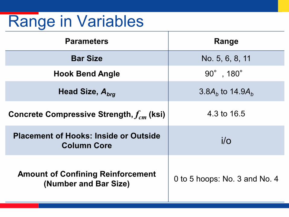
Range in VariablesParameters Range
Bar Size No. 5, 6, 8, 11
Hook Bend Angle 90°, 180°
Head Size, Abrg 3.8Ab to 14.9Ab
Concrete Compressive Strength, fcm (ksi) 4.3 to 16.5
Placement of Hooks: Inside or Outside Column Core i/o
Amount of Confining Reinforcement (Number and Bar Size) 0 to 5 hoops: No. 3 and No. 4

Range in Variables con’dParameters Range
Nominal Side Cover, cso (in.) 1.5, 2.5, 3, 3.5, 4
Nominal Tail Cover, cth (in.) 2 to 18
Nominal Embedment Length, eh (in.) 4 to 26
Number of Bars 2 to 6
Center-to-Center Spacing of Bars 2db to 11db (< 1.3db for splices)
Stress at Failure, fsu (ksi) 23 to 153

Headed Bars
Cold-Swaged Threaded Coupling Sleeve
Friction-Forged
Taper-Threaded
Cold-Swaged

What we’ve learned – 1 Hooked and headed bars behave a lot alikeFor the same embedment length, headed bars provide a higher anchorage force than hooked barsClosely spaced hooked and headed bars are weaker, individually, than widely spaced hooked and headed bars

What we’ve learned – 2 Hooked bars with 90° and 180°degree bends have similar anchorage strengthsConfining reinforcement parallel to the bar increases anchorage strength of hooked and headed barsConfining reinforcement perpendicular to the bar increases anchorage strength of hooked but not headed bars

What we’ve learned – 3 Confining reinforcement makes a bigger contribution for closely-spaced bars than for widely-spaced barsACI 318-14 did not accurately represent anchorage strength of hooked or headed bars in terms of the effect of bar size and the contributions of confining reinforcement and concrete compressive strength

Crack Progression – Hooked bars

Failure Modes
Breakout Side Splitting Tail Kickout

Comparison of Crack Patterns
Hooked bars Headed Bars

Standard Hooks

ACI 318-14 Equation (in.-lb)
ψ ψ ψ50λy e c r
dh bc
fd
f=
′
,
50λψ ψ ψ
eh cms ACI
b e c r
ff
d=

Comparison to ACI 318-14 for No Confining Reinforcement – Two-hooks
0.0
0.2
0.4
0.6
0.8
1.0
1.2
1.4
1.6
1.8
2.0
0 5 10 15 20
f su/f
s,AC
I
Concrete Compressive Strength, fcm (ksi)
No. 5 Hook
No. 6 Hook
No. 7 Hook
No. 8 Hook
No. 9 Hook
No. 11 Hook

Comparison to ACI 318-14 for No. 3 (No. 10) Ties Spaced at 3db – Two-hooks
0.0
0.2
0.4
0.6
0.8
1.0
1.2
1.4
1.6
1.8
2.0
0 5 10 15 20
f su/f
s,AC
I
Concrete Compressive Strength, fcm (ksi)
No. 5 Hook
No. 6 Hook
No. 8 Hook
No. 7 Hook
No. 11 Hook

Confining Reinforcement Orientation
After ACI 318-14


Confining Reinforcement Orientation
Hooked Bar
Parallel Hoop
Hooked Bar
Perpendicular Hoop

Descriptive Equation
1.020.295 1.085 0.47 0.73294 55,000 th
h b s cm eh b bAT A f f d dn
= = +
Two widely-spaced hooked bars with confining
Ath = total area of confining steel n = number of hooked bars

Closely spaced and staggered hooked bars

Hooked bars without confining reinforcement
y = 0.0907x + 0.4175
0.0
0.2
0.4
0.6
0.8
1.0
1.2
1.4
1.6
0 2 4 6 8 10 12 14
Test
/Cal
cula
ted,
T/T
c
Spacing/db
Hooks ≥ 6 db
No. 5 ≤ 6 db
No. 7 ≤ 6 db
No. 8 ≤ 6 db
No. 11 ≤ 6 db

Hooked bars with confining reinforcement
y = 0.0357x + 0.7402
0.0
0.2
0.4
0.6
0.8
1.0
1.2
1.4
1.6
0 2 4 6 8 10 12 14
Test
/Cal
cula
ted,
T/T
h
Spacing/db
Hooks ≥ 6 db
No. 5 ≤ 6 db
No. 8 ≤ 6 db
No. 11 ≤ 6 db

Hook placement within member
Insidecolumn core
Outsidecolumn core

Ratio Toutside to Tinside
0
0.2
0.4
0.6
0.8
1
1.2
0 5 10 15
T out
side
/Tin
side
fcm (ksi)
No. 8, 0TR
No. 8, 5#3
No. 11, 0TR
No. 11, 6#3

Reinforcing Bars with Heads
obstruction not considered to detract from the net bearing area of the head.
largest obstruction permitted

Comparison to ACI 318-14
0.016 ψy edt b
c
fd
f
= ′
,
62.5ψ
eh cms ACI
e b
ff
d=

Comparison to ACI for Two-Head Specimens with No Confining Reinforcement
0
0.5
1
1.5
2
2.5
3
3.5
4
0 5 10 15 20
f su/f
s,AC
I
Concrete Compressive Strength, fcm (ksi)
No. 5, 13AbNo. 5, 4AbNo. 8, 15AbNo. 8, 4AbNo. 8, 9AbNo. 8, 6AbNo. 11, 6AbNo. 11, 4AbNo. 11, 9AbNo. 5, 13AbNo. 5, 4AbNo. 8, 15AbNo. 8, 4AbNo. 8, 9AbNo. 8, 6AbNo. 11, 6AbNo. 11, 4AbNo. 11, 9Ab

Comparison to ACI for Two-Head Specimens with No. 3 Ties Spaced at 3db
0
0.5
1
1.5
2
2.5
3
3.5
4
0 5 10 15 20
f su/f
s,AC
I
Concrete Compressive Strength, fcm (ksi)
No. 5, 13AbNo. 5, 4AbNo. 8, 9AbNo. 8, 15AbNo. 8, 4AbNo. 8, 6AbNo. 11, 6AbNo. 11, 4AbNo. 11, 9AbNo. 5, 13AbNo. 5, 4AbNo. 8, 9AbNo. 8, 15AbNo. 8, 4AbNo. 8, 6AbNo. 11, 6AbNo. 11, 4AbNo. 11, 9Ab

Descriptive Equation
0.24 1.03 0.35 0.88781 48,800 tth b s cm eh b b
AT A f f d dn
= = +
For two widely spaced headed bars with confining reinforcement oriented parallel to the bar:

Headed Bar Specimens with more than two headed bars

Headed Bars with No Confining Reinforcement
y = 0.0835x + 0.3433
0
0.2
0.4
0.6
0.8
1
1.2
1.4
0 2 4 6 8 10 12 14
T/T
c
Center-to-center Spacing/db
No. 5No. 8No. 11widely spaced

Headed Bars with Confining Reinforcement
y = 0.0622x + 0.5428
0
0.2
0.4
0.6
0.8
1
1.2
1.4
0 2 4 6 8 10 12 14
T/T
h
Center-to-center Spacing /db
No. 5No. 8No. 11widely spaced

Design Approach – Initial ProposalConvert descriptive equations (without confining reinforcement, hooked bar spacing > 6db, headed bar spacing > 8db) to equations for development length dh, dt
Then account for1. closer bar spacing2. confining reinforcement3. bar location within the member
Incorporate a reliability-based φ-factor

Design Equations – Initial Proposal (in.-lb)
1.50.25
ψ ψ ψ500λ
y e cs odh b
c
fd
f
= ′
1.50.25
ψ ψ ψ800
y e cs odt b
c
fd
f
= ′
Applicable for up to 16 ksicf ′

Design Equations – Initial Proposal
ψ coating factorψ confinement and spacing factorψ location factorλ = concrete density (hooks only)
e
cs
o
===

Confinement based on:Ath/Ahs, Att/Ahs
whereAth, Att = total cross-sectional area of ties or stirrups confining hooked or headed bars Ahs = total cross-sectional area of hooked or headed bars developed at critical section

Region for confining reinforcement Ath parallel to straight portion of hooked bar

Region for confining reinforcement Athperpendicular to straight portion of hooked bar

Region for confining reinforcement Attparallel to headed bar

Bar location factor ψo
Bars within a column core with side cover ≥ 2.5 in. or in a wall with side cover ≥ 6db: ψo = 1.0
Otherwise: ψo = 1.25
Toutside ~ 0.80 Tinside

Comparison with test resultsFor hooked bars without confining reinforcement
0
0.2
0.4
0.6
0.8
1
1.2
1.4
1.6
1.8
2
0 5 10 15 20
Test
/Cal
cula
ted,
f su/f
s,ca
lc
Concrete Compressive Strength, fcm (ksi)
No. 11
No. 7
No. 8
No. 5
No. 6
No. 11
No. 7
No. 8
No. 5
No. 6
widely spaced

Comparison with test resultsFor hooked bars with confining reinforcement
0
0.2
0.4
0.6
0.8
1
1.2
1.4
1.6
1.8
2
0 5 10 15 20
Test
/Cal
cula
ted,
f su/f
s,ca
lc
Concrete Compressive Strength, fcm (ksi)
No. 11
No. 8
No. 5
No. 11
No. 8
No. 5
widely spaced

ACI 318-19Stay with but modify equation to represent the effect of compressive strength based on for compressive strengths < 6000 psiLimit maximum to 10,000 psi for use in calculating dh and dt
Simplify representation of confining reinforcement and bar spacing
cf ′
0.25cf ′
cf ′

ACI 318-19 (in.-lb) Hooked Bars
1.5ψ ψ ψ ψ55λ
y e r o cdh b
c
fd
f
= ′
ψ coating factorψ confining reinforcement factorψ location factorψ concrete strength factorλ = concrete density
e
r
o
c
====

ACI 318-19 (in.-lb) Headed Bars
1.5ψ ψ ψ ψ75
y e p o cdt b
c
fd
f
= ′
ψ coating factorψ parallel tie reinforcement factorψ location factorψ concrete strength factor
e
p
o
c
==
==

ACI 318-19 Confinement and Spacing No. 11 (No. 36) and smaller bars
Modification Factor
Condition Value
Hookedbars
Confining Reinforcement
ψr
Ath ≥ 0.4Ahs or s ≥ 6db 1.0
Other 1.6
Headedbars
Parallel tiereinforcement
ψp
Att ≥ 0.3Ahs or s ≥ 6db 1.0
Other 1.6

ACI 318-19 Location FactorNo. 11 (No. 36) and smaller bars
Modification Factor
Condition Value
Hookedbars
Location
ψo
(1) Terminating inside columncore with side cover normal to
plane of hook ≥ 2.5 in. (65 mm), or
(2) With side cover normal toplane of hook ≥ 6db
1.0
Other 1.25
Headedbars
Location
ψo
(1) Terminating inside columncore with side cover ≥ 2.5 in. (65
mm), or(2) With side cover ≥ 6db
1.0
Other 1.25

ACI 318-19 Concrete Strength Factor
Modification Factor
Condition Value
Hooked & Headed
Bars
Concrete strength
ψc
< 6000 psi /15,000 + 0.6
> 6000 psi 1.0cf ′
cf ′ cf ′

Drop Excess Reinforcement Factor for Hooks
( ) ( ), ,s required s providedA A
because T is proportional to 1.085eh

Things we need to work on
Hooked and headed bars larger than No. 11 Seismic provisions for hooked barsAdd more detailed expressions to allow designers to take advantage of confining reinforcement Ath < 0.4Ahs or Att < 0.3Ahsfor bar spacing s less than 6db


The University of Kansas
David Darwin, Ph.D., P.E.
Deane E. Ackers Distinguished Professor and Chair
Dept. of Civil, Environmental & Architectural Engineering
2150 Learned Hall
Lawrence, Kansas, 66045-7609
785 864-3827 Fax: 785 864-5631