Neutralization of explosives by plasma jet impingement: feasibility study
11
312 IEEE TRANSACTIONS ON PLASMA SCIENCE, VOL. 28, NO. 1, FEBRUARY 2000 Neutralization of Explosives by Plasma Jet Impingement: Feasibility Study Jong-Uk Kim, Kyoungjin Kim, Dennis E. Wilson, Dennis R. Peterson, and Noel T. Clemens Abstract—Preliminary results of an experimental study to de- termine the feasibility of neutralizing explosives by impingement of a high-temperature, high-velocity pulsed plasma jet are pre- sented. The pulsed plasma jet was created by an electrothermal gun, a device that relies upon vaporization of solid metal to pro- duce a metal vapor plasma. The tests were conducted using an alu- minum plasma with a pulse duration of 1 ms and peak energy of 100 kJ on 1-g specimens of PETN explosive. The specimens were placed inside a chamber at standoff distances of 15–30 cm from the 6.65-mm diameter muzzle of the electrothermal gun. The effec- tiveness of the plasma impingement was determined by comparing postdetonation experiments on the exposed and unexposed explo- sive specimens. High-speed imaging of the plasma jet impinging on the explosive and postmortem examination of the explosive speci- mens suggests that three distinct interactions occur. These inter- actions are: slow thermal decomposition (burning); rapid thermal decomposition (deflagration); and change in chemistry with negli- gible or no thermal decomposition. Initial results suggest that these three distinct interactions are a function of the mass flow rate and energy of the plasma. Index Terms—Electrothermal gun, explosive neutralization, plasma jet. I. INTRODUCTION A. Motivation M ETHODS of neutralizing explosives, or in general unex- ploded ordnance (UXO), fall into two broad categories. The first and most common is sympathetic detonation (higher order mode). Examples are explosives, rollers, projectile attack, or shaped charge attack [1]. Although these techniques work well for military operations, they have very limited application for civilian operations such as landmine clearance or neutral- ization of terrorist devices. For example, sympathetic detona- tion is too expensive and destructive for landmine clearance on any significant area, and the resulting collateral damage in highly populated areas for terrorist devices is usually unaccept- able. The preferred alternative for civilian operation is either re- moval followed by off-site demolition or on-site neutralization by burning (i.e., lower order mode). Concepts for burning explo- sives that have been either field or laboratory tested include ther- Manuscript received July 26, 1999; revised November 16, 1999. This work was supported by the Office of Naval Research through the Applied Research Laboratories, The University of Texas at Austin. J.-U. Kim and N. T. Clemens are with the Department of Aerospace Engi- neering and Engineering Mechanics, The University of Texas at Austin, Austin, TX 78712 USA. K. Kim and D. E. Wilson are with the Department of Mechanical Engineering, The University of Texas at Austin, Austin, TX 78712 USA. D. R. Peterson is with the Applied Research Laboratories, The University of Texas at Austin, Austin, TX 78712 USA. Publisher Item Identifier S 0093-3813(00)01486-7. mite grenades, reacting projectile attack, or directed energy [1]. This last category is emerging as an effective, high-technology option and includes both high-power laser and microwave radia- tion. The primary disadvantage of this system has been the high cost and limited effectiveness against UXO with high-thermal conductivity bodies. Until recently, the research and develop- ment for neutralizing UXO has been driven by the mine clear- ance/neutralization and countermeasures community [2]. This still remains a central focus; however, a major growth industry is emerging with the broader objective of removal or on-site neu- tralization of UXO, of which mines are but one category. An ideal explosive (UXO) neutralization system should: a) produce a safe and reliable combustion of the explosive (i.e., burning or slow deflagration, not detonation); b) work on any explosive mixture (for example, there are at least 14 different explosives currently used in landmines) [2]; c) work on any munition case; d) be cost effective. One problem is that the main explosive charge is specifically designed to be shock detonated. It is difficult to burn explosives by conventional thermal sources such as combustion or radiation from lasers. A basic problem is that when the thermal source is removed, the energy release in the explosive is insufficient to sustain burning and rapid quenching results. B. Background The idea for using a high-energy thermal plasma to “burn” an explosive evolved from our work on a separate and independent study on ignition of propellants by a capillary plasma source [3]–[6]. Capillary plasma igniters (ablation-stabilized plasma sources with a suitable hydrocarbon liner, usually polyethylene) are being studied as an alternative to conventional igniters for gun propellants. The capillary plasma igniter uses both electrical and chemical energy for ignition and controlled combustion of the propellant, and the technology is referred to as electrothermal–chemical (ETC) gun propulsion. The current understanding of the rather complex phenomena is that a plasma source can be a more effective igniter because the plasma produces both an intense radiation heat flux and an abundance of energetic free radicals [7]–[10]. Relatively low energy (order of 10 kJ) plasma igniters have been used to initiate and control the burn rate of propellants [11]–[15]. Since propellants and explosives have similar fundamental chemical composition (in fact, RDX is used as both a propel- lant and an explosive), there was sufficient reason to believe that a plasma jet may be a more effective device than conven- tional thermal sources for safely burning explosives. However, 0093–3813/00$10.00 © 2000 IEEE
Transcript of Neutralization of explosives by plasma jet impingement: feasibility study

312 IEEE TRANSACTIONS ON PLASMA SCIENCE, VOL. 28, NO. 1, FEBRUARY 2000
Neutralization of Explosives by Plasma JetImpingement: Feasibility Study
Jong-Uk Kim, Kyoungjin Kim, Dennis E. Wilson, Dennis R. Peterson, and Noel T. Clemens
Abstract—Preliminary results of an experimental study to de-termine the feasibility of neutralizing explosives by impingementof a high-temperature, high-velocity pulsed plasma jet are pre-sented. The pulsed plasma jet was created by an electrothermalgun, a device that relies upon vaporization of solid metal to pro-duce a metal vapor plasma. The tests were conducted using an alu-minum plasma with a pulse duration of 1 ms and peak energy of100 kJ on 1-g specimens of PETN explosive. The specimens wereplaced inside a chamber at standoff distances of 15–30 cm fromthe 6.65-mm diameter muzzle of the electrothermal gun. The effec-tiveness of the plasma impingement was determined by comparingpostdetonation experiments on the exposed and unexposed explo-sive specimens. High-speed imaging of the plasma jet impinging onthe explosive and postmortem examination of the explosive speci-mens suggests that three distinct interactions occur. These inter-actions are: slow thermal decomposition (burning); rapid thermaldecomposition (deflagration); and change in chemistry with negli-gible or no thermal decomposition. Initial results suggest that thesethree distinct interactions are a function of the mass flow rate andenergy of the plasma.
Index Terms—Electrothermal gun, explosive neutralization,plasma jet.
I. INTRODUCTION
A. Motivation
M ETHODS of neutralizing explosives, or in general unex-ploded ordnance (UXO), fall into two broad categories.
The first and most common is sympathetic detonation (higherorder mode). Examples are explosives, rollers, projectile attack,or shaped charge attack [1]. Although these techniques workwell for military operations, they have very limited applicationfor civilian operations such as landmine clearance or neutral-ization of terrorist devices. For example, sympathetic detona-tion is too expensive and destructive for landmine clearanceon any significant area, and the resulting collateral damage inhighly populated areas for terrorist devices is usually unaccept-able. The preferred alternative for civilian operation is either re-moval followed by off-site demolition or on-site neutralizationby burning (i.e., lower order mode). Concepts for burning explo-sives that have been either field or laboratory tested include ther-
Manuscript received July 26, 1999; revised November 16, 1999. This workwas supported by the Office of Naval Research through the Applied ResearchLaboratories, The University of Texas at Austin.
J.-U. Kim and N. T. Clemens are with the Department of Aerospace Engi-neering and Engineering Mechanics, The University of Texas at Austin, Austin,TX 78712 USA.
K. Kim and D. E. Wilson are with the Department of Mechanical Engineering,The University of Texas at Austin, Austin, TX 78712 USA.
D. R. Peterson is with the Applied Research Laboratories, The University ofTexas at Austin, Austin, TX 78712 USA.
Publisher Item Identifier S 0093-3813(00)01486-7.
mite grenades, reacting projectile attack, or directed energy [1].This last category is emerging as an effective, high-technologyoption and includes both high-power laser and microwave radia-tion. The primary disadvantage of this system has been the highcost and limited effectiveness against UXO with high-thermalconductivity bodies. Until recently, the research and develop-ment for neutralizing UXO has been driven by the mine clear-ance/neutralization and countermeasures community [2]. Thisstill remains a central focus; however, a major growth industryis emerging with the broader objective of removal or on-site neu-tralization of UXO, of which mines are but one category.
An ideal explosive (UXO) neutralization system should:
a) produce a safe and reliable combustion of the explosive(i.e., burning or slow deflagration, not detonation);
b) work on any explosive mixture (for example, there are atleast 14 different explosives currently used in landmines)[2];
c) work on any munition case;d) be cost effective.
One problem is that the main explosive charge is specificallydesigned to be shock detonated. It is difficult to burn explosivesby conventional thermal sources such as combustion or radiationfrom lasers. A basic problem is that when the thermal source isremoved, the energy release in the explosive is insufficient tosustain burning and rapid quenching results.
B. Background
The idea for using a high-energy thermal plasma to “burn” anexplosive evolved from our work on a separate and independentstudy on ignition of propellants by a capillary plasma source[3]–[6]. Capillary plasma igniters (ablation-stabilized plasmasources with a suitable hydrocarbon liner, usually polyethylene)are being studied as an alternative to conventional ignitersfor gun propellants. The capillary plasma igniter uses bothelectrical and chemical energy for ignition and controlledcombustion of the propellant, and the technology is referredto as electrothermal–chemical (ETC) gun propulsion. Thecurrent understanding of the rather complex phenomena isthat a plasma source can be a more effective igniter becausethe plasma produces both an intense radiation heat flux andan abundance of energetic free radicals [7]–[10]. Relativelylow energy (order of 10 kJ) plasma igniters have been used toinitiate and control the burn rate of propellants [11]–[15].
Since propellants and explosives have similar fundamentalchemical composition (in fact, RDX is used as both a propel-lant and an explosive), there was sufficient reason to believethat a plasma jet may be a more effective device than conven-tional thermal sources for safely burning explosives. However,
0093–3813/00$10.00 © 2000 IEEE
KIM et al.: NEUTRALIZATION OF EXPLOSIVES BY PLASMA JET IMPINGEMENT 313
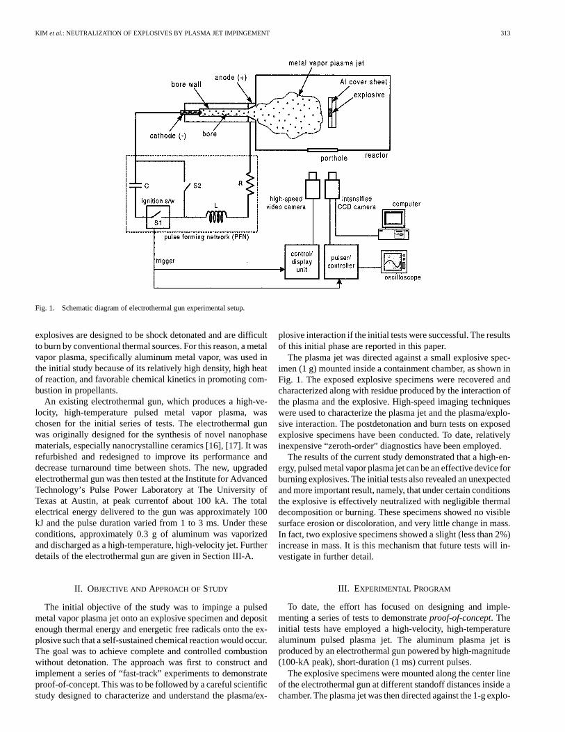
Fig. 1. Schematic diagram of electrothermal gun experimental setup.
explosives are designed to be shock detonated and are difficultto burn by conventional thermal sources. For this reason, a metalvapor plasma, specifically aluminum metal vapor, was used inthe initial study because of its relatively high density, high heatof reaction, and favorable chemical kinetics in promoting com-bustion in propellants.
An existing electrothermal gun, which produces a high-ve-locity, high-temperature pulsed metal vapor plasma, waschosen for the initial series of tests. The electrothermal gunwas originally designed for the synthesis of novel nanophasematerials, especially nanocrystalline ceramics [16], [17]. It wasrefurbished and redesigned to improve its performance anddecrease turnaround time between shots. The new, upgradedelectrothermal gun was then tested at the Institute for AdvancedTechnology’s Pulse Power Laboratory at The University ofTexas at Austin, at peak currentof about 100 kA. The totalelectrical energy delivered to the gun was approximately 100kJ and the pulse duration varied from 1 to 3 ms. Under theseconditions, approximately 0.3 g of aluminum was vaporizedand discharged as a high-temperature, high-velocity jet. Furtherdetails of the electrothermal gun are given in Section III-A.
II. OBJECTIVE AND APPROACH OFSTUDY
The initial objective of the study was to impinge a pulsedmetal vapor plasma jet onto an explosive specimen and depositenough thermal energy and energetic free radicals onto the ex-plosive such that a self-sustained chemical reaction would occur.The goal was to achieve complete and controlled combustionwithout detonation. The approach was first to construct andimplement a series of “fast-track” experiments to demonstrateproof-of-concept. This was to be followed by a careful scientificstudy designed to characterize and understand the plasma/ex-
plosive interaction if the initial tests were successful. The resultsof this initial phase are reported in this paper.
The plasma jet was directed against a small explosive spec-imen (1 g) mounted inside a containment chamber, as shown inFig. 1. The exposed explosive specimens were recovered andcharacterized along with residue produced by the interaction ofthe plasma and the explosive. High-speed imaging techniqueswere used to characterize the plasma jet and the plasma/explo-sive interaction. The postdetonation and burn tests on exposedexplosive specimens have been conducted. To date, relativelyinexpensive “zeroth-order” diagnostics have been employed.
The results of the current study demonstrated that a high-en-ergy, pulsed metal vapor plasma jet can be an effective device forburning explosives. The initial tests also revealed an unexpectedand more important result, namely, that under certain conditionsthe explosive is effectively neutralized with negligible thermaldecomposition or burning. These specimens showed no visiblesurface erosion or discoloration, and very little change in mass.In fact, two explosive specimens showed a slight (less than 2%)increase in mass. It is this mechanism that future tests will in-vestigate in further detail.
III. EXPERIMENTAL PROGRAM
To date, the effort has focused on designing and imple-menting a series of tests to demonstrateproof-of-concept. Theinitial tests have employed a high-velocity, high-temperaturealuminum pulsed plasma jet. The aluminum plasma jet isproduced by an electrothermal gun powered by high-magnitude(100-kA peak), short-duration (1 ms) current pulses.
The explosive specimens were mounted along the center lineof the electrothermal gun at different standoff distances inside achamber. The plasma jet was then directed against the 1-g explo-
314 IEEE TRANSACTIONS ON PLASMA SCIENCE, VOL. 28, NO. 1, FEBRUARY 2000
sive specimen. A total of 13 explosive specimens were exposedto the plasma jet at energy levels of 44–101 kJ and standoff dis-tances of 15–30 cm.
The explosive specimens were DuPont Detasheet C, whichconsists of 63% PETN, 8% NC plus a plasticizer. The Detasheetwas mounted on a 12.7-cm-square and 1-mm-thick aluminumsheet with Duco cement. The explosive specimen was 2.54 cmsquare and 1.0 mm thick and weighed 1 g. The explosive wasattached to the center of the aluminum sheet and mounted insidethe reactor so that its surface was perpendicular to the directionof the plasma discharge, and along the axis of the electrothermalgun exit bore. The samples were mounted on a rigid supportinside the reactor and then exposed to the electrothermal plasmajet with varying electrical energy and standoff distances.
High-speed imaging techniques were used to characterize theplasma jet and the plasma/explosive interaction. Postdetonationtests on five exposed explosive specimens have been conducted.Photomicrographs of the exposed explosive specimens and inertsurface have been made and compared to the unexposed explo-sive. To date, only these relatively inexpensive, zeroth-order di-agnostics have been used to demonstrate the feasibility of neu-tralizing an explosive with a pulsed aluminum plasma jet.
A. Electrothermal Gun
The initial phase of the study used an electrothermal gun toproduce a high-energy metal vapor plasma. The electrothermalgun is a new high-power pulsed device for producing vapors ofdifferent metals [16], [17]. The metal vapor plasma can be usedin the synthesis of novel materials, especially nanocrystallineceramics. The process employs electrode erosion to vaporizeone of the discharging electrodes. The eroded metal vapor issubsequently ionized to form a dense plasma through whicha high current discharge is sustained. The vapor plasma thenexits the muzzle to form a high-velocity, high-temperature, andhighly ionized pulsed jet. The electrothermal gun was refur-bished and modified so that it could be used to investigate thecontrolled combustion of explosives.
A schematic diagram of the experimental arrangement thatshows the electrothermal gun, chamber, and power supply isshown in Fig. 1. The electrothermal gun was driven by a pulse-forming network (PFN), which consisted of two 1.2–9.7-mF ca-pacitor banks (denoted by) in the figure, and two variable (17mH maximum) inductors (denoted by), resistors (denoted by
), and an ignition switch box. Both the capacitor and inductorcan be varied to apply a wide variety of current, energy, voltages,and pulse widths. The maximum test voltage from the capacitorbank is 11 kV, and the maximum output current is 500 kA. Themaximum energy stored in the capacitor bank is approximately1.2 MJ.
The bore of the electrothermal gun is 6.65 mm in diameterand 13.5 mm long, and is open at one end only. An aluminumelectrode is used for the metal vapor, and an aluminum fuse wireis used to initiate the discharge. When the ignition switch (S1) isclosed, the discharge of the capacitor banks is initiated, whichresults in a rapid discharge of current into the aluminum fusewire. The subsequent exploding wire fills the barrel of the elec-trothermal gun with an aluminum plasma. The primary plasmadischarge is then initiated, and the aluminum cathode is explo-
sively vaporized. The resulting plasma jet rapidly expands froman open end of the bore into the reactor. Calculations, basedupon a quasi-steady, one-dimensional model, indicate that thepeak velocity and temperature at the exit are 6 km/s and 45 000K, respectively [18].
For the present study, the peak current, charging voltage, anddischarge energy were approximately 100 kA, 5 kV, and 100 kJ,respectively, which is near the peak operating conditions for theelectrothermal gun. The time of fuse wire explosion is approxi-mately 40 s from the initiation of the pulse, and the entire dis-charge of the plasma jet is completed within 1 ms. The voltageacross the capillary, which typically peaks at 1–2 kV, was mea-sured, and plasma impedance was obtained during the entiredischarge of the plasma jet. The amount of aluminum erosionwas also measured by weighing the cathode before and aftereach shot. Typical operating conditions produce mass erosionof 0.1–0.5 g. The bore is made of an alumina ceramic that is de-signed to resist erosion [16].
B. Flowfield Visualization
Images of the visible emission were obtained by imagingthrough a 14.6-cm-diameter porthole located on the side of thechamber (shown in Fig. 1), 33 cm downstream of the gun nozzle.The chamber contained air at atmospheric pressure. The instan-taneous images, described below, were made of the plasma jetemission without an explosive specimen. The second set of im-ages was made of the plasma impingement on explosive speci-mens and an aluminum plate.
1) Instantaneous Images:The visible emission results fromthermally excited atoms, molecules, ions, and possibly black-body radiation from hot particles. These measurements weremade prior to the current set of experiments but were unreporteduntil now. They are included in this paper since they help to ex-plain the current results. They were made using an image inten-sified charge-coupled device (CCD) camera (Princeton Instru-ments ICCD-576) fitted with a 70–210-mm focal-length zoomlens operated at f/22. Since the lens did not transmit in the ultra-violet, the images were restricted to visible emission only. Thecamera was controlled by a 486 PC and was triggered at the de-sired time by delaying from the main trigger signal used to firethe capacitors. The gate width (exposure time) was 1s, whichis sufficient to freeze the motion of the flow. A fast photodiodewas used to determine the appropriate time to take an image(i.e., the time at which the plasma luminosity first reached theporthole through which the measurements were made). Threeimages of the plasma jet were obtained at different time delaysfrom the beginning of the current pulse. The time delays were400 s, 450 s, and 10 ms.
2) High-Speed Video Imaging:The temporal evolution ofthe plasma jet was investigated using a high-speed video camerasystem (redlake Motion Scope HR2000) to capture visible emis-sion from the plasma jet/explosive interaction inside the reactor.The location is shown in Fig. 1. The video images of the plasmajet were obtained through the optically accessible window de-scribed above. The recording frame rate of the video camerawas set to 2000 frames per second; therefore, the temporal res-olution of interframe image was 500s. The electronic shutteroperated at a factor of 1/20 of the set recording rates; thus the ex-
KIM et al.: NEUTRALIZATION OF EXPLOSIVES BY PLASMA JET IMPINGEMENT 315
(a)
(b)
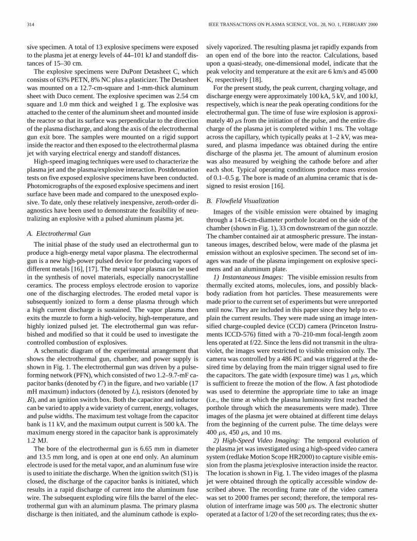
Fig. 2. (a) Schematic description of the detonation test of explosives. p1 andp2 represent the projectiles before and after the detonation, and x1 and x2 arethe projectile locations before and after detonation. (b) Detailed schematic ofthe explosive sample and detonator, which are loaded between the rigid tampand projectile.
posure time was 25s. The high-speed video camera was syn-chronized to the ignition switch of the electrothermal gun, asshown in Fig. 1. Upon receiving the trigger signal from the ig-nition switch, the high-speed video camera recorded the eventsfor 4 s before and after the shot, and saved the recorded imagesin its local memory buffer for further analysis.
C. Postimpingement Tests
1) Detonation Experiments:To quantify the effect of theplasma jet on the subsequent energy release from the explosivespecimens, a simple device was constructed as shown in Fig. 2.The projectile and tamp were cylindrical shapes with a mass of10 kg. The projectile was covered with Teflon to reduce the fric-tion between the projectile and the rail. The length of the rail was3.4 m, and the angle of inclination of the rail was approximately18 from the ground. Numbers were marked along the rail toaid in the measurements of the distance the projectile movedafter detonation. The explosive samples were loaded betweenthe rigid tamp and the projectile. An exploding bridge wire det-onator RP-80 was attached to the explosive through the hole pro-vided in the center of the tamp, as illustrated in Fig. 2(b). Ducocement was applied between the detonator and the explosive.The tamp was rigidly fixed to avoid movement when detonationoccurred. The movement of the projectile was recorded with ahigh-speed video camera, and the maximum displacement fromthe rest position was obtained by digitizing the recorded image.It should be noted that only relative comparison of the explosiveenergy is possible with this rather simple configuration.
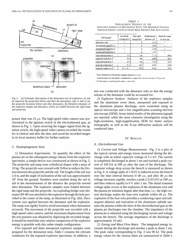
Five exposed and three unexposed explosive samples wereprepared for the detonation tests. Table I contains the relevantconditions for the exposed explosive specimens. In addition, a
TABLE IDISPLACEMENT DISTANCE OF THE
EXPLOSIVE SAMPLES IN DETONATION TESTS. THE MAXIMUM VOLTAGE,IMPINGED ENERGY AND ELECTRODEMASS EROSIONARE ALSO LISTED
test was conducted with the detonator only so that the energyrelease of the detonator could be accounted for.
2) Explosive Surface:Surfaces of the explosive samplesand the aluminum cover sheet, unexposed and exposed tothe aluminum plasma discharge, were examined using anoptical microscope and a low magnification scanning electronmicroscope (SEM). Some initial results of the photomicrographare reported, while the more extensive investigation using thehigh-resolution, high-magnification SEM for better surfacetomography as well as the X-ray diffraction analysis will beconducted later.
IV. RESULTS
A. Electrothermal Gun
1) Current and Voltage Measurements:Fig. 3 is a plot ofthe typical current and energy traces measured during the dis-charge with an initial capacitor voltage of 5.1 kV. The currentis completely discharged in about 1 ms and reached a peak cur-rent of 100 kA at 500 s after the start of the discharge. Thetransient voltage drop across the breech is measured as shownin Fig. 4. A voltage spike of 1.8 kV is induced across the breechover the time interval between 0–40s, and after 40 s thevoltage increases rapidly, reaches a peak (∼1.65 kV) at 500 s,and then reduces rapidly to 0 V after 1 ms. The initial transientvoltage spike occurs at the explosion of the aluminum wire andthe plasma jet initiation begins after that time, i.e., the high cur-rent discharge makes the fuse-wire explode within 40s. Theexplosion of the fuse wire provides a conducting vapor and sub-sequent ablation and ionization of the aluminum cathode sus-tains the plasma within the bore of the electrothermal gun as theplasma jet discharges into the chamber. The impedance of theplasma jet is obtained using the discharging current and voltageacross the breech. The average impedance of the discharge isapproximately 10 m.
2) Energy and Mass Flow Rates:The integrated energy in-creases during the discharge and reaches a peak at about 1 ms.The peak value corresponding to Fig. 3 was 96 kJ. The peakenergy values for the various shots are summarized in Table I.

316 IEEE TRANSACTIONS ON PLASMA SCIENCE, VOL. 28, NO. 1, FEBRUARY 2000
Fig. 3. Typical current and energy traces obtained during the discharge of theplasma jet with an initial capacitor charging voltage of 5.1 kV.
Fig. 4. The transient voltage drop across the breech in the electrothermal gun.
The mass eroded during each shot was estimated by weighingthe aluminum cathode before and after each shot. The bore wallerosion of the alumina bore was assumed to be negligible. Theresults for the cathode mass erosion are summarized in Table I.
It should be emphasized that because the specimen is locatedat a nondimensional distance ( ) of 22.5 to 45 from themuzzle, the energy and mass deposited on the target are con-siderably less than the energy released from the electrothermalgun. An estimate was made of the “effective” energy and massdeposited on each target using results from reference [18]. Theeffective energy varies from 2.5% at a standoff distance of 15cm ( ) to 1.5% at 30 cm ( ). The majorityof the shots used a nominal energy of 100 kJ; thus the energy onthe target varied from 2.5 to 1.5 kJ. By comparison, the energycontent of the explosive specimen is approximately 4 kJ.
Fig. 5. Instantaneous image of plasma jet by intensified CCD camera at 400�s.
B. Visualization of the Plasma and Explosive
Qualitative information was obtained from the instantaneousimages of the plasma flow field acquired without an explosive(which we refer to as baseline measurements) and high-speedvideo images of the plasma interaction with an explosive and aninert specimen. The results are presented below and provide apossible interpretation of the plasma/explosive interaction.
1) Instantaneous Images of the Plasma:Fig. 5 shows animage of the freely expanding plasma jet for the baseline ex-periment, i.e., without an explosive specimen, at a time delay of400 s. The front of the plasma jet is about two-thirds of the wayacross the porthole. The surface of the plasma is quite detailedand even appears as if it is a solid surface. The solid surfaceappearance is an indication that the plasma is optically thick atvisible wavelengths. This means that emitted visible light is re-absorbed over a very short distance. An optically thin plasmawould appear much more diffuse, without a distinct surface.
In Fig. 6, the plasma is shown at a time delay of 450 or 50s later than in Fig. 5. The front of the plasma jet has moved
across nearly the entire field of view. If it is assumed that theplasma is repeatable from shot-to-shot, then a velocity can becalculated from the distance it has traveled. The calculated ve-locity is 620 m/s, which is in excellent agreement with the valueinferred from the photodiode signal. This is perhaps fortuitoussince other shots have indicated that the location of the plasmais repeatable to within only about ±10s, resulting in a velocityuncertainty of about ±20%.
Fig. 7 shows the visible emission 10 ms after the beginningof the current pulse or 9 ms after the current flow has ceased. Atthis time delay, the signal levels are reduced by about 800 timesover those of Figs. 5 and 6. Apparent in the figure is that theflow is now composed of particles. These particles are still hotat this time, since no visible radiation would be expected fromroom-temperature particles. The time scale for the pulsed jet isapproximately 1 ms. The suspended nanophase particles cool,primarily by radiation and convection. The photodiode trace,which accompanied these images but is not shown, reveals a

KIM et al.: NEUTRALIZATION OF EXPLOSIVES BY PLASMA JET IMPINGEMENT 317
Fig. 6. Instantaneous image of plasma jet by intensified CCD camera at 450�s.
Fig. 7. Instantaneous image of plasma jet by intensified CCD camera at 10 ms.
peak emission at approximately 1 ms followed by a second smallpeak at approximately 5 ms. The second peak is most likelythe result of the aluminum reaction with atmospheric pressureair in the reaction chamber forming nanocrystalline aluminumnitride and alumina. Experimental results using SEM and X-raydiffraction from [16] for the plasma jet fired into the reactionchamber containing only atmospheric air confirm the presenceof nanophase aluminum nitride and alumina particles.
These images for the baseline flowfield can be used to infer asequence of events for the pulsed plasma jet when combined withtheoretical predictions [18] and experimental results [16] of theresulting nanocrystalline particles that are found in the reactionchamber. First, we know that the plasma jet exits as a highly ion-ized(Al ,Al ,Al )supersonicunderexpandedjet. Itmixeswith the air in the reaction chamber and reacts to form nanophasealuminum nitride and alumina. It subsequently cools rapidly dueto the nearly isentropic expansion and the mixing.
2) High-Speed Video Images:High-speed images of the im-pingement process with both inert and explosive surfaces wereobtained. An example image sequence of the plasma jet im-pingement on an explosive specimen is shown in Fig. 8 for a
specimen at a standoff distance of 30 cm. Relatively high lumi-nosity was observed in the images for the first few millisecondsinitially due to the plasma but later due to the high temperature,dense particle cloud whose emission decreases with time. At 10ms, a small flare was observed at the lower side of the explo-sive, which began to grow, spread across the explosive, and al-most disappear at time of 16.5 ms. A second flare began shortlyafterwards and reached a maximum visible luminosity at 26.5ms. The total luminosity of the individual images for both theinert surface (not shown) and the explosive specimen (shown inFig. 8) was integrated and their relative brightness with respectto time is shown in Fig. 9. The plots show two peaks for the ex-plosive sample at approximately 16 and 23.5 ms, respectively,while the brightness of the inert surface vanished completely.Notice that a small second peak is visible at 5 ms for the shotwithout an explosive specimen in the reaction chamber. Thissecond peak is thought to be related to the emission from the alu-minum reacting with the air in the reaction chamber. This samepeak also appears to occur for the trace with the explosive spec-imen in the reaction chamber, although it is not as pronounceddue to the emission from the explosive.
From these images and the previous interpretation of eventsfor the baseline case, the following hypothesis is offered.The highly ionized and relatively high-temperature aluminumplasma jet strikes the explosive specimen at approximately 1ms. Shortly afterwards, the explosive specimen emits somevisible light, most likely due to surface burning. The residualplasma also reacts with the air and emits additional radiationthat essentially stops at approximately 8 ms. At approximately11 ms, the visible radiation increases and peaks at 16 ms,followed by a second peak at 23.5 ms. These two reactionsoccur after the plasma has thermally cooled. The hypothesisis that the ionized aluminum, which has impregnated theexplosive, begins to react with the oxygen and nitrogen toproduce aluminum nitride and alumina in the explosive. It ispossible that the two different peaks correspond to two differentreactions producing alumina and aluminum nitride since thechemical kinetics would be different for both. This is, however,speculation at this time, and further tests are needed to revealthe true nature of these events. It should be noted that whenthe aluminum plasma impinged on the aluminum plate withoutan explosive specimen, the emission trace did not exhibit thedouble flare phenomena.
C. Postimpingement Measurements
1) Detonation Experiments:Five explosive samples weretested in the detonation study to quantify the relative energydegradation of the explosive specimens due to the plasma jetimpingement. Also, three unexposed explosive samples weretested. The specimens represented four different electricalenergies, namely, 44, 96, 101, and 190 kJ, and the standoffdistance was 30 cm (see Table I). It should be noted that the190-kJ specimen was exposed twice by two separate 95-kJshots. Also, specimen 2 was partially consumed and showedsigns of a deflagration reaction. All other specimens had negli-gible change in mass and no visible surface burning. As a firstapproximation, the released energy from the explosive samplescan be estimated by comparing the displacement distance

318 IEEE TRANSACTIONS ON PLASMA SCIENCE, VOL. 28, NO. 1, FEBRUARY 2000
Fig. 8. Sequential high-speed camera images of the plasma-jet impingement onto the surface of the explosive. Impinged energy is approximately 100-kJ, andthe standoff distance of explosive sample from the electrothermal gun is 30 cm.
along the rail. The maximum displacement was determinedby digitizing the recorded high-speed film. Those values werenormalized by the maximum displacement observed for theunexposed specimen. The results are plotted in Fig. 10, wherethe symbols indicate the measurements and the dashed lineshows the best fit to the data. The measured data fit reasonably
well to an exponential decay of energy release versus plasmajet energy. Owing to the limited capability of the presentelectrothermal gun, tests with higher energy exposure were notconducted. However, the trend for the curve fit indicates thata plasma discharge of 500 kJ would effectively neutralize theexplosive.

KIM et al.: NEUTRALIZATION OF EXPLOSIVES BY PLASMA JET IMPINGEMENT 319
Fig. 9. Relative brightness of the time-resolved images for the plasma jetwith and without explosive samples. The relative brightness was obtained byintegrating the luminosity in the plasma-jet image and dividing it by the totalpixels used in the integration.
Fig. 10. Measured displacements of the projectile in the detonation tests ofthe explosive samples as a function of energy impinged by the plasma jet. Thedashed line represents the best fit to the present data.
2) Explosive Surface Features:To the naked eye, the ex-posed explosive specimens displayed three basic surface fea-tures. Most of the specimens showed no discoloration, and noevidence of burning or surface erosion. In fact, they were indis-tinguishable from the unexposed explosive samples. Specimensin this group (category 1) showed either a small increase in mass(∼2%) or a small decrease (∼5%) in mass. Ten of the 13 speci-mens fell into category 1. Two specimens (category 2) displayedevidence of surface erosion and burning with 15–20% loss ofmass. One specimen displayed evidence of an energetic reac-tion, possibly a deflagration (category 3) with approximately20% loss of mass. Of the five detonation tests reported in Table I,
(a)
(b)
Fig. 11. Photographs of the aluminum cover sheets for plasma-exposedexplosive samples: (a) aluminum cover sheet for explosive sample 1 and (b)aluminum cover sheet for explosive sample 2.
four explosives were in category 1 and one (sample 2) was incategory 3.
Fig. 11 shows photographs of two aluminum cover sheets.The square window (2.54 cm 2.54 cm) in the center allowedthe entire explosive sample to be exposed to the aluminumplasma and helped to secure the explosive. The radial impinge-ment pattern of the plasma is apparent from the photographs.Fig. 11(a) is a typical photograph of all impingement tests inboth categories 1 and 2. The photograph of Fig. 11(b) showsthe cover sheet for explosive sample 2, which is evidenceof an energetic reaction that we believe to be a deflagration.The reason for the energetic reaction is unclear; however, webelieve that it could be due to aluminum droplets’ impacting the
320 IEEE TRANSACTIONS ON PLASMA SCIENCE, VOL. 28, NO. 1, FEBRUARY 2000
(a)
(b)
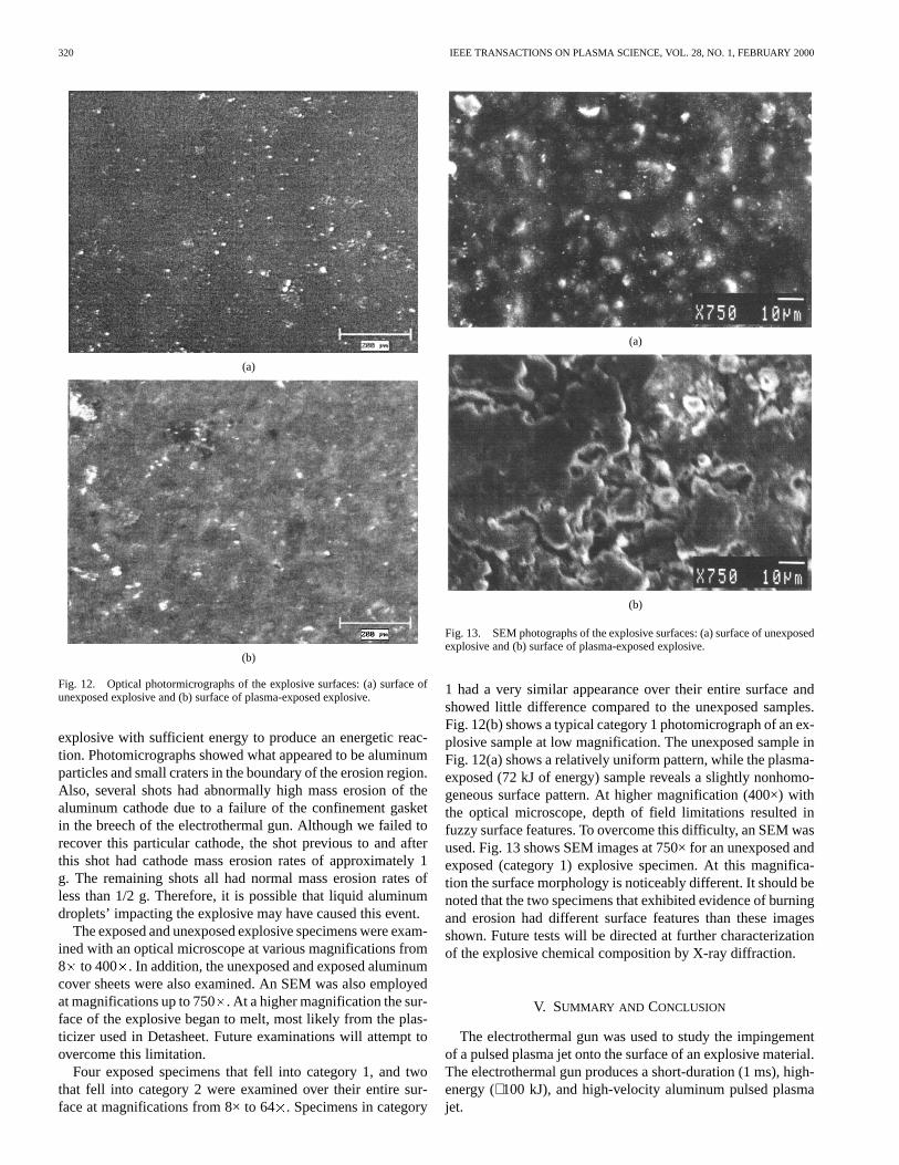
Fig. 12. Optical photormicrographs of the explosive surfaces: (a) surface ofunexposed explosive and (b) surface of plasma-exposed explosive.
explosive with sufficient energy to produce an energetic reac-tion. Photomicrographs showed what appeared to be aluminumparticles and small craters in the boundary of the erosion region.Also, several shots had abnormally high mass erosion of thealuminum cathode due to a failure of the confinement gasketin the breech of the electrothermal gun. Although we failed torecover this particular cathode, the shot previous to and afterthis shot had cathode mass erosion rates of approximately 1g. The remaining shots all had normal mass erosion rates ofless than 1/2 g. Therefore, it is possible that liquid aluminumdroplets’ impacting the explosive may have caused this event.
The exposed and unexposed explosive specimens were exam-ined with an optical microscope at various magnifications from8 to 400 . In addition, the unexposed and exposed aluminumcover sheets were also examined. An SEM was also employedat magnifications up to 750. At a higher magnification the sur-face of the explosive began to melt, most likely from the plas-ticizer used in Detasheet. Future examinations will attempt toovercome this limitation.
Four exposed specimens that fell into category 1, and twothat fell into category 2 were examined over their entire sur-face at magnifications from 8× to 64. Specimens in category
(a)
(b)
Fig. 13. SEM photographs of the explosive surfaces: (a) surface of unexposedexplosive and (b) surface of plasma-exposed explosive.
1 had a very similar appearance over their entire surface andshowed little difference compared to the unexposed samples.Fig. 12(b) shows a typical category 1 photomicrograph of an ex-plosive sample at low magnification. The unexposed sample inFig. 12(a) shows a relatively uniform pattern, while the plasma-exposed (72 kJ of energy) sample reveals a slightly nonhomo-geneous surface pattern. At higher magnification (400×) withthe optical microscope, depth of field limitations resulted infuzzy surface features. To overcome this difficulty, an SEM wasused. Fig. 13 shows SEM images at 750× for an unexposed andexposed (category 1) explosive specimen. At this magnifica-tion the surface morphology is noticeably different. It should benoted that the two specimens that exhibited evidence of burningand erosion had different surface features than these imagesshown. Future tests will be directed at further characterizationof the explosive chemical composition by X-ray diffraction.
V. SUMMARY AND CONCLUSION
The electrothermal gun was used to study the impingementof a pulsed plasma jet onto the surface of an explosive material.The electrothermal gun produces a short-duration (1 ms), high-energy (∼100 kJ), and high-velocity aluminum pulsed plasmajet.
KIM et al.: NEUTRALIZATION OF EXPLOSIVES BY PLASMA JET IMPINGEMENT 321
Temporal imaging of the plasma jet/explosive interaction inthe reaction chamber revealed distinctly different events that ap-pear to be a function of the plasma energy, mass eroded, andstand-off distance of the explosive. The most interesting eventis the double “flare” on the explosive surfaces at a time of 16and 23.5 ms after the plasma jet initiation. These events mightbe due to the surface reaction of the highly ionized aluminumplasma with the oxygen and nitrogen in the explosive specimen.One hypothesis is that the two reactions may lead to the forma-tion of microscale alumina (AlO ) and aluminum nitride (AlN)in the explosive. The presence of these inert microscale ceramicparticles may play a role in at least partially neutralizing the ex-plosive.
Results show that the degree of neutralization of the explo-sive is proportional to the impinged energy of the electrothermalplasma jet onto the explosive. From these preliminary results,we have also speculated that the neutralization of the explosiveis probably due to chemical reactions that react with the nitrogenand oxygen in the explosive composites, producing aluminumnitride and alumina.
Further research is currently under way to investigate the de-tailed processes that govern the physics of plasma jet/explosiveinteraction. Intriguing preliminary results have been obtained.The experiments will be continued with an eye to improvingour understanding of the chemical interaction between the alu-minum plasma and the specimen and to improving characteriza-tion of the processed specimen and of the reaction byproducts.
REFERENCES
[1] “Unexploded ordnance (UXO): An overview,” Federal Advisory Com-mittee for the Development of Innovative Technologies, Oct. 1996.
[2] C. King, Jane’s Mines and Mine Clearance,. London, U.K.: Jane’sInformation Group Ltd., 1996.
[3] J. M. Kohel, L. K. Su, N. T. Clemens, and P. L. Varghese, “Emissionspectroscopic measurements and analysis of a pulsed plasma jet,”IEEETrans. Magn., vol. 35, pp. 201–206, Jan. 1999.
[4] J. U. Kim, N. T. Clemens, and P. L. Varghese, “Experimental study of anunderexpanded pulsed plasma-jet,” inProc. AIAA, 1999, paper-99-0452.
[5] D. E. Wilson, K. Kim, and L. L. Raja, “Theoretical analysis of an ex-ternal pulsed plasma jet,”IEEE Trans. Magn., vol. 35, pp. 228–223, Jan.1999.
[6] K. Kim and D. E. Wilson, “Theoretical analysis of a plasma jet im-pinging on a nonreacting surface,” inProc. AIAA, 1999, paper 99-0455.
[7] J. G. Gilligan, M. A. Bourham, O. E. Hankins, O. Auciello, S. Tallavar-jula, and R. B. Mohanti, “Studies to reduce material erosion in elec-trothermal launchers,”IEEE Trans. Magn., vol. 27, pp. 476–481, Jan.1991.
[8] C. M. Edwards, M. A. Bourham, and J. G. Gilligan, “Experimentalstudies of the plasma-propellant interface for electrothermal-chemicallaunchers,”IEEE Trans. Magn., vol. 31, pp. 404–409, Jan. 1995.
[9] G. P. Wren, W. F. Oberle, A. Hosangadi, and N. Tonello, “Radiativeheating of solid propellant by an electrically-induced plasma source,”in Proc. AIAA, 1999, paper-99-0589.
[10] O. E. Hankins, M. A. Bourham, J. Earnhart, and J. G. Gilligan, “Vis-ible light emission measurements from a dense electrothermal launcherplasma,”IEEE Trans. Magn., vol. 29, pp. 1158–1161, Jan. 1993.
[11] D. Hewkin and E. Figura, “Fundamental research and numerical mod-eling of the internal ballistics of electrothermal chemical guns,”IEEETrans. Magn., vol. 29, pp. 561–566, Jan. 1993.
[12] J. R. Greig, J. Earnhart, N. Winsor, H. A. McElroy, A. A. Juhasz, G.P. Wren, and W. F. Morrison, “Investigation of plasma-augmented solidpropellant interior ballistics processes,”IEEE Trans. Magn., vol. 29, pp.555–560, Jan. 1993.
[13] G. P. Wren, W. F. Oberle, N. Sinha, A. Hosangadi, and S. M. Dash,“US Army activities in multidimensional modeling of electrothermal-chemical guns,”IEEE Trans. Magn., vol. 29, pp. 631–636, Jan. 1993.
[14] C. R. Woodley, “A parametric study for an electrothermal-chemical ar-tillery weapon,”IEEE Trans. Magn., vol. 29, pp. 625–630, Jan. 1993.
[15] G. L. Katulka, “A parametric study of high energy plasmas for elec-trothermal-chemical propulsion applications,”IEEE Trans. Plasma Sci.,vol. 25, pp. 66–72, Feb. 1997.
[16] D. R. Peterson, “Electrothermal-chemical synthesis of nanocrystallineceramics,” Ph.D. dissertation, The University of Texas at Austin, Austin,TX, 1994.
[17] , “Design and operation of the electrothermal gun for producingmetal and carbon plasma jets,”IEEE Trans. Magn., vol. 33, pp. 373–378,Jan. 1997.
[18] L. L. Raja, P. L. Varghese, and D. E. Wilson, “Modeling of the electrogunmetal vapor plasma discharge,”J. Thermophys. Heat Transfer, vol. 11,no. 3, pp. 353–360, 1997.
Jong-Uk Kim received the B.S. and M.S. degreesin physics from the Hankuk University of ForeignStudies, Seoul, Korea, in 1986 and 1988, respectively,and the Ph.D. degree in physics from Michigan StateUniversity, East Lansing, in 1997.
He is currently a Postdoctoral Fellow at theInstitute for Advanced Technology and the Depart-ment of Aerospace Engineering and EngineeringMechanics, The University of Texas at Austin,where he is actively involved in research work in thefield of applied physics for engineering applications.
His research interests include laser diagnostic techniques, plasma-explosiveinteractions, pulsed power, optical emission spectroscopy, and nanoparticlecharacterizations.
Kyoungjin Kim was born in Seoul, Korea, onNovember 23, 1965. He received the B.S. and M.S.degrees from Seoul National University in 1988and 1990, respectively, and the Ph.D. degree fromThe University of Texas at Austin in 1998, all inmechanical engineering.
Since 1998, he has been a Postdoctoral Fellow inthe Institute for Advanced Technology, Austin, TX,and a Lecturer in the Department of Mechanical En-gineering at the University of Texas at Austin. Hisresearch interests include the numerical modeling of
metal vapor plasma jet, the electrothermal–chemical gun operation, and the for-mation of nanophase particles using metal vapor plasma as well as the numericalsimulation of the unsteady boundary layer flows and the modeling of turbulentand transitional flows.
Dennis E. Wilsonwas born in Carrizo Springs, TX,on October 19, 1947. He received the B.S., M.S.,and Ph.D. degrees in mechanical engineering fromThe University of Texas at Austin in 1970, 1973,and 1977, respectively.
Since 1985, he has been on the Faculty in theThermal/Fluids Systems Group of the MechanicalEngineering Department at The University ofTexas at Austin, where he is currently an AssociateProfessor. He also served as Director of SpecialProjects for the Institute for Advanced Technology,
Austin. His expertise is in the general area of theoretical fluid dynamics,heat transfer, and applied mathematics. Most recently, his research interestshave been in high-speed fluid dynamics, plasma dynamics, and unsteady heattransfer. He has worked on a wide variety of research topics in these areas,which include novel heat flux reduction schemes associated with hypersonicflight vehicles; shock/shock intersections; explosively driven launchers;electrothermal chemical gun propulsion; underwater shock wave formation andpropagation; unsteady effects in reattaching flows; and freestream turbulenceeffects on boundary layer heat transfer.

322 IEEE TRANSACTIONS ON PLASMA SCIENCE, VOL. 28, NO. 1, FEBRUARY 2000
Dennis R. Petersonwas born in Laramie, WY, in1945. He received the B.S.M.E. and M.S.M.E. de-grees from the University of Wyoming, Laramie, andthe Ph.D. degree in materials science and engineeringfrom The University of Texas at Austin.
He has been a Mechanical Engineer at the AdolphCoors Company and a Researcher at Los Alamosand several institutes of The University of Texas:the Center for Electromechanics, the Institute forAdvanced Technology, and the Applied ResearchLaboratory. Currently, he is Vice President for
technology at Nanoscale Engineering and Technology Corporation, Austin,TX. His research interests include pulsed power, railguns, and electrothermalguns for defense applications and the conversion of those technologies tocommercial and scientific applications. With his colleagues, he has publishednumerous journal articles and has frequently served as a reviewer. He hasreceived several patents and has several pending. He has been involved inthe organization of conferences and has served on advisory panels of theDepartment of Defense and the Department of Energy.
Noel T. Clemensreceived the B.S. degree from the University of Massachusettsat Amherst in 1985 and the M.S. and Ph.D. degrees from Stanford University,Stanford, CA, in 1986 and 1991, respectively, all in mechanical engineering.
From 1991 to 1993, he was a Postdoctoral Fellow at the Combustion ResearchFacility at Sandia National Laboratories, Livermore, CA, where he specializedin applications of laser imaging techniques to gas-phase combustion research.In 1993, he became an Assistant Professor in the Department of Aerospace En-gineering and Engineering Mechanics at The University of Texas at Austin. In1999, he became an Associate Professor. His research interests include appli-cations of laser diagnostic techniques, plasma-propellant interactions, turbulentmixing and combustion, and supersonic unsteady flows.