Neuromax 1000
113
NeuroMax User Manual TM ... making medicalconnections XL TEK NeuroMax User Manual XL TEK Part Number 101924 REV D 1. WELCOME TO THE NEUROMAX ......... .............. 9 1. 1. i NTRODUCTION ............... .. .................................... l 0 1.2. W ARRANTY .................................. ........ ................ 10 1.3. USI NG THE MANUAL ............................................ I0 2. THE NEUROMAX ......................... . ............ ... ...... 13 2.l. OPERATING CONDITI ONS .................................. .... 13 2.1 .1. Environment Parameters .... .. ...... ........................... 13 2. 1.2. Transport and Storage Parameters .......... .... .. .. .. ... 13 2.2. WARNINGS AND CAUTIONS ................... ............... 13 2.2.1. Wamings .. .. .............. .. .................................... .. .. ... 14 2.2.2. Cautions ........ .. .......................... .......................... .. 16 2.3 . MAIN MENU ......................................................... 18 2.4. KEY PAD .................................. ...... ........... ........... 19 2.5. HOT KEYS ................................................... ......... 23 2.5 . 1. Sensory Nerve Conduction Hot Keys ...... .............. 23 2.5.2 . Electromyography Hot Keys .................................. 23 2.5.3. Evoked Potential Hot Keys ............ ...... .......... .. : ..... 23 2.6. CREATING A PATIENT FILE ........ .................... ....... 24 2.7. GENERATI NG T EST REPORTS ......................... ....... 25 2. 7 .1. Report Functions .................. ... ...... ...... .......... ........ 26 3. NERVE CONDUCTION TESTS .. .' ....................... 29 3.1. MOTOR AND S ENSORY NERVE CONDUCTIONS ...... 30 3.1.1. Setting Up a Nerve Conduction Study .... ........ .. ..... 30 3.1.2. Conducting an NCS ................. .. ............................ 32 3.1.3. F-Wave and Rep-Stim Tests ........ .. .................. . ..... 33 3.1.4. Recording F- Wave and Rep-Stim Tests ................ 35 3. 1.5. Setting Up an H- Reftex Test... ............................... 36 3. 1.6. Acquiring H- Reftex Responses .. .... ........................ 36 4. ELECTROMYOGRAPHY (EMG) TESTS ........... 37 4.1. SETTING UP THE EMG T EST MEN U ... .. ................. 37 4. 1.1. Setting Up an EMG ............ . ... ...... .. ............ ........... 37 4.1.2. Acquiring an EMG ...................... .. ......................... 38 4.2. FREE RUN EMG fEATURES .. .. .................... ......... 39 4.2.1. Reviewing Free Run EMG .. ... ................................ 39 XLTEK 1
-
Upload
victor-rebollar -
Category
Documents
-
view
665 -
download
40
Transcript of Neuromax 1000

NeuroMax User Manual
TM
... making medical connections
XL TEK NeuroMax User Manual XL TEK Part Number 101924 REV D
1. WELCOME TO THE NEUROMAX ....................... 9 1.1. i NTRODUCTION ..... ................................................ l 0 1.2. W ARRANTY .. ... ........ .... ............... .......... ................ 10 1.3. USING THE MANUAL ............ .............. .. .. .. ...... ...... I 0
2. THE NEUROMAX ............................................... 13
2.l. OPERATING CONDITIONS ...................................... 13 2.1.1. Environment Parameters .... ................................... 13 2.1.2. Transport and Storage Parameters ................ .... ... 13
2.2. WARNINGS AND CAUTIONS ................... .............. . 13 2.2.1. Wamings .. .. ................ ........................................ ... 14 2.2.2. Cautions ........ .. .......................... ............................ 16
2.3. MAIN MENU ................... .. .... ....... ......................... 18 2.4. KEY PAD ..................................... .............. .... ....... 19
2.5. HOT KEYS ..................................................... ....... 23 2.5.1. Sensory Nerve Conduction Hot Keys .................... 23 2.5.2. Electromyography Hot Keys .................................. 23 2.5.3. Evoked Potential Hot Keys .............. .... ............ : ..... 23
2.6. CREATING A PATIENT FILE .. .... ...................... ....... 24 2.7. GENERATING T EST REPORTS ................................ 25
2. 7 .1. Report Functions ..................... .............................. 26
3. NERVE CONDUCTION TESTS .. .' ....................... 29 3.1. MOTOR AND SENSORY NERVE CONDUCTIONS .... .. 30
3.1.1. Setting Up a Nerve Conduction Study .... ........ .. ..... 30 3.1.2. Conducting an NCS ................... ............................ 32 3.1.3. F-Wave and Rep-Stim Tests .......... ........................ 33 3.1.4. Recording F-Wave and Rep-Stim Tests ................ 35 3.1.5. Setting Up an H-Reftex Test... ............................... 36 3.1.6. Acquiring H-Reftex Responses .. .... ........................ 36
4. ELECTROMYOGRAPHY (EMG) TESTS ........... 37
4.1. SETTING UP THE EMG T EST MENU ..... ................. 37 4.1.1. Setting Up an EMG ................ ...... ......................... 37 4.1.2. Acquiring an EMG ........................ ......................... 38
4.2. FREE RUN EMG fEATURES .. ~ .. ............................. 39 4.2.1. Reviewing Free Run EMG ..................................... 39
XLTEK 1

User Manual NeuroMax
4.2.2. Analyzing Tums and Amplitude ....... .... ...... ........... 39 4.3. TRJGGERED EMG FEATURES ... ........................... . .40
4.3.1. Activating Triggers .................. .............................. 40 4.3.2. Saving a Test. ... .... .. ..... ........... ....... ... .. ................ .. 41 4.3.3. Analyzing and Reviewing Motor Units ... .... ............ 41
4.4. FAST TRJGGERED EMG FEATURES ....... .......... ..... .42
4.4.1. Reviewing and Editing Fast Triggered Tests ........ .42 4.4.2. Calculating MCD ............. .......................... ... ......... 43
5. OTHER TESTS .................................................. 45
5.1 . OTHER T ESTS .... ..... .. ...... .... ........ ........ .................. .45
5.1.1. Setting Up Evoked Potentials (EP) ....... ....... ......... 45 5.1 .2. Conducting Evoked Potentials ... .......... ................. 46 5.1.3. SEP Tests .................... .................. ........... ... ......... 47 5.1.4. Suggested SEP Protocols ................... .................. 48 5.1.5. Dermatomal SEPs ............ ........ ............................ 49
5.2. BLINK REFLEX ... ..... ... .. ....... ..... ........ ..................... 51
5.2.1. Setting Up a Blink Reflex Test ... ........................... 51 5.2.2. Conducting Blink Reflex Tests ........ ...................... 51
5.3. INCREMENTAL STIMULATION ..... ..... .... .. ................ 52
5.3.1. Setting Up Incremental Stimulation Tests ............. 52 5.3.2. Conducting Incremental Stimulation Tests ............ 52
5.4. H EART RATE VARIABILITY (HRV) .. .............. ..... .. 53
5.4.1. Setting Up HRV Stimulation Tests ........................ 53 5.4.2. Conducting HRV Tests ...... .. .. ........ .............. ......... 54 5.4.3. SSR-The Sympathetic Skin Response ........... .... .. 54
5.5. MULTI-CHANNEL EMG/IOM .... ... ......... .... ... .... ..... 55 5.6. M ULTI-CHANNEL N ERVE CONDUCTIONS ... .... ....... 56
5.7. THE P300 T EST ..... .... .. ....... .......................... .... ..... 56 5. 7 .1. Getting Started ............................... ........... ............ 56 5.7.2. Running the Test... ............................................. : .. 57 5.7.3. Hints and Features .. ........... .. ........... .................... .. 58 5.7.4. Explanation of Options ......................... ........ .. ....... 59
6. AV STIM 1000 .................................................... 61
6.1. AV STIM 1000 FRONT PANEL. .... ......... ...... ........ .. 61 6.2. AV STIM 1000 REAR PANEL ................... .... .... ... .. 61 6.3. CONNECTING THE A V STIM I 000 ...................... .. 62 6.4. WARNINGS AND CAUTIONS ........ ... .... .. ... .. .. . 63
6.4.1. Warnings ............................................................... 63 6.4.2. Cautions .................... ... .......... ............................... 64
6.5. CALI BRA TJON AND MAINTENANCE ....................... 64 6.6. SUGGESTED AEP PROTOCOLS ................ .... .......... 65
6.6.1. AEP Impedance Check ............ ...... .................. ..... 65 6.7. SUGGESTED YEP PROTOCOLS .. .. .......................... 66
6.7.1. VEP Impedance Check .................. ............ ........... 66 6.8. A CQUIRING A FULLFIELD YEP RESPONSE ............ 67
2 XLTEK

NeuroMax User Manual
6.9. ACQUIRING A H EMIFIELD YEP RESPONSE ........... 68
7. SETTING THE DEFAULTS ................................ 69 7 . I. TEST MENU PARAMETERS .... ... ............... ........ .... .. 69
7 .1.1. Creating an Electromyography Suite ..................... 69 7.2. EDITfNG TEST D EFAULTS ... .... .. ....... .. .... ............... 70
8. ADMINISTRATIVE FUNCTIONS ....................... 73
8.1. ADMINISTRATIVE FUNCTIONS ............... ....... ...... .. 73 8.1.1. Patient Directory ...................... ........... .. .. .... ........... 73 8.1.2. Memory Management ............................ .... ........... 74 8.1.3. Batch Print... ........................... ............................... 76 8.1.4. System Options ...................................... ............ ... 76 8.1.5. Edit Report Format ............. ................................... 76 8.1.6. Edit Site Name List... .. ......... .................................. 77 8.1.7. Edit EMG Notepad .... ................................ .. .......... 77 8.1.8. Edit Patient Information Fields .............................. 77 8.1.9. Changing the Date on Stored Data .... ....... ............ 77
8.2. ARCHIVER ....... ... ... .... ... ... ......... ......... ............... .... 78 8.2.1 . Installing Archiver on a Computer .... ... .. ................ 78 8.2.2. Starting Archiver .................................................... 79 8.2.3. Transferring NeuroMax Files to a PC ............... ..... 79
8.3. MANAGING THE REPORTS ... .. ............. ... ................ 81 8.3.1. Rich Text Files (RTF) ............. .. ............................. 81 8.3.2. Viewing Patient Reports ...... .. ..................... .. .... .. ... 81 8.3.3. Printing Patient Reports ........................................ 82 8.3.4. Editing Patient Reports ............ ............... ............... 82 8.3.5. Editing Fast Triggered Studies ................ .............. 82 8.3.6. Printing the Waveforms in Archiver ......... ....... ... .... 83
9. APPENDIX 1: WARRANTIES ............................ 85
9.1. WARRANTY INFORMATION ....... ... ............ .. . 85 9.1.1. NeuroMax Warranty Service .................. ............. .. 85
9.2. EXTENT OF LIMITED WARRANTY ......................... 85 9.3 . LIMITATIONS OF W ARRANTY ............................. ... 86 9.4. LIMITATIONS OF LIABILITY .................................. 86 9.5. EXTENDED WARRANTY JNFORMA TION ... 86 9.6. NEUROMAX MAINTENANCE SERVICE .......... .. ..... . 87 9.7. 24 HR REPLACEMENT GUARANTEE ............ 87 9.8. PRICING .. ............... ...... ..... ...... .... ........ .. ................ 87 9.9. XL TEK WARRANTY DEFINITIONS ...... ... .. ............ 87
9.9.1. Hardware Service ................. ................................. 87 9.9.2. Clinical Support Service ................................... .. ... 87
10. APPENDIX 2: NEUROMAX IN-SERVICE CHECKLIST ............................................................... 89
I 0.1. B ASIC FUNCTIONS ... .. ....... .. ....... .. ........ .. .. ...... ..... 89
XLTEK 3

User Manual NeuroMax
1 0.2. NERVE CONDUCTION FUNCTIONS .. ..................... 89 10.3. ELECTROMYOGRAPHY ........................... ........ ..... 89 10.4. ADMINISTRATIVE FUNCTIONS ........ .. .............. ..... 90 1 0.5. D UAL CHANNEL T ESTS ................................ . . ... .. 90 1 0.6. REPORT MENU .. ... ..... ..... .. .... ... .. .. ... ..................... 90 1 0.7. A CCESSORIES ... .. ... .. ............................ ... ... ...... ... . 90 1 0.8. CONFIRMTION .. ....... .. ..... ................................ 91
11. APPENDIX 3: TROUBLESHOOTING/MAINTENANCE ................... 93
11.1 . SOFTWARE ......... .. ..... .. ...... .. .... . . ... ... .. ... ..... .... . ..... 93 11.1 .1. Checking Software Version on NeuroMax .......... 93 11.1.2. Updating Software .. ............................................ 93 11.1 .3. Installing NeuroMax Loader .. .. .............. ... ........... 94 11 .1.4. Using NeuroMax Loader .......... ...... ..................... 94
11 .2. NERVE CONDUCTIONS ... ..................................... 95 11 .2.1 . Creating a NCS ............................ .. .......... ........ ... 95 11 .2.2. Editing an NCS ................................................... 95 11.2.3. Setting Up Stimulus and Recording Sites ......... .. 95
11.3. ELECTROMYOGRAPHY ...................................... .. 96 11 .3.1 . Creating an Electromyography Suite .................. 96 11 .3.2. Using an Electromyography Suite ....................... 96
11.4. ADMINISTRATIVE FUNCTIONS ........... .................. 97 11.4.1. Editing Studies .................................................... 97 11.4.2. Interpretation Macros ............................. ............. 97
1 1.5. TROUBLESHOOTING ..... ....... .. .............................. 98 11 .5.1. Signal Clipping in NCS and EMG ........................ 98 11 .5.2. Stimulus Artifact ............................................ ...... 98 11 .5.3. Electrode Impedance .......................................... 99 11 .5.4. Skin Preparation ................................................. 99 11 .5.5. Electrode Type and Placement.. .. ............ .. .. ..... 100 11.5.6. Stimulator ...... .. ............. ............ .. ... .. .................. 101
11.6. AV STIM ......... ... ....... .................... ... .... ... .. ..... ... I03 11 .7. PRINTING ... ....... . .... . . ... .... ...... .... .. . ........ .. ........... 104
11.7 .1. NeuroMax ................................. ............ ............ 1 04 11 .7.2. Printer ..... ..................... ..... ................................ 104
I 1.8. P REVENTATIVE M AINTENANCE ............. ........ .... 1 04 11.8.1. NeuroMax Enclosure ........................................ 105 11 .8.2. Keypad ... ........................................................... 105 11 .8.3. Screen ................................................ .............. 105 11.8.4. Back Panel/Connectors ..... ..... ......... ............ .. .. .. 105 11.8.5. Head box and Cable .............. ............ .. .. .. .......... 106 11 .8.6. Stimulus Probe and Cable ................................ 106 11 .8.7. Printer and Cable ...... .. .... ............... .. .... ........ .. ... 106 11 .8.8. Electrodes and Accessories .............................. 106
11 .9. USER ADJUSTMENTS ......................................... 107 11 .9.1. No Electrical Stimulus ....................................... 107
4 XlTEK

NeuroMax User Manual
11 .9.2. No Response from Patient Electrodes .............. 108 11 .9.3. Large Stimulus Artifact ...................................... 108 11.9.4. Noisy Data .... .. ................................................... 109 11.9.5. Unit Does Not Power On ................................... 110 11.9.6. Error Messages ................................................. 110
11.1 0. CALIBRATING THE NEUROMAX ...................... 114 11 .1 0.1. Calibrating the Stimulator: ............................... 114 11 .1 0.2. Checking the Waveform .................................. 114
12. APPENDIX 4: XLTEK DIAGNOSTIC ACCESSORIES ....................................................... 115
12.1 . INTRODUCTION ..................................... .... ........ 115 12.2. HOW TO ORDER ................................................. 115 12.3. DESIGN AND QUALITY ....................................... 117 12.4. ORDER FORM ... ............... ....... .. .. ........................ 121
INDEX ...................................................................... 123
: XLTEK 5

\ \_/
"--"'.

NeuroMax
PUBLISHED BY Excel Tech Ltd. 2568 Bristol Circle Oakville, Ontario, CANADA L6H 5S1 Toll Free: 1-800-387-7516, Fax: (905) 829-5304 Email: [email protected]
NOTIFIED BODY British Standards Institution (Re: # 0086) Product Services Maylands Avenue Hemel Hempstead, Hertfordshire HP24SQ UNITED KINGDOM Phone: 44 (0)1442-230442
NOTIFIED BODY TOV Rheinland (Re: # 0197) Product Safety GmbH Am Grauen Stein/Konstantin-Wille-Str. 1 51105 Koln Postal address: 51101 Koln GERMANY
AUTHORIZED REPRESENTATIVE mdi Europa GMBH Michael Bain Wittekamp 30 D-30163 Hannover, GERMANY Phone: 49-511-3908-9539, Fax: 49-511-3908-9539
Copyright© 2003 by Excel Tech Ltd.
User Manual
The information in this publication is provided for reference only. All information contained in this publication is believed to be correct and complete. Excel Tech Ltd. shall not be liable for errors contained herein nor for incidental or consequential damages in connection with the furnishing, performance, or use of this material. All product specifications, as well as the information contained in this publication, are subject to change without notice.
This publication may contain or reference information and products protected by copyrights or patents and does not convey any license under the patent rights of Excel Tech Ltd., nor the rights of others. Excel Tech Ltd. does not assume any liability arising out of any infringements of patents or other rights of third parties.
- XlTEK 7

User Manual NeuroMax
All rights reserved. This document contains confidential or proprietary information of Excel Tech Ltd. No part of this document may be reproduced or transmitted in any form or by any means without the written permission of Excel Tech Ltd.
Excel Tech Ltd. makes no warranty of any kind with regard to this material, including but not limited to the implied warranties of merchantability and fitness of a particular purpose.
8

NeuroMax User Manual
1. WELCOME TO THE NEUROMAX
Congratulations, you have purchased the NeuroMax from XL TEK, one of the world's top manufacturers of neurodiagnostic equipment and software. XL TEK is an ISO 9001 certified company committed to excellence and to providing you with the latest in technology and software.
The NeuroMax offers full-featured EMG in a simple, easy to use, and affordable line of instruments. XL TEK NeuroMax is available in two and four-channel format and provides you with the highest performance and greatest reliability of any EMG instrument on the market. From simple NCS studies through to a complex quantitative EMG, the XL TEK NeuroMax is the system you can rely on.
XL TEK NeuroMax 1002 Two-channel neurodiagnostic for basic and advanced NCS, EMG, and EP. Incorporates a large 12.1" XGA (1024 x 768) screen. Advanced engineering and the latest in technology allow for improved performance and speed, advanced NCS capabilities, advanced EMG capabilities, and advanced Multi-Channel Studies.
XL TEK NeuroMax 1004 Four-channel neurodiagnostic for basic and advanced NCS, EMG, and EP. Incorporates a large 12.1" XGA (1024 x 768) screen. Advanced engineering and the latest in technology allow for improved performance and speed, advanced NCS capabilities, advanced EMG capabilities, and advanced Multi-Channel Studies.
XL TEK Head boxes and Accessories
XLTEK provides two and four-channel headboxes, AV Stimulators, and a full range of accessories.
: XLTEK 9

User Manual NeuroMax
1.1. INTRODUCTION
XL TEK 's commitment to quality is demonstrated by its unique standing as the only manufacturer in the industry that uses a vertically integrated process to design, build, test, distribute, and support its equipment. Retaining all of the processes within the organization enables XLTEK to maintain absolute control over the quality of its equipment. At the same time, XL TEK has the flexibility to improve products continually to meet the needs of its clients. We thus encourage all feedback and any suggestions you have regarding any aspect of the EMG system, the manual, our line of accessories, and our support services. Please see Appendix 3 for contact information.
1.2. WARRANTY
XLTEK stands behind the quality of its products and warrants to its customers that products will be free from defects in materials and workmanship for a specified time after the date of purchase by the customer. Extended warranty options are also available for all XL TEK products. Complete warranty details are provided in Appendix 1.
1.3. USING THE MANUAL
10
XL TEK is committed to providing you with clear instructions and unqualified support so you can operate our equipment with ease and confidence.
The warranty information for the individual models is found in the appendices at the back of the manual. We have also included our Accessories catalog for your convenience.
The manual presents step-by-step instructions which take you through the testing, customizing, and operation of the equipment and software so that our system meets your specific needs. It will guide you through the acquisition of a patient record and its review, storage, and recall. You will learn how to develop a report and to archive studies for future reference.
For your convenience, a thorough Table of Contents is provided which details the topics covered in each chapter. An Index is also available at the back of the manual.
~XLTEK

::()-: ''i' TIPS
NeuroMax User Manual
The in-depth procedures describe the detailed operation and customization of the EMG system. The procedures, which are accompanied by detailed graphics, are designed to tailor the system to your specific circumstances. We encourage all users to explore the manual and to take advantage of everything that XL TEK has designed the EMG system to do.
When going through the procedures, we recommend that you read the whole section before starting the sequence. Please follow the instructions carefully.
We have also placed TIPS and NOTES alongside the instructions. These will list Hot Keys, operation tips, shortcuts, and testing information.
XLTEK
XlTEK 11
NOTES

NeuroMax User Manual
2. THE NEUROMAX
The NeuroMax is designed to conduct a range of tests, including Nerve Conduction Studies (NCS), Electromyography Studies (EMG), and other tests such as Evoked Potentials, Blink Reflex, Incremental Stimulation, and Heart Rate Variability.
This chapter takes you through the Warnings and Cautions you need to observe while operating the NeuroMax and introduces you to its basic functions.
2.1 . OPERATING CONDITIONS
The NeuroMax is designed for optimum performance under safe conditions. To ensure the safety of the operator and of the patient, please read the following sections carefully.
2.1.1. ENVIRONMENT PARAMETERS
Temperature Range: Relative Humidity range: Atmospheric pressure range:
+1 0 to +40 degrees Celsius 30% to 75% 700hPa to 1 ,060hPa
Altitude: To a maximum of 4600 meters *above sea level
2.1.2. TRANSPORT AND STORAGE PARAMETERS
Ambient Temperature Range: -40 to +70 degrees Celsius Relative Humidity Range: 10% to 100%, including
condensation Atmospheric Pressure Range: 500hPa to 1 ,060hPa
2.2. WARNINGS AND CAUTIONS
The following Warnings and Cautions are marked with a
& and must be followed very closely to ensure the safety of both the patient and the user of the NeuroMax and the AV Stirn. It is therefore important to read and observe ALL of the Warnings and Cautions before attempting to use the NeuroMax and the AV Stirn.
If there is any malfunction or perceived malfunction of the system, please call an authorized XL TEK service representative immediately at 1-800-387-7516. All internal
13

User Manual NeuroMax
system checks and/or service must only be conducted by an authorized XL TEK service representative.
IMPORTANT: 'SYSTEM' REFERS TO THE NEUROMAX, AV STIM, AND ALL ACCESSORIES A IT ACHED TO IT.
The NeuroMax and AV Slim carry the ordinary equipment classification (as per IEC 529) for the level of protection against ingress of liquids. They are not drip or splash proof.
Regarding protection against electrical shock, the NeuroMax and AV Slim are classified as Class I devices (as per EN 60601-1 ). The NeuroMax requires a properly grounded electrical outlet. The mode of operation for both the NeuroMax and AV Slim is continuous operation.
2.2.1. WARNINGS
14
Warnings MUST be followed when using the equipment. Warnings apply to conditions which can injure the patient and/or the operator.
WARNING: Care must be taken in the delivery of any level of stimulus. If used improperly, injury may be caused to the patient. The delivery of stimulus to the patient is done through the Start/Stop key on the NeuroMax and the stimulus probe.
WARNING: The level of stimulator intensity is controlled by the Up/Down arrows on the NeuroMax and the stimulation probe and is displayed on the active test screen in rnA. Close attention must be paid to the level of stimulus intensity and the duration of the impulse. This unit has enough electrical power to harm a patient if used improperly.
WARNING: This system must only be plugged into a properly grounded electrical outlet. The internal isolation transformer of the system must not be bypassed, under any circumstances.
WARNING: Hazardous voltages are exposed when the lid of the NeuroMax is removed.
XlTEK
J

NeuroMax User Manual
WARNING: This system is not suitable for use in the presence of flammable mixtures. The system is not AP or APG rated.
WARNING: Do not turn the system on until all cable connections are made and their integrity is checked.
WARNING: The proper use of this device for its intended purpose can only be assured once all instructions have been read and understood. If there are any questions regarding the operation of this device, contact your XL TEK representative at once.
WARNING: The sale, distribution, or use of this device is restricted to by, or on order of, a licensed medical practitioner.
WARNING: The NeuroMax and the AV Stirn are Type BF devices (as per EN 60601-1 ) regarding degree of protection against electrical shock. The BF device is an applied part isolated from other parts of the EQUIPMENT to such a degree that that no current higher than the PATIENT LEAKAGE CURRENT allowable in SINGLE FAULT CONDITION flows if an intended voltage originating from an external source is connected to the PATIENT, and thereby applied between the APPLIED PART and the ground. All of the patient connections of the NeuroMax are electrically isolated; however, these connections are not intended for direct cardiac contact.
XLTEK 15

User Manual NeuroMax
WARNING: If the NeuroMax is inside a patient environment, then only the XL TEK opto-isolator cable shall connect a printer to the printer port. The printer is then electrically isolated to prevent any leakage of current from the printer to the NeuroMax. The AV Stirn contains a built-in optoisolator for connection to a printer.
If a printer is connected to the NeuroMax through the opto-isolator adapter cable or the AV Stirn and is inside the patient environment, it shall be powered from a medical grade safety isolation transformer complying to IEC 601-1.
No equipment other than devices connected to the NeuroMax/AV Stirn may be powered by the isolation transformer. The current rating of the transformer must be sufficient to operate all of the devices powered by it. Refer to the current ratings of each individual device.
WARNING: Non-medical electrical equipment (printers and computers) complying with the appropriate IEC or ISO safety standards may be directly connected to the NeuroMax and AV Stirn for printer and data-transfer functions ONLY if both the NeuroMax and AV Stirn and the equipment are outside of the patient environment and no patientapplied parts are connected to the patient.
WARNING: Possible interference with EMG and Nerve Conduction signals may occur in certain situations (i.e. poor grounding in circuitry, close proximity to other instrumentation such as an MRI).
2.2.2. CAUTIONS
16
Cautions must be noted when using the equipment. Cautions apply to conditions which may damage the NeuroMax.
CAUTION: It is recommended that the stimulator probe be disinfected between patients with 70% isopropyl alcohol. This is not an appropriate method of sterilization if the stimulator is used invasively.
XLTEK

NeuroMax User Manual
& CAUTION: Turn off all system power and r disconnect the power cord from the system and
the wall before attempting to clean the unit. The NeuroMax and the AV Stirn can be wiped clean with a damp cloth using non-conductive distilled water, electrically non-conductive inert surfactants, or a cold sterilizing agent. It is important to dry off the units quickly. Avoid letting liquid seep into any of the internal electronics of the system. The screen of the NeuroMax is more sensitive to liquid damage than the other components of the NeuroMax, so be careful to wipe off liquid spots immediately. Use a soft cloth on the screen. Do not use any abrasive cleaner on the system. Refer to AV Stirn Manual for detailed cleaning instructions for the headphones and goggles used with the AV Stirn.
& CAUTION: Method of sterilization or disinfection classification: no method.
& CAUTION: Inspect all cables and connections (especially the power cord) often for signs of fraying or other damage. Do not operate either the NeuroMax or the AV Stirn if you suspect damage to any of the cables or the power cord.
& CAUTION: Do not leave any cables attached to the back panel of the NeuroMax I AV Stirn when transporting the unit - this may cause the back panel connections to become loose, or malfunction during operation of the unit.
& CAUTION: Pay particular attention to the care of the NeuroMax screen. Do not attempt to remove the protective cover. The screen itself uses a glass panel, which may crack or break if it is dropped or bumped on a hard surface. Handle with care.
& CAUTION: Do not tum on the power to the NeuroMax and/or the AV Stirn immediately after bringing either unit from a cold environment to room temperature. Allow the units to assume ambient environmental temperature (one-hour warm up).
XLTEK~ 17

User Manual NeuroMax
2.3. MAIN MENU
18
The NeuroMax opens to the Main Menu screen and lists the five menu choices available to you.
Figure 2.1: Main Menu
Choices 1-3 are the studies available on the NeuroMax:
(1) Nerve Conduction: Test motor nerve conduction,
sensory nerve conduction, F-Wave, Rep Stirn, and
H-reflex.
(2) Electromyography: Test muscle activity with
FreeRun EMG, Triggered EMG, and Fast Triggered
EMG.
(3) Other Tests: Includes Evoked Potentials, Blink
Reflex, Incremental Stirn, and Heart Rate
Variability, Multi-Channel EMG, and Multi-Channel
NCS.
XlTEK

Function Keys
Alphanumeric Keyboard
NeuroMax User Manual
2.4. KEY PAD
The keypad is divided into four sections, each with its own set of functions.
Figure 2.2: Key Pad
Alphanumeric Keyboard Follows the familiar QWERTY pattern used on most computer keyboards.
XLTEK 19
Control Keys
Select Keys

User Manual NeuroMax
20
Control Keys: Operate audio, stimulation, and trigger levels.
Figure 2.3: Control Keys
Select Keys: The Select arrows control the option selections and the Select key is main entry key.
Figure 2.4: Select Keys
- xLTEK

NeuroMax User Manual
Function Keys: Perform and customize neurological tests.
Figure 2.5: Function Keys
The Function key operations are listed below:
TRACE FUNCTION KEY
Move, smooth, re-assign, and superimpose traces Review stored EMG Number of traces to raster
SETTINGS FUNCTION KEY
Low-frequency, high-frequency and notch filters Amplifier and Display Gain, timebase and sweep delay TriQQer delay/slope
CURSORS FUNCTION KEY
Latency and amplitude cursors Adjust position and add cursors
DISTANCE FUNCTION KEY
Segment distances in mm Conduction velocity calculated
XLTEK 21

User Manual
STIMULATOR FUNCTION KEY
Pulse duration, stim frequency, mode and max. intensity Number of pulses/train AV Stimulator parameters
NOTES FUNCTION KEY
Needle EMG notepad Enter test comments Edit site names
ERASE FUNCTION KEY
Erase single or multiple traces Erase sets of data
AVERAGER FUNCTION KEY
Tum Averager On/Off Acquire EP responses
SELECT FUNCTION KEY
Choose highlighted menu selection
NeuroMax
22 : XLTEK

NeuroMax User Manual
2.5. HOT KEYS
The Hot Keys activate functions during an acquisition, providing a quick and immediate response. They will be noted in the Notes and Tips when applicable.
2.5.1. SENSORY NERVE CONDUCTION HOT KEYS
KEY FUNCTION
Space Bar - if in full screen mode, averaging and single acquisition mode, deletes the latest acquisition from the average
X - post processing artifact extraction
2.5.2. ELECTROMYOGRAPHY HOT KEYS
KEY FUNCTION
TRIGGER - go to Triggered from FreeRun or Fast 1,2 Triggered F - go to FreeRun from Triggered or Fast
Triggered s - go to Fast Triggered from FreeRun or
Triggered F - in Free Run, hit StarUStop, hit "F" to "fast
save" current EMG sweep
2.5.3. EVOKED POTENTIAL HOT KEYS
KEY FUNCTION
A - change the Acceptance level of the signal (entered as a percentage of the AiD converter full scale value)
D - Display only certain traces F - Flip to show the next or previous set of data
in the data box
L - set-up the left ear for Audio threshold test (Left= 15 dB nHL Stimulus, Right= 0 dB Noise)
R - set-up the right ear for Audio threshold test (Left = 0 dB Noise, Right= 15 dB nHL Stimulus)
Space Bar - show live trace
XLTEK- 23
~ Audio tests are only valid when the AV Stimula1or is attached and in Audio Stimulation mode.

The NeuroMax will notify you if you start a test without creating a patient file first.
~'()~ I ''i'
You can also use the Up/Down arrows, the Select key, and the
keyboard keys to move the Entry field.
::'()-: -~'i' ....
The Edit Current Patient setting is
highlighted for you by the NeuroMax.
User Manual NeuroMax
2.6. CREATING A PATIENT FILE
24
An important feature of the NeuroMax is its ability to save multiple patient files and tests. This allows you to recall, edit, and print previously stored data.
The first step is to create a patient file. Once that is completed, you can save tests and generate reports.
You can access the Patient Information screen from the Main Menu and from each of the three Test menus.
1. Press the Patient Info 0 ~':"" ~ key to open the Patient
Information screen.
t , . , ;
.. · Figure 2.6: Patient Information
2. Enter the patient's information, in each of the fields. The
yellow bar marks the field you are working in and the
Select lEiJ key takes you to the next field.
3. When all relevant information has been entered, press
the Patient Info key to exit to the Main Menu.
4. Press the Patient Info key to open the Patient
Information screen to the patient's data.
5. At the bottom of the screen, you can choose whether to
edit the existing patient information or to create a new
patient file.
- xLTEK
~Whileal patient is active, the patient information can be edited and/or a new patient file can be created.

An Active file is a patient file that is still open and new
data can be added.
NeuroMax User Manual
6. To edit the current patient file, press the Select key.
7. To create a new patient file, press the Right arrow~ to highlight New Patient and then press the Select key.
Once a test is completed, and you have returned to either the Main Menu screen or to any of the three Test Menus, that particular test will be saved and filed under the active patient name. These tests can be recalled and edited at any time from the Patient Directory.
If the NeuroMax is turned off, the patient file is no longer active and must be recalled from the Patient Directory for review.
2. 7. GENERATING TEST REPORTS
Once you have established a patient record, you can proceed to the testing stage. However, it is likely that you will need to record, store, and distribute the test data. Thus you will have to generate reports. The following sections show you how to operate the NeuroMax report function and how to design it to your specifications.
- xLTEK. 25
~ The Patient Directory is found in the Administrative Functions. See Ch. 8 for more details.

o~: l You can also
access the Report Functions from
within any of the three test menus.
User Manual NeuroMax
2.7.1. REPORT FUNCTIONS
The first method of reporting is to access the report functions while a patient is active.
1. From the NeuroMax Main Menu screen in an active
patient file, press the Report 0- ~key.
Figure 2. 7: Patient Directory
All reporting functions can be completed by highlighting the appropriate patient and selecting the following functions.
REPORT FUNCTIONS
View Report You can view the report on screen before printing to verify or inspect the data
Edit Report You can edit the tests, and the data within a test, to customize the report
Interpretation Gives you a free text area to type a summary of the data (interpret what will be printed on the final report)
Print Report Only Prints the report Print Report and Prints the report and a condensed Waveforms version of the waveforms Print Report to PC Saves report to PC hard drive
If a patient is not active, then the reporting functions must be accessed through the Patient Directory in the Administration Menu.
26 XLTEK
~See Section 2.6 on creating a patient file.

NeuroMax User Manual
1. From the NeuroMax Main Menu screen, select
Administrative Menu and then press the Select key
~. 2. From the Administrative Functions Menu, select Patient
Directory and then press the Select key.
3. Select the function and press the Select key.
XLTEK
27

NeuroMax User Manual
3. NERVE CONDUCTION TESTS
This chapter will deal with the operation of the NeuroMax in its Nerve Conduction Studies mode of operation.
The most important function to become familiar with is the ASSIGN function. The Assign function has been designed to streamline the process of acquiring Motor and Sensory Nerve Conductions responses. The Assign function will enable the user to peruse many acquired responses and relevant data values (i.e. latency, amplitude, etc) on the same screen at the same time, enabling them to efficiently choose the best response, without having to SAVE EACH INDIVIDUAL response during the course of the study.
When a stimulus pulse is delivered, the response will be displayed in the box at the top left-hand corner of the screen in the Acquisition Trace Area. Once you have acquired a satisfactory trace response you must ASSIGN it to the Assigned Trace Area by assigning that trace a number using the numeric keypad. Refer to figure 3.2 for a diagram of the screen trace areas.
As with other testing modes on the NeuroMax, you can create custom testing protocols and have them saved for immediate selection, without having to change all of the stimulating and recording parameters each time you do a particular test. Test Menu Parameters are covered in chapter seven (7).
__. XlTEK 29

To return to the NCS Test Menu, press the Test
Menu key.
User Manual NeuroMax
3.1. MOTOR AND SENSORY NERVE CONDUCTIONS
Before you begin the Motor and Sensory Nerve Conduction Studies, set up the Patient Information screen to create an active patient file and then return to the Main Menu screen.
3.1.1. SETIING UP A NERVE CONDUCTION STUDY
30
1. Using the Select arrows, select Nerve Conduction
Studies from the Main Menu and then press the Select
key to open the Nerve Conduction Test Menu.
-·--------
Figure 3. 1: NCS Test Menu Screen
2. In Section 1, choose the appropriate Nerve using the
Select arrows ~. and then press the Select IEJ key
to continue.
3. In Section 2, choose either the Motor Nerve Conduction
(MNC) study or Sensory Nerve Conduction (SNC) study
using the Select arrows and then press the Select key to
continue.
4. In Section 3, choose the side you wish to test and then
press the Select key to open the Nerve Conductions
Studies (NCS) Test screen.
XlTEK

Acquired Trace Area
Assigned Trace Area
:'0~ l ''f'
All test screen graphic settings
are for demonstration purposes only.
NeuroMax User Manual
Figure 3.2: NCS Test Screen
Acquired Trace Area: Shows the most recent acquisition.
Assigned Trace Area: Stores up to eight traces per NCS Test.
Live Data Box: Displays the cursor values for the acquired trace.
Data Box: Shows the cursor and calculated values for the assigned traces.
Stimulator Box: Displays the status of the electrical stimulus (stim. level, mode duration, and frequency).
The Nerve Conductions Studies (NCS) Test Screen is now active. The Acquisition Trace Area displays traces that have just been acquired. You can enlarge the Acquisition Trace Area to acquire a waveform.
1. Press the Select key to activate Full Screen Mode and
then acquire your waveform.
2. To return to standard screen size, press the Select key.
XLTEK 31
Live Data Box
Data Box
Stimulator Box

~()~ I ''f'
The stimulus intensity may also be controlled by using the Up/Down arrow keys on the slim
probe. See System Options in Ch. 8.
User Manual NeuroMax
3.1.2. CONDUCTING AN NCS
32
Make sure that all the electrode connectors are firmly in place.
1. Adjust the stimulus intensity by pressing the Stirn
Up/Down [JII] @1 arrows on the Control keypad.
2. To activate the stimulus probe, press the Start/Stop
Control 0 ....,....,. ~ key or the center button on the hand
held stimulator to obtain the waveform.
3. Repeat until desired waveform is obtained.
4. Number the waveform and assign waveform to trace
position using appropriate number key (1-8) ([].The
waveform will be placed in the Assigned Trace area.
5. Move to next stimulus site and then repeat procedure.
6. To save the test data and to exit the test, press the Test
Menu~ ~ ~key or the Main Menu~ ::, ~key.
MNC/SNC STUDY HINTS AND FEATURES ).. If a particular stimulus site has no response, use the Cursors key
to move the Latency 1 cursor to the '0' position (far left) and the
report will display 'NR' for the appropriate site.
>- Pressing the Averager key will automatically average successive
traces and the averaged trace will be displayed in the acquisition
box. Once the desired response is obtained, the averaged
waveform may be assigned to the appropriate position and the
number of averages will return to zero to begin the next stimulus
site. This feature may be used in conjunction with repetitive or
train stimulus mode to quickly average more than one response.
;.. External Triggers can be connected to the NeuroMax using the
BNC connector on back panel.
;.. Trigger mode and parameters can be selected by pressing the
Stimulator key, or through the Defaults Test Editing page (press
Default ).
XLTEK
~The Stirn l
levels are recorded in 1he Stimulator
bo<at the bottom- I right of your screen.
~You can also activate the Default setting box by pressing Backspace+ C.

I ::'fi,_ r -,,.,~
To reb.Jm to the NCS Test Menu, press the Test L_::ukey. J
NeuroMax User Manual
3.1.3. F-WAVE AND REP-STIM TESTS
1. Using the Select arrows, choose Nerve Conduction
Studies from the Main Menu and then press the Select
key to open the Nerve Conduction Test Menu.
2. In Section 1, choose the appropriate Nerve using the
Select arrows and then press the Select key to continue.
3. In Section 2, choose either the F-Wave or the Rep Stirn
study using the Select arrows and then press the Select
key to continue.
4. In Section 3, choose the side you wish to test and then
press the Select key to open the Nerve Conductions
Studies (NCS) Set-Up screen.
Figure 3.3: F-Wave Acquisition
5. The Set-Up Screen is now active. The top-left portion of
the screen is the Acquisition Trace Area and displays the
acquired trace.
_. XLTEK 33
r
~ lnF-Wave testing, the acquisition area is divided into a split screen by a vertical red line. The left side has the same gain factor as the set-up routine, while 1he right side has an independent "FWave" gain. The default setting of this gain is 10% of the MWave gain.

~()~ I ''W'
The stimulus intensity may also be
controlled by using the Up/Down arrow
keys on the stim probe. See System Options in Ch. 8.
User Manual NeuroMax
3.1.3.1. OBTAINING AN M-WA VE RESPONSE
34
A proper M- Wave response must be obtained before you can move to the Record screen. 1. Adjust the stimulus intensity by pressing the Stirn
Up/Down Control arrows.
2. To activate the stimulus probe, press the Start/Stop
Control key, or the trigger button on the stimulator, and
obtain waveform.
3. Repeat until desired waveform is obtained.
4. Press the Select key to open the Record screen.
: XLTEK
~The stimulator levels are shown in the Stimulator box.
r- ~:Q:= i Press the
Stimulator key to set mode operation.
NeuroMax User Manual
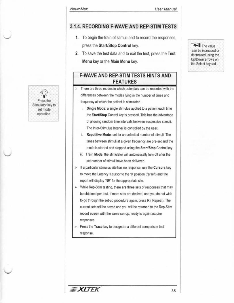
3.1.4. RECORDING F-WAVE AND REP-STIM TESTS
1. To begin the train of stimuli and to record the responses,
press the Start/Stop Control key.
2. To save the test data and to exit the test, press the Test
Menu key or the Main Menu key.
F-WAVE AND REP-STIM TESTS HINTS AND FEATURES
"" There are three modes in which potentials can be recorded with the
differences between the modes lying in the number of times and
frequency at which the patient is stimulated.
i. Single Mode: a single stimulus applied to a patient each time
the Start/Stop Control key is pressed. This has the advantage
of allowing random time intervals between successive stimuli.
The Inter-Stimulus Interval is controlled by the user.
ii. Repetitive Mode: set for an unlimited number of stimuli. The
limes between stimuli at a given frequency are pre-set and the
mode is started and stopped using the Start/Stop Control key.
iii. Train Mode: the stimulator will automatically tum off after the
set number of stimuli have been delivered.
~ If a particular stimulus site has no response, use the Cursors key
to move the Latency 1 cursor to the '0' position (far left) and the
report will display 'NR' for the appropriate site.
;. While Rep-Stim testing, there are three sets of responses that may
be obtained per test. If more sets are desired, and you do not wish
to go through the set-up procedure again, press R ( Repeat). The
current sets will be saved and you will be returned to the Rep-Slim
record screen with the same set-up, ready to again acquire
responses.
;. Press the Trace key to designate a different comparison test
response.
XlTEK 35
~Thevalue can be increased or
decreased using the Up/Down arrows on the Select keypad.

~'()~ l ''f'
To return to the NCS Test Menu, press the Test
L ukey.
I ~-n~ --. ''f'
You can also use the Slim Up/Down
keys on the keyboard to set
levels.
User Manual NeuroMax
3.1.5. SETIING UP AN H-REFLEX TEST
1. Using the Select arrows, select Nerve Conduction
Studies from the Main Menu and then press the Select
key to open the Nerve Conduction Test Menu.
2. In Section 1, choose the appropriate Nerve using the
Select arrows and then press the Select key to continue.
3. In Section 2, choose the H-Reflex Test using the Select
arrows and then press the Select key to continue.
4. In Section 3, choose the side you wish to test and then
press the Select key to open the H-Reflex Test screen.
3.1.6. ACQUIRING H-REFLEX RESPONSES
36
1. To begin the train of stimuli and to acquire responses,
press the Start/Stop Control key.
2. After each successive sweep, increase the stimulation
intensity using the Stirn Up/Down arrows on the Control
keypad.
3. Once the H Wave has been attenuated press the
Start/Stop Control key to stop.
4. Adjust stimulus mode by pressing the Stimulator key, or
make changes to defaults by pressing the Default key on
the keyboard.
XLTEK
: ~r'i I The stimulus intensity may also be controlled by using the Up/Down arrows on the slim probe. See System j Options ln Ch. 8.

:~ l To return to the
Test Menu, press the Test
Menu key.
NeuroMax User Manual
4. ELECTROMYOGRAPHY (EMG) TESTS
This chapter will deal with the operation of the NeuroMax in it's Electromyography Studies mode of operation. The NeuroMax has many views of the data on screen to view single traces, multiple traces in a raster, single traces with multiple triggered sweeps captured, compressed EMG data in the real-time window. The NeuroMax incorporates two triggers that may be adjusted independently. The first trigger is amplitude/slope. The second trigger acts as a discriminator that allows you to look at smaller potentials
The NeuroMax will store the latest ten seconds of an EMG study. You can choose to review it as a compressed EMG or as a real-time display, with a sweep of 5 ms per division. The memory buffer will automatically be cleared after each new test muscle or with a new needle insertion point.
4.1. SETIING UP THE EMG TEST MENU
Before you begin Electromyography Studies, create an active patient to set up the patient information screen and then retum to the Main Menu screen.
The NeuroMax is set to run three EMG test formats: Free Run, Triggered, and Fast Triggered. Sections 4.2 and 4.3 show you how to perform an EMG acquisition and which test to choose.
4.1.1. SETIING UP AN EMG
1. Using the Select arrows, select Electromyography from
the Main Menu and then press the Select key to open
the Electromyography Test Menu.
2. In Section 1, choose the appropriate Muscle or Suite
using the Select arrows and then press the Select key to
continue.
3. In Section 2, choose either the Free Run Test, the
Triggered Test, or the Fast Triggered Test using the
Select arrows and then press the Select key to continue.
XLTEK 37

Adjust the Audio keys before you begin to avoid
excessive volume.
Press the Settings key to review your
Acquisition settings.
User Manual NeuroMax
4. In Section 3, choose the side you wish to test and then
press the Select key to open the Free Run test screen.
Figure 4.1: Free Run Acquisition
4.1.2. ACQUIRING AN EMG
38
1. To start the acquisition, press the Start/Stop Control
key.
2. To choose different gains, use the Up/Down arrows.
3. To end the acquisition, press the Start/Stop Control key.
4. To classify the results or enter comments, press the
Notes key.
5. Use the Select arrows to change the fields and values in
the Notes Box and then press the Select key to record
entry.
6. Press the Test Menu key to select new muscles to test.
7. Repeat Steps 1-5 until you have completed test
requirements.
8. To review the acquisition, see section 4.3 or press the
Main Menu key to exit the test.
- xlTEK
~When you select TEXT entry, press the Select key to record a text note. Ma~mum120 1 characters. _________j

l 0~~ l Operating
instructions are listed at the
bottom of the screen.
NeuroMax User Manual
4.2. FREE RUN EMG FEATURES
4.2.1. REVIEWING FREE RUN EMG
You can review the most recent acquisition you have just completed, monitor an audio portion of the test, and save waveforms.
1. After completing the Notes, press the Trace key to open
the option box at the bottom of the screen.
2. Review is selected as the value, so press the Select key
to review the acquisition.
3. Press the LeftlRight arrows to move the window box
forward or backward.
4. Audio Replay is highlighted. Press the Select key to play
the last 1 0 seconds of audio.
5. Use the Up/Down arrows to select any of the other
options, including the option to save the current sweep.
4.2.2. ANALYZING TURNS AND AMPLITUDE You can analyze Tums and Amplitude while you are acquiring real-time EMG data or after it has been acquired.
1. Press the Select key to perform a Turns and Amplitude
analysis.
2. Press the LeftlRight arrows to move the Analysis
Window.
-~ 3. Press the Trace key to display a Power Spectrum
analysis on the screen.
XLTEK 39

User Manual NeuroMax
4.3. TRIGGERED EMG FEATURES
When setting up the EMG test (see Section 4.1 ), choose Triggered Test. The Triggered EMG program uses one or two triggers to discriminate and capture various motor unit potentials. The first trigger is an amplitude/slope trigger and each EMG sweep which crosses the trigger will be copied to "raster area." The second trigger is an "exclusion" trigger.
4.3.1. ACTIVATING TRIGGERS
40
The NeuroMax is automatically set to Trigger 1. The active trigger levels are shown at the bottom of the left screen. See Figure 4.2.
1. To adjust trigger amplitude levels, press the Trigger
Up/Down Control arrows.
2. To activate Trigger 2, press the Trigger 1,2 Control key.
3. To adjust Trigger 2 amplitude levels, press the Trigger
Up/Down Control arrows.
~XLTEK
~When the Trigger Slope is negative, Trigger 2 (the exclusion trigger) negative value is greater (higher on the screen) than Trigger 1. When trigger slope is positive, Trigger 2 l positive value is
, greater (lower on t~;1 1 screen) than Trigg~

The Up/Down arrows select which of the wavefonns to
highlight.
___J
I ...,
~tJ~ -, ,-
See Ch. 8 for test recall
procedures.
NeuroMax User Manual
4.3.2. SAVING A TEST
1. When a number of rastered traces are on the screen,
press the Select key to save the test.
2. To adjust the number of waveforms to raster, press the
Trace key.
3. To adjust the cursors in the selected and the averaged
waves, press the Cursors key.
4.3.3. ANALYZING AND REVIEWING MOTOR UNITS
1 . Recall the test file from Patient Directory
2. Use Left/Right arrows to highlight (red) box containing
the motor unit to be edited.
3. Press the Cursors key and then use the Left/Right
arrows to move the highlighted (green) cursor.
4. Press the Up/Down arrows to highlight the next cursor.
5. Press the Cursors key to exit the editing cursor mode.
: XLTEK 41
~ You can save either the highlighted or averaged waveform (average of all the rastered waveforms). -

See Ch. 8 for test recall
procedures.
User Manual NeuroMax
4.4. FAST TRIGGERED EMG FEATURES
When setting up the EMG test (see Section 4.1) , choose Fast Triggered Test.
1. Adjust the trigger by pressing the Trigger Up/Down
arrows.
2. Press the Trace key to select the display format options
and the number of sweeps to place in the raster review
area.
3. Press the Up/Down key to choose between Raster and
Superimposed, and then press the Select.
4. Press the UR arrows to choose the number of traces (8,
20, or 50)
5. Press the Trace key to exit.
6. Repeat as necessary to store additional groups.
4.4.1. REVIEWING AND EDITING FAST TRIGGERED TESTS
42
1. Recall the test file from the Patient Directory.
2. To edit stored group, press the Erase key to edit the
potentials you do not wish included in the calculation.
3. Press the Up/Down arrows to select a pair to erase and
then press the Select key to erase.
4. Make another selection using the Up/Down arrows and
continue editing or exit the Erase function.
5. Press the Erase key to exit.
~XLTEK
I l ~ With a patient active, you are prompted to save all the waveforms when the set number of waveforms have been acquired.

NeuroMax User Manual
4.4.2. CALCULATING MCD
When a saved Fast Triggered response is recalled there is a green cursor you can adjust to calculate jitter measurement.
1. Press the Trigger Up/Down Control arrows to move the
cursor vertically.
2. Press the Left/Right arrows to move the cursor
horizontally and the Up/Down arrows to change the
cursor width.
XLTEK 43
~ The width of the cursor determines MCD measurements.
I ~()~ I ' 'j'
To return to the Other Tests Menu, press the
Test Menu key.
NeuroMax User Manual
5. OTHER TESTS
The NeuroMax conducts several other tests, including Evoked Potentials, Blink Reflex, Incremental Stirn, Heart Rate variability, and P 300.
5.1 . OTHER TESTS
Before you select any of the Other Tests, you need to set up the patient information screen to create an active patient file and then return to the Main Menu screen.
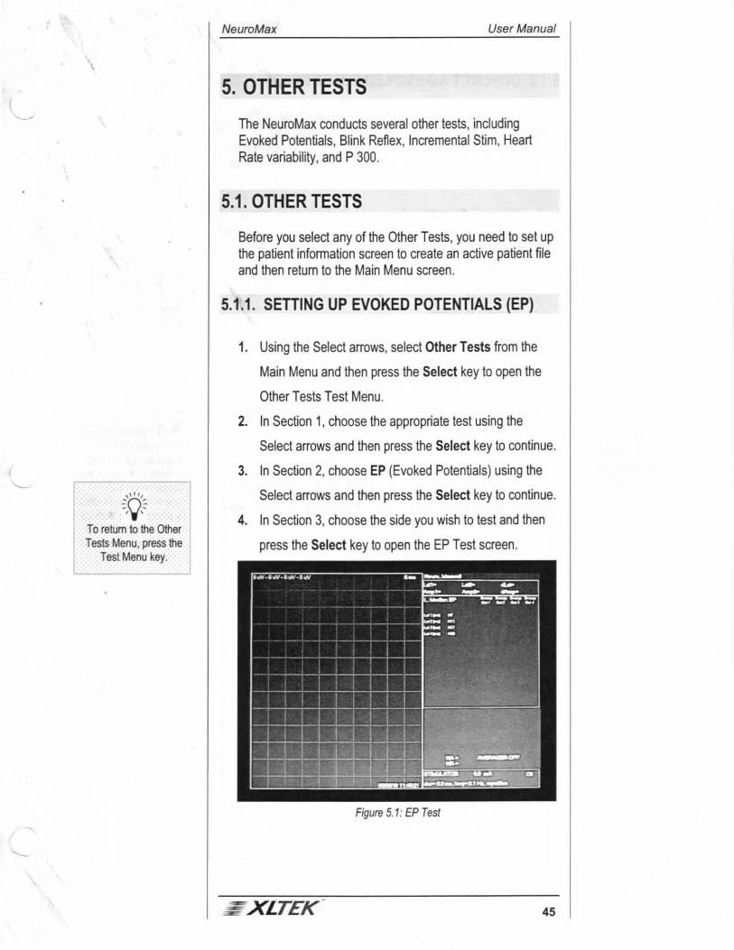
5.1.1 . SEITING UP EVOKED POTENTIALS (EP)
1. Using the Select arrows, select Other Tests from the
Main Menu and then press the Select key to open the
Other Tests Test Menu.
2. In Section 1, choose the appropriate test using the
Select arrows and then press the Select key to continue.
3. In Section 2, choose EP (Evoked Potentials) using the
Select arrows and then press the Select key to continue.
4. In Section 3, choose the side you wish to test and then
press the Select key to open the EP Test screen.
Figure 5.1: EP Test
XLTEK 45

::()'~ -/.._,-Use Select arrows to move cursor and
to select new cursors. See
instructions bottomrich! screen.
User Manual NeuroMax
5.1.2. CONDUCTING EVOKED POTENTIALS
46
The Evoked Potentials test screen is similar to that of the Nerve Conductions. The gains (for all channels) and timebase are shown on the top of the acquisition box and the cursor, data, and stimulator boxes are located to the right of the screen.
1. Press the Start/Stop Control key to begin stimulating.
2. Press the Averager key to begin acquiring data.
3. Once a sufficient number of averages has been
obtained, press the Averager key to begin acquiring the
next set of traces.
4. Once acquisition of signals is completed, press the
Start/Stop Control key to end the stimulation.
5. Press the Cursor key to mark signals.
6. Press the Test Menu key to exit and set up new test or
press the Main Menu key to exit the test.
EVOKED POTENTIALS HINTS AND FEATURES
).. There are two different gains available.
i. Amplifier Gain: the actual input gain of the amplifiers. This
gain influences the rejection level of the signal.
ii. Display Gain: amplifies the signal to better fit the screen. This
second gain does not affect the amplification of the signal; it is
simply for display purposes.
).. If the amplifier gain is set too high, there is a chance that the
amplifier will became exposed to very high amplitude EMG signals.
Thus, since Evoked Potentials are very small magnitude signals,
your may wish to reject more signals than the set 99% of the
amplifier limit. Using A (Acceptance Level), the user can choose
the specific threshold for acceptance/rejection.
~ Choosing Sides
i. Left, Right, or No Side: The EP cursor placement is allocated
by "sweeps." That is, each collection of sweeps is considered
a "set" and cursors are placed accordingly. This option allows
for 4 different sets of up to 4 traces each.
- XLTEK
~You can complete four sweep sets of averages.
~ External Triggers are connected to the NeuroMax via the BNC connector on back panel. Trigger mode and parameters are selected by pressing the Settings key or through Defaults Test Editing page (press Default or the C key).
___j

NeuroMax User Manual
ii. Bilateral: Sets are defined by channel, not by sweep. The first
sweep of channel1 and the second sweep of channel 1 are
considered a set and the data table is filled according to this
new set definition. The bilateral selection (first two sweeps
one side and final two sweeps the other) allows for up to eight
sets of two traces each.
;... There are ten customizable latency cursors, two amplitude, six
inter-peak-interval , distance, and conduction velocity calculations
are also available.
;... Traces may be moved during acquisition by pressing the Trace
key, entering the trace number, and using the Up/ Down arrows to
adjust the trace.
, A single latency cursor is available to you while the traces are
acquiring. Press the Cursors key and then use the Left/Right
arrows.
5.1.3. SEP TESTS
XLTEK 47

User Manual NeuroMax
7. Press the Trace key and then use the
Move/Superimpose features to overlay waveforms.
8. Press the Cursors key to mark signals.
9. To calculate a conduction velocity, press the Distance
key.
10. To exit the test, press the Test Menu key or the Main
Menu key.
5.1.4. SUGGESTED SEP PROTOCOLS
The tables below give you the suggested SEP protocols and the protocols for specific location acquisitions.
SUGGESTED SEP PROTOCOLS
LFF: 20Hz Gain: 20uV/div Avgs:500 HFF: 2kHz Sweep: 5ms/div Stirn Rate: 5.3 Hz
NOTE: SEE CHAPTER 6 FOR THE AV STIM 1000 EP OPERATIONS AND PROCEDURES.
5.1.4.1. MEDIAN C7 TO T1 I ULNAR C8 TO T1 NERVES
Channel C3/4' (-) vs Erb's contra (+)
1
Channel Erb's ipsi (-) vs Erb's contra(+)
2
Channel C3/4' (-) vs Fz (+)
1
Channel C5 (-) vs Fz (+)
2
Channel C3 (-) vs Fz (+)
1
Channel C7 (-) vs Fz (+)
2
48 XLTEK

I '\t' l Wrapping the
stimulated digits in gauze prevents
stimulation spread to adjacent
dermatomes.
NeuroMax User Manual
Channel Erb's (-) vs Fz (+)
3
Channel Elbow(-) vs Fz (+)
4
SUGGESTEDSEPPROTOCOLS
LFF: 20 Hz Gain: 20uV/div Avgs:500 HFF: 2kHz Sweep: 5ms/div Stirn Rate: 5.3 Hz
5.1 .4.2. POSTERIOR TIBIAL NERVE L5 51 52
Channel Cz (-) vs Fz (+)
1
Channel Pop fos ipsi (-) vs Pop fos contra ( +)
2
5.1.4.3. COMMON PERONEAL NERVE 51 52
Channel Cz (-) vs Fz (+)
1
Channel C5 (-) vs L3 (+)
2
5.1.5. DERMATOMAL SEPS
DERMATOMALSEPPROTOCOLS
LFF: 5Hz Stirn Rate: 3.3 Hz HFF: 500Hz Stirn Duration: 0.2 ms
5.1.5.1. MEDIAN DERMATOMAL
C6: Stimulate using ring electrodes places over 1st or 2nd digit, cathode proximal, anode 2cm distal.
Channel Cz (-) vs Fz (+)
1
: XLTEK 49

User Manual NeuroMax
I ~hannel C5 (-) I vs I L3 (+)
5.1 .5.2. ULNAR DERMATOMAL
CB: Stimulate using ring electrodes places over 5th digit, cathode proximal, anode 2cm distal.
Channel C3/4' (-) vs Fz (+)
1
Channel Erb's ipsi (-) vs Erb's contra
2
5.1.5.3. POSTERIOR TIBIAL DERMATOMAL
L5: Stimulate medial side of the 1st metatarsal phalangeal joint with a bar electrode, anode distal.
Channel Cz (-) vs Fz (+)
1
S1 : Stimulate lateral side of the 5th t metatarsal phalangeal joint with a bar electrode, anode distal.
Channel
1 Cz (-) vs Fz (+)
5.1.5.4. SURAL DERMATOMAL
S1 : Stimulate under the lateral malleolus, anode distal.
Channel Cz (-) vs Fz (+)
1
50 - xLTEK

~'0-= l ''f'
To return to the Other Tests
Menu, press the Test Menu key.
There are ten customizable cursors. Six inter-peak-interval calculations are also
available.
NeuroMax User Manual
5.2. BLINK REFLEX
The Blink Reflex test as designed on the NeuroMax is an easy to use protocol for the evaluation of the R1 and R2 Compound Muscle Action Potentials recorded from the orbicularis oculi muscle in response to stimulation of either the supraorbital or infraorbital branch of the trigeminal nerve. The Blink Reflex test allows for the complete examination to be performed on one test screen, with the flexibility in setting up the default configuration to allow you to run your own specific protocol.
5.2.1 . SETTING UP A BLINK REFLEX TEST
1. Using the Select arrows, select Other Tests from the
Main Menu and then press the Select key to open the
Other Tests Test Menu.
2. In Section 1, choose the Facial setting using the Select
arrows and then press the Select key to continue.
3. In Section 2, choose Blink using the Select arrows and
then press the Select key to continue.
4. In Section 3, the Bilateral side is defaulted. Press the
Select key to open the Blink Test screen.
5.2.2. CONDUCTING BLINK REFLEX TESTS
1. Press the Start/Stop Control key to stimulate.
2. Press the Select key to accept waveforms and move to
the other side.
3. Press the Cursors key to mark the signals.
4. Press the Test Menu key or the Main Menu key to exit
the test.
_, XLTEK 51
~The selections for a Blink test are limited by the nature of the test, thus the NeuroMax notifies you i~_the wrong nerve IS
Relected.
~ If you wish to begin on the Right side ( Left is the default), when no waves have been acquired, press the Select key to switch sides.

r ~()~ I ''f'
To return to the Other Tests Menu, press the
Test Menu key.
User Manual NeuroMax
5.3. INCREMENTAL STIMULATION
The incremental stim provides an indication of the relative sizes of the motor units in a muscle, but it can also be employed to estimate the number of the functioning motor units. The muscles which are most suitable for the technique are the EDB (extensor digitorum brevis) and the median innervated thenar muscles, but the technique has also been used routinely for the hypothenar, plantar and bicep muscles. In each stimulation the active recording electrode is a silver chloride strip which is applied across the muscle belly at the level of the innervation zone; a similar surface electrode is positioned over, or beyond the distal tendon and serves as a reference. The stimulating electrodes are placed over the motor nerve or, in some instances, the motor point of the muscle. It is important that the subject rejected.
5.3.1. SETTING UP INCREMENTAL STIMULATION TESTS
1. Using the Select arrows, select Other Tests from the
Main Menu and then press the Select key to open the
Other Tests Test Menu.
2. In Section 1, choose the Nerve/Muscle using the Select
arrows, and then press the Select key to continue.
3. In Section 2, choose I ncr Stirn using the Select arrows
and then press the Select key to continue.
4. In Section 3, choose either the Left or the Right side and
then press the Select key to open the Incremental Stirn
screen.
5.3.2. CONDUCTING INCREMENTAL STIMULATION TESTS
52
1. Press the Start/Stop Control key to begin the
stimulation.
2. Increase the stimulation intensity until a small response
is seen.
3. Press the Select key to save response.
XLTEK

I :;'0:: --"1 ''i'
To return to the Other Tests Menu, press the
Test Menu key.
NeuroMax User Manual
4. Increase the stimulation slowly and save responses
which are different from those on the screen.
5. When ten or more waveforms have been acquired, stop
the repetitive stimulation by pressing the Start/Stop
Control key.
6. Press theM key on the keyboard.
7. Press the Start/Stop Control key to deliver single stimuli.
8. Increase stimulus until response is maximal.
9. Press the Select key to save.
5.4. HEART RATE VARIABILITY (HRV)
The HRV test on the NeuroMax is designed to graph the variability in hear rate over the course of a 60 second time trial. The parameters obtained at the completion of a 60 second trial with the test are: 1. Maximum Heart rate (Max HR)
2. Minimum Heart Tate (Min HR)
3. Mean Heart Rate ()Mean HR)
4. Standard Deviation of the Heart Rate (S.D. HR)
5.4.1. SETTING UP HRV STIMULATION TESTS
1. Using the Select arrows, select Other Tests from the
Main Menu and then press the Select key to open the
Other Tests Test Menu.
2. In Section 1, choose the Nerve/Muscle using the Select
arrows and then press the Select key to continue.
3. In Section 2, choose HRV using the Select arrows and
then press the Select key to continue.
4. In Section 3, the Left side is automatically selected by
the NeuroMax. Press the Select key to continue to the
HRV test screen.
- xlTEK 53
~The Missetup to determine maximal response-gain J changes to SmV/div.

Press the Erase key to delete all or a portion
of the data.
User Manual NeuroMax
5.4.2. CONDUCTING HRV TESTS
The Heart Rate Variability test on the NeuroMax is designed to graph the variability in heart rate over the course of four 60-second time intervals. At the completion of each 60 second time trial , the following parameters are calculated.
HRV TEST PARAMETERS
Maximal Heart Rate Maximal R-R interval Minimal Heart Rate Minimal R-R interval Mean Heart Rate Mean R-R interval Standard Deviation Heart Rate Standard Deviation R-R
interval HRV Ratio (Max HR I Min HR)
1. Set trigger to appropriate level using the Trigger
Up/Down Control arrows.
2. Press the Start/Stop Control key to begin and then
press it again to end the acquisition of data.
3. Press the Select key to save the response and then
move to next graph.
5.4.3. SSR-THE SYMPATHETIC SKIN RESPONSE Involvement of the automatic nervous system recording of the sympathetic skin response is one method of rapid evaluation of the autonomic nervous system. The response is also known as either the galvanic skin response or the electrodermal response. SSR reflects the voltage changes on the skin due to activation of either the palmar or plantar sweat glands in response to a variety of stimulii. In this case, electrical. The SSR is a multi segmental somatosympathetic reflex arc terminating with a final efferent pathway passing through preganglionic and postganglionic sudomotor fibers. Though intimidating to conceptualize, it is straight forward to perform. The patient must be relaxed and recumbent.
54
Normal recording parameter are not consistent through the literature, We suggest that you use variations of the below given parameters. LFF 0.5 to 2.0 Hz, HFF 500 to 5,000 Hz, Gain 500 ~V/div Timebase 1 sec/div
XLTEK
~ Pressihe Cursors key to modify the graph area where the calculations are oerformed.
NeuroMax User Manual
Stimulate single irregular intervals with long interstimulus intervals ... between one (1) to three (3) minutes to avoid habituation. Record from the side contralateral to the site of stimulation.
Hand: Reference electrode placed on the back of the hand, active electrode placed on palm. Stimulate the median nerve at a supramaximallevel 0.1 msec. Cathode is proximal.
Foot: Reference electrode placed on dorsum, active electrode placed on sole. Stimulate the tibial nerve at a supramaximallevel 0.1 msec. Cathode is proximal.
Latencies are measured form the stimulus artifact to the onset of the first negative OR positive peak. Amplitude is measured peak to peak. A typical recording session will consist of collecting up to ten (1 0) responses from each nerve and recording the mean value.
5.5. MULTI-CHANNEL EMG/IOM
1. Press the Stimulator key and then set stim parameters,
including duration, mode, maximum intensity
2. Press the Start/Stop Control key to begin the
acquisition. Press it again to end the acquisition.
3. Press the Space Bar to stimulate or to begin repetitive
mode.
4. Press the Settings key to make changes in settings.
XLTEK 55
~Applies I
to the NeuroMax 1002/1004.
__j

User Manual NeuroMax
5.6. MULTI-CHANNEL NERVE CONDUCTIONS
Choose Other Test Menu Choose or create Nerve Test Name Choose multi-CH NCS Choose side Hit DEFAULT key for Test Defaults Editing Page Customize your settings i.e. what channel is used, what channel is on, test type, gains, timebases, sites etc. Hit SELECT and 'S' to save settings
Example: Median 2CH NCS
Active Ch Channel1 On CV Segments Segmental LFF(Hz) 5.0 HFF(Hz) 2.0k
2 On Total 30 2.0k
Notch Filter Off On Gain (uv/div) Sk . 20 Lat1 take off take off Lat2 _ neg phase Amp _ bsln to peak Rec Site APB Stim Site1 Wrist Stim Site2 Elbow Stim Site3 Axilla Etc ...
peak peak to peak Index Wrist Elbow Axilla
5.7. THE P300 TEST Please Note: This test requires NeuroMax 1004/1002, code version 2.0 (available October '99) or above and an AV Stirn 1000, code version 5.0 (available October '99) or above.
5.7.1. GETTING STARTED
56
From the Main Menu, the P300 test can be accessed from Other Tests (Option 3). Select a Nerve or Muscle, then select P300 and a side. The test will run identically for each side.
The P300 Test screen is similar to that of Evoked Potentials. The gains (for all four channels) and timebase are shown on the top of the acquisition box and the cursor, data and stimulator boxes are located on the right of the screen.
XLTEK
NeuroMax User Manual
The stimulator box shows the two different tones to be presented to evoke the P300 response. Their frequency and weighting can be changed using the STIMULATOR hard key.
The data box contains the active cursors and once placed on a waveform, their values. These cursors can be set and labeled by editing the test's defaults. For the first set of waveforms, cursor data will be placed in Standard Set 1 or Target Set 1 (depending on whether the data was collected from a target or standard response).
The command box shows the current tone that is being presented to the patient as well as the number of traces that are either included in the averages or have been rejected. Different averages are kept for target and standard responses. If the NeuroMax is to keep track of patient input, the command box also shows the number of times the button was pressed during a standard tone (Press on Stand.) and how many targets tones were missed by the patient (Missed Targets).
5.7.2. RUNNING THE TEST Enter a patient name and data by pressing PATIENT INFO while in the Test Menu or Main Menu. Enter the desired settings by pressing STIMULATOR or use DEFAULT to set and save these settings. START/STOP to begin stimulating AVERAGER to begin acquiring data -the response from the standard tone are placed above the response from the target (oddball) tone Once a sufficient number of averages have been obtained, press AVERAGER to begin acquiring next set of traces Once acquisition of signals is completed, press START/STOP to end stimulation Press CURSORS to mark signals Press TEST MENU or MAIN MENU to exit the test The patient response can be monitored using the space bar or the external foot switch. The external foot switch can be connected to the back of the NeuroMax. The type of patient response is set in the ST/MULA TOR menu under Patient Input.
.- XLTEK 57

User Manual NeuroMax
5.7.3. HINTS AND FEATURES
58
There are two different gains available. Amplifier gain is the actual input gain of the amplifiers. This gain influences the rejection level of the signal. Secondly, Display Gain, is used to further amplify the signal to better fit the screen. This second gain does not affect the amplification of the signal; it is simply for display purposes.
Traces may be moved during acquisition by pressing TRACE, entering the trace number and using the UP or DOWN arrow keys.
A single latency cursor is available while the traces are acquiring, by pressing CURSOR, and is moved using LEFT or RIGHT arrow keys.
Two sets of traces can be acquired, for repeatability. The response from the standard tone always appears above the response from the target tone. Separate averages for the standard and target tones are maintained. Cursors can be applied to each group of traces - any combination of 1 0 latencies, 2 amplitudes and 6 inter-peak-intervals up to a maximum of 14. These can be turned on or off and labeled while editing defaults.
The typical response mechanism to a target tone is a finger tap or button press. The NeuroMax can monitor the patient input from a target tone from a button press. Typically, for maximal P300 amplitude, the patient must acknowledge that they have heard a target or odd tone. The patient can either enter their response via a press of the space bar or using the foot switch. The NeuroMax keeps track of how many times a response was entered incorrectly (i.e. the space bar was pressed during a standard tone) and how many target tones were missed. These numbers appear in the command box. If a target tone is presented and an acknowledgement is not made, the response is not included in either the standard or the target average.
The current tone being presented is displayed in the command box. The NeuroMax ensures that a standard tone is always played first and ensures that a target tone is always followed by a standard tone. The type of tone to be played is detennined randomly, based on the weightings assigned to each tone in the STIMULATOR menu.
- xLTEK

NeuroMax User Manual
The volume of the tones cannot be changed while averaging. To ensure that the volume is appropriate, press START/STOP until the tones can be heard. Use the hotkey 'R' to display the raw traces. Once satisfied, acquisition can begin by pressing AVERA GER.
To increase the timebase, use the right and left arrows. Because the P300 event usually occurs 300 msec after the stimulus is presented, a timebase of 50 msec is recommended. The timebase can not be changed if the stim in ON or if there are traces on the screen. Press 'R' to erase the raw traces, ERASE to erase the averaged traces and START/STOP to tum off the stimulator. The timebase is limited by the inter-stim-interval so that acquisition ends before the next tone is presented.
Some recommended settings include: LFF: 0.5 Hz HFF: 30Hz Display Gain: 5 uV/div Timebase: 50 ms Cursors: N1, N2, P2 and P3 lnter-Stim-lnterval: 2 seconds Standard Frequency: 1000 Hz at 80% Target Frequency: 2000Hz at 20%
5.7.4. EXPLANATION OF OPTIONS ST/MULA TOR- Number of Stimuli: The number of different tones presented to the patient. If three tones are being presented, the response from Non-Target tones is not displayed or included in any averages.
STIMULATOR- Patient Input: Indicates if the NeuroMax will keep of patient responses. If so, the patient can acknowledge a target tone with a tap of the space bar or the press of the external foot switch.
STIMULATOR- Standard, Target and Non-Target Frequency: Use the right and left arrows to scroll between the available frequencies (250, 500, 1000, 2000, 4000Hz). Then choose the percentage that this tone should be presented. These percentages must total to 100%.
STIMULATOR- Rise/Fall Time: The number of cycles to be used as the ramp up to the tone.
- xLTEK 59

User Manual NeuroMax
60
STIMULATOR- Duration: The length of the tone, not including the rise/fall time.
STIMULATOR -Inter Stimulus lntetvaf: The time between the presentation of tones. This interval must be long enough such that the tone can be presented cleanly (without cut off) and that the entire trace can be displayed before the presentation of a new tone.
XLTEK

I ~R~ l ''I'
The green power indicator lights up whenAVSnM
1 000 is powered
L on.
_j
Audio Out
LED Goggles
Printer
NeuroMax User Manual
6. AV STIM 1000
The AV Stirn is used with Evoked Potentials and operates with both the NeuroMax 1002 and the NeuroMax 1004, and with subsequent operating systems.
6.1. AV STIM 1000 FRONT PANEL
6.2. AV STIM 1000 REAR PANEL
Figure 6. 1: A V Stirn Rear Panel
Audio Out: Plug in the calibrated headphones supplied with your AV STIM 1 000.
Warning: Only the KOSS Model TD/65 headphones or Telephonic TD50 headphones provided have been approved for use with your AV Stirn. Patient isolation in accordance with EN60601-1 is dependent on the approved parts.
LED Goggles: A triggering port designed to allow use of LED goggles in lieu of a visual stimulator monitor.
Warning~ Only the GRASS Model S10VSEB LED goggles have been approved for use with your AV Stirn. Patient
;EXLTEK 61
~Thered l stimulus indicator blinks on when the NeuroMax powers up and flashes at the set stimulus rate.
CAUTION: Before using the eadphones and goggles, you should inspect them for any physical damage to the casings. If there are any signs of cracking, warping, or other physical damage, DO NOT use the equipment. Notify an XL TEK Customer Service Representative immediately.

The red Stimulus light indicates that
the AV STIM is correctly
configured and initialized.
User Manual NeuroMax
isolation in accordance with EN60601 -1 is dependent on the approved parts.
Printer: An optically isolated printer port.
NeuroMax: The connector port to which the NeuroMax is attached with the supplied cable.
VGA: Standard D-sub video monitor connector. The recommended video monitor is a hospital grade VGA or SVGA monitor.
Warning~ Only equipment approved to IEC950, EN 60601-1 or a similar safety standard may be connected to the "Printer" and "VGA" ports on the AV Stirn 1000. The final system must be configured to meet the requirements for safety of medical systems prescribed by EN 60601-1.
6.3. CONNECTING THE AV STIM 1000
62
1. To perform either an auditory or visual evoked potential,
connect the AV STIM 1 000 to the NeuroMax using the
supplied connector cable.
2. Switch the NeuroMax Off and then insert the male 26-
pin connector of the connector cable into the Printer port
at the rear of the NeuroMax.
3. Insert the other end, also a male 26-pin connector, into
the AV STIM 1 000 NeuroMax port.
4. Tum the NeuroMax On and check the AV STIM 1000 to
confirm that the green light comes on, followed by a brief
flash from the red Stimulus light
- XLTEK

NeuroMax User Manual
6.4. WARNINGS AND CAUTIONS
The following Warnings and Cautions are marked with a
& and must be followed very closely to ensure the safety of both the patient and the user of the AV Stirn and the NeuroMax. It is therefore important to read and observe ALL of the Warnings and Cautions before attempting to use the AV Stirn and the NeuroMax. If there is any malfunction or perceived malfunction of the system, please call an authorized XL TEK service representative immediately at 1-800-387-7516. An authorized XLTEK service representative must only conduct all internal system checks and/or service.
6.4.1. WARNINGS
Warnings MUST be followed when using the equipment. Warnings apply to conditions, which can injure the patient and/or the operator.
WARNING: Exposure to excessive sound can cause temporary and even permanent hearing loss.
WARNING: Long term exposure to excessive light can cause temporary and even permanent changes in visual acuity.
WARNING: Patient electrical isolation (BS EN 60601-1) is ensured when all peripherals (Headphones, Printer, Goggles, Monitor) attached to the Audio Visual Stimulator are XL TEK approved. The final system configuration must meet the requirements of EN 60601 -1 for safety of medical systems.
WARNING: Use of the AV STIM 1000 is not compatible with defibrillators or electrocautery devices.
63

User Manual NeuroMax
6.4.2. CAUTIONS
Cautions must be noted when using the equipment. Cautions apply to conditions which may damage the NeuroMax and other equipment.
CAUTION: If you choose to attach a VGA display other than the model supplied by XL TEK, it MUST either meet IEC 601-1 or the leakage current requirements for your jurisdiction.
CAUTION: The AV STIM 1000 provides signals to the headphones, the LED goggles, and to the video stimulator. Otherwise, signals are provided by the NeuroMax.
6.5. CALl BRA TION AND MAINTENANCE The AV STIM 1000 requires minimal maintenance. The supplied headphones are factory calibrated to the specific NeuroMax you are using. If for any reason, the headphones require replacement or re-calibration, both the headphones and the AV STIM 1000 unit must be returned to XL TEK.
Please observe the following conditions:
l- For the sound level pressure reading to be valid, only XL TEK
approved headphones are to be used.
~ The AV STIM 1000 does not at present support NTSC video
monitors.
:- The visual stimulator must be calibrated by the user. This
involves dedicating a monitor for the purpose of presenting
the visual stimulus, collecting normal values, and then fixing
the brightness, contrast and distance to the patient. Do not
alter these values.
64 - XLTEK

NeuroMax User Manual
,.. The interior surface of the LED goggles should be inspected
before and after an examination, and cleaned with a soft
cloth. Remove any oil or dust from both the interior and
exterior surfaces. Periodically check to be certain that all
LEOs are functioning.
6.6. SUGGESTED AEP PROTOCOLS
SUGGESTED AEP PROTOCOLS
LFF: 150Hz Gain: 2uV/div Pulse Frequency: 11 .1 Hz
HFF: 2.0 Sweep: 1 ms/div kHz
Channel A 1 (-) vs Cz (+)
1
Channel A2 (-) vs Cz (+)
2
6.6.1. AEP IMPEDANCE CHECK 1. Press the I (Impedance) key while testing to check
impedance levels.
2. Press the Select key to return to test screen.
: XLTEK 65
~The use of a jumper cable is recommended to connect the reference leads. Also, use electrode to Fz as a ground.

User Manual NeuroMax
6.7. SUGGESTED VEP PROTOCOLS
SUGGESTEDVEPPROTOCOLS
LFF: 0.5 Hz Gain: 5uV/Div Pulse Frequency: 1.1 Hz
HFF: 100 Sweep: kHz 25ms/div
One Channel
I Channel I 1
Oz (-) I VS I Cz (+)
Two Channel Channel
01 (-) vs Cz (+) 1
Channel 02 (-) vs Cz (+)
2
6.7.1. VEP IMPEDANCE CHECK
66
1. Press the I (Impedance) key while testing to check
impedance levels.
2. Set impedance levels.
3. Press the Select key to return to test screen.
-xLTEK~
~The use of a jumper cable is recommended to connect the reference leads. Also, use an electrode to Fz as a ground.
~ Impedances of abou1 5 kOhms are recommended for clear results.

~r;.~ -, ,-
In a unilateral study, 4 sets of 2 channels can be collected in
this manner.
NeuroMax User Manual
6.8. ACQUIRING A FULLFIELD VEP RESPONSE
The setup for the Fullfield VEP Response is completed in the Choose Side section of the Other Tests test screen.
1. Choose the eye to test. To begin with the left eye,
choose the Left side and then press the Select key to
continue.
2. Press the Stimulator Control key and then set the
Stimulator to Left Field Stimulus and/or Right Field
Stimulus.
3. Have the test subject cover the right eye and fixate
towards the center of the checkerboard field with the left
eye.
4. Press the Start/Stop Control key and begin the
acquisition.
5. Press the Averager key to begin averaging.
6. Once a set is completed, press the Averager key again
to collect the next set.
7. To test the Right side, press the Test Menu key, select
the Right side in the Choose Side section of the Test
Screen, and then press the Select key to continue.
8. Cover left eye and repeat steps 2-6.
67
~ lfyouare doing a Bilateral test, start with the left eye and follow the steps.
~ lfyouare 1
doing a Bilateral test (collecting waveforms on the same menu screen), switch eyes and repeat steps 3-6~

~R: I ''W'
Use these tables to set your Montage
levels. L _j
User Manual NeuroMax
6.9. ACQUIRING A HEMIFIELD VEP RESPONSE
68
The setup for the Hemifield VEP Response is completed in the Choose Side section of the Other Tests test screen.
1. In the Choose Side section, select Bilateral and then
press the Select key to continue.
2. Press the Stimulator key and set the Stimulator to Left
Field Stimulus and Right Field Nothing.
Montage for Right eye (left covered)
Channel Oz (-) vs Fpz (+)
1
Channel 1 Ocm lateral to 01 vs Fpz (+)
2 (-)
Montage for Left eye (Right covered)
Channel Oz (-) vs Fpz (+)
1
Channel 1 Ocm lateral to 02 vs Fpz (+)
2 (-)
3. Have subject cover the Right eye and fixate towards the
center of the checkerboard field .
4. Press the Start/Stop Control key and begin acquisition.
5. Press the Averager key to begin averaging.
6. Once a set is completed, press the Averager key again
to collect the next set.
XLTEK
XLTEK.
~To switch to the other side, cover the left eye, set the Stimulator to Right Field Stimulus and Left Field Nothing.
-

::()-: '"f'
The Default key is located at the
bottom left of the keyboard.
NeuroMax User Manual
7. SETTING THE DEFAULTS
The setting on all of your tests can be designed to suit your particular needs. Thus whenever you activate the NeuroMax to do a particular test, your specific settings will already be chosen. This automatic setting is called a "default setting," and the NeuroMax comes to you with a full complement of default settings designed to meet the greatest variety of requirements.
7.1. TEST MENU PARAMETERS
On any given test menu you can change/add the name of a nerve (Nerve Conductions Test Menu), muscle (Electromyography Test Menu), or protocol (Other Tests Menu).
CAUTION: This will permanently change the Test Menu.
1. From the NeuroMax Main Menu screen, use the Select
arrows to choose the Test Menu and then press the
Select key to open the Test Menu.
2. Use the left/Right arrows to place the yellow highlight
over the position to be changed.
3. Press the Default key to open the Default Settings box.
4. Using the keypad, enter the name of the new nerve/
muscle/ protocol.
5. Press the Select key to exit.
7.1.1. CREATING AN ELECTROMYOGRAPHY SUITE
You can set the default parameters to create a personalized EMG suite that fits your specifications.
1. From the NeuroMax Main Menu, use the Select arrows
to choose Electromyography and then press the
Select key.
: XLTEK 69
~You can also activate the Default setting box by pressing Backspace +C.
--·_j

User Manual NeuroMax
2. Use the Left/Right arrows to place the yellow highlight
over the Suite name you wish to edit.
I ~ 3. Press the Default key.
~ You can also
''Q' ' ' 4. Using the keypad, enter the name of the Suite. activate the Default
The Default key is 5. Press the Select key to save the name of your Suite. setting box by pressing Backspace
located at the +C. bottom left of the 6. Use the Left/Right arrows to place the yellow highlight
keyboard. over the next muscle you wish to add to the suite and _J
then press the Select key. Continue until all muscles
have been added.
7. Press the Test Menu key twice to save and exit.
7.2. EDITING TEST DEFAULTS
Many of the test routines and features of the NeuroMax, including test protocols and other functions, are customizable to allow automation of many routines. The NeuroMax1 002/1004 is equipped with factory default settings for many tests, and these are a good general guide for many of the tests and reporting features. However, you may wish to change these settings. If the changes desired are temporary, then the changes should be made using the various keys (Settings, Stimulator). However, if you want the new settings to be automatically included each time a particular test is selected, then the defaults should be changed.
1. From the NeuroMax Main Menu screen, use the Select
arrows to choose the test menu and then press the
Select key.
2. Using the Select arrows, choose the test you wish
change and then press the Select key twice to open the
Active Test Screen. .....---
~ 'Q~ 3. Press the Default key. ~ You can also -, ,-activate the Default
The Default key 1s 4. Use the Select arrows to choose the settings to change
setting box by located at the and then use the keyboard to enter the new values. pressing Space Bar
bottom left of the +C. keyboard.
_j These values become the new default settings.
70

NeuroMax User Manual
5. Press the Select key to open the Save and Exit dialog
box.
Press S to save, or D to discard changes. To restore factory defaults, press R. To continue editing defaults, press E.
Figure 7. 1: Save and Exit Dialog Box
6. Select one of the options and continue. Note that you
can always return to the factory default settings that
came with the NeuroMax.
XLTEK
= XlTEK 71

NeuroMax User Manual
8. ADMINISTRATIVE FUNCTIONS
The NeuroMax Administrative Functions are designed to help you customize the NeuroMax and to manage the information acquired by the tests.
This chapter shows you how to customize reports, store data, and transfer files.
8.1. ADMINISTRATIVE FUNCTIONS
The Administrative Functions menu allows you to customize the reports, functions, and memory of the system. Data entered on these menus makes permanent changes to the system. The following chart lists the administrative functions.
REPORT FUNCTIONS
Patient Directory Recall, print, and edit stored patient files
Memory Delete files and erase memory Management Batch Print Print all non-printed reports System Options Set global options including date,
time, units of measure, printer type, artifact rejection, external stimulator, and more
Edit Report Format Edit macros, select fields included in the report, and report layout
Edit Site Name List Edit the available default stimulation sites
Edit EMG Notepad Edit available notes for scoring EMG Edit Patient Info. Edit the field definitions for the Fields Patient Info screen Save File to Disk NeuroMax saves patient files to
floppy disk as "read onlt Archiver files, and a s such can only be read by Archiver
8.1.1. PATIENT DIRECTORY
The patient directory may be quite extensive because the NeuroMax has the ability to store many files.
~XLTEK 73

User Manual NeuroMax
Figure 8. 1: Patient Directory It outlines which patients are saved on the system, the status of those patients (Printed, Not Printed, Transferred), the date the patients were saved and gives the user certain functions.
PATIENT DIRECTORY FUNCTIONS
Patient Callback Recall a patient to add to the current file or to begin a new study.
Test Directory View list of test files, along with the date and time they were performed. Within this directory, tests can be recalled and then edited or deleted.
Print Report Print the highlighted patient report. View Report View the highlighted patient report. Edit Patient Info. Edit the selected patient
information. Connect To PC Connect NeuroMax to a PC to
download files. Print All Test Print all performed test waveforms Screens in condensed format. Print Letter Print the history and interpretation in
a letter format with the referring doctor's name.
Save File to Disk Moves highlighted files to floppy disk. See section 8.1.2. for details.
Exit Directory Exit to Administration Menu.
8.1 .2. MEMORY MANAGEMENT
74
The Memory Management Option shows you the available memory and how to clear the memory to allow for more patient files. You should monitor the memory on the
XLTEK
~Make l sure you select the patient file before activating the Function options. ______j

NeuroMax User Manual
NeuroMax regularly and archive the reports you wish to store.
Figure 8.2: Memory Management
IMPORTANT: Deleting patient files from the NeuroMax moves the information from live file memory, which is shown as a yellow bar, to deleted file memory, which is shown as a red bar. Both types of file memory will increase to fill the total maximum amount of memory available. To free up more memory on the NeuroMax you must archive/backup all deleted files by: 1. Saving the files to another computer via floppy and Archiver or 2. By printing hard copies of the files. Once you have backed up all the files use these steps to permanently delete the deleted files and free more memory. TAKE NOTE THAT THE PERMANENT DELETION OF FILES PERTAINS TO ALL DELETED FILES OR NONE OF THE DELETED FILES.
1. Start in the Main Menu
2. Select Administrative Functions #4
3. Select Memory Management #2
4. Select Delete All Files #2
E XLTEK 75

User Manual NeuroMax
8.1.3. BATCH PRINT
Batch Print collects and prints all the patient files that have not yet been printed or that have not yet been transferred to Archiver.
8.1.4. SYSTEM OPTIONS
Using the System Options allows you to set a variety of standards for display formats and printed reports. You can also enhance the NeuroMax's performance.
Figure 8.3: System Options
8.1.5. EDIT REPORT FORMAT
76
You can design the report formats to fit your particular requirements. The NeuroMax provides five areas to customize.
i) _Edit Report Header: Places name, address, and other information on all reports .
ii) Edit Interpretation Macros: Provides titles for automatic notes use in history and interpretation fields.
iii) Turn on/off Report Fields: Selects the fields to be printed in the tables of the report.
iv) Change Report layout: Edits the report format to sort by time, test name, and Muscle or nerve.
v) Return To Administration Menu: Returns you to the main administration menu.
= XLTEK

NeuroMax User Manual
8.1.6. EDIT SITE NAME LIST
You can change or add the default stimulation site names by selecting an existing name and then deleting and entering a new name.
8.1.7. EDIT EMG NOTEPAD
You can edit the standard Notes format available when acquiring EMGs to reflect your requirements.
8.1.8. EDIT PATIENT INFORMATION FIELDS
You can customize the fields you would like to appear on the patient information section of the reports.
8.1.9. CHANGING THE DATE ON STORED OAT A
On Pre-stored Files
1. Tum On the NeuroMax, or be certain that there is currently no selected patient.
2. From the Main Menu, select Administration Functions then Patient Directory
3. Choose the Patient Choose 0. Patient Callback into Current Study
4. Choose Main Menu followed by Administration Functions followed by SYSTEMS OPTIONS
5. You are now going to change the date to suite your needs. 6. Choose Edit Date or Edit Time and set to the required
needs. 7. Exit from this screen, go to Main Menu and press Patient
info. And choose Edit Current Patient. 8. You must now rename the patient. I suggest that you
simply add aaa to the beginning of the patient name. 9. Press Patient Info. When done. 10. Patient is now stored under the new date. 11 . You must now press Patient Info. again and remove the
aaa from the patient name. Press Patient info. To exit this screen
12. Repeat steps 4 to 6 to change the date back to the current date.
13. You are now complete.
- xlTEK 77
~The new name cannot be more than 12 characters long.

Click the Browse button to find new folder or type new
folder into test field.
User Manual NeuroMax
8.2. ARCHIVER
Archiver is a program designed to help you store and manage your NeuroMax data files on a separate computer, leaving the NeuroMax for further acquisitions.
There are two steps you need to complete before you can begin the process of transferring your data files to a computer. First you need to install the Archiver program onto the host computer you will be using, and second, you need to transfer the files from the NeuroMax to the computer.
8.2.1. INSTALLING ARCHIVER ON A COMPUTER
78
1. Insert disk into the A: drive.
2. Click Start in the Windows taskbar and then click Run to
open the Run dialog box.
3. Type a:\Archiver_32 in the text field and then click the
OK button to open the Archiver installation dialog box.
AlchrveJ_32
chiver_32 by EJcel Tech Lid
ro::l.-e;!Cd tr1 PliCk<IQef-orllt<:Web'" V1 31 rnNRurtr. ... v
IIJ"'I~ 1 • lm!ll.,.,. ~ld tt'MH~ apor!\Drr J ''lrfiS re•ene<l
Figure 8.4: Archiver Installation
4. Click the Next button to begin opening the files.
5. Select a destination folder for the Unzipped (unpacked)
files. The default folder chosen for you is
c:\Excel_ Tech\lnstall .
6. Click the Finish button to continue and click the Yes
button to create the directory.
~ Get the latest version of Archiver from our Web site: http://www.xltek.com.
~ Archiver is a Windows 95/98/NT program. Make sure to install on proper operating system. j
~ If you wish to remove previous versions of Archiver, click Yes to All to overwrite existing files.

r- ::o~ ''f'
You can remove the disk at this point
NeuroMax User Manual
7. When the Installation Wizard Welcome dialog box
opens, press the Next button to continue.
8. Read the next two text boxes and if you agree with the
text statements, click the Yes buttons to continue.
9. Type in your Name, Company, and the required Serial
#: and then click the Next button to continue.
1 0. Archiver asks you once more to confirm the folder
destination. Click the Next button to continue.
11. The computer will have to be shut down and restarted
before you can run Archiver. Select a shut down option
and click the Finish button.
8.2.2. STARTING ARCHIVER
1. Double-click the Archiver icon on your desktop.
2. Once in the Archiver screen, click Options on the Menu
bar and then select Set Directory. Click the Browse
button and look for the directory that you created as your
default patient directory.
8.2.3. TRANSFERRING NEUROMAX FILES TO A PC
There are two ways to transfer files from the NeuroMax to a PC.
i) _Manual Disk Transfer: Copy the files to a disk in the NeuroMax disk drive and then load onto the PC.
ii) Serial and Parallel Port Transfer: Connect the NeuroMax to a PC using the Serial or Parallel Port connector cable and transfer the files.
8.2.3.1. MANUAL DISK TRANSFER
1. From the NeuroMax Main screen, select Administrative
Functions and then press the Select key.
2. Choose Patient Directory and then press the Select
key.
: XLTEK 79
~ Use Windows Explorer to cr~ate a folder to store the archived patient files if the software does not automatically . J
create one for yo~

User Manual NeuroMax
3. Choose the patient file to be transferred, press the -...
Select key, and then choose Function #9, Save File to \,_.,
Diskette.
4. After the file has been saved to disk, transfer the disk to
the PC and insert into the A: drive.
5. Read files from Archiver. (See Section 8.3.2.)
'f)' I - --, ,-8.2.3.2. SERJAUPARALLEL PORT TRANSFER ~ lfyouare
If there are connection setting up Archiver for problems, shut down With the serial/parallel port cable connection, you can the first time, click both units, reattach
transfer files directly from the NeuroMax to the PC. The first Options, click the cables, tum the Communications, and NeuroMax on, and thing you need to do is attach the cable. select a port. ((Parallel
then tum the PC on. port for Parallel Able or 1. Connect the NeuroMax to the PC with the supplied cable Com 1 for Serial
by attaching the small end into the NeuroMax printer Cable).
port and the large end into the PC's parallel port (usually
LPT1).
2. Double-click the Archiver icon on your PC desktop to
open the program and then click File on the Menu bar.
I ~r;~ 3. Click Connect to NeuroMax and then comply with the -1 ,-
If there are connection on-screen instructions asking that NeuroMax be
problems and are switched off and then turned on again. using a laptop PC, do
NOT use battery 4. Press the Report key on the NeuroMax to display a list power but plug the
of all patients in the NeuroMax directory on the PC ~You can select laptop directly into a wall unit. files for transfer in two
_j screen. ways: 1) Press Select
5. Using the PC keyboard, highlight the file(s) you would All. 2) Select the first file then toggle down your
like to transfer from the NeuroMax. list to the last file while ~r;~ holding down the Shift -, ,- 6. To transfer multiple files, depress the Ctrl key on your key. All files between
If there are connection these two will be problems, select a PC keyboard while selecting your files to transfer. selected.
different printer driver 7. Select Transfer on the Archiver File Menu bar to for the PC. We suggest the HP320 or transfer the files from the NeuroMax to the PC.
the HP340. 8. To transfer just one file, double right-click it, or click it
once and then click Transfer.
80

I ~'()~ ''W'
The patient file names are composed of the first 8 characters of the patient's name.
NeuroMax User Manual
9. To exit the NeuroMax Directory Screen on the PC, click
File on the Menu bar, and then click Close.
8.3. MANAGING THE REPORTS
Once you have transferred the reports from the NeuroMax to your PC, you can view them, print them, edit them, and/or discard them. Transferring the files by cable also changes their format into Rich Text Format (RTF), which can be read by a variety of word processing programs.
8.3.1. RICH TEXT FILES (RTF)
Downloading files to a PC by cable will automatically create files with an RTF file extension in the default directory. If modifications are made on an Archiver file, it must then be transferred to RTF format.
1. Open the file to be exported.
2. Choose Save As from the File menu.
3. Choose Rich Text Format for the file type and press the
OK button. A file ending in the .rtf extension is created.
4. Open this file using the word processor of your choice.
Consult the documentation on your word processor for
more information on importing files in Rich Text Format.
8.3.2. VIEWING PATIENT REPORTS
There are two ways to open a patient report file to view.
1. From Archiver, click File on the Menu bar and click
Local Patient Directory to bring a list of all the patient
files on the PC onto the screen.
2. Double-click the patient file to view.
OR
1. From Archiver, click File on the Menu bar, click Open,
and then click on a patient file.
: XLTEK 81
~ You can decide how you want to manage the files, whether you want to use them or periodically delete them.
~The file name extension is '.dOO' for new files. Each time a file on the NeuroMax is modified and transferred to a PC, the file extension number incrementally increases by one.

You can also open a section by pressing the Enter key or by double- clicking the
section to edil
User Manual NeuroMax
8.3.3. PRINTING PATIENT REPORTS
1. From Archiver, open the file to print.
2. Click File on the Menu bar, select Print or Print
Preview from the File menu, and then click the OK
button.
8.3.4. EDITING PATIENT REPORTS
Files are edited using the insertion cursor, the flashing vertical bar positioned at the first line of a report section at the left of your screen.
1. From Archiver, open the file and position the insertion
point at the top of the section you want to edit.
2. In the Section menu, click Open to open a data box and
a waveform window for modifying the section.
3. Change cursor positions by dragging the desired cursor,
or by selecting it and using the arrow keys to move it to
a new position.
4. Click the OK button to accept the modifications or click
the Cancel button to discard the changes.
5. Click File on the Menu bar and then click Save or Save
As from the File menu to save the changes.
8.3.5. EDITING FAST TRIGGERED STUDIES
82
1. To modify the trigger line, go to the waveform screen for
the study and select Superimpose from the Trace
menu to make the trigger line visible.
2. Select the trigger line and use the mouse or arrow keys
to move it, or use Shift + arrow keys to grow or shrink
the trigger line.
XLTEK
~Movethe insertion cursor using the arrow keys or the mouse.
~When! opening a bilateral table for modification, you are prompted to choose either the left or the right side. To skip this, hold the Ctrl key when opening the table to jump directly to the left side. Similarly, hold the Shift key down to jump to the right side.
~Twoother ways to move the trigger line: 1) use the mouse or arrow keys. 2) Use the Shift + arrow keys to grow or shrink the trigger I inA

- ~'fi~ I , ... ,
If Integrate Waveforms is checked, the wavefonns are
integrated, otherwise they are displayed at the end of the report.
NeuroMax User Manual
8.3.6. PRINTING THE WAVEFORMS IN ARCHIVER
There are three ways to approach the editing and printing of waveforms in Archiver.
8.3.6.1. FIRST: PRINT SCREEN
1. Double-click a NCV test with the left mouse button to
open both the waveforms and the results table.
2. Click on a waveform to make the cursors active.
This is simply an editing screen and won't be printed unless you press Print Screen on your keyboard and import the image into a bitmap imaging program such as Paint.
8.3.6.2. SECOND: REMOVING OR DISPLAYING WAVEFORMS
Removing
1. To remove the waveforms of a particular test from the
printed report during a test, select the test.
2. Click Section and then click Hide Waveforms.
Displaying
1. To display the waveforms of a particular test from the
printed report during a test, select the test.
2. Click Show Waveforms to display a particular
waveform.
XlTEK 83

Modify allows you to choose
which variable is displayed in all test modalities.
User Manual NeuroMax
8.3.6.3. THIRD: PERMANENT WAVEFORMS
84
This useful setting turns on the waveforms permanently.
1. Open a patient file and then click Option on the Menu
bar.
2. Click Style and then click New to access the options
which will define the way that your screens will appear.
3. Select New and type in the name of this style.
You can create and an unlimited number of styles; however, one must be set as the default style while the other styles may be applied to a specific patient for specific reasons.
4. Click the OK button and then select Modify.
5. Click the arrow next to General to select the other
options.
6. Select MNC to show a list of options and then click
Show Waveforms to tum it on.
7. Click the OK button and then select Modify again to
repeat the process for the other tests you want this
waveforms to appear in.
8. Once you have finished modifying the tests, click Set
Default to select this style as your default.
XLTEK
XLTEK
~You l can modify your Header on the left of the new screen. On the right of the screen, the General option determines how your date will appear and if the waveforms are integrated (appear associated with the results table). _j

NeuroMax User Manual
9. APPENDIX 1: WARRANTIES
9.1. WARRANTY INFORMATION
The warranty duration of your XL TEK NeuroMax and associated components is as follows:
NeuroMax1 002 /1004 AV Stimulator Medical Cart, Convenience Arm Headbox, 3 Button Stimulator Optical isolator Accessories
3 years 1 year 1 year 1 year 1 year 30 days
9.1.1. NEUROMAX WARRANTY SERVICE
Warranty service consists of the following:
• Hardware Service • Clinical Support Service
* See XL TEK Warranty Definitions listed below for a full description of the services provided during the warranty period.
The terms and conditions of your warranty of XLTEK REALPATIENT installation are the following:
9.2. EXTENT OF LIMITED WARRANTY
XL TEK warrants to the end-user customer that XL TEK products will be free from defects in materials and workmanship, for a specified time after the date of receipt by the customer. The duration of this limited warranty is as stated above. XL TEK does not warranty the operation of any product to be uninterrupted or error free. XLTEK does not extend this warranty to any third party owners or users of the product. Warranties are voided on re-sold units.
XL TEK limited warranty covers only those defects which arise as a result of normal use of the product, and do not apply if the product has been subjected to:
• Improper or inadequate maintenance • Software or interfacing not supplied by XL TEK • Unauthorized modification or misuse • Improper site preparation or maintenance
XLTEK 85

User Manual NeuroMax
A particular XL TEK component may be void of warranty with accompanying charges such as repair or replacement costs, shipping charges, travel and accommodations costs, etc. being billed to the customer. Whereby XL TEK equipment that has been repaired or replaced because of apparent defective hardware components, and it is evident that the device has been subject to damage due to reasons stated above, the customer will then be billed for all costs associated with its repair or replacement.
If XLTEK receives, during the applicable warranty period, notice of a defect in the product which is covered by XL TEK warranty, XLTEK shall either repair or replace the product, at its option, with a product that may be new or like-new, provided that it has functionality at least equal to that of the product being replaced. All correspondence with XLTEK must specify both the model name and/or serial number, as it appears on the product.
9.3. LIMITATIONS OF WARRANTY
XLTEK (nor any of its third party suppliers) does not make any other warranties of any kind, whether expressed or implied with respect to XL TEK products. XL TEK and its third party suppliers specifically disclaim the implied warranties of merchantability and fitness for a particular purpose. To the extent that this Limited Warranty Statement is inconsistent with the law of the locality where the customer uses the XLTEK product, this Limited Warranty Statement shall be deemed modified to be consistent with such local law. Under such local law, certain limitations of this Limited Warranty Statement may not apply to the customer.
To the extent allowed by local law, the remedies provided in this Limited Warranty Statement are the customer's sole and exclusive remedies.
9.4. LIMITATIONS OF LIABILITY
Except for the obligations specifically set forth in this warranty statement, in no event shall XLTEK be liable for any direct, indirect, special, incidental, or consequential damages, whether based on contract, tort, or any other legal theory and whether advised of the possibility of such damages.
XL TEK will make all reasonable efforts to satisfy the customer's needs in terms of providing a temporary replacement unit for an inadequately functioning XL TEK unit. XL TEK does not assume any responsibility for loss of income due to such an event. It is the customer's responsibility to manage their own patient data base (i.e.: printing or downloading patient files to a computer).
9.5. EXTENDED WARRANTY INFORMATION
86
The following services can be purchased in addition to the warranty provided with the purchase of XL TEK equipment, software and services. These items are at no time offered unless otherwise clearly purchased, with a signed quotation or purchase order, and full payment forwarded to XL TEK. Prices are available through your sales representative or an XLTEK Inside Sales Representative.
XLTEK

NeuroMax User Manual
9.6. NEUROMAX MAINTENANCE SERVICE
NeuroMax Maintenance Service consists of: • Hardware Service • Clinical Support Service
9.7. 24 HR REPLACEMENT GUARANTEE
Includes an on-site loaner guarantee for the duration of the warranty period for any XL TEK acquisition component (price per acquisition component)
9.8. PRICING
Warranty pricing is based on the list pricing of a customer's XL TEK installation excluding the cost of training, installation, and discounting. The warranty packages are priced as a percentage of the total list pricing of their hardware.
9.9. XL TEK WARRANTY DEFINITIONS
9.9.1. HARDWARE SERVICE.
XL TEK shall use commercially reasonable efforts to repair or replace defective hardware components of the Equipment within 48 hours of reported failure. XL TEK agrees to provide substitute equipment, where available, to enable the client to carry out normal business activity until a repair has been effected. At XL TEK 's option, a defective component is replaced: (i) By XL TEK; or (ii) By forwarding a replacement component to Customer for installation with XL TEK telephone assistance. Replacement parts will be new or reconditioned to perform as new. Replaced parts become the property of XL TEK. XLTEK is not responsible for replacing accessories or consumables including Needles Electrodes or Recording media.
9.9.2. CLINICAL SUPPORT SERVICE.
XLTEK shall provide telephone support, 5 days a week, 12 hours a day for consultation in solving Equipment Problems. Telephone Support Service is not for employee training and Customer shall regulate staff use. XL TEK shall be obligated to provide a response to an inquiry as soon as is practically possible
X lTEK 87
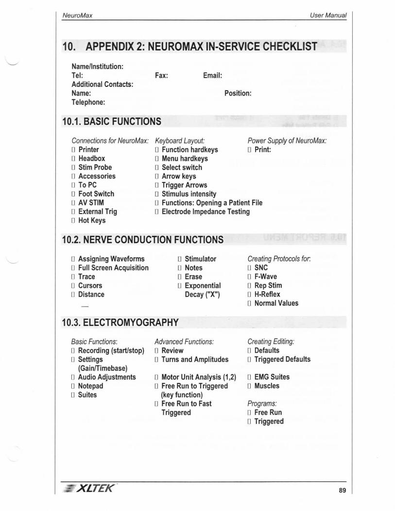
NeuroMax User Manual
10. APPENDIX 2: NEUROMAX IN-SERVICE CHECKLIST
Name/1 nstitution: Tel: Fax: Email: Additional Contacts: Name: Position: Telephone:
1 0.1. BASIC FUNCTIONS
Connections for NeuroMax: D Printer D Headbox 0 Stirn Probe 0 Accessories D To PC D Foot Switch D AVSTIM o External Trig 0 Hot Keys
Keyboard Layout: Power Supply of NeuroMax: D Function hardkeys 0 Print: 0 Menu hardkeys 0 Select switch o Arrow keys D Trigger Arrows 0 Stimulus intensity 0 Functions: Opening a Patient File 0 Electrode Impedance Testing
1 0.2. NERVE CONDUCTION FUNCTIONS
0 Assigning Waveforms 0 Full Screen Acquisition 0 Trace 0 Cursors 0 Distance
0 Stimulator o Notes 0 Erase 0 Exponential
Decay ("X")
1 0.3. ELECTROMYOGRAPHY
Basic Functions: 0 Recording (start/stop) 0 Settings
(Gain/Timebase) 0 Audio Adjustments 0 Notepad 0 Suites
: XLTEK
Advanced Functions: n Review 0 Turns and Amplitudes
o Motor Unit Analysis (1 ,2) 0 Free Run to Triggered
(key function) 0 Free Run to Fast
Triggered
Creating Protocols for. o SNC 0 F-Wave o Rep Stirn 0 H-Reflex 0 Normal Values
Creating Editing: 0 Defaults 0 Triggered Defaults
0 EMG Suites 0 Muscles
Programs: 0 Free Run 0 Triggered
89

User Manual NeuroMax
1 0.4. ADMINISTRATIVE FUNCTIONS
Patient Directory: 0 Search Utility 0 Patient Callback 0 Test Directory n Print Report 0 View Report u Delete File 0 Edit Patient Info o Connect to PC 0 Print Test Screens
Memory Management: 0 Pack Flash 0 Patient Directory 0 Delete all Files 0 Delete all printed files
0 Batch Print:
System Options: 0 1) Report Format o Report Header 0 Interpretation Macros 0 2) Site Name List 0 3) EMG Notepad 0 4) Patient Information
Fields
1 0.5. DUAL CHANNEL TESTS
Functions: 0 EP's - Stimulating 0 Averaging D Saving Waveforms 0 Cursors
0 BLINKS • Stimulating 0 Saving Waveforms 0 Cursors 0 HRV
0 Creating Protocols for EP's 0 Multi Channel EMG/IOM 0 Multi Channel NCS
1 0.6. REPORT MENU
While in an active patient file, press REPORT. The following functions should now be available: U View Report 0 Print Report 0 Print Report and Waveforms n Interpretation
0 Edit Report (host directory) 0 Save Current Patient to
Diskette
1 0. 7. ACCESSORIES
90
Main Contact( for ordering Consumable items): Name: Phone:
Please indicate style currently used U Disposable Monopolar
0 Disposable Concentric 0 Disposable lnjectible Monopolar
Please indicate the length and gauge of the needles used: _ __ _ Please indicate the number of EMG's performed monthly: _ __ _ Please indicate if you are using: Please indicate current Accessories Supplier: 0 Disposable Electrodes fro NCS 0 Reusable Electrodes for NCS
Are you currently receiving Preferential Pricing for a Needle Contract? 0 YES 0 NO
Would you be interested in hearing how XL TEK Accessories are able to enhance the quality of your studies, as well as save you time and money? o YES o NO
XLTEK

NeuroMax
1 0.8. CONFIRMTION
Date Completed:
Client Name:
(please print)
Client Name:
(please sign)
XlTEK
User Manual
Sales Rep:
(please print)
Sales Rep:
(please sign)
91

NeuroMax User Manual
11. APPENDIX 3: TROUBLESHOOTING/MAINTENANCE
Here you will find information on how to work through trouble spots during the operation of the NeuroMax. If you cannot solve the problem, keep notes on the event so that you can explain them clearly to an XL TEK service technician.
If you continue to experience any difficulties in either the set-up or everyday use of your system, please contact XL TEK Customer Service:
Toll Free: 1-800-387-7516 Direct: (905) 829-5300 Fax: (905) 829-5304
11.1. SOFTWARE
The following sections show you how to verify the software version on your machine, how to update your software, and how to install NeuroMax Loader.
11.1.1. CHECKING SOFTWARE VERSION ON NEUROMAX
1. Tum on the power to the NeuroMax.
2. From the Main Menu screen, press Shift and the V key on the keyboard.
3. The version number appears in the bottom-left comer of the screen.
11.1.2. UPDATING SOFTWARE
1. Obtain the newest version of software from either the XL TEK Web site (http://www.xltek.com)
or from head office. Call Customer Service at 1-800-387-7516.
2. Ensure that you have a PC (Windows 95, 98, or NT) with Windows Explorer running, the PC
download cable, your NeuroMax, and the software.
3. Place the disk into the PC floppy disk drive. Open Windows Explorer and then click the 3Yz
inch floppy (A: ) icon in the left window.
4. The contents of the disk will appear in the right window. Select the executable file (.exe) and
double-click the icon.
5. A screen opens asking you to Unzip four files. Choose UNZIP and in a few seconds a
message appears confirming that four files have been successfully Unzipped. Click the OK
button to continue.
6. Follow the instructions asking you to tum off the NeuroMax.
XLTEK 93
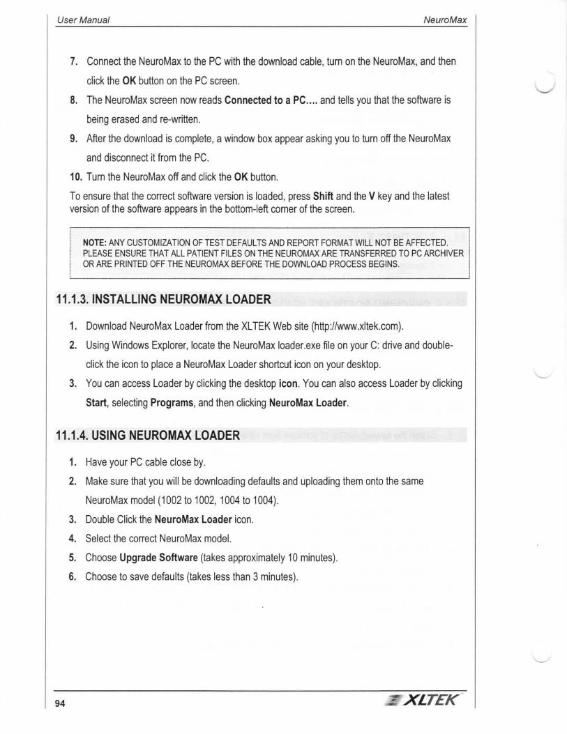
User Manual NeuroMax
7. Connect the NeuroMax to the PC with the download cable, tum on the NeuroMax, and then
click the OK button on the PC screen.
8. The NeuroMax screen now reads Connected to a PC .... and tells you that the software is
being erased and re-written.
9. After the download is complete, a window box appear asking you to tum off the NeuroMax
and disconnect it from the PC.
10. Tum the NeuroMax off and click the OK button.
To ensure that the correct software version is loaded, press Shift and the V key and the latest version of the software appears in the bottom-left corner of the screen.
NOTE: ANY CUSTOMIZATION OF TEST DEFAULTS AND REPORT FORMAT WILL NOT BE AFFECTED. PLEASE ENSURE THAT ALL PATIENT FILES ON THE NEUROMAX ARE TRANSFERRED TO PC ARCHIVER OR ARE PRINTED OFF THE NEUROMAX BEFORE THE DOWNLOAD PROCESS BEGINS.
11.1.3. INSTALLING NEUROMAX LOADER
1. Download NeuroMax Loader from the XL TEK Web site (http://www.xltek.com).
2. Using Windows Explorer, locate the NeuroMax loader.exe file on your C: drive and double
click the icon to place a NeuroMax Loader shortcut icon on your desktop.
3. You can access Loader by clicking the desktop icon. You can also access Loader by clicking
Start, selecting Programs, and then clicking NeuroMax Loader.
11.1.4. USING NEUROMAX LOADER
1. Have your PC cable close by.
2. Make sure that you will be downloading defaults and uploading them onto the same
NeuroMax model (1002 to 1002, 1004 to 1004).
3. Double Click the NeuroMax Loader icon.
4. Select the correct NeuroMax model.
5. Choose Upgrade Software (takes approximately 10 minutes).
6. Choose to save defaults (takes less than 3 minutes).
94 - XlTEK

NeuroMax User Manual
11.2. NERVE CONDUCTIONS
This section gives you the basic steps for creating a Nerve Conduction Study (NCS), how to edit it, and how to set up a stimulus site.
11.2.1. CREATING A NCS
1. From the Main Menu screen, select Nerve Conduction Studies.
2. Find a blank position and press Backspace and C. Edit new name and press Select to save.
Now choose new nerve name, choose test, and choose side to go to acquisition screen.
11.2.2. EDITING AN NCS
1. From a NCS Acquisition Screen, press Backspace and C simultaneously (or press the gray
Default key on the keyboard) to open the Test Defaults Editing screen.
2. In this screen you can customize the amplifiers, gains, filters, and timebase by using the
Up/Down arrows to move through the list and the Left/Right arrows to toggle through the
options.
11.2.3. SETTING UP STIMULUS AND RECORDING SITES
1. In the Test Defaults Editing screen, use the Down arrow to highlight Reference Site and
press R to designate the reference site as Recording or press S for Stimulation.
2. Press the Down arrow to highlight Site 1. The Site Name List appears in the top-right of the
screen.
3. Use the Right and Left arrows to select the site name you want and then press the down
Arrow to continue.
4. Press the Down arrow to move down the next site and repeat step 3.
NOTE: IF THE SITE YOU NEED IS NOT IN THE SITE NAME LIST. GO TO~HE MAl~ MENU SCREEN AND l SELECT ADMINISTRATIVE OPTIONS. SELECT EDIT SITE NAME LIST, FIND A BLANK POSITION, AND
l THEN ENTE~-TH~-R~QUIRED SITE NAME. --- -- __ j
5. To enter normal values, highlight Normal Values and toggle through latency, amplitude, CV
and distance using the Down arrow and enter the normal values that you have established in
your lab.
Once finished, press the Select key and then press S to save the changes.
XLTEK 95

User Manual NeuroMax
11.3. ELECTROMYOGRAPHY
This section gives you the basic steps for creating an electromyography suite and how to use it.
11.3.1. CREATING AN ELECTROMYOGRAPHY SUITE
1. Decide ahead of time the order of the muscles you want to have in the EMG Suite and make
sure that they are in the EMG site name list.
2. From the Main Menu screen, select Electromyography and press the Select key.
3. From the Electromyography Test Menu select the Suite that you wish to rename and then
press the C key.
4. Use the keyboard to enter the name of the Suite (e.g. upper limb) and then press the Select
key to save the Suite name.
5. When the Suite Column appears, use the Select arrows to highlight the first muscle in the list
and then press the Select key to save highlighted name.
6. Move to the next muscle in the Suite to select and repeat.
7. Press the Test Menu key to save and exit Suite creation.
11.3.2. USING AN ELECTROMYOGRAPHY SUITE
96
1. From the Main Menu screen, select Electromyography and press the Select key.
2. Select the Suite you want, the type of EMG test, and then the side.
3. The Suite name list appears in the active screen. Press the Start/Stop Control key to start
recording from the highlighted muscle.
4. When you are ready to move to the next muscle, press the Test Menu key to highlight the
next muscle or use the Up/Down arrows to move to the muscle you want to test. Once
highlighted, press the Start/Stop Control key to begin recording.
5. When finished, press the Test Menu key to exit.
XLTEK

NeuroMax User Manual
11.4. ADMINISTRATIVE FUNCTIONS
The administrative functions are designed to help you prepare the NeuroMax for your specific circumstances and to manage the data you have acquired once the testing is complete.
11.4.1. EDITING STUDIES
11.4.1 .1. EDITING A PATIENT STUDY WHILE IN ACTIVE PATIENT FILE
1. From Main Menu screen, press the Report key.
2. In the Function column, choose Edit Report.
11 .4.1.2. EDITING A PATIENT STUDY NOT IN ACTIVE PATIENT FILE
1. From Main Menu screen, select Administrative Functions and then select Patient
Directory.
2. Using the Select arrows, choose Patient Directory, highlight patient name, and then select
Test Directory in the Functions column.
3. Choose the test to edit and press the Select key, choose Recall and Edit File.
11.4.2. INTERPRETATION MACROS
11.4.2.1. CREATING A MACRO
1. From the Main Menu screen, select Administrative Functions and then select Edit Report
Format.
2. From the Edit Report Format Menu, select Edit Interpretation Macros to view the 30 titles
that can be edited. Each title represents one interpretation macro.
3. To edit a title, choose it using the Select arrows. A red cursor appears in the lower box. Next
use the keyboard to enter your prepared macro into the highlighted position and then press
the Select key to enter the macro.
4. When finished, press the Select key once to move onto the next macro.
5. To exit from the Edit Interpretation Macros screen, highlight EXIT from Interpretation
Macros and press the Select key.
XLTEK 97
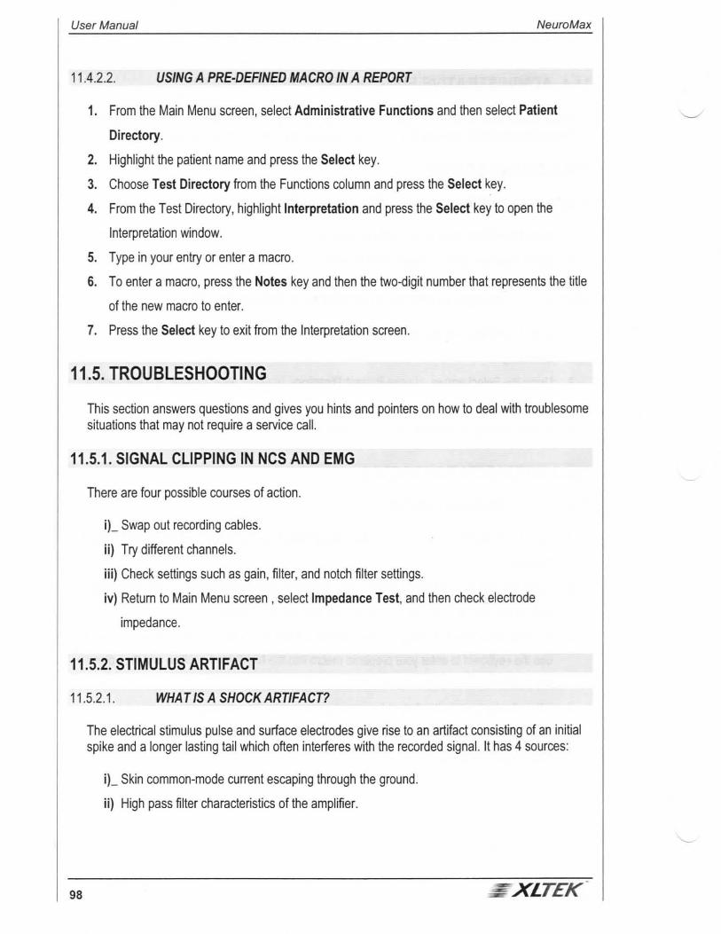
User Manual NeuroMax
11.4.2.2. USING A PRE-DEFINED MACRO IN A REPORT
1. From the Main Menu screen, select Administrative Functions and then select Patient
Directory.
2. Highlight the patient name and press the Select key.
3. Choose Test Directory from the Functions column and press the Select key.
4. From the Test Directory, highlight Interpretation and press the Select key to open the
Interpretation window.
5. Type in your entry or enter a macro.
6. To enter a macro, press the Notes key and then the two-digit number that represents the title
of the new macro to enter.
7. Press the Select key to exit from the Interpretation screen.
11.5. TROUBLESHOOTING
This section answers questions and gives you hints and pointers on how to deal with troublesome situations that may not require a service call.
11.5.1. SIGNAL CLIPPING IN NCS AND EMG
There are four possible courses of action.
i)_ Swap out recording cables.
ii) Try different channels.
iii) Check settings such as gain, filter, and notch filter settings.
iv) Return to Main Menu screen , select Impedance Test, and then check electrode
impedance.
11.5.2. STIMULUS ARTIFACT
11 .5.2.1. WHAT IS A SHOCK ARTIFACT?
98
The electrical stimulus pulse and surface electrodes give rise to an artifact consisting of an initial spike and a longer lasting tail which often interferes with the recorded signal. It has 4 sources:
i)_ Skin common-mode current escaping through the ground.
ii) High pass filter characteristics of the amplifier.
~ XLTEK

NeuroMax User Manual
iii) Voltage gradient between the recording electrodes caused by a stimulus current flowing
through the limb.
iv) Capacitance coupling between recording and stimulus leads.
The NeuroMax takes care of the first two variables. You can check the following:
i) Properly connect the patient to the NeuroMax.
ii) Provide a good ground between the stimulator and recording electrodes in order to tie the
floating potential of the patient's limb to the machines' ground.
iii) Reduce the skin to electrode impedances to reduce common mode voltages, artifacts and
50/60Hz interference.
iv) Avoid crossing stimulator and recording cables to eliminate induced currents.
v) Keep skin dry between electrodes to prevent bridging of the electrodes.
11.5.3. ELECTRODE IMPEDANCE
NOTE: It is important to keep electrode impedance low and balanced.
Electrode impedance should be kept below 1 Ok (green range) for the best results in recording low amplitude signals (<50uV peak to peak). Higher impedance allows the incursion of power line interference (60Hz or 50Hz) and shock artifacts. Both of these phenomena can obscure your short latency sensory response. At these impedance levels, it becomes necessary to turn on your notch filter. Impedance greater than 1 OOK red level with sensory responses below 100 uV peak to peak are invariably difficult to interpret.
Unbalanced electrode impedance will produce a specific shock artifact. If the Reference electrode (+)is larger than the Active electrode(-), the shock artifact will start from above the baseline and sweep down. Similarly, if reversed, the shock artifact will start from below the baseline and sweep upwards.
11.5.4. SKIN PREPARATION
NOTE: It is important to work with a clean skin surface.
The skin is a living tissue. As such it is made of various layers. The top three layers are of crucial importance as they are highly nonconductive. The three layers are the actual dermis, the dead covering of dry scaly dead skin, and a layer of oils, sebum, and dirt.
: XLTEK 99

User Manual NeuroMax
Normal SNAPs require no skin preparation. Clients who have callused, greasy, dirty, or dry skin require an extra effort on the part of the Physician/Technologist to obtain good results. Typically washing the skin area of interest (both recording and stimulus sites) with warm soapy water is adequate. For more difficult sites or where washing is difficult or inappropriate, rubbing with of an alcohol swab may be more efficacious. Remember, you are removing these three layers so use of gentle force may be required. We recommend the use of a mild abrasive such as Omni-Prep (pumice suspended in a mild detergent), the hard end of a Q-tip, or rough tissue paper for more difficult situations.
HAZARD WARNING: Rubbing the skin may expose you to blood borne diseases. It is your responsibility to protect yourself and the patient from any contact with blood borne diseases. Please take appropriate care.
11.5.5. ELECTRODE TYPE AND PLACEMENT
Proper electrode to skin connection is vital when attempting to perform a surface recording.
11 .5.5.1. GROUND ELECTRODE
As a general rule, the larger the better. We recommend a stainless steel electrode with a surface area of at least 5cm2 (0.75 inch2). A few drops of a conductive paste should be applied to the skin and the ground plate pressed on top of this. It may be held in place with a piece of tape. Another common solution is the use of a large disposable self adhesive, pre-gelled electrode. Place the ground BETWEEN the stimulator and the recording electrodes.
11 .5.5.2. RECORDING ELECTRODES
Please be consistent. Always use the same type of electrodes for active and reference, otherwise your results may not be consistent.
The most common type of electrodes are either metal discs (with conductive paste) or disposable self-adhesive electrodes. Both are usually about 0.5 to 3 cm2 in area (0.1 to 0.5 inch2).
The Active electrode (Black- Cathode) is to be placed over the nerve towards the cathode of the stimulator. The Reference electrode (Red+ Anode) is placed 2 to 3cm (distance is set by your procedure) distal to the active electrode (relative to the cathode of the stimulator), again over the nerve. Make sure that the skin surface between all 3 electrodes is dry. In addition, stainless steel clip type electrodes with conductive paste may be used.
We do not recommend the use of steel coil electrodes for recordings if you are unfamiliar with their use. Slipping the coils onto the digit will disperse the gel between the two electrodes, usually causing an electrode bridge and subsequent shorting between the electrodes. Also, using spring coils or spring electrodes can increase the surface area and also disperse the signal since part of the surface area is over a silent area of the digit. Stimulus artifact may be reduced in these situations by covering the segment of the clip that is not over the nerve with a piece of gauze or tissue paper.
100 XLTEK

NeuroMax User Manual
r NOTE: YOU WILL ONLY PIC~ UP A SNAP IF YOUR RECORDING ELECTRODES ARE PLACED OVER TH~ CORRECT NERVE. BE AWARE OF ANOMALOUS INNERVATIONS.
- --- -
11.5.6. STIMULATOR
Though the NeuroMax can stimulate well by simply pressing the stimulator prongs against the skin, if the message Stimulator impedance high appears on the screen you will be required to add a small drop of conducting gel to the stimulator prongs. Do not spread the gel otherwise the current will spread over a larger skin area, effectively diminishing the current under the prongs forcing you to increase the applied current and causing stimulus artifact problems.
11 .5.6.1. PATIENT COMFORT
NOTE: A relaxed patient is your friend.
Keep the stimulus current to "just the right amount." Excessive current causes the patient to feel pain and the NeuroMax to pick up excessive stimulus artifact. Furthermore, tense patients contract their muscles and inject EMG activity into the sensory recording. This will make your NCV look very rough making correct interpretation impossible.
HINT: IF YOU SUSPE~T T~ T THE ~SCLE B~NEA TH YOUR ELEC~RODES IS TEN~E~R~ TO-- --1 OBSERVE THIS WITH EITHER A FREE RUNNING SURFACE EMG OR BY INCREASING THE SPEAKER VOLUME. USE THIS TO HELP RELAX THE PATIENT. I
11.5.6.2. HOW TO STIMULATE
NOTE: Slow and steady.
The amount of current is determined by slowly increasing the stimulus intensity until the SNAP appears. Continue to increase the current until the amplitude of the response ceases to increase. If the patient is obese, has hard, dry skin or has a neuropathy, then you will have to increase the current beyond normal limits. Remember, increasing the current will cause the current to spread and to be shunted in unpredictable ways almost always leading to the formation of a shock artifact.
11 .5.6.3. LEAD WIRES
NOTE: Reduce induced currents.
With individual unshielded recording lead wires, the best results are achieved when the active and reference lead wires are of the same length and are loosely twisted together up to the point where they have to branch off to reach the electrode placements. They should be kept away from other cables and from the unit's enclosure to minimize interference from power lines and other external sources.
XlTEK 101

User Manual NeuroMax
Similarly, when stimulating with two individual cables from the NeuroMax Stirn Probe, those wires should also be twisted together and kept away from recording lead wires. This will ensure no increase in stimulus artifact due to coupling between cables.
In environments with high interference levels, better SNAPs are recorded if you use the NeuroMax shielded acquisition cable. This cable takes advantage of NeuroMax's unique active differential shield drivers producing efficient shielding without compromising on common mode rejection and signal bandwidth. This cable plugs into the 5 pin DIN connector on the headbox and provides alligator clips for active, reference and ground electrodes.
XL TEK's design differs from other manufacturer's shielded recording cables that do not support differential shield driving technology and instead rely on simply grounding their shields. Cables of this type add common mode capacitance to the input lines causing degradation of high frequency common mode rejection which in tum causes an increase in stimulus artifact and an increased susceptibility to high frequency interference. Depending upon cable length, signal bandwidth may also be compromised. Such cables may reduce power line interference at the expense of an increase in stimulus shock artifact, increased high frequency interference, and reduced bandwidth.
11 .5.6.4. WHEN ALL ELSE FAILS
Sometimes the obvious solutions is the right one. When all else fails, check the following:
1. Check your impedance. Keep both low and relatively even.
HINT: IF BOTH ARE EXACTLY THE SAME, SUSPECT A FAULTY GROUND. UNPLUG THE GROUND, IMPEDANCES SHOULD RISE. IF THEY DO NOT, CHANGE THE GROUND CABLE.
2. Try running a surface EMG with the volume on. The EMG acts as an oscilloscope, if there is
noise in the system, you may be able to spot it here.
3. Unplug any other devices on the same circuit such as printers, mechanical beds, vacuum
cleaners, or other potential sources of leakage current.
4. A medical grade ground should be installed in your clinic. Some clinics do not have properly
grounded electrical systems.
5. If the patient is tense, ask her to relax.
6. Frequent inspections of your cables will help prevent recording problems.
7. Always have a backup acquisition cable and a backup ground.
8. Are any of the electrodes touching? If so, they are causing a short circuit and you will develop
an artifact.
9. Try pressing X on the keyboard to mathematically remove the shock artifact from the
waveform in the acquisition screen.
102 XlTEK

NeuroMax User Manual
10. Rotate the anode around the cathode. This might shunt the shock artifact away from the
recording electrodes.
11. Increase or decrease the pulse duration of the stimulus.
12. Average the sensory response.
11.5.6.5. REDUCING ELECTRODE IMPEDANCE
1. Use an alcohol prep pad to swab the skin to remove any excess sweat or lotion.
2. Use a mild abrasive paste or pumice tape and gently rub the skin over the stimulation site to
remove dead skin and then swab with the alcohol pad.
3. Instruct patients ahead of time to avoid applying lotion to the skin on the morning prior to their
test.
4. Make sure that the sticky electrodes are adhering properly to the skin. If they have become
loose, replace them with new ones.
5. Make sure that the Stirn probe has some gel on the tips and that there is not gel all over the
patient's skin causing a bridge.
6. Make sure that the patient is properly grounded--good sticky electrode, wet Velcro ground
strap, and good connections in the headbox.
7. When in doubt, try another channel.
11.6. AV STIM
1. Attach the short cable between the NeuroMax and the AV Stirn and then turn on the power to
the NeuroMax. The NeuroMax recognizes the AV Stirn.
2. When the power is turned on, the green power light on the AV Stirn lights up and the red
stimulus light flashes once confirming the initialization of the AV Stirn with the NeuroMax.
3. If you are having problems printing, check the other inputs to the AV Stirn (printer, VGA
monitor, headphones).
4. If a printer is hooked up to the AV Stirn but is not plugged into an outlet, power will drain from
the NeuroMax and prevent the acquisition of BAERs and VEPs. Disconnect the printer.
XLTEK 103

User Manual NeuroMax
11.7. PRINTING
If you are having printing problems, try the following:
11.7.1. NEUROMAX
1. Shut down NeuroMax and printer and then disconnect all cables.
2. Reconnect all cables, tum on the printer, and then turn on NeuroMax.
3. From the Main Menu screen, select Administrative Studies and then select Patient
Directory.
4. Select the patient file and then select Print Report.
11.7.2. PRINTER
,_ Try individual test print from the printer itself by disconnecting from NeuroMax and holding
down the paper feed and power button.
, Swap out printer cable and or Opto cable.
,. Does the printer need a new toner cartridge?
,. Download files to Archiver and print direct from PC to printer.
11.8. PREVENTATIVE MAINTENANCE
Following a regular schedule of preventive maintenance will help to prolong the lifespan of the NeuroMax. Regular preventive maintenance does not involve access to the interior of the NeuroMax; for service problems that require corrective maintenance and/or internal component service, please call the Excel Tech Service department at 1-800-387-7516, or contact your local Excel Tech representative.
Preventive maintenance involves regular inspection and cleaning of all system components, including the NeuroMax enclosure, keypad, Screen, back panel and connectors, headbox and headbox cable, stimulus probe and cable, printer and printer cable and all electrodes and accessories:
Being an extremely portable system, the NeuroMax will probably be subject to increased daily wear and tear as compared to previous, larger EMG systems; this fact has been a very conscious part of the design of all aspects of the NeuroMax and its performance. That being said, taking basic care of the system by avoiding extreme physical contact will help prolong the lifespan of the NeuroMax.
104 XlTEK.

NeuroMax User Manual
CAUTION: DISCONNECT THE POWER CORD FROM THE SYSTEM AND THE WALL BEFORE CLEANING. USE A LINTFREE CLOTH. DO NOT USE ABRASIVE CLEANERS ON ANY SYSTEM COMPONENT( SEE ENCLOSURE BELOW).
Be careful not to allow any excess fluid to seep into the internal electronic components of the system; be especially careful around the grills located both on the front panel near the top (i.e. the speaker grill) and on the left side of the NeuroMax near the back, as well as around the back panel connections and the headphone jack on the right side near the front.
11.8.1. NEUROMAX ENCLOSURE
The NeuroMax enclosure can be cleaned with a damp cloth, using water, mild detergent or cold sterilizing agent. As above, be careful to avoid allowing excess fluid to seep into any internal components. Since the enclosure is manufactured using a high-grade aluminum metal, there should be no cracks in the case itself; periodic inspection of the enclosure mounting screws is only required to ensure that the screws are not coming loose.
11.8.2. KEYPAD
The keypad should be cleaned with a damp cloth (water or mild detergent) only. Do not use any commercial cleaning products, as they may react with the rubber composition of the keypad. Closely inspect the individual keys on a regular basis to ensure no cracks have occurred. Avoiding any sustained exposure to extreme temperatures (above 50° Celsius or below -20° Celsius) will help prolong the integrity of the keypad.
11.8.3. SCREEN
The screen itself is protected with a front cover made from a mylar-type material, however the screen uses glass internally, so care should be exercised not to drop or bump the screen, as this may cause the glass to crack or break. The screen can be cleaned in the same fashion as the keypad, by wiping with a damp cloth with no water dripping off or a mild detergent, though a soft lint-free cloth is recommended for cleaning the screen.
11.8.4. BACK PANEUCONNECTORS
The back panel of the NeuroMax contains the headbox connector, the printer connector, the AC power cord connector and the Power ON/OFF switch (and fuses). The panel itself is made of a heavy grade, reinforced fiberglass material; avoid any excessive physical stress on the panel itself or any of its components. Check regularly for any cracks that may have developed in the panel; contact Excel Tech service if you suspect any physical damage to the back panel.
- xlTEK 105

User Manual NeuroMax
CAUTION: DO NOT LEAVE ANY CABLES CONNECTED TO THE BACK PANEL WHEN TRANSPORTING THE NEUROMAX; DOING SO MAY CAUSE THE CONNECTORS TO COME LOOSE, AND/OR MALFUNCTION. THE BACK PANEL AND CONNECTORS SHOULD ONLY BE CLEANED WITH A DRY, SOFT, LINT-FREE CLOTH.
11.8.5. HEADBOX AND CABLE
The headbox should only be cleaned with a dry, soft, lint-free cloth. Check regularly to see if any of the electrode connections have become loose; if so, contact Excel Tech service. The head box itself is a completely passive electronic device, but care should still be taken to avoid extreme physical stress to the headbox. Check periodically to determine cable integrity.
DO NOT LEAVE THE HEADBOX ATIACHED TO THE NEUROMAX WHEN TRANSPORTING THE UNIT.
11.8.6. STIMULUS PROBE AND CABLE
The stimulus probe body and cable can be cleaned with a soft, lint-free cloth or a damp cloth soaked in water, mild detergent, or a cold sterilizing agent. Determine cable integrity regularly. The stimulus probe headpieces can be cleaned in the same fashion as the body, but extra care should be taken to remove all electrode gels or pastes that have been used on the headpieces; avoid any long term build-up of gels or pastes on the stimulus probe headpieces, as this may interfere with the optimal performance of the stimulus probe. If the various headpieces do not fit snugly into the probe body, replace them immediately to ensure optimal performance.
11.8.7. PRINTER AND CABLE
The NeuroMax must be used with a IEC 601-1 + A1:1991 + A2: 1995\EN60601-1.03.96 printer. The printer is attached via a standard printer cable to an Opto Isolator cable which then connects to the NeuroMax through the 25 pin printer port.
DO NOT LEAVE THE PRINTER ATIACHED TO THE NEUROMAX WHEN TRANSPORTING THE UNIT.
11.8.8. ELECTRODES AND ACCESSORIES
Regularly clean all surface electrodes and accessories with warm, soapy water or liquid sterilizing agents; ensure that all gels and/or pastes are removed from the electrodes and their cables. Follow the electrode manufacturers' instructions for cleaning and/or sterilizing all electrodes and accessories.
While the NeuroMax has been carefully designed and manufactured to be as reliable and durable as possible, regular cleaning and inspection of system components can only help the long term trouble-free operation of the system. As with other types of medical instrumentation, try to avoid
106 _,_ XLTEK

NeuroMax User Manual
extremes of physical stress (i.e. dropping the unit, etc ... ) and sustained exposure to extreme temperatures. If you suspect any problem that might impact on the safety or effectiveness of the NeuroMax, call Excel Tech service at 1-800-387-7516, or your local Excel Tech representative.
11.9. USER ADJUSTMENTS
If you experience any trouble operating the NeuroMax, it is possible that many of the problems may be overcome through simple user adjustments. This chapter offers a few suggestions designed to overcome some of the more commonly found difficulties; if you experience any trouble that is not described in this section, or if the suggestions here do not correct the difficulty you are having, please call Excel Tech Ltd. or your local Excel Tech Representative for service.
11.9.1. NO ELECTRICAL STIMULUS
The patient does not feel the stimulus pulse, or does not respond to any pulse as expected. The stimulus probe or stimulating electrodes connected to the probe do not deliver any electrical stimulus. Check the following:
1. Check the lower right comer of the screen, in the stimulator status area, to see that the "STIMULATOR ON" message is displayed. If the display reads "OFF", press the START/STOP switch once to activate the stimulator.
2. Check the stimulator status area to determine that the intensity level, in mA, is appropriately set for the current test.
3. Check the connection between the stimulator probe cable and the headbox to ensure that the fit is snug.
4. Check the connection between the headbox and the NeuroMax (at the back on the lower right side of the NeuroMax to ensure that the head box is properly connected - be sure to tighten the thumbscrews so that the headbox cable does not come loose.
5. Check that the skin between the two stimulating electrodes (i.e. anode and cathode) is clean and free from any layer of conducting gel or paste that might create a bridge between the anode and cathode.
6. Press MAIN MENU to exit to the main menu, and then re-enter the current test to reset all software and hardware settings for the stimulus.
7. Check that the "Stimulator Impedance High" error message does not appear when you attempt to stimulate. If it does, clean the stimulus site on the skin and prepare the site with some type of abrasion (e.g. Omni-Prep) to decrease the impedance level.
XlTEK 107

User Manual NeuroMax
11.9.2. NO RESPONSE FROM PATIENT ELECTRODES
A. in NCS or EMG Mode - The acquired waveforms are flat, do not appear, or do not appear correct (or as expected). Check the following:
1. Make sure that the patient electrodes are connected to the correct amplifier channel in the headbox. In all test modes, the screen will display the currently active channel beside the test name in the data table area; check that the active channel corresponds to where the patient electrodes are connected in the headbox.
2. Check that the patient electrodes fit properly into the headbox (not loosely), and also check that there are no apparent breaks in the patient electrode cables.
3. Check the patient electrode impedance levels - if the impedance levels are too high, you may need to replace the electrode, electrode cable, or simply re-prep the recording site on the skin. Make sure that the positive and negative recording electrode sites have similar impedance values.
4. Check the connection between the headbox and the NeuroMax to make sure that it is tight.
5. Check the screen gain and timebase settings to ensure that they are appropriate for the current test. You may also want to check the LFF, HFF, and Notch Filter settings, as well as any sweep or trigger delays being used.
6. Press MAIN MENU to exit to the main menu, and then re-enter the current test to reset all software and hardware settings for the amplifiers
B. in Dual Channel Mode, check for all of the above situations, and then check the following:
1. If the current test calls for averaging, check that the "AVERAGER ON" message is displayed on the screen. If it is not shown, press the AVERAGER hardkey.
2. If the AVERAGER is "ON", check the raw data display to ensure that appropriate data is actually being acquired through the amplifiers (Press space bar to display raw data). If the raw data display is flat, then no data is being acquired by the amplifier(s).
11.9.3. LARGE STIMULUS ARTIFACT
There appears to be an excessively large stimulus artifact at the beginning of each triggered waveform; this can occur in any NCS or Dual Channel test, and may cover up the actual waveform of interest. Check the following:
1. Check the patient electrode impedance levels - if the impedance levels are too high, you may need to replace the electrode, electrode cable, or simply re-prep the recording site on the skin. Make sure that the positive and negative recording electrode sites have similar impedance values.
108 XLTEK

NeuroMax User Manual
2. Check the integrity of the ground electrode cable. If it appears broken or bent at all , try replacing it.
3. Position the ground electrode between the stimulating electrode (or probe) and the active recording electrode.
4. If you are using a non-disposable, metal ground electrode plate, check that there is no corrosion or build up of gel on either the surface of the plate or the contact between the plate and the cable.
5. Check that the amplifier gain setting is appropriate for the current test. It is possible that you may be over-amplifying the signal being recorded, and thus over amplifying the stimulus artifact.
6. If you are using single shot stimulus mode, or even if you are using train mode with a low number of pulses per train, try using AVERAGED acquisition (i.e. press the AVERAGER hardkey to tum on the Averager) to reduce the influence of the variable "noise" of the Stimulus artifact.
11.9.4. NOISY OAT A
The data being displayed on the screen seems excessively noisy. Check the following:
1. Make sure that the patient electrodes are connected to the correct amplifier channel in the headbox. In all test modes, the screen will display the currently active channel beside the test name in the data table area; check that the active channel corresponds to where the patient electrodes are connected in the headbox.
2. Check that the patient electrodes fit properly into the headbox (not loosely), and also check that there are no apparent breaks in the patient electrode cables.
3. Check the patient electrode impedance levels - if the impedance levels are too high, you may need to replace the electrode, electrode cable, or simply re-prep the recording site on the skin. Make sure that the positive and negative recording electrode sites have similar impedance values.
4. Check the connection between the headbox and the NeuroMax to make sure that it is tight.
5. If everything appears prepared and set up as it should be and there still appears to be noise in the data being acquired, try using the other acquisition channel. To switch acquisition channels, put the active and reference recording electrode cables (or the 5 pin D.I.N. cable) into the other channel designated on the headbox, and then press the CHANNEL SELECT button on the keypad to switch recording channels. The data area of the screen will always display which channel is currently being used.
~XlTEK 109

User Manual NeuroMax
11.9.5. UNIT DOES NOT POWER ON
The unit does not power on when the "on" switch is pressed. Check the following:
1. Check both ends of the AC power cord to ensure they are connected to the unit and the wall properly (use only an approved hospital grade, 3 pronged outlet for AC connection).
2. Check that the green LED for "power On" is lit up (this can be found below the screen on the left side of the front screen panel). If the power on LED appears to be lit and the screen is not on, call Excel Tech service.
3. Check the fuse which is located beside the ON/OFF switch on the back panel. If the fuse needs replacing, replace only with a 1.6 A, 250 V, slow-blow fuse.
11.9.6. ERROR MESSAGES
There are a few error messages which may appear from time to time when you are using the NeuroMax EMG system. Most of these messages have simply been designed to warn you that less than perfect testing conditions exist, or that you must do something to continue on in a test mode. If any of these messages are unclear, please call your Excel Tech Ltd. representative. The following messages are presented in alphabetical order.
"Are you sure(Y/N)? If yes, current waveforms will be lost"
This message only appears when you have existing information in the patient information screen (i.e. the active or current patient file) and you select NEW PATIENT. When the system has been turned on and you are testing a patient (with patient info already entered), you may decide to press PATIENT INFO to enter the patient information screen. When you do this there are two choices shown - 1. Edit Current Patient, and 2. New Patient. If you SELECT the first option (Edit Current Patient), the cursor will move to the first patient information field and you can now edit existing information and/or make additions to the existing patient information screen. If you have finished testing the current patient and now have a new patient, this error message is simply warning you that the WAVEFORMS will be lost. It is important to know that you will not lose the existing patient file, the existing final report or the existing test files complete with all of the numeric data; only the actual waveforms will be lost. If required, you can exit the patient info screen, press REPORT and choose STORE REPORT WITH WAVEFORMS. However, if you simply select new patient, the complete patient file, minus only the actual waveforms, is automatically stored.
110 X LTEK

NeuroMax User Manual
"Erase Trace(s) to Acquire more data"
The NeuroMax can acquire up to eight traces per dual channel test screen, and up to twenty stored traces for all F-wave and H-reflex tests. Once you have acquired a complete set of data for any one of these tests (i.e. all trace locations have waveforms), you cannot acquire any more data for the current test. If you try to acquire more data in this instance, the screen will display the error message shown above. There are two ways to acquire more data in this case:
1. You may choose to erase a particular trace or set of traces
-OR-
2. Press TEST MENU, and re-select the current test to acquire a new set of data while automatically storing the old set of data.
Once again this error message appears simply to let you know that you must proceed in a particular fashion, so that no test data is ever inadvertently erased.
"WARNING: the flash memory is almost full"
The permanent storage capacity of the NeuroMax is almost full. There will not be enough memory available to store all data and waveforms for the current patient if the test is too large. To proceed with the current test, you must first make additional memory available by deleting some patient final reports from the patient directory, remembering that reports stored with waveforms require substantially more memory than reports only.
"Previous data will be erased. To accept, press Y. Any other key to keep present data and not start stimulator."
You are in the RECORD mode of the F wave test modality. You have already acquired a setofF wave responses which are displayed on screen, with the associated data values in the data table. When you press the START/STOP switch to begin another train of stimuli or deliver a single shot stimulus, this error message appears. If the existing data set on screen is inadequate and you wish to erase them and acquire a new set, press Y and then START/STOP to erase the existing trace set and acquire a new set. If you wish to keep the existing set and acquire a second set for comparison later on, press N, and then press TEST MENU tore-select the F wave study and acquire a new set of responses. By going through the TEST MENU, you are in essence doing a "new" test, and once completed the patient file will have both F wave tests, with their associated test times, in storage. In this manner, you can do a couple of tests, and then at some later time edit or delete one of the tests, keeping the other one for your final report.
XLTEK 111

User Manual NeuroMax
"Printer Error"
This message only appears when you attempt to either print a screen copy or a final report. The printer is either not connected to the NeuroMax, or it is not powered on. When the NeuroMax is initially powered on, AC power is immediately supplied to the printer; however, if for some reason the printer is turned off during testing, you must press the printer's POWER ON button to reinitialize the printer.
"Printer Out Of Paper" This message only appears when you attempt to either print a screen copy or a final report. The printer is simply out of paper, and you must feed either a single sheet into the drive mechanism or load the sheet feeder with more paper.
"Out of Range" You have either entered an invalid number for the number of pulses in the train or You have entered an invalid number for the stimulus frequency. The maximum number of pulses allowed in any single train is 60 pulses; the minimum number is 2 pulses. Therefore the number of pulses that can be entered is between 2 and 60 pulses. The stimulus frequency range is nominally 0.0 Hz to 50.0 Hz; the number entered must be lower than 50.0. You may choose any value below 50.0, accurate to one decimal place (i.e. 27.8 Hz is acceptable). For patient safety and comfort however, the maximum stimulus frequency is also dependent upon the pulse duration chosen, such that at higher stimulus pulse durations, the maximum frequency available is decreased (see Table 9.1 below).
Table 9.1 -Maximum Stimulus Frequencies at all Pulse Durations
Pulse Duration Max. Stirn Frequency
0.05 ms 50.0 Hz
0.10 ms 50.0 Hz
0.20 ms 25.0 Hz
0.30 ms 16.6 Hz
0.50 ms 10.0 Hz
1.00 ms 5.0 Hz
112 XlTEK

NeuroMax User Manual
"Stimulus Impedance High"
The NeuroMax has been designed to deliver a constant current stimulus pulse throughout a wide range of skin impedances; the current will be constant as long as the impedance is below 4,000 Ohms. Above this level, the actual current being delivered to the patient may be less than the predetermined value chosen by you. To warn you of this situation, whenever you try to deliver a stimulus pulse and the impedance level is over 4.0 kOhms, the system will deliver the pulse and display the error message superimposed above the trace that was acquired. The best course of action is to improve the skin preparation of the site used for stimulating. Alternately, you may wish to check the integrity of any electrode or electrode cable you are using to deliver the stimulus pulse to the patient.
"This test is not yet defined for the selected nerve"
You are in the Nerve Conduction Studies TEST MENU, and have already selected a nerve to test. The selected nerve appears in the menu as a highlighted selection. For a particular nerve, only certain tests have been defined, and you currently have highlighted a test which is NOT defined. If you continue on by pressing the SELECT switch, the default NCS test screen wi ll appear. Press the left or right arrows of the SELECTOR SWITCH and see that as you highlight different tests for the selected nerve, the error message will appear and disappear, depending on which test is highlighted. As an example, if you choose RADIAL nerve and then highlight "H Reflex", the error message appears, because no H reflex test has been defined for the radial nerve. If you now press the left arrow three times to move to SNC, this test has been defined, so the error message will disappear.
"To move to the RECORD screen, at least one M wave must be obtained."
You are currently in the SET UP mode of either the F wave or Repetitive Stimulation test, and you have pressed the SELECT switch to move to the RECORD mode. In the SET UP mode of these two tests, the first step is to acquire an appropriate M wave response before proceeding to the RECORD mode. The system requires that you have at least one M wave on screen before moving to the RECORD mode. Press the START/STOP switch to acquire an M wave response before pressing SELECT to move to the RECORD mode.
XLTEK 113

User Manual NeuroMax
11 .1 0. CALIBRATING THE NEUROMAX
The factory calibration is digitally stored on the unit and should NOT be modified outside the factory. External checking of the calibration may be performed. The accuracy of the stimulator is better than 1% in both ampl~ude and duration. The accuracy of the waveform acquisition section is also better than 1% in both amplitude and time.
A calibrated oscilloscope and a calibrated signal generator are required to calibrate the unit. Attach the Headbox to the NeuroMax; insert the stimulator into the headbox and proceed with the calibration.
11.10.1. CALIBRATING THE STIMULATOR:
1. Place a 1 Kohm 1% resistor across the leads of the stimulator
2. Access a test routine and temporarily reset its parameters. As an example:
SELECT Nerve Conduction Studies -+ Next SELECT Median -+ Next SELECT a Test
MNC -+ Select any side and press SELECT to enter the Test Screen
3. Once in the Blue Test Screen, press STIMULATOR. Set the stimulator to 1.0msec pulse
duration, and 100mA Max Intensity. Press STIMULATOR to exit
4. Increase current to 1 OOmA by pressing the STIMULUS UP arrow key
5. Measure the voltage generated across the resistor using a calibrated oscilloscope.
Results: The voltage should be 100 +/- 1 Volt, duration should be 1 +/- 0.01 msec.
11.10.2. CHECKING THE WAVEFORM
1. Put a 80mV peak to peak 1KHz waveform into Channel 1 using a calibrated signal generator
2. From within the Blue Test Screen, press SETIINGS
3. Change the display settings to Notch Filter OFF LFF 0.1 Hz HFF 15 kHz
Gain 1 OmV/div Timebase 5msec/div
4. Repeat with other Channel(s) Note: In Dual Channel, a 80mV signal may be too large to
display on the screen. Be certain that the display is set at 20mV peak to peak
Results: The amplitude of this waveform should be 80mV peak to peak +/- O.Bm
114 XlTEK
'-

NeuroMax User Manual
12 XL TEK DIAGNOSTIC ACCESSORIES
12.1 INTRODUCTION XL TEK manufactures high-end, technologically advanced neuromuscular and neurophysiological instruments for the complete spectrum of diagnostics and has been recognized as one of Canada's Top 50 Best Managed Private Companies
XL TEK has encompassed yet another segment of medical diagnostic products. Our Accessories Division comprises quality EMG and EEG supplies at competitive prices. We are dedicated to sourcing superior products that enhance patient well being while improving recording characteristics.
Our Accessories Representatives would be pleased to discuss maximizing your savings through our Preferential Pricing Agreements and Promotional Discounts please call 1-800-387-7516.
12.2 HOW TO ORDER ACCESSORIES
CALL
Toll Free
1·800-387-7516 Monday through Friday 8:00 a.m. to 6:00 p.m. (EST)
FAX
Toll Free
1·888-404·2992 24 Hours a Day 7 Days a week
ONUNE
www.llltak.com 24 Hours a Day
CONTACT XLTEK DIAGNOSTIC ACCESSORIES
For Information Regarding:
~ Preferential Pricing Programs
~ Product information and pricing
~ Sales and Service
~ Warranty Programs
XlTEK~
Call Us at:
1-800-387.7516 And ask for our Diagnostic Accessories Representative
Or Email us at :
115

NeuroMax User Manual
12.4 ORDER FORM FAX TO 905-829-5304, OR 888-404-2992 ~ v:z-r£r PURCHASE
1 ~&§""~~ 1 J n O RDER No: L..-________ __.
BILL TO: mnPino mPnlrn/ rnnnPrllnn~
SHIP TO IF DIFFERENT THAN BILLING:
CONTACT NAME CONTACT NAME
INST/DEPT INST/DEPT
BILLING ADDRESS SHIPPING A DDRESS
CITY C ITY
STATE/PROVINCE STATE/PROVINCE
Z IP/POSTAL C ODE Z IP/POSTAL CODE
PHONE EXT. PHONE EXT.
FACSIMILE FACSIMILE
METHOD OF PAYMENT: INVOICE NET 30 DAYS D VISA D M.C. D
CREDIT CARD NUMBER
NAME PRINTED ON CARD SIGNATURE
SPECIAL INSTRUCTIONS:
ACCESSORY ORDER:
ITEM NUMBER PART DESCRIPTION QUANTITY
•Taxes will be applied to Canadian customers. If you are PST exempt please submit forms to XL TEK via fax at 1-888-404-2992.
**Please Choose One of The Following Shipping Options: .:1 UPS Regular Delivery: $10.00 .:1 2nd Day A ir Delivery: $20.00 .::::J Next Day Air D e livery: $30.00
=xLTEK~
I EXP. DATE
COST/ITEM TOTAL AMT.
Taxes*
SHIPPING**
Order Total
121

NeuroMax
INDEX
24 Hour Replacement, 87
Accessories, Diagnostic, 115 design & quality, 117-119 order form for, 121 ordering, 115
Administrative Functions, 73 AEP
impedance check, 65 protocols, 65
Archiver about, 78 installing, 78 starting, 79
AV Stirn cautions, 64
AV Stirn 1000, 61 calibration & maintenance, 64 connecting, 62 front panel , 61 rear panel , 61 warnings, 63 warnings & cautions overview, 63
Batch Print, 76 Blink Reflex Test
about, 51 conducting, 51 setting up, 51
Calibrating NeuroMax, 114 stimulator, 114
Cautions, 16 Clinical Support Service, 87 Control Keys, 20
Defaults editing test, 70 setting test, 69
EMG acquiring, 38 activating triggers, 40 analyzing motor units, 41
_, XlTEK
User Manual
fast triggered features, 42 free run, 39 review & edit fast triggered, 42 saving a test, 41 triggered features, 40 turns & amplitude, 39
EMG Notepad edit, 77
EMG Suite creating, 69, 96 using, 96
EMG Tests about, 37 setting up, 37
EP Test conducting, 46 setting up, 45
Fast-Triggered Studies editing, 82
Files manual disk transfer, 79 RTF, 81 serial/parallel port transfer, 80 transferring to PC, 79
Function Keys, 21 F-Wave & Rep Stirn Tests
recording, 35 setting up, 33
Hot Keys, 23 H-Reflex Response
acquiring, 36 H-Reflex Test
setting up, 36 HRV Test
about, 53 conducting, 54 setting up, 53
Incremental Stirn about, 52 setting up, 52
Incremental Stirn Test conducting, 52
123

User Manual
In-Service Checklist, 89 Introduction, 10
Key Pad, 19
Liability limitations, 86
Macro creating, 97 using pre-defined, 98
Main Menu, 18 Maintenance Service, 87 Manual
using, 10 MCD
calculating, 43 Memory Management, 7 4 Multi-Channel EMG/IOM, 55 Multi-Channel Nerve Conductions, 56 M-Wave Response
obtaining, 34
Nerve Conduction Study conducting, 32 creating, 95 editing, 95 setting up, 30 setting up sites, 95
Nerve Conduction Tests about, 29
NeuroMax 1002,9 1004,9 about, 13 operating conditions, 13 operating environment, 13 transport and storage, 13
NeuroMax Loader installing, 94 using, 94
P 300 Test getting started, 56 hints & features, 58 options, 59 running, 57
Patient Directory, 73
124
Patient File creating, 24
Patient Info edit, 77
Publisher's Notice, 7
Report Format edit, 76
Report Functions, 26 Reports
editing, 82 managing, 81 printing, 82 viewing patient, 81
Select Keys, 20 SEP Test, 47
protocols, 48 Site Name List
edit, 77 Software
checking version, 93 updating, 93
Stored Data changing date on, 77
Studies editing, 97
NeuroMax
Sympathetic Skin Respose (SSR), 54 System Options, 76
Test Menu modifying parameters, 69
Test Reports generating, 25
Troubleshooting, 98 AVStim, 103 electrode impedance, 99 electrode type & placement, 100 error messages, 11 0 large stimulus artifact, 1 08 no electrical stimulus, 1 07 no electrode response, 108 no power, 110 noisy data, 109 preventative maintenance, 1 04 printing, 104 signal clipping, 98 skin preparation, 99
XLTEK

NeuroMax
stimulator, 101 stimulus artifact, 98 user adjustments, 1 07
Troubleshooting & Maintenance, 93
VEP acquiring fulfield response, 67 acquiring hemifield response, 68 impedance check, 66 protocols, 66
Warnings, 14 Warnings & Cautions
about, 13
= XlTEK
Warranty, 10 definitions, 87 duration, 85 extended info, 86 extent of limited, 85 limitations, 86 service, 85
Waveform checking, 114
Waveforms printing in archiver, 83
Welcome, 9
User Manual
125


![DLF - BROFER DIF DIAGRAMMA SCELTA RAPIDA / QUICK SELECTION DIAGRAM DLF 8-1000 DLF 7-1000 DLF 6-1000 DLF 5-1000 DLF 4-1000 DLF 3-1000 DLF 2-1000 DLF 1-1000 0 500 1000 1500 2000 Q [m3/h]](https://static.fdocuments.in/doc/165x107/5b06b1047f8b9ad5548d39b5/dlf-dif-diagramma-scelta-rapida-quick-selection-diagram-dlf-8-1000-dlf-7-1000.jpg)


![[XLS]minoritywelfare.bih.nic.inminoritywelfare.bih.nic.in/scholarships/PreMatric/Fresh... · Web view1 1000 0 0 1000 2 1000 0 0 1000 3 1000 0 0 1000 4 1000 0 0 1000 5 1000 0 0 1000](https://static.fdocuments.in/doc/165x107/5ab4f6537f8b9a7c5b8c491e/xls-view1-1000-0-0-1000-2-1000-0-0-1000-3-1000-0-0-1000-4-1000-0-0-1000-5-1000.jpg)