Neural network based power management of hydraulic hybrid ...
13
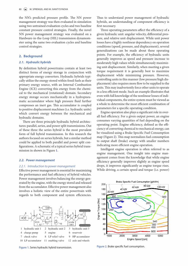
INTERNATIONAL JOURNAL OF FLUID POWER, 2017 VOL. 18, NO. 2, 79–91 https://doi.org/10.1080/14399776.2016.1232117 KEYWORDS Hydraulic hybrid; power management; neural network; dynamic programming ARTICLE HISTORY Received 23 June 2015 Accepted 16 August 2016 © 2016 Informa UK Limited, trading as Taylor & Francis Group CONTACT Michael Sprengel [email protected] Neural network based power management of hydraulic hybrid vehicles Michael Sprengel and Monika Ivantysynova Maha Fluid Power Research Center, Purdue University, West Lafayette, IN, USA ABSTRACT Effective power management is key to maximizing the performance and efficiency of hydraulic hybrid powertrains. However, the strong influence of future driving events on the optimal control policy limits the effectiveness of many approaches investigated to date. To address this issue the authors have proposed and investigated a novel power management controller that aims to predict online the accumulator’s near optimal state trajectory. It is demonstrated in this paper that if the optimal accumulator state trajectory is known, then an implementable control scheme can achieve near globally optimal fuel efficiency. Controller development began by optimally controlling a series hybrid over a representative drive cycle using Dynamic Programming (DP). A Neural Network (NN) was then trained to reproduce the DP optimal accumulator pressure trajectory based on the vehicle’s velocity over the previous thirty seconds. In this way the NN generalized the relationship between vehicle velocity and accumulator pressure. The NN power management controller’s performance was then evaluated on a hardware-in-the-loop transmission dynamometer using untrained drive cycles to demonstrate the generality of the proposed approach. During these untrained evaluation cycles the NN controller was able to decrease average fuel consumption by 25.8% when compared to a baseline constant pressure control strategy. 1. Introduction Vehicle hybridization through hydraulic hybrid trans- missions is a proven and effective means for significantly reducing fuel consumption in on-road vehicles. Over the years numerous academic institutions, governmental agencies, and companies have demonstrated the poten- tial of hydraulic hybrids. Recent examples include work performed by the United States Environmental Protection Agency where a series hybrid was demonstrated to reduce fuel consump- tion by 60–70% for a class 6 delivery vehicle when used in conjugation with a more efficient engine (Wendel et al. 2007). In 2012 the US Federal Transit Administration developed a modified series hybrid transmission for city busses in collaboration with industrial partners. ey measured a 29% increase in fuel economy over the most efficient electric hybrids, a 47% increase over an identical non-hybrid bus, and a 109% increase in fuel economy over conventional city busses. Equally impressive was the 36% lower estimated lifecycle cost for the hydraulic hybrid when compared against an electric hybrid bus (Heskitt et al. 2012). More recently PSA-Peugeot-Citroen unveiled their hydraulic hybrid power split transmission based passenger car. Marketed as a ‘Hybrid Air’ vehicle, the car obtained fuel economy improvements of 45% in city driving (PSA 2015). One aspect all of these transmissions have in com- mon is the need to balance the energy generated by the engine, with the energy stored and released from the hybrid transmission. Effectively controlling how this energy is balanced, as well as how all of the powertrain components are controlled, is essential to maximizing the fuel efficiency of hydraulic hybrid transmissions. In this paper the authors present a novel power man- agement strategy based on a Neural Network (NN) and Dynamic Programming (DP) with the goal of minimiz- ing fuel consumption. e authors began this research by developing a sim- ulation model for a reference series hydraulic hybrid vehicle. Next a 750 km long representative urban driving cycle was generated based on existing industry stand- ard cycles. e reference vehicle was then optimally controlled on this cycle using dynamic programming. DP provided both a target fuel consumption rate, and the optimal accumulator pressure profile. While DP is a powerful optimal control technique, its reliance on complete a priori cycle knowledge precludes its use as an implementable control scheme in most situations. us, a neural network was trained to predict the opti- mal DP pressure profile based on a short history of the vehicle’s past velocity. Next, a controller was developed to control the accumulator pressure in order to track
Transcript of Neural network based power management of hydraulic hybrid ...
InternatIonal Journal of fluId Power, 2017Vol. 18, no. 2, 79–91https://doi.org/10.1080/14399776.2016.1232117
KEYWORDSHydraulic hybrid; power management; neural network; dynamic programming
ARTICLE HISTORYreceived 23 June 2015 accepted 16 august 2016
© 2016 Informa uK limited, trading as taylor & francis Group
CONTACT Michael Sprengel [email protected]
Neural network based power management of hydraulic hybrid vehicles
Michael Sprengel and Monika Ivantysynova
Maha fluid Power research Center, Purdue university, west lafayette, In, uSa
ABSTRACTEffective power management is key to maximizing the performance and efficiency of hydraulic hybrid powertrains. However, the strong influence of future driving events on the optimal control policy limits the effectiveness of many approaches investigated to date. To address this issue the authors have proposed and investigated a novel power management controller that aims to predict online the accumulator’s near optimal state trajectory. It is demonstrated in this paper that if the optimal accumulator state trajectory is known, then an implementable control scheme can achieve near globally optimal fuel efficiency. Controller development began by optimally controlling a series hybrid over a representative drive cycle using Dynamic Programming (DP). A Neural Network (NN) was then trained to reproduce the DP optimal accumulator pressure trajectory based on the vehicle’s velocity over the previous thirty seconds. In this way the NN generalized the relationship between vehicle velocity and accumulator pressure. The NN power management controller’s performance was then evaluated on a hardware-in-the-loop transmission dynamometer using untrained drive cycles to demonstrate the generality of the proposed approach. During these untrained evaluation cycles the NN controller was able to decrease average fuel consumption by 25.8% when compared to a baseline constant pressure control strategy.
1. Introduction
Vehicle hybridization through hydraulic hybrid trans-missions is a proven and effective means for significantly reducing fuel consumption in on-road vehicles. Over the years numerous academic institutions, governmental agencies, and companies have demonstrated the poten-tial of hydraulic hybrids.
Recent examples include work performed by the United States Environmental Protection Agency where a series hybrid was demonstrated to reduce fuel consump-tion by 60–70% for a class 6 delivery vehicle when used in conjugation with a more efficient engine (Wendel et al. 2007). In 2012 the US Federal Transit Administration developed a modified series hybrid transmission for city busses in collaboration with industrial partners. They measured a 29% increase in fuel economy over the most efficient electric hybrids, a 47% increase over an identical non-hybrid bus, and a 109% increase in fuel economy over conventional city busses. Equally impressive was the 36% lower estimated lifecycle cost for the hydraulic hybrid when compared against an electric hybrid bus (Heskitt et al. 2012). More recently PSA-Peugeot-Citroen unveiled their hydraulic hybrid power split transmission based passenger car. Marketed as a ‘Hybrid Air’ vehicle, the car obtained fuel economy improvements of 45% in city driving (PSA 2015).
One aspect all of these transmissions have in com-mon is the need to balance the energy generated by the engine, with the energy stored and released from the hybrid transmission. Effectively controlling how this energy is balanced, as well as how all of the powertrain components are controlled, is essential to maximizing the fuel efficiency of hydraulic hybrid transmissions. In this paper the authors present a novel power man-agement strategy based on a Neural Network (NN) and Dynamic Programming (DP) with the goal of minimiz-ing fuel consumption.
The authors began this research by developing a sim-ulation model for a reference series hydraulic hybrid vehicle. Next a 750 km long representative urban driving cycle was generated based on existing industry stand-ard cycles. The reference vehicle was then optimally controlled on this cycle using dynamic programming. DP provided both a target fuel consumption rate, and the optimal accumulator pressure profile. While DP is a powerful optimal control technique, its reliance on complete a priori cycle knowledge precludes its use as an implementable control scheme in most situations. Thus, a neural network was trained to predict the opti-mal DP pressure profile based on a short history of the vehicle’s past velocity. Next, a controller was developed to control the accumulator pressure in order to track
80 M. SPrENgEl AND M. IvANTySyNovA
the NN’s predicted pressure profile. The NN power management strategy was then evaluated in simulation using two untrained evaluation cycles and two baseline constant pressure control strategies. Finally, the novel NN power management strategy was evaluated on a Hardware-in-the-Loop (HIL) transmission dynamom-eter using the same two evaluation cycles and baseline control strategies.
2. Background
2.1. Hydraulic hybrids
By definition hybrid powertrains contain at least two distinct forms of energy storage in conjunction with appropriate energy converters. Hydraulic hybrids typi-cally utilize the energy stored within fossil fuels as their primary energy source, with an Internal Combustion Engine (ICE) converting this energy from the chemi-cal to the mechanical (rotational) domain. Secondary energy storage occurs mechanically in a hydropneu-matic accumulator where high pressure fluid further compresses an inert gas. This accumulator is coupled to positive displacement machines (i.e. hydraulic units) which convert energy between the mechanical and hydraulic domains.
There are three principle hydraulic hybrid architec-tures: parallel, series, and power split transmissions. Out of these three the series hybrid is the most prevalent form of full hybrid transmission. In this research the authors focused on series hybrids, but a similar method could be applied to both parallel and power split con-figurations. A schematic of a typical series hybrid trans-mission in shown in Figure 1.
2.2. Power management
2.2.1. Introduction to power managementEffective power management is essential for maximizing the performance and fuel efficiency of hybrid vehicles. Power management involves balancing the energy gen-erated by the engine, with the energy stored and released from the accumulator. Effective power management also involves a holistic view of the entire powertrain with regards to both component and system efficiencies.
Thus to understand power management of hydraulic hybrids, an understanding of component efficiency is first necessary.
Three operating parameters affect the efficiency of a given hydraulic unit: angular velocity, differential pres-sure, and relative unit displacement. While unit power losses have a highly nonlinear dependency on operation conditions (speed, pressure, and displacement), several generalizations can be made about these operating points. For example, the efficiency of hydraulic units generally improves as speed and pressure increase to moderately high values while simultaneously maximiz-ing unit displacement. Similarly, when meeting a given torque requirement it is generally best to maximize displacement while minimizing pressure. However, controlling units in this manner (low pressure/high dis-placement) also requires more flow to be supplied to the units. This may inadvertently force other units to operate in a less efficient mode. Such an example illustrates that even with full knowledge of the nonlinear losses of indi-vidual components, the entire system must be viewed as a whole to determine the most efficient combination of parameters for a specific operating condition.
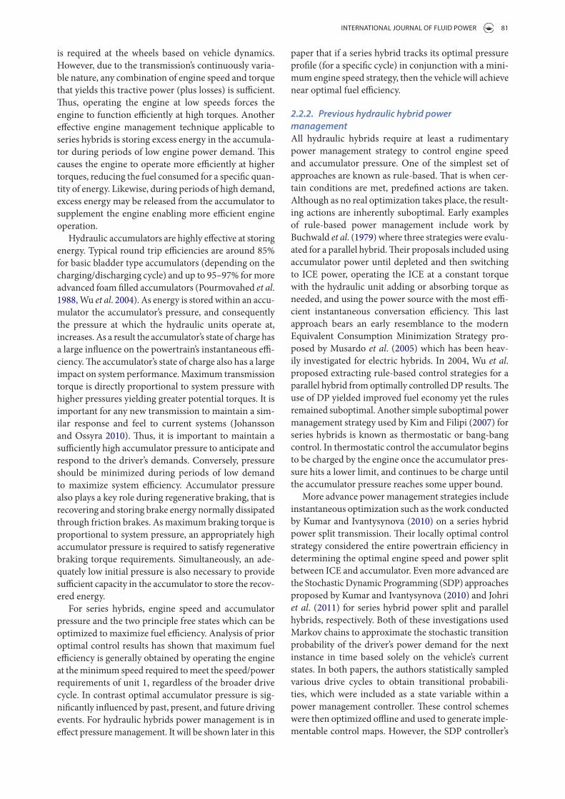
Engine operation also plays a significant role in over-all fuel efficiency. For a given output power, an engine consumes varying quantities of fuel depending on the operating point. Engine efficiency, defined as the effi-ciency of converting chemical to mechanical energy, can be visualized using a Brake Specific Fuel Consumption map (Figure 2). This map normalizes fuel consumption to output shaft (brake) energy with smaller numbers indicating more efficient engine operation.
Intelligent engine operation is often referred to as engine management. One insight into engine man-agement comes from the knowledge that while engine efficiency generally improves slightly as engine speed drops, it improves significantly as engine torque rises. While driving, a certain speed and torque (i.e. power)
1 hydraulic unit 1 2 hydraulic unit 2 3 hydraulic unit 3
4 charge pump 5 engine 6 reservoir
7 check valve 8 LP relief valve 9 HP accumulator
10 LP accumulator 11 enabling valve 12 axle and wheels
Figure 1. Series hydraulic hybrid transmission. Figure 2. Brake specific fuel consumption.
INTErNATIoNAl JourNAl of fluID PowEr 81
is required at the wheels based on vehicle dynamics. However, due to the transmission’s continuously varia-ble nature, any combination of engine speed and torque that yields this tractive power (plus losses) is sufficient. Thus, operating the engine at low speeds forces the engine to function efficiently at high torques. Another effective engine management technique applicable to series hybrids is storing excess energy in the accumula-tor during periods of low engine power demand. This causes the engine to operate more efficiently at higher torques, reducing the fuel consumed for a specific quan-tity of energy. Likewise, during periods of high demand, excess energy may be released from the accumulator to supplement the engine enabling more efficient engine operation.
Hydraulic accumulators are highly effective at storing energy. Typical round trip efficiencies are around 85% for basic bladder type accumulators (depending on the charging/discharging cycle) and up to 95–97% for more advanced foam filled accumulators (Pourmovahed et al. 1988, Wu et al. 2004). As energy is stored within an accu-mulator the accumulator’s pressure, and consequently the pressure at which the hydraulic units operate at, increases. As a result the accumulator’s state of charge has a large influence on the powertrain’s instantaneous effi-ciency. The accumulator’s state of charge also has a large impact on system performance. Maximum transmission torque is directly proportional to system pressure with higher pressures yielding greater potential torques. It is important for any new transmission to maintain a sim-ilar response and feel to current systems (Johansson and Ossyra 2010). Thus, it is important to maintain a sufficiently high accumulator pressure to anticipate and respond to the driver’s demands. Conversely, pressure should be minimized during periods of low demand to maximize system efficiency. Accumulator pressure also plays a key role during regenerative braking, that is recovering and storing brake energy normally dissipated through friction brakes. As maximum braking torque is proportional to system pressure, an appropriately high accumulator pressure is required to satisfy regenerative braking torque requirements. Simultaneously, an ade-quately low initial pressure is also necessary to provide sufficient capacity in the accumulator to store the recov-ered energy.
For series hybrids, engine speed and accumulator pressure and the two principle free states which can be optimized to maximize fuel efficiency. Analysis of prior optimal control results has shown that maximum fuel efficiency is generally obtained by operating the engine at the minimum speed required to meet the speed/power requirements of unit 1, regardless of the broader drive cycle. In contrast optimal accumulator pressure is sig-nificantly influenced by past, present, and future driving events. For hydraulic hybrids power management is in effect pressure management. It will be shown later in this
paper that if a series hybrid tracks its optimal pressure profile (for a specific cycle) in conjunction with a mini-mum engine speed strategy, then the vehicle will achieve near optimal fuel efficiency.
2.2.2. Previous hydraulic hybrid power managementAll hydraulic hybrids require at least a rudimentary power management strategy to control engine speed and accumulator pressure. One of the simplest set of approaches are known as rule-based. That is when cer-tain conditions are met, predefined actions are taken. Although as no real optimization takes place, the result-ing actions are inherently suboptimal. Early examples of rule-based power management include work by Buchwald et al. (1979) where three strategies were evalu-ated for a parallel hybrid. Their proposals included using accumulator power until depleted and then switching to ICE power, operating the ICE at a constant torque with the hydraulic unit adding or absorbing torque as needed, and using the power source with the most effi-cient instantaneous conversation efficiency. This last approach bears an early resemblance to the modern Equivalent Consumption Minimization Strategy pro-posed by Musardo et al. (2005) which has been heav-ily investigated for electric hybrids. In 2004, Wu et al. proposed extracting rule-based control strategies for a parallel hybrid from optimally controlled DP results. The use of DP yielded improved fuel economy yet the rules remained suboptimal. Another simple suboptimal power management strategy used by Kim and Filipi (2007) for series hybrids is known as thermostatic or bang-bang control. In thermostatic control the accumulator begins to be charged by the engine once the accumulator pres-sure hits a lower limit, and continues to be charge until the accumulator pressure reaches some upper bound.
More advance power management strategies include instantaneous optimization such as the work conducted by Kumar and Ivantysynova (2010) on a series hybrid power split transmission. Their locally optimal control strategy considered the entire powertrain efficiency in determining the optimal engine speed and power split between ICE and accumulator. Even more advanced are the Stochastic Dynamic Programming (SDP) approaches proposed by Kumar and Ivantysynova (2010) and Johri et al. (2011) for series hybrid power split and parallel hybrids, respectively. Both of these investigations used Markov chains to approximate the stochastic transition probability of the driver’s power demand for the next instance in time based solely on the vehicle’s current states. In both papers, the authors statistically sampled various drive cycles to obtain transitional probabili-ties, which were included as a state variable within a power management controller. These control schemes were then optimized offline and used to generate imple-mentable control maps. However, the SDP controller’s
82 M. SPrENgEl AND M. IvANTySyNovA
the simulation. The powertrain model was further vali-dated using measurements obtained from the hardware-in-the-loop test rig described in Section 6.2.
Engine dynamics are modeled as a force balance between brake torque, inertia, and load torque.
where ωCE is the engine’s speed, uCE is the normalized throttle, MWOT(ωCE) is the engine’s wide open throttle curve, ICE is the engine’s inertia, and M1 eff is unit 1’s effective torque.
The hydraulic units are modeled using governing equations and empirically derived loss models. Effective unit flow is given by:
where Qeff is the effective flow, V is the unit’s displace-ment, ω is the unit’s speed, β is the normalized unit dis-placement, and Qs is the empirically derived volumetric losses.
Effective torque is given by:
where Meff is the effective torque, V is the unit’s displace-ment, Δp is the unit’s differential pressure, β is the nor-malized unit displacement, and Ms is the empirically derived torque losses.
Accumulator pressure is modeled using the Beattie–Bridgeman Equation of State for nitrogen:
where p is the accumulator’s pressure (both fluid and gas), R is the universal gas constant, T is the gas’s tem-perature, υ is the gas’s molar density, and A, B, and C are constants.
Accumulator pressure is linked to the net oil flow into and out of the accumulator through Equations 6 and 7.
where Vgas is the gas volume and mmol is the gas’s molar mass.
(1)�CE = ∫uCEMWOT
(�CE
)−M1 eff
ICEdt
(2)Qeff =V��
2�± Qs
(3)Meff =VΔp�
2�±Ms
(4)p =RT
�2
(
1 −c
vT3
)
(� + B) −A
�2
(5)A = A0
(1 −
a
�
), B = B0
(
1 −b
�
)
R = 8.314 A0 = 136.2315 B0 = 0.05046
c = 4.2 × 10⁴ a = 0.02617 b = −0.00691
(6)� =Vgas
mmol
transition probabilities were calculated based on the same cycles for which the controller was evaluated, thus it is unknown how well this approach can be gen-eralized to unknown cycles. Many other power man-agement strategies have also been proposed, yet none of them can approach the global optimality of dynamic programming.
3. Reference application and system modeling
3.1. Reference vehicle
A compact passenger car serves as a reference vehicle for this investigation. Select parameters can be found in Table 1.
3.2. Transmission design and sizing
A series hybrid transmission with two units connected to the axle/wheels (Figure 1) was selected for this investiga-tion. The series hybrid is sized to meeting the same perfor-mance as the reference vehicle. Unit 1 is sized to fully load the engine at moderate pressure. Units 2 and 3 are sized to provide approximately the same maximum torque as the reference vehicle. The high pressure accumulator is sized to capture the maximum braking energy present within the drive cycles used in this work. Select parameters for the series hybrid transmission are located in Table 2.
3.3. System modeling
Developing a power management controller requires first modeling the series hybrid vehicle. All mode-ling was performed in MATLAB Simulink using gov-erning equations and accepted modeling techniques. Empirically derived engine performance and efficiency maps (Figure 2) were obtained from PSAT (Argonne National Laboratory 2015) while hydraulic unit volu-metric and torque efficiencies were measured in-house (Mikeska and Ivantysynova 2002). These empirical com-ponent models further enhance the powertrain model’s fidelity by incorporating real world measurements into
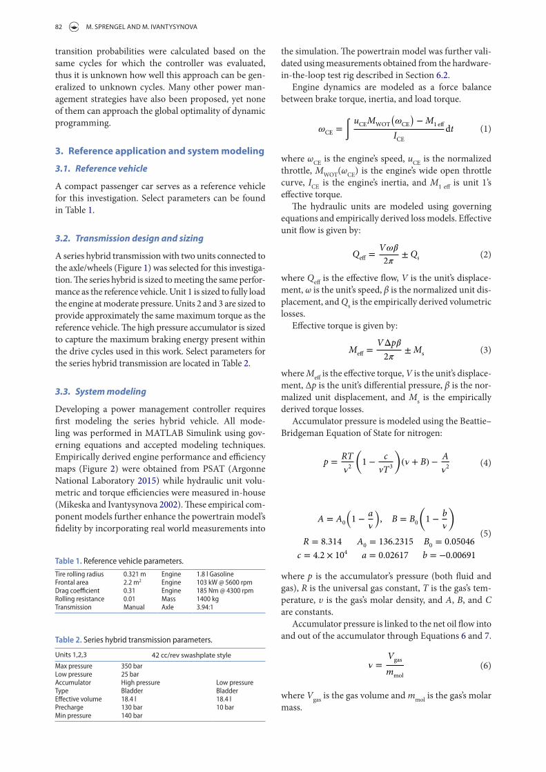
Table 1. reference vehicle parameters.
tire rolling radius 0.321 m engine 1.8 l Gasolinefrontal area 2.2 m2 engine 103 kw @ 5600 rpmdrag coefficient 0.31 engine 185 nm @ 4300 rpmrolling resistance 0.01 Mass 1400 kgtransmission Manual axle 3.94:1
Table 2. Series hybrid transmission parameters.
units 1,2,3 42 cc/rev swashplate styleMax pressure 350 barlow pressure 25 baraccumulator High pressure low pressuretype Bladder Bladdereffective volume 18.4 l 18.4 lPrecharge 130 bar 10 barMin pressure 140 bar
INTErNATIoNAl JourNAl of fluID PowEr 83
4.1. Drive cycle generation
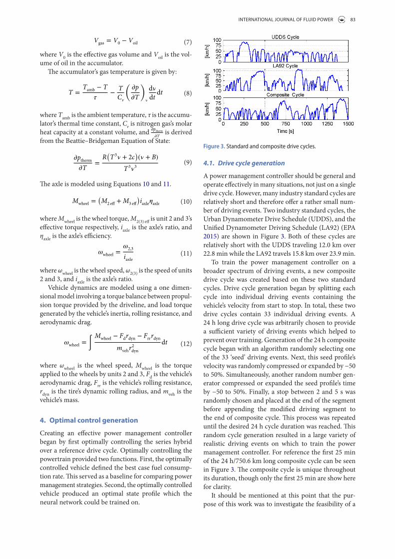
A power management controller should be general and operate effectively in many situations, not just on a single drive cycle. However, many industry standard cycles are relatively short and therefore offer a rather small num-ber of driving events. Two industry standard cycles, the Urban Dynamometer Drive Schedule (UDDS), and the Unified Dynamometer Driving Schedule (LA92) (EPA 2015) are shown in Figure 3. Both of these cycles are relatively short with the UDDS traveling 12.0 km over 22.8 min while the LA92 travels 15.8 km over 23.9 min.
To train the power management controller on a broader spectrum of driving events, a new composite drive cycle was created based on these two standard cycles. Drive cycle generation began by splitting each cycle into individual driving events containing the vehicle’s velocity from start to stop. In total, these two drive cycles contain 33 individual driving events. A 24 h long drive cycle was arbitrarily chosen to provide a sufficient variety of driving events which helped to prevent over training. Generation of the 24 h composite cycle began with an algorithm randomly selecting one of the 33 ‘seed’ driving events. Next, this seed profile’s velocity was randomly compressed or expanded by −50 to 50%. Simultaneously, another random number gen-erator compressed or expanded the seed profile’s time by −50 to 50%. Finally, a stop between 2 and 5 s was randomly chosen and placed at the end of the segment before appending the modified driving segment to the end of composite cycle. This process was repeated until the desired 24 h cycle duration was reached. This random cycle generation resulted in a large variety of realistic driving events on which to train the power management controller. For reference the first 25 min of the 24 h/750.6 km long composite cycle can be seen in Figure 3. The composite cycle is unique throughout its duration, though only the first 25 min are show here for clarity.
It should be mentioned at this point that the pur-pose of this work was to investigate the feasibility of a
where V0 is the effective gas volume and Voil is the vol-ume of oil in the accumulator.
The accumulator’s gas temperature is given by:
where Tamb is the ambient temperature, τ is the accumu-lator’s thermal time constant, Cv is nitrogen gas’s molar heat capacity at a constant volume, and �ptherm
�T is derived
from the Beattie–Bridgeman Equation of State:
The axle is modeled using Equations 10 and 11.
where Mwheel is the wheel torque, M2(3) eff is unit 2 and 3’s effective torque respectively, iaxle is the axle’s ratio, and ηaxle is the axle’s efficiency.
where ωwheel is the wheel speed, ω2(3) is the speed of units 2 and 3, and iaxle is the axle’s ratio.
Vehicle dynamics are modeled using a one dimen-sional model involving a torque balance between propul-sion torque provided by the driveline, and load torque generated by the vehicle’s inertia, rolling resistance, and aerodynamic drag.
where ωwheel is the wheel speed, Mwheel is the torque applied to the wheels by units 2 and 3, Fd is the vehicle’s aerodynamic drag, Frr is the vehicle’s rolling resistance, rdyn is the tire’s dynamic rolling radius, and mveh is the vehicle’s mass.
4. Optimal control generation
Creating an effective power management controller began by first optimally controlling the series hybrid over a reference drive cycle. Optimally controlling the powertrain provided two functions. First, the optimally controlled vehicle defined the best case fuel consump-tion rate. This served as a baseline for comparing power management strategies. Second, the optimally controlled vehicle produced an optimal state profile which the neural network could be trained on.
(7)Vgas = V0 − Voil
(8)T =Tamb − T
�−
T
Cv
(�p
�T
)
�
d�
dtdt
(9)�ptherm�T
=R(T3� + 2c
)(� + B)
T3�3
(10)Mwheel =(M2 eff +M3 eff
)iaxle�axle
(11)�wheel =�2,3
iaxle
(12)�wheel = ∫Mwheel − Fdrdyn − Frrrdyn
mvehr2dyn
dt
Figure 3. Standard and composite drive cycles.
84 M. SPrENgEl AND M. IvANTySyNovA
values. These cycle defined states and control came from the assumption that the drive cycle was perfectly fol-lowed. Thus, wheel speed and wheel torque were known for every point in time. It should also be noted that the purpose of this work was to evaluate a novel power management strategy, not to precisely predict the fuel consumption of a specific vehicle. It is the differences in fuel efficiency between various power management strategies, when evaluated in a given model, which are of the most interest. As such, the simplifications made are acceptable as they have been applied uniformly to each power management controller.
The series hybrid’s state space representation is given by:
where ωCE is the engine speed, ωwheel is the wheel speed, Vacm is the high pressure accumulator’s gas volume, Tacm is the high pressure accumulator’s gas temperature, pLP is the pressure in the low pressure system, uCE is the engine throttle command, β1, β2, and β3 are the normalized unit displacements for units 1, 2, and 3 respectively, and uenab is the enabling valve command.
The reduced state spaced representation used in the DP algorithm is given by:
where ωwheel has been removed as it is defined by the cycle, pLP has been removed as the low pressure system is assumed to maintain a fixed pressure, and desired engine speed ωCE des replaces engine throttle uCE. Using an internal speed controller for the engine throttle reduces computational expense by permitting a coarser control discretization while still ensuring accurate engine speed control. β2 and β3 were also removed as they were defined by the cycle (based on required torque and current system pressure). Finally the enabling valve command uenab was removed with the valve commanded to open any time a displacement other than zero was commanded for units 2 and 3.
High computational expense is one of DP’s primary disadvantages (Bertsekas and Bertsekas 1995), an issue mitigated through several techniques. First, the entire series hybrid vehicle model was placed in a repeating sub-system block within Simulink. This enabled the Simulink model to be opened once, and then ran simultaneously for hundreds of thousands of different simulations (as proposed in Liu and Peng 2006). Significant time savings were also achieved through system parallelization. DP is highly parallelizable with every optimization occurring
(14)X ≡ [
�CE �wheel Vacm Tacm pLP
]T
U ≡ [uCE �1 �2 �3 uenab
]T
(15)X ≡ [
�CE Vacm Tacm
]T
U ≡ [�CE des �1
]T
neural network based power management strategy, not to optimize the approach’s training and implementation. A further investigation might likely show that a shorter duration training segment would be equally effective, as would a broader variety of driving events.
4.2. Dynamic programming
Dynamic programming was used to optimally control the series hybrid over the composite cycle. DP is a pow-erful tool that guarantees a globally optimal solution is reached (down to the level of discretization) without the computational expense of full cycle enumeration. It is based on Bellman’s principle of optimality (Bellman 1956): ‘An optimal policy has the property that, whatever the initial state and optimal first decision may be, the remaining decisions constitute an optimal policy with regard to the state resulting from the first decision’.
Discrete time dynamic programming utilizes a state space modeling approach where key system states and controls are identified and discretized. The complete optimal control problem is then divided into a series of one stage sub problems containing only the current and subsequent time steps. Beginning at the final time step, the DP algorithm optimizes the controls for each state in the current stage before stepping backwards in time. This optimization occurs recursively until the initial time step is reached.
A key component of DP is the so called cost-to-finish matrix. This matrix contains the minimum cost to fin-ish the cycle for each state in the subsequent time step. By updating this matrix after each stage is optimized, essential information from all previous optimizations is condensed and stored into a single set of values. It is this matrix that enables the complete optimal control problem to be subdivided into one stage sub problems.
The DP algorithm was formulated using Equation 13.
where J∗ is the optimal cost, U is the control space, X is the state space, g is the transitional cost function, J∗k+1 is the optimal cost to finish, and k is the stage counter.
Because maximizing fuel efficiency was the primary goal of the power management controller, the DP cost function was configured to minimize fuel consumption. Due to space constraints a detailed explanation of the DP algorithm is not included herein, but can be found in Sprengel and Ivantysynova (2013).
A Simulink model of the series hybrid vehicle served as a plant for the DP algorithm. This Simulink model was configured in a modified state space representa-tion where key states and controls served as inputs and outputs. Simplifications were made to the model which generally involved either neglecting dynamics faster than the DP time step, or imposing certain cycle defined
(13)J∗k = minuk∈Uk
[g(Xk
||uk
)+ J∗k+1
(Xk+1
)]
INTErNATIoNAl JourNAl of fluID PowEr 85
as the reference pressure. Suboptimally controlled, the series hybrid still yielded a fuel consumption rate of 6.84 l/100 km, only 0.99% lower than the DP optimal value. These results provided motivation for this research by demonstrating that the more accurately the optimal pressure profile can be predicted, the closer a series hybrid can approach its globally optimal fuel efficiency.
5. Neural networks
5.1. Overview to neural networks
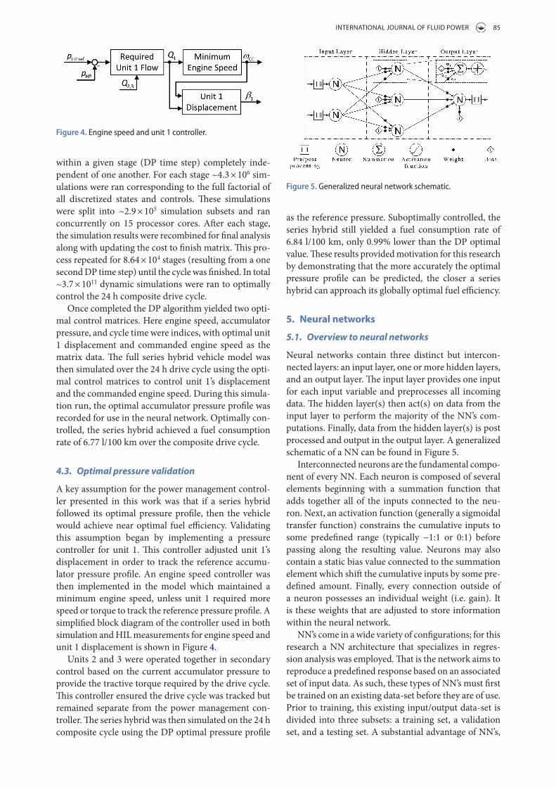
Neural networks contain three distinct but intercon-nected layers: an input layer, one or more hidden layers, and an output layer. The input layer provides one input for each input variable and preprocesses all incoming data. The hidden layer(s) then act(s) on data from the input layer to perform the majority of the NN’s com-putations. Finally, data from the hidden layer(s) is post processed and output in the output layer. A generalized schematic of a NN can be found in Figure 5.
Interconnected neurons are the fundamental compo-nent of every NN. Each neuron is composed of several elements beginning with a summation function that adds together all of the inputs connected to the neu-ron. Next, an activation function (generally a sigmoidal transfer function) constrains the cumulative inputs to some predefined range (typically −1:1 or 0:1) before passing along the resulting value. Neurons may also contain a static bias value connected to the summation element which shift the cumulative inputs by some pre-defined amount. Finally, every connection outside of a neuron possesses an individual weight (i.e. gain). It is these weights that are adjusted to store information within the neural network.
NN’s come in a wide variety of configurations; for this research a NN architecture that specializes in regres-sion analysis was employed. That is the network aims to reproduce a predefined response based on an associated set of input data. As such, these types of NN’s must first be trained on an existing data-set before they are of use. Prior to training, this existing input/output data-set is divided into three subsets: a training set, a validation set, and a testing set. A substantial advantage of NN’s,
within a given stage (DP time step) completely inde-pendent of one another. For each stage ~4.3 × 10⁶ sim-ulations were ran corresponding to the full factorial of all discretized states and controls. These simulations were split into ~2.9 × 10⁵ simulation subsets and ran concurrently on 15 processor cores. After each stage, the simulation results were recombined for final analysis along with updating the cost to finish matrix. This pro-cess repeated for 8.64 × 10⁴ stages (resulting from a one second DP time step) until the cycle was finished. In total ~3.7 × 10¹¹ dynamic simulations were ran to optimally control the 24 h composite drive cycle.
Once completed the DP algorithm yielded two opti-mal control matrices. Here engine speed, accumulator pressure, and cycle time were indices, with optimal unit 1 displacement and commanded engine speed as the matrix data. The full series hybrid vehicle model was then simulated over the 24 h drive cycle using the opti-mal control matrices to control unit 1’s displacement and the commanded engine speed. During this simula-tion run, the optimal accumulator pressure profile was recorded for use in the neural network. Optimally con-trolled, the series hybrid achieved a fuel consumption rate of 6.77 l/100 km over the composite drive cycle.
4.3. Optimal pressure validation
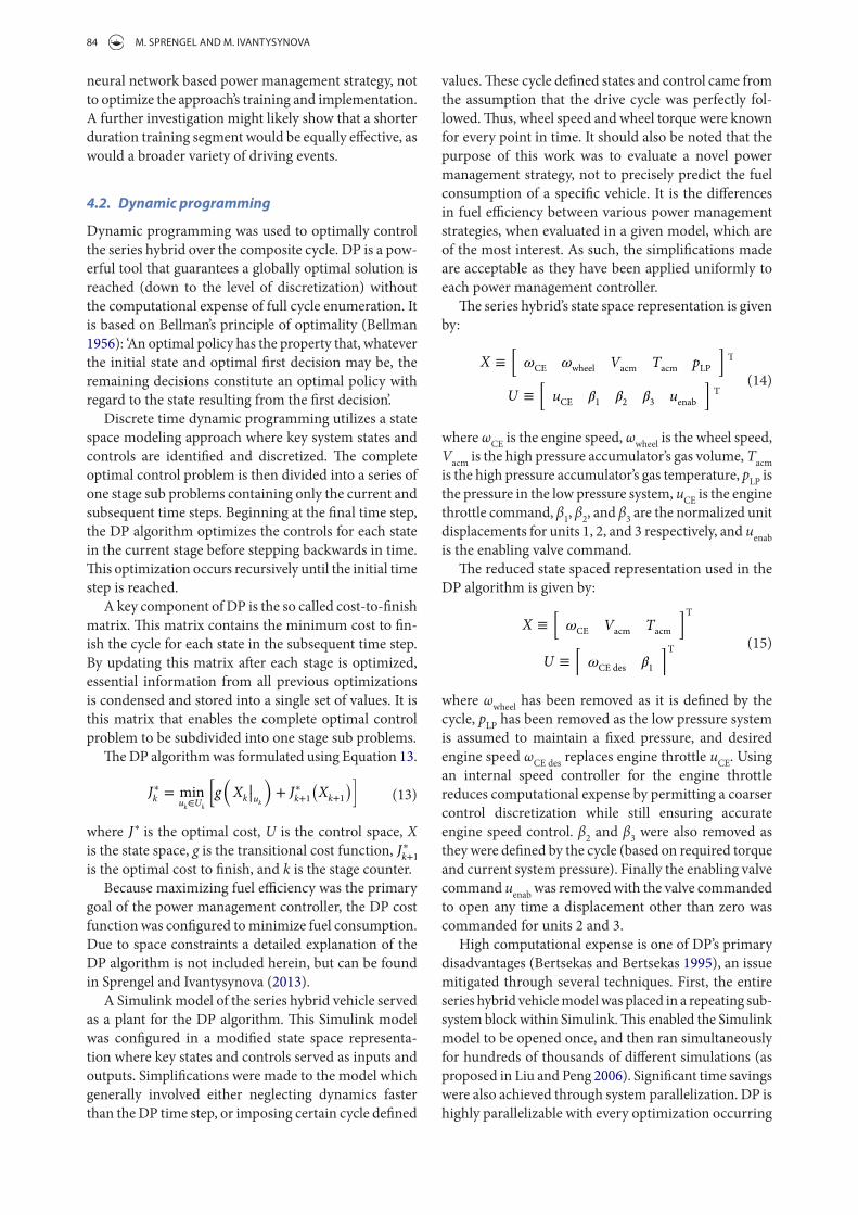
A key assumption for the power management control-ler presented in this work was that if a series hybrid followed its optimal pressure profile, then the vehicle would achieve near optimal fuel efficiency. Validating this assumption began by implementing a pressure controller for unit 1. This controller adjusted unit 1’s displacement in order to track the reference accumu-lator pressure profile. An engine speed controller was then implemented in the model which maintained a minimum engine speed, unless unit 1 required more speed or torque to track the reference pressure profile. A simplified block diagram of the controller used in both simulation and HIL measurements for engine speed and unit 1 displacement is shown in Figure 4.
Units 2 and 3 were operated together in secondary control based on the current accumulator pressure to provide the tractive torque required by the drive cycle. This controller ensured the drive cycle was tracked but remained separate from the power management con-troller. The series hybrid was then simulated on the 24 h composite cycle using the DP optimal pressure profile
Figure 4. engine speed and unit 1 controller.
Figure 5. Generalized neural network schematic.
86 M. SPrENgEl AND M. IvANTySyNovA
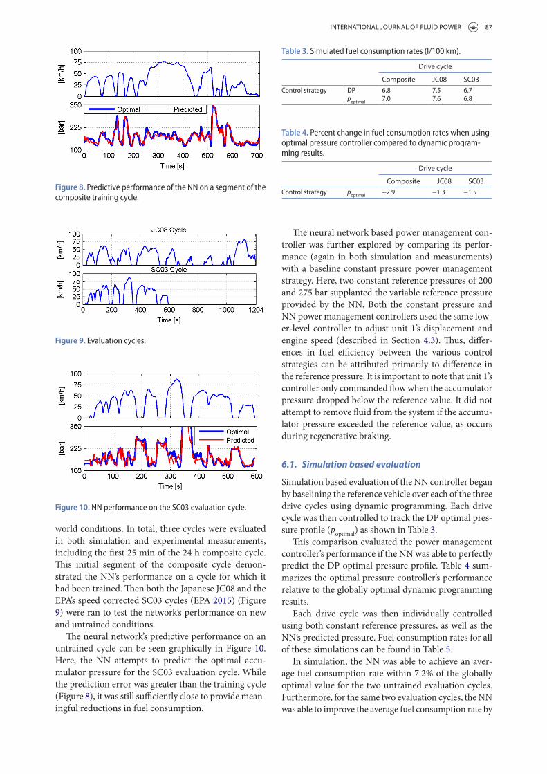
Bias values were included for every neuron in each of the layers. Finally, input and output variables were pre/post processed to normalize their maximum values to one. A schematic of this neural network can be found in Figure 7.
For this research the NN was constructed, trained, and implemented using MATLAB’s Neural Network Toolbox. This toolbox provided a powerful interface for developing NNs. The authors needed only to define the network’s architecture, the input/output data sets, and which training algorithm to use, and the toolbox trained the network. In the network’s final configura-tion the first 17 h of the 24 h DP optimal data-set was used as the training set. The two subsequent 3.5 h blocks were used as the validation and testing sets respectively. For training the Levenberg-Marquardt backpropagation algorithm (Moré 1978) was chosen due to its high per-formance and relatively low computational expense.
Once training concluded, the resulting NN was com-piled into a Simulink model by the toolbox. This model took in vehicle velocity and output the predicted optimal accumulator pressure. This Simulink model was then exported and used in both simulation and HIL eval-uation of the proposed power management strategy. An example of the NN’s ability to predict near optimal accumulator pressure for the composite training cycle can be seen in Figure 8.
6. Neural network performance assessment
Valuable insight was gained by assessing the NN’s per-formance on both drive cycles for which it had, and had not, been trained on. It is the NN’s performance on these untrained cycles which is of the most interest, as it pro-vides an indication of the network’s performance in real
and one that makes NN’s well suited for this research, is their ability to generalize trends in the data rather than simply memorizing input/output sets. A well structured and trained NN will have the ability to interpolate and extrapolate an output response based on new input sets that bear a resemblance to previously trained data sets.
Training begins by first defining the configuration of neurons, and then randomly initializing each weight’s value. In a process known as supervised learning, inputs for the training set are applied to the network with their response compared to the desired output values. This out-put response error is then back propagated through the network and used to update the NN’s weights. After the weights are updated, the validation data-set is run through the network. Training concludes once the maximum num-ber of training iterations is reached, the NN yields an acceptably low error in response to the training data, the error gradient between successive training iterations drops below a predefined value, the training set’s error begins to rise, or the validation set’s error begins to rise. This last condition helps to prevent memorization of the training set by ending the training once the NN begins to perform worse on generalizing trends. Finally, the testing data-set is run through the network as an additional check of the NN’s performance on data sets that it was not exposed to.
5.2. Neural networks for power management
Designing a neural network for power management began with determining the network’s inputs and out-puts. There exists no methodical approach for designing an optimal NN. Therefore both the selection of inputs and outputs, and the network’s configuration, were deter-mined through trial and error. It was found that a NN that predicted the optimal accumulator pressure profile based solely on a history of the vehicle’s velocity yielded satisfactory results. Many NNs use not only the instan-taneous value of an input variable, but also the temporal history of the input variable. For this research the last thirty seconds of vehicle velocity, discretized to one sec-ond intervals, served as inputs to the NN. It was found through experimentation that for this application a vehi-cle velocity history longer than thirty seconds did not markedly increase the network’s predictive performance.
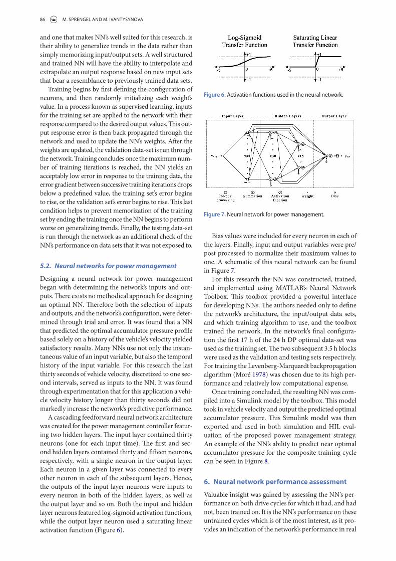
A cascading feedforward neural network architecture was created for the power management controller featur-ing two hidden layers. The input layer contained thirty neurons (one for each input time). The first and sec-ond hidden layers contained thirty and fifteen neurons, respectively, with a single neuron in the output layer. Each neuron in a given layer was connected to every other neuron in each of the subsequent layers. Hence, the outputs of the input layer neurons were inputs to every neuron in both of the hidden layers, as well as the output layer and so on. Both the input and hidden layer neurons featured log-sigmoid activation functions, while the output layer neuron used a saturating linear activation function (Figure 6).
Figure 6. activation functions used in the neural network.
Figure 7. neural network for power management.
INTErNATIoNAl JourNAl of fluID PowEr 87
The neural network based power management con-troller was further explored by comparing its perfor-mance (again in both simulation and measurements) with a baseline constant pressure power management strategy. Here, two constant reference pressures of 200 and 275 bar supplanted the variable reference pressure provided by the NN. Both the constant pressure and NN power management controllers used the same low-er-level controller to adjust unit 1’s displacement and engine speed (described in Section 4.3). Thus, differ-ences in fuel efficiency between the various control strategies can be attributed primarily to difference in the reference pressure. It is important to note that unit 1’s controller only commanded flow when the accumulator pressure dropped below the reference value. It did not attempt to remove fluid from the system if the accumu-lator pressure exceeded the reference value, as occurs during regenerative braking.
6.1. Simulation based evaluation
Simulation based evaluation of the NN controller began by baselining the reference vehicle over each of the three drive cycles using dynamic programming. Each drive cycle was then controlled to track the DP optimal pres-sure profile (poptimal) as shown in Table 3.
This comparison evaluated the power management controller’s performance if the NN was able to perfectly predict the DP optimal pressure profile. Table 4 sum-marizes the optimal pressure controller’s performance relative to the globally optimal dynamic programming results.
Each drive cycle was then individually controlled using both constant reference pressures, as well as the NN’s predicted pressure. Fuel consumption rates for all of these simulations can be found in Table 5.
In simulation, the NN was able to achieve an aver-age fuel consumption rate within 7.2% of the globally optimal value for the two untrained evaluation cycles. Furthermore, for the same two evaluation cycles, the NN was able to improve the average fuel consumption rate by
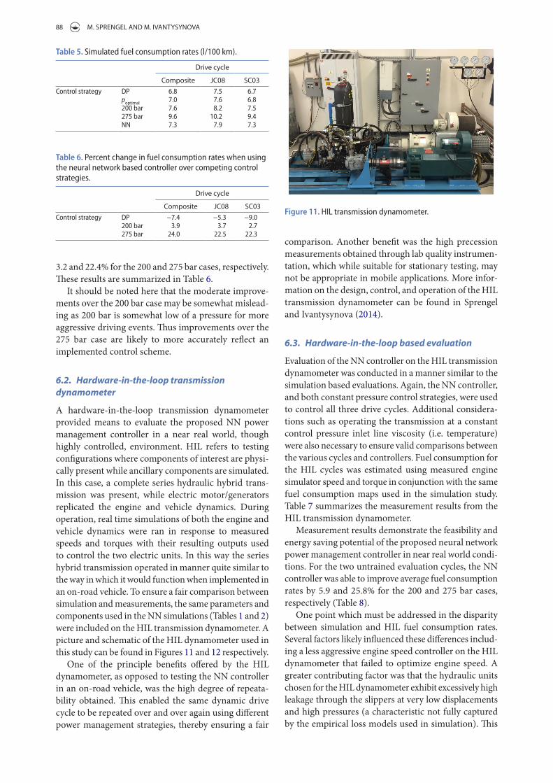
world conditions. In total, three cycles were evaluated in both simulation and experimental measurements, including the first 25 min of the 24 h composite cycle. This initial segment of the composite cycle demon-strated the NN’s performance on a cycle for which it had been trained. Then both the Japanese JC08 and the EPA’s speed corrected SC03 cycles (EPA 2015) (Figure 9) were ran to test the network’s performance on new and untrained conditions.
The neural network’s predictive performance on an untrained cycle can be seen graphically in Figure 10. Here, the NN attempts to predict the optimal accu-mulator pressure for the SC03 evaluation cycle. While the prediction error was greater than the training cycle (Figure 8), it was still sufficiently close to provide mean-ingful reductions in fuel consumption.
Figure 8. Predictive performance of the nn on a segment of the composite training cycle.
Figure 9. evaluation cycles.
Figure 10. nn performance on the SC03 evaluation cycle.
Table 3. Simulated fuel consumption rates (l/100 km).
Drive cycle
Composite JC08 SC03Control strategy dP 6.8 7.5 6.7
poptimal 7.0 7.6 6.8
Table 4. Percent change in fuel consumption rates when using optimal pressure controller compared to dynamic program-ming results.
Drive cycle
Composite JC08 SC03Control strategy poptimal −2.9 −1.3 −1.5
88 M. SPrENgEl AND M. IvANTySyNovA
comparison. Another benefit was the high precession measurements obtained through lab quality instrumen-tation, which while suitable for stationary testing, may not be appropriate in mobile applications. More infor-mation on the design, control, and operation of the HIL transmission dynamometer can be found in Sprengel and Ivantysynova (2014).
6.3. Hardware-in-the-loop based evaluation
Evaluation of the NN controller on the HIL transmission dynamometer was conducted in a manner similar to the simulation based evaluations. Again, the NN controller, and both constant pressure control strategies, were used to control all three drive cycles. Additional considera-tions such as operating the transmission at a constant control pressure inlet line viscosity (i.e. temperature) were also necessary to ensure valid comparisons between the various cycles and controllers. Fuel consumption for the HIL cycles was estimated using measured engine simulator speed and torque in conjunction with the same fuel consumption maps used in the simulation study. Table 7 summarizes the measurement results from the HIL transmission dynamometer.
Measurement results demonstrate the feasibility and energy saving potential of the proposed neural network power management controller in near real world condi-tions. For the two untrained evaluation cycles, the NN controller was able to improve average fuel consumption rates by 5.9 and 25.8% for the 200 and 275 bar cases, respectively (Table 8).
One point which must be addressed in the disparity between simulation and HIL fuel consumption rates. Several factors likely influenced these differences includ-ing a less aggressive engine speed controller on the HIL dynamometer that failed to optimize engine speed. A greater contributing factor was that the hydraulic units chosen for the HIL dynamometer exhibit excessively high leakage through the slippers at very low displacements and high pressures (a characteristic not fully captured by the empirical loss models used in simulation). This
3.2 and 22.4% for the 200 and 275 bar cases, respectively. These results are summarized in Table 6.
It should be noted here that the moderate improve-ments over the 200 bar case may be somewhat mislead-ing as 200 bar is somewhat low of a pressure for more aggressive driving events. Thus improvements over the 275 bar case are likely to more accurately reflect an implemented control scheme.
6.2. Hardware-in-the-loop transmission dynamometer
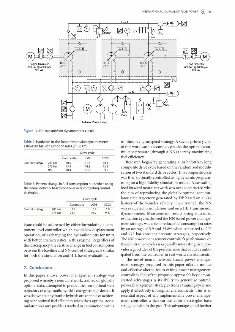
A hardware-in-the-loop transmission dynamometer provided means to evaluate the proposed NN power management controller in a near real world, though highly controlled, environment. HIL refers to testing configurations where components of interest are physi-cally present while ancillary components are simulated. In this case, a complete series hydraulic hybrid trans-mission was present, while electric motor/generators replicated the engine and vehicle dynamics. During operation, real time simulations of both the engine and vehicle dynamics were ran in response to measured speeds and torques with their resulting outputs used to control the two electric units. In this way the series hybrid transmission operated in manner quite similar to the way in which it would function when implemented in an on-road vehicle. To ensure a fair comparison between simulation and measurements, the same parameters and components used in the NN simulations (Tables 1 and 2) were included on the HIL transmission dynamometer. A picture and schematic of the HIL dynamometer used in this study can be found in Figures 11 and 12 respectively.
One of the principle benefits offered by the HIL dynamometer, as opposed to testing the NN controller in an on-road vehicle, was the high degree of repeata-bility obtained. This enabled the same dynamic drive cycle to be repeated over and over again using different power management strategies, thereby ensuring a fair
Table 5. Simulated fuel consumption rates (l/100 km).
Drive cycle
Composite JC08 SC03Control strategy dP 6.8 7.5 6.7
poptimal 7.0 7.6 6.8200 bar 7.6 8.2 7.5275 bar 9.6 10.2 9.4nn 7.3 7.9 7.3
Table 6. Percent change in fuel consumption rates when using the neural network based controller over competing control strategies.
Drive cycle
Composite JC08 SC03Control strategy dP −7.4 −5.3 −9.0
200 bar 3.9 3.7 2.7275 bar 24.0 22.5 22.3
Figure 11. HIl transmission dynamometer.
INTErNATIoNAl JourNAl of fluID PowEr 89
minimum engine speed strategy. A such a primary goal of this work was to accurately predict the optimal accu-mulator pressure (through a NN) thereby maximizing fuel efficiency.
Research began by generating a 24 h/750 km long composite drive cycle based on the randomized modifi-cation of two standard drive cycles. This composite cycle was then optimally controlled using dynamic program-ming on a high fidelity simulation model. A cascading feed forward neural network was next constructed with the aim of reproducing the globally optimal accumu-lator state trajectory generated by DP based on a 30 s history of the vehicle’s velocity. Once trained, the NN was evaluated in simulation, and on a HIL transmission dynamometer. Measurement results using untrained evaluation cycles showed the NN based power manage-ment strategy was able to reduce fuel consumption rates by an average of 5.9 and 25.8% when compared to 200 and 275 bar constant pressure strategies, respectively. The NN power management controller’s performance on these untrained cycles is especially interesting, as it pro-vides a good idea of the performance that could be antic-ipated from the controller in real world environments.
The novel neural network based power manage-ment strategy proposed in this paper offers a unique and effective alternative to exiting power management controllers. One of the proposed approach’s key demon-strated advantages is its ability to generalize optimal power management strategies from a training cycle and apply it effectively in original environments. This is an essential aspect of any implementable power manage-ment controller which various control strategies have struggled with in the past. This advantage could further
issue could be addressed by either formulating a com-ponent level controller which avoids low displacement operation, or exchanging the hydraulic units for units with better characteristics in this regime. Regardless of this discrepancy, the relative change in fuel consumption between the baseline and NN control strategies is similar for both the simulation and HIL based evaluations.
7. Conclusions
In this paper a novel power management strategy was proposed whereby a neural network, trained on globally optimal data, attempted to predict the near optimal state trajectory of a hydraulic hybrid’s energy storage device. It was shown that hydraulic hybrids are capable of achiev-ing near optimal fuel efficiency when their optimal accu-mulator pressure profile is tracked in conjunction with a
Figure 12. HIl transmission dynamometer circuit.
Table 7. Hardware-in-the-loop transmission dynamometer estimated fuel consumption rates (l/100 km).
Drive cycle
Composite JC08 SC03Control strategy 200 bar 10.6 11.7 10.1
275 bar 13.5 14.8 12.8nn 10.4 11.0 9.5
Table 8. Percent change in fuel consumption rates when using the neural network based controller over competing control strategies.
Drive cycle
Composite JC08 SC03Control strategy 200 bar 1.9 5.9 5.9
275 bar 23.0 25.7 25.8
90 M. SPrENgEl AND M. IvANTySyNovA
ReferencesArgonne National Laboratory, 2015. PSAT (powertrain
systems analysis toolkit). Available from: www.transportation.anl.gov.
Bellman, R., 1956. Dynamic programming and lagrange multipliers. Proceedings of the national academy of sciences of the United States of America, 42 (10), 767–769.
Bertsekas, D. and Bertsekas, D., 1995. Dynamic programming and optimal control. vol 1. Belmont, MA: Athena Scientific.
Buchwald, P., et al., 1979. Improvement of a citybus fuel economy using a hydraulic hybrid propulsion system – a theoretical and experimental study. Proceedings of the 1979 automotive engineering congress and exposition, 26 February–2 March 1979, Detroit, MI, USA. SAE paper 790305.
Environmental Protection Agency (EPA), 2015. Available from: http://www3.epa.gov/nvfel/testing/dynamometer.htm.
Heskitt, M., Smith, T., and Hopkins, J., 2012. Design & development of the LCO-140H series hydraulic hybrid low floor transit bus: BUSolutions final technical report (No. FTA Report No. 0018). US Federal Transportation Authority Report. Available from: http://ntl.bts.gov/lib/55000/55500/55504/FTA_Report_No._0018.pdf
Johansson, A. and Ossyra, J.-C., 2010. Hydraulic hybrid transmission design considerations for optimal customer satisfaction. Proceedings of the 7th international fluid power conference, 22–24 March 2010 Aachen, Germany.
Johri, R., Baseley, S., and Filipi, Z., 2011. Simultaneous optimization of supervisory control and gear shift logic for a parallel hydraulic hybrid refuse truck using stochastic dynamic programming. ASME/bath symposium on fluid power and motion control, Arlington, VI, USA.
Kim, Y. and Filipi, Z., 2007. Series hydraulic hybrid propulsion for a light truck-optimizing the thermostatic power management. In: Proceedings of the 8th International Conference on Engines for Automobile, 16–20 September 2007 Capri, Italy. SAE technical paper 2007-24-0080.
Kumar, R. and Ivantysynova, M., 2010. Investigation of various power management strategies for a class of hydraulic hybrid powertrains: theory and experiments. Proceedings of the 6th FPNI PhD symposium, 15–19 June 2010 West Lafayette, IN, USA.
Liu, J. and Peng, H., 2006. Control optimization for a power-split hybrid vehicle. American control conference, 14–16 June 2006 Minneapolis, MN, USA. IEEE.
Mikeska, D. and Ivantysynova, M., 2002. A precise steady-state model of displacement machines for the application in virtual prototyping of power-split drives. Proceedings of the 2nd FPNI PhD symposium, 3–6 July 2002 Modena, Italy.
Moré, J., 1978. The Levenberg-Marquardt algorithm: implementation and theory. In: Numerical analysis. Berlin Heidelberg: Springer, 105–116.
Musardo, C., et al., 2005. A-ECMS: an adaptive algorithm for hybrid electric vehicle energy management. European journal of control, 11 (4), 509–524.
Pourmovahed, A., et al., 1988. Experimental evaluation of hydraulic accumulator efficiency with and without elastomeric foam. Journal of propulsion and power, 4 (2), 185–192.
PSA-Peugeot-Citroen, 2015. Hybrid air, an innovative full hybrid gasoline system. Available from: http://www.psa-peugeot-citroen.com.
Sprengel, M. and Ivantysynova, M. 2013. Investigation and energetic analysis of a novel hydraulic hybrid architecture
be improved with online training of the NN. A control strategy can be envisioned where recently passed driving events are optimized off-line (though still in the trans-mission’s controller) with these optimal controls being used to slowly retrain the NN. In this way the NN could adapt to changes in driving style and vehicle characteris-tics. Neural networks also have the advantage of provid-ing near optimal control while imposing a relatively low computational burden on the vehicle’s controller. This is in contrast to certain other approaches which suffer from comparatively high computational loads during use.
Disclosure statementNo potential conflict of interest was reported by the authors.
FundingThis work was supported in part by a fellowship granted by the Graduate Automotive Technology Education (GATE) program DOE [award number: DE-EE0005568].
Notes on contributors
Michael Sprengel was born on 13 May 1987 in Cape Girardeau, Missouri (USA). He received his BS in Mechanical Engineering at the Missouri University of Science and Technology in 2010, his MS in Mechanical Engineering from Purdue University in 2013, and his PhD in Engineering from Purdue University in 2015. Currently he, is
employed as an R&D engineer/analyst at Czero in Fort Collins, CO. His research interests include the design, simu-lation, control, and optimization of novel energy efficient hydraulic hybrid systems for on-road and off-highway applications.
Monika Ivantysynova was born on 11 December 1955 in Polenz (Germany). She received her MSc degree in Mechanical Engineering and her PhD degree in Fluid Power from the Slovak Technical University of Bratislava, Czechoslovakia. After 7 years in fluid power industry she returned to uni-versity. In April 1996 she received a
Professorship in fluid power & control at the University of Duisburg (Germany). From 1999 until August 2004 she was Professor of Mechatronic Systems at the Technical University of Hamburg-Harburg. Since August 2004 she is Professor at Purdue University, USA. Her main research areas are energy saving actuator technology and model based optimization of displacement machines as well as modelling, simulation and testing of fluid power systems. Besides the book ‘Hydrostatic Pumps and Motors’ published in German and English, she has published more than 80 papers in technical journals and at international conferences.
ORCiDMichael Sprengel http://orcid.org/0000-0002-8556-6999

INTErNATIoNAl JourNAl of fluID PowEr 91
Wendel, G., et al., 2007. Hydraulic hybrid vehicle system panel. Michigan clean fleet conference, 17 May 2007 Detroit, MI, USA.
Wu, B., et al., 2004. Optimal power management for a hydraulic hybrid delivery truck. Vehicle system dynamics, 42 (1–2), 23–40.
for on-road vehicles. Proceedings of the 13th scandinavian international conference on fluid power, 3–5 June 2013 Linkoping, Sweden.
Sprengel, M. and Ivantysynova, M., 2014. Hardware-in-the-loop testing of a novel blended hydraulic hybrid transmission. Proceedings of the 8th FPNI PhD symposium on fluid power, 11–13 June 2014 Lappeenranta, Finland.