
Neugart Product Catalog 2010
92
Power. Precision. Partnership precision gearboxes
-
Upload
quantumautomation -
Category
Documents
-
view
1.324 -
download
9
Transcript of Neugart Product Catalog 2010

Neugart USA, LP - PA Facility 3047 Industrial Blvd. Bethel Park, PA 15102-2537, USAPhone: 1-412-835-4154Fax: 1-412-835-4194
Neugart USA, LP - VA Facility 508 Central Drive, Suite 107Virginia Beach VA, 23454, USAPhone: 1-757-418-2530 Fax: 1-757-962-0369
email: [email protected]: www.neugartusa.com
Power. Precision. Partnership
precision gearboxes
11/2
009
· mod
ifi ca
tions
res
erve
d

Introduction
Impress with power and precision.Inspire with partnership.
Dear Sir or Madam, Power, precision and partnership – these values have guided our business philosophy and our work attitude for over 80 years. We are pleased to present you our re-designed and newly structured catalog, listing our product range and demonstrating our experience and performance.
Our off ered product range includes numerous innovative, technologically mature, and highly reliable geared solutions for your power transmission, automation, or precisely controlled motion applications.
The six standard planetary gear series Neugart off ers cover a wide range of applications; from highest precision and performance to highest economy. As a technology partner, we also provide customized solutions; specialized, custom designed gearboxes, or high precision gearing parts – tailored precisely to your specifi c needs.
Please contact us with any questions about the new catalog, our products, or services – we appreciate every opportunity to assist and meet your automation, precise motion and power transmission requirements.
Bernd NeugartManaging partner
Thomas HerrManaging partner

1
PLN
WPL
NPL
FNPL
EW
PLE
PLFE
Table of contents
76 Ordering code
77 Options
78 – 79 Gearhead sizing/selection
80 Max. transferable output torque
81 Thermal specifications for continuous duty operation (S1)
82 – 83 Custom made gearboxes
84 – 85 Custom made gearing
86 – 88 Contact
2 – 5 The company
PLN 6 – 17
In-line gearhead Highest precision planetary
WPLN 18 – 29
Right angle gearhead Highest precision hypoid/planetary
PLFN 30 – 37
In-line rotating flange gearhead Highest precision, stiffness, and compact planetary
PLE 38 – 53
Low backlash planetary gearhead High value precision planetary
WPLE 54 – 67
Low backlash right angle gearhead High value precision bevel/planetary
PLFE 68 – 75
Low backlash rotating flange gearhead High value, stiffness, and compact planetary
2
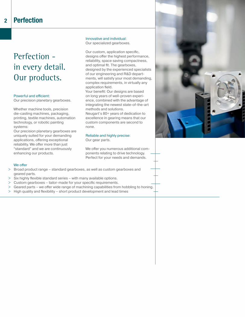
Perfection - in every detail.Our products.
Powerful and effi cient: Our precision planetary gearboxes. Whether machine tools, precision die-casting machines, packaging, printing, textile machines, automation technology, or robotic painting systems: Our precision planetary gearboxes are uniquely suited for your demanding applications, off ering exceptional reliability. We off er more than just “standard” and we are continuously enhancing our products.
We off er> Broad product range – standard gearboxes, as well as custom gearboxes and
geared parts.> Six highly fl exible standard series – with many available options. > Custom gearboxes – tailor-made for your specifi c requirements.> Geared parts – we off er wide range of machining capabilities from hobbling to honing. > High quality and fl exibility – short product development and lead times
Innovative and individual: Our specialized gearboxes.
Our custom, application specifi c, designs off er the highest performance, reliability, space saving compactness, and optimal fi t. The gearboxes, designed by the experienced specialists of our engineering and R&D depart-ments, will satisfy your most demanding, complex requirements, in virtually any application fi eld. Your benefi t: Our designs are based on long years of well-proven experi-ence, combined with the advantage of integrating the newest state-of-the-art methods and solutions.Neugart’s 80+ years of dedication to excellence in gearing means that our custom components are second to none. Reliable and highly precise: Our gear parts.
We off er you numerous additional com-ponents relating to drive technology. Perfect for your needs and demands.
Perfection

3Quality
Power - at a high level.Our quality.
Your satisfaction is our measuring stick, the quality of our products and services are always our top priority.
With our quality and environmental poli-cy, we secure and expand our economic success in all international markets.
We are:
> Goal oriented. Our concrete quality goals are the responsibility of the management and all employees.
> Committed. High emphasis is on developing and maintaining motivated, qualifi ed employees and optimized teams. In addition to ongoing education and training, our employees are given the authority and responsibility for their activities.
> Consistent. We have a process of continuous im-provements in place – and we combine the large steps of innovation by intro-ducing new technologies with the small steps of continuous optimization.
> Verifi able. We maintain and document a com-prehensive quality and environmental management system that comprises all phases of the manufacturing of goods and services. All processes relevant for design, manufacturing quality manage-ment are recorded in the documentation of or QM/EM system.

4 Service
Your added benefit. Our service.
We don‘t just make products; we create solutions – functional, economical and forward-looking. Therefore we provide, in close cooperation with our customers, a high level of application/product ori-ented service.
> From one source: From consulting to development. Your task, our job: we provide consulting and develop solutions for you and with you. More than 5% of our skilled em-ployees are working in product research, development, and design.
> At the most current level: Know-how and technology. You can trust in the most innovative solu-tions as well as proven manufacturing methods and know-how by our highly skilled employees. NCP, our essential software drive train design and optimiz-ing software, is available to you at no cost. Our website off ers comprehensive download of information, including CAD drawings, dimension sheets, manuals, and instructions.
> In all circumstances: Focus on effi ciency. You will benefi t from our exceptional value; best performance at fair prices and ongoing cost optimization. With our recently expanded production facility, we guarantee optimal delivery times for our standard products.

5Network
Global support.Our network.
Our exceptional product quality, support and service is appreciated worldwide: We are represented by subsidiaries or sales and service representatives in virtually every industrialized region of the world.
All key components of our products are exclusively manufactured in Germany. From assembly plants in the USA and China, we provide regional support to our customers, with a high level of fl exibility, off ering short delivery times and meeting local requirements.
6
PLN
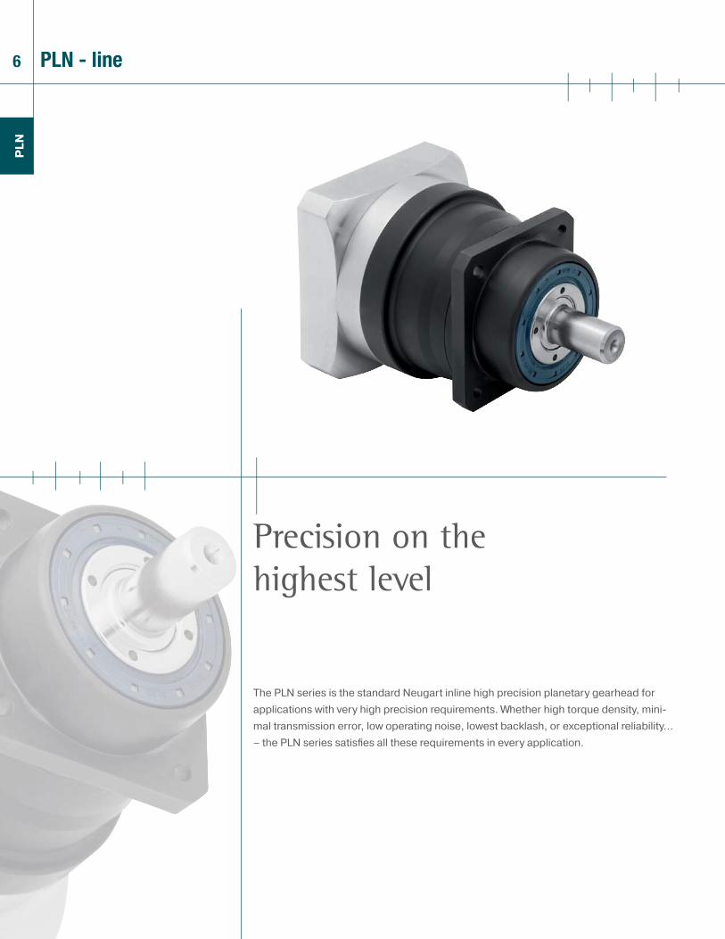
The PLN series is the standard Neugart inline high precision planetary gearhead for applications with very high precision requirements. Whether high torque density, mini-mal transmission error, low operating noise, lowest backlash, or exceptional reliability... – the PLN series satisfi es all these requirements in every application.
Precision on the highest level
PLN - line
7
PLN
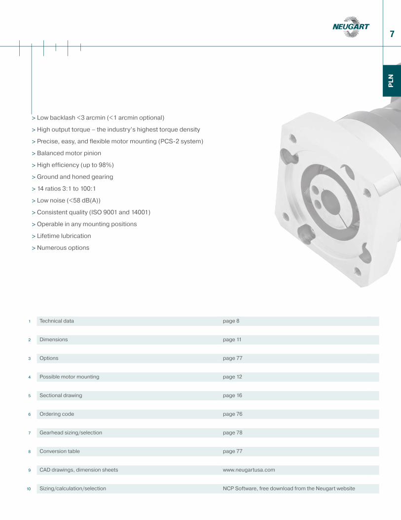
> Low backlash <3 arcmin (<1 arcmin optional)
> High output torque – the industry’s highest torque density
> Precise, easy, and flexible motor mounting (PCS-2 system)
> Balanced motor pinion
> High efficiency (up to 98%)
> Ground and honed gearing
> 14 ratios 3:1 to 100:1
> Low noise (<58 dB(A))
> Consistent quality (ISO 9001 and 14001)
> Operable in any mounting positions
> Lifetime lubrication
> Numerous options
1 Technical data page 8
2 Dimensions page 11
3 Options page 77
4 Possible motor mounting page 12
5 Sectional drawing page 16
6 Ordering code page 76
7 Gearhead sizing/selection page 78
8 Conversion table page 77
9 CAD drawings, dimension sheets www.neugartusa.com
10 Sizing/calculation/selection NCP Software, free download from the Neugart website

8
PLN
Technical dataPLN - line
Type-Size PLN 70 PLN 90 PLN 115 PLN 142 PLN 190 i (1) Z (2)
Nominal (rated continous duty) Output torque T2N
(3)(5)Nm
(lbin)
45 (398) 100 (885) 230 (2036) 450 (3983) 1000 (8850) 3
160 (531) 140 (1239) 300 (2655) 600 (5310) 1300 (11505) 465 (575) 140 (1239) 260 (2301) 750 (6638) 1600 (14160) 540 (354) 80 (708) 150 (1328) 450 (3983) 1000 (8850) 827 (239) 60 (531) 125 (1106) 305 (2699) 630 (5576) 1068 (602) 110 (974) 250 (2213) 780 (6903) 1500 (13275) 12
2
68 (602) 110 (974) 250 (2213) 780 (6903) 1500 (13275) 1577 (681) 150 (1328) 300 (2655) 1000 (8850) 1800 (15930) 1677 (681) 150 (1328) 300 (2655) 1000 (8850) 1800 (15930) 2065 (575) 140 (1239) 260 (2301) 900 (7965) 1800 (15930) 2577 (681) 150 (1328) 300 (2655) 1000 (8850) 1800 (15930) 3265 (575) 140 (1239) 260 (2301) 900 (7965) 1800 (15930) 4040 (354) 80 (708) 150 (1328) 450 (3983) 1000 (8850) 6427 (239) 60 (531) 125 (1106) 305 (2699) 630 (5576) 100
Type-Size PLN 70 PLN 90 PLN 115 PLN 142 PLN 190 i (1) Z (2)
Output torque sustainable 30,000 output shaft rotations(3)(5)(8)
Nm (lbin)
72 (637) 160 (1416) 368 (3257) 720 (6372) 1600 (14160) 3
196 (850) 224 (1982) 480 (4248) 960 (8496) 2080 (18408) 4
104 (920) 224 (1982) 416 (3682) 1200 (10620) 2560 (22656) 564 (566) 128 (1133) 240 (2124) 720 (6372) 1600 (14160) 843 (381) 96 (850) 200 (1770) 488 (4319) 1008 (8921) 10
109 (965) 176 (1558) 400 (3540) 1248 (11045) 2400 (21240) 12
2
109 (965) 176 (1558) 400 (3540) 1248 (11045) 2400 (21240) 15123 (1089) 240 (2124) 480 (4248) 1600 (14160) 2880 (25488) 16123 (1089) 240 (2124) 480 (4248) 1600 (14160) 2880 (25488) 20104 (920) 224 (1982) 416 (3682) 1440 (12744) 2880 (25488) 25
123 (1089) 240 (2124) 480 (4248) 1600 (14160) 2880 (25488) 32104 (920) 224 (1982) 416 (3682) 1440 (12744) 2880 (25488) 4064 (566) 128 (1133) 240 (2124) 720 (6372) 1600 (14160) 6443 (381) 96 (850) 200 (1770) 488 (4319) 1008 (8921) 100
Gearbox type PLN Z (2)
Gearbox life at full load h
20,000Gearbox life at 88% nominal torque T2N x 0,88 30,000
Emergency stop torque(6) Nm (lbin) 2 - times T2N
Effi ciency at full load(7) %98 195 2
Min. operating temp.(4)
°C (°F)-25 (-13)
Max. operating temp.(4) +90 (194)Protection class IP 65Lubrication lifetime lubricationMounting position anyRecommended motor fl ange / shaft tolerance DIN 42955-R
(1) Ratio (i=n1 rpm high speed side/n2 rpm low speed side)(2) Number of gear stages(3) Values reference output shaft speed n2=100 rpm, S1= 100% duty cycle, KA=1 application factor and T=30°C, 86°F ambient temperature(4) Measured at the middle of the gearbox housing surface (5) Dependent on the motor shaft diameter (6) Permissible about 1000 times during the gearbox life(7) Ratio dependent; based on n2=100 rpm output shaft speed(8) Permissible for 30,000 output shaft revolutions; see page 80
9
PLN
Technical dataPLN - line
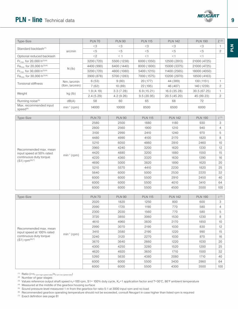
Type-Size PLN 70 PLN 90 PLN 115 PLN 142 PLN 190 Z (2)
Standard backlash(7)
arcmin<3 <3 <3 <3 <3 1<5 <5 <5 <5 <5 2
Optional reduced backlash <2 < 1 <1 <1 <1Frmax. for 20,000 h(3)(4)
N (lb)
3200 (720) 5500 (1238) 6000 (1350) 12500 (2813) 21000 (4725)Famax. for 20,000 h(3)(4) 4400 (990) 6400 (1440) 8000 (1800) 15000 (3375) 21000 (4725)Frmax. for 30,000 h(3)(4) 3200 (720) 4800 (1080) 5400 (1215) 11400 (2565) 18000 (4050)Famax. for 30,000 h(3)(4) 3900 (878) 5700 (1283) 7000 (1575) 13200 (2970) 18500 (4163)
Torsional stiff ness Nm /arcmin (lbin /arcmin)
6 (53) 9 (80) 20 (177) 44 (389) 130 (1151) 17 (62) 10 (89) 22 (195) 46 (407) 140 (1239) 2
Weight kg (lb)1.9 (4.19) 3.3 (7.28) 6.9 (15.21) 16.0 (35.28) 30.5 (67.25) 12.4 (5.29) 4.2 (9.26) 9.5 (20.95) 20.5 (45.20) 45 (99.23) 2
Running noise(5) dB(A) 58 60 65 68 72Max. recommended input speed(6) min-1 (rpm) 14000 10000 8500 6500 6000
Type-Size PLN 70 PLN 90 PLN 115 PLN 142 PLN 190 i (1)
Recommended max. mean input speed at 50% rated continuous duty torque (S1) rpm(6)(7)
min-1 (rpm)
2580 2500 1880 1180 930 32800 2560 1900 1210 940 43100 2990 2410 1240 970 54480 4990 4100 2170 1820 85210 6050 4860 2810 2460 103960 4240 3200 1620 1330 124420 4880 3200 1880 1550 154220 4360 3320 1630 1390 164690 5000 3820 1890 1620 205210 5570 4410 2230 1820 255640 6000 5000 2530 2220 326000 6000 5500 2910 2450 406000 6000 5500 4010 3410 646000 6000 5500 4500 3500 100
Type-Size PLN 70 PLN 90 PLN 115 PLN 142 PLN 190 i (1)
Recommended max. mean input speed at 100% rated continuous duty torque (S1) rpm(6)(7)
min-1 (rpm)
2020 1820 1250 800 600 32090 1720 1190 770 580 42300 2030 1560 770 580 53720 3850 3060 1530 1230 84610 4960 3830 2170 1850 102990 3070 2190 1030 830 123410 3580 2190 1220 990 153240 3120 2270 1030 870 163670 3640 2660 1220 1030 204300 4250 3280 1520 1200 254620 4920 3650 1710 1500 325260 5630 4380 2080 1710 406000 6000 5500 3430 2860 646000 6000 5500 4300 3500 100
(1) Ratio (i=n1 rpm high speed side/n2 rpm low speed side)(2) Number of gear stages(3) Values reference output shaft speed n2=100 rpm, S1= 100% duty cycle, KA=1 application factor and T=30°C, 86°F ambient temperature(4) Measured at the middle of the gearbox housing surface (5) Sound pressure level measured 1 m from the gearbox for ratio 5:1 at 3000 input rpm and no load(6) Recommended gearbox operating temperature should not be exceeded, consult Neugart in case higher than listed rpm is required(7) Exact definition see page 81
10
PLN
Technical dataPLN - line
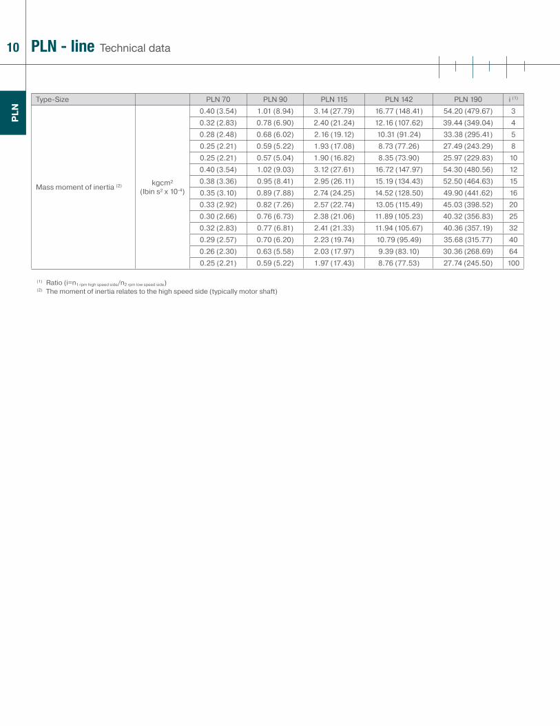
Type-Size PLN 70 PLN 90 PLN 115 PLN 142 PLN 190 i (1)
Mass moment of inertia (2) kgcm² (lbin s² x 10-4)
0.40 (3.54) 1.01 (8.94) 3.14 (27.79) 16.77 (148.41) 54.20 (479.67) 30.32 (2.83) 0.78 (6.90) 2.40 (21.24) 12.16 (107.62) 39.44 (349.04) 40.28 (2.48) 0.68 (6.02) 2.16 (19.12) 10.31 (91.24) 33.38 (295.41) 50.25 (2.21) 0.59 (5.22) 1.93 (17.08) 8.73 (77.26) 27.49 (243.29) 80.25 (2.21) 0.57 (5.04) 1.90 (16.82) 8.35 (73.90) 25.97 (229.83) 100.40 (3.54) 1.02 (9.03) 3.12 (27.61) 16.72 (147.97) 54.30 (480.56) 120.38 (3.36) 0.95 (8.41) 2.95 (26.11) 15.19 (134.43) 52.50 (464.63) 150.35 (3.10) 0.89 (7.88) 2.74 (24.25) 14.52 (128.50) 49.90 (441.62) 160.33 (2.92) 0.82 (7.26) 2.57 (22.74) 13.05 (115.49) 45.03 (398.52) 200.30 (2.66) 0.76 (6.73) 2.38 (21.06) 11.89 (105.23) 40.32 (356.83) 250.32 (2.83) 0.77 (6.81) 2.41 (21.33) 11.94 (105.67) 40.36 (357.19) 320.29 (2.57) 0.70 (6.20) 2.23 (19.74) 10.79 (95.49) 35.68 (315.77) 400.26 (2.30) 0.63 (5.58) 2.03 (17.97) 9.39 (83.10) 30.36 (268.69) 640.25 (2.21) 0.59 (5.22) 1.97 (17.43) 8.76 (77.53) 27.74 (245.50) 100
(1) Ratio (i=n1 rpm high speed side/n2 rpm low speed side)(2) The moment of inertia relates to the high speed side (typically motor shaft)
11
PLN
DimensionsPLN - line
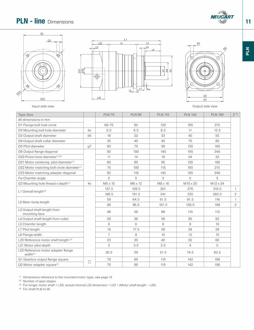
Type-Size PLN 70 PLN 90 PLN 115 PLN 142 PLN 190 Z (2)
All dimensions in mmD1 Flange bolt hole circle 68-75 85 120 165 215D2 Mounting bolt hole diameter 4x 5.5 6.5 8.5 11 13.5D3 Output shaft diameter k6 16 22 32 40 55D4 Output shaft collar diameter 35 40 45 70 80D5 Pilot diameter g7 60 70 90 130 160D6 Output fl ange diagonal 92 100 140 185 240D20 Pinion bore diameter(1)(4) 11 14 19 24 32D21 Motor centering pilot diameter(1) 60 80 95 130 180D22 Motor matching bolt circle diameter(1) 75 100 115 165 215D23 Motor matching adapter diagonal 92 116 145 185 240Fw Chamfer angle 5 5 5 5 5G3 Mounting hole thread x depth(1) 4x M5 x 10 M6 x 12 M8 x 16 M10 x 20 M12 x 24
L1 Overall length(3)137.5 159.5 201 276 310.5 1166.5 191.5 241 335 382.5 2
L2 Main-body length59 64.5 61.5 91.5 116 188 96.5 101.5 150.5 188 2
L3 Output shaft length from mounting face 48 56 88 110 112
L4 Output shaft length from collar 28 36 58 80 82L5 Chamfer length 8 6 8 8 10L7 Pilot length 19 17.5 28 28 28L8 Flange width 7 8 10 12 15L20 Reference motor shaft length (3) 23 30 40 50 60L21 Motor pilot depth 3 3.5 3.5 4 5L22 Reference motor adapter fl ange
width(3) 30.5 39 51.5 74.5 82.5
Q1 Gearbox output fl ange square 70 80 110 142 190Q3 Motor adapter square(1) 70 90 115 142 190
(1) Dimensions reference to the mounted motor-type, see page 12(2) Number of gear stages(3) For longer motor shaft > L20, actual minimal L22 dimension = L22 + (Motor shaft length – L20)(4) For shaft fit j6 to k6
Input side view Output side view
12
PLN
See pagefor other options 77
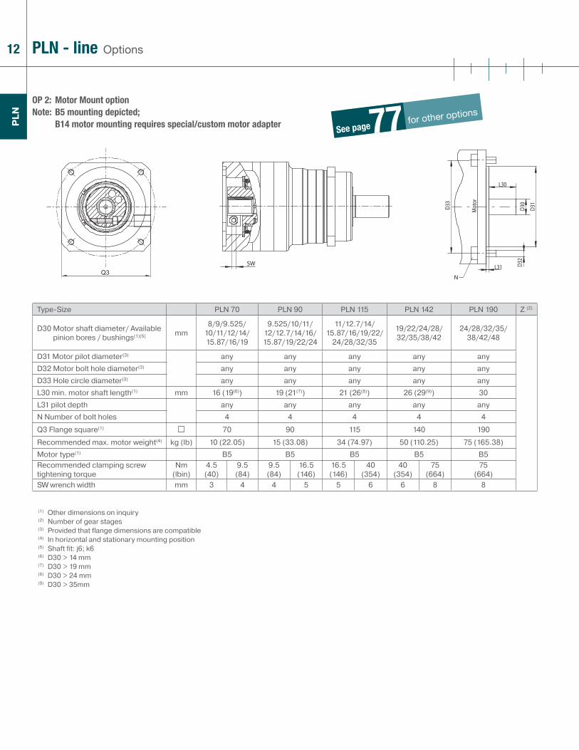
OP 2: Motor Mount option Note: B5 mounting depicted;
B14 motor mounting requires special/custom motor adapter
OptionsPLN - line
Type-Size PLN 70 PLN 90 PLN 115 PLN 142 PLN 190 Z (2)
D30 Motor shaft diameter/ Available pinion bores / bushings(1)(5) mm
8/9/9.525/10/11/12/14/15.87/16/19
9.525/10/11/12/12.7/14/16/15.87/19/22/24
11/12.7/14/15.87/16/19/22/
24/28/32/35
19/22/24/28/32/35/38/42
24/28/32/35/38/42/48
D31 Motor pilot diameter(3) any any any any anyD32 Motor bolt hole diameter(3) any any any any anyD33 Hole circle diameter(3) any any any any anyL30 min. motor shaft length(1) mm 16 (19(6)) 19 (21(7)) 21 (26(8)) 26 (29(9)) 30L31 pilot depth any any any any anyN Number of bolt holes 4 4 4 4 4
Q3 Flange square(1) 70 90 115 140 190
Recommended max. motor weight(4) kg (lb) 10 (22.05) 15 (33.08) 34 (74.97) 50 (110.25) 75 (165.38)Motor type(1) B5 B5 B5 B5 B5Recommended clamping screw tightening torque
Nm (lbin)
4.5(40)
9.5(84)
9.5(84)
16.5 (146)
16.5 (146)
40(354)
40(354)
75 (664)
75 (664)
SW wrench width mm 3 4 4 5 5 6 6 8 8
(1) Other dimensions on inquiry(2) Number of gear stages(3) Provided that flange dimensions are compatible(4) In horizontal and stationary mounting position(5) Shaft fit: j6; k6(6) D30 > 14 mm(7) D30 > 19 mm(8) D30 > 24 mm(9) D30 > 35mm

13
PLN
OP 5: Spline type code
OP 7: Output shaft with key DIN 6885 T1 (1)
OP 8: Special / custom shaft (3)(4)
OptionsPLN - line
Type-Size Spline type code Tooth face width Z Shaft end borePLN 70 DIN 5480 - W 16 x 0.8 x 30 x 18 x 7 m 15 DIN 332 DR M5x12.5PLN 70-OP14 DIN 5480 - W 19 x 0.8 x 30 x 22 x 7 m 15 DIN 332 DR M6x16PLN 90 DIN 5480 - W 22 x 0.8 x 30 x 26 x 7 m 21 DIN 332 DR M8x19PLN 115 DIN 5480 - W 32 x 1.25 x 30 x 24 x 7m 42 DIN 332 DR M12x28PLN 142 DIN 5480 - W 40 x 1.25 x 30 x 30 x 7m 65 DIN 332 DR M16x35PLN 190 DIN 5480 - W 55 x 2 x 30 x 26 x 7m 65 DIN 332 DR M20x42
Type-Size PLN 70 PLN 70-OP14 PLN 90 PLN 115 PLN 142 PLN 190Key type (Height x width x length) A5 x 5 x 25 A6 x 6 x 20 A6 x 6 x 28 A10 x 8 x 50 A12 x 8 x 65 A16 x 10 x 70D3 [k6] Output shaft diameter
mm
16 19 22 32 40 55L4 Output shaft length from collar 28 28 36 58 80 82L5 Key length 25 20 28 50 65 70L6 Distance from shaft end 2 4 4 4 8 6Z Shaft end bore M5 x 12.5 M6 x 16 M8 x 19 M12 x 28 M16 x 35 M20 x 42Output torque sustainable 30 000 output shaft rotations(2)
Nm (lbin) 77 (681) 77 (681) 150 (1328) 300 (2655) 1000 (8850) 1800 (15930)
Output shaft diameter D3Output shaft length from collar L4Output shaft length from mounting face L3Key length L5Distance from shaft end L6Key width BShaft end bore Z
(1) Sketch for variables see OP 8(2) Strength based on unidirectional dynamic load(3) Fax page with data or send sketch with your inquiry(4) On inquiry
14
PLN
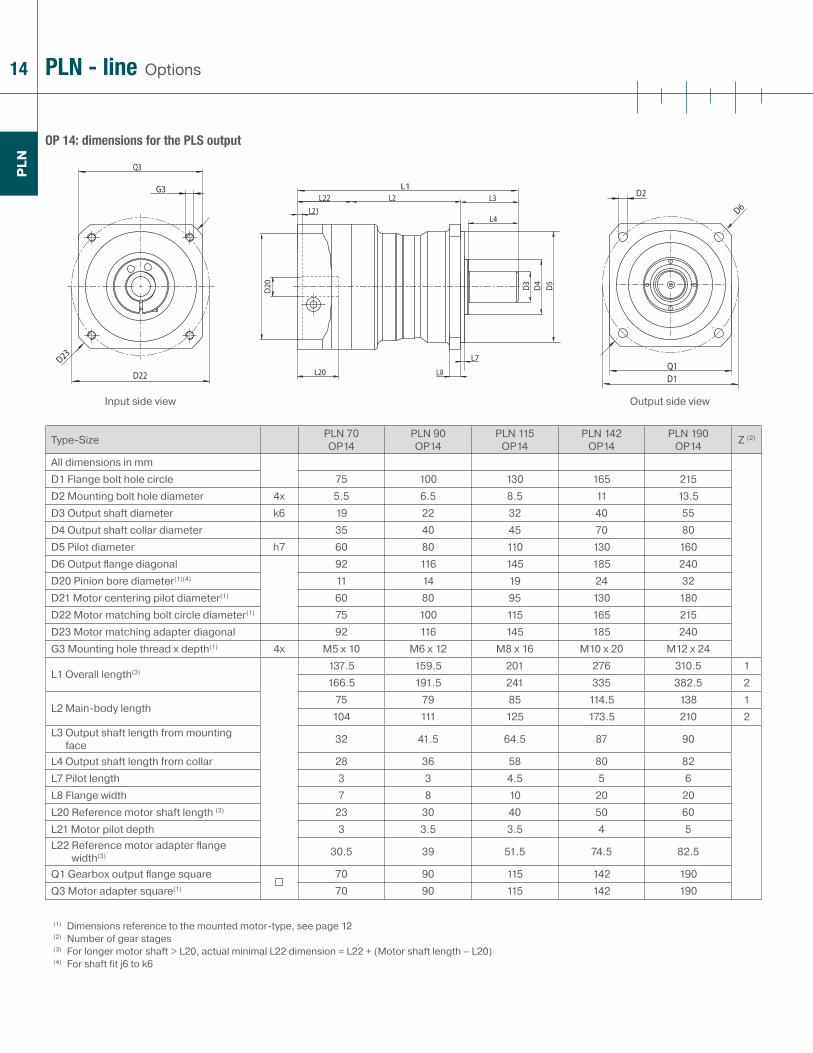
OP 14: dimensions for the PLS output
OptionsPLN - line
Type-Size PLN 70 OP14
PLN 90 OP14
PLN 115 OP14
PLN 142 OP14
PLN 190 OP14 Z (2)
All dimensions in mmD1 Flange bolt hole circle 75 100 130 165 215D2 Mounting bolt hole diameter 4x 5.5 6.5 8.5 11 13.5D3 Output shaft diameter k6 19 22 32 40 55D4 Output shaft collar diameter 35 40 45 70 80D5 Pilot diameter h7 60 80 110 130 160D6 Output fl ange diagonal 92 116 145 185 240D20 Pinion bore diameter(1)(4) 11 14 19 24 32D21 Motor centering pilot diameter(1) 60 80 95 130 180D22 Motor matching bolt circle diameter(1) 75 100 115 165 215D23 Motor matching adapter diagonal 92 116 145 185 240G3 Mounting hole thread x depth(1) 4x M5 x 10 M6 x 12 M8 x 16 M10 x 20 M12 x 24
L1 Overall length(3)137.5 159.5 201 276 310.5 1166.5 191.5 241 335 382.5 2
L2 Main-body length75 79 85 114.5 138 1
104 111 125 173.5 210 2L3 Output shaft length from mounting
face 32 41.5 64.5 87 90
L4 Output shaft length from collar 28 36 58 80 82L7 Pilot length 3 3 4.5 5 6L8 Flange width 7 8 10 20 20L20 Reference motor shaft length (3) 23 30 40 50 60L21 Motor pilot depth 3 3.5 3.5 4 5L22 Reference motor adapter fl ange
width(3) 30.5 39 51.5 74.5 82.5
Q1 Gearbox output fl ange square 70 90 115 142 190Q3 Motor adapter square(1) 70 90 115 142 190
(1) Dimensions reference to the mounted motor-type, see page 12(2) Number of gear stages(3) For longer motor shaft > L20, actual minimal L22 dimension = L22 + (Motor shaft length – L20)(4) For shaft fit j6 to k6
Input side view Output side view
15
PLN
OptionsPLN - line
Type-Size PLN 70 OP14
PLN 90 OP14
PLN 115 OP14
PLN 142 OP14
PLN 190 OP14 i (1)
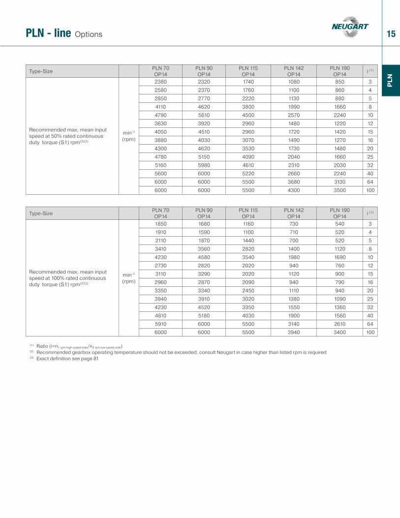
Recommended max. mean input speed at 50% rated continuous duty torque (S1) rpm(2)(3)
min-1 (rpm)
2380 2320 1740 1080 850 32580 2370 1760 1100 860 42850 2770 2220 1130 880 54110 4620 3800 1990 1660 84790 5610 4500 2570 2240 103630 3920 2960 1480 1220 124050 4510 2960 1720 1420 153880 4030 3070 1490 1270 164300 4620 3530 1730 1480 204780 5150 4090 2040 1660 255160 5980 4610 2310 2030 325600 6000 5220 2660 2240 406000 6000 5500 3680 3130 646000 6000 5500 4300 3500 100
Type-Size PLN 70 OP14
PLN 90 OP14
PLN 115 OP14
PLN 142 OP14
PLN 190 OP14 i (1)
Recommended max. mean input speed at 100% rated continuous duty torque (S1) rpm(2)(3)
min-1 (rpm)
1850 1680 1160 730 540 31910 1590 1100 710 520 42110 1870 1440 700 520 53410 3560 2820 1400 1120 84230 4580 3540 1980 1690 102730 2820 2020 940 760 123110 3290 2020 1120 900 152960 2870 2090 940 790 163350 3340 2450 1110 940 203940 3910 3020 1380 1090 254230 4520 3350 1550 1360 324810 5180 4030 1900 1560 405910 6000 5500 3140 2610 646000 6000 5500 3940 3400 100
(1) Ratio (i=n1 rpm high speed side/n2 rpm low speed side)(2) Recommended gearbox operating temperature should not be exceeded, consult Neugart in case higher than listed rpm is required(3) Exact definition see page 81
16
12
3
4
5
6
78
9
10
11
12
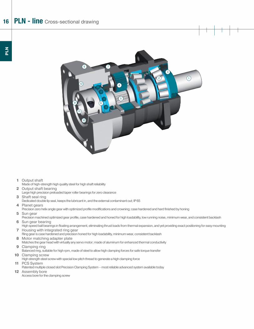
1 Output shaftMade of high-strength high quality steel for high shaft reliability
2 Output shaft bearingLarge high precision preloaded taper roller bearings for zero clearance
3 Shaft seal ringDedicated double lip seal, keeps the lubricant in, and the external contaminant out; IP 65
4 Planet gearsPrecision zero helix angle gear with optimized profi le modifi cations and crowning; case hardened and hard fi nished by honing
5 Sun gearPrecision machined optimized gear profi le, case hardened and honed for high loadability, low running noise, minimum wear, and consistent backlash
6 Sun gear bearingHigh speed ball bearings in fl oating arrangement, eliminating thrust loads from thermal expansion, and yet providing exact positioning for easy mounting
7 Housing with integrated ring gearRing gear is case hardened and precision honed for high loadability, minimum wear, consistent backlash
8 Motor matching adapter plateMatches the gear head with virtually any servo motor; made of aluminum for enhanced thermal conductivity
9 Clamping ringBalanced ring, suitable for high rpm, made of steel to allow high clamping forces for safe torque transfer
10 Clamping screwHigh strength steel screw with special low pitch thread to generate a high clamping force
11 PCS SystemPatented multiple closed slot Precision Clamping System – most reliable advanced system available today
12 Assembly boreAccess bore for the clamping screw
PLN - line Cross-sectional drawing
PLN

17for your notes
additional information www.neugartusa.com
PLN

18
WP
LN
The WPLN series gearhead is the enhanced right angle high precision planetary gearhead for applications with very high precision, requiring a right angle confi guration. The design of this unit features a hypoid right angle stage design (up to 10:1 ratio) and in higher ratios, an integration of the hypoid stage with high output torque planetary stage. As a result of the optimized, precision hardened and lapped hypoid gears, the noise generation is exceptionally low.
Compact, powerful, yet quiet
WPLN - line

19
WP
LN
> Low backlash <5 arcmin
> High output torque - the industry‘s highest torque density
> Small installation space
> Precise, easy, and flexible motor mounting (PCS-2 system)
> Balanced motor pinion
> High efficiency (up to 96%)
> Ground and honed gearing
> 11 ratios 4:1 to 100:1
> Low noise (<66 dB(A))
> Consistent quality (ISO 9001 and 14001)
> Operable in any mounting positions
> Lifetime lubrication
> Numerous options
> Balanced motor connection
1 Technical data page 20
2 Dimensions page 23
3 Options page 77
4 Possible motor mounting page 24
5 Sectional drawing page 28
6 Ordering code page 76
7 Gearhead sizing/selection page 78
8 Conversion table page 77
9 CAD drawings, dimension sheets www.neugartusa.com
10 Sizing/calculation/selection NCP Software, free download from the Neugart website
20
WP
LN
Technical dataWPLN - line
Type-Size WPLN 70 WPLN 90 WPLN 115 WPLN 142 i (1) Z (2)
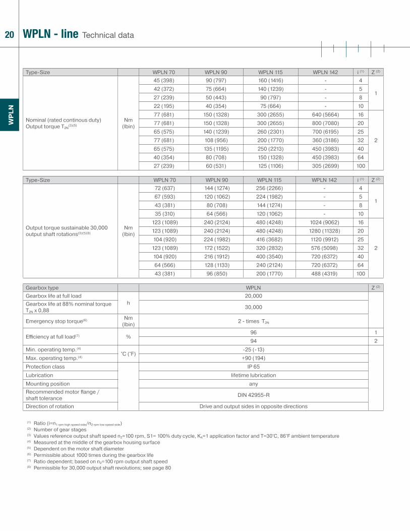
Nominal (rated continous duty) Output torque T2N
(3)(5)Nm
(lbin)
45 (398) 90 (797) 160 (1416) - 4
142 (372) 75 (664) 140 (1239) - 527 (239) 50 (443) 90 (797) - 822 (195) 40 (354) 75 (664) - 1077 (681) 150 (1328) 300 (2655) 640 (5664) 16
2
77 (681) 150 (1328) 300 (2655) 800 (7080) 2065 (575) 140 (1239) 260 (2301) 700 (6195) 2577 (681) 108 (956) 200 (1770) 360 (3186) 3265 (575) 135 (1195) 250 (2213) 450 (3983) 4040 (354) 80 (708) 150 (1328) 450 (3983) 6427 (239) 60 (531) 125 (1106) 305 (2699) 100
Type-Size WPLN 70 WPLN 90 WPLN 115 WPLN 142 i (1) Z (2)
Output torque sustainable 30,000 output shaft rotations(3)(5)(8)
Nm (lbin)
72 (637) 144 (1274) 256 (2266) - 4
167 (593) 120 (1062) 224 (1982) - 543 (381) 80 (708) 144 (1274) - 835 (310) 64 (566) 120 (1062) - 10
123 (1089) 240 (2124) 480 (4248) 1024 (9062) 16
2
123 (1089) 240 (2124) 480 (4248) 1280 (11328) 20104 (920) 224 (1982) 416 (3682) 1120 (9912) 25
123 (1089) 172 (1522) 320 (2832) 576 (5098) 32104 (920) 216 (1912) 400 (3540) 720 (6372) 4064 (566) 128 (1133) 240 (2124) 720 (6372) 6443 (381) 96 (850) 200 (1770) 488 (4319) 100
Gearbox type WPLN Z (2)
Gearbox life at full load h
20,000Gearbox life at 88% nominal torque T2N x 0,88 30,000
Emergency stop torque(6) Nm (lbin) 2 - times T2N
Effi ciency at full load(7) %96 194 2
Min. operating temp.(4)
°C (°F)-25 (-13)
Max. operating temp.(4) +90 (194)Protection class IP 65Lubrication lifetime lubricationMounting position anyRecommended motor fl ange / shaft tolerance DIN 42955-R
Direction of rotation Drive and output sides in opposite directions
(1) Ratio (i=n1 rpm high speed side/n2 rpm low speed side)(2) Number of gear stages(3) Values reference output shaft speed n2=100 rpm, S1= 100% duty cycle, KA=1 application factor and T=30°C, 86°F ambient temperature(4) Measured at the middle of the gearbox housing surface (5) Dependent on the motor shaft diameter (6) Permissible about 1000 times during the gearbox life(7) Ratio dependent; based on n2=100 rpm output shaft speed(8) Permissible for 30,000 output shaft revolutions; see page 80
21
WP
LN
Technical dataWPLN - line
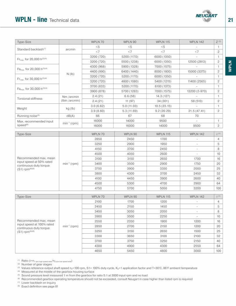
Type-Size WPLN 70 WPLN 90 WPLN 115 WPLN 142 Z (2)
Standard backlash(7) arcmin<5 <5 <5 - 1<7 <7 <7 <7 2
Frmax. for 20,000 h(3)(4)
N (lb)
3200 (720) 5200 (1170) 6000 (1350) - 13200 (720) 5500 (1238) 6000 (1350) 12500 (2813) 2
Famax. for 20,000 h(3)(4)4300 (968) 5900 (1328) 7000 (1575) - 14400 (990) 6400 (1440) 8000 (1800) 15000 (3375) 2
Frmax. for 30,000 h(3)(4)3200 (720) 5200 (1170) 6000 (1350) - 13200 (720) 4800 (1080) 5400 (1215) 11400 (2565) 2
Famax. for 30,000 h(3)(4)3700 (833) 5200 (1170) 6100 (1373) - 13900 (878) 5700 (1283) 7000 (1575) 13200 (2-970) 2
Torsional stiff ness Nm /arcmin (lbin /arcmin)
2.4 (21) 6.6 (58) 14.3 (127) - 12.4 (21) 11 (97) 34 (301) 58 (513) 2
Weight kg (lb)3.0 (6.62) 5.0 (11.03) 10.5 (23.15) - 13.9 (8.60) 5.3 (11.69) 9.2 (20.29) 21.5 (47.41) 2
Running noise(5) dB(A) 66 67 68 70
Max. recommended input speed(6) min-1 (rpm)
16000 14000 9500 - 116000 16000 14000 9500 2
Type-Size WPLN 70 WPLN 90 WPLN 115 WPLN 142 i (1)
Recommended max. mean input speed at 50% rated continuous duty torque (S1) rpm(6)(8)
min-1 (rpm)
2850 2450 1700 - 43250 2900 1950 - 54150 3700 2450 - 84500 4050 2600 - 103100 3150 2650 1700 163400 3500 2900 1750 203700 3900 3350 2000 253800 4300 3700 2450 324100 4450 3900 2600 404500 5300 4700 2900 644750 5700 5050 3200 100
Type-Size WPLN 70 WPLN 90 WPLN 115 WPLN 142 i (1)
Recommended max. mean input speed at 100% rated continuous duty torque (S1) rpm(6)(8)
min-1 (rpm)
2100 1700 1200 - 42450 2150 1450 - 53450 3050 2050 - 83900 3500 2250 - 102550 2350 1900 1200 162850 2700 2150 1200 203250 3150 2650 1500 253300 3650 3100 2100 323700 3750 3250 2150 404300 4900 4300 2550 644650 5450 4800 3000 100
(1) Ratio (i=n1 rpm high speed side/n2 rpm low speed side)(2) Number of gear stages(3) Values reference output shaft speed n2=100 rpm, S1= 100% duty cycle, KA=1 application factor and T=30°C, 86°F ambient temperature(4) Measured at the middle of the gearbox housing surface (5) Sound pressure level measured 1 m from the gearbox for ratio 5:1 at 3000 input rpm and no load(6) Recommended gearbox operating temperature should not be exceeded, consult Neugart in case higher than listed rpm is required(7) Lower backlash on inquiry(8) Exact definition see page 81
22
WP
LN
Technical dataWPLN - line
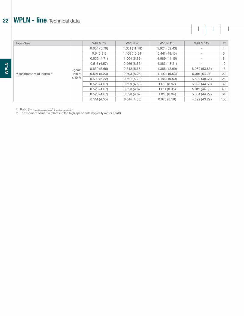
Type-Size WPLN 70 WPLN 90 WPLN 115 WPLN 142 i (1)
Mass moment of inertia (2)kgcm² (lbin s² x 10-4)
0.654 (5.79) 1.331 (11.78) 5.924 (52.43) - 40.6 (5.31) 1.168 (10.34) 5.441 (48.15) - 5
0.532 (4.71) 1.004 (8.89) 4.989 (44.15) - 80.516 (4.57) 0.966 (8.55) 4.883 (43.21) - 100.639 (5.66) 0.642 (5.68) 1.366 (12.09) 6.082 (53.83) 160.591 (5.23) 0.593 (5.25) 1.190 (10.53) 6.016 (53.24) 200.590 (5.22) 0.591 (5.23) 1.186 (10.50) 5.500 (48.68) 250.528 (4.67) 0.529 (4.68) 1.013 (8.97) 5.028 (44.50) 320.528 (4.67) 0.528 (4.67) 1.011 (8.95) 5.012 (44.36) 400.528 (4.67) 0.528 (4.67) 1.010 (8.94) 5.004 (44.29) 640.514 (4.55) 0.514 (4.55) 0.970 (8.58) 4.892 (43.29) 100
(1) Ratio (i=n1 rpm high speed side/n2 rpm low speed side)(2) The moment of inertia relates to the high speed side (typically motor shaft)
23
WP
LN
DimensionsWPLN - line
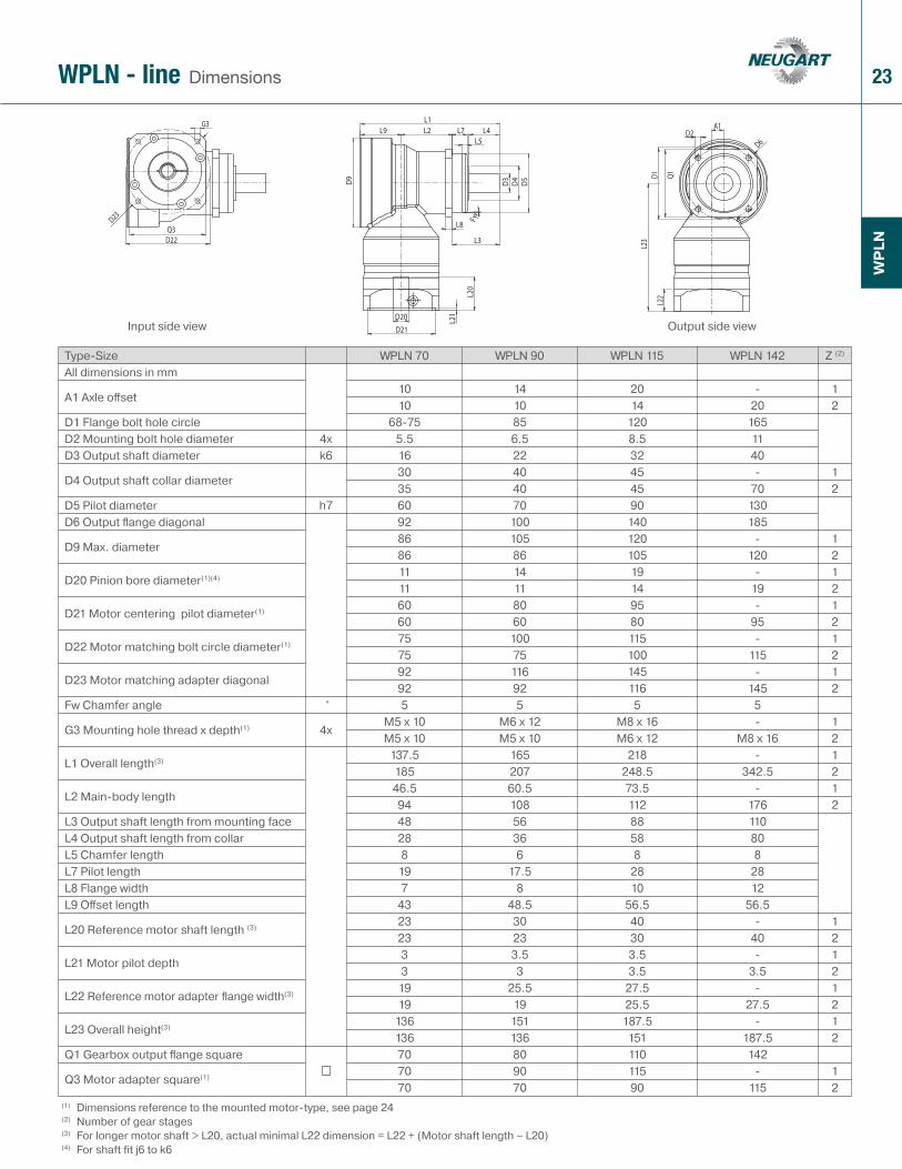
Type-Size WPLN 70 WPLN 90 WPLN 115 WPLN 142 Z (2)
All dimensions in mm
A1 Axle off set10 14 20 - 110 10 14 20 2
D1 Flange bolt hole circle 68-75 85 120 165D2 Mounting bolt hole diameter 4x 5.5 6.5 8.5 11D3 Output shaft diameter k6 16 22 32 40
D4 Output shaft collar diameter 30 40 45 - 135 40 45 70 2
D5 Pilot diameter h7 60 70 90 130D6 Output fl ange diagonal 92 100 140 185
D9 Max. diameter86 105 120 - 186 86 105 120 2
D20 Pinion bore diameter(1)(4) 11 14 19 - 111 11 14 19 2
D21 Motor centering pilot diameter(1) 60 80 95 - 160 60 80 95 2
D22 Motor matching bolt circle diameter(1) 75 100 115 - 175 75 100 115 2
D23 Motor matching adapter diagonal92 116 145 - 192 92 116 145 2
Fw Chamfer angle ° 5 5 5 5
G3 Mounting hole thread x depth(1) 4xM5 x 10 M6 x 12 M8 x 16 - 1M5 x 10 M5 x 10 M6 x 12 M8 x 16 2
L1 Overall length(3) 137.5 165 218 - 1185 207 248.5 342.5 2
L2 Main-body length46.5 60.5 73.5 - 194 108 112 176 2
L3 Output shaft length from mounting face 48 56 88 110L4 Output shaft length from collar 28 36 58 80L5 Chamfer length 8 6 8 8L7 Pilot length 19 17.5 28 28L8 Flange width 7 8 10 12L9 Off set length 43 48.5 56.5 56.5
L20 Reference motor shaft length (3) 23 30 40 - 123 23 30 40 2
L21 Motor pilot depth3 3.5 3.5 - 13 3 3.5 3.5 2
L22 Reference motor adapter fl ange width(3) 19 25.5 27.5 - 119 19 25.5 27.5 2
L23 Overall height(3) 136 151 187.5 - 1136 136 151 187.5 2
Q1 Gearbox output fl ange square 70 80 110 142
Q3 Motor adapter square(1) 70 90 115 - 170 70 90 115 2
(1) Dimensions reference to the mounted motor-type, see page 24(2) Number of gear stages(3) For longer motor shaft > L20, actual minimal L22 dimension = L22 + (Motor shaft length – L20)(4) For shaft fit j6 to k6
Input side view Output side view
24
WP
LN
SW
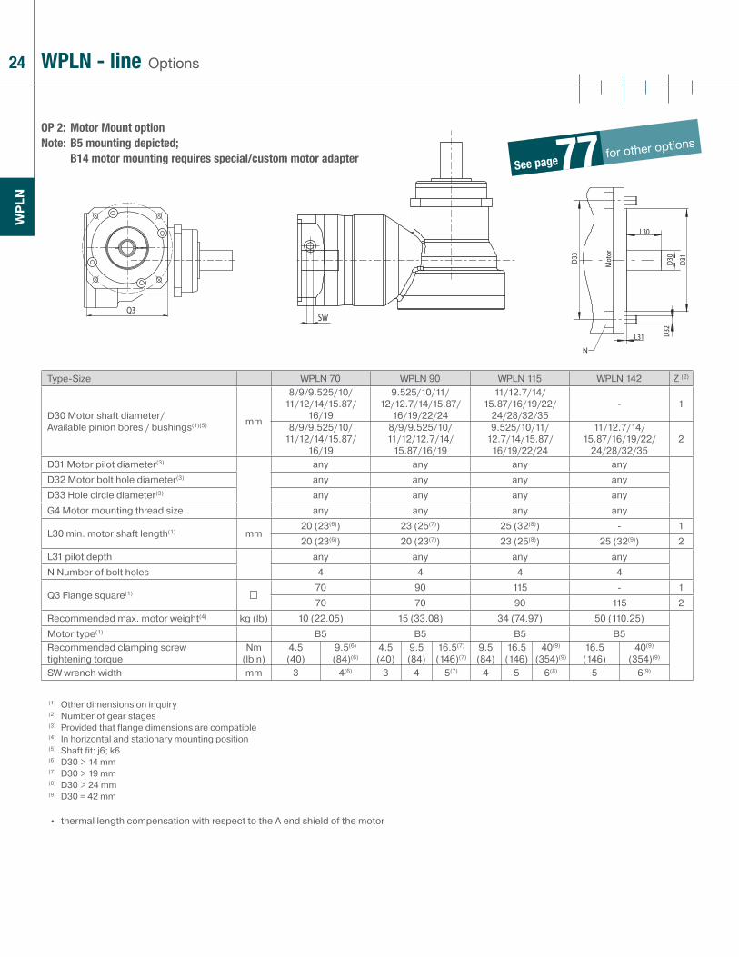
OP 2: Motor Mount option Note: B5 mounting depicted;
B14 motor mounting requires special/custom motor adapter
OptionsWPLN - line
Type-Size WPLN 70 WPLN 90 WPLN 115 WPLN 142 Z (2)
D30 Motor shaft diameter/ Available pinion bores / bushings(1)(5) mm
8/9/9.525/10/11/12/14/15.87/
16/19
9.525/10/11/12/12.7/14/15.87/
16/19/22/24
11/12.7/14/15.87/16/19/22/
24/28/32/35- 1
8/9/9.525/10/11/12/14/15.87/
16/19
8/9/9.525/10/11/12/12.7/14/
15.87/16/19
9.525/10/11/12.7/14/15.87/
16/19/22/24
11/12.7/14/15.87/16/19/22/
24/28/32/352
D31 Motor pilot diameter(3) any any any anyD32 Motor bolt hole diameter(3) any any any anyD33 Hole circle diameter(3) any any any anyG4 Motor mounting thread size any any any any
L30 min. motor shaft length(1) mm20 (23(6)) 23 (25(7)) 25 (32(8)) - 120 (23(6)) 20 (23(7)) 23 (25(8)) 25 (32(9)) 2
L31 pilot depth any any any anyN Number of bolt holes 4 4 4 4
Q3 Flange square(1)70 90 115 - 170 70 90 115 2
Recommended max. motor weight(4) kg (lb) 10 (22.05) 15 (33.08) 34 (74.97) 50 (110.25)Motor type(1) B5 B5 B5 B5Recommended clamping screw tightening torque
Nm (lbin)
4.5(40)
9.5(6)
(84)(6)4.5(40)
9.5(84)
16.5(7)
(146)(7)9.5(84)
16.5(146)
40(9)
(354)(9)16.5(146)
40(9)
(354)(9)
SW wrench width mm 3 4(6) 3 4 5(7) 4 5 6(8) 5 6(9)
(1) Other dimensions on inquiry(2) Number of gear stages(3) Provided that flange dimensions are compatible(4) In horizontal and stationary mounting position(5) Shaft fit: j6; k6(6) D30 > 14 mm(7) D30 > 19 mm(8) D30 > 24 mm(9) D30 = 42 mm
• thermal length compensation with respect to the A end shield of the motor
See pagefor other options 77
25
WP
LN
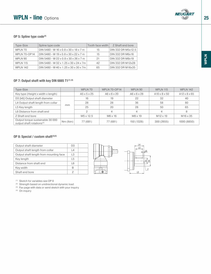
OP 5: Spline type code(4)
OP 7: Output shaft with key DIN 6885 T1(1) (4)
OP 8: Special / custom shaft(3)(4)
OptionsWPLN - line
Type-Size Spline type code Tooth face width Z Shaft end boreWPLN 70 DIN 5480 - W 16 x 0.8 x 30 x 18 x 7 m 15 DIN 332 DR M5x12.5WPLN 70-OP14 DIN 5480 - W 19 x 0.8 x 30 x 22 x 7 m 15 DIN 332 DR M6x16WPLN 90 DIN 5480 - W 22 x 0.8 x 30 x 26 x 7 m 21 DIN 332 DR M8x19WPLN 115 DIN 5480 - W 32 x 1.25 x 30 x 24 x 7m 42 DIN 332 DR M12x28WPLN 142 DIN 5480 - W 40 x 1.25 x 30 x 30 x 7m 65 DIN 332 DR M16x35
Type-Size WPLN 70 WPLN 70-OP14 WPLN 90 WPLN 115 WPLN 142Key type (Height x width x length) A5 x 5 x 25 A6 x 6 x 20 A6 x 6 x 28 A10 x 8 x 50 A12 x 8 x 65D3 [k6] Output shaft diameter
mm
16 19 22 32 40L4 Output shaft length from collar 28 28 36 58 80L5 Key length 25 20 28 50 65L6 Distance from shaft end 2 4 4 4 8Z Shaft end bore M5 x 12.5 M6 x 16 M8 x 19 M12 x 19 M16 x 35Output torque sustainable 30 000 output shaft rotations(2) Nm (lbin) 77 (681) 77 (681) 150 (1328) 300 (2655) 1000 (8850)
Output shaft diameter D3Output shaft length from collar L4Output shaft length from mounting face L3Key length L5Distance from shaft end L6Key width BShaft end bore Z
(1) Sketch for variables see OP 8(2) Strength based on unidirectional dynamic load(3) Fax page with data or send sketch with your inquiry(4) On inquiry
26
WP
LN
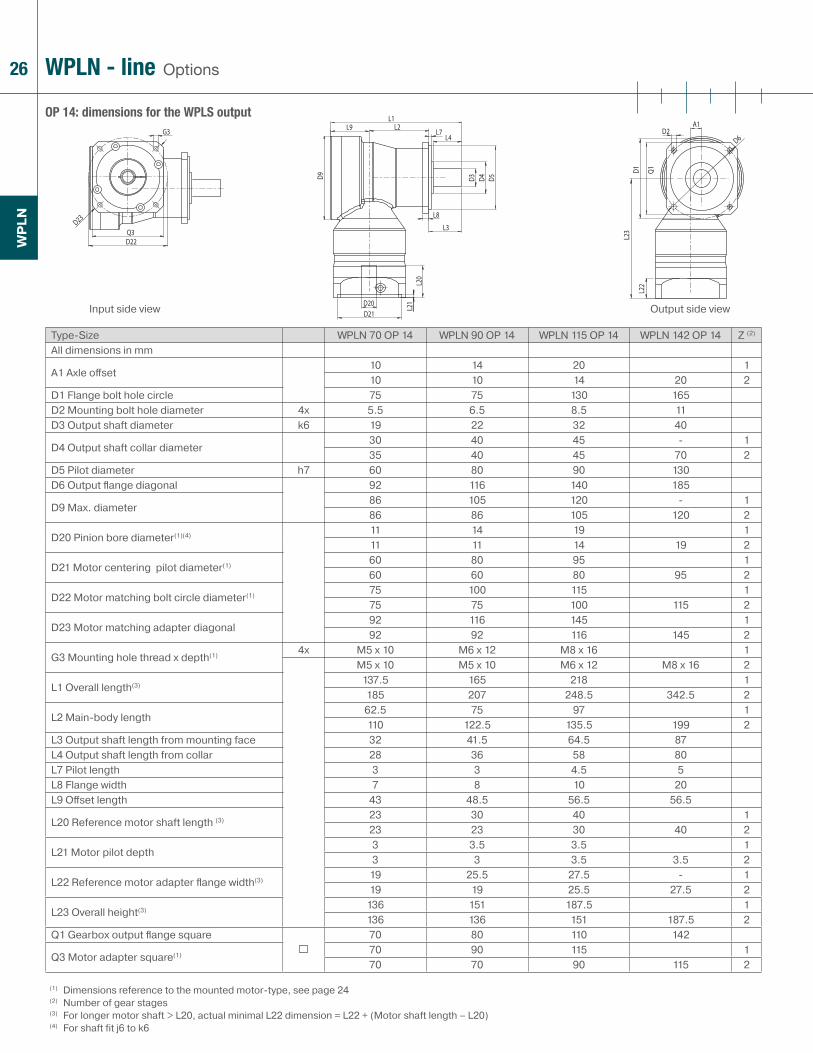
OP 14: dimensions for the WPLS output
OptionsWPLN - line
Type-Size WPLN 70 OP 14 WPLN 90 OP 14 WPLN 115 OP 14 WPLN 142 OP 14 Z (2)
All dimensions in mm
A1 Axle off set10 14 20 110 10 14 20 2
D1 Flange bolt hole circle 75 75 130 165D2 Mounting bolt hole diameter 4x 5.5 6.5 8.5 11D3 Output shaft diameter k6 19 22 32 40
D4 Output shaft collar diameter 30 40 45 - 135 40 45 70 2
D5 Pilot diameter h7 60 80 90 130D6 Output fl ange diagonal 92 116 140 185
D9 Max. diameter86 105 120 - 186 86 105 120 2
D20 Pinion bore diameter(1)(4) 11 14 19 111 11 14 19 2
D21 Motor centering pilot diameter(1) 60 80 95 160 60 80 95 2
D22 Motor matching bolt circle diameter(1) 75 100 115 175 75 100 115 2
D23 Motor matching adapter diagonal92 116 145 192 92 116 145 2
G3 Mounting hole thread x depth(1) 4x M5 x 10 M6 x 12 M8 x 16 1M5 x 10 M5 x 10 M6 x 12 M8 x 16 2
L1 Overall length(3) 137.5 165 218 1185 207 248.5 342.5 2
L2 Main-body length62.5 75 97 1110 122.5 135.5 199 2
L3 Output shaft length from mounting face 32 41.5 64.5 87L4 Output shaft length from collar 28 36 58 80L7 Pilot length 3 3 4.5 5L8 Flange width 7 8 10 20L9 Off set length 43 48.5 56.5 56.5
L20 Reference motor shaft length (3) 23 30 40 123 23 30 40 2
L21 Motor pilot depth3 3.5 3.5 13 3 3.5 3.5 2
L22 Reference motor adapter fl ange width(3) 19 25.5 27.5 - 119 19 25.5 27.5 2
L23 Overall height(3) 136 151 187.5 1136 136 151 187.5 2
Q1 Gearbox output fl ange square 70 80 110 142
Q3 Motor adapter square(1) 70 90 115 170 70 90 115 2
(1) Dimensions reference to the mounted motor-type, see page 24(2) Number of gear stages(3) For longer motor shaft > L20, actual minimal L22 dimension = L22 + (Motor shaft length – L20)(4) For shaft fit j6 to k6
Input side view Output side view

27
WP
LN
OptionsWPLN - line
Type-Size WPLN 70 OP 14 WPLN 90 OP 14 WPLN 115 OP 14 WPLN 142 OP 14 i (1)
Recommended max. mean input speed at 50% rated continuous duty torque (S1) rpmrpm(2)(3)
min-1 (rpm)
2650 2250 1600 - 43000 2700 1800 - 53850 3450 2250 - 84150 3800 2400 - 102900 2900 2400 1550 163150 3200 2700 1600 203450 3600 3100 1850 253550 3950 3450 2300 323800 4150 3600 2400 404200 4900 4350 2700 644450 5300 4700 3000 100
Type-Size WPLN 70 OP 14 WPLN 90 OP 14 WPLN 115 OP 14 WPLN 142 OP 14 i (1)
Recommended max. mean input speed at 100% rated continuous duty torque (S1) rpm(2)(3)
min-1 (rpm)
1900 1600 1100 - 42250 1950 1300 - 53200 2850 1850 - 83600 3250 2050 - 102350 2150 1700 1100 162600 2450 1950 1100 203000 2850 2400 1350 253050 3350 2850 1950 323400 3450 2950 2000 404000 4550 4000 2350 644350 5050 4450 2800 100
(1) Ratio (i=n1 rpm high speed side/n2 rpm low speed side)(2) Recommended gearbox operating temperature should not be exceeded, consult Neugart in case higher than listed rpm is required(3) Exact definition see page 81

28 WPLN - line Cross-sectional drawing
1 Output shaftMade of high-strength high quality steel for high shaft reliability
2 Output shaft bearingLarge high precision preloaded taper roller bearings for zero clearance
3 Shaft seal ringDedicated double lip seal, keeps the lubricant in, and the external contaminant out; IP 65
4 Hypoid gearGearing optimized for maximal load capacity and quiet operation
5 Hypoid pinionGearing optimized for maximal load capacity and quiet operation
6 Drive shaft bearingPretensioned precision tapered roller bearing for zero play of the drive shaft
7 Gearbox housingBlack corrosion-protected housing made of aluminium for minimal mass and optimal ease of mounting
8 Motor matching adapter plateMatches the gear head with virtually any servo motor; made of aluminum for enhanced thermal conductivity
9 CouplingBalanced coupling for high rotational speeds and strong tension force for reliable transfer of torques
10 Clamping screwHigh strength steel screw for reliable transfer of torques
1
2
3
4
56
7
8
9 10
WP
LN

29
WP
LN
additional information www.neugartusa.com
for your notes
30
PLF
N
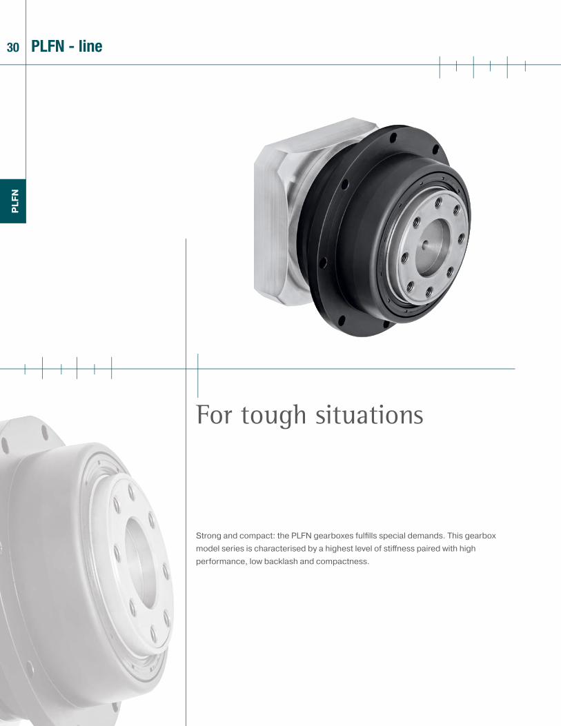
Strong and compact: the PLFN gearboxes fulfi lls special demands. This gearbox model series is characterised by a highest level of stiff ness paired with high performance, low backlash and compactness.
For tough situations
PLFN - line
31
PLF
N
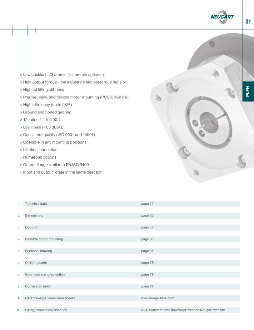
> Low backlash <3 arcmin (<1 arcmin optional)
> High output torque - the industry‘s highest torque density
> Highest tilting stiffness
> Precise, easy, and flexible motor mounting (PCS-2 system)
> High efficiency (up to 98%)
> Ground and honed gearing
> 12 ratios 4:1 to 100:1
> Low noise (<65 dB(A))
> Consistent quality (ISO 9001 and 14001)
> Operable in any mounting positions
> Lifetime lubrication
> Numerous options
> Output flange similar to EN ISO 9409
> Input and output rotate in the same direction
1 Technical data page 32
2 Dimensions page 35
3 Options page 77
4 Possible motor mounting page 36
5 Sectional drawing page 37
6 Ordering code page 76
7 Gearhead sizing/selection page 78
8 Conversion table page 77
9 CAD drawings, dimension sheets www.neugartusa.com
10 Sizing/calculation/selection NCP Software, free download from the Neugart website
32
PLF
N
Technical dataPLFN - line
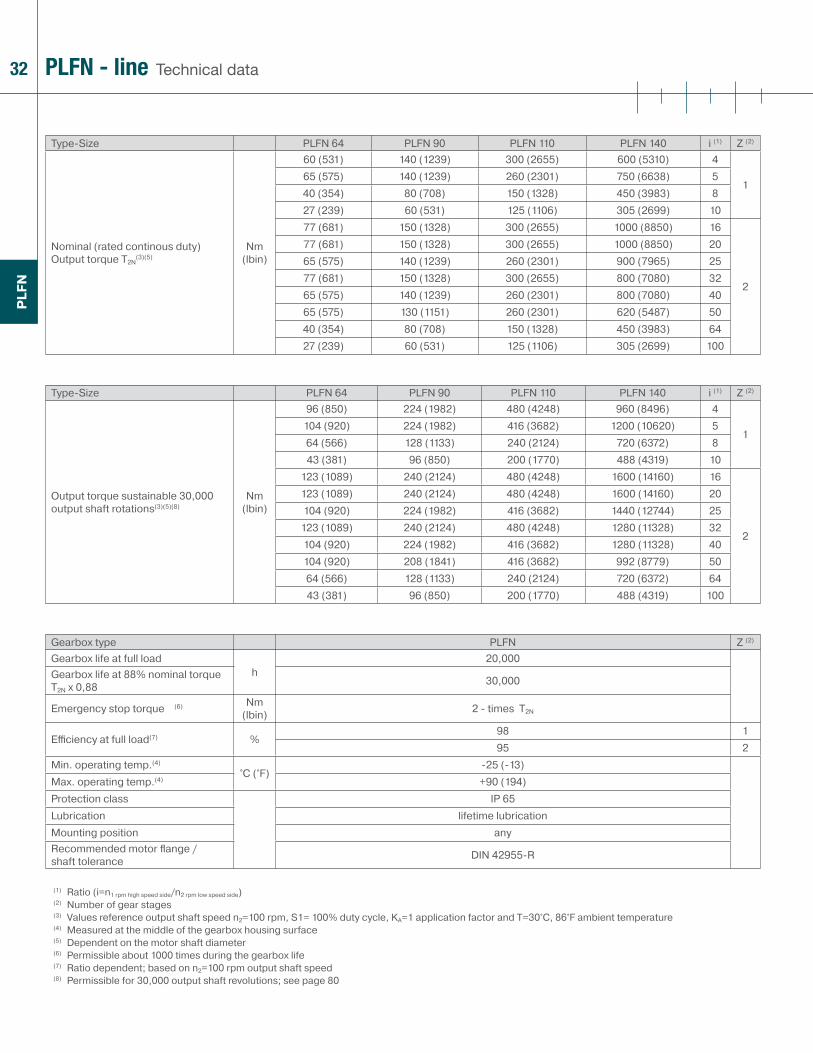
Type-Size PLFN 64 PLFN 90 PLFN 110 PLFN 140 i (1) Z (2)
Nominal (rated continous duty) Output torque T2N
(3)(5)Nm
(lbin)
60 (531) 140 (1239) 300 (2655) 600 (5310) 4
165 (575) 140 (1239) 260 (2301) 750 (6638) 540 (354) 80 (708) 150 (1328) 450 (3983) 827 (239) 60 (531) 125 (1106) 305 (2699) 1077 (681) 150 (1328) 300 (2655) 1000 (8850) 16
2
77 (681) 150 (1328) 300 (2655) 1000 (8850) 2065 (575) 140 (1239) 260 (2301) 900 (7965) 2577 (681) 150 (1328) 300 (2655) 800 (7080) 3265 (575) 140 (1239) 260 (2301) 800 (7080) 4065 (575) 130 (1151) 260 (2301) 620 (5487) 5040 (354) 80 (708) 150 (1328) 450 (3983) 6427 (239) 60 (531) 125 (1106) 305 (2699) 100
Type-Size PLFN 64 PLFN 90 PLFN 110 PLFN 140 i (1) Z (2)
Output torque sustainable 30,000 output shaft rotations(3)(5)(8)
Nm (lbin)
96 (850) 224 (1982) 480 (4248) 960 (8496) 4
1104 (920) 224 (1982) 416 (3682) 1200 (10620) 564 (566) 128 (1133) 240 (2124) 720 (6372) 843 (381) 96 (850) 200 (1770) 488 (4319) 10
123 (1089) 240 (2124) 480 (4248) 1600 (14160) 16
2
123 (1089) 240 (2124) 480 (4248) 1600 (14160) 20104 (920) 224 (1982) 416 (3682) 1440 (12744) 25
123 (1089) 240 (2124) 480 (4248) 1280 (11328) 32104 (920) 224 (1982) 416 (3682) 1280 (11328) 40104 (920) 208 (1841) 416 (3682) 992 (8779) 5064 (566) 128 (1133) 240 (2124) 720 (6372) 6443 (381) 96 (850) 200 (1770) 488 (4319) 100
Gearbox type PLFN Z (2)
Gearbox life at full load h
20,000Gearbox life at 88% nominal torque T2N x 0,88 30,000
Emergency stop torque (6) Nm (lbin) 2 - times T2N
Effi ciency at full load(7) %98 195 2
Min. operating temp.(4)
°C (°F)-25 (-13)
Max. operating temp.(4) +90 (194)Protection class IP 65Lubrication lifetime lubricationMounting position anyRecommended motor fl ange / shaft tolerance DIN 42955-R
(1) Ratio (i=n1 rpm high speed side/n2 rpm low speed side)(2) Number of gear stages(3) Values reference output shaft speed n2=100 rpm, S1= 100% duty cycle, KA=1 application factor and T=30°C, 86°F ambient temperature(4) Measured at the middle of the gearbox housing surface (5) Dependent on the motor shaft diameter (6) Permissible about 1000 times during the gearbox life(7) Ratio dependent; based on n2=100 rpm output shaft speed(8) Permissible for 30,000 output shaft revolutions; see page 80

33
PLF
N
Technical dataPLFN - line
Type-Size PLFN 64 PLFN 90 PLFN 110 PLFN 140 Z (2)
Standard backlash(7)
arcmin< 3 < 3 < 3 < 3 1< 5 < 5 < 5 < 5 2
Optional reduced backlash <2 <1 < 1 < 1Frmax. for 20,000 h(3)(4)
N (lb)
2400 (540) 4400 (990) 5500 (1238) 12000 (2700)Famax. for 20,000 h(3)(4) 4300 (968) 8200 (1845) 9500 (2138) 8500 (1913)Frmax. for 30,000 h(3)(4) 2100 (473) 3900 (878) 4800 (1080) 11000 (2475)Famax. for 30,000 h(3)(4) 3800 (855) 7200 (1620) 8400 (1890) 7500 (1688)
Torsional stiff ness Nm /arcmin (lbin /arcmin)
16 (142) 35 (310) 90 (797) 200 (1770) 114 (124) 30 (266) 80 (708) 180 (1593) 2
Weight kg (lb)1.5 (3.31) 3.0 (6.62) 6.5 (14.33) 13 (28.67) 12.2 (4.85) 4.0 (8.82) 8 (17.64) 16 (35.28) 2
Running noise(5) dB(A) < 65 < 65 < 68 < 70Max. recommended input speed(6) min-1 (rpm) 14000 10000 8500 6500
Type-Size PLFN 64 PLFN 90 PLFN 110 PLFN 140 i (1)
Recommended max. mean input speed at 50% rated continuous duty torque (S1) rpm(6)(8)
min-1 (rpm)
2450 2050 1550 1150 42800 2450 1950 1200 54100 4050 3300 2100 84850 4950 4000 2700 104300 4450 3850 2150 164800 5100 4500 2600 205400 5850 5500 3200 255900 6000 6000 4250 326000 6000 6000 4900 406000 6000 6000 5500 506000 6000 6000 5500 646000 6000 6000 5500 100
Type-Size PLFN 64 PLFN 90 PLFN 110 PLFN 140 i (1)
Recommended max. mean input speed at 100% rated continuous duty torque (S1) rpm(6)(8)
min-1 (rpm)
1950 1500 1050 800 42150 1800 1400 850 53500 3300 2650 1550 84400 4250 3350 2150 103350 3200 2550 1300 163850 3700 3050 1550 204500 4400 3900 2000 254900 5050 4400 2750 325600 5900 5500 3250 406000 6000 6000 3850 506000 6000 6000 5500 646000 6000 6000 5500 100
(1) Ratio (i=n1 rpm high speed side/n2 rpm low speed side)(2) Number of gear stages(3) Values reference output shaft speed n2=100 rpm, S1= 100% duty cycle, KA=1 application factor and T=30°C, 86°F ambient temperature(4) Reference to the rotating output flange face (5) Sound pressure level measured 1 m from the gearbox for ratio 5:1 at 3000 input rpm and no load(6) Recommended gearbox operating temperature should not be exceeded, consult Neugart in case higher than listed rpm is required(7) Lower backlash on inquiry(8) Exact definition see page 81
34
PLF
N
Technical dataPLFN - line
Type-Size PLFN 64 PLFN 90 PLFN 110 PLFN 140 i (1)
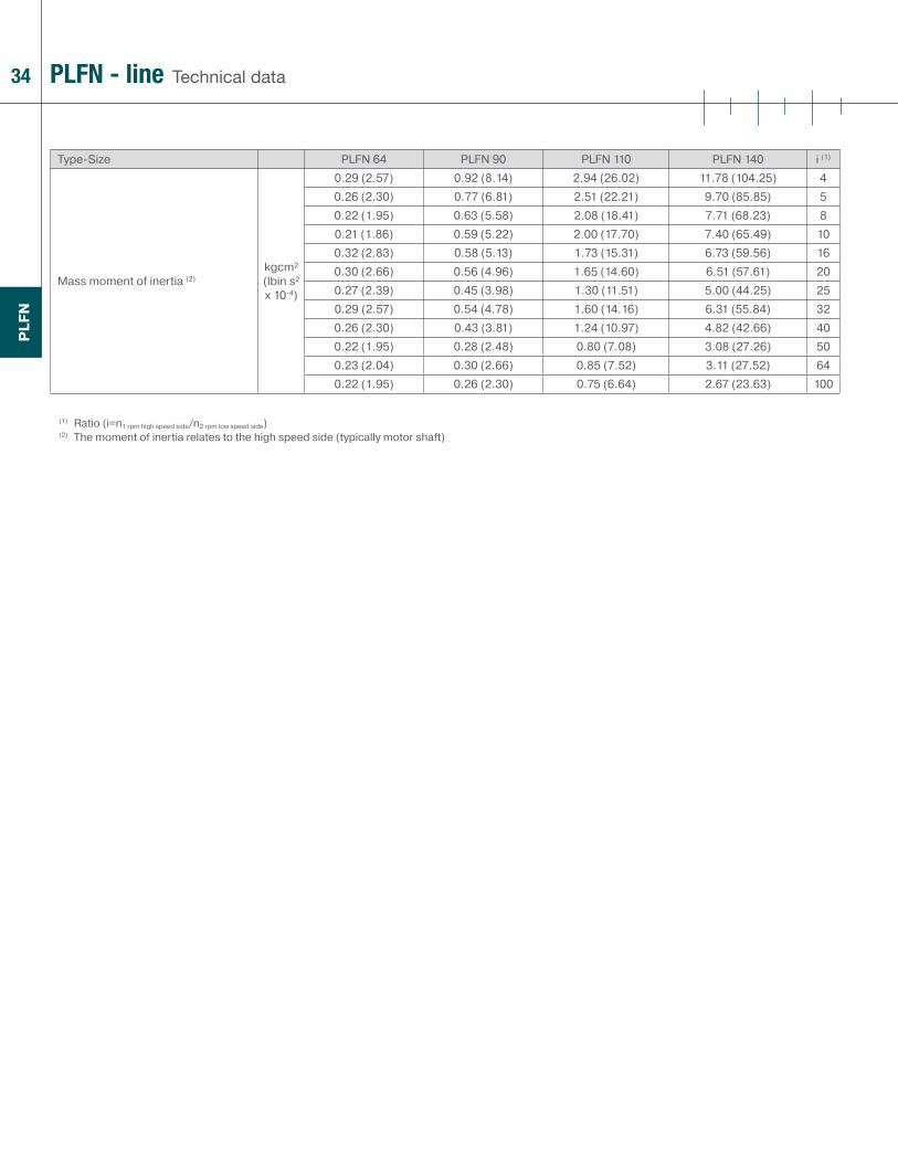
Mass moment of inertia (2)kgcm² (lbin s² x 10-4)
0.29 (2.57) 0.92 (8.14) 2.94 (26.02) 11.78 (104.25) 40.26 (2.30) 0.77 (6.81) 2.51 (22.21) 9.70 (85.85) 50.22 (1.95) 0.63 (5.58) 2.08 (18.41) 7.71 (68.23) 80.21 (1.86) 0.59 (5.22) 2.00 (17.70) 7.40 (65.49) 100.32 (2.83) 0.58 (5.13) 1.73 (15.31) 6.73 (59.56) 160.30 (2.66) 0.56 (4.96) 1.65 (14.60) 6.51 (57.61) 200.27 (2.39) 0.45 (3.98) 1.30 (11.51) 5.00 (44.25) 250.29 (2.57) 0.54 (4.78) 1.60 (14.16) 6.31 (55.84) 320.26 (2.30) 0.43 (3.81) 1.24 (10.97) 4.82 (42.66) 400.22 (1.95) 0.28 (2.48) 0.80 (7.08) 3.08 (27.26) 500.23 (2.04) 0.30 (2.66) 0.85 (7.52) 3.11 (27.52) 640.22 (1.95) 0.26 (2.30) 0.75 (6.64) 2.67 (23.63) 100
(1) Ratio (i=n1 rpm high speed side/n2 rpm low speed side)(2) The moment of inertia relates to the high speed side (typically motor shaft)
35
PLFN
PLF
N
D17
Q3
G3
D22
L22
L1L13
L12L8
L11
L10
G2
D10
D11
D12
D13
D14
L21
D21
D20
L20L5 Fw
D16
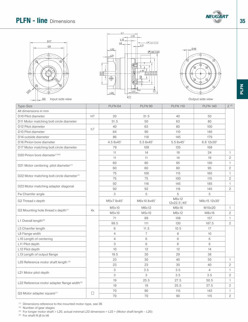
DimensionsPLFN - line
Type-Size PLFN 64 PLFN 90 PLFN 110 PLFN 140 Z (2)
All dimensions in mmD10 Pilot diameter H7 20 31.5 40 50D11 Motor matching bolt circle diameter 31.5 50 63 80D12 Pilot diameter
h740 63 80 100
D13 Pilot diameter 64 90 110 140D14 outside diameter 86 118 145 179D16 Pinion bore diameter 4.5 8x45° 5.5 8x45° 5.5 8x45° 6.6 12x30°D17 Motor matching bolt circle diameter 79 109 135 168
D20 Pinion bore diameter(1)(4)11 14 19 24 111 11 14 19 2
D21 Motor centering pilot diameter(1)60 80 95 130 160 60 80 95 2
D22 Motor matching bolt circle diameter(1)75 100 115 165 175 75 100 115 2
D23 Motor matching adapter diagonal 92 116 145 185 192 92 116 145 2
Fw Chamfer angle 3 5 5 5
G2 Thread x depth M5x7 8x45° M6x10 8x45° M6x12 12x22.5°/45° M8x15 12x30°
G3 Mounting hole thread x depth(1) 4xM5x10 M6x12 M8x16 M10x20 1M5x10 M5x10 M6x12 M8x16 2
L1 Overall length(3)71 89 108 157 1
99.5 111 130 187.5 2L5 Chamfer length 6 11.5 10.5 17L8 Flange width 4 7 8 10L10 Length of centering 4 6 6 6L11 Pilot depth 3 6 6 6L12 Pilot depth 10 12 12 14L13 Length of output fl ange 19.5 30 29 38
L20 Reference motor shaft length (3)23 30 40 50 123 23 30 40 2
L21 Motor pilot depth3 3.5 3.5 4 13 3 3.5 3.5 2
L22 Reference motor adapter fl ange width(3)19 25.5 27.5 50.5 119 19 25.5 27.5 2
Q3 Motor adapter square(1)70 90 115 142 170 70 90 115 2
(1) Dimensions reference to the mounted motor-type, see 36(2) Number of gear stages(3) For longer motor shaft > L20, actual minimal L22 dimension = L22 + (Motor shaft length – L20)(4) For shaft fit j6 to k6
Input side view Output side view
36
PLF
N
Q3
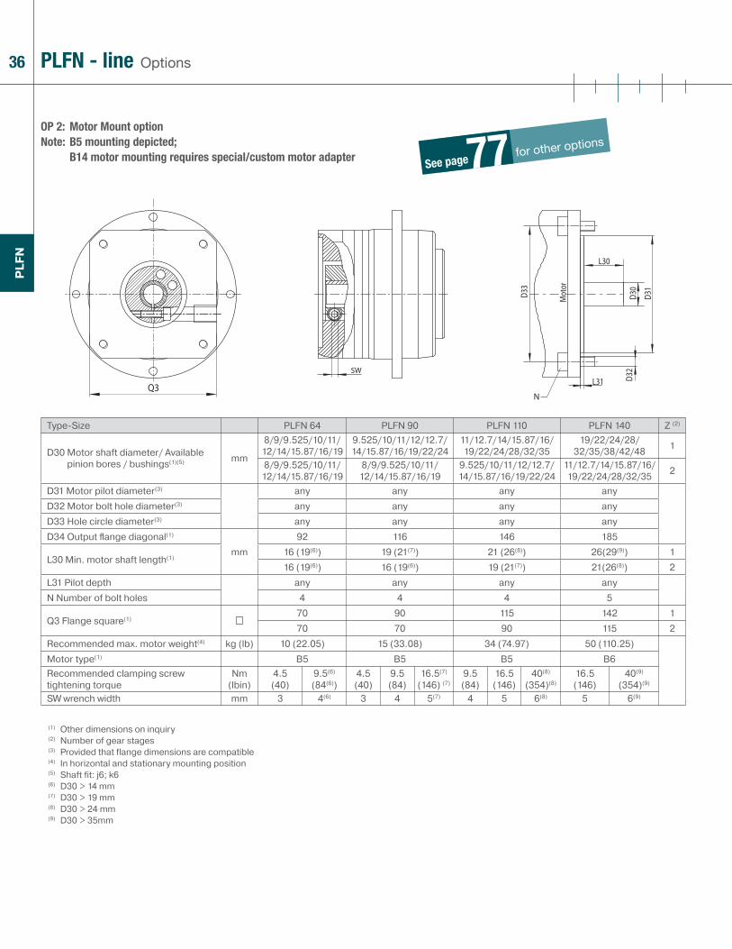
OP 2: Motor Mount option Note: B5 mounting depicted;
B14 motor mounting requires special/custom motor adapter
OptionsPLFN - line
Type-Size PLFN 64 PLFN 90 PLFN 110 PLFN 140 Z (2)
D30 Motor shaft diameter/ Available pinion bores / bushings(1)(5) mm
8/9/9.525/10/11/12/14/15.87/16/19
9.525/10/11/12/12.7/14/15.87/16/19/22/24
11/12.7/14/15.87/16/19/22/24/28/32/35
19/22/24/28/32/35/38/42/48 1
8/9/9.525/10/11/12/14/15.87/16/19
8/9/9.525/10/11/12/14/15.87/16/19
9.525/10/11/12/12.7/14/15.87/16/19/22/24
11/12.7/14/15.87/16/19/22/24/28/32/35 2
D31 Motor pilot diameter(3) any any any anyD32 Motor bolt hole diameter(3) any any any anyD33 Hole circle diameter(3) any any any anyD34 Output fl ange diagonal(1)
mm92 116 146 185
L30 Min. motor shaft length(1)16 (19(6)) 19 (21(7)) 21 (26(8)) 26(29(9)) 116 (19(6)) 16 (19(6)) 19 (21(7)) 21(26(8)) 2
L31 Pilot depth any any any anyN Number of bolt holes 4 4 4 5
Q3 Flange square(1)70 90 115 142 170 70 90 115 2
Recommended max. motor weight(4) kg (lb) 10 (22.05) 15 (33.08) 34 (74.97) 50 (110.25)Motor type(1) B5 B5 B5 B6Recommended clamping screw tightening torque
Nm (lbin)
4.5(40)
9.5(6)
(84(6))4.5(40)
9.5(84)
16.5(7)
(146) (7)9.5(84)
16.5(146)
40(8)
(354)(8)16.5(146)
40(9)
(354)(9)
SW wrench width mm 3 4(6) 3 4 5(7) 4 5 6(8) 5 6(9)
(1) Other dimensions on inquiry(2) Number of gear stages(3) Provided that flange dimensions are compatible(4) In horizontal and stationary mounting position(5) Shaft fit: j6; k6(6) D30 > 14 mm(7) D30 > 19 mm(8) D30 > 24 mm(9) D30 > 35mm
See pagefor other options 77
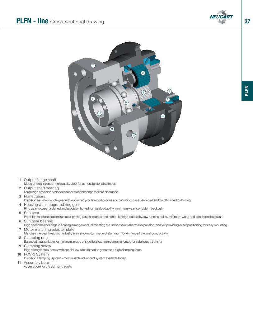
37PLFN - line Cross-sectional drawing
1 Output fl ange shaftMade of high-strength high quality steel for utmost torsional stiff ness
2 Output shaft bearingLarge high precision preloaded taper roller bearings for zero clearance
3 Planet gearsPrecision zero helix angle gear with optimized profi le modifi cations and crowning; case hardened and hard fi nished by honing
4 Housing with integrated ring gearRing gear is case hardened and precision honed for high loadability, minimum wear, consistent backlash
5 Sun gearPrecision machined optimized gear profi le, case hardened and honed for high loadability, low running noise, minimum wear, and consistent backlash
6 Sun gear bearingHigh speed ball bearings in fl oating arrangement, eliminating thrust loads from thermal expansion, and yet providing exact positioning for easy mounting
7 Motor matching adapter plateMatches the gear head with virtually any servo motor; made of aluminum for enhanced thermal conductivity
8 Clamping ringBalanced ring, suitable for high rpm, made of steel to allow high clamping forces for safe torque transfer
9 Clamping screwHigh strength steel screw with special low pitch thread to generate a high clamping force
10 PCS-2 SystemPrecision Clamping System - most reliable advanced system available today
11 Assembly boreAccess bore for the clamping screw
PLF
N
1
2
3
4
5
6
7
8
9
10
11
38
PLE
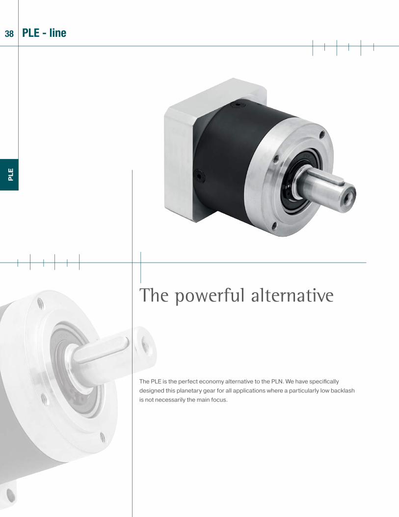
The PLE is the perfect economy alternative to the PLN. We have specifi cally designed this planetary gear for all applications where a particularly low backlash is not necessarily the main focus.
The powerful alternative
PLE - line

39
PLE
> Low backlash
> High output torque - the industry‘s highest torque density
> Precise, easy, and flexible motor mounting (PCS-2 system)
> Balanced motor pinion
> High efficiency (up to 96%)
> 22 ratios 3:1 to 512:1
> Low noise
> Consistent quality (ISO 9001 and 14001)
> Operable in any mounting positions
> Lifetime lubrication
> Numerous options
1 Technical data page 40
2 Dimensions page 48
3 Options page 77
4 Possible motor mounting page 52
5 Sectional drawing page 53
6 Ordering code page 76
7 Gearhead sizing/selection page 78
8 Conversion table page 77
9 CAD drawings, dimension sheets www.neugartusa.com
10 Sizing/calculation/selection NCP Software, free download from the Neugart website
40
PLE
Technical dataPLE - line
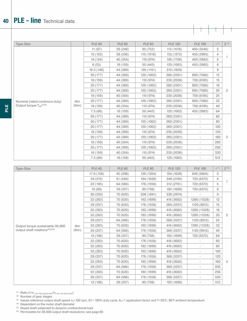
Type-Size PLE 40 PLE 60 PLE 80 PLE 120 PLE 160 i (1) Z (2)
Nominal (rated continous duty) Output torque T2N
(3)(5)Nm
(lbin)
11 (97) 28 (248) 85 (752) 115 (1018) 400 (3540) 3
115 (133) 38 (336) 115 (1018) 155 (1372) 450 (3983) 414 (124) 40 (354) 110 (974) 195 (1726) 450 (3983) 5
6 (53) 18 (159) 50 (443) 120 (1062) 450 (3983) 816.5 (146) 44 (389) 130 (1151) 210 (1859) - 9
2
20 (177) 44 (389) 120 (1062) 260 (2301) 800 (7080) 1218 (159) 44 (389) 110 (974) 230 (2036) 700 (6195) 1520 (177) 44 (389) 120 (1062) 260 (2301) 800 (7080) 1620 (177) 44 (389) 120 (1062) 260 (2301) 800 (7080) 2018 (159) 40 (354) 110 (974) 230 (2036) 700 (6195) 2520 (177) 44 (389) 120 (1062) 260 (2301) 800 (7080) 3218 (159) 40 (354) 110 (974) 230 (2036) 700 (6195) 407.5 (66) 18 (159) 50 (443) 120 (1062) 450 (3983) 6420 (177) 44 (389) 110 (974) 260 (2301) - 60
3
20 (177) 44 (389) 120 (1062) 260 (2301) - 8020 (177) 44 (389) 120 (1062) 260 (2301) - 10018 (159) 44 (389) 110 (974) 230 (2036) - 12020 (177) 44 (389) 120 (1062) 260 (2301) - 16018 (159) 40 (354) 110 (974) 230 (2036) - 20020 (177) 44 (389) 120 (1062) 260 (2301) - 25618 (159) 40 (354) 110 (974) 230 (2036) - 3207.5 (66) 18 (159) 50 (443) 120 (1062) - 512
Type-Size PLE 40 PLE 60 PLE 80 PLE 120 PLE 160 i (1) Z (2)
Output torque sustainable 30,000 output shaft rotations(3)(5)(8)
Nm (lbin)
17.6 (156) 45 (398) 136 (1204) 184 (1628) 640 (5664) 3
124 (212) 61 (540) 184 (1628) 248 (2195) 720 (6372) 422 (195) 64 (566) 176 (1558) 312 (2761) 720 (6372) 510 (89) 29 (257) 80 (708) 192 (1699) 720 (6372) 8
26 (230) 70 (620) 208 (1841) 336 (2974) - 9
2
32 (283) 70 (620) 192 (1699) 416 (3682) 1280 (11328) 1229 (257) 70 (620) 176 (1558) 368 (3257) 1120 (9912) 1532 (283) 70 (620) 192 (1699) 416 (3682) 1280 (11328) 1632 (283) 70 (620) 192 (1699) 416 (3682) 1280 (11328) 2029 (257) 64 (566) 176 (1558) 368 (3257) 1120 (9912) 2532 (283) 70 (620) 192 (1699) 416 (3682) 1280 (11328) 3229 (257) 64 (566) 176 (1558) 368 (3257) 1120 (9912) 4012 (106) 29 (257) 80 (708) 192 (1699) 720 (6372) 6432 (283) 70 (620) 176 (1558) 416 (3682) - 60
3
32 (283) 70 (620) 192 (1699) 416 (3682) - 8032 (283) 70 (620) 192 (1699) 416 (3682) - 10029 (257) 70 (620) 176 (1558) 368 (3257) - 12032 (283) 70 (620) 192 (1699) 416 (3682) - 16029 (257) 64 (566) 176 (1558) 368 (3257) - 20032 (283) 70 (620) 192 (1699) 416 (3682) - 25629 (257) 64 (566) 176 (1558) 368 (3257) - 32012 (106) 29 (257) 80 (708) 192 (1699) - 512
(1) Ratio (i=n1 rpm high speed side/n2 rpm low speed side)(2) Number of gear stages(3) Values reference output shaft speed n2=100 rpm, S1= 100% duty cycle, KA=1 application factor and T=30°C, 86°F ambient temperature(4) Dependent on the motor shaft diameter (5) Keyed shaft subjected to dynamic unidirectional load(6) Permissible for 30,000 output shaft revolutions; see page 80

41
PLE
(1) Ratio (i=n1 rpm high speed side/n2 rpm low speed side)(2) Number of gear stages(3) Values reference output shaft speed n2=100 rpm, S1= 100% duty cycle, KA=1 application factor and T=30°C, 86°F ambient temperature(4) Dependent on the motor shaft diameter (5) Keyed shaft subjected to dynamic unidirectional load(6) Permissible for 30,000 output shaft revolutions; see page 80
Technical dataPLE - line
Type-Size PLE 60/70 PLE 80/90 PLE 120/115 i (1) Z (2)
Nominal (rated continous duty) Output torque T2N
(3)(5)Nm
(lbin)
28 (248) 85 (752) 115 (1018) 3
138 (336) 115 (1018) 155 (1372) 440 (354) 110 (974) 195 (1726) 518 (159) 50 (443) 120 (1062) 844 (389) 130 (1151) 210 (1859) 9
2
44 (389) 120 (1062) 260 (2301) 1244 (389) 110 (974) 230 (2036) 1544 (389) 120 (1062) 260 (2301) 1644 (389) 120 (1062) 260 (2301) 2040 (354) 110 (974) 230 (2036) 2544 (389) 120 (1062) 260 (2301) 3240 (354) 110 (974) 230 (2036) 4018 (159) 50 (443) 120 (1062) 6444 (389) 110 (974) 260 (2301) 60
3
44 (389) 120 (1062) 260 (2301) 8044 (389) 120 (1062) 260 (2301) 10044 (389) 110 (974) 230 (2036) 12044 (389) 120 (1062) 260 (2301) 16040 (354) 110 (974) 230 (2036) 20044 (389) 120 (1062) 260 (2301) 25640 (354) 110 (974) 230 (2036) 32018 (159) 50 (443) 120 (1062) 512
Type-Size PLE 60/70 PLE 80/90 PLE 120/115 i (1) Z (2)
Output torque sustainable 30,000 output shaft rotations(3)(5)(8)
Nm (lbin)
45 (398) 136 (1204) 184 (1628) 3
161 (540) 184 (1628) 248 (2195) 464 (566) 176 (1558) 312 (2761) 529 (257) 80 (708) 192 (1699) 870 (620) 208 (1841) 336 (2974) 9
2
70 (620) 192 (1699) 416 (3682) 1270 (620) 176 (1558) 368 (3257) 1570 (620) 192 (1699) 416 (3682) 1670 (620) 192 (1699) 416 (3682) 2064 (566) 176 (1558) 368 (3257) 2570 (620) 192 (1699) 416 (3682) 3264 (566) 176 (1558) 368 (3257) 4029 (257) 80 (708) 192 (1699) 6470 (620) 176 (1558) 416 (3682) 60
3
70 (620) 192 (1699) 416 (3682) 8070 (620) 192 (1699) 416 (3682) 10070 (620) 176 (1558) 368 (3257) 12070 (620) 192 (1699) 416 (3682) 16064 (566) 176 (1558) 368 (3257) 20070 (620) 192 (1699) 416 (3682) 25664 (566) 176 (1558) 368 (3257) 32029 (257) 80 (708) 192 (1699) 512

42
PLE
Technical dataPLE - line
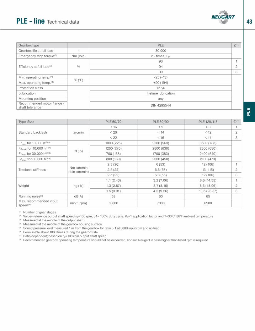
Gearbox type PLE Z (1)
Gearbox life at full load h 30,000Emergency stop torque(6) Nm (lbin) 2 - times T2N
Effi ciency at full load(7) %96 194 290 3
Min. operating temp.(4)
°C (°F)-25 (-13)
Max. operating temp.(4) +90 (194)Protection class IP 54Lubrication lifetime lubricationMounting position anyRecommended motor fl ange / shaft tolerance DIN 42955-N
Type-Size PLE 40 PLE 60 PLE 80 PLE 120 PLE 160 Z (1)
Standard backlash arcmin< 24 < 16 < 9 < 8 < 6 1< 28 < 20 < 14 < 12 < 10 2< 30 < 22 < 16 < 14 - 3
Frmax. for 10,000 h(3)(4)
N (lb)
200 (45) 500 (113) 950 (214) 2000 (450) 6000 (1350)Famax. for 10,000 h(3)(4) 200 (45) 600 (135) 1200 (270) 2800 (630) 8000 (1800)Frmax. for 30,000 h(3)(4) 160 (36) 340 (77) 650 (146) 1500 (338) 4200 (945)Famax. for 30,000 h(3)(4) 160 (36) 450 (101) 900 (203) 2100 (473) 6000 (1350)
Torsional stiff ness Nm /arcmin (lbin /arcmin)
1.0 (9) 2.3 (20) 6 (53) 12 (106) 38 (336) 11.1 (10) 2.5 (22) 6.5 (58) 13 (115) 41 (363) 21.0 (9) 2.5 (22) 6.3 (56) 12 (106) 3
Weight kg (lb)0.35 (0.77) 0.9 (1.98) 2.1 (4.63) 6.0 (13.23) 18 (39.69) 10.45 (0.99) 1.1 (2.43) 2.6 (5.73) 8.0 (17.64) 22 (48.51) 20.55 (1.21) 1.3 (2.87) 3.1 (6.84) 10.0 (22.05) 3
Running noise(5) dB(A) 58 58 60 65 70Max. recommended input speed(6) min-1 (rpm) 18000 13000 7000 6500 6500
(1) Number of gear stages(2) Values reference output shaft speed n2=100 rpm, S1= 100% duty cycle, KA=1 application factor and T=30°C, 86°F ambient temperature(3) Measured at the middle of the output shaft(4) Measured at the middle of the gearbox housing surface(5) Sound pressure level measured 1 m from the gearbox for ratio 5:1 at 3000 input rpm and no load(6) Permissible about 1000 times during the gearbox life(7) Ratio dependent; based on n2=100 rpm output shaft speed(8) Recommended gearbox operating temperature should not be exceeded, consult Neugart in case higher than listed rpm is required
43
PLE
Technical dataPLE - line
Gearbox type PLE Z (1)
Gearbox life at full load h 30,000Emergency stop torque(6) Nm (lbin) 2 - times T2N
Effi ciency at full load(7) %96 194 290 3
Min. operating temp.(4)
°C (°F)-25 (-13)
Max. operating temp.(4) +90 (194)Protection class IP 54Lubrication lifetime lubricationMounting position anyRecommended motor fl ange / shaft tolerance DIN 42955-N
Type-Size PLE 60/70 PLE 80/90 PLE 120/115 Z (1)
Standard backlash arcmin< 16 < 9 < 8 1< 20 < 14 < 12 2< 22 < 16 < 14 3
Frmax. for 10,000 h(3)(4)
N (lb)
1000 (225) 2500 (563) 3500 (788)Famax. for 10,000 h(3)(4) 1200 (270) 2800 (630) 2800 (630)Frmax. for 30,000 h(3)(4) 700 (158) 1700 (383) 2400 (540)Famax. for 30,000 h(3)(4) 800 (180) 2000 (450) 2100 (473)
Torsional stiff ness Nm /arcmin (lbin /arcmin)
2.3 (20) 6 (53) 12 (106) 12.5 (22) 6.5 (58) 13 (115) 22.5 (22) 6.3 (56) 12 (106) 3
Weight kg (lb)1.1 (2.43) 3.2 (7.06) 6.6 (14.55) 11.3 (2.87) 3.7 (8.16) 8.6 (18.96) 21.5 (3.31) 4.2 (9.26) 10.6 (23.37) 3
Running noise(5) dB(A) 58 60 65Max. recommended input speed(6) min-1 (rpm) 13000 7000 6500
(1) Number of gear stages(2) Values reference output shaft speed n2=100 rpm, S1= 100% duty cycle, KA=1 application factor and T=30°C, 86°F ambient temperature(3) Measured at the middle of the output shaft(4) Measured at the middle of the gearbox housing surface(5) Sound pressure level measured 1 m from the gearbox for ratio 5:1 at 3000 input rpm and no load(6) Permissible about 1000 times during the gearbox life(7) Ratio dependent; based on n2=100 rpm output shaft speed(8) Recommended gearbox operating temperature should not be exceeded, consult Neugart in case higher than listed rpm is required

44
PLE
Technical dataPLE - line
Type-Size PLE 40 PLE 60 PLE 80 PLE 120 PLE 160 i (1)
Recommended max. mean input speed at 50% rated continuous duty torque (S1) rpm(2)(3)
min-1 (rpm)
5000 4500 3900 3500 1700 35000 4500 3650 3500 1700 45000 4500 4000 3500 2000 55000 4500 4000 3500 2900 85000 4500 4000 3500 - 95000 4500 4000 3500 1950 125000 4500 4000 3500 2600 155000 4500 4000 3500 2300 165000 4500 4000 3500 2700 205000 4500 4000 3500 3000 255000 4500 4000 3500 3000 325000 4500 4000 3500 3000 405000 4500 4000 3500 - 605000 4500 4000 3500 3000 645000 4500 4000 3500 - 805000 4500 4000 3500 - 1005000 4500 4000 3500 - 1205000 4500 4000 3500 - 1605000 4500 4000 3500 - 2005000 4500 4000 3500 - 2565000 4500 4000 3500 - 3205000 4500 4000 3500 - 512
Type-Size PLE 40 PLE 60 PLE 80 PLE 120 PLE 160 i (1)
Recommended max. mean input speed at 100% rated continuous duty torque (S1) rpm(2)(3)
min-1 (rpm)
5000 4450 2400 2500 1000 35000 4400 2150 2250 1000 45000 4500 2650 2250 1150 55000 4500 4000 3500 1750 85000 4500 2700 2500 - 95000 4500 3450 2500 1050 125000 4500 4000 3250 1450 155000 4500 4000 3000 1200 165000 4500 4000 3500 1500 205000 4500 4000 3500 2050 255000 4500 4000 3500 2250 325000 4500 4000 3500 2950 405000 4500 4000 3500 - 605000 4500 4000 3500 3000 645000 4500 4000 3500 - 805000 4500 4000 3500 - 1005000 4500 4000 3500 - 1205000 4500 4000 3500 - 1605000 4500 4000 3500 - 2005000 4500 4000 3500 - 2565000 4500 4000 3500 - 3205000 4500 4000 3500 - 512
(1) Ratio (i=n1 rpm high speed side/n2 rpm low speed side)(2) Recommended gearbox operating temperature should not be exceeded, consult Neugart in case higher than listed rpm is required(3) Exact definition see page 81

45
PLE
(1) Ratio (i=n1 rpm high speed side/n2 rpm low speed side)(2) Recommended gearbox operating temperature should not be exceeded, consult Neugart in case higher than listed rpm is required(3) Exact definition see page 81
Technical dataPLE - line
Type-Size PLE 60/70 PLE 80/90 PLE 120/115 i (1)
Recommended max. mean input speed at 50% rated continuous duty torque (S1) rpm(2)(3)
min-1 (rpm)
4500 3350 3500 34500 3250 3500 44500 3900 3500 54500 4000 3500 84500 4000 3500 94500 4000 3500 124500 4000 3500 154500 4000 3500 164500 4000 3500 204500 4000 3500 254500 4000 3500 324500 4000 3500 404500 4000 3500 604500 4000 3500 644500 4000 3500 804500 4000 3500 1004500 4000 3500 1204500 4000 3500 1604500 4000 3500 2004500 4000 3500 2564500 4000 3500 3204500 4000 3500 512
Type-Size PLE 60/70 PLE 80/90 PLE 120/115 i (1)
Recommended max. mean input speed at 100% rated continuous duty torque (S1) rpm(2)(3)
min-1 (rpm)
3900 2200 2500 33900 2000 2250 44350 2450 2250 54500 4000 3500 84500 2600 2500 94500 3350 2500 124500 4000 3250 154500 4000 3000 164500 4000 3500 204500 4000 3500 254500 4000 3500 324500 4000 3500 404500 4000 3500 604500 4000 3500 644500 4000 3500 804500 4000 3500 1004500 4000 3500 1204500 4000 3500 1604500 4000 3500 2004500 4000 3500 2564500 4000 3500 3204500 4000 3500 512

46
PLE
Technical dataPLE - line
Type-Size PLE 40 PLE 60 PLE 80 PLE 120 PLE 160 i (1)
Mass moment of inertia (2) kgcm² (lbin s² x 10-4)
0.031 (0.27) 0.135 (1.19) 0.77 (6.81) 2.63 (23.28) 12.14 (107.44) 30.022 (0.19) 0.093 (0.82) 0.52 (4.60) 1.79 (15.84) 7.78 (68.85) 40.019 (0.17) 0.078 (0.69) 0.45 (3.98) 1.53 (13.54) 6.07 (53.72) 50.017 (0.15) 0.065 (0.58) 0.39 (3.45) 1.32 (11.68) 4.63 (40.98) 80.030 (0.27) 0.131 (1.16) 0.74 (6.55) 2.62 (23.19) - 90.029 (0.26) 0.127 (1.12) 0.72 (6.37) 2.56 (22.66) 12.37 (109.47) 120.023 (0.20) 0.077 (0.68) 0.71 (6.28) 2.53 (22.39) 12.35 (109.30) 150.022 (0.19) 0.088 (0.78) 0.50 (4.43) 1.75 (15.49) 7.47 (66.11) 160.019 (0.17) 0.075 (0.66) 0.44 (3.89) 1.50 (13.28) 6.65 (58.85) 200.019 (0.17) 0.075 (0.66) 0.44 (3.89) 1.49 (13.19) 5.81 (51.42) 250.017 (0.15) 0.064 (0.57) 0.39 (3.45) 1.30 (11.51) 6.36 (56.29) 320.016 (0.14) 0.064 (0.57) 0.39 (3.45) 1.30 (11.51) 5.28 (46.73) 400.029 (0.26) 0.076 (0.67) 0.51 (4.51) 2.57 (22.74) - 600.016 (0.14) 0.064 (0.57) 0.39 (3.45) 1.30 (11.51) 4.50 (39.83) 640.019 (0.17) 0.075 (0.66) 0.50 (4.43) 1.50 (13.28) - 800.019 (0.17) 0.075 (0.66) 0.44 (3.89) 1.49 (13.19) - 1000.029 (0.26) 0.064 (0.57) 0.70 (6.20) 2.50 (22.13) - 1200.016 (0.14) 0.064 (0.57) 0.39 (3.45) 1.30 (11.51) - 1600.016 (0.14) 0.064 (0.57) 0.39 (3.45) 1.30 (11.51) - 2000.016 (0.14) 0.064 (0.57) 0.39 (3.45) 1.30 (11.51) - 2560.016 (0.14) 0.064 (0.57) 0.39 (3.45) 1.30 (11.51) - 3200.016 (0.14) 0.064 (0.57) 0.39 (3.45) 1.30 (11.51) - 512
(1) Ratio (i=n1 rpm high speed side/n2 rpm low speed side)(2) The moment of inertia relates to the high speed side (typically motor shaft)
47
PLE
Technical dataPLE - line
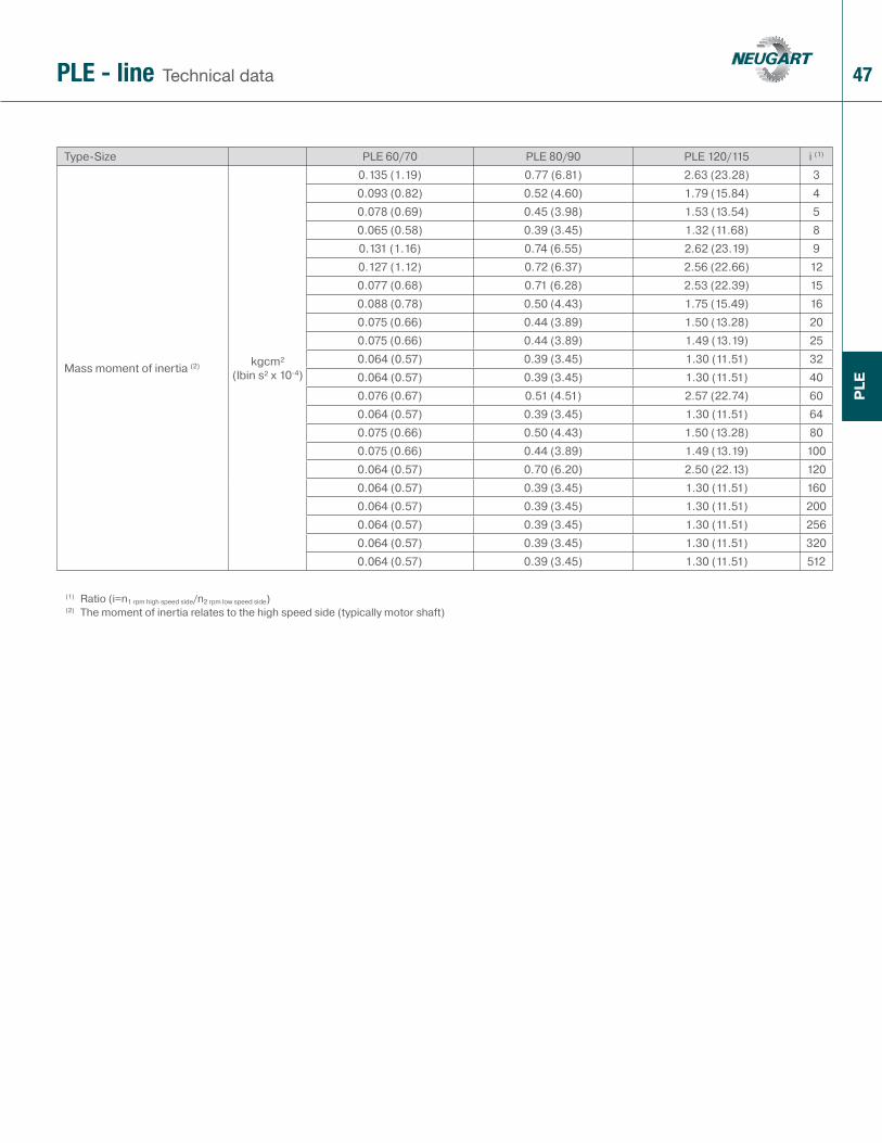
Type-Size PLE 60/70 PLE 80/90 PLE 120/115 i (1)
Mass moment of inertia (2) kgcm² (lbin s² x 10-4)
0.135 (1.19) 0.77 (6.81) 2.63 (23.28) 30.093 (0.82) 0.52 (4.60) 1.79 (15.84) 40.078 (0.69) 0.45 (3.98) 1.53 (13.54) 50.065 (0.58) 0.39 (3.45) 1.32 (11.68) 80.131 (1.16) 0.74 (6.55) 2.62 (23.19) 90.127 (1.12) 0.72 (6.37) 2.56 (22.66) 120.077 (0.68) 0.71 (6.28) 2.53 (22.39) 150.088 (0.78) 0.50 (4.43) 1.75 (15.49) 160.075 (0.66) 0.44 (3.89) 1.50 (13.28) 200.075 (0.66) 0.44 (3.89) 1.49 (13.19) 250.064 (0.57) 0.39 (3.45) 1.30 (11.51) 320.064 (0.57) 0.39 (3.45) 1.30 (11.51) 400.076 (0.67) 0.51 (4.51) 2.57 (22.74) 600.064 (0.57) 0.39 (3.45) 1.30 (11.51) 640.075 (0.66) 0.50 (4.43) 1.50 (13.28) 800.075 (0.66) 0.44 (3.89) 1.49 (13.19) 1000.064 (0.57) 0.70 (6.20) 2.50 (22.13) 1200.064 (0.57) 0.39 (3.45) 1.30 (11.51) 1600.064 (0.57) 0.39 (3.45) 1.30 (11.51) 2000.064 (0.57) 0.39 (3.45) 1.30 (11.51) 2560.064 (0.57) 0.39 (3.45) 1.30 (11.51) 3200.064 (0.57) 0.39 (3.45) 1.30 (11.51) 512
(1) Ratio (i=n1 rpm high speed side/n2 rpm low speed side)(2) The moment of inertia relates to the high speed side (typically motor shaft)
48
PLE
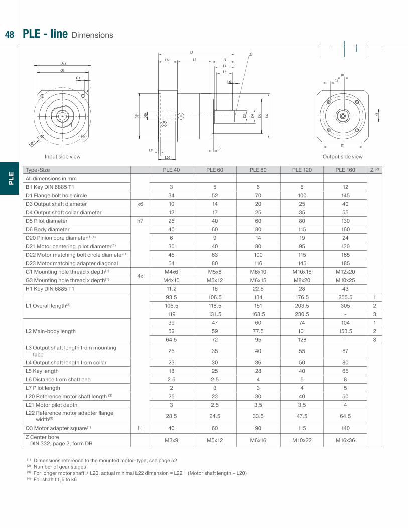
DimensionsPLE - line
Type-Size PLE 40 PLE 60 PLE 80 PLE 120 PLE 160 Z (2)
All dimensions in mmB1 Key DIN 6885 T1 3 5 6 8 12D1 Flange bolt hole circle 34 52 70 100 145D3 Output shaft diameter k6 10 14 20 25 40D4 Output shaft collar diameter 12 17 25 35 55D5 Pilot diameter h7 26 40 60 80 130D6 Body diameter 40 60 80 115 160D20 Pinion bore diameter(1)(4) 6 9 14 19 24D21 Motor centering pilot diameter(1) 30 40 80 95 130D22 Motor matching bolt circle diameter(1) 46 63 100 115 165D23 Motor matching adapter diagonal 54 80 116 145 185G1 Mounting hole thread x depth(1)
4xM4x6 M5x8 M6x10 M10x16 M12x20
G3 Mounting hole thread x depth(1) M4x10 M5x12 M6x15 M8x20 M10x25H1 Key DIN 6885 T1 11.2 16 22.5 28 43
L1 Overall length(3)
93.5 106.5 134 176.5 255.5 1106.5 118.5 151 203.5 305 2
119 131.5 168.5 230.5 - 3
L2 Main-body length39 47 60 74 104 152 59 77.5 101 153.5 2
64.5 72 95 128 - 3L3 Output shaft length from mounting
face 26 35 40 55 87
L4 Output shaft length from collar 23 30 36 50 80L5 Key length 18 25 28 40 65L6 Distance from shaft end 2.5 2.5 4 5 8L7 Pilot length 2 3 3 4 5L20 Reference motor shaft length (3) 25 23 30 40 50L21 Motor pilot depth 3 2.5 3.5 3.5 4L22 Reference motor adapter fl ange
width(3) 28.5 24.5 33.5 47.5 64.5
Q3 Motor adapter square(1) 40 60 90 115 140
Z Center bore DIN 332, page 2, form DR M3x9 M5x12 M6x16 M10x22 M16x36
(1) Dimensions reference to the mounted motor-type, see page 52(2) Number of gear stages(3) For longer motor shaft > L20, actual minimal L22 dimension = L22 + (Motor shaft length – L20)(4) For shaft fit j6 to k6
Input side view Output side view

49
PLE
DimensionsPLE - line
Type-Size PLE 60/70 PLE 80/90 PLE 120/115 Z (2)
All dimensions in mmB1 Key DIN 6885 T1 5 6 8D1 Flange bolt hole circle 75 100 130D2 Mounting bolt hole diameter 4x 5.5 6.5 8.5D3 Output shaft diameter k6 16 20 25D4 Output shaft collar diameter 20 35 35D5 Pilot diameter h7 60 80 110D6 Body diameter 60 80 115D20 Pinion bore diameter(1)(4) 9 14 19D21 Motor centering pilot diameter(1) 40 80 95D22 Motor matching bolt circle diameter(1) 63 100 115D23 Motor matching adapter diagonal 80 116 145G3 Mounting hole thread x depth(1) 4x M5x8 M6x15 M8x20H1 Key DIN 6885 T1 18 22.5 28
L1 Overall length(3)
111.5 145 201.5 1124 162 228.5 2
136.5 179.5 255.5 3
L2 Main-body length55 71.5 99 1
67.5 88.5 126 280 106 153 3
L3 Output shaft length from mounting face 32 40 55
L4 Output shaft length from collar 28 36 50L5 Key length 20 28 40L6 Distance from shaft end 4 4 5L7 Pilot length 3 3 4L8 Flange width 10 10 15L20 Reference motor shaft length (3) 23 30 40L21 Motor pilot depth 2.5 3.5 3.5L22 Reference motor adapter fl ange
width(3) 24.5 33.5 47.5
Q1 Motor adapter square 70 90 115Q3 Motor adapter square(1) 60 90 115Z Center bore
DIN 332, page 2, form DR M5x12 M6x16 M10x22
(1) Dimensions reference to the mounted motor-type, see page 52(2) Number of gear stages(3) For longer motor shaft > L20, actual minimal L22 dimension = L22 + (Motor shaft length – L20)(4) For shaft fit j6 to k6
Input side view Output side view

50
PLE
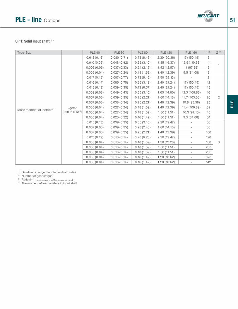
OP 1: Solid input shaft (1)
OptionsPLE - line
Type-Size PLE 40 PLE 60-60/70 PLE 80-80/90 PLE 120-120/115 PLE 160 Z (2)
B2 Key DIN 6885 T1mm
2 3 5 6 10D6 Flange diameter 40 60 80 115 160D40 Output shaft diameter j6 8 10 16 20 35D41 Output shaft collar diameter mm 12 17 25 35 55D42 Pilot diameter h7 26 40 60 80 110D43 Flange bolt hole circle mm 34 52 70 100 130G5 Mounting hole thread x depth 4x M4x6 M5x8 M6x10 M10x16 M10x25H2 Key DIN 6885 T1
mm
8.8 11.2 18 22.5 38L2 Main-body length page 48 page 48 page 48 page 48 page 48 1L40 Shaft length from input face 20 28 30 45 65L41 Output shaft length from collar 17 23 26 40 58L42 Pilot depth length 2 3 3 4 5L43 Key length 12 18 20 32 45L44 Distance from shaft end 2.5 2.5 3 4 7L45 Input fl ange length 10.2 12.7 15 31 58Max. recommended input speed(5)
min-1 (rpm)
18000 13000 7000 6500 4500Recommended max. mean input speed(3)(5) page 44 page 44 page 44 page 44 page 44
Input shaft load axial(4)
N (lb)120 (27) 300 (68) 500 (113) 1300 (293) 1600 (360)
Input shaft load radial(4) 100 (23) 250 (56) 450 (101) 1000 (225) 1400 (315)Z Center bore
DIN 332, page 2, form DR 4x M3x9 M3x9 M5x12 M6x16 M12x28
(1) Gearbox is flange mounted on both sides (2) Number of gear stages(3) These values refer to S1 - duty cycle and ambient temperature 20° C(4) At the midpoint of the shaft n1=1000 min-1 referred to 10,000 h lifetime(5) Recommended operating temperature should not be exceeded
51
PLE
PLE
OP 1: Solid input shaft (1 )
OptionsPLE - line
Type-Size PLE 40 PLE 60 PLE 80 PLE 120 PLE 160 i (3) Z (2)
Mass moment of inertia (4 ) kgcm² (lbin s² x 10-4)
0.018 (0.16) 0.080 (0.71) 0.73 (6.46) 2.30 (20.36) 17 (150.45) 3
10.010 (0.09) 0.048 (0.42) 0.35 (3.10) 1.85 (16.37) 12.5 (110.63) 40.006 (0.05) 0.037 (0.33) 0.24 (2.12) 1.42 (12.57) 11 (97.35) 50.005 (0.04) 0.027 (0.24) 0.18 (1.59) 1.40 (12.39) 9.5 (84.08) 80.017 (0.15) 0.087 (0.77) 0.73 (6.46) 2.50 (22.13) - 9
2
0.016 (0.14) 0.085 (0.75) 0.36 (3.19) 2.40 (21.24) 17 (150.45) 120.015 (0.13) 0.039 (0.35) 0.72 (6.37) 2.40 (21.24) 17 (150.45) 150.009 (0.08) 0.049 (0.43) 0.35 (3.10) 1.65 (14.60) 12.3 (108.86) 160.007 (0.06) 0.039 (0.35) 0.25 (2.21) 1.60 (14.16) 11.7 (103.55) 200.007 (0.06) 0.038 (0.34) 0.25 (2.21) 1.40 (12.39) 10.8 (95.58) 250.005 (0.04) 0.027 (0.24) 0.18 (1.59) 1.40 (12.39) 11.4 (100.89) 320.005 (0.04) 0.027 (0.24) 0.18 (1.59) 1.30 (11.51) 10.3 (91.16) 400.005 (0.04) 0.025 (0.22) 0.16 (1.42) 1.30 (11.51) 9.5 (84.08) 640.015 (0.13) 0.039 (0.35) 0.35 (3.10) 2.20 (19.47) - 60
3
0.007 (0.06) 0.039 (0.35) 0.28 (2.48) 1.60 (14.16) - 800.007 (0.06) 0.039 (0.35) 0.25 (2.21) 1.40 (12.39) - 1000.013 (0.12) 0.016 (0.14) 0.70 (6.20) 2.20 (19.47) - 1200.005 (0.04) 0.016 (0.14) 0.18 (1.59) 1.50 (13.28) - 1600.005 (0.04) 0.016 (0.14) 0.18 (1.59) 1.30 (11.51) - 2000.005 (0.04) 0.016 (0.14) 0.18 (1.59) 1.30 (11.51) - 2560.005 (0.04) 0.016 (0.14) 0.16 (1.42) 1.20 (10.62) - 3200.005 (0.04) 0.016 (0.14) 0.16 (1.42) 1.20 (10.62) - 512
(1) Gearbox is flange mounted on both sides(2) Number of gear stages(3) Ratio (i=n1 rpm high speed side/n2 rpm low speed side)(4) The moment of inertia refers to input shaft

52
PLE
B5
B14
OP 2: Motor Mount option Note: B5 mounting depicted;
B14 motor mounting requires special/custom motor adapter
OptionsPLE - line
Type-Size PLE 40 PLE 60 PLE 80 PLE 120 PLE 160 Z (2)
D4 Motor mounting hole diameter(3) any any any any any
D30 Motor shaft diameter/ Available pinion bores / bushings(1)(5) mm 4/5/6/6.35/
8/9/11
6/6.35/8/9/9.525/11/12/15.87/14/16/19
9.525/10/11/12/12.7/14/15.87/
16/19/22/24
11/12.7/14/15.87/16/19/
22/24/28/32/35
19/24/28/32/35
D31 Motor pilot diameter(3) any any any any anyD32 Motor bolt hole diameter(3) any any any any anyD33 Hole circle diameter(3) any any any any anyD34 Output fl ange diagonal(1) mm 54 80 116 145 185G4 Motor mounting thread size any any any any anyL30 Min. motor shaft length(1) mm 12.5 (16(6)) 16 (19(7)) 19 (21(8)) 21 (26(9)) 26L31 Pilot depth any any any any anyN Number of bolt holes 4 4 4 4 4
Q3 Flange square(1) 40 60 80 115 140
Recommended max. motor weight(4) kg (lb) 2 (4.41) 3.5 (7.72) 9 (19.85) 16.5 (36.38) 40 (88.20)Motor type(1) B5/B14 B5/B14 B5/B14 B5/B14 B5/B14Recommended clamping screw tightening torque
Nm (lbin)
2(18)
4.5(40)
4.5(40)
9.5(84)
9.5(84)
16.5(146)
16.5(146)
40(354)
40 (354)
SW wrench width mm 2.5 3 3 4 4 5 5 6 6
(1) Other dimensions on inquiry(2) Number of gear stages(3) Provided that flange dimensions are compatible(4) In horizontal and stationary mounting position(5) Shaft fit: j6; k6(6) D30 > 9 mm(7) D30 > 14 mm(8) D30 > 19 mm(9) D30 > 24 mm
See pagefor other options 77

53
12
3
4
5
6
7
8
9
10
11
PLE - line Cross-sectional drawing
1 Output shaftMade of high-strength high quality steel for high shaft reliability
2 Output shaft bearingDeep groove ball bearings with contact seals
3 Planet gearsPrecision zero helix angle gear with optimized profi le modifi cations and crowning; case hardened and hard fi nished by honing
4 Housing with integrated ring gearRing gear is case hardened and precision honed for high loadability, minimum wear, consistent backlash
5 Sun gearPrecision machined optimized gear profi le, case hardened and honed for high loadability, low running noise, minimum wear, and consistent backlash
6 Sun gear bearingHigh speed ball bearings in fl oating arrangement, eliminating thrust loads from thermal expansion, and yet providing exact positioning for easy mounting
7 Motor matching adapter plateMatches the gear head with virtually any servo motor; made of aluminum for enhanced thermal conductivity
8 Clamping ringBalanced ring, suitable for high rpm, made of steel to allow high clamping forces for safe torque transfer
9 Clamping screwHigh strength steel screw with special low pitch thread to generate a high clamping force
10 PCS SystemPatented multiple closed slot Precision Clamping System - most reliable advanced system available today
11 Assembly boreAccess bore for the clamping screw
PLE

54
WPL
E
The WPLE is the logical refi nement of our PLE series. This bevel gearbox series was designed especially for space-saving installation in a right-angle position of the motor/gearbox combination.
For new perspectives
WPLE - line
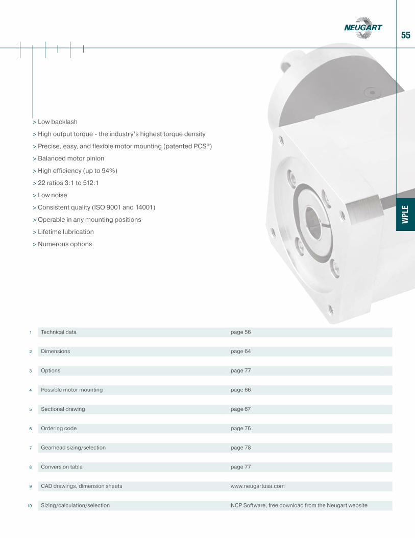
55
WPL
E
1 Technical data page 56
2 Dimensions page 64
3 Options page 77
4 Possible motor mounting page 66
5 Sectional drawing page 67
6 Ordering code page 76
7 Gearhead sizing/selection page 78
8 Conversion table page 77
9 CAD drawings, dimension sheets www.neugartusa.com
10 Sizing/calculation/selection NCP Software, free download from the Neugart website
> Low backlash
> High output torque - the industry‘s highest torque density
> Precise, easy, and flexible motor mounting (patented PCS®)
> Balanced motor pinion
> High efficiency (up to 94%)
> 22 ratios 3:1 to 512:1
> Low noise
> Consistent quality (ISO 9001 and 14001)
> Operable in any mounting positions
> Lifetime lubrication
> Numerous options

56
WPL
E
(1) Ratio (i=n1 rpm high speed side/n2 rpm low speed side)(2) Number of gear stages(3) Values reference output shaft speed n2=100 rpm, S1= 100% duty cycle, KA=1 application factor and T=30°C, 86°F ambient temperature(4) Dependent on the motor shaft diameter (5) Permissible for 30,000 output shaft revolutions; see page 80(6) Keyed shaft subjected to dynamic unidirectional load (7) Different lifetime 10,000 h at T2N
Type-Size WPLE 40 WPLE 60 WPLE 80 WPLE 120 i (1) Z (2)
Nominal (rated continous duty) Output torque T2N
(3)(4)(6) Nm (lbin)
4.5 (40) 14 (124) 40 (354) 80 (708) 3
16 (53) 19 (168) 53 (469) 105 (929) 4
7.5 (66) 24 (212) 67 (593) 130 (1151) 56 (53) 18 (159) 50 (443) 120 (1062) 8
16.5 (146)(7) 44 (389)(7) 130 (1151)(7) 210 (1859)(7) 9
2
20 (177)(7) 44 (389) 120 (1062)(7) 260 (2301)(7) 1218 (159)(7) 44 (389) 110 (974) 230 (2036) 1520 (177)(7) 44 (389) 120 (1062) 260 (2301) 1620 (177)(7) 44 (389) 120 (1062) 260 (2301) 2018 (159) 40 (354) 110 (974) 230 (2036) 2520 (177) 44 (389) 120 (1062) 260 (2301) 3218 (159) 40 (354) 110 (974) 230 (2036) 407.5 (66) 18 (159) 50 (443) 120 (1062) 6420 (177) 44 (389) 110 (974) 260 (2301) 60
3
20 (177) 44 (389) 120 (1062) 260 (2301) 8020 (177) 44 (389) 120 (1062) 260 (2301) 10018 (159) 44 (389) 110 (974) 230 (2036) 12020 (177) 44 (389) 120 (1062) 260 (2301) 16018 (159) 40 (354) 110 (974) 230 (2036) 20020 (177) 44 (389) 120 (1062) 260 (2301) 25618 (159) 40 (354) 110 (974) 230 (2036) 3207.5 (66) 18 (159) 50 (443) 120 (1062) 512
Type-Size WPLE 40 WPLE 60 WPLE 80 WPLE 120 i (1) Z (2)
Output torque sustainable 30,000 output shaft rotations(3)(4)(5)(6) Nm (lbin)
7 (62) 22 (195) 64 (566) 128 (1133) 3
110 (89) 30 (266) 85 (752) 168 (1487) 4
12 (106) 38 (336) 107 (947) 208 (1841) 510 (89) 29 (257) 80 (708) 192 (1699) 8
26 (230) 70 (620) 208 (1841) 336 (2974) 9
2
32 (283) 70 (620) 192 (1699) 416 (3682) 1229 (257) 70 (620) 176 (1558) 368 (3257) 1532 (283) 70 (620) 192 (1699) 416 (3682) 1632 (283) 70 (620) 192 (1699) 416 (3682) 2029 (257) 64 (566) 176 (1558) 368 (3257) 2532 (283) 70 (620) 192 (1699) 416 (3682) 3229 (257) 64 (566) 176 (1558) 368 (3257) 4012 (106) 29 (257) 80 (708) 192 (1699) 6432 (283) 70 (620) 176 (1558) 416 (3682) 60
3
32 (283) 70 (620) 192 (1699) 416 (3682) 8032 (283) 70 (620) 192 (1699) 416 (3682) 10029 (257) 70 (620) 176 (1558) 368 (3257) 12032 (283) 70 (620) 192 (1699) 416 (3682) 16029 (257) 64 (566) 176 (1558) 368 (3257) 20032 (283) 70 (620) 192 (1699) 416 (3682) 25629 (257) 64 (566) 176 (1558) 368 (3257) 32012 (106) 29 (257) 80 (708) 192 (1699) 512
Technical dataWPLE - line

57
WPL
E
(1) Ratio (i=n1 rpm high speed side/n2 rpm low speed side)(2) Number of gear stages(3) Values reference output shaft speed n2=100 rpm, S1= 100% duty cycle, KA=1 application factor and T=30°C, 86°F ambient temperature(4) Dependent on the motor shaft diameter (5) Permissible for 30,000 output shaft revolutions; see page 80(6) Keyed shaft subjected to dynamic unidirectional load (7) Different lifetime 10,000 h at T2N
Type-Size WPLE 80/90 WPLE 120/115 i (1) Z (2)
Nominal (rated continous duty) Output torque T2N
(3)(4)(6) Nm (lbin)
40 (354) 80 (708) 3
153 (469) 105 (929) 467 (593) 130 (1151) 550 (443) 120 (1062) 8
130 (1151)(7) 210 (1859)(7) 9
2
120 (1062)(7) 260 (2301)(7) 12110 (974) 230 (2036) 15
120 (1062) 260 (2301) 16120 (1062) 260 (2301) 20110 (974) 230 (2036) 25
120 (1062) 260 (2301) 32110 (974) 230 (2036) 4050 (443) 120 (1062) 64110 (974) 260 (2301) 60
3
120 (1062) 260 (2301) 80120 (1062) 260 (2301) 100110 (974) 230 (2036) 120
120 (1062) 260 (2301) 160110 (974) 230 (2036) 200
120 (1062) 260 (2301) 256110 (974) 230 (2036) 32050 (443) 120 (1062) 512
Type-Size WPLE 80/90 WPLE 120/115 i (1) Z (2)
Output torque sustainable 30,000 output shaft rotations(3)(4)(5)(6) Nm (lbin)
64 (566) 128 (1133) 3
185 (752) 168 (1487) 4107 (947) 208 (1841) 580 (708) 192 (1699) 8
208 (1841) 336 (2974) 9
2
192 (1699) 416 (3682) 12176 (1558) 368 (3257) 15192 (1699) 416 (3682) 16192 (1699) 416 (3682) 20176 (1558) 368 (3257) 25192 (1699) 416 (3682) 32176 (1558) 368 (3257) 40
80 (708) 192 (1699) 64176 (1558) 416 (3682) 60
3
192 (1699) 416 (3682) 80192 (1699) 416 (3682) 100176 (1558) 368 (3257) 120192 (1699) 416 (3682) 160176 (1558) 368 (3257) 200192 (1699) 416 (3682) 256176 (1558) 368 (3257) 320
80 (708) 192 (1699) 512
Technical dataWPLE - line
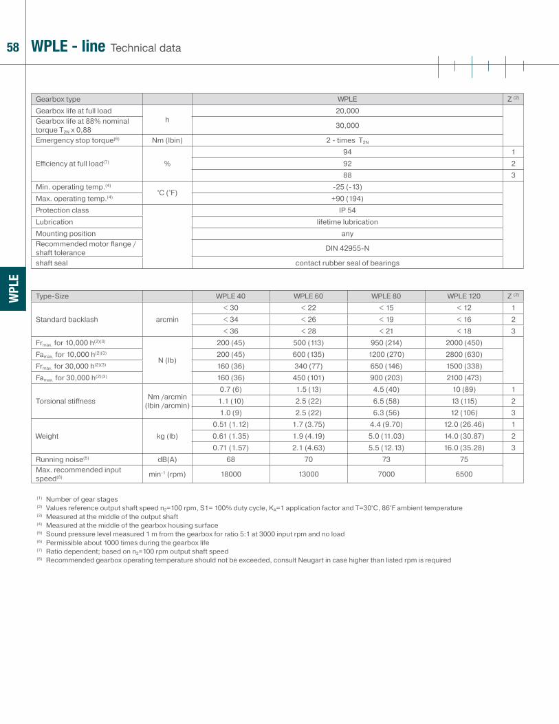
58
WPL
E
(1) Number of gear stages(2) Values reference output shaft speed n2=100 rpm, S1= 100% duty cycle, KA=1 application factor and T=30°C, 86°F ambient temperature(3) Measured at the middle of the output shaft(4) Measured at the middle of the gearbox housing surface(5) Sound pressure level measured 1 m from the gearbox for ratio 5:1 at 3000 input rpm and no load(6) Permissible about 1000 times during the gearbox life(7) Ratio dependent; based on n2=100 rpm output shaft speed(8) Recommended gearbox operating temperature should not be exceeded, consult Neugart in case higher than listed rpm is required
Type-Size WPLE 40 WPLE 60 WPLE 80 WPLE 120 Z (2)
Standard backlash arcmin< 30 < 22 < 15 < 12 1< 34 < 26 < 19 < 16 2< 36 < 28 < 21 < 18 3
Frmax. for 10,000 h(2)(3)
N (lb)
200 (45) 500 (113) 950 (214) 2000 (450)Famax. for 10,000 h(2)(3) 200 (45) 600 (135) 1200 (270) 2800 (630)Frmax. for 30,000 h(2)(3) 160 (36) 340 (77) 650 (146) 1500 (338)Famax. for 30,000 h(2)(3) 160 (36) 450 (101) 900 (203) 2100 (473)
Torsional stiff ness Nm /arcmin (lbin /arcmin)
0.7 (6) 1.5 (13) 4.5 (40) 10 (89) 11.1 (10) 2.5 (22) 6.5 (58) 13 (115) 21.0 (9) 2.5 (22) 6.3 (56) 12 (106) 3
Weight kg (lb)0.51 (1.12) 1.7 (3.75) 4.4 (9.70) 12.0 (26.46) 10.61 (1.35) 1.9 (4.19) 5.0 (11.03) 14.0 (30.87) 20.71 (1.57) 2.1 (4.63) 5.5 (12.13) 16.0 (35.28) 3
Running noise(5) dB(A) 68 70 73 75Max. recommended input speed(8) min-1 (rpm) 18000 13000 7000 6500
Gearbox type WPLE Z (2)
Gearbox life at full load h
20,000Gearbox life at 88% nominal torque T2N x 0,88 30,000
Emergency stop torque(6) Nm (lbin) 2 - times T2N
Effi ciency at full load(7) %94 192 288 3
Min. operating temp.(4)
°C (°F)-25 (-13)
Max. operating temp.(4) +90 (194)Protection class IP 54Lubrication lifetime lubricationMounting position anyRecommended motor fl ange / shaft tolerance DIN 42955-N
shaft seal contact rubber seal of bearings
Technical dataWPLE - line

59
WPL
E
(1) Number of gear stages(2) Values reference output shaft speed n2=100 rpm, S1= 100% duty cycle, KA=1 application factor and T=30°C, 86°F ambient temperature(3) Measured at the middle of the output shaft(4) Measured at the middle of the gearbox housing surface(5) Sound pressure level measured 1 m from the gearbox for ratio 5:1 at 3000 input rpm and no load(6) Permissible about 1000 times during the gearbox life(7) Ratio dependent; based on n2=100 rpm output shaft speed(8) Recommended gearbox operating temperature should not be exceeded, consult Neugart in case higher than listed rpm is required
Type-Size WPLE 80/90 WPLE 120/115 Z (2)
Standard backlash arcmin< 15 < 12 1< 19 < 16 2< 21 < 18 3
Frmax. for 10,000 h(2)(3)
N (lb)
2500 (563) 3500 (788)Famax. for 10,000 h(2)(3) 2800 (630) 2800 (630)Frmax. for 30,000 h(2)(3) 1700 (383) 2400 (540)Famax. for 30,000 h(2)(3) 2000 (450) 2100 (473)
Torsional stiff ness Nm /arcmin (lbin /arcmin)
4.5 (40) 10 (89) 16.5 (58) 13 (115) 26.3 (56) 12 (106) 3
Weight kg (lb)5.5 (12.13) 12.6 (27.78) 16.1 (13.45) 14.6 (32.19) 26.6 (14.55) 16.6 (36.60) 3
Running noise(5) dB(A) 73 75Max. recommended input speed(8) min-1 (rpm) 7000 6500
Gearbox type WPLE Z (2)
Gearbox life at full load h
20,000Gearbox life at 88% nominal torque T2N x 0,88 30,000
Emergency stop torque(6) Nm (lbin) 2 - times T2N
Effi ciency at full load(7) %94 192 288 3
Min. operating temp.(4)
°C (°F)-25 (-13)
Max. operating temp.(4) +90 (194)Protection class IP 54Lubrication lifetime lubricationMounting position anyRecommended motor fl ange / shaft tolerance DIN 42955-N
shaft seal contact rubber seal of bearings
Technical dataWPLE - line

60
WPL
E
(1) Ratio (i=n1 rpm high speed side/n2 rpm low speed side)(2) Recommended gearbox operating temperature should not be exceeded, consult Neugart in case higher than listed rpm is required(3) Exact definition see page 81
Type-Size WPLE 40 WPLE 60 WPLE 80 WPLE 120 i (1)
Recommended max. mean input speed at 50% rated continuous duty torque (S1) rpm(2)(3)
min-1 (rpm)
5000 4500 4000 3500 35000 4500 4000 3500 45000 4500 4000 3500 55000 4500 4000 3500 85000 4500 3600 3450 95000 4500 4000 3500 125000 4500 4000 3500 155000 4500 4000 3500 165000 4500 4000 3500 205000 4500 4000 3500 255000 4500 4000 3500 325000 4500 4000 3500 405000 4500 4000 3500 605000 4500 4000 3500 645000 4500 4000 3500 805000 4500 4000 3500 1005000 4500 4000 3500 1205000 4500 4000 3500 1605000 4500 4000 3500 2005000 4500 4000 3500 2565000 4500 4000 3500 3205000 4500 4000 3500 512
Type-Size WPLE 40 WPLE 60 WPLE 80 WPLE 120 i (1)
Recommended max. mean input speed at 100% rated continuous duty torque (S1) rpm(2)(3)
min-1 (rpm)
5000 4450 2750 2200 35000 4450 2650 2150 45000 4400 2650 2150 55000 4500 4000 3300 83350 3850 2150 2050 95000 4500 2850 2150 125000 4500 3550 2800 155000 4500 3400 2650 165000 4500 4000 3050 205000 4500 4000 3500 255000 4500 4000 3500 325000 4500 4000 3500 405000 4500 4000 3500 605000 4500 4000 3500 645000 4500 4000 3500 805000 4500 4000 3500 1005000 4500 4000 3500 1205000 4500 4000 3500 1605000 4500 4000 3500 2005000 4500 4000 3500 2565000 4500 4000 3500 3205000 4500 4000 3500 512
Technical dataWPLE - line
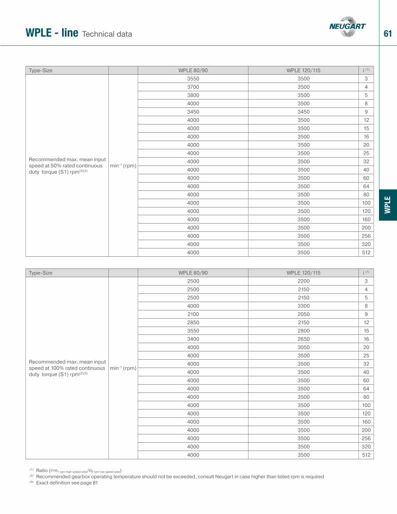
61
WPL
E
(1) Ratio (i=n1 rpm high speed side/n2 rpm low speed side)(2) Recommended gearbox operating temperature should not be exceeded, consult Neugart in case higher than listed rpm is required(3) Exact definition see page 81
Type-Size WPLE 80/90 WPLE 120/115 i (1)
Recommended max. mean input speed at 50% rated continuous duty torque (S1) rpm(2)(3)
min-1 (rpm)
3550 3500 33700 3500 43800 3500 54000 3500 83450 3450 94000 3500 124000 3500 154000 3500 164000 3500 204000 3500 254000 3500 324000 3500 404000 3500 604000 3500 644000 3500 804000 3500 1004000 3500 1204000 3500 1604000 3500 2004000 3500 2564000 3500 3204000 3500 512
Type-Size WPLE 80/90 WPLE 120/115 i (1)
Recommended max. mean input speed at 100% rated continuous duty torque (S1) rpm(2)(3)
min-1 (rpm)
2500 2200 32500 2150 42500 2150 54000 3300 82100 2050 92850 2150 123550 2800 153400 2650 164000 3050 204000 3500 254000 3500 324000 3500 404000 3500 604000 3500 644000 3500 804000 3500 1004000 3500 1204000 3500 1604000 3500 2004000 3500 2564000 3500 3204000 3500 512
Technical dataWPLE - line

62
WPL
E
(1) Ratio (i=n1 rpm high speed side/n2 rpm low speed side)(2) The moment of inertia relates to the high speed side (typically motor shaft)
Type-Size WPLE 40 WPLE 60 WPLE 80 WPLE 120 i (1)
Mass moment of inertia (2) kgcm² (lbin s² x 10-4)
0.044 (0.39) 0.246 (2.18) 1.189 (10.52) 5.75 (50.89) 30.035 (0.31) 0.204 (1.81) 0.939 (8.31) 3.91 (34.60) 40.032 (0.28) 0.189 (1.67) 0.869 (7.69) 3.35 (29.65) 50.030 (0.27) 0.176 (1.56) 0.809 (7.16) 2.89 (25.58) 80.043 (0.38) 0.242 (2.14) 1.159 (10.26) 5.73 (50.71) 90.042 (0.37) 0.238 (2.11) 1.139 (10.08) 5.60 (49.56) 120.036 (0.32) 0.188 (1.66) 1.129 (9.99) 5.53 (48.94) 150.035 (0.31) 0.199 (1.76) 0.919 (8.13) 3.83 (33.90) 160.032 (0.28) 0.186 (1.65) 0.859 (7.60) 3.28 (29.03) 200.032 (0.28) 0.186 (1.65) 0.859 (7.60) 3.26 (28.85) 250.030 (0.27) 0.175 (1.55) 0.809 (7.16) 2.84 (25.13) 320.029 (0.26) 0.175 (1.55) 0.809 (7.16) 2.84 (25.13) 400.042 (0.37) 0.187 (1.65) 0.929 (8.22) 5.62 (49.74) 600.029 (0.26) 0.175 (1.55) 0.809 (7.16) 2.84 (25.13) 640.032 (0.28) 0.186 (1.65) 0.919 (8.13) 3.28 (29.03) 800.032 (0.28) 0.186 (1.65) 0.859 (7.60) 3.26 (28.85) 1000.042 (0.37) 0.175 (1.55) 1.119 (9.90) 5.47 (48.41) 1200.029 (0.26) 0.175 (1.55) 0.809 (7.16) 2.84 (25.13) 1600.029 (0.26) 0.175 (1.55) 0.809 (7.16) 2.84 (25.13) 2000.029 (0.26) 0.175 (1.55) 0.809 (7.16) 2.84 (25.13) 2560.029 (0.26) 0.175 (1.55) 0.809 (7.16) 2.84 (25.13) 3200.029 (0.26) 0.175 (1.55) 0.809 (7.16) 2.84 (25.13) 512
Technical dataWPLE - line

63
WPL
E
(1) Ratio (i=n1 rpm high speed side/n2 rpm low speed side)(2) The moment of inertia relates to the high speed side (typically motor shaft)
Type-Size WPLE 80/90 WPLE 120/115 i (1)
Mass moment of inertia (2) kgcm² (lbin s² x 10-4)
1.189 (10.52) 5.75 (50.89) 30.939 (8.31) 3.91 (34.60) 40.869 (7.69) 3.35 (29.65) 50.809 (7.16) 2.89 (25.58) 8
1.159 (10.26) 5.73 (50.71) 91.139 (10.08) 5.60 (49.56) 121.129 (9.99) 5.53 (48.94) 150.919 (8.13) 3.83 (33.90) 160.859 (7.60) 3.28 (29.03) 200.859 (7.60) 3.26 (28.85) 250.809 (7.16) 2.84 (25.13) 320.809 (7.16) 2.84 (25.13) 400.929 (8.22) 5.62 (49.74) 600.809 (7.16) 2.84 (25.13) 640.919 (8.13) 3.28 (29.03) 800.859 (7.60) 3.26 (28.85) 1001.119 (9.90) 5.47 (48.41) 1200.809 (7.16) 2.84 (25.13) 1600.809 (7.16) 2.84 (25.13) 2000.809 (7.16) 2.84 (25.13) 2560.809 (7.16) 2.84 (25.13) 3200.809 (7.16) 2.84 (25.13) 512
Technical dataWPLE - line
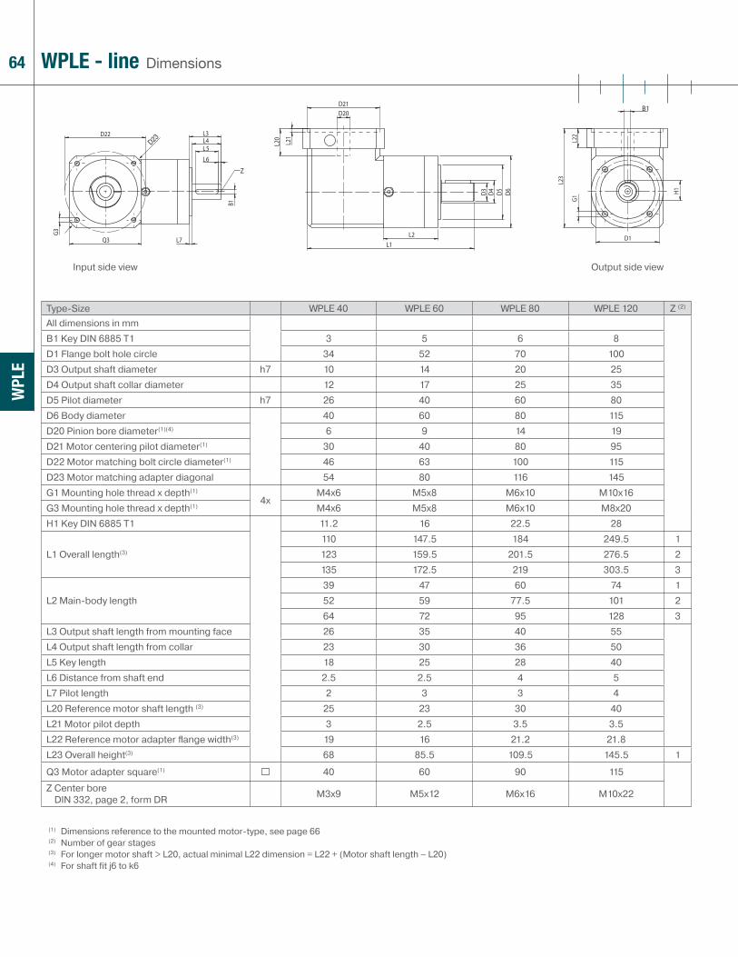
64
WPL
E
Type-Size WPLE 40 WPLE 60 WPLE 80 WPLE 120 Z (2)
All dimensions in mmB1 Key DIN 6885 T1 3 5 6 8D1 Flange bolt hole circle 34 52 70 100D3 Output shaft diameter h7 10 14 20 25D4 Output shaft collar diameter 12 17 25 35D5 Pilot diameter h7 26 40 60 80D6 Body diameter 40 60 80 115D20 Pinion bore diameter(1)(4) 6 9 14 19D21 Motor centering pilot diameter(1) 30 40 80 95D22 Motor matching bolt circle diameter(1) 46 63 100 115D23 Motor matching adapter diagonal 54 80 116 145G1 Mounting hole thread x depth(1)
4xM4x6 M5x8 M6x10 M10x16
G3 Mounting hole thread x depth(1) M4x6 M5x8 M6x10 M8x20H1 Key DIN 6885 T1 11.2 16 22.5 28
L1 Overall length(3)
110 147.5 184 249.5 1123 159.5 201.5 276.5 2135 172.5 219 303.5 3
L2 Main-body length39 47 60 74 152 59 77.5 101 264 72 95 128 3
L3 Output shaft length from mounting face 26 35 40 55L4 Output shaft length from collar 23 30 36 50L5 Key length 18 25 28 40L6 Distance from shaft end 2.5 2.5 4 5L7 Pilot length 2 3 3 4L20 Reference motor shaft length (3) 25 23 30 40L21 Motor pilot depth 3 2.5 3.5 3.5L22 Reference motor adapter fl ange width(3) 19 16 21.2 21.8L23 Overall height(3) 68 85.5 109.5 145.5 1
Q3 Motor adapter square(1) 40 60 90 115
Z Center boreDIN 332, page 2, form DR M3x9 M5x12 M6x16 M10x22
(1) Dimensions reference to the mounted motor-type, see page 66(2) Number of gear stages(3) For longer motor shaft > L20, actual minimal L22 dimension = L22 + (Motor shaft length – L20) (4) For shaft fit j6 to k6
DimensionsWPLE - line
Input side view Output side view
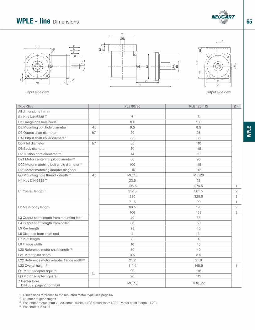
65
WPL
E
Type-Size PLE 80/90 PLE 120/115 Z (2)
All dimensions in mmB1 Key DIN 6885 T1 6 8D1 Flange bolt hole circle 100 130D2 Mounting bolt hole diameter 4x 6.5 8.5D3 Output shaft diameter h7 20 25D4 Output shaft collar diameter 35 35D5 Pilot diameter h7 80 110D6 Body diameter 80 115D20 Pinion bore diameter(1)(4) 14 19D21 Motor centering pilot diameter(1) 80 95D22 Motor matching bolt circle diameter(1) 100 115D23 Motor matching adapter diagonal 116 145G3 Mounting hole thread x depth(1) 4x M6x15 M8x20H1 Key DIN 6885 T1 22.5 28
L1 Overall length(3)
195.5 274.5 1212.5 301.5 2230 328.5 3
L2 Main-body length71.5 99 188.5 126 2106 153 3
L3 Output shaft length from mounting face 40 55L4 Output shaft length from collar 36 50L5 Key length 28 40L6 Distance from shaft end 4 5L7 Pilot length 3 4L8 Flange width 10 15L20 Reference motor shaft length (3) 30 40L21 Motor pilot depth 3.5 3.5L22 Reference motor adapter fl ange width(3) 21.2 21.8L23 Overall height(3) 114.5 145.5 1Q1 Motor adapter square 90 115Q3 Motor adapter square(1) 90 115Z Center bore
DIN 332, page 2, form DR M6x16 M10x22
(1) Dimensions reference to the mounted motor-type, see page 66(2) Number of gear stages(3) For longer motor shaft > L20, actual minimal L22 dimension = L22 + (Motor shaft length – L20) (4) For shaft fit j6 to k6
DimensionsWPLE - line
Input side view Output side view

66
See pagefor other options 77
B5 B14
WPL
E
(1) Other dimensions on inquiry(2) Number of gear stages(3) Provided that flange dimensions are compatible(4) In horizontal and stationary mounting position(5) Shaft fit: j6; k6
Type-Size WPLE 40 WPLE 60 WPLE 80-80/90 WPLE 120-120/115 Z (2)
D4 Motor mounting hole diameter(3) any any any anyD30 Motor shaft diameter/
Available pinion bores / bushings(1)(5) mm 4/5/6/6.35/8/9
6/6.35/8/9/9.525/11/14
9.525/10/11/12/12.7/14/15.875/16/19
11/12.7/14/15.875/16/19/22/24
D31 Motor pilot diameter(3) any any any anyD32 Motor bolt hole diameter(3) any any any anyD33 Hole circle diameter(3) any any any anyG4 Motor mounting thread size any any any anyL30 min. motor shaft length(1) mm 12.5 16 19 21L31 pilot depth any any any anyN Number of bolt holes 4 4 4 4
Q3 Min fl ange square(1) 40 60 42 115
Recommended max. motor weight(4) kg (lb) 2 (4.41) 3.5 (7.72) 9 (19.85) 16 (35.28)Motor type(1) B5/B14 B5/B14 B5/B14 B5/B14Recommended clamping screw tightening torque Nm (lbin) 2 (18) 4.5 (40) 9.5 (84) 16.5 (146)
SW wrench width mm 2.5 3 4 5
OP 2: Motor Mount option Note: B5 mounting depicted;
B14 motor mounting requires special/custom motor adapter
OptionsWPLE - line

67WPLE - line Cross-sectional drawing
1 Output shaftMade of high-strength high quality steel for high shaft reliability
2 Output shaft bearingDeep groove ball bearings with contact seals
3 Planet gearsPrecision zero helix angle gear with optimized profi le modifi cations and crowning; case hardened and hard fi nished by honing
4 Housing with integrated ring gearRing gear is case hardened and precision honed for high loadability, minimum wear, consistent backlash
5 Sun gearPrecision machined optimized gear profi le, case hardened and honed for high loadability, low running noise, minimum wear, and consistent backlash
6 Sun gear bearingPaired deep groove ball bearings
7 Motor matching adapter plateMatches the gear head with virtually any servo motor; made of aluminum for enhanced thermal conductivity
8 Clamping ringBalanced ring, suitable for high rpm, made of steel to allow high clamping forces for safe torque transfer
9 Clamping screwHigh strength steel screw with special low pitch thread to generate a high clamping force
10 PCS SystemPatented multiple closed slot Precision Clamping System - most reliable advanced system available today
11 Assembly boreAccess bore for the clamping screw
12 Bevel gearsStraight tooth bevel gears; hardened
1
23
4
56
7
8
910
11
WPL
E
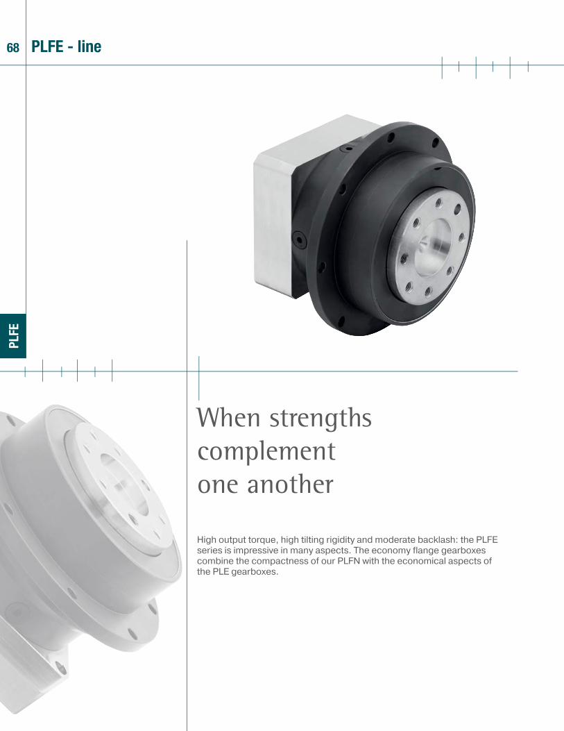
68
PLFE
High output torque, high tilting rigidity and moderate backlash: the PLFE series is impressive in many aspects. The economy flange gearboxes combine the compactness of our PLFN with the economical aspects of the PLE gearboxes.
When strengths complement one another
PLFE - line

69
PLFE
> Low backlash
> High output torque - the industry‘s highest torque density
> Highest tilting stiffness
> Precise, easy, and flexible motor mounting (PCS-2 System)
> Balanced motor pinion
> High efficiency (up to 96%)
> 13 ratios 3:1 to 64:1
> Low noise (< 65 dB(A))
> Consistent quality (ISO 9001 and 14001)
> Output flange according to EN ISO 9409
> Direction of rotation equidirectional
> Operable in any mounting positions
> Lifetime lubrication
> Numerous options
1 Technical data page 70
2 Dimensions page 73
3 Options page 77
4 Possible motor mounting page 74
5 Sectional drawing page 75
6 Ordering code page 76
7 Gearhead sizing/selection page 78
8 Conversion table page 77
9 CAD drawings, dimension sheets www.neugartusa.com
10 Sizing/calculation/selection NCP Software, free download from the Neugart website
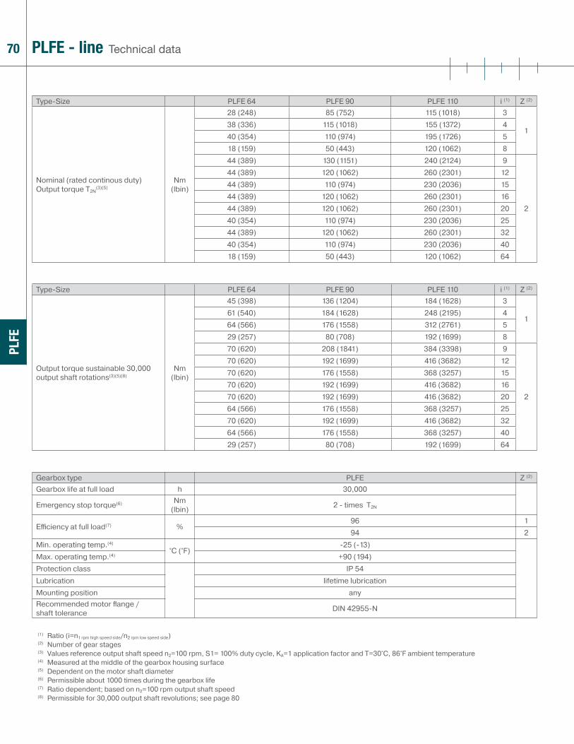
70
PLFE
Technical dataPLFE - line
Type-Size PLFE 64 PLFE 90 PLFE 110 i (1) Z (2)
Nominal (rated continous duty) Output torque T2N
(3)(5)Nm
(lbin)
28 (248) 85 (752) 115 (1018) 3
138 (336) 115 (1018) 155 (1372) 440 (354) 110 (974) 195 (1726) 518 (159) 50 (443) 120 (1062) 844 (389) 130 (1151) 240 (2124) 9
2
44 (389) 120 (1062) 260 (2301) 1244 (389) 110 (974) 230 (2036) 1544 (389) 120 (1062) 260 (2301) 1644 (389) 120 (1062) 260 (2301) 2040 (354) 110 (974) 230 (2036) 2544 (389) 120 (1062) 260 (2301) 3240 (354) 110 (974) 230 (2036) 4018 (159) 50 (443) 120 (1062) 64
Type-Size PLFE 64 PLFE 90 PLFE 110 i (1) Z (2)
Output torque sustainable 30,000 output shaft rotations(3)(5)(8)
Nm (lbin)
45 (398) 136 (1204) 184 (1628) 3
161 (540) 184 (1628) 248 (2195) 464 (566) 176 (1558) 312 (2761) 529 (257) 80 (708) 192 (1699) 870 (620) 208 (1841) 384 (3398) 9
2
70 (620) 192 (1699) 416 (3682) 1270 (620) 176 (1558) 368 (3257) 1570 (620) 192 (1699) 416 (3682) 1670 (620) 192 (1699) 416 (3682) 2064 (566) 176 (1558) 368 (3257) 2570 (620) 192 (1699) 416 (3682) 3264 (566) 176 (1558) 368 (3257) 4029 (257) 80 (708) 192 (1699) 64
Gearbox type PLFE Z (2)
Gearbox life at full load h 30,000
Emergency stop torque(6) Nm (lbin) 2 - times T2N
Effi ciency at full load(7) %96 194 2
Min. operating temp.(4)
°C (°F)-25 (-13)
Max. operating temp.(4) +90 (194)Protection class IP 54Lubrication lifetime lubricationMounting position anyRecommended motor fl ange / shaft tolerance DIN 42955-N
(1) Ratio (i=n1 rpm high speed side/n2 rpm low speed side)(2) Number of gear stages(3) Values reference output shaft speed n2=100 rpm, S1= 100% duty cycle, KA=1 application factor and T=30°C, 86°F ambient temperature(4) Measured at the middle of the gearbox housing surface (5) Dependent on the motor shaft diameter (6) Permissible about 1000 times during the gearbox life(7) Ratio dependent; based on n2=100 rpm output shaft speed(8) Permissible for 30,000 output shaft revolutions; see page 80

71
PLFE
Technical dataPLFE - line
Type-Size PLFE 64 PLFE 90 PLFE 110 Z (2)
Standard backlash arcmin< 16 < 9 < 8 1< 20 < 14 < 12 2
Frmax. for 20,000 h(3)(4)
N (lb)
550 (124) 1400 (315) 2400 (540)Famax. for 20,000 h(3)(4) 1200 (270) 3000 (675) 3300 (743)Frmax. for 30,000 h(3)(4) 500 (113) 1200 (270) 2100 (473)Famax. for 30,000 h(3)(4) 1200 (270) 3000 (675) 3300 (743)
Torsional stiff ness Nm /arcmin (lbin /arcmin)
18 (159) 34 (301) 93 (823) 112 (106) 25 (221) 68 (602) 2
Weight kg (lb)1.1 (2.43) 2.9 (6.39) 7.0 (15.44) 11.5 (3.31) 3.3 (7.28) 9.0 (19.85) 2
Running noise(5) dB(A) 58 60 65Max. recommended input speed(6) min-1 (rpm) 13000 7000 6500
Type-Size PLFE 64 PLFE 90 PLFE 110 i (1)
Recommended max. mean input speed at 50% rated continuous duty torque (S1) rpm(6)(7)
min-1 (rpm)
3600 2750 2450 34450 2800 2550 44500 3400 2650 54500 4000 3500 84500 4000 3200 94500 4000 3300 124500 4000 3500 154500 4000 3500 164500 4000 3500 204500 4000 3500 254500 4000 3500 324500 4000 3500 404500 4000 3500 64
Type-Size PLFE 64 PLFE 90 PLFE 110 i (1)
Recommended max. mean input speed at 100% rated continuous duty torque (S1) rpm(6)(7)
min-1 (rpm)
3000 1900 1700 33200 1800 1700 43650 2250 1700 54500 4000 3250 84150 2500 2000 94500 3200 2000 124500 4000 2650 154500 3800 2450 164500 4000 2900 204500 4000 3500 254500 4000 3500 324500 4000 3500 404500 4000 3500 64
(1) Ratio (i=n1 rpm high speed side/n2 rpm low speed side)(2) Number of gear stages(3) Values reference output shaft speed n2=100 rpm, S1= 100% duty cycle, KA=1 application factor and T=30°C, 86°F ambient temperature(4) Reference to the rotating output flange face (5) Sound pressure level measured 1 m from the gearbox for ratio 5:1 at 3000 input rpm and no load(6) Recommended gearbox operating temperature should not be exceeded, consult Neugart in case higher than listed rpm is required(7) Exact definition see page 81
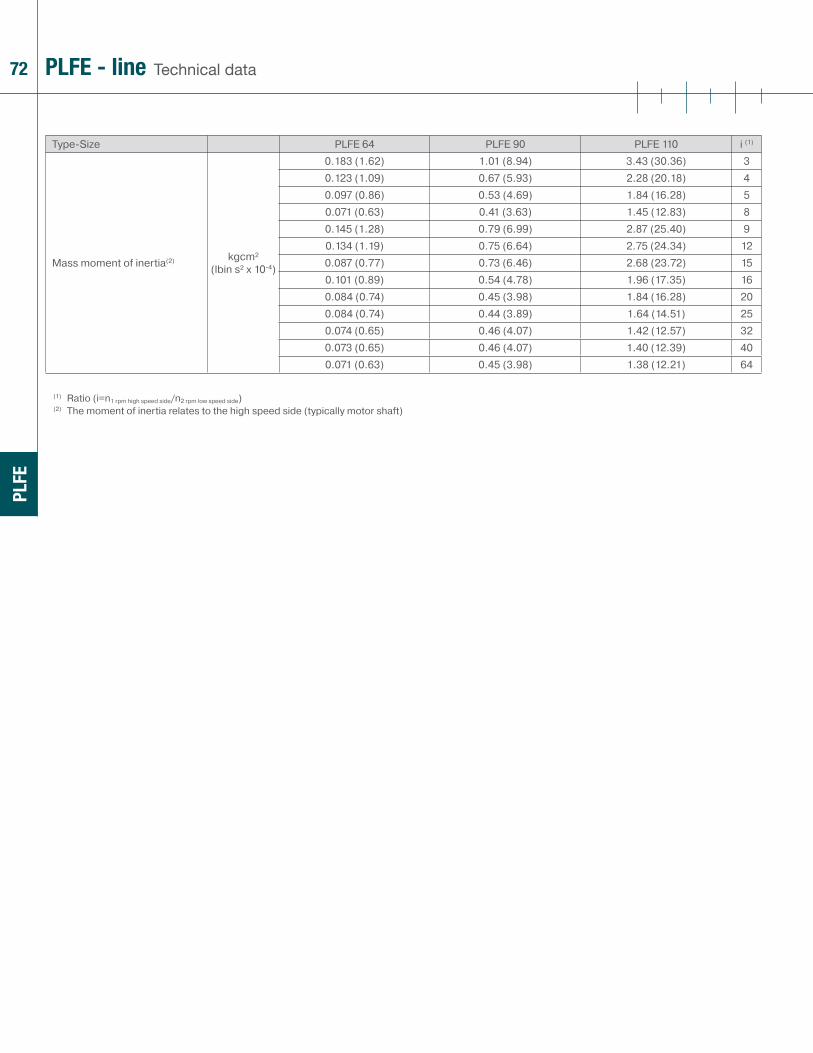
72
PLFE
Technical dataPLFE - line
Type-Size PLFE 64 PLFE 90 PLFE 110 i (1)
Mass moment of inertia(2) kgcm² (lbin s² x 10-4)
0.183 (1.62) 1.01 (8.94) 3.43 (30.36) 30.123 (1.09) 0.67 (5.93) 2.28 (20.18) 40.097 (0.86) 0.53 (4.69) 1.84 (16.28) 50.071 (0.63) 0.41 (3.63) 1.45 (12.83) 80.145 (1.28) 0.79 (6.99) 2.87 (25.40) 90.134 (1.19) 0.75 (6.64) 2.75 (24.34) 120.087 (0.77) 0.73 (6.46) 2.68 (23.72) 150.101 (0.89) 0.54 (4.78) 1.96 (17.35) 160.084 (0.74) 0.45 (3.98) 1.84 (16.28) 200.084 (0.74) 0.44 (3.89) 1.64 (14.51) 250.074 (0.65) 0.46 (4.07) 1.42 (12.57) 320.073 (0.65) 0.46 (4.07) 1.40 (12.39) 400.071 (0.63) 0.45 (3.98) 1.38 (12.21) 64
(1) Ratio (i=n1 rpm high speed side/n2 rpm low speed side)(2) The moment of inertia relates to the high speed side (typically motor shaft)
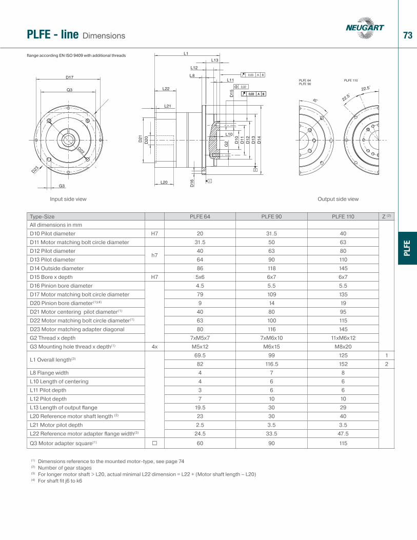
73
PLFE
EE
E
flange according EN ISO 9409 with additional threads
DimensionsPLFE - line
Type-Size PLFE 64 PLFE 90 PLFE 110 Z (2)
All dimensions in mmD10 Pilot diameter H7 20 31.5 40D11 Motor matching bolt circle diameter 31.5 50 63D12 Pilot diameter
h740 63 80
D13 Pilot diameter 64 90 110D14 Outside diameter 86 118 145D15 Bore x depth H7 5x6 6x7 6x7D16 Pinion bore diameter 4.5 5.5 5.5D17 Motor matching bolt circle diameter 79 109 135D20 Pinion bore diameter(1)(4) 9 14 19D21 Motor centering pilot diameter(1) 40 80 95D22 Motor matching bolt circle diameter(1) 63 100 115D23 Motor matching adapter diagonal 80 116 145G2 Thread x depth 7xM5x7 7xM6x10 11xM6x12G3 Mounting hole thread x depth(1) 4x M5x12 M6x15 M8x20
L1 Overall length(3)69.5 99 125 182 116.5 152 2
L8 Flange width 4 7 8L10 Length of centering 4 6 6L11 Pilot depth 3 6 6L12 Pilot depth 7 10 10L13 Length of output fl ange 19.5 30 29L20 Reference motor shaft length (3) 23 30 40L21 Motor pilot depth 2.5 3.5 3.5L22 Reference motor adapter fl ange width(3) 24.5 33.5 47.5
Q3 Motor adapter square(1) 60 90 115
(1) Dimensions reference to the mounted motor-type, see page 74(2) Number of gear stages(3) For longer motor shaft > L20, actual minimal L22 dimension = L22 + (Motor shaft length – L20)(4) For shaft fit j6 to k6
Input side view Output side view

74
PLFE
B5
B14
OP 2: Motor Mount option Note: B5 mounting depicted;
B14 motor mounting requires special/custom motor adapter
OptionsPLFE - line
Type-Size PLFE 64 PLFE 90 PLFE 110 Z (2)
D4 Motor mounting hole diameter(3) any any any
D30 Motor shaft diameter/Available pinion bores / bushings(1)(5) mm 6/6.35/8/9/9.525/
11/14/15.875 16/199.525/10/11/12/12.7/
14/15.875 16/19/22/2411/12.7/14/15.875/16/19/
22/24/28/32/35
D31 Motor pilot diameter(3) any any anyD32 Motor bolt hole diameter(3) any any anyD33 Hole circle diameter(3) any any anyD34 Output fl ange diagonal(1) mm 80 116 145G4 Motor mounting thread size any any anyL30 Min. motor shaft length(1) mm 16 (19(6)) 19 (21(7)) 21 (26(8))L31 pilot depth any any anyN Number of bolt holes 4 4 4
Q3 Flange square(1) 60 90 115
Recommended max. motor weight(4) kg (lb) 3.5 (7.72) 9 (19.85) 16.5 (36.38)Motor type(1) B5/B14 B5/B14 B5/B14
Recommended clamping screw tightening torque
Nm (lbin)
4.5(40)
9.5(84)
9.5(84)
16.5(146)
16.5(146)
40(354)
SW wrench width mm 3 4 4 5 5 6
(1) Other dimensions on inquiry(2) Number of gear stages(3) Provided that flange dimensions are compatible(4) In horizontal and stationary mounting position(5) Shaft fit: j6; k6(6) D30 >14 mm(7) D30 >19 mm(8) D30 >24 mm
See pagefor other options 77

75
1 Output fl ange shaftHigh strength one piece planet carrier & output shaft
2 Output shaft bearingLarge deep groove ball bearings with contact seals
3 Planet gearsPrecision zero helix angle gear with optimized profi le modifi cations and crowning; case hardened and hard fi nished by honing
4 Housing with integrated ring gearRing gear is case hardened and precision honed for high loadability, minimum wear, consistent backlash
5 Sun gearPrecision machined optimized gear profi le, case hardened and honed for high loadability, low running noise, minimum wear, and consistent backlash
6 Sun gear bearingHigh speed ball bearings in fl oating arrangement, eliminating thrust loads from thermal expansion, and yet providing exact positioning for easy mounting
7 Motor matching adapter plateMatches the gear head with virtually any servo motor; made of aluminum for enhanced thermal conductivity
8 Clamping ringBalanced ring, suitable for high rpm, made of steel to allow high clamping forces for safe torque transfer
9 Clamping screwHigh strength steel screw with special low pitch thread to generate a high clamping force
10 PCS SystemPatented multiple closed slot Precision Clamping System - most reliable advanced system available today
11 Assembly boreAccess bore for the clamping screw
PLFE - line Cross-sectional drawing
12
3
4
5
6
7
8
9
10
11
PLFE

76
Gearbox type Type-Size ratio i motor designation Options pagePLN
PLN 70 3 – 100 (Manufacturer-Model) OP 2 12PLN 90 OP 5 13PLN 115 OP 7 13PLN 142 OP 8 13PLN 190 OP 14 14
OP 16 77OP 17 77OP 18 77
WPLNWPLN 70 4 – 100 (Manufacturer-Model) OP 2 24WPLN 90 OP 5 25WPLN 115 OP 7 25WPLN 142 OP 8 25
OP 14 26OP 16 77OP 17 77
PLFNPLFN 64 4 – 100 (Manufacturer-Model) OP 2 36PLFN 90 OP 16 77PLFN 110 OP 17 77PLFN 140 OP 18 77
PLEPLE 40 3 – 512 (Manufacturer-Model) OP 1 50PLE 60; PLE 60/70 OP 2 52PLE 80, PLE 80/90 OP 6 77PLE 120, PLE 120/115 OP 12 77PLE 160 OP 16 77
OP 17 77WPLE
WPLE 40 3 – 512 (Manufacturer-Model) OP 2 66WPLE 60 OP 6 77WPLE 80, WPLE 80/90 OP 12 77WPLE 120, WPLE 120/115 OP 16 77
OP 17 77PLFE
PLFE 64 3 – 64 (Manufacturer-Model) OP 2 74PLFE 90 OP 12 77PLFE 110 OP 16 77
OP 17 77
Ordering code
Orde
ring
code
PLN 70 – 3 / Motor – OP 5 + 14

77Options
OP 1: Solid input shaft (1)
OP 2: Motor mounting
OP 5: Splined shaft (1)
OP 6: Smooth output shaftSmooth shaft without key/keyway or threaded bore in shaft end
OP 7 : Output shaft with key DIN 6885 T1 (1)
OP 8: Special / custom shaft (1)
OP 12: ATEX (1)
qualifi ed after ATEX 94/9 EG for group IIcategory 2G/3Gtemperature class: T4 XRating data could be updated, Please request separate data sheet!
OP 14: Output flange and shaft similar to the (W)PLS output
OP 16: Food-grade lubricationspecial lubrication for application with special hygienic regulations
OP 17: Low temperature lubricationspecial lubrication for application at extremely low temperatures; observe special conditions
OP 18: Reduced backlash
Other options on inquiry(1) on inquiry
Conversion table 1 mm 0.0394 in
1 N 0.225 lbf
1 kg 2.205 lb
1 Nm 8.85 in lb
1 kgcm2 8.85 x 10⁻⁴ in lb s2
Optio
ns

78
A
C
B
Gearhead sizing/selection
1) required gearhead torque rating
detailed application data available?(acceleration- deceleration- torque, load and
- motor inertias, speeds, cycle times, etc.)
some basic application data available?(motor peak torque, load and motor inertia or
inertia match ratio )
selection only based on motor torque(peak-torque, continuous duty torque)
I: required gearhead torque rating
TRGRT = TMAT (max. application torque)
II: required gearhead torque rating
TRGRT = [(TMpeak-TLR) * (1-k)+TLR] * i
A: selected gearhead could be oversized
TRGRT = TMpeak * i
B: selected gearhead could be undersized
TRGRT = TMcont * i
C: gearhead selection adequate, slight probability of gearhead under-sizing
TRGRT = TMcont * 2,5 * i
select gearhead size based on the criteria:
TRGRT T2N (2)
(1) it is recommended to compile data and use selection
method I or II(2)
short cycle times and low cycle rates application the gearhead can be perhaps selected based on TRGRT < 1,6 * T2N. Contact Neugart for assistance.
2) check motor / selected gearhead geometrical compatibility - motor shaft diameter <= max possible input pinion (sun-gear) bore? - motor weight permissible / support required?
3) check output shaft radial and axial loadability / output shaft bearing life (if applicable)
4) check application / ambient conditions -If In doubt please contact Neugart for assistance - Is the IP class adequate? - Is the mean input speed higher than recommended? - Check if the operating temperature is higher than recommended?
no
no
yes
yes
TRGRT - required gearhead torque rating
TMAT - peak application torque
TMpeak - peak motor torque
TMcont - continuous duty motor torque
T2N - gearhead rated torque
i - ratio
TL - friction load (non-dynamic load)
TLR - TLR = TL / i load torque at the input
JM - motor inertia
JL - load inertia
JLR - JLR = JL / i2 reflected load inertia to the input
k - k = JM / (JLR + JM) inertia parameter
IMR - IMR = JLR / JM inertia match ratio; is closely related to inertia parameter (k = 1 / (IMR+1)
Gear
head
siz
ing/
sele
ctio
n

79for your notes
additional information www.neugartusa.com
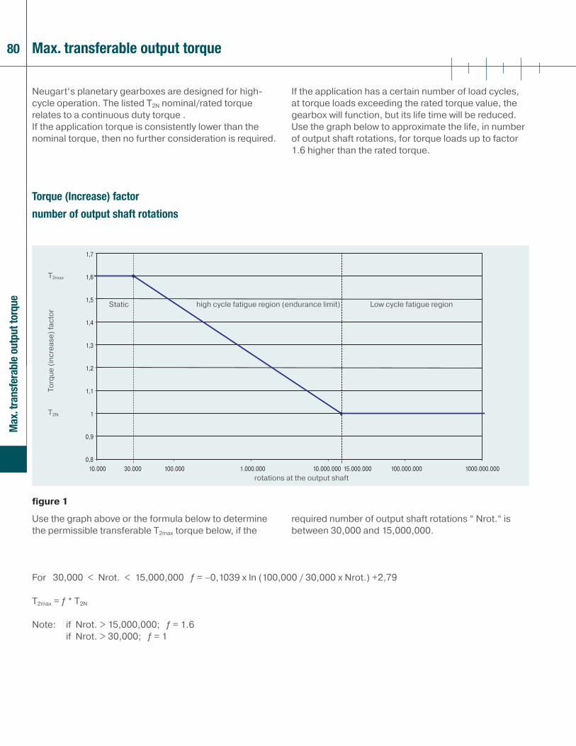
80
T2max
T2N
10.000 30.000 100.000 1.000.000 10.000.000 15.000.000 100.000.000 1000.000.000
1,7
1,6
1,5
1,4
1,3
1,2
1,1
1
0,9
0,8
Max
. tra
nsfe
rabl
e ou
tput
torq
ue
Max. transferable output torque
Torque (Increase) factor
number of output shaft rotations
Neugart‘s planetary gearboxes are designed for high-cycle operation. The listed T2N nominal/rated torque relates to a continuous duty torque .If the application torque is consistently lower than the nominal torque, then no further consideration is required.
If the application has a certain number of load cycles, at torque loads exceeding the rated torque value, the gearbox will function, but its life time will be reduced. Use the graph below to approximate the life, in number of output shaft rotations, for torque loads up to factor 1.6 higher than the rated torque.
Use the graph above or the formula below to determine the permissible transferable T2max torque below, if the
required number of output shaft rotations “ Nrot.“ is between 30,000 and 15,000,000.
Torq
ue (i
ncre
ase)
fact
or
rotations at the output shaft
Static high cycle fatigue region (endurance limit) Low cycle fatigue region
For 30,000 < Nrot. < 15,000,000 � = –0,1039 x ln (100,000 / 30,000 x Nrot.) +2,79
T2max = � * T2N
Note: if Nrot. > 15,000,000; � = 1.6 if Nrot. > 30,000; � = 1
figure 1
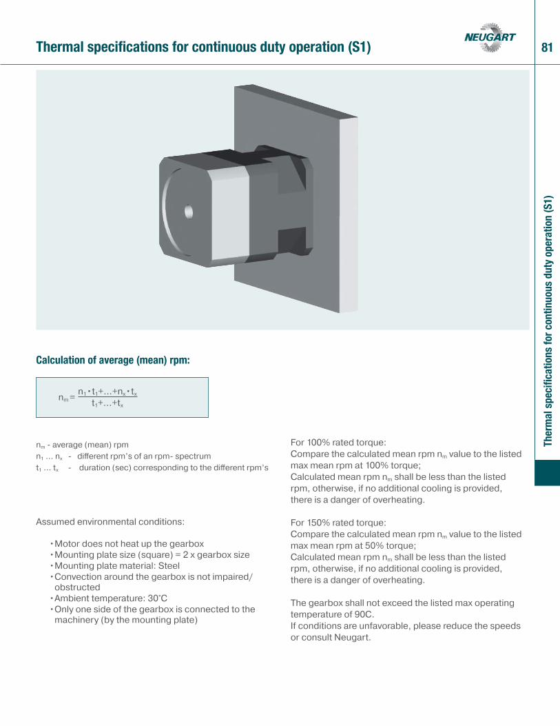
81
Ther
mal
spe
cific
atio
ns fo
r con
tinuo
us d
uty
oper
atio
n (S
1)
Thermal specifications for continuous duty operation (S1)
Calculation of average (mean) rpm:
Assumed environmental conditions:
• Motor does not heat up the gearbox• Mounting plate size (square) = 2 x gearbox size• Mounting plate material: Steel• Convection around the gearbox is not impaired/
obstructed • Ambient temperature: 30°C• Only one side of the gearbox is connected to the
machinery (by the mounting plate)
For 100% rated torque: Compare the calculated mean rpm nm value to the listed max mean rpm at 100% torque;Calculated mean rpm nm shall be less than the listed rpm, otherwise, if no additional cooling is provided, there is a danger of overheating.
For 150% rated torque: Compare the calculated mean rpm nm value to the listed max mean rpm at 50% torque; Calculated mean rpm nm shall be less than the listed rpm, otherwise, if no additional cooling is provided, there is a danger of overheating.
The gearbox shall not exceed the listed max operating temperature of 90C.If conditions are unfavorable, please reduce the speeds or consult Neugart.
nm = n1•t1+...+nx•tx
t1+...+tx
nm - average (mean) rpm n1 … nx - diff erent rpm’s of an rpm- spectrum t1 … tx - duration (sec) corresponding to the diff erent rpm’s
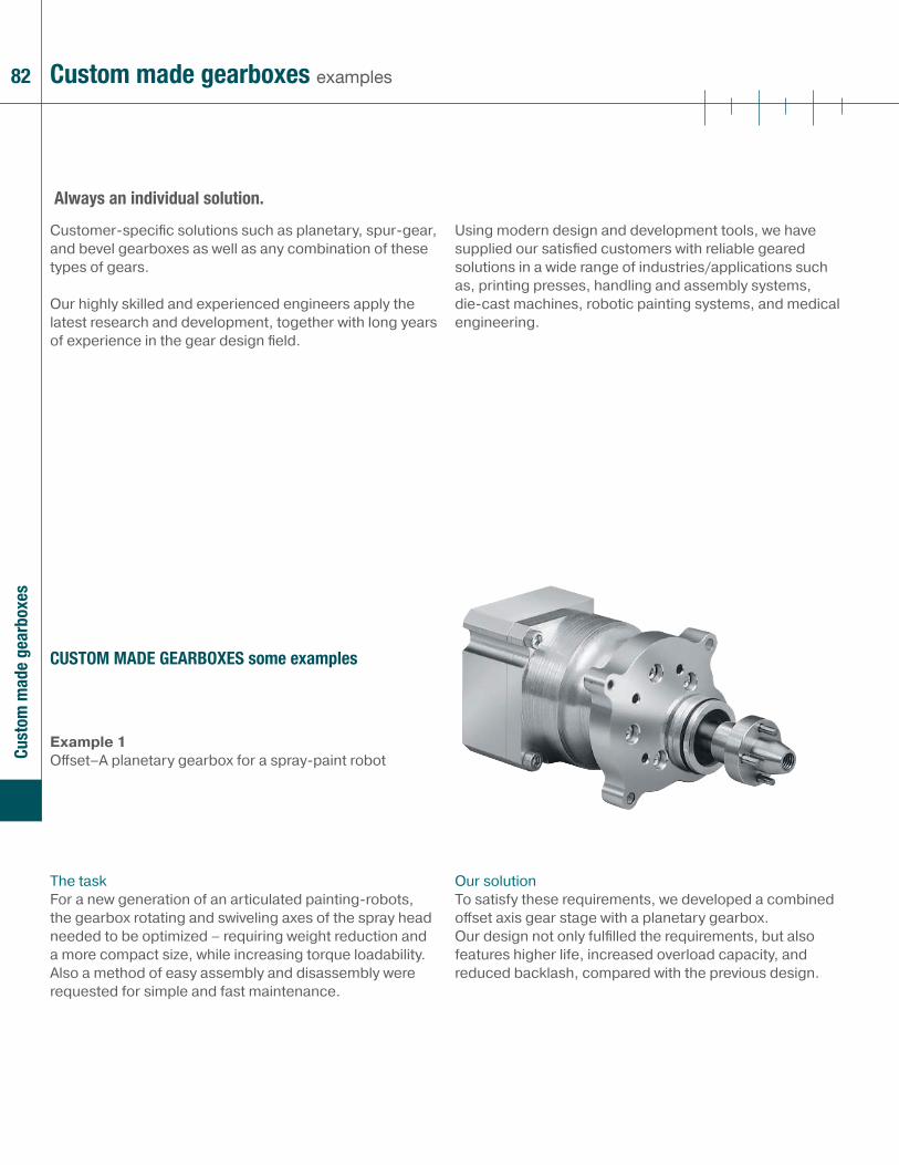
82 Custom made gearboxes examples
Customer-specifi c solutions such as planetary, spur-gear, and bevel gearboxes as well as any combination of these types of gears.
Our highly skilled and experienced engineers apply the latest research and development, together with long years of experience in the gear design fi eld.
Using modern design and development tools, we have supplied our satisfi ed customers with reliable geared solutions in a wide range of industries/applications such as, printing presses, handling and assembly systems, die-cast machines, robotic painting systems, and medical engineering.
Always an individual solution.
Example 1Off set–A planetary gearbox for a spray-paint robot
The taskFor a new generation of an articulated painting-robots, the gearbox rotating and swiveling axes of the spray head needed to be optimized – requiring weight reduction and a more compact size, while increasing torque loadability. Also a method of easy assembly and disassembly were requested for simple and fast maintenance.
Our solutionTo satisfy these requirements, we developed a combined off set axis gear stage with a planetary gearbox. Our design not only fulfi lled the requirements, but also features higher life, increased overload capacity, and reduced backlash, compared with the previous design.
CUSTOM MADE GEARBOXES some examples
Cust
om m
ade
gear
boxe
s
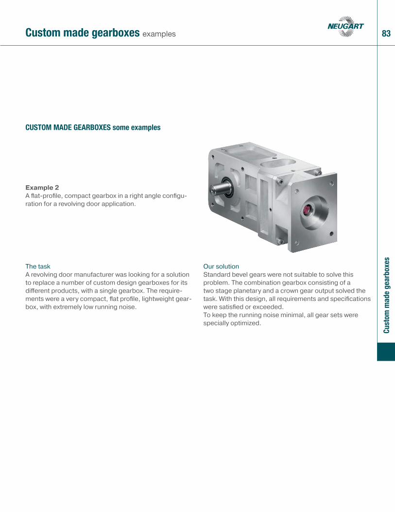
83Custom made gearboxes examples
Cust
om m
ade
gear
boxe
s
Example 2A fl at-profi le, compact gearbox in a right angle confi gu-ration for a revolving door application.
The taskA revolving door manufacturer was looking for a solution to replace a number of custom design gearboxes for its diff erent products, with a single gearbox. The require-ments were a very compact, fl at profi le, lightweight gear-box, with extremely low running noise.
Our solutionStandard bevel gears were not suitable to solve this problem. The combination gearbox consisting of a two stage planetary and a crown gear output solved the task. With this design, all requirements and specifi cations were satisfi ed or exceeded. To keep the running noise minimal, all gear sets were specially optimized.
CUSTOM MADE GEARBOXES some examples
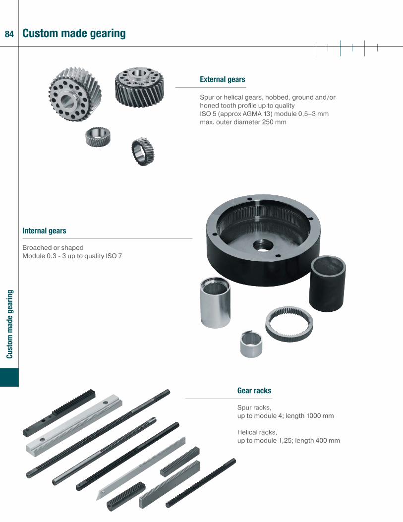
84 Custom made gearing
Gear racks
Spur racks,up to module 4; length 1000 mm
Helical racks, up to module 1,25; length 400 mm
External gears
Spur or helical gears, hobbed, ground and/or honed tooth profi le up to quality ISO 5 (approx AGMA 13) module 0,5–3 mm max. outer diameter 250 mm
Cust
om m
ade
gear
ing
Internal gears
Broached or shapedModule 0.3 - 3 up to quality ISO 7
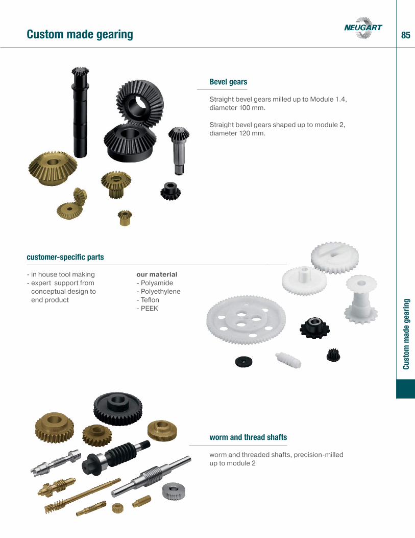
85Custom made gearing
worm and thread shafts
worm and threaded shafts, precision-milled up to module 2
customer-specific parts
- in house tool making- expert support from
conceptual design to end product
our material- Polyamide- Polyethylene- Tefl on- PEEK
Cust
om m
ade
gear
ing
Bevel gears
Straight bevel gears milled up to Module 1.4, diameter 100 mm.
Straight bevel gears shaped up to module 2, diameter 120 mm.
86
Pennsylvania – Machining, stocking, assembly, and sales engineering supportNeugart USA LP 3047 Industrial Bethel Park , PA 15102 USA phone: (+1) 412 835-4154 fax: (+1) 412 835-4194email: [email protected]: www.neugartusa.com
Virginia –Stocking, assembly, sales, engineering supportNeugart USA LP 508 Central Drive Suite 107Virginia Beach, VA 23454 USAphone: (+1) 757 577-2741 fax: (+1) 757 962-0369 email: [email protected]: www.neugartusa.com
World Headquarters – Design, manufacturing, assembly Neugart GmbH Keltenstraße 16 D-77971 Kippenheim phone: (+49) 7825-847 0 fax: (+49) 7825-847 2999email: [email protected]: www.neugart.de
Contact national
Cont
act

87
Belgium Caldic Techniek Belgium NV SA Tollaan 73 Avenue du Péage B-1932 Sint Stevens Woluwe phone: (+32) 2720/49 81 fax: (+32) 2720/81 01email: [email protected]: www.caldic.com
NetherlandsELECTRO ABI b.v. Aandrijf-en besturingstechniek A. Hofmanweg 60 NL-2031 BL Haarlem phone: (+31) 23/5319292 fax: (+31) 23/5326599email: [email protected]: www.abi.nl
SwedenSDT Scandinavian Drive Technologies Sabelgatan 4 S-25467 Helsingborg phone: (+46) 42/380800 fax: (+46) 42/380813email: [email protected]: www.sdt.se
DenmarkServoTech A/S Ulvehavevej 42-46DK-7100 Vejle phone: (+45) 7942/80 80 fax: (+45) 7942/80 81 email: [email protected]: www.servotech.dk
NetherlandsCaldic Techniek b.v. Schuttevaerweg 60 NL-3044BB-Rotterdam phone: (+31) 104/156622 fax: (+31) 104/378810email: [email protected]: www.caldic.com
Czech RepublicTAT pohonova technika spol.s.r.o.Hranicni 53CZ-370 06 Ceske Budejovicephone: +420 (387) 414 414fax: +420 (387) 414 415email: [email protected]: www.tat.at
FranceAtlanta Neugart France S.A.R.L.Europarc Tecparc 40, Rue Eugène DUPUISF-94000 Créteilphone:(+33) 1567 11760 fax: (+33) 1567 11764email: [email protected]: www.atlanta-neugart.com
ItalyNeugart Italia S.r.l.Strada Carignano 30 bisI-10024 Moncalieri - TO phone: (+39) 011/6408248 fax: (+39) 011/6406205 email: [email protected]: www.neugartitalia.it
SwitzerlandRelex AG Antriebstechnik Schachenstrasse 80 CH-8645 Jona SG phone: (+41) 55-225 46 11 fax: (+41) 55-225 46 19 email: [email protected]: www.relex.ch
Great BritainHMK Technical Services Ltd. Kappa House, Hatter Street Congleton GB-Cheshire CW 12 1 Q1 phone: (+44) 1260/279411 fax: (+44) 1260/281022email: [email protected]: www.hmkdirect.com
AustriaTAT Technom Antriebstechnik GesmbHHaidbachstr. 1 A-4061 Pasching phone: (+43) 7229/64840-0 fax: (+43) 7229/61817email: [email protected]: www.tat.at
SpainBrotomatic, S.L.Poligono de Ali-GobeoC/San Miguel de Acha, 2-Pab3 01010 Vitoria-GasteizAlava phone: (+34) 945/249411/249776fax: (+34) 945-227832 email: [email protected]: www.brotomatic.es
GreeceKYMA GmbH Meseon54629 Thessalonikiphone: (+302) 310 556 239fax: (+302) 310 534 302email: [email protected]: www.kyma.gr
PolandP.P.H. Wobit Witold Ober PL 61-474 Poznan ul. Gruszkowa 4 phone: (+48) 61/291 2225 fax: (+48) 61/291 0764 email: [email protected] internet: www.wobit.com.pl
Contact international
Cont
act
88 Contact international
BrazilNeugart do Brasil LtdaAv. Antonio Carlos Cômitre, 1393/1651 sala 27Parque Campolim – 18047-620Sorocaba – SPinternet: www.neugart.com.br
KoreaIntech Automation Inc. 1-1108, Ace Hitech City 55-20 Mullae-Dong 3-GaYoungdeungpo-Ku, Seoul, Korea 150-834phone: (+82) 2/2439-0070-4 fax: (+82) 2/2439-0080 email: [email protected]: www.intechautomation.co.kr
TurkeyNeugart TurkiyeBahcelievler mah. Gazi paşa cad. Gülnihal Palmiye ap.75/1 KAt 1 daire 1Yalova /Türkiyephone:(+90) 226 813 15 40fax: (+90) 226 813 15 42email: [email protected]: www.neugart.com.tr
ChinaNeugart Planetary Gearboxes (Shenyang) Co., Ltd.E&T Developm. Zone, LiaoningE&T Development Zone, shenyang No.Eight street,10 jia 2 haoRC 110141Shenyang PR Chinaphone: (+86) 24/25195797/ 25374959/25378129fax: (+86) 24/25372552email: [email protected]: www.neugart.net.cn
MalaysiaAims Motion Technology Son Bhd.No. 19, Jalan Industri PBP 8,Taman Industri Pusat Bandar Puchong,47100 Puchong, Selangor,Malaysia.phone: (+6) 03-5882 1896fax: (+6) 03-5882 1845email: [email protected]: www.aimsmotion.com.my
USA / CanadaNeugart USA, LP 3047 Industrial Blvd. Bethel Park, PA 15102-2537, USA phone: (+1) 412/8354154 fax: (+1) 412/8354194 email: [email protected]: www.neugartusa.com
IndiaFluro Engineerung PVT. Ltd.Plot No.B-29/1MIDC,TalojaDist: Raigad (Navi Mumbai)-410208Indiaphone: (+91)-22-2741-9999, 2741-1922, 2740-1455fax: (+91)-22-2741-1933email: [email protected]: www.fluroengg.com
SingaporePower Transmission GermanySingaporean-German Chamber ofIndustry and Commerce (SGC)25 International Business Park#03-105 German CentreSingapore 609916phone: (+65)-6562 8500fax: (+65)-6562 8510internet: www.neugart.de
IsraelSUZIN TRANSMISSION SYSTEM LTD.Motion control & transmission technology56 Halozie Hatasia St.P.O.B 10316Haifa Bay 26111, Israelphone:(+972) 4/8724148, 8725708fax: (+972) 4/8414284email: [email protected]: www.suzin.co.il
TaiwanAlteks Co., Ltd.5F, 580, Sec. 1, Min-Sheng N. Road,Kuei-Shan Hsiang,Taoyuan Hsien,phone: 886-3-2121020fax: 886-3-2121250email: [email protected]: www.alteks.com.tw
Cont
act

additional information www.neugartusa.com
Neugart USA, LP - PA Facility 3047 Industrial Blvd. Bethel Park, PA 15102-2537, USAPhone: 1-412-835-4154Fax: 1-412-835-4194
Neugart USA, LP - VA Facility 508 Central Drive, Suite 107Virginia Beach VA, 23454, USAPhone: 1-757-418-2530 Fax: 1-757-962-0369
email: [email protected]: www.neugartusa.com
Power. Precision. Partnership
precision gearboxes
11/2
009
· mod
ifi ca
tions
res
erve
d