
Netzwerk-Außenkamera Outdoor Network Camera · Video signal (PAL) zur Verfügung, wenn die...
20
ELECTRONICS FOR SPECIALISTS ELECTRONICS FOR SPECIALISTS ELECTRONICS FOR SPECIALISTS ELECTRONICS FOR SPECIALISTS BEDIENUNGSANLEITUNG INSTRUCTION MANUAL MODE D’EMPLOI ISTRUZIONI PER L’USO Netzwerk-Außenkamera Outdoor Network Camera INC-2622 BV Bestellnummer • Order Number 18.4710
Transcript of Netzwerk-Außenkamera Outdoor Network Camera · Video signal (PAL) zur Verfügung, wenn die...

ELECTRONICS FOR SPECIALISTS ELECTRONICS FOR SPECIALISTS ELECTRONICS FOR SPECIALISTS ELECTRONICS FOR SPECIALISTS
BEDIENUNGSANLEITUNG
INSTRUCTION MANUAL
MODE D’EMPLOI
ISTRUZIONI PER L’USO
Netzwerk-Außenkamera
Outdoor Network Camera
INC-2622 BVBestellnummer • Order Number 18.4710

2
12V
LAN
Audio Input
Audio Output
AlarmIN0COM0OUT1COM1
26
1
3
8
9
10
11
12
13
7
4 5
76
15
14
16 1917 18
“TOP” “TOP”
15
18
➀
➁ ➂
Alarm
IN 0 gelb yellow jaune giallo
COM 0 orange orange orange arancio
OUT 1 grau grey gris grigio
COM 1 violett purple violet violetto

ELECTRONICS FOR SPECIALISTS ELECTRONICS FOR SPECIALISTS ELECTRONICS FOR SPECIALISTS ELECTRONICS FOR SPECIALISTS
3
Deutsch . . . . . . . . . . .Seite 4
English . . . . . . . . . . . .Page 8
Français . . . . . . . . . . .Page 12
Italiano . . . . . . . . . . . .Pagina 16

4
Deu
tsch
DeutschDeutsch Seite
Netzwerk-AußenkameraDiese Anleitung richtet sich an Installateu-re von Video überwachungsanlagen . Bitte lesen Sie die Anleitung vor der Installation gründlich durch und heben Sie sie für ein späteres Nachlesen auf .
1 VerwendungsmöglichkeitenDie Kamera INC-2622BV ist speziell für den Einsatz in Video-Überwachungsan-lagen auf der Basis von Computer-Netz-werken konzipiert . Durch ihr wetterfestes Ge häuse (Schutzart IP 66) ist sie auch für die Außeninstallation geeignet . Sie ist mit einem 2-Megapixel-Bild sensor und einem Objektiv variabler Brennweite (6 – 22 mm) ausgestattet und bietet u . a . Bildspiege-lung, Maskierung von Bildbereichen und Bewegungs erkennung . Bei Dunkel heit leuchten die eingebauten Infrarot-LEDs den Überwachungsbereich bis 40 m aus und die Kamera schaltet auf Schwarzweißbe-trieb um . Die Kamera verfügt über einen eingebauten Webserver mit 2-fach-Video-streaming . Für die korrekte Einrichtung sind unbedingt Netzwerktechnik-Kennt nisse er-forderlich .
Die Kamera kann in Verbindung mit einem Netzwerk-Videorekorder (z . B . INR-…*) genutzt werden oder eigenstän-dig über einen Webbrowser . Sie verfügt über einen Audio eingang und einen Audio-ausgang, sodass eine gegenseitige Kom-munikation über einen Computer möglich ist . Ein Schaltausgang erlaubt das Schalten von Geräten, z . B . durch die integrierte Be-wegungserkennung ausgelöst . Zusätzlich verfügt die Kamera über einen Alarmein-gang, über den z . B . eine Aufzeichnung oder eine E-Mail-Benachrichtigung gestar-tet werden kann . Ein Steckplatz für eine Speicherkarte erlaubt die Videoaufzeich-nung in der Kamera, nach Zeitplan oder durch die integrierte Bewegungserkennung ausgelöst . * Tipp: Ist das Kameramodell in der Liste des ver-
wendeten Rekorders nicht vorhanden, das ONVIF-Protokoll wählen .
2 Wichtige HinweiseDie Kamera entspricht allen relevanten Richtlinien der EU und ist deshalb mit gekennzeichnet .
VORSICHT Bei Dunkelheit schalten sich die IR-LEDs ein . Blicken Sie beim Einrichten der Kamera nicht aus der Nähe direkt in die eingeschalteten IR-LEDs . Das Infrarot-licht kann zu einer Reizung der Augen füh-ren . Die IR-Strahlung liegt allerdings weit unterhalb des Emissionsgrenzwertes und ist risikofrei eingestuft nach EN 62471 .
• Schützen Sie die Kamera vor extremen Temperaturen (zulässige Einsatztempe-ratur −30 °C bis +50 °C) .
• Verwenden Sie für die Reinigung keine aggressiven Reinigungsmittel oder Che-mikalien .
• Wird die Kamera zweckentfremdet, nicht richtig angeschlossen, falsch bedient oder nicht fachgerecht repariert, kann keine Haftung für daraus resultierende Sach- oder Personenschäden und keine Garantie für die Kamera übernommen werden . Ebenso kann keine Haftung für durch Fehlbedienung oder durch einen Defekt entstandene Datenverluste und deren Folgeschäden übernommen wer-den .
Soll die Kamera endgültig aus dem Betrieb genommen werden, über-geben Sie sie zur umweltgerechten Entsorgung einem ört lichen Recy-clingbetrieb .
3 Montage1) Um die optimale Montagestelle festzu-
stellen, sollte ein Probebetrieb erfolgen . Dazu die Kamera vorläufig in Betrieb nehmen (☞ folgende Kapitel) .
2) An der Montagestelle (z . B . Wand oder Decke) vier Löcher für die Befestigung der Montageplatte und ggf . ein Loch für das An schluss kabel bohren (das Kabel kann alternativ durch die Aussparung seitlich am Sockel herausgeführt wer-den) . Eine Bohrschablone liegt bei . Bei Bedarf die beiliegenden Dübel (19) ver-wenden .
3) Mit den vier langen Kreuzschlitzschrau-ben (16) die Montageplatte (18) an der Montagestelle befestigen . Bei der Wandmontage darauf achten, dass die Seite mit der Beschriftung „TOP“ nach oben zeigt (☞ Abb . 2) .
4) Die Gummidichtung (17) mit etwas Deh-nung über den Rand der Montageplatte (18) stülpen .
5) Die Schlitzschraube (15) bis zum An-schlag in das Gewinde am Kamera-haltersockel (7) drehen .
6) Den Sockel (7) so auf die Montageplatte (18) setzen, dass der Schraubenkopf in
die Öffnung in der Montageplatte fasst und sich nach einer Linksdrehung darin verriegelt (☞ Abb . 3) .
7) Mit den vier Inbusschrauben (14) den Sockel (7) an der Montageplatte (18) festschrauben .
8) Zum Ausrichten der Kamera die drei Feststellschrauben (6) lösen, die Kamera ausrichten und die Schrauben wieder festdrehen .Vorsicht: Vermeiden Sie die direkte Ausrichtung
der Kamera auf starke Lichtquellen (z . B . Sonne) . Dies könnte die Lebens-dauer des Bildsensors verkürzen .
9) Um das Objektiv vor direkter Sonnenein-strahlung zu schützen, das Sonnendach (1) auf der Kamera positionieren und mit der Feststellschraube (2) fixieren .
4 Kamera anschließenDie Anschlüsse (9 – 13) und der Kabelver-teiler (8) sind nicht wetterfest . Sie müssen entsprechend geschützt werden .
1) Die Kamera über die RJ45-Kupplung (9) mit einem einzelnen Computer, einem lokalen Computernetzwerk oder, z . B . über einen Router, mit größeren Compu-ternetzwerken (Internet) verbinden . Die beiliegende Schutzhülse kann über den Stecker des Anschlusskabels geschoben und mit der Kupplung verriegelt werden .
Auf der Kameraunterseite ist durch das Fenster im Deckel des Fachs eine gelbe LED (22 in Abb . 4) sichtbar . Diese blinkt beim Bestehen einer Netzwerk-verbindung .Hinweis: Bei einer direkten Verbindung mit
einem Computer wird ggf . ein Cros-sover-Kabel benötigt .
2) Für die Tonübertragung über das Netz-werk kann an die Cinch-Kupplung „Audio Input“ (11) eine Tonquelle mit Line-Pegel (z . B . Mikrofon mit Vorverstär-ker) angeschlossen werden .
3) Für die Tonwiedergabe an die Cinch-Kupplung „Audio Output“ (12) einen Kopfhörerverstärker oder eine Lautsprecher anlage anschließen .
4) Zur Auswertung eines Alarmgebers die Anschlüsse (13) IN 0 und COM 0 über einen Schließkontakt oder Öffner (in den Kameraeinstellungen wählbar) ver-binden .
5) Zum Schalten eines Gerätes, z . B . über ein Relais, den Schaltausgang der Ka-mera über die Anschlüsse (13) OUT 1 und COM 1 anschließen . Die Schalt-charakteristik (Öffner/ Schließer, Puls) ist in den Kameraeinstellungen wählbar . Der Ausgang ist max . mit ⎓12 V/ 300 mA belastbar .
6) Soll die Kamera eigenständig Video-Auf-zeichnungen durchführen, nach Lösen der Schraube (5) den Deckel des Fachs

5
Deu
tschöffnen und eine Speicherkarte vom Typ
„SD[HC]“ (max . 32 GB) einsetzen . Den Schreibschutz der Karte (seitlicher
Schieber) deaktivieren . Die Karte mit den Kontakten zur Kamera vorderseite zei-gend in den Schlitz (20) schieben, bis sie einrastet . Die rote LED (21) leuchtet bei eingesetzter Karte . Ein Adapter für Karten vom Typ „micro SD[HC]“ liegt bei .
Die Karte zum Entnehmen etwas hinein drücken, sodass sie ausrastet . Eine laufende Aufnahme unbedingt zuvor beenden!
➃
2321
22
24
20
Den Deckel wieder dicht verschließen .
7) An die Kupplung (10) ein stabilisiertes 12-V-Netz gerät mit einer Dauerbelast-barkeit von 400 mA (z . B . 1210DC oder PS-120WP) über einen Hohlstecker ⌀ 5,5 / 2,1 mm (außen /innen) anschlie-ßen . Dabei die Polung beachten: Mittelkontakt = + .
Alternativ lässt sich die Kamera auch über das Netzwerkkabel versorgen (Power over Ethernet IEEE 802 .3af) .
5 Brennweite und Fokus einstellen
Durch Drehen der Schrauben an der Un-terseite können die Brennweite [Zoom (4)] und die Schärfe [Focus (3)] eingestellt wer-den . Als Hilfe für die Einstellungen steht im Fach an der Kameraunterseite ein analoges Video signal (PAL) zur Verfügung, wenn die
Signalausgabe (CVBS) in den Kameraein-stellungen aktiviert wurde (☞ Kapitel 7) . Den Deckel des Fachs durch Lösen der Schraube (5) öffnen und die Cinch- Buchse (24 in Abb . 4) mit dem Eingang eines Monitors verbinden .
Nach der Durchführung der Einstellungen den Deckel wieder dicht verschließen .
6 Kamera in ein Netzwerk einbinden
Damit die Kamera zum Konfigurieren über einen Computer direkt angesprochen wer-den kann, ist ihre IP-Adresse vom Werk aus auf 192 .168 .0 .120 voreingestellt .
Ist die aktuelle Adresse der Kamera nicht bekannt, zum Finden der Kamera im Netz-werk das auf der beiliegenden CD enthalte-ne Programm „IPSearch .exe“ starten .
1) Um die Suche zu starten, auf der Regis-terkarte „Multicast Search“ die Schalt-fläche „Start“ anklicken . Die im Netz-werk gefundenen Kameras werden in der Liste auf der linken Seite angezeigt (☞ Abb . 5) .
2) Zum Beenden der Suche auf die Schalt-fläche „Stop“ klicken .
3) Die Kamera in der Liste auswählen . Auf der rechten Seite werden jetzt die aktuellen Einstellungen dieser Kamera gezeigt .
4) Die Einstellungen nach Bedarf ändern: IP-Adresse, Teilnetzmaske und Gate-way-Adresse können statisch festgelegt werden (Option „Device uses the follo-wing IP address“ wählen) . Dabei muss für jede Kamera eine eindeutige IP-Ad-resse eingegeben werden . Existiert in dem Netzwerk ein DHCP-Server (z . B . im Router oder Netzwerk-Videorekorder),
kann dieser Einstellungen für die Kame-ra automatisch vornehmen (Option „De-vice obtains an IP address automatically“ wählen); die automatisch vergebenen Werte sind dann grau hinterlegt und können nicht geändert werden .
5) Auf die Schaltfläche „Modify“ klicken . Bei erfolgreicher Übertragung der Än-derungen wird die Meldung „Modify success!“ angezeigt .
6) Vor einer erneuten Suche kann die Liste über die Schaltfläche „Clear All“ gelöscht werden
➄

6
Deu
tsch 7 Kamera über einen
Computer aufrufenDie Bedienoberfläche der Kamera kann durch die Eingabe ihrer IP-Adresse in der Adresszeile des Programms Windows In-ternet Explorer (IE, Version 6 oder höher) aufgerufen werden . Dazu müssen die IP-Adressen vom Computer und der Ka-mera demselben Teilnetz angehören . Es sind max . 6 gleichzeitige Zu griffe auf die Kamera möglich .
Beim Aufruf der Kamera erscheint zu-nächst das Anmeldefenster . Hier die Spra-che für die Benutzeroberfläche wählen; die folgende Beschreibung bezieht sich auf die Einstellung „Deutsch“ . Anschließend den Benutzernamen und das Passwort ein- geben (Vorgabe für beide Eingaben: admin) . In den Kameraeinstellungen kön-nen später eigene Anmeldedaten fest- gelegt werden .Wichtig: Gegen einen unbefugten Zu gang sollte
zumindest das Passwort geändert werden .
Eine einfache Darstellung des Kamerabilds ist mit der auf vielen Computern vorhan-denen Flash-Player-Erweiterung von Adobe möglich (auch auf beiliegender CD) . Für eine schnellere Bildübertragung sowie die Nutzbarkeit aller Funktionen ist jedoch die Installation der ActiveX-Erweiterungen er-forderlich . Diese werden beim erstmaligen Klicken auf die Flash /Ac tiveX-Umschaltzeile g (☞ Abb . 6) aus der Kamera geladen . Wenn nötig, müssen dafür die Sicherheits-einstellungen des IE so gelockert werden, dass dieser Vorgang zugelassen wird . Die
➅
f
e a
g
h
b c d
Installationsdatei „webPlugins .exe“ auf dem Computer speichern, den IE schließen und die Datei ausführen .
Ist die Verbindung zur Kamera aufgebaut, wird die in Abb . 6 gezeigte Ansicht mit dem aktuellen Kamerabild angezeigt, mit folgenden Bedienmöglichkeiten:
a Ansicht „Livebild“ mit Anzeige des Kamerabilds
b Ansicht „Wiedergabe“ zum Abspielen der Aufnahmen aus der Kamera
c Ansicht „Konfiguration“ zum Ändern der Kameraeinstellungen
d Schaltfläche zum Ändern des Passworts
e Schaltfläche zum Abmelden
f Kamerabild mit Informationen zum aktuell übertragenen Stream
g Zum Umschalten zwischen Flash-Player- und AciveX-Nutzung für die Darstellung des Live-Bildes auf diese Zeile klicken .
h Funktionsleiste mit folgenden Funktionen
/ : Beenden / Starten der Bildübertragung
„Stream“: Auswahl eines Streams (zur Änderung die Übertragung eines laufenden Streams mit beenden)
: Tonübertragung von der Kamera ein-/ausschalten [Audio Input (11)]
: Tonübertragung zu der Kamera ein-/ausschalten [Audio Output (12)]
: spezifische Kameraeinstellungen (z . B . Helligkeitsregelung, Spiegelung)
: Schnappschuss-Funktion zum Speichern einer Mo mentaufnahme als Bild
Das Klicken mit rechter Maustaste auf das Kamerabild zeigt folgendes Menü:Menüpunkt Funktion
Vollbild (schließen)Vollbildansicht (beenden) alternativ: Doppelklick auf das Bild
Sensor-Einstellungen speichern wie
Zoom In / OutHinein-/Herauszoomenalternativ: mit Mausrad zoomen oder über dem gewünschten Bild-ausschnitt einen Rahmen aufziehen
Panorama beenden gesamtes Bild zeigen (nach Zoom In)

7
Deu
tsch9 Technische Daten
Bildabtaster: . . . . . . . . . . CMOS, 8,76 mm (10⁄29 ”)
Objektiv: . . . . . . . . . . . . . 1 : 1,4 / 6 – 22 mm, mit geregelter Blende
Blickwinkel: . . . . . . . . . . . 11,4° – 46,5°
Mindestbeleuchtung: . . . 0,01 lx (Farbe), 0,03 lx (S/ W)
Auflösung: . . . . . . . . . . . max . 30 Bilder / s bei 1920 × 1080 Bildpunkten
Elektronischer Verschluss: 1⁄5 – 1/20 000 s
Protokolle: . . . . . . . . . . . IPv4, IPv6, HTTPS, RTSP, DDNS, SMTP, SSL, ONVIF 2 .4 u . a .
Kompressionsverfahren: . MPEG-4 H .264, MJPEG
Videostreaming: . . . . . . . Mainstream 500 – 12 000 kbit /s Substream 100 – 6000 kbit /s
Audio-Bitrate: . . . . . . . . . 64 kbit /s
Netzwerk: . . . . . . . . . . . . Ethernet 10 / 100 Mbit / s
Einsatztemperatur: . . . . . −30 °C bis +50 °C
Schutzart: . . . . . . . . . . . . IP 66
Stromversorgung: . . . . . . ⎓12 V/400 mA oder PoE IEEE 802 .3af
Abmessungen: . . . . . . . . ⌀ 110 mm × 377 mm
Gewicht: . . . . . . . . . . . . . 2,5 kg
Änderungen vorbehalten .
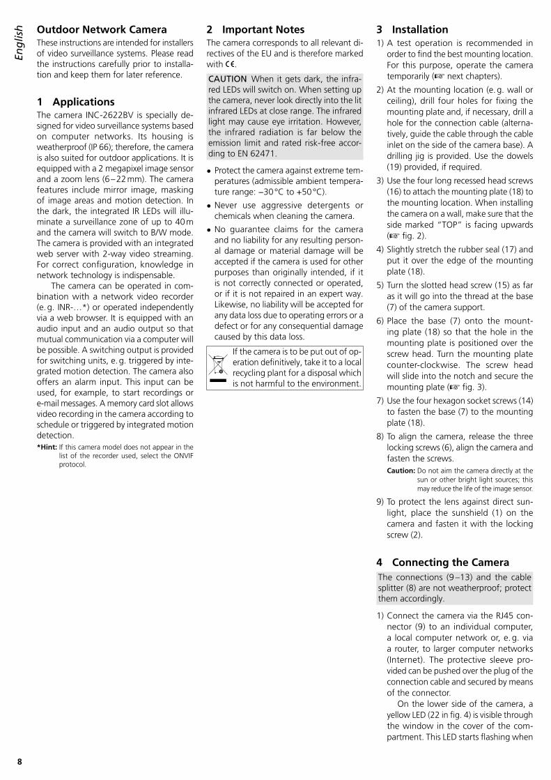
Zum Ändern der Einstellungen für die Ka-mera, über den Reiter c auf die Ansicht „Konfiguration“ umschalten (☞ Abb . 7) . Am linken Rand (i) die gewünschte Rub-rik für die Einstellungen auswählen . Durch Klicken auf ⊞ lassen sich weitere Unterru-briken anzeigen . So lässt sich z . B . unter „Gerät Datum und Zeit“ die aktuelle Zeit für die Kamera einstellen .
Nach dem Ändern einer Einstellung zum Speichern der Änderung auf den grünen Haken ✔ oder die Schaltfläche „übernehmen“ klicken . Zum Laden der aktuellen Einstellungen aus der Kamera auf die Schaltfläche „Aktualisierung“ klicken .Windows ist ein registriertes Warenzeichen der Microsoft Corpo-ration in den USA und anderen Ländern.
8 Rücksetzen der KameraDie Kamera kann auf ihre Werkseinstellun-gen zurückgesetzt werden . Dabei gehen alle vom Anwender durchgeführten Ände-rungen der Kameraeinstellungen verloren .
1) Die Schraube (5) des Deckels lösen und das Fach öffnen .
2) Den Reset-Taster (23) länger als 5 Sekun-den drücken (☞ Abb . 4 in Kapitel 4) . Der Rücksetzprozess startet nach dem Loslassen der Taste verzögert und kann einige Minuten dauern .
3) Den Deckel wieder dicht verschließen .
Die Kamera ist jetzt wieder auf die statische IP-Adresse 192 .168 .0 .120 eingestellt, der Benutzername und das Kennwort für die Anmeldung lauten: admin
i
➆Diese Bedienungsanleitung ist urheberrechtlich für MONACOR ® INTERNATIONAL GmbH & Co. KG geschützt. Eine Reproduktion für eigene kommerzielle Zwecke – auch auszugsweise – ist untersagt.
8
English
EnglishEnglish Page
Outdoor Network CameraThese instructions are intended for installers of video surveillance systems . Please read the instructions carefully prior to installa-tion and keep them for later reference .
1 ApplicationsThe camera INC-2622BV is specially de-signed for video surveillance systems based on computer networks . Its housing is weatherproof (IP 66); therefore, the camera is also suited for outdoor applications . It is equipped with a 2 megapixel image sensor and a zoom lens (6 – 22 mm) . The camera features include mirror image, masking of image areas and motion detection . In the dark, the integrated IR LEDs will illu-minate a surveillance zone of up to 40 m and the camera will switch to B/ W mode . The camera is provided with an integrated web server with 2-way video streaming . For correct configuration, knowledge in network technology is indispensable .
The camera can be operated in com-bination with a network video recorder (e . g . INR-…*) or operated independently via a web browser . It is equipped with an audio input and an audio output so that mutual communication via a computer will be possible . A switching output is provided for switching units, e . g . triggered by inte-grated motion detection . The camera also offers an alarm input . This input can be used, for example, to start recordings or e-mail messages . A memory card slot allows video recording in the camera according to schedule or triggered by integrated motion detection .*Hint: If this camera model does not appear in the
list of the recorder used, select the ONVIF protocol .
2 Important NotesThe camera corresponds to all relevant di-rectives of the EU and is therefore marked with .
CAUTION When it gets dark, the infra-red LEDs will switch on . When setting up the camera, never look directly into the lit infrared LEDs at close range . The infrared light may cause eye irritation . However, the infrared radiation is far below the emission limit and rated risk-free accor-ding to EN 62471 .
• Protect the camera against extreme tem-peratures (admissible ambient tempera-ture range: −30 °C to +50 °C) .
• Never use aggressive detergents or chemicals when cleaning the camera .
• No guarantee claims for the camera and no liability for any resulting person-al damage or material damage will be accepted if the camera is used for other purposes than originally intended, if it is not correctly connected or operated, or if it is not repaired in an expert way . Likewise, no liability will be accepted for any data loss due to operating errors or a defect or for any consequential damage caused by this data loss .
If the camera is to be put out of op-eration definitively, take it to a local recycling plant for a disposal which is not harmful to the environment .
3 Installation1) A test operation is recommended in
order to find the best mounting location . For this purpose, operate the camera temporarily (☞ next chapters) .
2) At the mounting location (e . g . wall or ceiling), drill four holes for fixing the mounting plate and, if necessary, drill a hole for the connection cable (alterna-tively, guide the cable through the cable inlet on the side of the camera base) . A drilling jig is provided . Use the dowels (19) provided, if required .
3) Use the four long recessed head screws (16) to attach the mounting plate (18) to the mounting location . When installing the camera on a wall, make sure that the side marked “TOP” is facing upwards (☞ fig . 2) .
4) Slightly stretch the rubber seal (17) and put it over the edge of the mounting plate (18) .
5) Turn the slotted head screw (15) as far as it will go into the thread at the base (7) of the camera support .
6) Place the base (7) onto the mount-ing plate (18) so that the hole in the mounting plate is positioned over the screw head . Turn the mounting plate counter-clockwise . The screw head will slide into the notch and secure the mounting plate (☞ fig . 3) .
7) Use the four hexagon socket screws (14) to fasten the base (7) to the mounting plate (18) .
8) To align the camera, release the three locking screws (6), align the camera and fasten the screws .Caution: Do not aim the camera directly at the
sun or other bright light sources; this may reduce the life of the image sensor .
9) To protect the lens against direct sun-light, place the sunshield (1) on the camera and fasten it with the locking screw (2) .
4 Connecting the CameraThe connections (9 –13) and the cable splitter (8) are not weatherproof; protect them accordingly .
1) Connect the camera via the RJ45 con-nector (9) to an individual computer, a local computer network or, e . g . via a router, to larger computer networks (Internet) . The protective sleeve pro- vided can be pushed over the plug of the connection cable and secured by means of the connector .
On the lower side of the camera, a yellow LED (22 in fig . 4) is visible through the window in the cover of the com-partment . This LED starts flashing when

9
Englishthe camera has been connected to the
network .Note: For direct connection to a computer, a
crossover cable may be required .
2) For audio transmission via the network, connect an audio source with line level (e . g . microphone with preamplifier) to the RCA connector “Audio Input” (11) .
3) For audio reproduction, connect a head-phone amplifier or a sound system to the RCA connector “Audio Output” (12) .
4) To evaluate an alarm device, connect the pins (13) IN 0 and COM 0 via a normally open contact or normally closed contact (to be selected in the camera settings) .
5) To switch a unit (e . g . via a relay), con-nect the switching output of the cam-era via the pins (13) OUT 1 and COM 1 . Select the switching characteristic (nor-mally open contact / normally closed contact, pulse) in the camera settings . The maximum load of the output is ⎓12 V/ 300 mA .
6) For independent video recordings of the camera, release the screw (5), open the cover of the compartment and insert a memory card of the type “SD[HC]” (32 GB max .) .
Disable the write protection of the card (lateral slider) . Push the card (con-tacts to the front of the camera) into the slot (20) until it engages . The red LED (21) will light up when a card is in-serted . An adapter for cards of the type “microSD[HC]” is provided .
To remove the card, push the card into the slot until it disengages . Never remove the card while a recording is being made!
➃
2321
22
24
20
Tightly close the cover again .
7) Connect a regulated 12 V power supply unit with a permanent rating of 400 mA (e . g . PSS-1210DC or PS-120WP) via a DC power connector ⌀ 5 .5 / 2 .1 mm (outside / inside) to the connector (10) . Always observe the correct polarity: centre contact = +
Alternatively, use the network cable (Power over Ethernet IEEE 802 .3af) to supply the camera with power .
5 Adjusting the focal length and the focus
Turn the screws on the lower side to ad-just the focal length [Zoom (4)] and the sharpness [Focus (3)] . To make this easier, an analog video signal (PAL) will be availa-ble in the compartment on the lower side of the camera if the signal output (CVBS) has been activated in the camera settings (☞ chapter 7) . Release the screw (5) to open the compartment and connect the RCA jack (24 in fig . 4) to the input of a monitor .
After making the settings, tightly close the cover again .
6 Connecting the Camera to a Network
To be able to directly address the camera for configuration, its IP address is factory-set to 192 .168 .0 .120 .
If you do not know the current ad-dress of the camera, start the program “IPSearch .exe” from the CD provided to find the camera in the network .
1) To start the search, click the button “Start” of the tab “Multicast Search” . The list on the left will show the cameras found in the network (☞ fig . 5) .
2) To stop the search, click the button “Stop” .
3) Select the camera from the list . The cur-rent settings of this camera can be found on the right .
4) Change the settings as required: IP address, subnet mask and gateway address can be defined as static values (select the option “Device uses the following IP address”) . Enter a unique IP address for each camera . If a DHCP server is available in the network (e . g . in the router or network video recorder), this server will be able to automatically make settings for the camera (select the option “Device obtains an IP address automatically”) . The values assigned automatically are highlighted in grey and cannot be changed .
5) Click the button “Modify” . After suc-cessful transmission of the modifica-tions, the message “Modify success!” will appear .
6) Before you start a new search, click the button “Clear All” to delete the list .
➄

10
English 7 Calling up the Camera via a
ComputerTo call up the user interface of the camera, enter its IP address in the address bar of the program Windows Internet Explorer (IE, version 6 or higher) . The IP addresses of the computer and of the camera must be in the same subnet . The number of simultaneous accesses to the camera is limited to 6 .
When the camera is called up, the log-in window will appear . Select the lan-guage for the user interface . The descrip-tion below refers to English . Then enter the user name and the password (default setting for both: admin) . Individual log-in data can be defined later in the camera settings .Important: To prevent unauthorized access, change
at least the password .
The Flash Player extension from Adobe provided on many computers (also availa-ble on the CD provided) will allow a basic display of the camera image . Faster image transmission and availability of all func-tions, however, requires installation of the ActiveX extensions . These extensions will be loaded from the camera when the Flash /ActiveX line g (☞ fig . 6) is clicked for the first time . If necessary, reduce the security settings of the IE accordingly to allow the installation process . Save the installation file “webPlugins .exe” to the computer, close the IE and execute the file .
➅
f
e a
g
h
b c d
When the connection to the camera has been established, the view with the current camera image (fig . 6) will be displayed . The following options are available:
a View “Live Video” with display of camera image
b View “Playback” to replay the recordings from the camera
c View “Configuration” to change the camera settings
d Button to change the password
e Button to log out
f Camera image with information on the stream currently transmitted
g Click this line to switch between use of Flash Player and ActiveX for display of the live image
h Toolbar with the following functions:
/ : Stop/Start of image transmission
“Stream”: Selection of a stream (when selecting a different stream, click to stop the transmission of the current stream)
: Activation/Deactivation of audio transmission from the camera [Audio Input (11)]
: Activation/Deactivation of audio transmission to the camera [Audio Output (12)]
: Specific camera settings (e . g . brightness control, mirror image)
: Snapshot function to save a snapshot as an image file
When the camera image is clicked with the right mouse button, the following menu will appear:
Menu Item Function
Full Screen (Exit Full Screen)full-screen image (exit) alternatively: double-click the image
Sensor like
Zoom In / Outzooming in / zooming outalternatively: use the scroll wheel to zoom in/out or drag the mouse to select the desired image section
Restore Panorama display of the entire image (after zooming in)
11
English9 Specifications
Image sensor: . . . . . . . . . CMOS, 8 .76 mm (10⁄29 ”)
Lens: . . . . . . . . . . . . . . . . 1 : 1 .4/6 – 22 mm, with DC-controlled iris
Viewing angle: . . . . . . . . 11 .4° – 46 .5°
Minimum illumination: . . 0 .01 lx (colour), 0 .03 lx (B/ W)
Resolution: . . . . . . . . . . . 30 frames max . per second with 1920 × 1080 pixels
Electronic shutter: . . . . . . 1⁄5 – 1/20 000 s
Protocols: . . . . . . . . . . . . IPv4, IPv6, HTTPS, RTSP, DDNS, SMTP, SSL, ONVIF 2 .4 etc .
Compression: . . . . . . . . . MPEG-4 H .264, MJPEG
Video streaming: . . . . . . . Mainstream 500 – 12 000 kbit /s Substream 100 – 6000 kbit /s
Audio bit rate: . . . . . . . . 64 kbit/s
Network: . . . . . . . . . . . . Ethernet 10 /100 Mbit /s
Ambient temperature: . . −30 °C to +50 °C
IP rating: . . . . . . . . . . . . . IP 66
Power supply: . . . . . . . . . ⎓12 V/400 mA or PoE IEEE 802 .3af
Dimensions: . . . . . . . . . . ⌀ 110 mm × 377 mm
Weight: . . . . . . . . . . . . . 2 .5 kg
Subject to technical modification .
To change the settings for the camera, select the tab c and go to the view “Con-figuration” (☞ fig . 7) . On the left (i), select the desired category for the settings . To show additional subcategories, click ⊞ . To set, for example, the current time for the camera, go to “Device Date and Time” .
To save a setting that has been changed, click the green check mark ✔ or the button “Apply” . To load the current settings from the camera, click the button “Refresh” .Windows is a registered trademark of Microsoft Corporation in the USA and other countries.
8 Resetting the CameraWhen the camera is reset to its factory set-tings, any changes the user has made to the camera settings will be lost .
1) Release the screw (5) of the cover and open the compartment .
2) Keep the Reset button (23) pressed for more than 5 seconds (☞ fig . 4 in chapter 4) . When the button is released, resetting will start with a delay and may take a few minutes .
3) Tightly close the cover again .
The camera is reset to the static IP address 192 .168 .0 .120 . The default user name and the password for log-in is: admin
i
➆All rights reserved by MONACOR ® INTERNATIONAL GmbH & Co. KG. No part of this instruction manual may be reproduced in any form or by any means for any commercial use.

12
Fran
çais
FrançaisFrançais Page
Caméra réseau pour l’extérieurCette notice s’adresse aux installateurs de systèmes de surveillance vidéo . Veuillez lire la présente notice avec attention avant l’installation et conservez-la pour pouvoir vous y reporter ultérieurement .
1 Possibilités d’utilisationLa caméra INC-2622BV est spécialement conçue pour une utilisation dans des ins-tallations de surveillance vidéo basée sur des réseaux informatiques . Grâce à son boîtier étanche (type de protection IP 66), elle est également adaptée à une utilisation en extérieur . Elle est dotée d’un capteur d’image 2 mégapixels et d’un objectif avec une focale variable (6 – 22 mm) et propose, entre autres, une visualisation en image miroir, un masquage de zones d’images et une détection de mouvements . Dans la pénombre, les LEDs infrarouges intégrées éclairent la zone de surveillance jusqu’à 40 m ; la caméra commute automatique-ment en mode noir et blanc . La caméra dispose d’un serveur web intégré avec streaming vidéo × 2 . Pour une installation correcte, des connaissances en technologie réseau sont indispensables .
La caméra peut être utilisée en combi-naison avec un enregistreur vidéo réseau (par exemple INR-…*) ou seule via un na-vigateur internet . Elle dispose d’une entrée audio et d’une sortie audio pour qu’une communication réciproque via un ordina-teur soit possible . Une sortie de commu-tation permet de commuter des appareils, par exemple déclenchés par la détection intégrée de mouvements . En plus, la ca-méra dispose d’une entrée alarme via la-quelle, par exemple, un enregistrement ou un message par email peut être déclenché . Un emplacement pour une carte mémoire permet un enregistrement vidéo dans la caméra, déclenché selon un planning ou par la détection intégrée de mouvements .*Conseil : Si le modèle de caméra n’existe pas dans
la liste de l’enregistreur utilisé, sélection-nez le protocole ONVIF .
2 Conseils importants d’utilisation
La caméra répond à toutes les directives nécessaires de l’Union européenne et porte donc le symbole .
ATTENTION Les LEDs infrarouges s’al-lument dans la pénombre . Ne regardez jamais directement les LEDs allumées de proximité . La lumière infrarouge peut en-gendrer des irritations des yeux . Le rayon-nement infrarouge est cependant loin du seuil limite d’émission et considéré sans risque selon la norme EN 62471 .
• Protégez la caméra des températures ex-trêmes (plage de température de fonc-tionnement autorisée : −30 °C à +50 °C) .
• Pour le nettoyage, n’utilisez pas de pro-duits chimiques ou de détergents agres-sifs .
• Nous déclinons toute responsabilité en cas de dommages corporels ou matériels résultants si la caméra est utilisée dans un but autre que celui pour lequel elle a été conçue, si elle n’est pas correctement branchée ou u tilisée ou si elle n’est pas réparée par une personne habilitée ; en outre, la garantie deviendrait caduque . De même, notre responsabilité ne saurait être engagée en cas de pertes de don-nées et leurs conséquences, causées par une mauvaise utilisation ou un défaut .
Lorsque la caméra est définitivement retirée du service, vous devez la dé-poser dans une usine de recyclage de proximité pour contribuer à son élimination non polluante .
CARTONS ET EMBALLAGE PAPIER À TRIER
3 Montage1) Effectuez un test de fonctionnement
afin de définir le lieu optimal de mon-tage . Pour ce faire, mettez temporai-rement la caméra en fonction (☞ cha-pitres suivants) .
2) Percez sur le lieu de montage (par exemple mur ou plafond), quatre trous pour fixer la plaque de montage et, si besoin, percez un trou pour le câble de branchement (le câble peut, à la place, passer via l’encoche latérale sur le socle) . Un gabarit de perçage est livré . Si besoin, utilisez les chevilles livrées (19) .
3) Avec les quatre longues vis cruciformes (16), fixez la plaque de montage (18) à l’endroit du montage . Pour un montage mural, veillez à ce que le côté avec le repère « TOP » soit dirigé vers le haut (☞ schéma 2) .
4) Etirez un peu le joint caoutchouc d’étan-chéité (17) et placez-le sur le bord de la plaque de montage (18) .
5) Tournez la vis à fente (15) jusqu’à la butée dans le filetage du socle du support de la caméra (7) .
6) Mettez le socle (7) sur la plaque de montage (18) de telle sorte que la tête de la vis soit dans l’ouverture de la plaque de montage et verrouillez en tournant vers la gauche (☞ schéma 3) .
7) Avec les 4 vis à 6 pans creux (14), vissez le socle (7) sur la plaque de montage (18) .
8) Pour orienter la caméra, desserrez les trois vis de blocage (6), orientez la caméra et revissez les vis .Attention : Evitez d’orienter la caméra directe-
ment vers des sources puissantes de lumière (p . ex . soleil) . Cela pourrait réduire la durée de vie du capteur d’image .
9) Pour protéger l’objectif du rayonnement direct du soleil, placez le pare-soleil (1) sur la caméra et fixez-le avec la vis (2) .
4 Branchement de la caméraLes connexions (9 –13) et le répartiteur de câble (8) ne sont pas étanches . Vous devez les protéger en conséquence .
1) Reliez la caméra via la fiche RJ45 (9) à un ordinateur individuel, un réseau local d’ordinateurs ou, par exemple, via un routeur, à des réseaux d’ordinateurs (internet) plus importants . La housse de protection livrée peut être tirée sur la fiche du cordon de branchement et verrouillée avec la prise .
Sur la face inférieure de la caméra, une LED jaune (22 sur le schéma 4) est visible via la fenêtre dans le couvercle . Elle clignote lorsque la connexion réseau est établie .Remarque : Pour une connexion directe avec un
ordinateur, un cordon Crossover est éventuellement nécessaire .

13
Fran
çais2) Pour la transmission audio via le réseau,
on peut relier une source audio avec ni-veau ligne (par exemple microphone avec préamplificateur) à la fiche RCA femelle « Audio Input » (11) .
3) Pour la restitution audio, reliez un am-plificateur casque ou une installation haut-parleurs à la prise RCA « Audio Output » (12) .
4) Pour évaluer un appareil d’alarme, reliez les pins (13) IN 0 et COM 0 via un contact normalement ouvert ou un contact nor-malement fermé (sélectionnable dans les réglages de la caméra) .
5) Pour brancher un appareil, par exemple via un relais, branchez la sortie de com-mutation de la caméra via les pins (13) OUT 1 et COM 1 . La caractéristique de commutation (ouverture / fermeture, im-pulsion) est sélectionnable dans les ré-glages de caméra . La sortie accepte une charge maximale de ⎓12 V/ 300 mA .
6) Si la caméra doit effectuer des enregis-trements vidéo de manière autonome, ouvrez le compartiment après avoir des-serré la vis (5) et insérez une carte mé-moire de type « SD[HC] » (32 GO max .) .
Désactivez la protection d’écriture de la carte (poussoir latéral) . Poussez la carte, contacts dirigés vers la face avant de la caméra, dans la fente (20) jusqu’à ce qu’elle s’enclenche . La LED rouge (21) brille lorsque la carte est in-sérée . Un adaptateur pour les cartes de type « micro SD[HC] » est livré .
Pour la retirer, appuyez un peu sur la carte jusqu’à ce qu’elle se désenclenche . Arrêtez impérativement, au préalable, tout enregistrement en cours !
➃
2321
22
24
20
Refermez le couvercle et veillez à son étanchéité .
7) Reliez un bloc secteur 12 V stabilisé avec une puissance continue de 400 mA (p . ex . PSS-1210DC ou PA-120WP) à la fiche femelle (10) via une fiche alimen-tation ⌀ 5,5 / 2,1 mm (diamètre exté-rieur / diamètre intérieur) . Veillez à res-pecter la polarité : contact médian = + .
A la place, la caméra peut être alimentée via le câble réseau (Power over Ethernet IEEE 802 .3af) .
5 Réglage de la focale et de la netteté
En tournant les vis sur la face inférieure, vous pouvez régler la focale [Zoom (4)] et la netteté [Focus (3)] . Pour vous aider dans les réglages, un signal vidéo analogique (PAL) est disponible dans le compartiment sur la partie inférieure de la caméra, si la sortie signal (CVBS) a été activée dans les réglages de la caméra (☞ chapitre 7) . Ouvrez le couvercle du compartiment en desserrant la vis (5) et reliez la prise RCA (24 sur le schéma 4) à l’entrée d’un moniteur .
Une fois les réglages effectués, refermez le couvercle et veillez à son étanchéité .
6 Intégrer la caméra dans un réseau
Pour que la caméra puisse être directement adressée via un ordinateur pour la configu-ration, son adresse IP est réglée, en usine, sur 192 .168 .0 .120 .
Si l’adresse actuelle de la caméra n’est pas connue, démarrez le programme « IPSearch .exe », présent sur le CD, pour trouver la caméra dans le réseau .
1) Pour démarrer la recherche, cliquez sur le bouton « Start » de l’onglet « Multi-cast Search » . Les caméras trouvées dans le réseau sont affichées dans la liste sur le côté gauche (☞ schéma 5) .
2) Pour terminer la recherche, cliquez sur le bouton « Stop » .
3) Sélectionnez la caméra dans la liste . Les réglages actuels de la caméra sont affichés maintenant sur le côté droit .
4) Si besoin, modifiez les réglages : L’adresse IP, le masque sous-réseau et l’adresse Gateway peuvent être détermi-nées de manière statique (sélectionnez l’option « Device uses the following IP address ») . Il faut une adresse IP unique pour chaque caméra . Si dans le réseau, il existe un serveur DHCP (par exemple dans le routeur ou l’enregistreur vidéo réseau), il peut effectuer automatique-ment les réglages pour la caméra (sélec-tionnez l’option « Device obtains an IP address automatically ») ; les valeurs at-tribuées automatiquement apparaissent sur un fond gris et ne peuvent pas être modifiées .
5) Cliquez sur le bouton « Modify » . Lorsque la transmission des modifica-tions est réussie, le message « Modify success! » s’affiche .
6) La liste peut être effacée avant une nou-velle recherche via le bouton « Clear All » .
➄

14
Fran
çais 7 Appeler une caméra via un
ordinateurL’interface utilisateur de la caméra peut être appelée en saisissant son adresse IP dans la barre d’adresse du programme Windows Internet Explorer (IE, Version 6 ou supérieur) . Pour ce faire, il faut que les adresses IP de l’ordinateur et de la camé-ra appartiennent au même sous-réseau . 6 accès simultanés au plus à la caméra sont possibles .
Lorsque vous appelez la caméra, la fe-nêtre d’ouverture de session s’affiche en premier . Sélectionnez la langue pour l’in-terface utilisateur ; la description suivante se réfère au réglage « English » . Ensuite, sai-sissez le nom utilisateur et le mot de passe (préréglage pour les deux saisies : admin) . Dans les réglages de caméra, on peut dé-finir ultérieurement des données propres .Important : Modifiez au moins le mot de passe
contre tout accès non autorisé .
Une visualisation simple de l’image de ca-méra est possible avec l’extension Flash Player d’Adobe existante sur de nom-breux ordinateurs (également sur le CD livré) . Pour une transmission plus rapide des images et pour l’utilisation de toutes les fonctions, l’installation des exten-sions ActiveX est indispensable . Elles sont chargées depuis la caméra lorsque vous cliquez pour la première fois sur la ligne Flash /ActiveX g (☞ schéma 6) . Si be-soin, il faut réduire les réglages de sécu-rité de IE pour que le processus soit au-torisé . Mémorisez le fichier d’installation « webPlugins .exe » sur l’ordinateur, fermez IE, et exécutez le fichier .
➅
f
e a
g
h
b c d
Si la connexion à la caméra est établie, la visualisation indiquée sur le schéma 6 avec l’image actuelle de la caméra s’affiche, avec les possibilités suivantes d’utilisation :a Visualisation « Live Video » avec affichage de l’image de la camérab Visualisation « Playback » pour reproduire les enregistrements de la camérac Visualisation « Configuration » pour modifier les réglages de caméra d Bouton pour modifier le mot de passee Bouton pour se déconnecterf Image de la caméra avec des informations sur le stream actuellement transmis g Pour commuter entre utilisation Flash Player et ActiveX pour la visualisation de l’image
Live, cliquez sur cette ligne .h Barre de fonctions avec les fonctions suivantes / : Quitter / Démarrer la transmission d’images « Stream »: sélection d’un stream (pour modifier la transmission d’un stream en cours,
quittez avec ) : Activation / Désactivation de la transmission audio depuis la caméra
[Audio Input (11)] : Activation / Désactivation de la transmission audio vers la caméra
[Audio Output (12)] : Réglages spécifiques de caméra (par exemple réglage luminosité, mode miroir) : Fonction capture pour mémoriser un instantané comme image
Par un clic droit de la souris sur l’image de la caméra, le menu suivant s’affiche :Point menu Fonction
Full Screen (Exit Full Screen)Visualisation image plein écran (quitter) Alternative : double clic sur l’image
Sensor comme
Zoom In / OutZoom avant / arrièreAlternative : avec la molette de la souris, zoomez ou tirez un cadre sur la section d’image voulue
Restore Panorama Afficher l’image entière (après Zoom In)

15
Fran
çais9 Caractéristiques techniques
Capteur image : . . . . . . . CMOS, 8,76 mm (10⁄29 ”)
Objectif : . . . . . . . . . . . . . 1 : 1,4 / 6 – 22 mm, avec diaphragme géré par tension DC
Angle : . . . . . . . . . . . . . . 11,4° – 46,5°
Luminosité minimale : . . . 0,01 lx (couleur), 0,03 lx (N / B)
Résolution : . . . . . . . . . . . 30 images / s max . pour 1920 × 1080 points
Obturation électronique : 1⁄5 – 1/20 000 s
Protocoles : . . . . . . . . . . . IPv4, IPv6, HTTPS, RTSP, DDNS, SMTP, SSL, ONVIF 2 .4 et autres
Processus compression : . MPEG-4 H .264, MJPEG
Streaming vidéo : . . . . . . Mainstream 500 – 12 000 kbit /s Substream 100 – 6000 kbit /s
Débit binaire audio : . . . . 64 kbits /s
Réseau : . . . . . . . . . . . . . Ethernet 10 / 100 Mbit / s
Température fonc . : . . . . . −30 °C à +50 °C
Type protection : . . . . . . . IP 66
Alimentation : . . . . . . . . . ⎓12 V/ 400 mA ou PoE IEEE 802 .3af
Dimensions : . . . . . . . . . . ⌀ 110 mm × 377 mm
Poids : . . . . . . . . . . . . . . . 2,5 kg
Tout droit de modification réservé .
Pour modifier les réglages pour la caméra, commutez sur la visualisation « Configura-tion » (☞ schéma 7) via l’onglet c . Sélec-tionnez la rubrique voulue pour les réglages dans le bord gauche (i) . En cliquant sur ⊞ , vous pouvez afficher des sous-rubriques supplémentaires . Ainsi, on peut régler, par exemple l’heure actuelle pour la caméra via « Device Date and Time » .
Une fois le réglage modifié, cliquez sur la coche verte ✔ ou cliquez sur le bouton « Apply » pour mémoriser la modification . Pour charger les réglages actuels depuis la caméra, cliquez sur le bouton « Refresh » .Windows est une marque déposée de Microsoft Corporation aux Etats-Unis et dans les autres pays.
8 Réinitialisation de la caméraLa caméra peut être réinitialisée sur ses réglages usine, mais toutes les modifica-tions des différents réglages de caméras effectuées par l’utilisateur sont perdus .
1) Desserrez la vis (5) du couvercle et ouvrez le compartiment .
2) Appuyez plus de 5 secondes sur le pous-soir de réinitialisation (23) (☞ schéma 4, chapitre 4) . Le processus de réinitiali-sation démarre avec une temporisation une fois la touche relâchée et peut durer quelques minutes .
3) Refermez le couvercle et veillez à son étanchéité .
La caméra est à nouveau réglée sur l’adresse IP statique 192 .168 .0 .120 ; le nom utilisa-teur et le mot de passe pour la connexion sont : admin
i
➆Notice d’utilisation protégée par le copyright de MONACOR ® INTERNATIONAL GmbH & Co. KG. Toute reproduction même partielle à des fins commerciales est interdite.

16
Italiano
ItalianoItaliano Pagina
Telecamera di rete per esterniQueste istruzioni sono rivolte agli instal-latori di impianti di sorveglianza video . Vi preghiamo di leggerle attentamente prima dell’installazione e di conservarle per un uso futuro .
1 Possibilità d’impiegoLa telecamera INC-2622BV è stata realiz-zata specialmente per l’impiego in impianti di sorveglianza video sulla base di reti con computer . Grazie al contenitore resistente alle intemperie (grado di protezione IP 66) è adatta anche per l’installazione all’esterno . È equipaggiata con un sensore ottico di 2 megapixel e con un obiettivo con distanza focale variabile (6 –22 mm) e offre, fra le altre cose, lo specchiamento delle immagi-ni, il mascheramento di zone dell’immagine e il riconoscimento di movimento . All’o-scurità, i LED infrarossi integrati illumina-no la zona da sorvegliare fino a 40 m, e la telecamera passa al funzionamento in bianco / nero . La telecamera dispone di un webserver integrato con videostreaming duplice . Per l’installazione corretta sono richieste assolutamente delle conoscenze di network .
La telecamera può essere usata con un videoregistratore di rete (p . es . INR-…*) oppure autonomamente tramite un web-browser . Dispone di un ingresso audio e di un’uscita audio che permette la comu-nicazione reciproca per mezzo di un com-puter . Un’uscita di commutazione permette il comando di dispositivi, p . es . attivati dal riconoscimento integrato di movimento . In aggiunta, la telecamera dispone di un ingresso allarme che rende possibile per esempio una registrazione o l’invio di una mail . Con lo slot per una scheda di me-morie si può effettuare una registrazione video nella telecamera, attivata dal timer oppure dal riconoscimento di movimento integrato .* Un consiglio: Se il modello della telecamera non è
presente nell’elenco del registratore usato conviene scegliere il protocol-lo ONVIF .
2 Avvertenze importantiLa telecamera è conforme a tutte le diret-tive rilevanti dell’UE e pertanto porta la sigla .
ATTENZIONE All’oscurità si attivano i LED IR . Durante l’installazione della telecame-ra, non guardare da vicino direttamente nei LED IR accesi . La luce infrarossa può irritare gli occhi . Tuttavia, la radiazione IR è largamente inferiore al valore limi-te dell’emissione, e secondo EN 62471 è considerata senza rischio .
• Proteggere la telecamera da temperature estreme (temperatura d’esercizio ammes-sa −30 °C a +50 °C) .
• Per la pulizia non usare detergenti ag-gressivi o prodotti chimici .
• Nel caso d’uso improprio, di collegamenti sbagliati, d’impiego scorretto o di ripara-zione non a regola d’arte della telecame-ra, non si assume nessuna responsabilità per eventuali danni consequenziali a per-sone o a cose e non si assume nessuna garanzia per la telecamera . Nello stesso modo non si assume nessuna responsa-bilità per la perdita di dati e per i relativi danni consequenziali causati da impiego sbagliato o da un difetto della teleca-mera .
Se si desidera eliminare la telecame-ra definitivamente, consegnarla per lo smaltimento ad un’istituzione lo-cale per il riciclaggio .
3 Montaggio1) Per stabilire il punto ottimale per il mon-
taggio conviene fare delle prove . Per fare ciò mettere in funzione momen-taneamente la telecamera (☞ capitoli successivi) .
2) Al punto di montaggio (p . es . parete o soffitto) applicare quattro fori per il fissaggio della piastra di montaggio e eventualmente un foro per il cavo di col-legamento (in alternativa, il cavo può essere fatto uscire attraverso l’incavo laterale dello zoccolo) . Una dima per i fori è in dotazione . Se necessario, usare i tasselli (19) in dotazione .
3) Con le quattro viti lunghe con intaglio a croce (16) fissare la piastra di montaggio (18) sul punto di montaggio . In caso di montaggio a una parete fare attenzione che il lato con la scritta “TOP” sia rivolto verso l’alto (☞ Fig . 2) .
4) Coprire il bordo della piastra di montag-gio (18) con la guarnizione di gomma (17) tirandola leggermente .
5) Girare la vite ad intaglio (15) fino all’ar-resto nella filettatura sullo zoccolo del supporto della telecamera (7) .
6) Posizionare lo zoccolo (7) sulla piastra di montaggio (18) in modo tale che la
testa della vite passi nell’apertura della piastra bloccandosi dopo una rotazione a sinistra (☞ Fig . 3) .
7) Con le quattro brugole (14) avvitare lo zoccolo (7) sulla piastra di montaggio (18) .
8) Per orientare la telecamera, allentare le tre viti di bloccaggio (6), orientare la te-lecamera e stringere bene ancore la viti . Attenzione: Evitate l’orientamento diretto della
telecamera verso fonti forti di luce (p . es . il sole) perché ciò potrebbe ridurre la durata del sensore ottico .
9) Per proteggere l’obiettivo dai raggi di-retti del sole sistemare il parasole (1) sulla telecamera e fissarlo con la vite di fissaggio (2) .
4 Collegare la telecameraI contatti (9 –13) e il ripartitore dei cavi (8) non sono resistenti alle intemperie . Pertanto, devono essere protetti in modo adeguato .
1) Per mezzo del connettore RJ45 (9), col-legare la telecamera con un computer singolo, con una rete locale di computer oppure, per esempio tramite un router, con grandi reti con computer (Internet) . La boccola protettiva in dotazione può essere sistemata sopra il connettore del cavo di collegamento e può essere bloc-cata con la presa .
Sul lato inferiore della telecamera, attraverso la finestra nel coperchio del vano, si vede un LED giallo (22 in fig . 4) . Questo LED lampeggia se esiste la con-nessione con una rete .N. B.: In caso di collegamento diretto con un
computer potrebbe essere necessario un cavo crossover .
2) Per la trasmissione audio tramite la rete è possibile collegare alla presa RCA “Audio Input” (11) una fonte audio con livello Line (p . es . microfono con pream-plificatore) .
3) Per la riproduzione audio, alla presa RCA “Audio Output” (12) collegare un ampli-ficatore per cuffie oppure un impianto di altoparlanti .
4) Per la valutazione di un segnalatore d’allarme, collegare i contatti (13) IN 0 e COM 0 per mezzo di un contatto di lavoro o di riposo (da decidere nelle im-postazioni della telecamera) .
5) Per attivare un apparecchio, p . es . tra-mite un relè, collegare l’uscita di com-mutazione della telecamera per mezzo dei contatti (13) OUT 1 e COM 1 . La caratteristica di commutazione (NA o NC, a impulsi) può essere determinata nelle impostazioni della telecamera . L’u-scita supporta una potenza massima di ⎓12 V/ 300 mA .
6) Se la telecamera deve effettuare in modo autonomo delle registrazioni
17
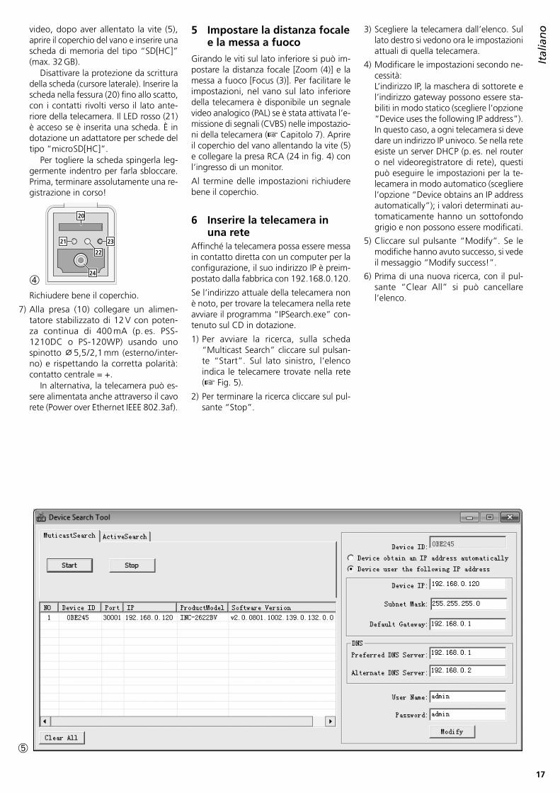
Italianovideo, dopo aver allentato la vite (5),
aprire il coperchio del vano e inserire una scheda di memoria del tipo “SD[HC]” (max . 32 GB) .
Disattivare la protezione da scrittura della scheda (cursore laterale) . Inserire la scheda nella fessura (20) fino allo scatto, con i contatti rivolti verso il lato ante-riore della telecamera . Il LED rosso (21) è acceso se è inserita una scheda . È in dotazione un adattatore per schede del tipo “micro SD[HC]” .
Per togliere la scheda spingerla leg-germente indentro per farla sbloccare . Prima, terminare assolutamente una re-gistrazione in corso!
➃
2321
22
24
20
Richiudere bene il coperchio .
7) Alla presa (10) collegare un alimen-tatore stabilizzato di 12 V con poten-za continua di 400 mA (p . es . PSS-1210DC o PS-120WP) usando uno spinotto ⌀ 5,5 / 2,1 mm (esterno / inter-no) e rispettando la corretta polarità: contatto centrale = + .
In alternativa, la telecamera può es-sere alimentata anche attraverso il cavo rete (Power over Ethernet IEEE 802 .3af) .
5 Impostare la distanza focale e la messa a fuoco
Girando le viti sul lato inferiore si può im-postare la distanza focale [Zoom (4)] e la messa a fuoco [Focus (3)] . Per facilitare le impostazioni, nel vano sul lato inferiore della telecamera è disponibile un segnale video analogico (PAL) se è stata attivata l’e-missione di segnali (CVBS) nelle impostazio-ni della telecamera (☞ Capitolo 7) . Aprire il coperchio del vano allentando la vite (5) e collegare la presa RCA (24 in fig . 4) con l’ingresso di un monitor .
Al termine delle impostazioni richiudere bene il coperchio .
6 Inserire la telecamera in una rete
Affinché la telecamera possa essere messa in contatto diretta con un computer per la configurazione, il suo indirizzo IP è preim-postato dalla fabbrica con 192 .168 .0 .120 .
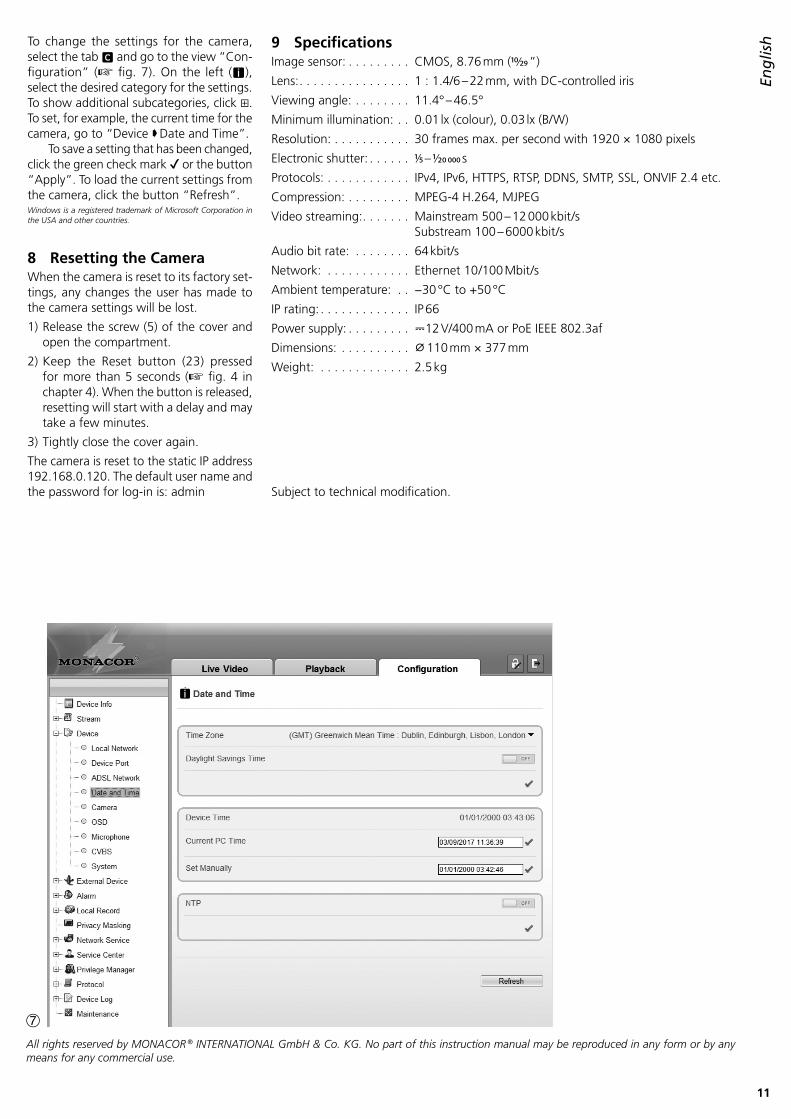
Se l’indirizzo attuale della telecamera non è noto, per trovare la telecamera nella rete avviare il programma “IPSearch .exe” con-tenuto sul CD in dotazione .
1) Per avviare la ricerca, sulla scheda “Multicast Search” cliccare sul pulsan-te “Start” . Sul lato sinistro, l’elenco indica le telecamere trovate nella rete (☞ Fig . 5) .
2) Per terminare la ricerca cliccare sul pul-sante “Stop” .
3) Scegliere la telecamera dall’elenco . Sul lato destro si vedono ora le impostazioni attuali di quella telecamera .
4) Modificare le impostazioni secondo ne-cessità: L’indirizzo IP, la maschera di sottorete e l’indirizzo gateway possono essere sta-biliti in modo statico (scegliere l’opzione “Device uses the following IP address”) . In questo caso, a ogni telecamera si deve dare un indirizzo IP univoco . Se nella rete esiste un server DHCP (p . es . nel router o nel videoregistratore di rete), questi può eseguire le impostazioni per la te-lecamera in modo automatico (scegliere l’opzione “Device obtains an IP address automatically”); i valori determinati au-tomaticamente hanno un sottofondo grigio e non possono essere modificati .
5) Cliccare sul pulsante “Modify” . Se le modifiche hanno avuto successo, si vede il messaggio “Modify success!” .
6) Prima di una nuova ricerca, con il pul-sante “Clear All” si può cancellare l’elenco .
➄

18
Italiano 7 Attivare la telecamera da
un computerL’interfaccia utente della telecamera può essere attivata digitando il suo indirizzo IP nella riga degli indirizzi del programma Windows Internet Explorer (IE, versione 6 o maggiore) . In questo caso, gli indirizzi IP del computer e della telecamera devono essere della stessa sottorete . Sono possibili al massimo 6 accessi contemporanei alla telecamera .
Attivando la telecamera, si vede all’i-nizio la finestra del login dove si sceglie la lingua per l’interfaccia utente; la descri-zione seguente si riferisce all’impostazione “English” . Quindi digitare il nome utente e la password (per entrambi è preimpostato: admin) . Nelle impostazioni della telecamera si possono determinare più tardi i propri dati per il login .Importante: Per proteggersi contro l’accesso non
autorizzato si dovrebbe cambiare per lo meno la password .
Una rappresentazione semplice dell’im-magine della telecamera è possibile con l’estensione del Flash-player di Adobe presente su molti computer (anche sul CD in dotazione) . Per una trasmissione più veloce dell’immagine e per poter utiliz-zare tutte le funzioni è richiesta tuttavia l’installazione delle estensioni ActiveX . Queste vengono caricate dalla telecamera al momento del primo clic sulla riga g di cambio Flash /Active (☞ Fig . 6) . Se neces-sario occorre allentare le impostazioni di sicurezza dell’IE in modo che questa pro-
➅
f
e a
g
h
b c d
cedura venga ammessa . Salvare sul computer il file d’installazione “webPlugins .exe”, chiudere l’IE e eseguire il file .
Se la connessione con la telecamera è stabile, si vede l’immagine attuale della telecamera come rappresentata in fig . 6 e con le seguenti possibilità di comando:
a Visione “Live Video” con l’immagine della telecamera
b Visione “Playback” per riprodurre le registrazioni dalla telecamera
c Visione “Configuration” per modificare le impostazioni della telecamera
d Pulsante per modificare la password
e Pulsante per il logout
f Immagine della telecamera con informazioni sullo stream attualmente trasmesso
g Per cambiare fra Flash-Player e ActiveX per la rappresentazione dell’immagine dal vivo, cliccare su questa riga .
h Barra degli strumenti con le seguenti funzioni
/ : Termine / avvio della trasmissione dell’immagine
“Stream”: Selezione di uno stream (per una modifica terminare con la trasmissione di uno stream in corso)
: Attivare /disattivare la trasmissione audio dalla telecamera [Audio Input (11)]
: Attivare /disattivare la trasmissione audio verso la telecamera [Audio Output (12)]
: Impostazioni specifiche della telecamera (p . es . regolazione dell’illuminazione, rispecchiamento)
: Funzione registrazione istantanea per memorizzare una ripresa momentanea come immagine
Cliccando con il tasto destro del mouse sull’immagine della telecamera si vede il seguente menu:
Voce del menu Funzione
Full Screen (Exit Full Screen)(Terminare) la visione a schermo intero,in alternativa: doppio clic sull’immagine
Sensor come
Zoom In / OutZoom in / outIn alternativa: zoomare con il ruotino del mouse oppure trarre una cornice sul settore richiesto dell’immagine
Restore Panorama Mostrare l’immagine intera (dopo zoom In)

19
Italiano9 Dati tecnici
Sensore ottico: . . . . . . . . CMOS, 8,76 mm (10⁄29 ”)
Obiettivo: . . . . . . . . . . . . 1 : 1,4 / 6 – 22 mm, con diaframma regolato
Angolo visivo: . . . . . . . . . 11,4° – 46,5°
Illuminazione minima: . . . 0,01 lx (colore), 0,03 lx (b /n)
Risoluzione: . . . . . . . . . . max . 30 imm . / s con 1920 × 1080 pixel
Otturatore elettronico: . . 1⁄5 – 1/20 000 s
Protocolli: . . . . . . . . . . . . IPv4, IPv6, HTTPS, RTSP, DDNS, SMTP, SSL, ONVIF 2 .4 et . al .
Compressione immagini: . MPEG-4 H .264, MJPEG
Videostreaming: . . . . . . . Mainstream 500 – 12 000 kbit /s Substream 100 – 6000 kbit /s
Bitrate audio: . . . . . . . . . 64 kbit /s
Network: . . . . . . . . . . . . Ethernet 10 / 100 Mbit / s
Temperatura d’esercizio: . −30 °C a +50 °C
Grado di protezione: . . . . IP 66
Alimentazione: . . . . . . . . ⎓12 V/400 mA opp . PoE IEEE 802 .3af
Dimensioni: . . . . . . . . . . . ⌀ 110 mm × 377 mm
Peso: . . . . . . . . . . . . . . . . 2,5 kg
Con riserva di modifiche tecniche .
Per modificare le impostazioni per la tele-camera, tramite il cavalierino c passare alla vista “Configuration” (☞ Fig . 7) . Sul bordo sinistro (i) selezionare la rubrica desiderata per le impostazioni . Cliccando su ⊞ si possono visualizzare ulteriori sotto-rubriche . Per esempio, con “Device Date and Time” si può impostare l’ora attuale per la telecamera .
Dopo la modifica di un’impostazione e per salvare la modifica cliccare sul segno verde di spunta ✔ oppure sul pulsante “Apply” . Per caricare le impostazioni at-tuali dalla telecamera, cliccare sul pulsante “Refresh” .Windows è un marchio registrato della Microsoft Corporation negli USA e in altre nazioni.
8 Reset della telecameraÈ possibile resettare la telecamera alle im-postazioni della fabbrica . In questo caso, tutte le modifiche delle impostazioni effet-tuate dall’utente vanno perse .
1) Allentare la vite (5) del coperchio e aprire il vano .
2) Premere per più di 5 secondi il pulsante Reset (23) (☞ Fig . 4 in capitolo 4) . Il processo di reset si avvia con un ritar-do dopo aver lasciato il pulsante e può impiegare alcuni minuti .
3) Richiudere bene il coperchio .
Ora, la telecamera è nuovamente impostata con l’indirizzo IP statico 192 .168 .0 .120, il nome utente e la password per il login sono: admin
i
➆La MONACOR ® INTERNATIONAL GmbH & Co. KG si riserva ogni diritto di elaborazione in qualsiasi forma delle presenti istruzioni per l’uso. La riproduzione – anche parziale – per propri scopi commerciali è vietata.

MONACOR INTERNATIONAL GmbH & Co. KG • Zum Falsch 36 • 28307 Bremen • GermanyCopyright© by MONACOR INTERNATIONAL. All rights reserved. A-1788 .99 .01 .07 .2017


![Latente Steuern WS 13-14.ppt [Kompatibilit tsmodus] · PDF file– nach IAS 2 dürfen nur fertigungsbezogene Verwaltungskosten aktiviert werden Bewertung der Pensionsverpflichtungen](https://static.fdocuments.in/doc/165x107/5a9ddefb7f8b9a4a238b9364/latente-steuern-ws-13-14ppt-kompatibilit-tsmodus-nach-ias-2-drfen-nur-fertigungsbezogene.jpg)