Networks: ATM1 ATM Asynchronous Transfer Mode. Networks: ATM2 Issues Driving LAN Changes Traffic...
32
Networks: ATM 1 ATM Asynchronous Transfer Mode
-
date post
19-Dec-2015 -
Category
Documents
-
view
231 -
download
1
Transcript of Networks: ATM1 ATM Asynchronous Transfer Mode. Networks: ATM2 Issues Driving LAN Changes Traffic...

Networks: ATM 1
ATM
Asynchronous Transfer Mode
Networks: ATM 2
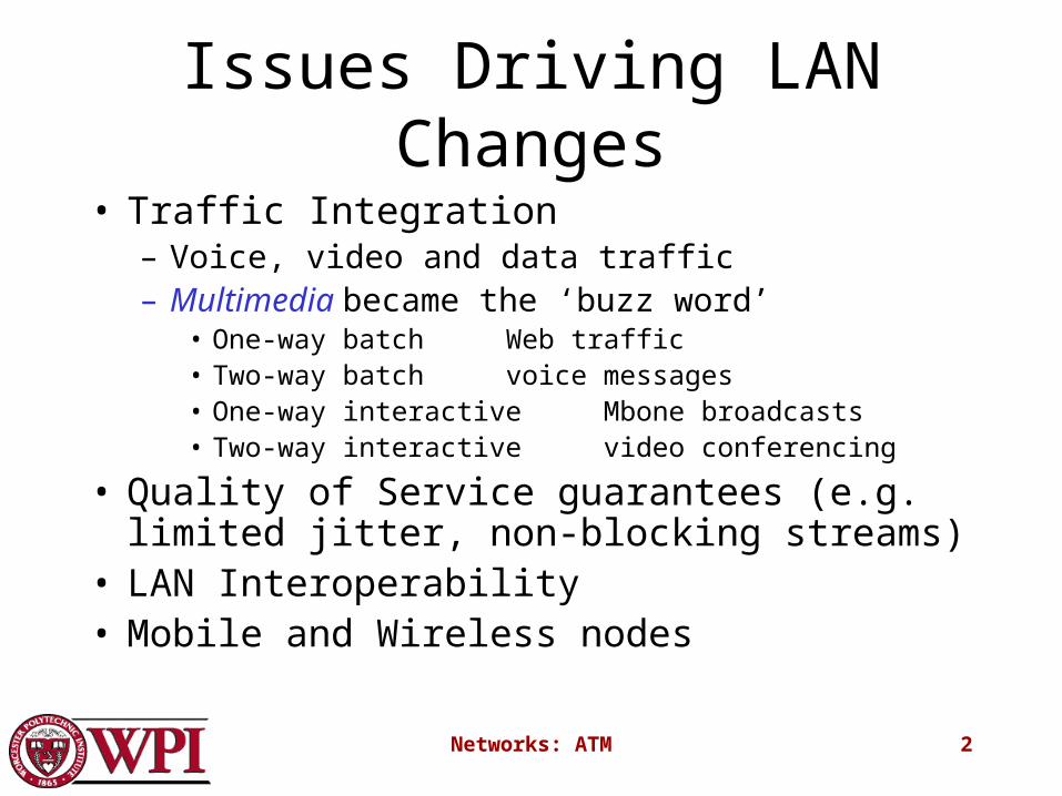
Issues Driving LAN Changes
• Traffic Integration– Voice, video and data traffic– Multimedia became the ‘buzz word’
• One-way batch Web traffic• Two-way batch voice messages• One-way interactive Mbone broadcasts• Two-way interactive video conferencing
• Quality of Service guarantees (e.g. limited jitter, non-blocking streams)
• LAN Interoperability• Mobile and Wireless nodes

Networks: ATM 3
Stallings “High-Speed Networks”

Networks: ATM 4
Stallings “High-Speed Networks”
Networks: ATM 5
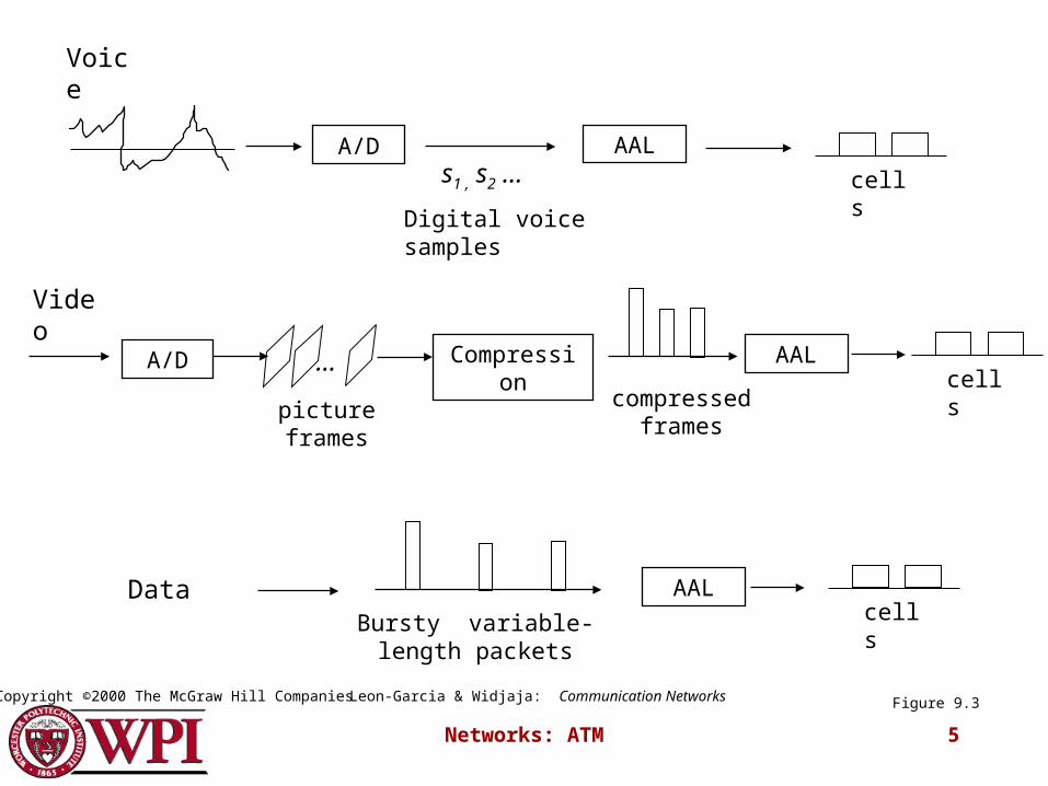
A/D AAL
Voice
s1 , s2 …
Digital voice samples
A/D AAL
Video
… Compression
compressed frames
picture frames
AALDataBursty variable-length
packets
cells
cells
cells
Figure 9.3Leon-Garcia & Widjaja: Communication NetworksCopyright ©2000 The McGraw Hill Companies
Networks: ATM 6
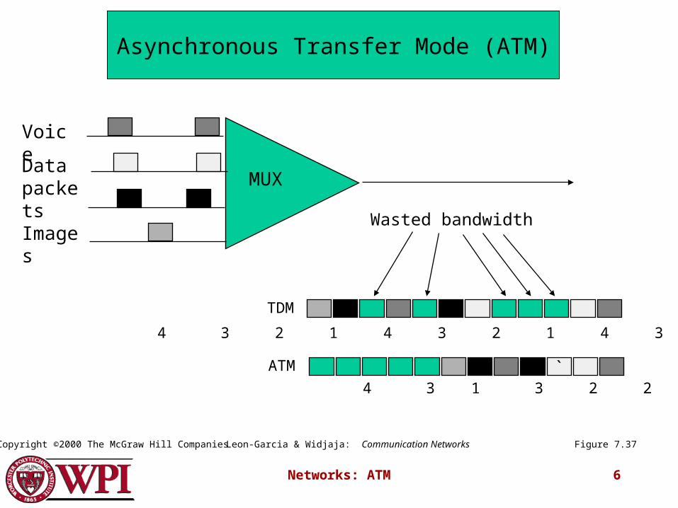
MUX
`
Wasted bandwidth
ATM
TDM
4 3 2 1 4 3 2 1 4 3 2 1
4 3 1 3 2 2 1
Voice
Data packets
Images
Figure 7.37
Asynchronous Transfer Mode (ATM)
Leon-Garcia & Widjaja: Communication NetworksCopyright ©2000 The McGraw Hill Companies
Networks: ATM 7
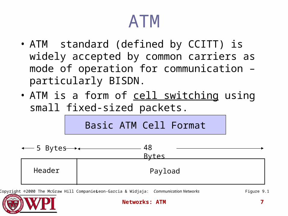
ATM• ATM standard (defined by CCITT) is widely
accepted by common carriers as mode of operation for communication – particularly BISDN.
• ATM is a form of cell switching using small fixed-sized packets.
Header Payload
5 Bytes 48 Bytes
Figure 9.1
Basic ATM Cell Format
Leon-Garcia & Widjaja: Communication NetworksCopyright ©2000 The McGraw Hill Companies

Networks: ATM 8
ATM Conceptual ModelFour Assumptions
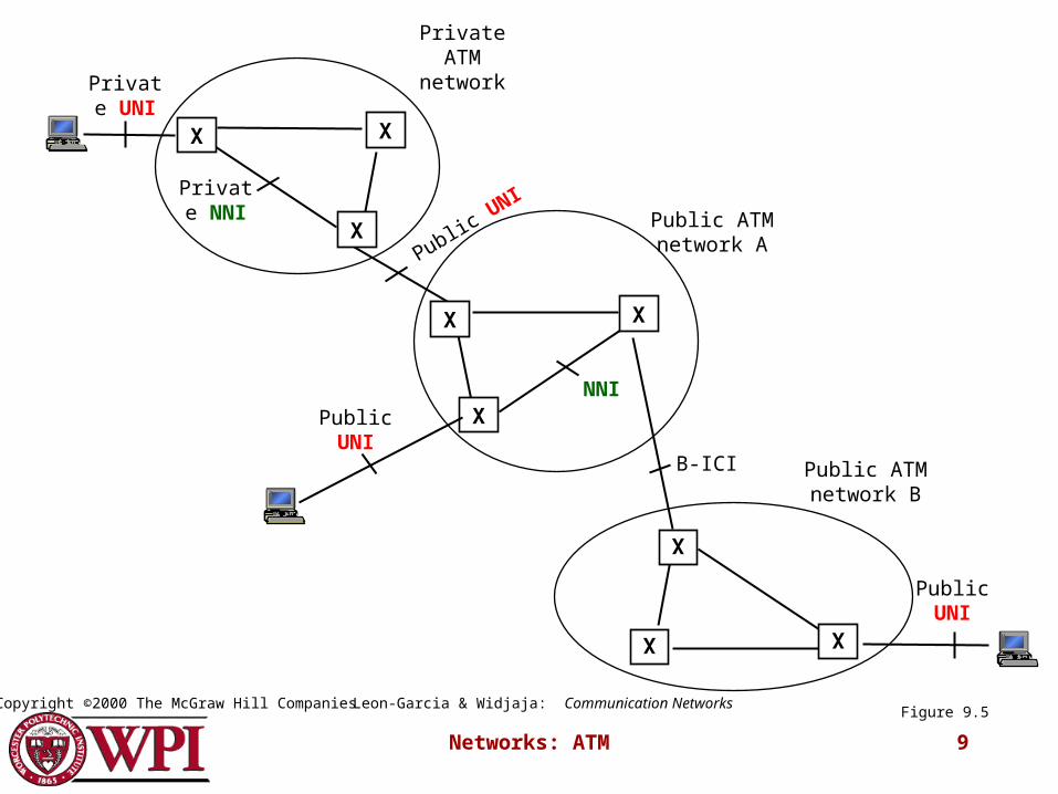
1. ATM network will be organized as a hierarchy.
User’s equipment connects to networks via a UNI (User-Network Interface).
Connections between provided networks are made through NNI (Network-Network Interface).
2. ATM will be connection-oriented.A connection (an ATM channel) must be established before any cells are sent.
Networks: ATM 9
X
X
X
X
X
X
X
X
X
Private UNI
Public UNI
NNI
Private NNI
Private ATM network
Public UNI
B-ICI
Public UNIPublic ATM network A
Public ATM network B
Figure 9.5Leon-Garcia & Widjaja: Communication NetworksCopyright ©2000 The McGraw Hill Companies

Networks: ATM 10
ATM Connections
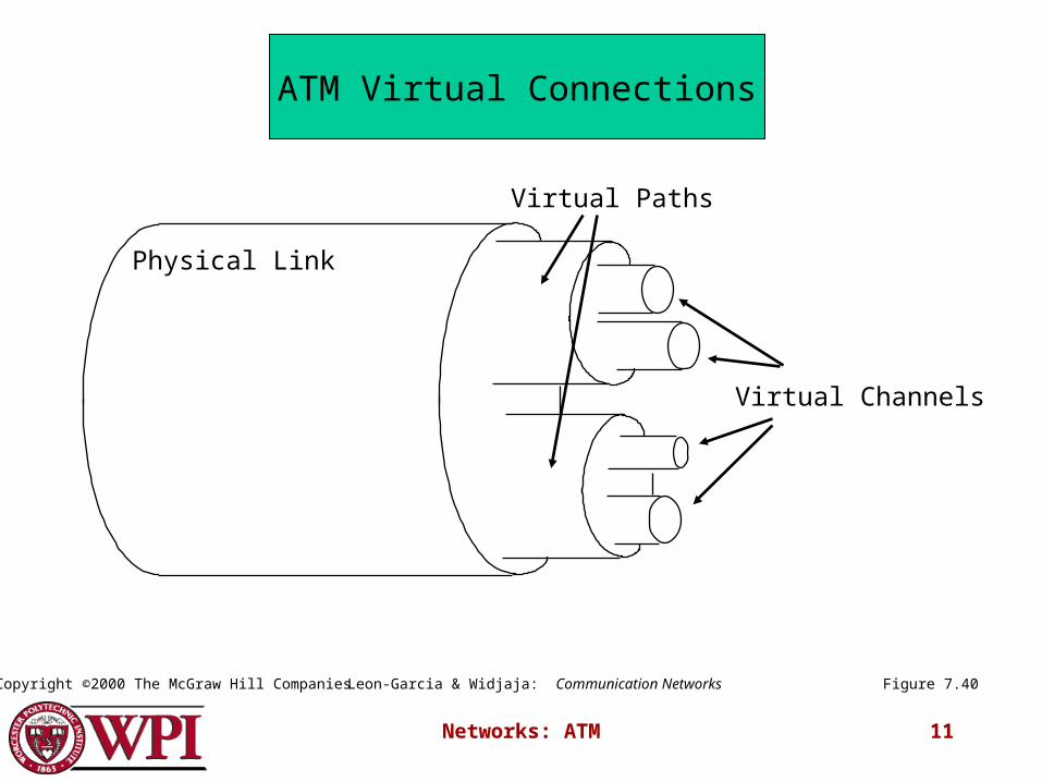
• two levels of ATM connections:
virtual path connections
virtual channel connections
• indicated by two fields in the cell header:
virtual path identifier VPI
virtual channel identifier VCI
Networks: ATM 11
Physical Link
Virtual Paths
Virtual Channels
Figure 7.40
ATM Virtual Connections
Leon-Garcia & Widjaja: Communication NetworksCopyright ©2000 The McGraw Hill Companies
Networks: ATM 12
ATM Conceptual Model Assumptions (cont.)
3. Vast majority of ATM networks will run on optical fiber networks with extremely low error rates.
4. ATM must supports low cost attachments• This decision lead to a significant decision – to
prohibit cell reordering in ATM networks.
ATM switch design is more difficult.
Networks: ATM 13
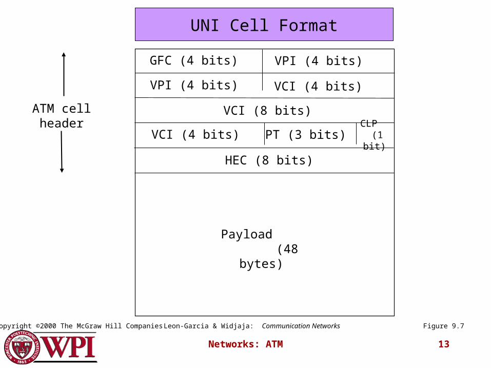
GFC (4 bits) VPI (4 bits)
VPI (4 bits) VCI (4 bits)
VCI (8 bits)
VCI (4 bits) PT (3 bits) CLP (1 bit)
HEC (8 bits)
ATM cell header
Payload (48 bytes)
Figure 9.7
UNI Cell Format
Leon-Garcia & Widjaja: Communication NetworksCopyright ©2000 The McGraw Hill Companies

Networks: ATM 14
2
3
N
1Switch
N
1…
5
6
video 25
video
voice
data
32
32 61
25
32
3261
75
67
39
67
N
1
32
video 75
voice 67
data 39
video 67
Figure 7.38
…
…
ATM Cell Switching
Leon-Garcia & Widjaja: Communication NetworksCopyright ©2000 The McGraw Hill Companies
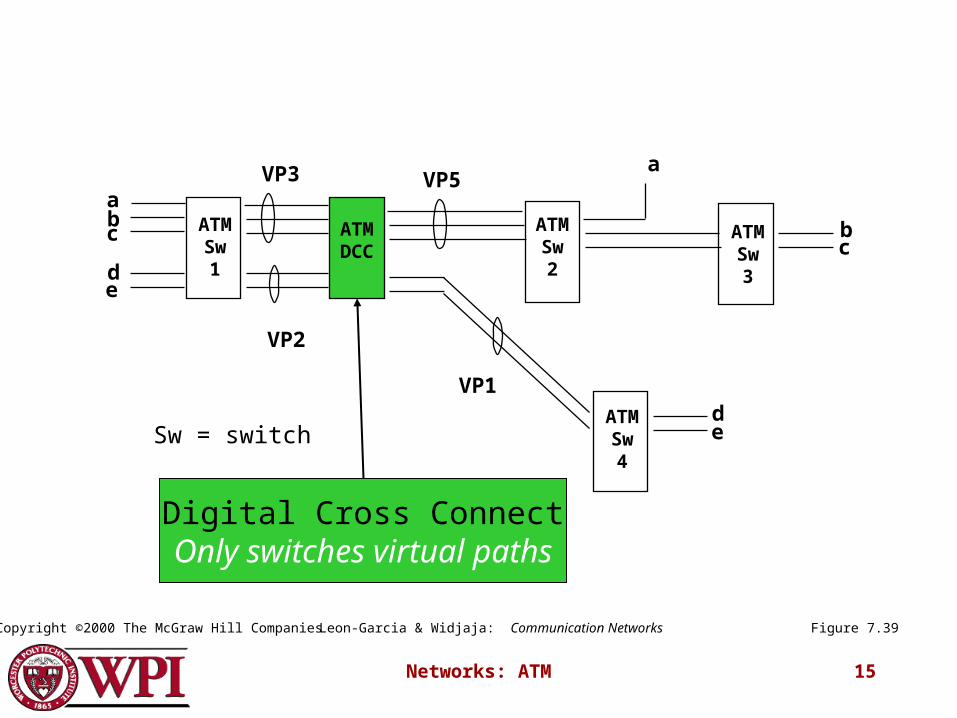
Networks: ATM 15
c ATMSw1
ATMSw4
ATMSw2
ATMSw3
ATMDCC
ab
de
VP3 VP5
VP2
VP1
a
bc
deSw = switch
Figure 7.39
Digital Cross ConnectOnly switches virtual paths
Leon-Garcia & Widjaja: Communication NetworksCopyright ©2000 The McGraw Hill Companies
Networks: ATM 16
ATM Protocol Architecture
• ATM Adaptation Layer (AAL) – the protocol for packaging data into cells is collectively referred to as AAL.
• Must efficiently package higher level data such as voice samples, video frames and datagram packets into a series of cells.
Design Issue: How many adaptation layers should there be?

Networks: ATM 17
Plane managem
entManagement plane
Control plane User plane
Physical layer
ATM layer
ATM adaptation layer
Higher layers Higher layers
Layer m
anagement
Figure 9.2Leon-Garcia & Widjaja: Communication NetworksCopyright ©2000 The McGraw Hill Companies

Networks: ATM 18
AAL
ATM
User information
User information
AAL
ATM
PHYPHY
ATM
PHY
ATM
PHY
…
End system End systemNetwork
Figure 9.4Leon-Garcia & Widjaja: Communication NetworksCopyright ©2000 The McGraw Hill Companies

Networks: ATM 19
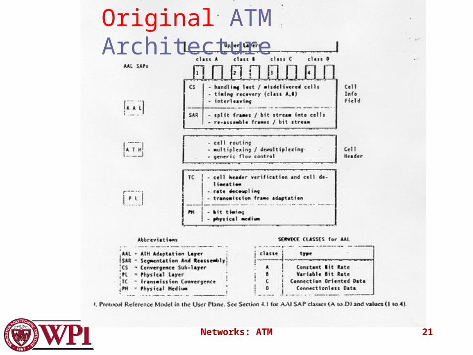
Original ATM Architecture
• CCITT envisioned four classes of applications (A-D) requiring four distinct adaptation layers (1-4) which would be optimized for an application class:
A. Constant bit-rate applications CBR
B. Variable bit-rate applications VBR
C. Connection-oriented data applications
D. Connectionless data application
Networks: ATM 20
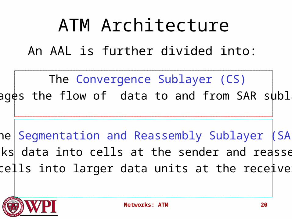
ATM ArchitectureAn AAL is further divided into:
The Convergence Sublayer (CS)
manages the flow of data to and from SAR sublayer.
The Segmentation and Reassembly Sublayer (SAR)
breaks data into cells at the sender and reassembles
cells into larger data units at the receiver.
Networks: ATM 21
Original ATM Architecture
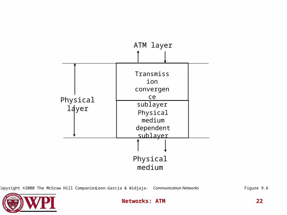
Networks: ATM 22
Transmission convergence
sublayer
Physical medium dependent sublayer
Physical medium
ATM layer
Physical layer
Figure 9.6Leon-Garcia & Widjaja: Communication NetworksCopyright ©2000 The McGraw Hill Companies

Networks: ATM 23
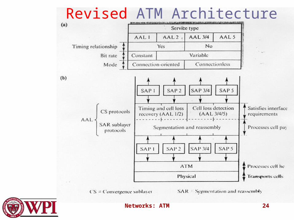
• The AAL interface was initially defined as classes A-D with SAP (service access points) for AAL1-4.
• AAL3 and AAL4 were so similar that they were merged into AAL3/4.
• The data communications community concluded that AAL3/4 was not suitable for data communications applications. They pushed for standardization of AAL5 (also referred to as SEAL – the Simple and Efficient Adaptation Layer).
• AAL2 was not initially deployed.
Original ATM Architecture
Networks: ATM 24
Revised ATM Architecture

Networks: ATM 25
Revised ATM Service Categories
Class Description Example
CBR Constant Bit Rate T1 circuit
RT-VBR Real Time Variable Bit Rate
Real-time videoconferencing
NRT-VBR Non-real-time Variable Bit Rate
Multimedia email
ABR Available Bit Rate Browsing the Web
UBR Unspecified Bit Rate Background file transfer

Networks: ATM 26
QoS, PVC, and SVC• Quality of Service (QoS) requirements are
handled at connection time and viewed as part of signaling.
• ATM provides permanent virtual connections and switched virtual connections.– Permanent Virtual Connections (PVC)
permanent connections set up manually by network manager.
– Switched Virtual Connections (SVC) set up and released on demand by the end user
via signaling procedures.
Networks: ATM 27
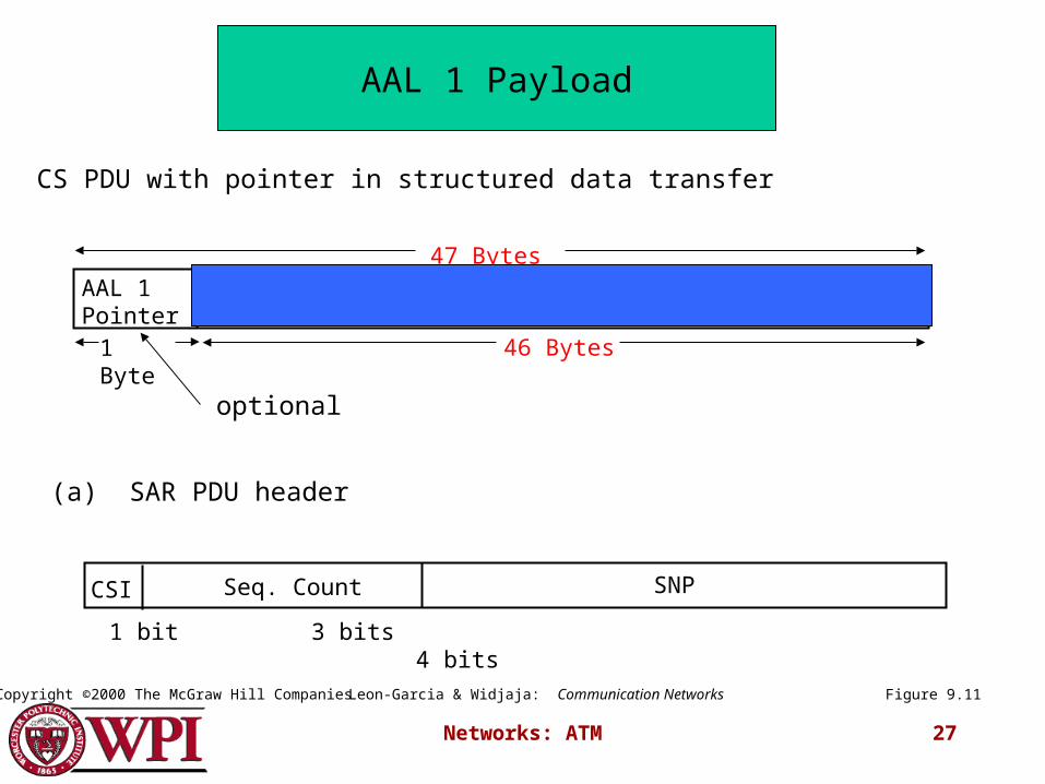
(b) CS PDU with pointer in structured data transfer
AAL 1 Pointer
1 Byte 46 Bytes
47 Bytes
Figure 9.11
AAL 1 Payload
Leon-Garcia & Widjaja: Communication NetworksCopyright ©2000 The McGraw Hill Companies
optional
(a) SAR PDU header
CSI SNPSeq. Count
1 bit 3 bits 4 bits
Networks: ATM 28
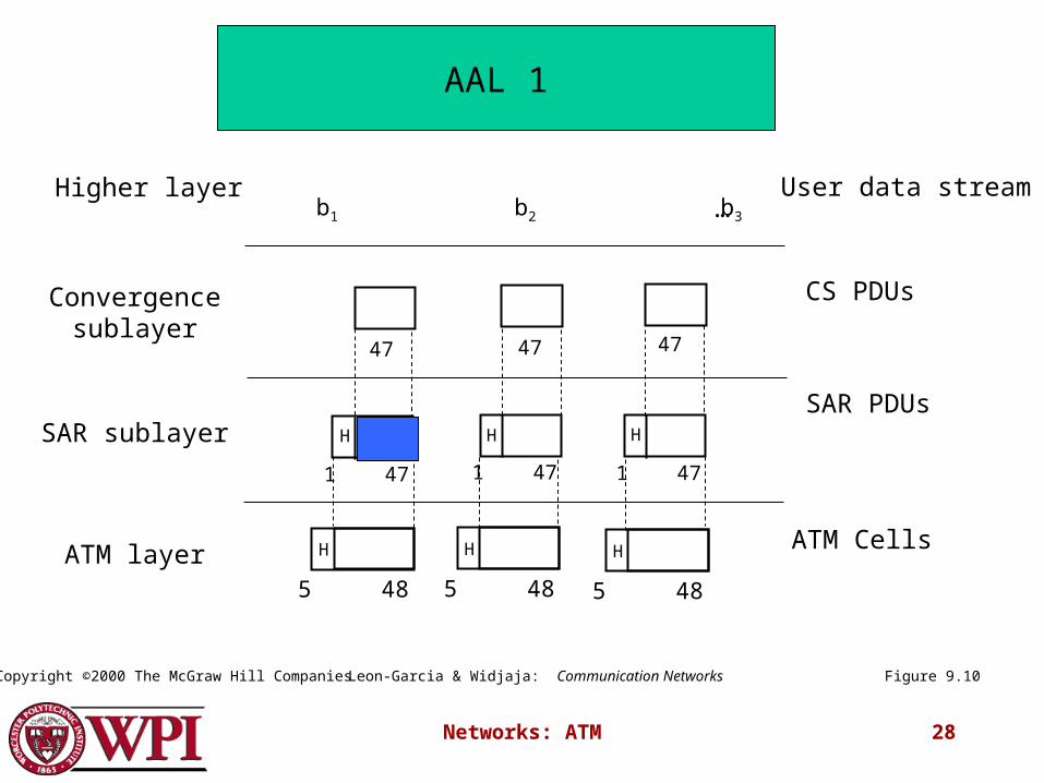
…Higher layer User data stream
Convergence sublayer
SAR sublayer
ATM layer
CS PDUs
SAR PDUs
ATM Cells
47 47 47
1 47 1 47 1 47
H H H
5 48
H
5 48
H
5 48
H
b1 b2 b3
Figure 9.10
AAL 1
Leon-Garcia & Widjaja: Communication NetworksCopyright ©2000 The McGraw Hill Companies
Networks: ATM 29
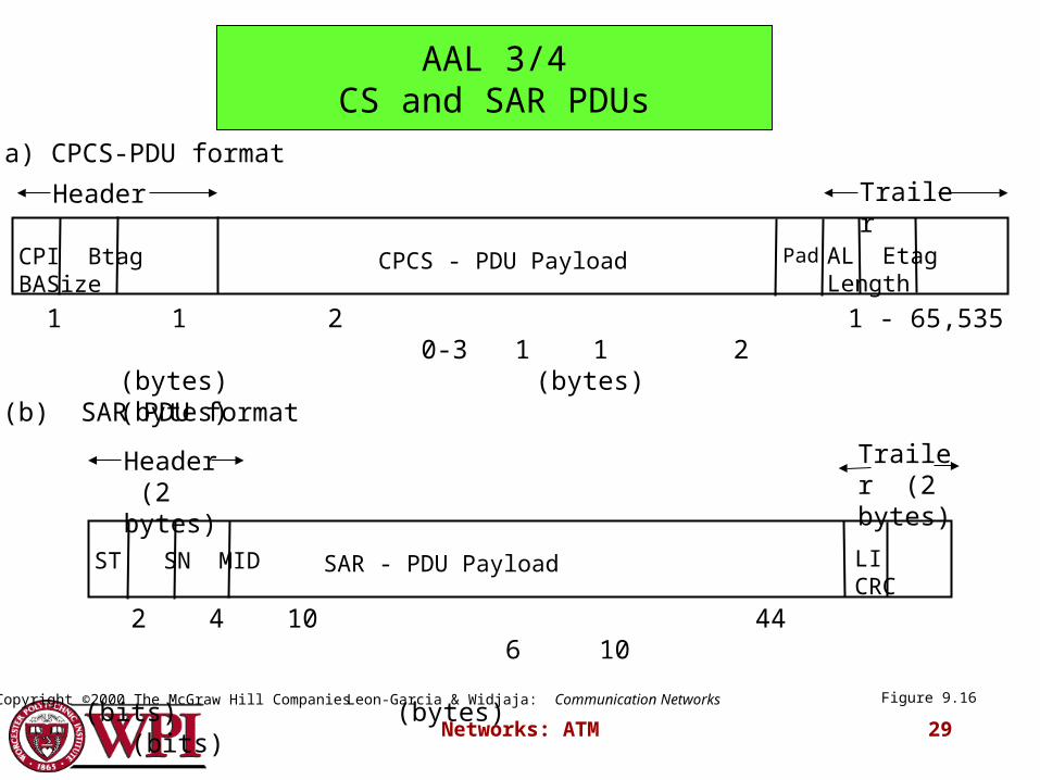
(a) CPCS-PDU format
(b) SAR PDU format
CPI Btag BASize CPCS - PDU Payload
1 1 2 1 - 65,535 0-3 1 1 2 (bytes) (bytes) (bytes)
AL Etag LengthPad
Header Trailer
ST SN MID SAR - PDU Payload
2 4 10 44 6 10 (bits) (bytes)
(bits)
LI CRC
Header (2 bytes)
Trailer (2 bytes)
Figure 9.16
AAL 3/4CS and SAR PDUs
Leon-Garcia & Widjaja: Communication NetworksCopyright ©2000 The McGraw Hill Companies
Networks: ATM 30
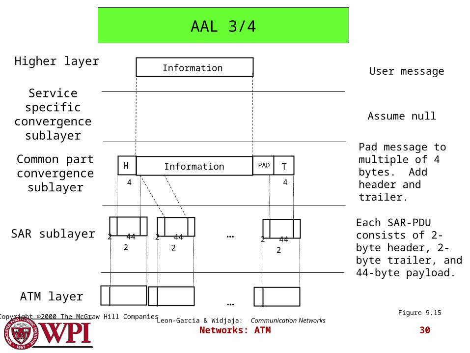
Higher layer
Common part convergence
sublayer
SAR sublayer
ATM layer
Service specific convergence
sublayer
Information
Assume null
TPAD
User message
Pad message to multiple of 4 bytes. Add header and trailer.
Each SAR-PDU consists of 2-byte header, 2-byte trailer, and 44-byte payload.
H
4 4
2 44 2 2 44 2 2 44 2
…
…
Information
Figure 9.15
AAL 3/4
Leon-Garcia & Widjaja: Communication NetworksCopyright ©2000 The McGraw Hill Companies
Networks: ATM 31
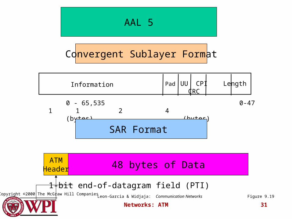
Information
0 - 65,535 0-47 1 1 2 4 (bytes) (bytes)
UU CPI Length CRCPad
Figure 9.19
AAL 5
Convergent Sublayer Format
SAR Format
48 bytes of DataATMHeader
1-bit end-of-datagram field (PTI)Leon-Garcia & Widjaja: Communication Networks
Copyright ©2000 The McGraw Hill Companies
Networks: ATM 32
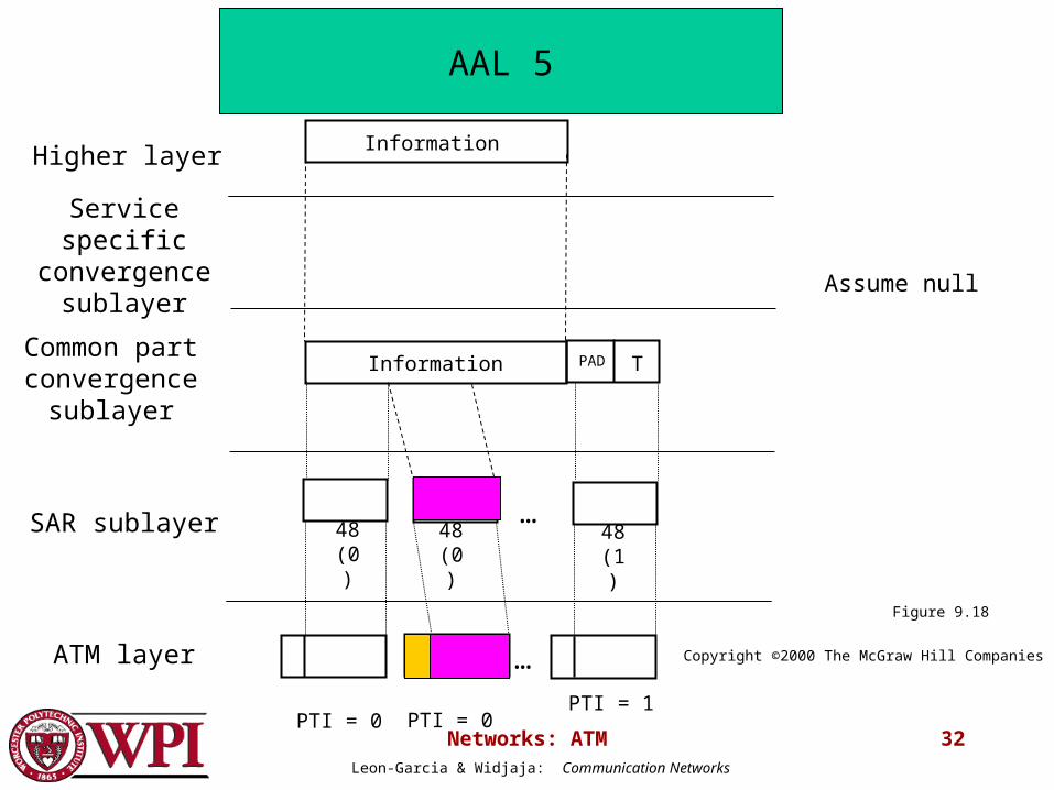
Higher layer
Common part convergence
sublayer
SAR sublayer
ATM layer
PTI = 0
Service specific convergence
sublayer Assume null
48 (1)
Information
TPAD
…
…
Information
48 (0)
48 (0)
PTI = 0PTI = 1
Figure 9.18
AAL 5
Leon-Garcia & Widjaja: Communication Networks
Copyright ©2000 The McGraw Hill Companies