Network Switch Setup for Q-SYS Platform · Revision 1.3—4 April 2018 3 Network Switch Setup for...
10
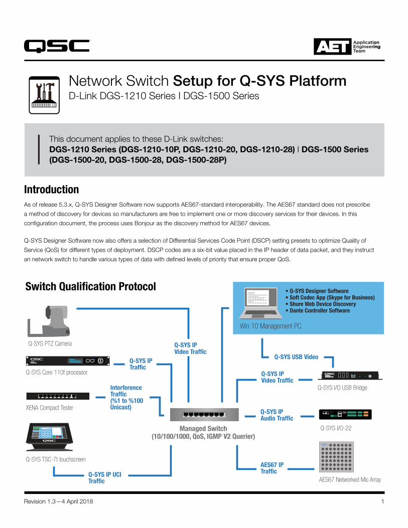
1 Revision 1.3—4 April 2018 Introduction As of release 5.3.x, Q-SYS Designer Software now supports AES67-standard interoperability. The AES67 standard does not prescribe a method of discovery for devices so manufacturers are free to implement one or more discovery services for their devices. In this configuration document, the process uses Bonjour as the discovery method for AES67 devices. Q-SYS Designer Software now also offers a selection of Differential Services Code Point (DSCP) setting presets to optimize Quality of Service (QoS) for different types of deployment. DSCP codes are a six-bit value placed in the IP header of data packet, and they instruct an network switch to handle various types of data with defined levels of priority that ensure proper QoS. Switch Qualification Protocol Network Switch Setup for Q-SYS Platform D-Link DGS-1210 Series I DGS-1500 Series This document applies to these D-Link switches: DGS-1210 Series (DGS-1210-10P, DGS-1210-20, DGS-1210-28) I DGS-1500 Series (DGS-1500-20, DGS-1500-28, DGS-1500-28P) XENA Compact Tester Q-SYS TSC-7t touchscreen AES67 Networked Mic Array Q-SYS I/O-22 Q-SYS Core 110f processor Q-SYS PTZ Camera Win 10 Management PC Q-SYS IP UCI Traffic Q-SYS IP Video Traffic Interference Traffic (%1 to %100 Unicast) AES67 IP Traffic Q-SYS I/O USB Bridge Q-SYS IP Video Traffic Q-SYS IP Audio Traffic Q-SYS IP Traffic • Q-SYS Designer Software • Soft Codec App (Skype for Business) • Shure Web Device Discovery • Dante Controller Software Managed Switch (10/100/1000, QoS, IGMP V2 Querier) Q-SYS USB Video
-
Upload
truongphuc -
Category
Documents
-
view
225 -
download
1
Transcript of Network Switch Setup for Q-SYS Platform · Revision 1.3—4 April 2018 3 Network Switch Setup for...
1Revision 1.3—4 April 2018
IntroductionAs of release 5.3.x, Q-SYS Designer Software now supports AES67-standard interoperability. The AES67 standard does not prescribe
a method of discovery for devices so manufacturers are free to implement one or more discovery services for their devices. In this
configuration document, the process uses Bonjour as the discovery method for AES67 devices.
Q-SYS Designer Software now also offers a selection of Differential Services Code Point (DSCP) setting presets to optimize Quality of
Service (QoS) for different types of deployment. DSCP codes are a six-bit value placed in the IP header of data packet, and they instruct
an network switch to handle various types of data with defined levels of priority that ensure proper QoS.
Switch Qualification Protocol
Network Switch Setup for Q-SYS PlatformD-Link DGS-1210 Series I DGS-1500 Series
This document applies to these D-Link switches: DGS-1210 Series (DGS-1210-10P, DGS-1210-20, DGS-1210-28) I DGS-1500 Series (DGS-1500-20, DGS-1500-28, DGS-1500-28P)
XENA Compact Tester
Q-SYS TSC-7t touchscreen
AES67 Networked Mic Array
Q-SYS I/O-22
Q-SYS Core 110f processor
Q-SYS PTZ Camera
Win 10 Management PC
Q-SYS IP UCI Traffic
Q-SYS IP Video Traffic
Interference Traffic (%1 to %100 Unicast)
AES67 IP Traffic
Q-SYS I/O USB Bridge
Q-SYS IP Video Traffic
Q-SYS IP Audio Traffic
Q-SYS IP Traffic
• Q-SYS Designer Software• Soft Codec App (Skype for Business)• Shure Web Device Discovery• Dante Controller Software
Managed Switch (10/100/1000, QoS, IGMP V2 Querier)
Q-SYS USB Video
Revision 1.3—4 April 2018 2
Network Switch Setup for Q-SYS Platform D-Link DGS-1210 Series I DGS-1500 Series
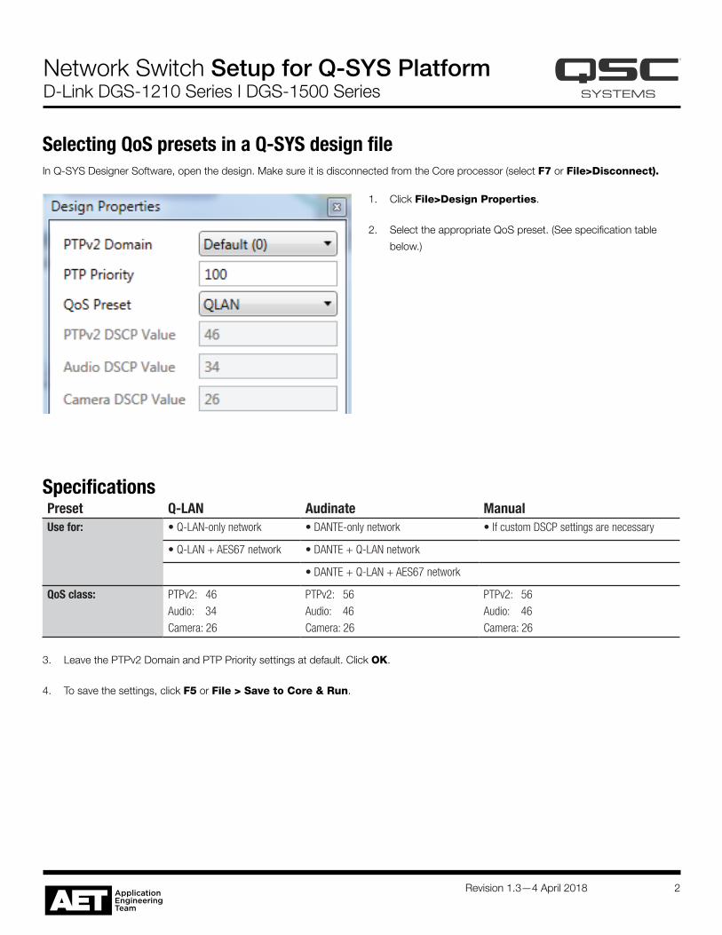
1. Click File>Design Properties.
2. Select the appropriate QoS preset. (See specification table
below.)
SpecificationsPreset Q-LAN Audinate ManualUse for: • Q-LAN-only network • DANTE-only network • If custom DSCP settings are necessary
• Q-LAN + AES67 network • DANTE + Q-LAN network
• DANTE + Q-LAN + AES67 network
QoS class: PTPv2: 46Audio: 34Camera: 26
PTPv2: 56Audio: 46Camera: 26
PTPv2: 56Audio: 46Camera: 26
3. Leave the PTPv2 Domain and PTP Priority settings at default. Click OK.
4. To save the settings, click F5 or File > Save to Core & Run.
Selecting QoS presets in a Q-SYS design fileIn Q-SYS Designer Software, open the design. Make sure it is disconnected from the Core processor (select F7 or File>Disconnect).
Revision 1.3—4 April 2018 3
Network Switch Setup for Q-SYS Platform D-Link DGS-1210 Series I DGS-1500 Series
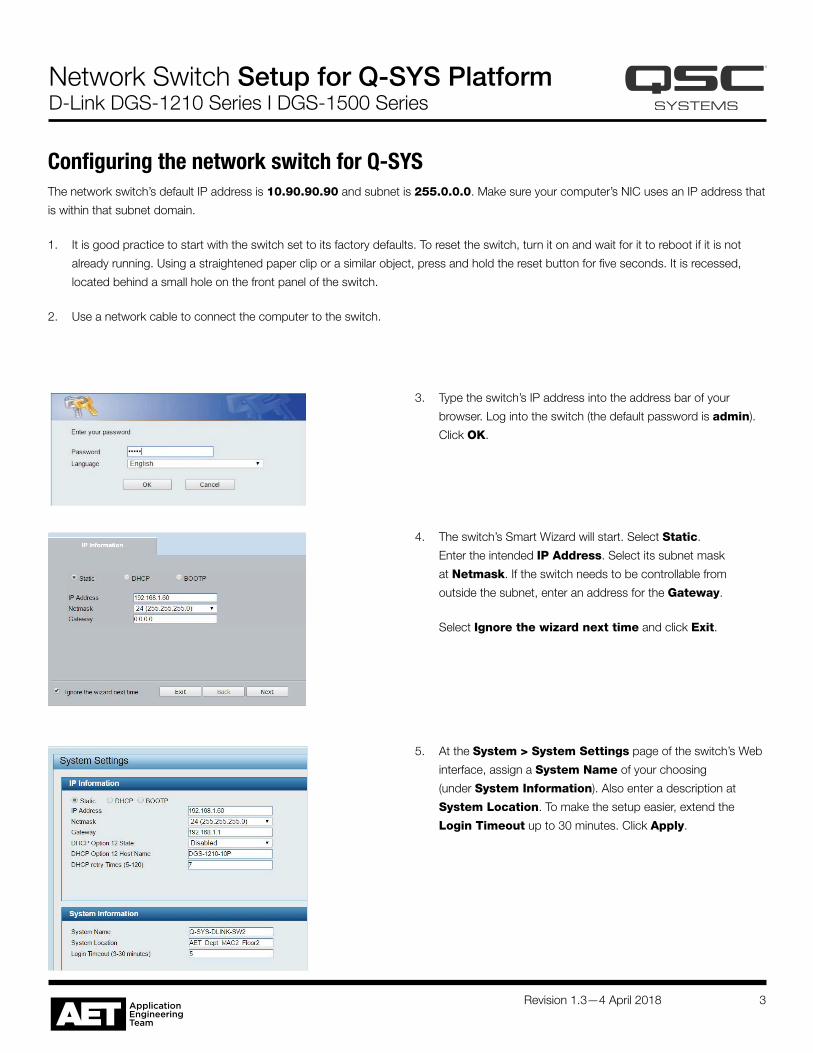
3. Type the switch’s IP address into the address bar of your
browser. Log into the switch (the default password is admin).
Click OK.
Configuring the network switch for Q-SYSThe network switch’s default IP address is 10.90.90.90 and subnet is 255.0.0.0. Make sure your computer’s NIC uses an IP address that
is within that subnet domain.
1. It is good practice to start with the switch set to its factory defaults. To reset the switch, turn it on and wait for it to reboot if it is not
already running. Using a straightened paper clip or a similar object, press and hold the reset button for five seconds. It is recessed,
located behind a small hole on the front panel of the switch.
2. Use a network cable to connect the computer to the switch.
4. The switch’s Smart Wizard will start. Select Static.
Enter the intended IP Address. Select its subnet mask
at Netmask. If the switch needs to be controllable from
outside the subnet, enter an address for the Gateway.
Select Ignore the wizard next time and click Exit.
5. At the System > System Settings page of the switch’s Web
interface, assign a System Name of your choosing
(under System Information). Also enter a description at
System Location. To make the setup easier, extend the
Login Timeout up to 30 minutes. Click Apply.
Revision 1.3—4 April 2018 4
Network Switch Setup for Q-SYS Platform D-Link DGS-1210 Series I DGS-1500 Series
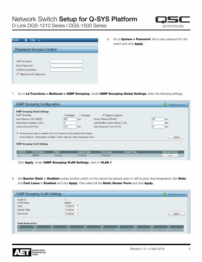
6. Go to System > Password. Set a new password for the
switch and click Apply.
7. Go to L2 Functions > Multicast > IGMP Snooping. Under IGMP Snooping Global Settings, enter the following settings:
8. Set Querier State to Enabled (unless another switch on the subnet has already been or will be given that designation). Set State
and Fast Leave to Enabled and click Apply. Then select all the Static Router Ports and click Apply.
Click Apply. Under IGMP Snooping VLAN Settings, click on VLAN 1.
Revision 1.3—4 April 2018 5
Network Switch Setup for Q-SYS Platform D-Link DGS-1210 Series I DGS-1500 Series
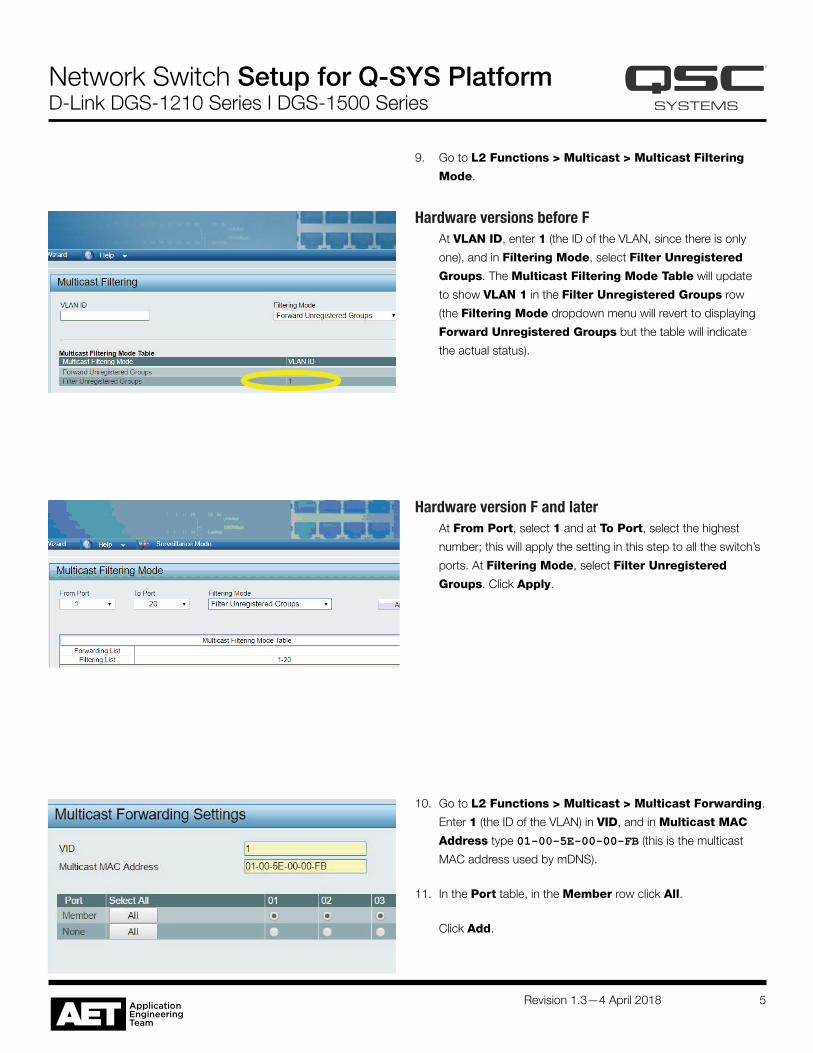
9. Go to L2 Functions > Multicast > Multicast Filtering
Mode.
Hardware versions before FAt VLAN ID, enter 1 (the ID of the VLAN, since there is only
one), and in Filtering Mode, select Filter Unregistered
Groups. The Multicast Filtering Mode Table will update
to show VLAN 1 in the Filter Unregistered Groups row
(the Filtering Mode dropdown menu will revert to displaying
Forward Unregistered Groups but the table will indicate
the actual status).
10. Go to L2 Functions > Multicast > Multicast Forwarding.
Enter 1 (the ID of the VLAN) in VID, and in Multicast MAC
Address type 01-00-5E-00-00-FB (this is the multicast
MAC address used by mDNS).
11. In the Port table, in the Member row click All.
Click Add.
Hardware version F and laterAt From Port, select 1 and at To Port, select the highest
number; this will apply the setting in this step to all the switch’s
ports. At Filtering Mode, select Filter Unregistered
Groups. Click Apply.
Revision 1.3—4 April 2018 6
Network Switch Setup for Q-SYS Platform D-Link DGS-1210 Series I DGS-1500 Series
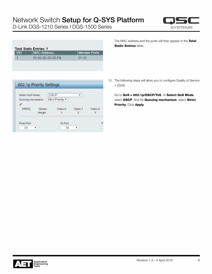
12. The following steps will allow you to configure Quality of Service
+ (QoS).
Go to QoS > 802.1p/DSCP/ToS. At Select QoS Mode,
select DSCP. And for Queuing mechanism, select Strict
Priority. Click Apply.
The MAC address and the ports will then appear in the Total
Static Entries table.
Revision 1.3—4 April 2018 7
Network Switch Setup for Q-SYS Platform D-Link DGS-1210 Series I DGS-1500 Series
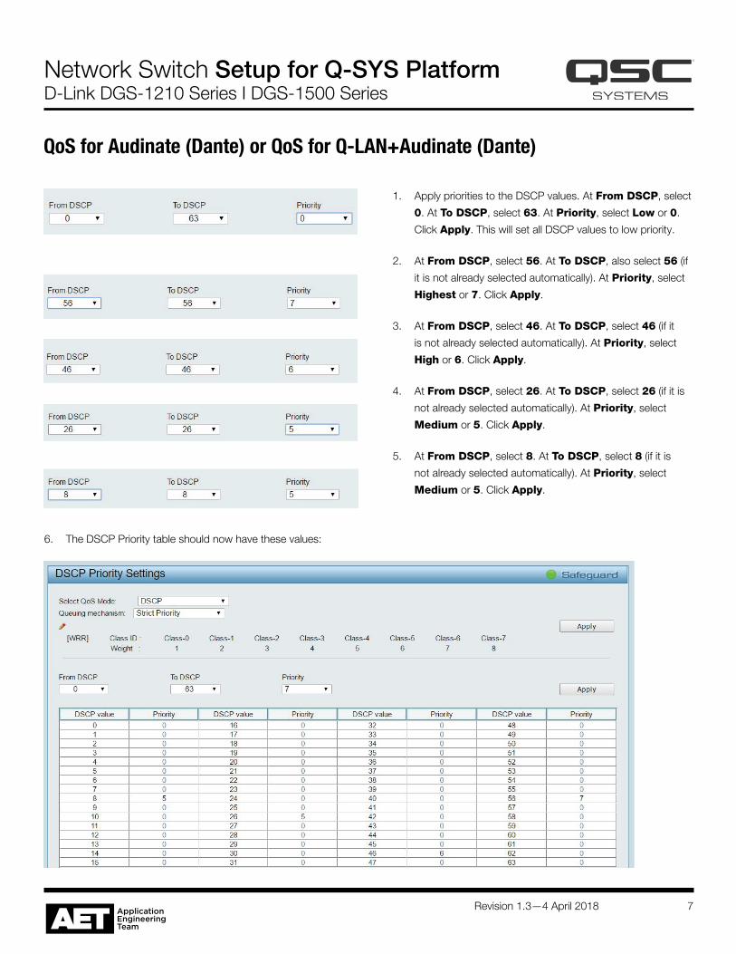
1. Apply priorities to the DSCP values. At From DSCP, select
0. At To DSCP, select 63. At Priority, select Low or 0.
Click Apply. This will set all DSCP values to low priority.
2. At From DSCP, select 56. At To DSCP, also select 56 (if
it is not already selected automatically). At Priority, select
Highest or 7. Click Apply.
3. At From DSCP, select 46. At To DSCP, select 46 (if it
is not already selected automatically). At Priority, select
High or 6. Click Apply.
4. At From DSCP, select 26. At To DSCP, select 26 (if it is
not already selected automatically). At Priority, select
Medium or 5. Click Apply.
5. At From DSCP, select 8. At To DSCP, select 8 (if it is
not already selected automatically). At Priority, select
Medium or 5. Click Apply.
QoS for Audinate (Dante) or QoS for Q-LAN+Audinate (Dante)
6. The DSCP Priority table should now have these values:
Revision 1.3—4 April 2018 8
Network Switch Setup for Q-SYS Platform D-Link DGS-1210 Series I DGS-1500 Series
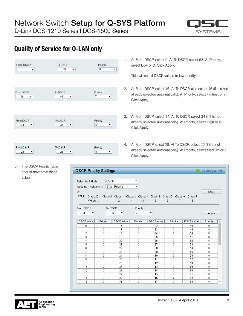
1. At From DSCP, select 0. At To DSCP, select 63. At Priority,
select Low or 0. Click Apply.
This will set all DSCP values to low priority.
Quality of Service for Q-LAN only
5. The DSCP Priority table
should now have these
values:
2. At From DSCP, select 46. At To DSCP, also select 46 (if it is not
already selected automatically). At Priority, select Highest or 7.
Click Apply.
3. At From DSCP, select 34. At To DSCP, select 34 (if it is not
already selected automatically). At Priority, select High or 6.
Click Apply.
4. At From DSCP select 26. At To DSCP, select 26 (if it is not
already selected automatically). At Priority, select Medium or 5.
Click Apply.
Revision 1.3—4 April 2018 9
Network Switch Setup for Q-SYS Platform D-Link DGS-1210 Series I DGS-1500 Series
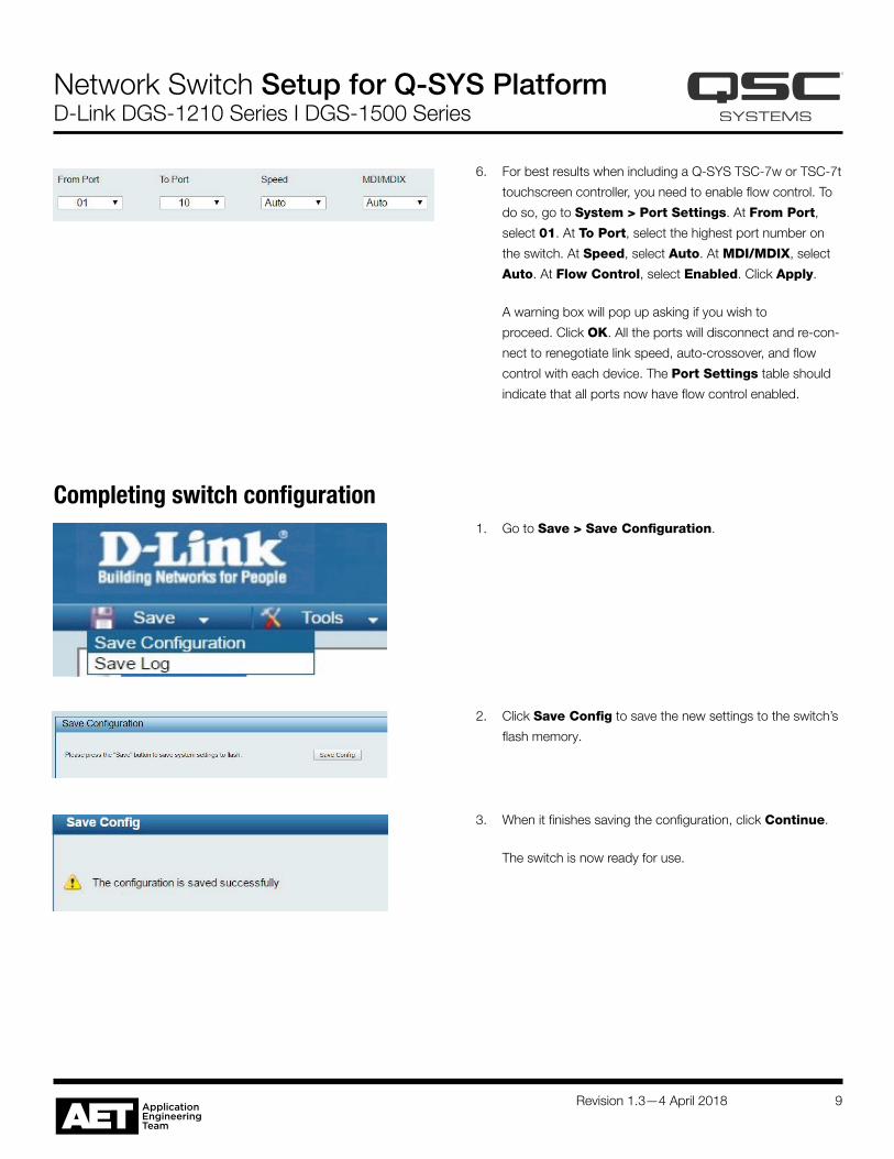
6. For best results when including a Q-SYS TSC-7w or TSC-7t
touchscreen controller, you need to enable flow control. To
do so, go to System > Port Settings. At From Port,
select 01. At To Port, select the highest port number on
the switch. At Speed, select Auto. At MDI/MDIX, select
Auto. At Flow Control, select Enabled. Click Apply.
A warning box will pop up asking if you wish to
proceed. Click OK. All the ports will disconnect and re-con-
nect to renegotiate link speed, auto-crossover, and flow
control with each device. The Port Settings table should
indicate that all ports now have flow control enabled.
1. Go to Save > Save Configuration.
Completing switch configuration
2. Click Save Config to save the new settings to the switch’s
flash memory.
3. When it finishes saving the configuration, click Continue.
The switch is now ready for use.
Revision 1.3—4 April 2018 10
© 2018 QSC, LLC. All rights reserved. QSC, Q-SYS, and the QSC logo are registered trademarks in the U.S. Patent and Trademark Office and other countries. Dante™ is a trademark of Audinate Pty Ltd. SHURE is a trademark of Shure Incorporated.qsc.com
Network Switch Setup for Q-SYS Platform D-Link DGS-1210 Series I DGS-1500 Series
Troubleshooting discovery issuesThis setup procedure for these D-Link switches will work for most Q-SYS applications. For reasons we haven’t yet found, though, some
systems have exhibited problems with discovery processes with these settings. Here are some examples of these problems:
• Q-SYS Configurator fails to list one or more core processors that are on the network
• Dante™ Controller does not see AES67 or Dante devices on the network
• The SHURE ® Web Discovery application does not see devices on the network
If you encounter these or similar network discovery problems when using a switch configured according to this setup guide, there are a
couple steps to try. First, log into the switch as instructed in this setup guide.
1. Disable IGMP snooping. To do this, go to L2 Functions > Multicast > IGMP Snooping (see page 4, step 7). Under IGMP
Snooping Global Settings, select Disabled. Save the configuration.
Possible complications: Disabling IGMP snooping might affect performance in QSC PTZ cameras on the network by slowing down
their video frame rate. If your network has a PTZ camera, open its control box in Q-SYS Designer and observe the frame rate indicated
while you disable IGMP snooping in the switch setup window. If the frame rate remains the same whether IGMP snooping is enabled
or disabled, then the camera will probably continue operating satisfactorily without IGMP snooping. If the frame rate drops when IGMP
snooping is disabled, the camera’s performance might suffer.
2. Turn off multicast filtering of unregistered groups. To do this, go to L2 Functions > Multicast > Multicast Filtering (see page 5,
step 9). Enter 1 at VLAN ID. At Filtering Mode, select Forward Unregistered Groups. Save the configuration.
Possible complications: Large amounts of unfiltered multicast traffic could flood some devices on the network and cause them to
lose communication intermittently. Devices that have very limited network processing capacities—for example, Q-SYS touchscreen
controllers, small network printers, et al—are most likely to be affected. Q-SYS produces very small amounts of multicast traffic, but
other traffic, such as video streaming, may cause problems.