
Network Standards Layered Architectures Chapter 2 Updated January 2009 XU Zhengchuan Fudan...
103
Network Standards Layered Architectures Chapter 2 Updated January 2009 XU Zhengchuan Fudan University
-
Upload
cornelius-lambert -
Category
Documents
-
view
214 -
download
0
Transcript of Network Standards Layered Architectures Chapter 2 Updated January 2009 XU Zhengchuan Fudan...

Network StandardsLayered Architectures
Chapter 2Updated January 2009
XU Zhengchuan
Fudan University

1.Message Standards (Protocols)

2-3
Figure 2-1: Standards Govern the Exchange of Messages
• Standards
– Rules of operation that allow two hardware or software processes to work together
– Even if they are from different vendors
• Standards Govern the Exchange of Messages
– Messages must be governed by strict rules
– Because computers are not intelligent
Message

2-4
Figure 2-1: Standards Govern the Exchange of Messages (Continued)
• Standards Govern Syntax– Syntax: the organization of the message
– Human example: “Susan thanked Tom”
– This sentence has a subject-verb-object syntax
• Standards Govern Semantics– Semantics: The meaning of the message
– Human example: “Susan thanked Tom”
– Humans understand the meaning of this easily

2-5
Figure 2-2: Hypertext Transfer Protocol (HTTP) Interactions
Client PC Webserver
Browser WebserverApplication
1.HTTP Request Message
Asking for a File
2.HTTP Response Message
delivering the File orgiving an error message
Semantics in HTTP, which governs the Web
2-6
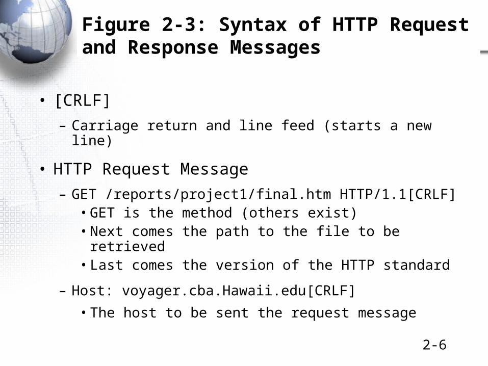
Figure 2-3: Syntax of HTTP Request and Response Messages
• [CRLF]
– Carriage return and line feed (starts a new line)
• HTTP Request Message
– GET /reports/project1/final.htm HTTP/1.1[CRLF]• GET is the method (others exist)• Next comes the path to the file to be retrieved• Last comes the version of the HTTP standard
– Host: voyager.cba.Hawaii.edu[CRLF]
• The host to be sent the request message

2-7
Figure 2-3: Syntax of HTTP Request and Response Messages, Continued
• HTTP Response Message– HTTP/1.1 200 OK[CRLF]
– Date: Tuesday, 20-JAN-2006 18:32:15 GMT[CRLF]
– Server: name of server software[CRLF]
– MIME-version: 1.0[CRLF]
– Content-type: text/plain[CRLF]
– [CRLF]
– File to be downloaded (byte stream)
• Syntax of fields (lines) after first line:– Keyword : Content [CRLF]
Syntax isvery rigid
2-8
• Test Your Understanding
• P 100

2-9
Figure 2-1: Standards Govern the Exchange of Messages, Continued
• General Message Syntax (Organization)
– General Message Organization (Figure 2-4)
– Primary parts of messages
• Data Field (content to be delivered)
• Header (everything before the data field)
• Trailer (everything after the data field)
– The header and trailer act like a delivery envelope for the data field.
HeaderData FieldTrailer

2-10
Figure 2-1: Standards Govern the Exchange of Messages, Continued
• General Message Syntax (Organization)– Header and trailer are further divided into fields
Trailer Data Field Header
OtherHeader
FieldDestination
AddressField is
Used by Switches and RoutersLike the Address on an Envelope
Message withall three parts

2-11
Figure 2-4: General Message Organization, Continued
Data Field Header
OtherHeader
Field
DestinationAddress
Field
Message withouta trailer
Usually only data linklayer messages have trailers

2-12
Figure 2-4: General Message Organization, Continued
Header
OtherHeader
Field
DestinationAddress
FieldMessage withonly a header
e.g.TCP supervisory messages are pure headers
(there is no data field content to deliver)

2-13
• Test Your Understanding
• P 100
2.Reliability

2-15
Figure 2-5: Reliable Transmission Control Protocol (TCP) Session
• The Transmission Control Protocol (TCP) is an important standard in Internet transmission
• TCP
– Receiver acknowledges each correctly-received TCP segment.
– If an acknowledgments is not received by the sender, the sender retransmits the TCP message (called a TCP segment)
– This gives reliability: error detection and error correction

2-16
TCP Segment (Message) 4Carries an HTTP Request
Segment 5 Acknowledges It
There Is No Need to Resend
Figure 2-5: Reliable TCP Session, Continued
Client PCTCP Process
WebserverTCP Process
4. Data = HTTP Request
5. ACK (4)
6. Data = HTTP Response
7. ACK (6)
CarryHTTPReq &Resp
(4)
Request-ResponseCycle for Data Transfer
2-17
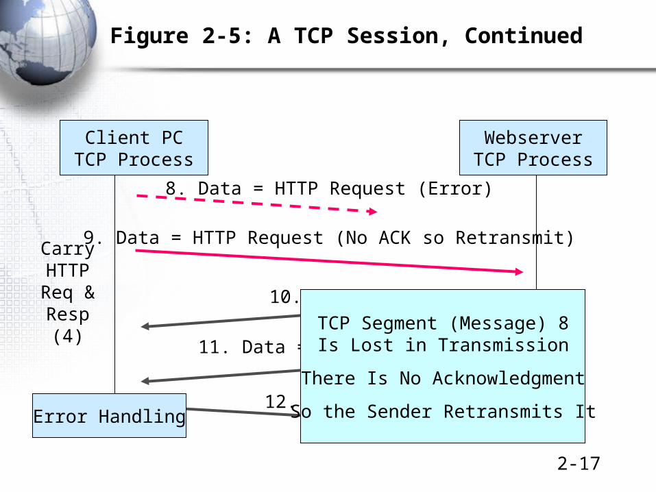
Figure 2-5: A TCP Session, Continued
Client PCTCP Process
WebserverTCP Process
CarryHTTPReq &Resp
(4)
8. Data = HTTP Request (Error)
9. Data = HTTP Request (No ACK so Retransmit)
10. ACK (9)
11. Data = HTTP Response
12. ACK (11)Error Handling
TCP Segment (Message) 8Is Lost in Transmission
There Is No Acknowledgment
So the Sender Retransmits It

2-18
• Test Your Understanding
• P 102

3.Connection-Oriented andConnectionless Protocols

2-20
Figure 2-6: Connection-Oriented and Connectionless Protocols
Message(No Sequence Number)
Connectionless Protocol
A B
Message 1 (Seq. Num = A1)
Message 2 (Seq. Num = A2)
Close Connection
Connection-Oriented Protocol
Open ConnectionA B
Message 3 (Seq. Num B1)
Connection-oriented protocols haveFormal openings and closings likeTelephone calls
Also have sequence numbersso that the receiver can putmessages in order
And so the receiver can sendAcknowledgments for specificmessages

2-21
Figure 2-6: Connection-Oriented and Connectionless Protocols, Continued
Client PCBrowser
WebserverApplication
HTTP Request
HTTP is connectionless
No OpeningsNo Closings
No Sequence NumbersNo Acknowledgments

2-22
Figure 2-6: Connection-Oriented and Connectionless Protocols, Continued
Client PCTCP Process
WebserverTCP Process
Connection-Opening Messages
Time
Connection-Closing Messages
Messages During the Connection
In TCP

2-23
Figure 2-7: Advantages and Disadvantages or Connection-Oriented Protocols
• Advantages
– Thanks to sequence numbers, the parties can tell if a message is lost.
– Error messages, such as ACKs can refer to specific messages.
– Long messages can be fragmented into many smaller messages that can fit inside packets.
• Fragmentation followed by reassembly on the destination host is an important concept in networking.

2-24
Figure 2-7: Advantages and Disadvantages or Connection-Oriented Protocols, Cont.
• Disadvantages
– The presence of many supervisory messages consumes existing bandwidth
– The processing of connection information places a heavy processing load on computers connected to the network

2-25
• Test Your Understanding
• P 105

4.The Hybrid TCP/IP-OSI Standards Architecture

2-27
Standards Architecture
• A Standards Architecture is a Broad Plan for Creating Standards
– Break the problem of effective communication into smaller pieces for ease of development
– Develop standards for the individual pieces
– Just as a building architect creating a general plan for a house before designing the individual rooms in detail
– The dominant architecture today is the hybrid TCP/IP-OSI standards architecture shown in the next slide

2-28
Figure 2-8: Hybrid TCP/IP-OSI Architecture
General Purpose(Core Later)
Layer Specific Layer Purpose
Application-application communication
Application (5) Application-application interworking
Transmission of a packet across an internet
Transport (4) Host-host communication
Internet (3) Packet delivery across an internet
Transmission of a frame across a single network (LAN or WAN)
Data Link (2) Frame delivery across a network
Physical (1) Device-device connection
2-29
Figure 2-8: Hybrid TCP/IP-OSI Architecture, Continued
• Physical and Data Link Layer Standards
– Govern Communication Through a Single Network
– LAN or WAN

2-30
Figure 2-9: Physical and Data Link Layer Standards in a Single Network
• Physical Layer
– Physical layer standards govern transmission between adjacent devices connected by a transmission medium
Switch X1
Physical LinkA-X1
Host A
Switch X2Physical LinkX1-X2

2-31
Figure 2-9: Physical and Data Link Layer Standards in a Single Network, Continued
• Data Link Layer
– Data link layer standards govern the transmission of frames across a single network—typically by sending them through several switches along the data link
Switch X1Host A
Switch X2
Host BData LinkA-B
Frame

2-32
Figure 2-9: Physical and Data Link Layer Standards in a Single Network, Continued
• Data Link Layer
– Data link layer standards also govern
• Frame organization
• Switch operation

2-33
Figure 2-9: Physical and Data Link Layer Standards in a Single Network, Continued
Host A
Mobile ClientStation
ServerStation
Switch
SwitchX2
Switch X1
Switch
Data LinkA-R1
Physical LinkA-X1
PhysicalLink
X1-X2
Router R1
PhysicalLink
X2-R1
3 Physical Links1 Data Link2 Switches

2-34
• Test Your Understanding
• P 107

2-35
Figure 2-10: Internet and Data Link Layers in an Internet
• Internet and Transport Layers
– An internet is a group of networks connected by routers so that any application on any host on any network can communicate with any application on any other host on any other network
– Internet and transport layer standards govern communication across an internet composed of two or more single networks
2-36
Figure 2-10: Internet and Data Link Layers in an Internet, Continued
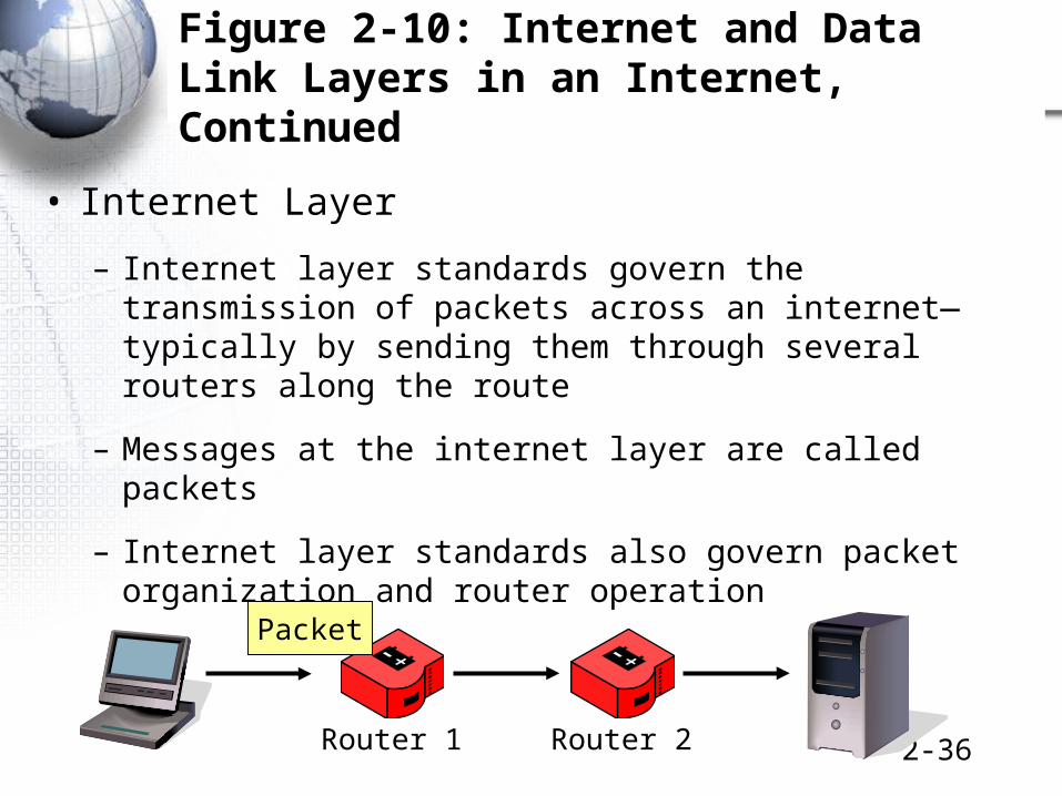
• Internet Layer
– Internet layer standards govern the transmission of packets across an internet—typically by sending them through several routers along the route
– Messages at the internet layer are called packets
– Internet layer standards also govern packet organization and router operation
Router 1 Router 2
Packet
2-37
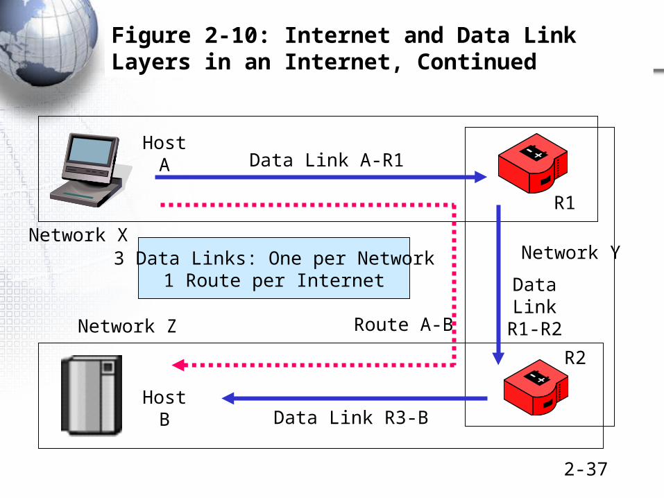
Figure 2-10: Internet and Data Link Layers in an Internet, Continued
Host B
Host A
Network XNetwork Y
Network Z
R1
R2
Data Link A-R1
Data Link R3-B
DataLink
R1-R2Route A-B
3 Data Links: One per Network1 Route per Internet

2-38
Figure 2-10: Internet and Data Link Layers in an Internet, Continued
Host A
Mobile ClientStation
ServerStation
Switch
SwitchX2
SwitchX1
Switch
Data LinkA-R1
Router R1
Packet
Frame X
Network X
RouteA-B
In Network X:Two Destination Addresses:
Packet: Host B (Destination Host)Frame: Router R1
2-39
Figure 2-10: Internet and Data Link Layers in an Internet, Continued
Router R1
Router R2
Packet
Frame Y
ToNetwork X
ToNetwork Z
Network Y
Data LinkR1-R2
RouteA-B
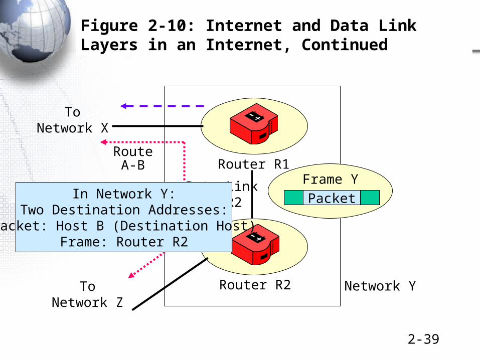
In Network Y:Two Destination Addresses:
Packet: Host B (Destination Host)Frame: Router R2

2-40
Figure 2-10: Internet and Data Link Layers in an Internet, Continued
Host B
Mobile ClientStations
SwitchZ1
SwitchX2
SwitchZ2
PacketFrame Z
Network Z
Router R2
Router
Data LinkR2-B
In Network Z:Two Destination Addresses:
Packet: Host B (Destination Host)Frame: Host B

2-41
Frames and Packets
• In an internet with hosts separated by N networks, there will be:
– 2 hosts
– One packet (going all the way between hosts)
– One route (between the two hosts)
– N frames (one in each network)
– There usually are many switches within single networks
– There usually are many physical links within networks

2-42
Figure 2-11: Internet and Transport Layer Standards
• Transport Layer
– Transport layer standards govern aspects of end-to-end communication between two end hosts that are not handled by the internet layer
– These standards allow hosts to work together even if the two computers are from different vendors and have different internal designs

2-43
Figure 2-11: Internet and Transport Layer Standards, Continued
2.Transport Layer
end-to-end (host-to-host)TCP is connection-oriented, reliable
UDP is connectionless and unreliable
1.Internet Layer
(usually IP)hop-by-hop (host-router or router-router)
connectionless, unreliable
Router 1 Router 2 Router 3
Client PCServer

2-44
• Test Your Understanding
• P 110
2-45
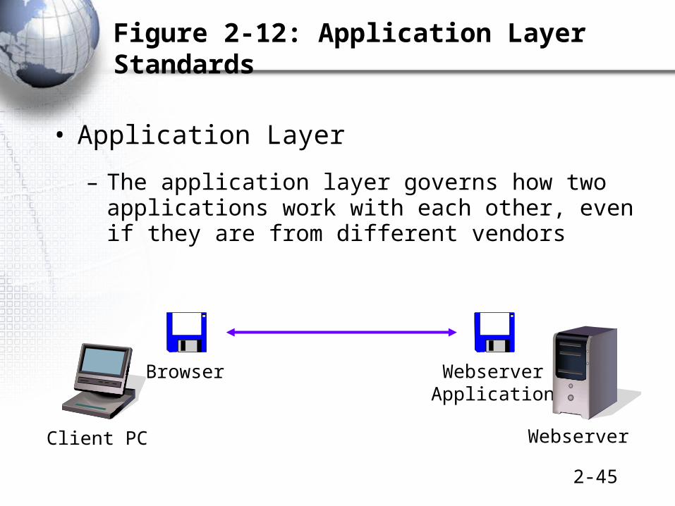
Figure 2-12: Application Layer Standards
• Application Layer
– The application layer governs how two applications work with each other, even if they are from different vendors
Webserver
Browser WebserverApplication
Client PC

2-46
Figure 2-12: Application Layer Standards
• There are more application layer standards than any other type of standard because there are many applications
– HTTP
– Database
– Instant Messaging
– FTP
– Etc.

2-47
• Test Your Understanding
• P 111

2-48
Standards Layers: Recap
• Application (5)
• Transport (4)
• Internet (3)
• Data Link (2)
• Physical (1)
Be able to repeatthis in your sleep!
Be able to repeatthis in your sleep!

2-49
• Why Layered Architectures?
• Page 111

5.Syntax Examples for Some Layer Messages

2-51
Octets
• Field length may be measured in octets
• An octet is a group of eight bits
• In computer science, an octet is called a byte
Octet = 8 Bits10010111

2-52
Figure 2-14: Ethernet Frame
Preamble (7 octets) 10101010 …
Start of Frame Delimiter(1 octet) 10101011
Destination Ethernet (MAC) Address (48 bits)
Source Ethernet (MAC) Address (48 bits)
Length (2 octets) Length of Data Field
Header
The Ethernet frame has 48-bit destination and source address fields.

2-53
Figure 2-14: Ethernet Frame, Continued
Data Field(variablelength)
PAD (added if data field < 46 octets)
Frame Check Sequence (32 bits)
LLC Subheader(usually 8 octets)
UsuallyIP Packet
EncapsulatedPacket
The Ethernet frame’s data field contains a IP packet(preceded by an LLC subheader).
PAD is added if the data field is less than 46 octets longPAD length is set to keep the data field plus PAD 46 octets
DataField

2-54
Figure 2-14: Ethernet Frame, Continued
• Sender computes the frame check sequence field value based on contents of other fields– Receiver recomputes the field value
• If the values match, there have been no errors
• If the values do not match, there has been an error– The receiver simply discards the frame
• Unreliable: error detection but not error correction
Frame Check Sequence (32 bits)

2-55
• Test Your Understanding
• P 115 12-15
2-56
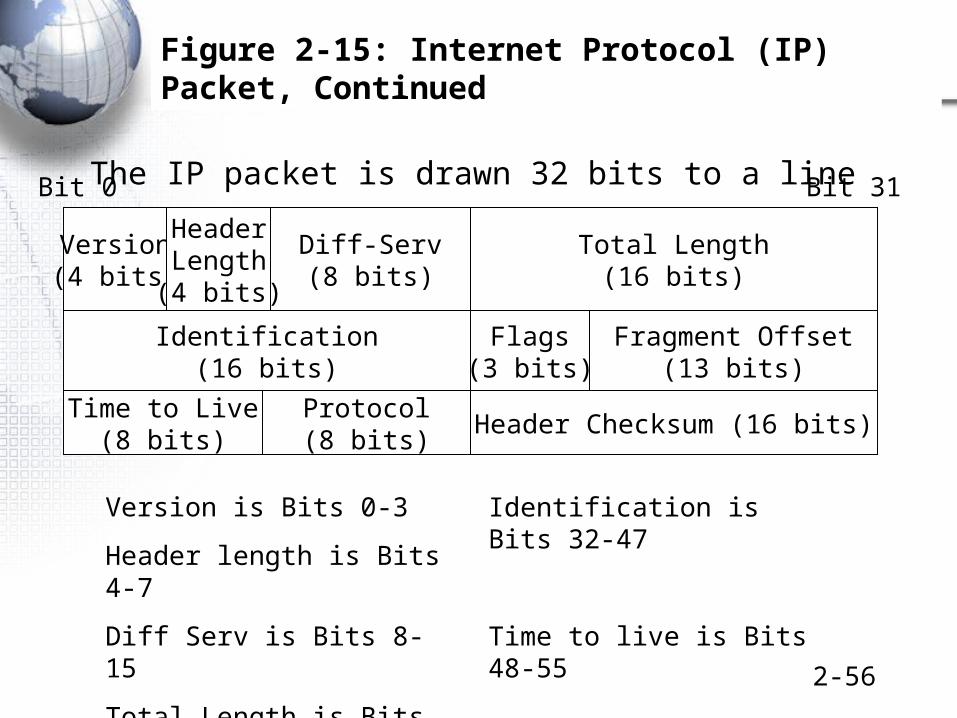
Figure 2-15: Internet Protocol (IP) Packet, Continued
Total Length(16 bits)
Version(4 bits)
Diff-Serv(8 bits)
HeaderLength(4 bits)
Identification(16 bits)
Flags(3 bits)
Fragment Offset(13 bits)
Header Checksum (16 bits)Protocol(8 bits)
Time to Live(8 bits)
Bit 0 Bit 31
Version is Bits 0-3
Header length is Bits 4-7
Diff Serv is Bits 8-15
Total Length is Bits 16-31
Identification is Bits 32-47
Time to live is Bits 48-55
The IP packet is drawn 32 bits to a line
2-57
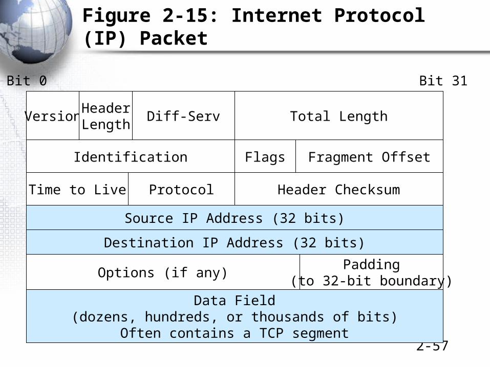
Figure 2-15: Internet Protocol (IP) Packet
Total LengthVersion Diff-ServHeaderLength
Source IP Address (32 bits)
Identification Flags Fragment Offset
Header ChecksumProtocolTime to Live
Bit 0 Bit 31
Destination IP Address (32 bits)
Options (if any)Padding
(to 32-bit boundary)
Data Field(dozens, hundreds, or thousands of bits)
Often contains a TCP segment

2-58
• Test Your Understanding
• P 116-117, 16-18

2-59
Figure 2-16: TCP and UDP at the Transport Layer
• TCP is reliable
• Not all applications need reliability
– Voice over IP cannot wait for lost or damaged packets to be transmitted
– Network management protocols need to place as low a burden on the network as possible
– Both types of applications use the simpler User Datagram Protocol (UDP) instead of TCP

2-60
Figure 2-16: TCP and UDP at the Transport Layer, Continued
Protocol TCP UDP
Layer Transport Transport
Connection-Oriented? Yes No
Reliable? Yes No
Burden on the two hosts High Low
Burden on the network High Low

2-61
Why Make TCP Reliable?
• Two reasons:
• 1. The transport layer only involves processing on the two hosts.
– Reliability is a heavy process.
– It would be far more expensive to make the internet or data link layer reliable because this would require complex processing on many routers or switches, respectively.
• 2. TCP’s reliability fixes errors at the transport layer and all lower layers in the process. This allows the transport layer to give the application clean data.

2-62
Figure 2-17: A Complex Application Protocol: The Simple Mail Transfer Protocol (SMTP)
• Some application protocols are simple
– HTTP: Simple request-response message cycle shown in Figure 2-2
• Some application protocols are complex (Figure 2-17)
– Simple Mail Transfer Protocol (SMTP) for e-mail
– More than a dozen messages must be exchanged to send an e-mail message

2-63
• Test Your Understanding
• P 119-121, 19-22

6.Vertical Communication Between Layer Processes on the Same Host

2-65
Figure 2-18: Layered Communication on the Source Host
ApplicationProcess
HTTPMessage
TransportProcess
HTTPMessage
TCPHdr
Encapsulation of HTTP Messagein Data Field of TCP Segment
Passes MessageDown to Transport Process
The process begins when a browser creates an HTTP request message

2-66
Figure 2-18: Layered Communication on the Source Host, Continued
• When a layer process (N) creates a message, it passes it down to the next-lower-layer process (N-1) immediately
• The receiving process (N-1) will encapsulate the Layer N message, that is, place it in the data field of its own (N-1) message

2-67
Figure 2-18: Layered Communication on the Source Host, Continued
TransportProcess
HTTPMessage
InternetProcess
HTTPMessage
TCPHdr
TCPHdr
IPHdr
Encapsulation of TCP Segmentin Data Field of IP Packet

2-68
Figure 2-18: Layered Communication on the Source Host, Continued
InternetProcess
HTTPMessage
TCPHdr
IPHdr
Data LinkProcess
HTTPMessage
TCPHdr
IPHdr
EthHdr
EthTrlr
Encapsulation of IP Packetin Data Field of Ethernet Frame

2-69
Figure 2-18: Layered Communication on the Source Host, Continued
Data LinkProcess
HTTPMessage
TCPHdr
IPHdr
EthHdr
EthTrlr
Physical Process
Physical Layer converts the bits of the frame into signals.

2-70
Figure 2-18: Layered Communication on the Source Host, Continued
The following is the final frame for aan HTTP message on an Ethernet LAN
HTTPMessage
TCPHdr
IPHdr
EthHdr
EthTrlr
L5 L4 L3 L2L2
Notice the Pattern: From Right to Left: L2, L3, L4, L5, maybe L2
Start with the highest-layer message (in this case, 5)
Add headers for each lower layer (L4, L3, and L2, in this case)
Don’t forget the possible trailing L2 trailer

2-71
• Test Your Understanding
• P 124 23
2-72
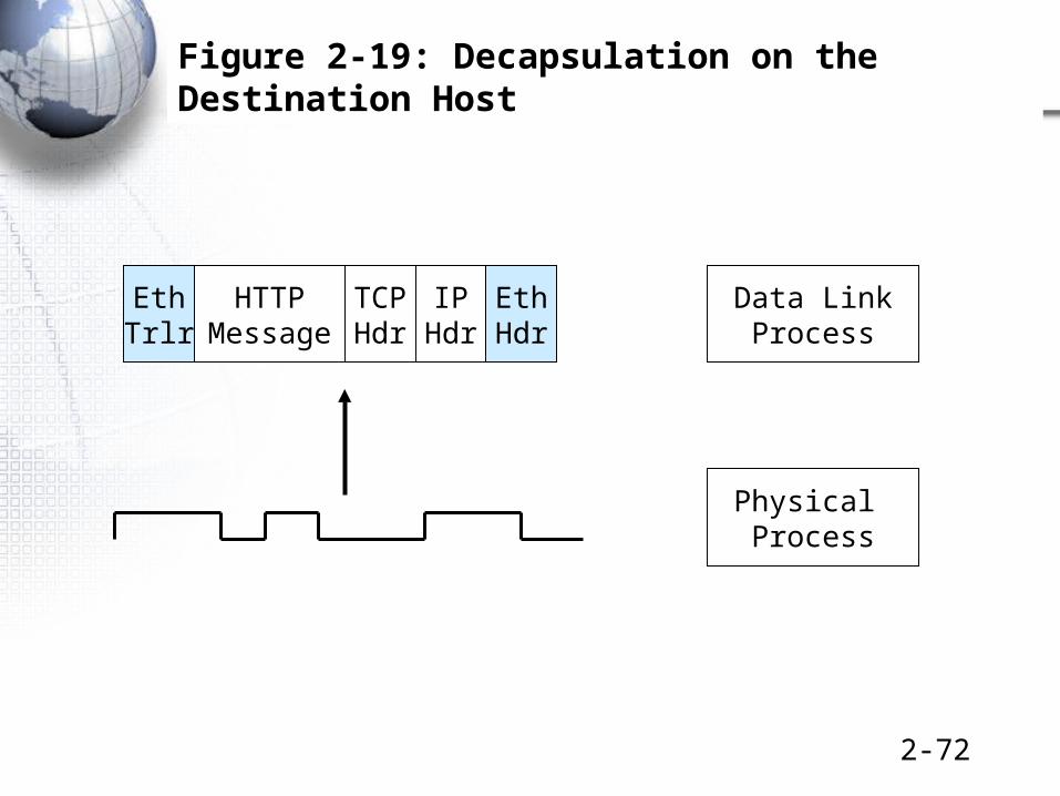
Figure 2-19: Decapsulation on the Destination Host
HTTPMessage
TCPHdr
IPHdr
EthHdr
EthTrlr
Data LinkProcess
Physical Process
2-73
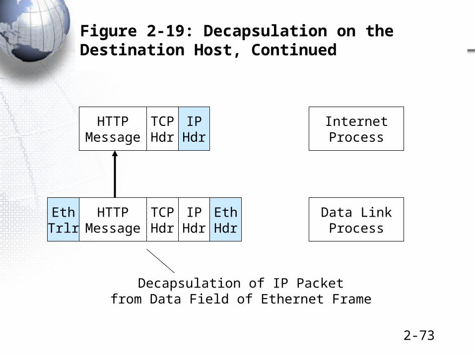
Figure 2-19: Decapsulation on the Destination Host, Continued
HTTPMessage
TCPHdr
IPHdr
EthHdr
EthTrlr
Data LinkProcess
InternetProcess
HTTPMessage
TCPHdr
IPHdr
Decapsulation of IP Packetfrom Data Field of Ethernet Frame

2-74
Figure 2-19: Decapsulation on the Destination Host, Continued
InternetProcess
HTTPMessage
TCPHdr
IPHdr
TransportProcess
HTTPMessage
TCPHdr
Decapsulation of TCP Segmentfrom Data Field of IP Packet

2-75
Figure 2-19: Decapsulation on the Destination Host, Continued
TransportProcess
HTTPMessage
TCPHdr
ApplicationProcess
HTTPMessage
Decapsulation of HTTP Messagefrom Data Field of TCP Segment

2-76
• Test Your Understanding
• P 126 24
2-77
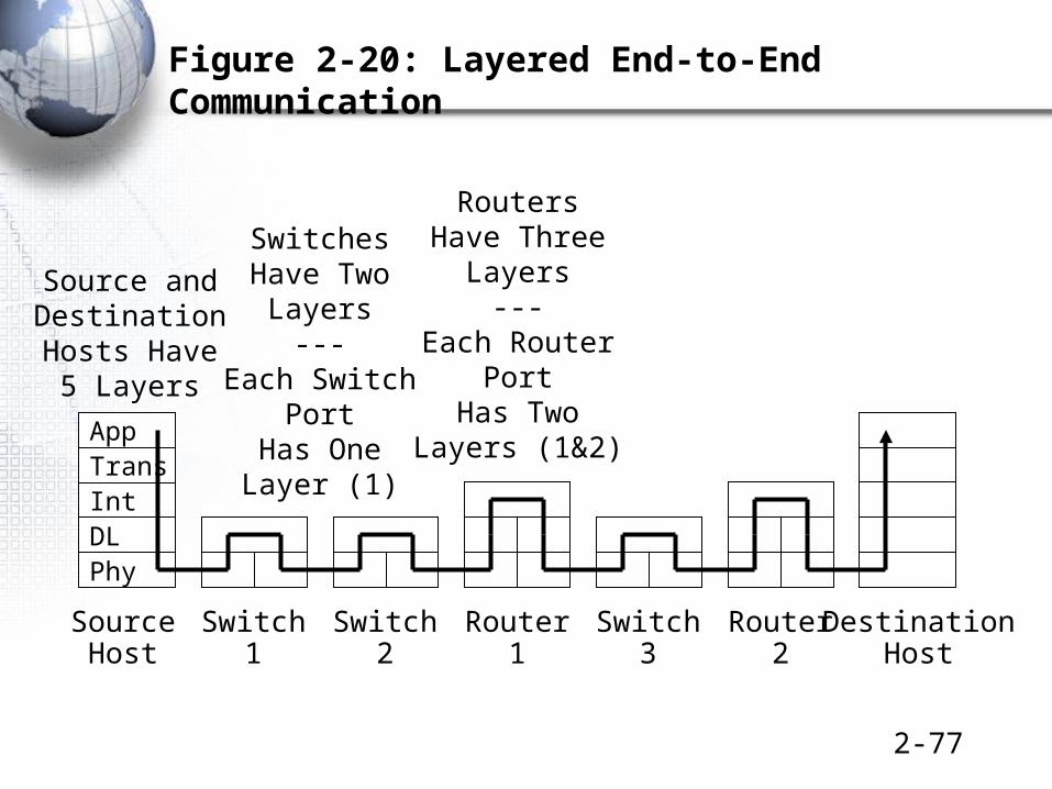
Figure 2-20: Layered End-to-End Communication
Int
App
DL
Trans
Phy
SourceHost
DestinationHost
Switch1
Switch2
Router1
Switch3
Router2
Source andDestinationHosts Have
5 Layers
SwitchesHave Two
Layers---
Each SwitchPort
Has OneLayer (1)
RoutersHave Three
Layers---
Each RouterPort
Has TwoLayers (1&2)

2-78
Figure 2-21: Combining Horizontal and Vertical Communication
Int
App
DL
Trans
Phy
SourceHost
DestinationHost
Switch1
Switch2
Router1
Switch3
Router2
Hypertext Transfer Protocol
Transmission Control Protocol
Internet Protocol
2-79
• Test Your Understanding
• P 127 25-26

7.OSI, TCP/IP, and Other Standards Architectures

2-81
Figure 2-22: The Hybrid TCP/IP-OSI Architecture
TCP/IPOSIHybrid TCP/IP-OSIBroad Purpose
Application
Application
Presentation
Session
Application(Layer 5)
Communicationbetweenapplications
Transport
Internet
Transport
Network
Transport (Layer 4)
Internet (Layer 3)Internetworking
Use OSI Standards Here
Data Link
Physical
Data Link (Layer 2)
Physical (Layer 1)
Transmissionwithin a singleLAN or WAN

2-82
Figure 2-23: OSI and TCP/IP
OSI TCP/IP
StandardsAgency or Agencies
ISO (InternationalOrganization for Standardization)
ITU-T (InternationalTelecommunicationsUnion—TelecommunicationsStandards Sector)
IETF (InternetEngineering TaskForce)

2-83
Figure 2-23: OSI and TCP/IP, Continued
OSI TCP/IP
Dominance Nearly 100% dominant at physical and datalink layers
70%-80% dominantat the internet and transportlayers.
Documents areCalled
Various Mostly RFCs (requestsfor comments)

2-84
Figure 2-24: OSI Layers
• Layer 1: OSI Physical Layer Standards
– Nearly always used in the hybrid TCP/IP-OSI architecture
• Layer 2: OSI Data Link Layer Standards
– Nearly always used in the hybrid TCP/IP-OSI architecture

2-85
Figure 2-24: OSI Layers, Continued
• Layer 3: OSI Network Layer Standards– Same function as internet layer standards in TCP/IP
– But OSI network layer standards are incompatible with TCP/IP internet layer standards
– Rarely used
• Layer 4: OSI Transport Layer Standards– Same function as transport layer in TCP/IP
– But OSI transport layer standards are incompatible with TCP/IP transport layer standards
– Rarely used

2-86
Figure 2-24: OSI Layers, Continued
• Layer 5: OSI Session Layer Standards
– Initiate and maintain a connection between application programs on different computers
– Nothing like this layer in TCP/IP
– Rarely used because OSI is rarely used above the data link layer and below the application layer

2-87
Figure 2-24: OSI Layers, Continued
• Layer 6: OSI Presentation Layer Standards
– Designed to handle data formatting differences between the computers, data compression, and encryption.
• Rarely used this way because OSI standards are rarely used above the data link layer and below the application layer
– In practice, a category for general OSI file format standards used in multiple applications
• JPEG, etc.
• These standards are widely used

2-88
Figure 2-24: OSI Layers, Continued
• Layer 7: OSI Application Layer
– For other application-specific matters
– Some OSI application layer standards are used
• Run over TCP/IP transport/internet layer processes
• Almost always without actual session and presentation layer processes
2-89
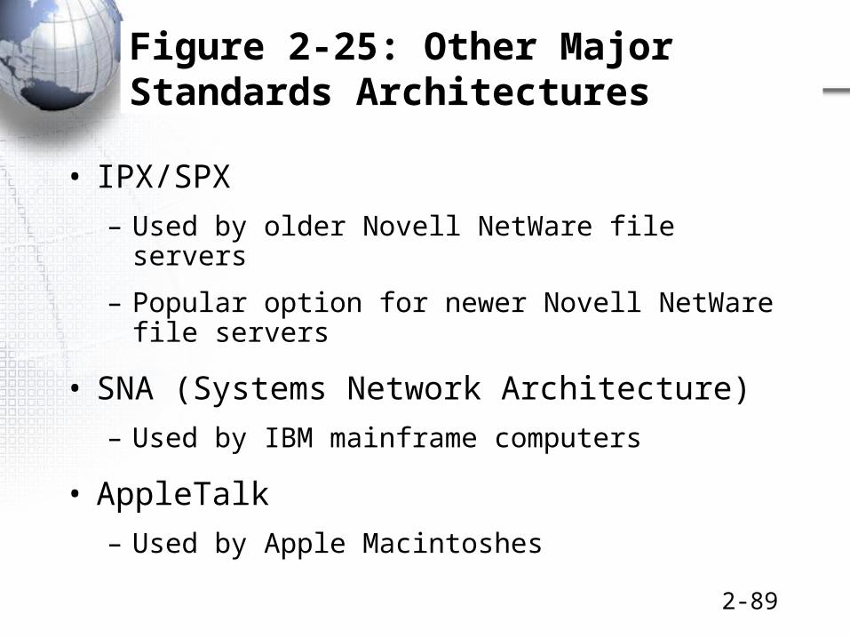
Figure 2-25: Other Major Standards Architectures
• IPX/SPX
– Used by older Novell NetWare file servers
– Popular option for newer Novell NetWare file servers
• SNA (Systems Network Architecture)
– Used by IBM mainframe computers
• AppleTalk
– Used by Apple Macintoshes
2-90
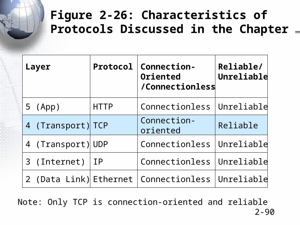
Figure 2-26: Characteristics of Protocols Discussed in the Chapter
Layer Protocol Connection-Oriented/Connectionless
Reliable/Unreliable
5 (App) HTTP Connectionless Unreliable
4 (Transport) TCPConnection-oriented
Reliable
3 (Internet) IP Connectionless Unreliable
2 (Data Link) Ethernet Connectionless Unreliable
Note: Only TCP is connection-oriented and reliable
4 (Transport) UDP Connectionless Unreliable

2-91
• Case study
• Chp 1 a page 42
• Chp 1c page 77

8.Topics Covered

2-93
Topics Covered
• Standards govern the semantics and syntax of messages
– HTTP: Text request and response messages
– Data field, header, and trailer
– Header and trailer subdivided into fields
• Reliability
– In TCP, receiver sends ACKs
– Senders retransmit non-acknowledged segments

2-94
Topics Covered
• Connection-oriented versus connectionless
– TCP is connection-oriented
– HTTP is connectionless
• Hybrid TCP/IP-OSI Architecture
– OSI is nearly 100% dominant at Layers 1 and 2
– TCP/IP is 70% to 80% dominant at Layers 3 and 4
– Situation at Layer 5 is complex
2-95
Topics Covered
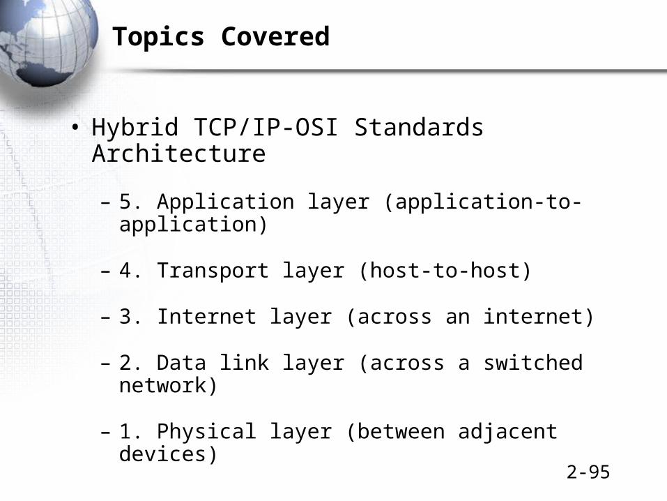
• Hybrid TCP/IP-OSI Standards Architecture
– 5. Application layer (application-to-application)
– 4. Transport layer (host-to-host)
– 3. Internet layer (across an internet)
– 2. Data link layer (across a switched network)
– 1. Physical layer (between adjacent devices)

2-96
Topics Covered
• Ethernet
– Source and destination addresses are 48 bits long
– Switches forward packets by destination addresses
– Data field encapsulates an IP packet
– Unreliable: if detects an error, drops the frame
• Internet Protocol (IP)
– 32-bit addresses
– Show 32 bits on each line
– Unreliable: checks headers for errors but discards
2-97
Topics Covered
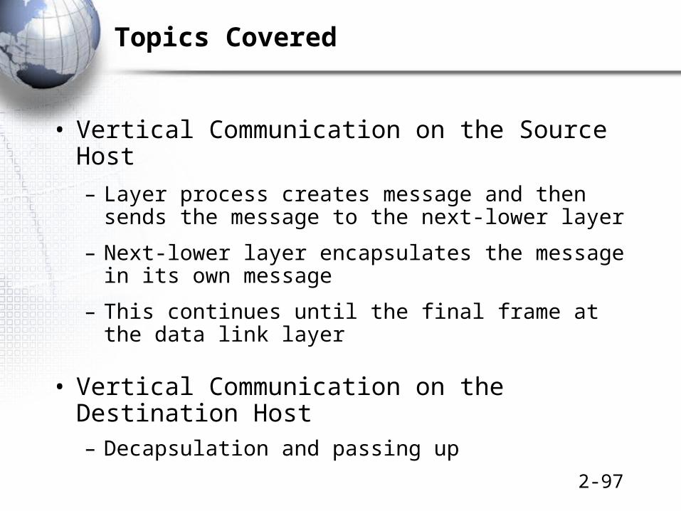
• Vertical Communication on the Source Host
– Layer process creates message and then sends the message to the next-lower layer
– Next-lower layer encapsulates the message in its own message
– This continues until the final frame at the data link layer
• Vertical Communication on the Destination Host– Decapsulation and passing up

2-98
Topics Covered
• Not All Devices Have All Layers
– Hosts have all five
– Routers have only the lowest three
– Switches have only the lowest two

2-99
Topics Covered
• OSI Architecture– Divides application layer into three layers
• Session• Presentation• Application
• Other Standards Architectures– IPX/SPX
– SNA
– AppleTalk

2-100
标准化组织1 . ISO ( International Standards Organization ),国际标准化组织,
为大量科目制定标准;
2 . ITU ( International Telecommunication Union ),国际电信联盟,主要有三个部门:无线通信部门、电信标准化部门、开发部门。任务是制定电话、电报和数据通信接口的技术建议。
3 . IEEE ( Institute of Electrical and Electronics Engineers ),电气和电子工程师协会,是世界最大的电类专业组织。
4 . NIST ( National Institute of Standards and Technology ),美国标准和技术协会,是美国商业部的一个办事机构,制定美国政府购买物品的强制标准。
5 . IAB ( Internet Activities Board ),因特网活动委员会
6 . IAB ( Internet Architecture Board ),因特网体系结构委员会

2-101
关于因特网的标准化工作
因特网协会 ISOC
因特网研究指导小组IRSG
因特网研究部 IRTF 因特网工程部 IETF
因特网工程指导小组IESG
…
RG WG… …RG…
领域 领域
因特网体系结构研究委员会 IAB
WGWGWG

2-102
制订因特网的正式标准要经过以下的四个阶段
• 因特网草案 (Internet Draft) —— 在这个阶段还不是 RFC 文档。
• 建议标准 (Proposed Standard) —— 从这个阶段开始就成为 RFC 文档。
• 草案标准 (Draft Standard)
• 因特网标准 (Internet Standard)

2-103
各种 RFC 之间的关系
因特网草案
建议标准
草案标准
因特网标准
历史的 RFC
实验的 RFC 提供信息的 RFC
6 种 RFC


