Network Standard - Ausgrid...is for reference by field, technical and engineering staff. Ausgrid...
31
NW000-S0096 UNCONTROLLED IF PRINTED Page 1 of 31 Network Standard NETWORK Document No Amendment No Approved By Approval Date Review Date : : : : : NW000-S0096 3 Manager – T & DME 20/11/2018 14/07/2020 (Supersedes Network Standard (Network) NW000-S0096. Amendment No.2 NW000-S0096 NS161 SPECIFICATION FOR TESTING OF UNDERGROUND CABLES
Transcript of Network Standard - Ausgrid...is for reference by field, technical and engineering staff. Ausgrid...
NW000-S0096 UNCONTROLLED IF PRINTED Page 1 of 31
Network Standard
NETWORK
Document No Amendment No Approved By Approval Date Review Date
:::::
NW000-S0096 3 Manager – T & DME 20/11/2018 14/07/2020
(Supersedes Network Standard (Network) NW000-S0096. Amendment No.2
NW000-S0096 NS161 SPECIFICATION FOR TESTING OF UNDERGROUND CABLES

NS161 Specification for Testing of Underground Cables Amendment No 3
NW000-S0096 UNCONTROLLED IF PRINTED Page 2 of 31
ISSUE
For issue to all Ausgrid and Accredited Service Providers’ staff involved with commissioning and testing of underground cables, and is for reference by field, technical and engineering staff.
Ausgrid maintains a copy of this and other Network Standards together with updates and amendments on www.ausgrid.com.au.
Where this standard is issued as a controlled document replacing an earlier edition, remove and destroy the superseded document.
DISCLAIMER
As Ausgrid’s standards are subject to ongoing review, the information contained in this document may be amended by Ausgrid at any time. It is possible that conflict may exist between standard documents. In this event, the most recent standard shall prevail.
This document has been developed using information available from field and other sources and is suitable for most situations encountered in Ausgrid. Particular conditions, projects or localities may require special or different practices. It is the responsibility of the local manager, supervisor, assured quality contractor and the individuals involved to make sure that a safe system of work is employed and that statutory requirements are met.
Ausgrid disclaims any and all liability to any person or persons for any procedure, process or any other thing done or not done, as a result of this Standard.
All design work, and the associated supply of materials and equipment, must be undertaken in accordance with and consideration of relevant legislative and regulatory requirements, latest revision of Ausgrid’s Network Standards and specifications and Australian Standards. Designs submitted shall be declared as fit for purpose. Where the designer wishes to include a variation to a network standard or an alternative material or equipment to that currently approved the designer must obtain authorisation from the Network Standard owner before incorporating a variation to a Network Standard in a design.
External designers including those authorised as Accredited Service Providers will seek approval through the approved process as outlined in NS181 Approval of Materials and Equipment and Network Standard Variations. Seeking approval will ensure Network Standards are appropriately updated and that a consistent interpretation of the legislative framework is employed.
Notes: 1. Compliance with this Network Standard does not automatically satisfy the requirements of a Designer Safety Report. The designer must comply with the provisions of the Workplace Health and Safety Regulation 2011 (NSW - Part 6.2 Duties of designer of structure and person who commissions construction work) which requires the designer to provide a written safety report to the person who commissioned the design. This report must be provided to Ausgrid in all instances, including where the design was commissioned by or on behalf of a person who proposes to connect premises to Ausgrid’s network, and will form part of the Designer Safety Report which must also be presented to Ausgrid. Further information is provided in Network Standard (NS) 212 Integrated Support Requirements for Ausgrid Network Assets.
2. Where the procedural requirements of this document conflict with contestable project procedures, the contestable project procedures shall take precedent for the whole project or part thereof which is classified as contestable. Any external contact with Ausgrid for contestable works projects is to be made via the Ausgrid officer responsible for facilitating the contestable project. The Contestable Ausgrid officer will liaise with Ausgrid internal departments and specialists as necessary to fulfil the requirements of this standard. All other technical aspects of this document which are not procedural in nature shall apply to contestable works projects.
INTERPRETATION
In the event that any user of this Standard considers that any of its provisions is uncertain, ambiguous or otherwise in need of interpretation, the user should request Ausgrid to clarify the provision. Ausgrid’s interpretation shall then apply as though it was included in the Standard, and is final and binding. No correspondence will be entered into with any person disputing the meaning of the provision published in the Standard or the accuracy of Ausgrid’s interpretation.
KEYPOINTS
This standard has a summary of content labelled “KEYPOINTS FOR THIS STANDARD”. The inclusion or omission of items in this summary does not signify any specific importance or criticality to the items described. It is meant to simply provide the reader with a quick assessment of some of the major issues addressed by the standard. To fully appreciate the content and the requirements of the standard it must be read in its entirety.
AMENDMENTS TO THIS STANDARD
Where there are changes to this standard from the previously approved version, any previous shading is removed and the newly affected paragraphs are shaded with a grey background. Where the document changes exceed 25% of the document content, any grey background in the document is to be removed and the following words should be shown below the title block on the right hand side of the page in bold and italic, for example, Supersedes – document details (for example, “Supersedes Document Type (Category) Document No. Amendment No.”).
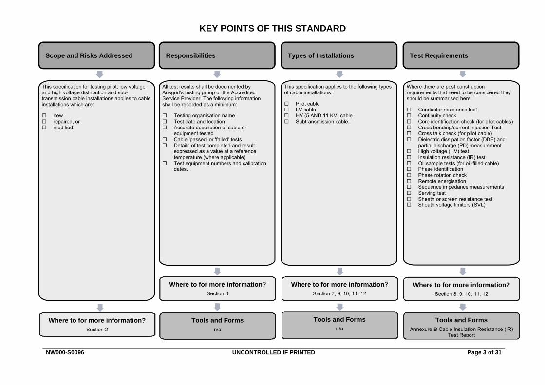
KEY POINTS OF THIS STANDARD
NW000-S0096 UNCONTROLLED IF PRINTED Page 3 of 31
Responsibilities Types of Installations Test Requirements Scope and Risks Addressed
Tools and Forms n/a
Tools and Forms Annexure B Cable Insulation Resistance (IR)
Test Report
This specification for testing pilot, low voltage and high voltage distribution and sub-transmission cable installations applies to cable installations which are:
new repaired, or modified.
Where to for more information? Section 2
All test results shall be documented by Ausgrid’s testing group or the Accredited Service Provider. The following information shall be recorded as a minimum:
Testing organisation name Test date and location Accurate description of cable or
equipment tested Cable 'passed' or 'failed' tests Details of test completed and result
expressed as a value at a reference temperature (where applicable)
Test equipment numbers and calibration dates.
This specification applies to the following types of cable installations :
Pilot cable LV cable HV (5 AND 11 KV) cable Subtransmission cable.
Where there are post construction requirements that need to be considered they should be summarised here.
Conductor resistance test Continuity check Core identification check (for pilot cables) Cross bonding/current injection Test Cross talk check (for pilot cable) Dielectric dissipation factor (DDF) and
partial discharge (PD) measurement High voltage (HV) test Insulation resistance (IR) test Oil sample tests (for oil-filled cable) Phase identification Phase rotation check Remote energisation Sequence impedance measurements Serving test Sheath or screen resistance test Sheath voltage limiters (SVL)
Tools and Forms n/a
Where to for more information? Section 6
Where to for more information? Section 7, 9, 10, 11, 12
Where to for more information? Section 8, 9, 10, 11, 12

NS161 Specification for Testing of Underground Cables Amendment No 3
NW000-S0096 UNCONTROLLED IF PRINTED Page 4 of 31
Network Standard NS161
Specification for Testing of Underground Cables
Contents
PURPOSE ............................................................................................................................................. 6 1.0
SCOPE .................................................................................................................................................. 6 2.0
REFERENCES ...................................................................................................................................... 6 3.0 General ...................................................................................................................................... 6 3.1 Ausgrid documents .................................................................................................................... 6 3.2 Other standards and documents ................................................................................................ 7 3.3 Acts and regulations................................................................................................................... 7 3.4
DEFINITIONS ........................................................................................................................................ 7 4.0
INTRODUCTION ................................................................................................................................... 9 5.0
RESPONSIBILITIES .............................................................................................................................. 9 6.0
TYPES OF INSTALLATIONS .............................................................................................................. 10 7.0 New installations ...................................................................................................................... 10 7.1 Repaired installations - maintenance or repairs after failure or damage ................................. 10 7.2 Modified installations - system modifications ........................................................................... 10 7.3
GENERAL TEST REQUIREMENTS ................................................................................................... 10 8.0 General .................................................................................................................................... 10 8.1 Conductor resistance test ........................................................................................................ 10 8.2 Continuity check ....................................................................................................................... 10 8.3 Core identification check (for pilot cables) ............................................................................... 10 8.4 Cross bonding/current injection test ......................................................................................... 11 8.5 Cross talk check (for pilot cable) .............................................................................................. 11 8.6 Dielectric dissipation factor (DDF) and partial discharge (PD) measurement ......................... 11 8.7 High voltage (HV) test .............................................................................................................. 12 8.8 Insulation resistance (IR) test .................................................................................................. 12 8.9 Phase identification .................................................................................................................. 13 8.10 Phase rotation check................................................................................................................ 13 8.11 Remote energisation ................................................................................................................ 13 8.12
Remote energisation precautions ................................................................................ 13 8.12.1 Cable installation .......................................................................................................... 13 8.12.2 When remote energisation shall not replace the high voltage test .............................. 14 8.12.3
Sequence impedance measurements ..................................................................................... 14 8.13 Serving Test ............................................................................................................................. 14 8.14
Sub-transmission cables .............................................................................................. 14 8.14.1 High voltage cables ...................................................................................................... 14 8.14.2
Sheath or screen resistance test ............................................................................................. 14 8.15 Sheath voltage limiters (SVL) .................................................................................................. 14 8.16
PILOT CABLE INSTALLATIONS ......................................................................................................... 15 9.0 Requirements ........................................................................................................................... 15 9.1 Required tests .......................................................................................................................... 15 9.2 Continuity and core identification ............................................................................................. 16 9.3
NS161 Specification for Testing of Underground Cables Amendment No 3
NW000-S0096 UNCONTROLLED IF PRINTED Page 5 of 31
Requirements ............................................................................................................... 16 9.3.1 IR Tests ........................................................................................................................ 16 9.3.2
Sub-transmission general tests ................................................................................................ 16 9.4 Requirements ............................................................................................................... 16 9.4.1 High voltage tests ......................................................................................................... 16 9.4.2
LV CABLE INSTALLATIONS ............................................................................................................... 17 10.0 Requirements ........................................................................................................................... 17 10.1 Required tests .......................................................................................................................... 17 10.2 IR tests ..................................................................................................................................... 17 10.3 General tests ............................................................................................................................ 17 10.4
HV (5 AND 11 KV) CABLE INSTALLATIONS ..................................................................................... 18 11.0 Requirements ........................................................................................................................... 18 11.1 Required tests .......................................................................................................................... 18 11.2 IR tests ..................................................................................................................................... 18 11.3
Requirements ............................................................................................................... 18 11.3.1 IR test exceptions ......................................................................................................... 19 11.3.2
High voltage tests ..................................................................................................................... 19 11.4 Voltage uprating of cable installations ..................................................................................... 20 11.5
SUB-TRANSMISSION CABLE INSTALLATIONS ............................................................................... 21 12.0 Requirements ........................................................................................................................... 21 12.1 Required tests .......................................................................................................................... 21 12.2 IR tests ..................................................................................................................................... 22 12.3 Serving tests ............................................................................................................................ 22 12.4 High voltage tests ..................................................................................................................... 23 12.5 General tests ............................................................................................................................ 23 12.6
OIL SAMPLE TESTING REQUIREMENTS ......................................................................................... 25 13.0 General .................................................................................................................................... 25 13.1 Sampling Requirements ........................................................................................................... 25 13.2 Test Requirements ................................................................................................................... 26 13.3 Reports & Recording ................................................................................................................ 26 13.4
RECORDKEEPING ............................................................................................................................. 27 14.0
AUTHORITIES AND RESPONSIBILITIES .......................................................................................... 27 15.0
DOCUMENT CONTROL...................................................................................................................... 27 16.0
ANNEXURE A – TESTING OF SELECTED 132KV CABLE CIRCUITS ......................................................... 28
ANNEXURE B - SAMPLE IR TEST REPORT ................................................................................................ 29
ANNEXURE C – COMPLIANCE CHECKLIST ................................................................................................ 30
NS161 Specification for Testing of Underground Cables Amendment No 3
NW000-S0096 UNCONTROLLED IF PRINTED Page 6 of 31
PURPOSE 1.0
This document is Ausgrid’s specification for testing pilot, low voltage and high voltage distribution and sub-transmission cable installations. The purpose of performing cable tests is to prove the circuit is safe to energise or commission.
SCOPE 2.0
This specification applies to cable installations which are new, repaired or modified.
REFERENCES 3.0
General 3.1All work covered in this document must conform to all relevant Legislation, Standards, Codes of Practice and Network Standards. Current Network Standards are available on Ausgrid’s Internet site at www.ausgrid.com.au.
Ausgrid documents 3.2 Company Form (Governance) - Network Document Endorsement and Approval Company Procedure (Governance) - Network Document Endorsement and Approval Company Procedure (Network) - Production / Review of Network Standards Customer Installation Safety Plan Electrical Safety Rules Electricity Network Safety Management System Manual ES 4 Accredited Service Provider Authorisation NS129 11kV Joints and Terminations - Paper Insulated Lead Covered Cables NS130 Specification for Laying of Underground Cables Up to and including 11kV NS156 Working Near or Around Underground Cables NS168 Specification for the Design & Construction of 33kV, 66kV & 132kV Underground
Cables NS177 11kV Joints (including Transition Joints) and Terminations - Polymeric Insulated Cables NS181 Approval of Materials and Equipment and Network Standard Variations NS212 Integrated Support Requirements for Ausgrid Network Assets NS261 Requirement for Design Compliance Framework for Network Standards

NS161 Specification for Testing of Underground Cables Amendment No 3
NW000-S0096 UNCONTROLLED IF PRINTED Page 7 of 31
Other standards and documents 3.3 AS/NZS 1026 - Electric cables - Impregnated paper insulated – For working voltages up to and
including 19/33 (36)kV. AS/NZS 1429.1 - Electric cables - Polymeric insulated - For working voltages 1.9/3.3 (3.6)kV
up to and including 19/33 (36)kV. AS/NZS 1429.2 - Electric cables - Polymeric insulated - For working voltages 19/33 (36)kV up
to and including 87/150 (170)kV. AS/NZS 1931.2 – High-voltage test techniques - Measuring systems. AS/NZS 60840 Power cables with extruded insulation and their accessories for rated voltages
above 30kV (Um = 36kV) up to 150kV (Um = 170kV) Test methods and requirements ENA D(b)31 Guide for the Maintenance of High Voltage Paper/Oil Insulated Cables and
Accessories, Energy Networks Association formerly the Electricity Supply Association of Australia.
ENA Doc 001-2008 National Electricity Network Safety Code IEC 60141 – 1 Tests on Oil Filled and Gas-Pressure Cable and their Accessories IEC 60502 – 2 Power cables with extruded insulation and their accessories for rated voltages
from 1kV up to 30kV - Part 2: Cables for rated voltages from 6kV up to 30kV. IEC 60229 Tests on cable oversheaths which have a special protective function and are
applied by extrusion. IEEE P400.2/D5 Guide for Field Testing of Shielded Power Cable Systems Using Very Low
Frequency (VLF).
Acts and regulations 3.4 Electricity Supply (General) Regulation 2014 (NSW) Electricity Supply (Safety and Network Management) Regulation 2014 Work Health and Safety Act 2011 and Regulation 2011
DEFINITIONS 4.0
Accredited Service Provider (ASP)
An individual or entity accredited by the NSW Department of Industry, Division of Resources and Energy, in accordance with the Electricity Supply (Safety and Network Management) Regulation 2014 (NSW).
Ausgrid's Representative
A person appointed by Ausgrid to act as a liaison person between the Client and Ausgrid, and who has responsibility for ensuring that all works which are of interest to Ausgrid are carried out in accordance with Ausgrid's requirements.
Business Management System (BMS)
An Ausgrid internal integrated policy and procedure framework that contains the approved version of documents.
Client A Client is an individual or an entity who has responsibility for the design and construction of the electricity reticulation installation, and who enters into an agreement/contractual arrangement with accredited personnel and/or Ausgrid for developing the installation. A client could be a developer, Service Provider or customer.
Cable Installation
A continuous length of installed cable including joints and terminations, but not including switches.
Document control
Ausgrid employees who work with printed copies of document must check the BMS regularly to monitor version control. Documents are considered “UNCONTROLLED IF PRINTED”, as indicated in the footer.
EPR type cable Ethylene Propylene Rubber insulated cable, generally 11kV single or multicore cable.
Fluid Filled type Paper insulated cable, pressurised with low viscosity insulating fluid from
NS161 Specification for Testing of Underground Cables Amendment No 3
NW000-S0096 UNCONTROLLED IF PRINTED Page 8 of 31
cable feed tanks, generally 33kV three core and 132kV single core cables.
Gas Pressure (GP) type cable
Paper insulated cable, pressurised with dry nitrogen from cylinders via regulators (typically at 1400 kPa), generally 33kV three core cable.
High Voltage (HV) Installation
An installation where the nominal phase-to-phase voltage is greater than 1000 V and less than 33kV.
IR Insulation Resistance
IRT Insulation Resistance Tester ('megger' or similar)
Low Voltage (LV) Installation
An installation where the nominal phase-to-phase voltage is less than or equal to 1000 V
Network Standard
A document, including Network Planning Standards, that describes the Company's minimum requirements for planning, design, construction, maintenance, technical specification, environmental, property and metering activities on the distribution and transmission network. These documents are stored in the Network Category of the BMS repository
Phase Identification
Phase identification is a test to identify the same phase conductors of a cable at both ends of the cable.
Phasing Phasing is a test to prove that energised conductors on each side of a switch or open point can be safely joined together by closing the switch or open point
PILC type cable Paper Insulated Lead Covered cable, generally 11kV - 33kV three core cables.
Network Standard
A document, including Network Planning Standards, that describes the Company's minimum requirements for planning, design, construction, maintenance, technical specification, environmental, property and metering activities on the distribution and transmission network. These documents are stored in the Network Category of the BMS repository.
Review date The review date displayed in the header of the document is the future date for review of a document. The default period is three years from the date of approval however a review may be mandated at any time where a need is identified. Potential needs for a review include changes in legislation, organisational changes, restructures, occurrence of an incident or changes in technology or work practice and/or identification of efficiency improvements.
SAO Reconnection and System Alteration Order
Sub-transmission Voltage Installation
An installation where the nominal phase-to-phase voltage is 33kV - 132kV.
SVL Sheath Voltage Limiter
Switch Any device that is designed and used for making or and breaking an electric circuit
UPC/UCC Pilot cable associated with sub-transmission circuits but not necessarily running in the same trenches.
XLPE type cable Cross Linked Polyethylene insulated cable.
NS161 Specification for Testing of Underground Cables Amendment No 3
NW000-S0096 UNCONTROLLED IF PRINTED Page 9 of 31
INTRODUCTION 5.0
The purpose of performing cable tests is to prove the circuit is safe to energise or commission. The tests specified in this Network Standard are minimum requirements. Additional testing may be required in some cases due to local conditions. Where additional tests are required, they will be specified by Ausgrid prior to commissioning.
Where tests are specified, they must be carried out in accordance with this Standard unless otherwise stated by Ausgrid.
This Network Standard should be read in conjunction with NS130 Specification for laying underground cables up to and including 11kV and NS156 Working Near or Around Underground Cables.
RESPONSIBILITIES 6.0
Ausgrid or Accredited Service Providers are responsible for ensuring that the tests specified in this Network Standard are carried out in accordance with Ausgrid’s requirements. An Access Permit for Test and Ancillary Work shall be arranged with the requirements specified in Ausgrid’s Electrical Safety Rules prior to commencement of the tests. Within Ausgrid most of these tests will be carried out by Ausgrid’s testing group, however some tests may be carried out by other competent staff such as jointers & technicians.
Ausgrid reserves the right to witness any HV tests required by this Network Standard carried out by specialised Accredited Service Providers.
All test equipment and instrumentation used for testing shall have been calibrated by a NATA Accredited Organisation and have a current test sticker affixed. The Accredited Service Provider is responsible for ensuring that test equipment and instrumentation used is traceable.
All test results shall be documented by Ausgrid or the Accredited Service Provider.
The following information shall be recorded as a minimum:
(a) testing organisation name
(b) test date and location
(c) accurate description of cable or equipment tested
(d) cable 'passed' or 'failed' tests
(e) details of test completed and result expressed as a value at a reference temperature (where applicable)
(f) test equipment numbers and calibration dates.
Within one week of the tests, the Accredited Service Provider shall provide Ausgrid’s Representative (generally, the manager responsible for the asset) with a test report covering items (a) to (f) inclusive; except that calibration dates on item (f) may be excluded where the Accredited Service Provider demonstrates to the satisfaction of Ausgrid that these details are readily available from the Accredited Service Provider’s records system.
NS161 Specification for Testing of Underground Cables Amendment No 3
NW000-S0096 UNCONTROLLED IF PRINTED Page 10 of 31
TYPES OF INSTALLATIONS 7.0
New installations 7.1A new installation is where a new section of cable has been installed between substations, or points of isolation.
Repaired installations - maintenance or repairs after failure or damage 7.2A repaired installation is where a cable has been maintained or repaired after failure or damage resulting from, for example, an electrical fault, fluid leaks or serving damage. The repaired cable may have had a section of cable pieced in.
Modified installations - system modifications 7.3A modified installation applies to any cable which has been attached to existing cables by jointing. Testing a modified installation will subject existing cables to these tests.
For example, a new section of LV cable from a distribution centre to a link box would be a new installation, while an extension to an existing distributor (by jointing on a new piece of cable) would be a modified installation.
GENERAL TEST REQUIREMENTS 8.0
General 8.1Sections 9 to 12 state the specific tests to be performed on each particular cable installation. Test requirements are included for commissioning, after repairs and after modifications. Unless otherwise stated, each test is required on the complete Cable Installation. Where testing is required before jointing each section of cable, this is stated in the test requirement.
Tests should be performed in the sequence stated in Sections 9 to 12.
Unless otherwise specified, test procedures shall generally be in accordance with the relevant Australian Standards (Refer Clause 3.3).
Conductor resistance test 8.2Determine the effectiveness of the conductor joints and terminations by measuring the dc loop resistance. The results of these tests can be compared with the manufacturer’s conductor resistance usually expressed in ohms/km in the cable specification.
Continuity check 8.3A continuity check is used to confirm the connection between ends of the cable.
This is usually only performed when a core or phase identification check or a loop resistance measurement is not required. This check is usually only required for fault location.
Core identification check (for pilot cables) 8.4This test is performed by connecting one end of the core to a known conductor (e.g. screen).
The core is positively identified when the loop circuit is completed. The process is repeated until all of the cores are positively identified. Each core shall be marked as it is identified to ensure correct jointing/terminating.

NS161 Specification for Testing of Underground Cables Amendment No 3
NW000-S0096 UNCONTROLLED IF PRINTED Page 11 of 31
Cross bonding/current injection test 8.5Cross-bonding tests on the cable sheaths are performed to verify the integrity of the cross-bonding system. Usually only carried out on 132kV single core fully insulated circuits, this test ensures circulating sheath currents generated by induced voltages at full load will not adversely affect the cable rating.
This test involves injection of a 3 phase current into the cores of the cable, and measuring voltages and currents induced into the sheaths at each cross-bonding point along the complete cross bonding section. An injection current of greater than 50 A should be used. Sheath currents and voltages are to be measured at each cross-bonding point, earth point and termination. The cross-bonding connections shall be rearranged to prove incorrect connection, and checked again after correct restoration.
The procedure shall be repeated for each complete cross-bonding section of the cable run.
Current and voltage measurements are scaled up to the rated load current. Voltage values at isolated (not solidly earthed) cross-bonding points shall be less than the rated load current scaled voltages of the installation design.
Scaled voltage and current values for each cross-bonding point shall be reported to the branch responsible for cable ratings.
Cross talk check (for pilot cable) 8.6This test determines if a measurable voltage is induced on the cores of any pilot pair from current flowing in the cores of another pilot pair.
Each pair of cores shall be shorted at one end. At the open circuit end, inject with variac and isolating transformer with unearthed secondary into each pilot pair, a voltage of 200V or a current of 3A.
Note: Because the multimeter is expected to give a zero reading, the instrument shall be checked for correct operation before use.
At the open circuit end, measure the induced voltage in the other pairs. The induced voltage should be unreadable on the multimeter.
Dielectric dissipation factor (DDF) and partial discharge (PD) 8.7measurement This test is generally only applicable to 5kV / 6.6kV belted cables proposed to be operated at 11kV.
Sections of the cable installation shall be tested excluding joints. The test shall be applied between each conductor in turn and the other conductors connected to the sheath.
DDF shall be measured at 2kV, 3kV, 4kV, 5kV, 6.5kV, 7kV, 8.5kV, 10kV and 12kV ac voltage at 50Hz. The values of DDF determined by the test from 2kV to 7kV should be constant, and should not exceed 0.02.
The inception and extinction voltages and the respective magnitudes of partial discharge shall be measured. The magnitudes of partial discharge shall also be recorded at 6.3kV and 7.6kV.
PD measurements can also be made on 33kV to 132kV cables using a power system frequency (30-300Hz). Measurements are to be made at the high voltage test values, recording inception and extinction voltages and magnitudes where applicable.
NS161 Specification for Testing of Underground Cables Amendment No 3
NW000-S0096 UNCONTROLLED IF PRINTED Page 12 of 31
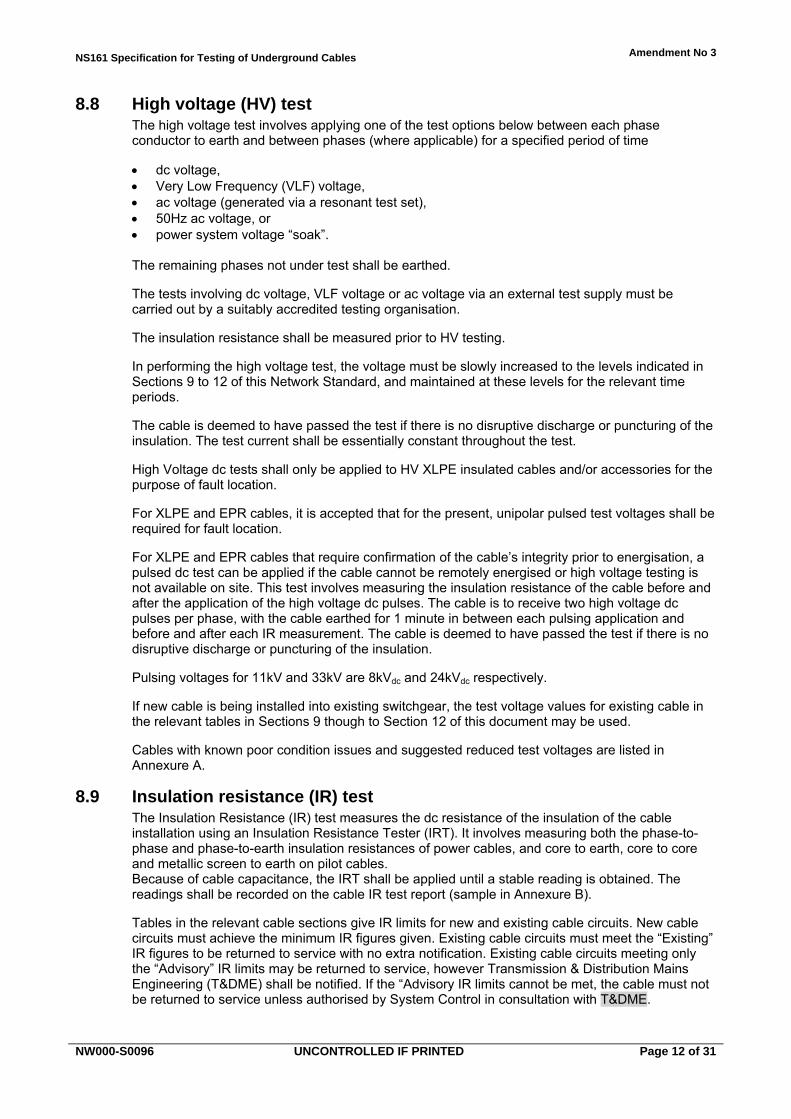
High voltage (HV) test 8.8The high voltage test involves applying one of the test options below between each phase conductor to earth and between phases (where applicable) for a specified period of time
dc voltage, Very Low Frequency (VLF) voltage, ac voltage (generated via a resonant test set), 50Hz ac voltage, or power system voltage “soak”.
The remaining phases not under test shall be earthed.
The tests involving dc voltage, VLF voltage or ac voltage via an external test supply must be carried out by a suitably accredited testing organisation.
The insulation resistance shall be measured prior to HV testing.
In performing the high voltage test, the voltage must be slowly increased to the levels indicated in Sections 9 to 12 of this Network Standard, and maintained at these levels for the relevant time periods.
The cable is deemed to have passed the test if there is no disruptive discharge or puncturing of the insulation. The test current shall be essentially constant throughout the test.
High Voltage dc tests shall only be applied to HV XLPE insulated cables and/or accessories for the purpose of fault location.
For XLPE and EPR cables, it is accepted that for the present, unipolar pulsed test voltages shall be required for fault location.
For XLPE and EPR cables that require confirmation of the cable’s integrity prior to energisation, a pulsed dc test can be applied if the cable cannot be remotely energised or high voltage testing is not available on site. This test involves measuring the insulation resistance of the cable before and after the application of the high voltage dc pulses. The cable is to receive two high voltage dc pulses per phase, with the cable earthed for 1 minute in between each pulsing application and before and after each IR measurement. The cable is deemed to have passed the test if there is no disruptive discharge or puncturing of the insulation.
Pulsing voltages for 11kV and 33kV are 8kVdc and 24kVdc respectively.
If new cable is being installed into existing switchgear, the test voltage values for existing cable in the relevant tables in Sections 9 though to Section 12 of this document may be used.
Cables with known poor condition issues and suggested reduced test voltages are listed in Annexure A.
Insulation resistance (IR) test 8.9The Insulation Resistance (IR) test measures the dc resistance of the insulation of the cable installation using an Insulation Resistance Tester (IRT). It involves measuring both the phase-to-phase and phase-to-earth insulation resistances of power cables, and core to earth, core to core and metallic screen to earth on pilot cables. Because of cable capacitance, the IRT shall be applied until a stable reading is obtained. The readings shall be recorded on the cable IR test report (sample in Annexure B).
Tables in the relevant cable sections give IR limits for new and existing cable circuits. New cable circuits must achieve the minimum IR figures given. Existing cable circuits must meet the “Existing” IR figures to be returned to service with no extra notification. Existing cable circuits meeting only the “Advisory” IR limits may be returned to service, however Transmission & Distribution Mains Engineering (T&DME) shall be notified. If the “Advisory IR limits cannot be met, the cable must not be returned to service unless authorised by System Control in consultation with T&DME.
NS161 Specification for Testing of Underground Cables Amendment No 3
NW000-S0096 UNCONTROLLED IF PRINTED Page 13 of 31
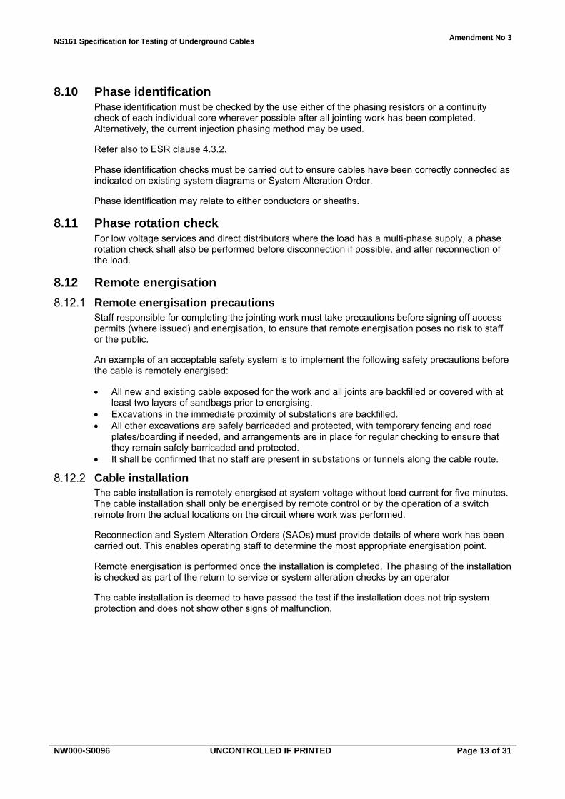
Phase identification 8.10Phase identification must be checked by the use either of the phasing resistors or a continuity check of each individual core wherever possible after all jointing work has been completed. Alternatively, the current injection phasing method may be used.
Refer also to ESR clause 4.3.2.
Phase identification checks must be carried out to ensure cables have been correctly connected as indicated on existing system diagrams or System Alteration Order.
Phase identification may relate to either conductors or sheaths.
Phase rotation check 8.11For low voltage services and direct distributors where the load has a multi-phase supply, a phase rotation check shall also be performed before disconnection if possible, and after reconnection of the load.
Remote energisation 8.12
Remote energisation precautions 8.12.1Staff responsible for completing the jointing work must take precautions before signing off access permits (where issued) and energisation, to ensure that remote energisation poses no risk to staff or the public.
An example of an acceptable safety system is to implement the following safety precautions before the cable is remotely energised:
All new and existing cable exposed for the work and all joints are backfilled or covered with at least two layers of sandbags prior to energising.
Excavations in the immediate proximity of substations are backfilled. All other excavations are safely barricaded and protected, with temporary fencing and road
plates/boarding if needed, and arrangements are in place for regular checking to ensure that they remain safely barricaded and protected.
It shall be confirmed that no staff are present in substations or tunnels along the cable route.
Cable installation 8.12.2The cable installation is remotely energised at system voltage without load current for five minutes. The cable installation shall only be energised by remote control or by the operation of a switch remote from the actual locations on the circuit where work was performed.
Reconnection and System Alteration Orders (SAOs) must provide details of where work has been carried out. This enables operating staff to determine the most appropriate energisation point.
Remote energisation is performed once the installation is completed. The phasing of the installation is checked as part of the return to service or system alteration checks by an operator
The cable installation is deemed to have passed the test if the installation does not trip system protection and does not show other signs of malfunction.
NS161 Specification for Testing of Underground Cables Amendment No 3
NW000-S0096 UNCONTROLLED IF PRINTED Page 14 of 31
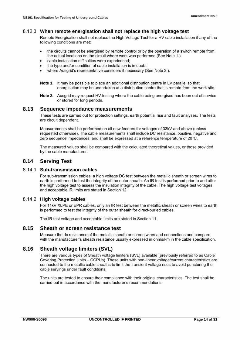
When remote energisation shall not replace the high voltage test 8.12.3Remote Energisation shall not replace the High Voltage Test for a HV cable installation if any of the following conditions are met:
the circuits cannot be energised by remote control or by the operation of a switch remote from the actual locations on the circuit where work was performed (See Note 1.).
cable installation difficulties were experienced; the type and/or condition of cable installation is in doubt; where Ausgrid’s representative considers it necessary (See Note 2.).
Note 1. It may be possible to place an additional distribution centre in LV parallel so that energisation may be undertaken at a distribution centre that is remote from the work site.
Note 2. Ausgrid may request HV testing where the cable being energised has been out of service or stored for long periods.
Sequence impedance measurements 8.13These tests are carried out for protection settings, earth potential rise and fault analyses. The tests are circuit dependent.
Measurements shall be performed on all new feeders for voltages of 33kV and above (unless requested otherwise). The cable measurements shall include DC resistance, positive, negative and zero sequence impedances, and shall be expressed at a reference temperature of 20C.
The measured values shall be compared with the calculated theoretical values, or those provided by the cable manufacturer.
Serving Test 8.14
Sub-transmission cables 8.14.1For sub-transmission cables, a high voltage DC test between the metallic sheath or screen wires to earth is performed to test the integrity of the outer sheath. An IR test is performed prior to and after the high voltage test to assess the insulation integrity of the cable. The high voltage test voltages and acceptable IR limits are stated in Section 12.
High voltage cables 8.14.2For 11kV XLPE or EPR cables, only an IR test between the metallic sheath or screen wires to earth is performed to test the integrity of the outer sheath for direct-buried cables.
The IR test voltage and acceptable limits are stated in Section 11.
Sheath or screen resistance test 8.15Measure the dc resistance of the metallic sheath or screen wires and connections and compare with the manufacturer’s sheath resistance usually expressed in ohms/km in the cable specification.
Sheath voltage limiters (SVL) 8.16There are various types of Sheath voltage limiters (SVL) available (previously referred to as Cable Covering Protection Units – CCPUs). These units with non-linear voltage/current characteristics are connected to the metallic cable sheaths to limit the transient voltage rises to avoid puncturing the cable servings under fault conditions.
The units are tested to ensure their compliance with their original characteristics. The test shall be carried out in accordance with the manufacturer’s recommendations.
NS161 Specification for Testing of Underground Cables Amendment No 3
NW000-S0096 UNCONTROLLED IF PRINTED Page 15 of 31
PILOT CABLE INSTALLATIONS 9.0
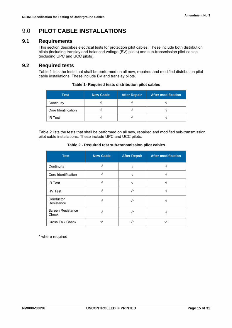
Requirements 9.1This section describes electrical tests for protection pilot cables. These include both distribution pilots (including translay and balanced voltage (BV) pilots) and sub-transmission pilot cables (including UPC and UCC pilots).
Required tests 9.2Table 1 lists the tests that shall be performed on all new, repaired and modified distribution pilot cable installations. These include BV and translay pilots.
Table 1- Required tests distribution pilot cables
Test New Cable After Repair After modification
Continuity √ √ √
Core Identification √ √ √
IR Test √ √ √
Table 2 lists the tests that shall be performed on all new, repaired and modified sub-transmission pilot cable installations. These include UPC and UCC pilots.
Table 2 - Required test sub-transmission pilot cables
Test New Cable After Repair After modification
Continuity √ √ √
Core Identification √ √ √
IR Test √ √ √
HV Test √ √* √
Conductor Resistance
√ √* √
Screen Resistance Check
√ √* √
Cross Talk Check √* √* √*
* where required
NS161 Specification for Testing of Underground Cables Amendment No 3
NW000-S0096 UNCONTROLLED IF PRINTED Page 16 of 31
Continuity and core identification 9.3
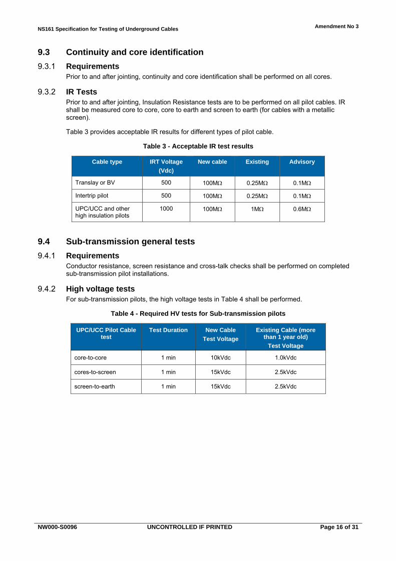
Requirements 9.3.1Prior to and after jointing, continuity and core identification shall be performed on all cores.
IR Tests 9.3.2Prior to and after jointing, Insulation Resistance tests are to be performed on all pilot cables. IR shall be measured core to core, core to earth and screen to earth (for cables with a metallic screen).
Table 3 provides acceptable IR results for different types of pilot cable.
Table 3 - Acceptable IR test results
Cable type IRT Voltage
(Vdc)
New cable Existing Advisory
Translay or BV 500 100M 0.25M 0.1M
Intertrip pilot 500 100M 0.25M 0.1M
UPC/UCC and other high insulation pilots
1000 100M 1M 0.6M
Sub-transmission general tests 9.4
Requirements 9.4.1Conductor resistance, screen resistance and cross-talk checks shall be performed on completed sub-transmission pilot installations.
High voltage tests 9.4.2For sub-transmission pilots, the high voltage tests in Table 4 shall be performed.
Table 4 - Required HV tests for Sub-transmission pilots
UPC/UCC Pilot Cable test
Test Duration New Cable
Test Voltage
Existing Cable (more than 1 year old)
Test Voltage
core-to-core 1 min 10kVdc 1.0kVdc
cores-to-screen 1 min 15kVdc 2.5kVdc
screen-to-earth 1 min 15kVdc 2.5kVdc
NS161 Specification for Testing of Underground Cables Amendment No 3
NW000-S0096 UNCONTROLLED IF PRINTED Page 17 of 31
LV CABLE INSTALLATIONS 10.0
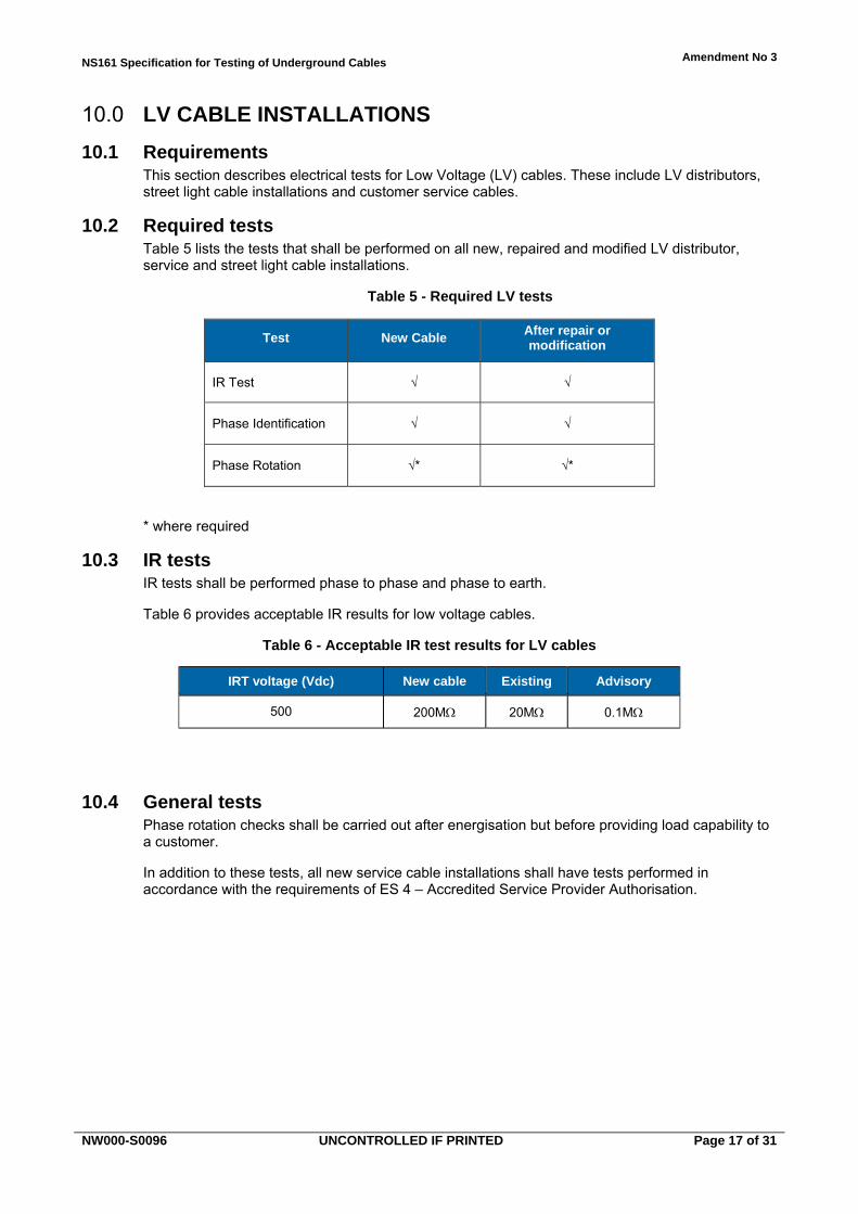
Requirements 10.1This section describes electrical tests for Low Voltage (LV) cables. These include LV distributors, street light cable installations and customer service cables.
Required tests 10.2Table 5 lists the tests that shall be performed on all new, repaired and modified LV distributor, service and street light cable installations.
Table 5 - Required LV tests
Test New Cable After repair or modification
IR Test √ √
Phase Identification √ √
Phase Rotation √* √*
* where required
IR tests 10.3IR tests shall be performed phase to phase and phase to earth.
Table 6 provides acceptable IR results for low voltage cables.
Table 6 - Acceptable IR test results for LV cables
IRT voltage (Vdc) New cable Existing Advisory
500 200M 20M 0.1M
General tests 10.4Phase rotation checks shall be carried out after energisation but before providing load capability to a customer.
In addition to these tests, all new service cable installations shall have tests performed in accordance with the requirements of ES 4 – Accredited Service Provider Authorisation.

NS161 Specification for Testing of Underground Cables Amendment No 3
NW000-S0096 UNCONTROLLED IF PRINTED Page 18 of 31
HV (5 AND 11 KV) CABLE INSTALLATIONS 11.0
Requirements 11.1This section describes electrical tests for High Voltage (HV) cables rated from 5kV to 11kV.
Required tests 11.2Table 7 lists the tests that shall be performed on all new, repaired and modified HV feeder cable installations.
Table 7 - Tests required on HV feeder cables
Test New Cable After repair or modification
IR Test √ √
Phase Identification √ √
HV Test √* √*
* Where remote energisation cannot be performed (Clause 8.12.2)
IR tests 11.3
Requirements 11.3.1IR tests shall be performed phase to phase, phase to earth and screen to earth (for direct laid cables). For newly laid, repaired and modified cable circuits, IR tests shall be performed (a) between laying and jointing each section of cable, and (b) once all jointing works are complete.
IR Tests ensure a new, repaired or modified cable is fit for duty and assists in fault location prior to jointing.
Table 8 provides acceptable IR results for HV cables.
Table 8 - Acceptable IR results
Cable Type IRT voltage (Vdc)
New cable Existing
XLPE or EPR 500-1000Vdc 200M 100M
Notes:
1. Values below 500k can indicate sheath damage. Values between 1M and 10M may not indicate damage in a single location. Fault finding can therefore be very difficult.
2. In the case of existing cables i.e. those already laid where the cable has passed a HV test, but has an IR result of less than 100M then the cable is deemed fit for service and shall be placed into service. The definition of existing cables includes such cables already laid with line joints completed but not yet placed into service.
NS161 Specification for Testing of Underground Cables Amendment No 3
NW000-S0096 UNCONTROLLED IF PRINTED Page 19 of 31
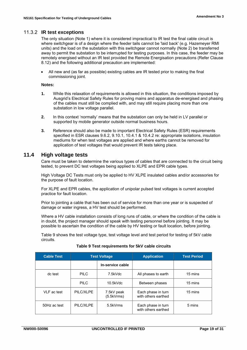
IR test exceptions 11.3.2The only situation (Note 1) where it is considered impractical to IR test the final cable circuit is where switchgear is of a design where the feeder tails cannot be 'laid back' (e.g. Hazemeyer RMI units) and the load on the substation with this switchgear cannot normally (Note 2) be transferred away to permit the substation to be interrupted for testing purposes. In this case, the feeder may be remotely energised without an IR test provided the Remote Energisation precautions (Refer Clause 8.12) and the following additional precaution are implemented:
All new and (as far as possible) existing cables are IR tested prior to making the final commissioning joint.
Notes:
1. While this relaxation of requirements is allowed in this situation, the conditions imposed by Ausgrid’s Electrical Safety Rules for proving mains and apparatus de-energised and phasing of the cables must still be complied with, and may still require placing more than one substation in low voltage parallel.
2. In this context ‘normally’ means that the substation can only be held in LV parallel or supported by mobile generator outside normal business hours.
3. Reference should also be made to important Electrical Safety Rules (ESR) requirements specified in ESR clauses 9.6.2, 9.10.1, 10.4.1 & 10.4.2 re: appropriate isolations, insulation mediums for when test voltages are applied and where earths cannot be removed for application of test voltages that would prevent IR tests taking place.
High voltage tests 11.4Care must be taken to determine the various types of cables that are connected to the circuit being tested, to prevent DC test voltages being applied to XLPE and EPR cable types.
High Voltage DC Tests must only be applied to HV XLPE insulated cables and/or accessories for the purpose of fault location.
For XLPE and EPR cables, the application of unipolar pulsed test voltages is current accepted practice for fault location.
Prior to jointing a cable that has been out of service for more than one year or is suspected of damage or water ingress, a HV test should be performed.
Where a HV cable installation consists of long runs of cable, or where the condition of the cable is in doubt, the project manager should speak with testing personnel before jointing. It may be possible to ascertain the condition of the cable by HV testing or fault location, before jointing.
Table 9 shows the test voltage type, test voltage level and test period for testing of 5kV cable circuits.
Table 9 Test requirements for 5kV cable circuits
Cable Test Test Voltage Application Test Period
In-service cable
dc test PILC 7.5kVdc All phases to earth 15 mins
PILC 10.5kVdc Between phases 15 mins
VLF ac test PILC/XLPE 7.5kV peak (5.5kVrms)
Each phase in turn with others earthed
15 mins
50Hz ac test PILC/XLPE 5.5kVrms Each phase in turn with others earthed
5 mins
NS161 Specification for Testing of Underground Cables Amendment No 3
NW000-S0096 UNCONTROLLED IF PRINTED Page 20 of 31
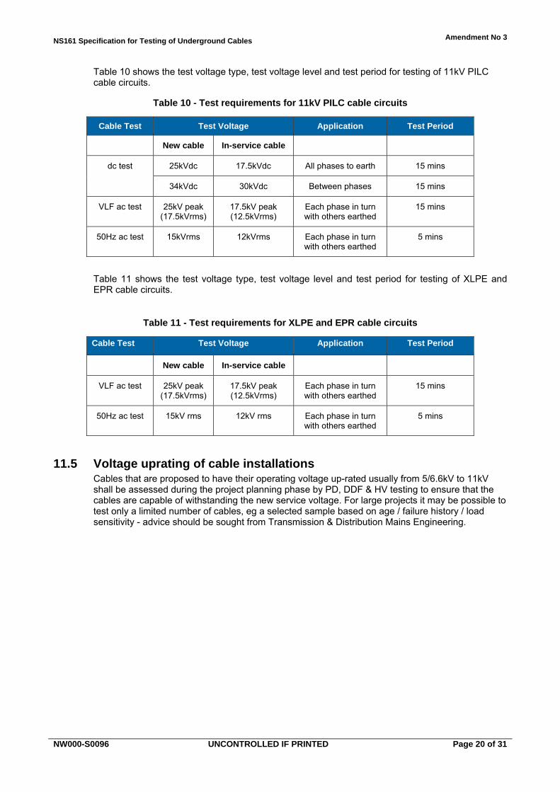
Table 10 shows the test voltage type, test voltage level and test period for testing of 11kV PILC cable circuits.
Table 10 - Test requirements for 11kV PILC cable circuits
Cable Test Test Voltage Application Test Period
New cable In-service cable
dc test 25kVdc 17.5kVdc All phases to earth 15 mins
34kVdc 30kVdc Between phases 15 mins
VLF ac test 25kV peak (17.5kVrms)
17.5kV peak (12.5kVrms)
Each phase in turn with others earthed
15 mins
50Hz ac test 15kVrms 12kVrms Each phase in turn with others earthed
5 mins
Table 11 shows the test voltage type, test voltage level and test period for testing of XLPE and EPR cable circuits.
Table 11 - Test requirements for XLPE and EPR cable circuits
Cable Test Test Voltage Application Test Period
New cable In-service cable
VLF ac test 25kV peak (17.5kVrms)
17.5kV peak (12.5kVrms)
Each phase in turn with others earthed
15 mins
50Hz ac test 15kV rms 12kV rms Each phase in turn with others earthed
5 mins
Voltage uprating of cable installations 11.5Cables that are proposed to have their operating voltage up-rated usually from 5/6.6kV to 11kV shall be assessed during the project planning phase by PD, DDF & HV testing to ensure that the cables are capable of withstanding the new service voltage. For large projects it may be possible to test only a limited number of cables, eg a selected sample based on age / failure history / load sensitivity - advice should be sought from Transmission & Distribution Mains Engineering.

NS161 Specification for Testing of Underground Cables Amendment No 3
NW000-S0096 UNCONTROLLED IF PRINTED Page 21 of 31
SUB-TRANSMISSION CABLE INSTALLATIONS 12.0
Requirements 12.1This section describes electrical tests for sub-transmission cable installations. Non-electrical tests for Fluid Filled cables are described in Section 13.
The testing requirements for sub-transmission cable installations vary according to operating voltage and cable type.
Required tests 12.2Table 12 provides the tests that are required prior to each sub-transmission cable being energised.
Table 12 - Required pre-energisation tests for sub-transmission cables
Test Commissioning After repair After modification
IR Test (conductor) √ √ √
Conductor Resistance Test
√ √ √
Phase Identification (conductor)
√ √* √
Sheath Resistance Test
√ √* √
Phase Identification (sheath)
√** √** √**
Cross-bonding Test √** √**
SVL Test √** √** √**
Sequence Impedance Measurements
√ √*
Serving Test √ √ √
High Voltage Test (conductor)
√ √ √
* As appropriate for the particular repair or modification. ** Single core cables.
NS161 Specification for Testing of Underground Cables Amendment No 3
NW000-S0096 UNCONTROLLED IF PRINTED Page 22 of 31
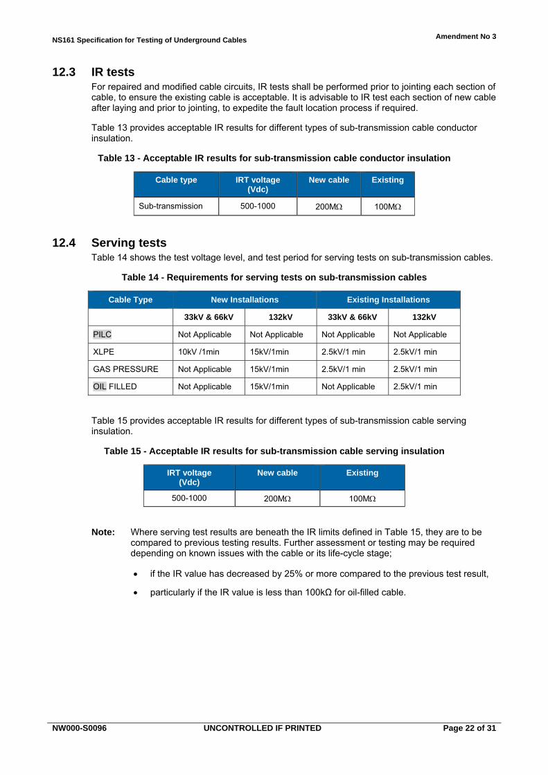
IR tests 12.3For repaired and modified cable circuits, IR tests shall be performed prior to jointing each section of cable, to ensure the existing cable is acceptable. It is advisable to IR test each section of new cable after laying and prior to jointing, to expedite the fault location process if required.
Table 13 provides acceptable IR results for different types of sub-transmission cable conductor insulation.
Table 13 - Acceptable IR results for sub-transmission cable conductor insulation
Cable type IRT voltage (Vdc)
New cable Existing
Sub-transmission 500-1000 200M 100M
Serving tests 12.4Table 14 shows the test voltage level, and test period for serving tests on sub-transmission cables.
Table 14 - Requirements for serving tests on sub-transmission cables
Cable Type New Installations Existing Installations
33kV & 66kV 132kV 33kV & 66kV 132kV
PILC Not Applicable Not Applicable Not Applicable Not Applicable
XLPE 10kV /1min 15kV/1min 2.5kV/1 min 2.5kV/1 min
GAS PRESSURE Not Applicable 15kV/1min 2.5kV/1 min 2.5kV/1 min
OIL FILLED Not Applicable 15kV/1min Not Applicable 2.5kV/1 min
Table 15 provides acceptable IR results for different types of sub-transmission cable serving insulation.
Table 15 - Acceptable IR results for sub-transmission cable serving insulation
IRT voltage (Vdc)
New cable Existing
500-1000 200M 100M
Note: Where serving test results are beneath the IR limits defined in Table 15, they are to be compared to previous testing results. Further assessment or testing may be required depending on known issues with the cable or its life-cycle stage;
if the IR value has decreased by 25% or more compared to the previous test result,
particularly if the IR value is less than 100kΩ for oil-filled cable.

NS161 Specification for Testing of Underground Cables Amendment No 3
NW000-S0096 UNCONTROLLED IF PRINTED Page 23 of 31
High voltage tests 12.5For new cables, these tests shall be performed after laying and bedding. For existing and modified cables, the tests shall be performed after backfilling of joints, prior to surface restoration works. Electrical tests shall be performed after cable damage where it is suspected that electrical failure has been involved, or there is a possibility of future failure at the damage area.
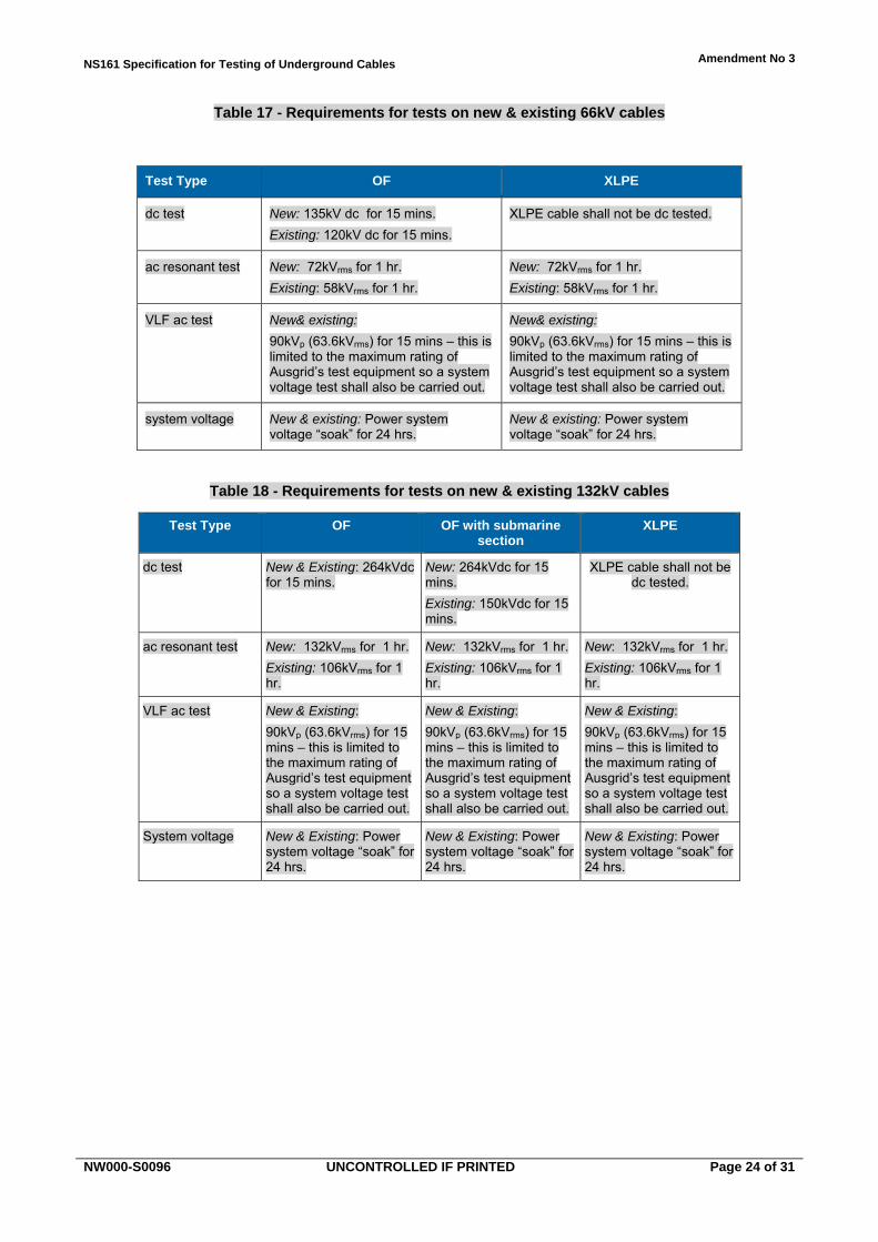
Tables 16, 17 & 18 show the test voltages and test times for 33kV, 66kV and 132kV sub-transmission cables.
For feeders that comprise a mix of new & existing cables and/or different cable types, the test voltage shall be the minimum value of the test voltages for each individual cable section. The test type shall be chosen in descending order of those listed in Tables 16, 17 & 18, subject to test equipment limitations. If test equipment limitations prevent the full dc, VLF ac or resonant test voltage being applied then the power system “soak” test shall be carried out instead.
Approval may be sought from Transmission & Distribution Mains Engineering to reduce these testing requirements on a case by case basis for cables with known problem, if needed to extend their service life.
General tests 12.6An additional check for Gas Pressure cables after jointing but prior to installing the coffin, is to pressurise the joint sleeves and check there are no leaks. Prior to restoring the cable to service, check gas alarms and reset with all cylinders being at their operating pressures. Where Gas Pressure cable has experienced crush damage to the cable sheath or serving, a serving test shall be performed.
An additional check for cross-bonded cable installations where an existing joint was disturbed and the connections removed during repairs, is to perform a phasing check from the box through to the next cross-bonding box.
SVL checks must be performed after repair where the cable has carried fault current.
Table 16 - Requirements for tests on new & existing 33kV cables
Test Type PILC GP XLPE
dc test New: 75kV dc for 15 mins.
Existing: 45kV dc for 15 mins.
New: 75kV dc for 15 mins.
Existing: 45kV dc for 15 mins.
XLPE cable shall not be dc tested.
VLF ac test New: 75kVp (53kVrms) for 15 mins.
Existing: 45kVp (31.8kVrms) for 15 mins.
New: 75kVp (53kVrms) for 15 mins.
Existing: 45kVp (31.8kVrms) for 15 mins.
New: 75kVp (53kVrms) for 15 mins.
Existing: 60kVp (42.4kVrms) for 15 mins.
ac resonant test New: 33kVrms for 15 mins
Existing: 26kVrms for 15 mins.
New: 33kVrms for 15 mins
Existing: 26kVrms for 15 mins.
New: 33kVrms for 15 mins.
Existing: 26kVrms for 15 mins.
system voltage New & existing: Power system voltage “soak” for 24 hrs.
New & existing: Power system voltage “soak” for 24 hrs.
New & existing: Power system voltage “soak” for 24 hours.
NS161 Specification for Testing of Underground Cables Amendment No 3
NW000-S0096 UNCONTROLLED IF PRINTED Page 24 of 31
Table 17 - Requirements for tests on new & existing 66kV cables
Test Type OF XLPE
dc test New: 135kV dc for 15 mins.
Existing: 120kV dc for 15 mins.
XLPE cable shall not be dc tested.
ac resonant test New: 72kVrms for 1 hr.
Existing: 58kVrms for 1 hr.
New: 72kVrms for 1 hr.
Existing: 58kVrms for 1 hr.
VLF ac test New& existing:
90kVp (63.6kVrms) for 15 mins – this is limited to the maximum rating of Ausgrid’s test equipment so a system voltage test shall also be carried out.
New& existing:
90kVp (63.6kVrms) for 15 mins – this is limited to the maximum rating of Ausgrid’s test equipment so a system voltage test shall also be carried out.
system voltage New & existing: Power system voltage “soak” for 24 hrs.
New & existing: Power system voltage “soak” for 24 hrs.
Table 18 - Requirements for tests on new & existing 132kV cables
Test Type OF OF with submarine section
XLPE
dc test New & Existing: 264kVdc for 15 mins.
New: 264kVdc for 15 mins.
Existing: 150kVdc for 15 mins.
XLPE cable shall not be dc tested.
ac resonant test New: 132kVrms for 1 hr.
Existing: 106kVrms for 1 hr.
New: 132kVrms for 1 hr.
Existing: 106kVrms for 1 hr.
New: 132kVrms for 1 hr.
Existing: 106kVrms for 1 hr.
VLF ac test New & Existing:
90kVp (63.6kVrms) for 15 mins – this is limited to the maximum rating of Ausgrid’s test equipment so a system voltage test shall also be carried out.
New & Existing:
90kVp (63.6kVrms) for 15 mins – this is limited to the maximum rating of Ausgrid’s test equipment so a system voltage test shall also be carried out.
New & Existing:
90kVp (63.6kVrms) for 15 mins – this is limited to the maximum rating of Ausgrid’s test equipment so a system voltage test shall also be carried out.
System voltage New & Existing: Power system voltage “soak” for 24 hrs.
New & Existing: Power system voltage “soak” for 24 hrs.
New & Existing: Power system voltage “soak” for 24 hrs.
NS161 Specification for Testing of Underground Cables Amendment No 3
NW000-S0096 UNCONTROLLED IF PRINTED Page 25 of 31
OIL SAMPLE TESTING REQUIREMENTS 13.0
General 13.1Oil samples shall be taken from all 132kV oil-filled cables and accessories during scheduled maintenance and submitted to Ausgrid’s testing laboratory for analysis. The purpose of the tests is to provide Ausgrid with data that can be used to determine degradation of a cable and other metrics for identifying possible failure modes, reliability and life cycle factors.
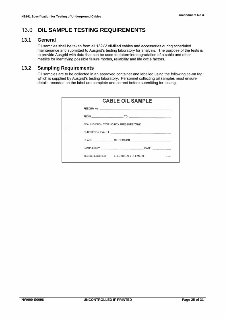
Sampling Requirements 13.2Oil samples are to be collected in an approved container and labelled using the following tie-on tag, which is supplied by Ausgrid’s testing laboratory. Personnel collecting oil samples must ensure details recorded on the label are complete and correct before submitting for testing.
NS161 Specification for Testing of Underground Cables Amendment No 3
NW000-S0096 UNCONTROLLED IF PRINTED Page 26 of 31
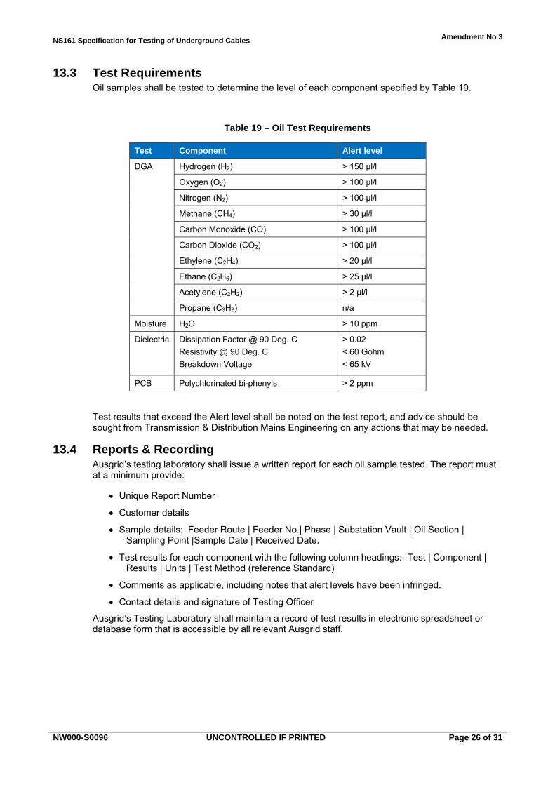
Test Requirements 13.3Oil samples shall be tested to determine the level of each component specified by Table 19.
Table 19 – Oil Test Requirements
Test Component Alert level
DGA Hydrogen (H2) > 150 µl/l
Oxygen (O2) > 100 µl/l
Nitrogen (N2) > 100 µl/l
Methane (CH4) > 30 µl/l
Carbon Monoxide (CO) > 100 µl/l
Carbon Dioxide (CO2) > 100 µl/l
Ethylene (C2H4) > 20 µl/l
Ethane (C2H6) > 25 µl/l
Acetylene (C2H2) > 2 µl/l
Propane (C3H8) n/a
Moisture H2O > 10 ppm
Dielectric Dissipation Factor @ 90 Deg. C
Resistivity @ 90 Deg. C
Breakdown Voltage
> 0.02
< 60 Gohm
< 65 kV
PCB Polychlorinated bi-phenyls > 2 ppm
Test results that exceed the Alert level shall be noted on the test report, and advice should be sought from Transmission & Distribution Mains Engineering on any actions that may be needed.
Reports & Recording 13.4Ausgrid’s testing laboratory shall issue a written report for each oil sample tested. The report must at a minimum provide:
Unique Report Number
Customer details
Sample details: Feeder Route | Feeder No.| Phase | Substation Vault | Oil Section | Sampling Point |Sample Date | Received Date.
Test results for each component with the following column headings:- Test | Component | Results | Units | Test Method (reference Standard)
Comments as applicable, including notes that alert levels have been infringed.
Contact details and signature of Testing Officer
Ausgrid’s Testing Laboratory shall maintain a record of test results in electronic spreadsheet or database form that is accessible by all relevant Ausgrid staff.
NS161 Specification for Testing of Underground Cables Amendment No 3
NW000-S0096 UNCONTROLLED IF PRINTED Page 27 of 31
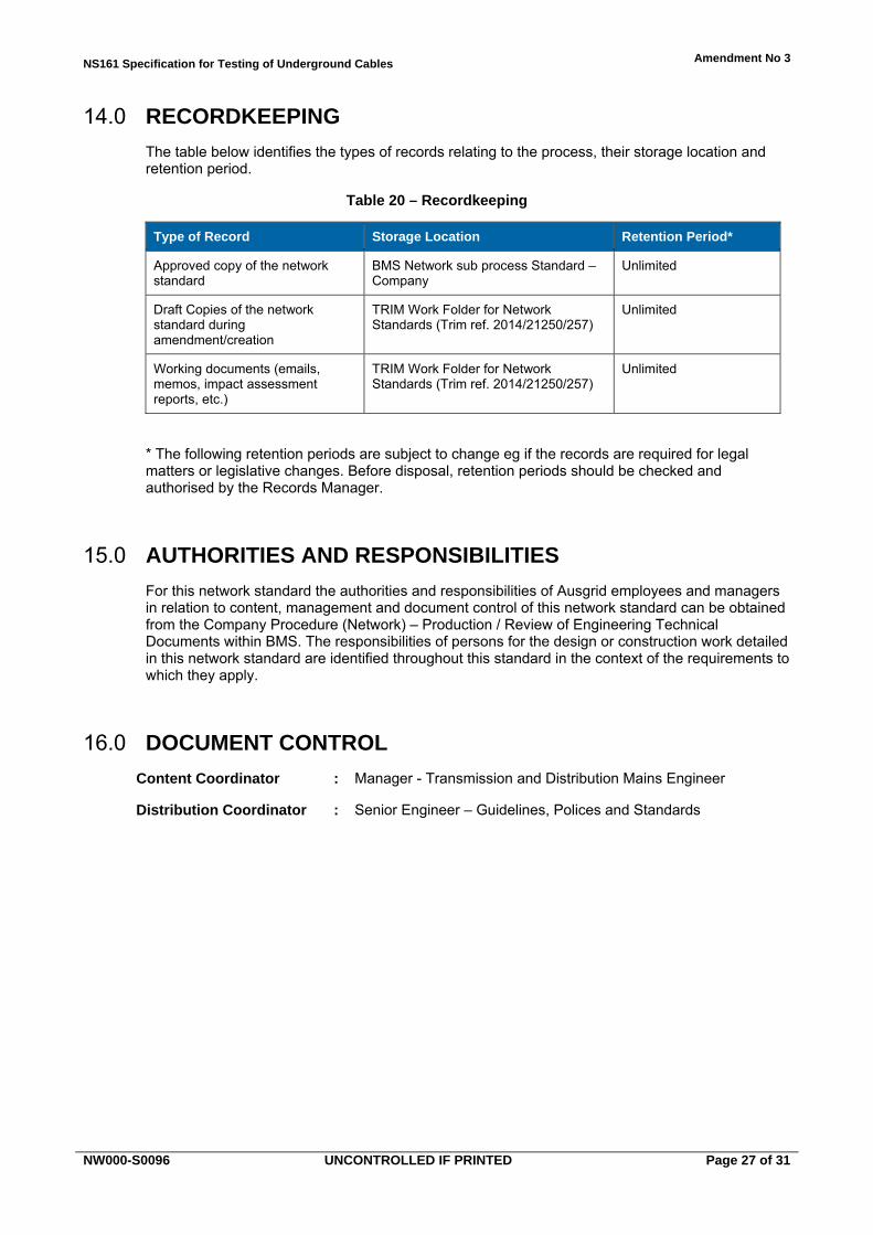
RECORDKEEPING 14.0
The table below identifies the types of records relating to the process, their storage location and retention period.
Table 20 – Recordkeeping
Type of Record Storage Location Retention Period*
Approved copy of the network standard
BMS Network sub process Standard – Company
Unlimited
Draft Copies of the network standard during amendment/creation
TRIM Work Folder for Network Standards (Trim ref. 2014/21250/257)
Unlimited
Working documents (emails, memos, impact assessment reports, etc.)
TRIM Work Folder for Network Standards (Trim ref. 2014/21250/257)
Unlimited
* The following retention periods are subject to change eg if the records are required for legal matters or legislative changes. Before disposal, retention periods should be checked and authorised by the Records Manager.
AUTHORITIES AND RESPONSIBILITIES 15.0
For this network standard the authorities and responsibilities of Ausgrid employees and managers in relation to content, management and document control of this network standard can be obtained from the Company Procedure (Network) – Production / Review of Engineering Technical Documents within BMS. The responsibilities of persons for the design or construction work detailed in this network standard are identified throughout this standard in the context of the requirements to which they apply.
DOCUMENT CONTROL 16.0
Content Coordinator : Manager - Transmission and Distribution Mains Engineer
Distribution Coordinator : Senior Engineer – Guidelines, Polices and Standards

NS161 Specification for Testing of Underground Cables Amendment No 3
NW000-S0096 UNCONTROLLED IF PRINTED Page 28 of 31
Annexure A – Testing of selected 132kV cable circuits
The normally accepted test voltages applied in Section 11 should be reduced where special circumstances warrant it; for example, in the case where submarine cables are involved, or where an installation contains elements (such as specific joints) which are known to be prone to failure.
Table A1 lists existing 132kV cable installations that have special conditions, and suggests maximum test voltages to be applied should the occasion arise. Included in the schedule are ex-ECNSW, ex-SCC and ex-SE feeders.
Table A1 - Reduced test voltages for selected 132kV cable installations
Feeder Destination Cable Make Suggested Test Voltage (kVdc)
Reasons for reduced test voltage
929 Lane Cove - Dalley St Sumitomo 150 Submarine cable
928/3 Lane Cove - Dalley St Sumitomo 150 Submarine cable
92L/1 Dalley St - Surry Hills Pirelli 150 Suspect joints
92L/3 Lane Cove - Dalley St Pirelli 150 Submarine cable
92M Lane Cove-Surry Hills Tee Lane Cove - Dalley St
Pirelli 150 Submarine cable

NS161 Specification for Testing of Underground Cables Amendment No 3
NW000-S0096 UNCONTROLLED IF PRINTED Page 29 of 31
Annexure B - Sample IR test report
To: Supervisor ____________________
CABLE INSULATION RESISTANCE (IR) TEST REPORT Time: _______________________ Date: _____________
Location/Project: __________________________________________________
Procedure:
Phase-to-Phase and Phase-to-Earth IR readings are to be taken before and after jointing works.
Equipment:
500V Megger with minimum range 200MΩ
Instrument No.:________________________________ Calibration Date:_____________________________
Minimum IR Values for Power Cables (from NS 161 Clause 9.4.2):
Cable Type New Cable Existing Cable(1) Advisory(2)
Low Voltage 200MΩ 20MΩ 0.1MΩ
High Voltage 200MΩ 100MΩ 5MΩ
"Existing Cable" are cables that have been in service or are older than 1 yr. If "Existing Cable" values are not achieved but "Advisory" are, the cable may be returned to service but the results must be reported to your Supervisor.
If "Advisory" values are not achieved, the matter must be referred to your Supervisor who will make a decision with the System Operator as to whether the cable shall be returned to service. Alternatively, Network Test may be contacted to arrange a cable test.
Results:
Cable Type/Description: _________________________________
Before A-B A-N A-E A-C B-N B-E PASS / FAIL B-C C-N C-E
After A-B A-N A-E
A-C B-N B-E PASS / FAIL B-C C-N C-E
Comments:______________________________________________________________________
Cable Type/Description: _________________________________
Before A-B A-N A-E A-C B-N B-E PASS / FAIL B-C C-N C-E
After A-B A-N A-E
A-C B-N B-E PASS / FAIL B-C C-N C-E
Comments:_______________________________________________________________________
Tested By:________________________ Signature:________________________
NS161 Specification for Testing of Underground Cables Amendment No 2
NW000-S0096 UNCONTROLLED IF PRINTED Page 30 of 31
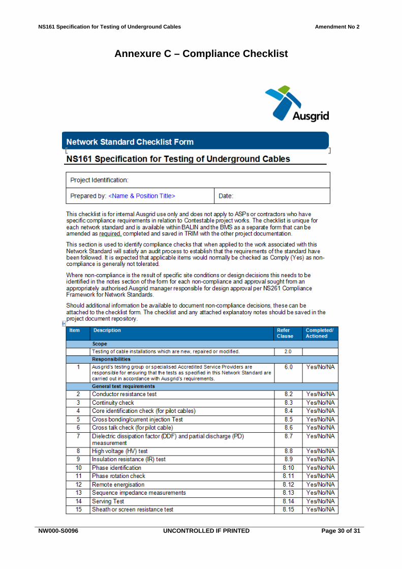
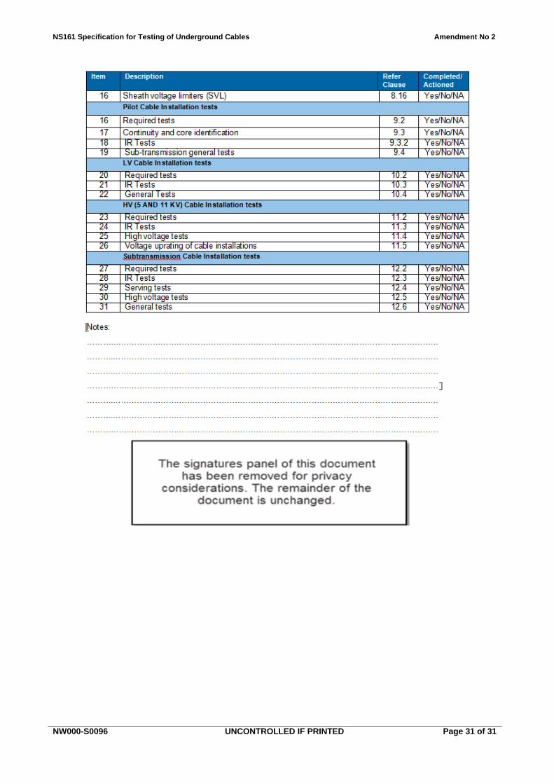
Annexure C – Compliance Checklist
NS161 Specification for Testing of Underground Cables Amendment No 2
NW000-S0096 UNCONTROLLED IF PRINTED Page 31 of 31