Network Services Framework v1 - ogf.org
21
GFD.173 Guy Roberts NSI-WG Tomohiro Kudoh Inder Monga Jerry Sobieski John Vollbrecht Network Services Framework v1.0 Status of This Document This document provides information to the Grid community on the service interface between a requesting software agent and a provider software agent that offers and delivers a Network Service. It is intended to describe the processes and environment in which software agents interact to deliver the service(s). Representing applications or other networks, these agents may request certain services from other network agents. Distribution is unlimited. Copyright Notice Copyright © Open Grid Forum (2008-2010). All Rights Reserved. Trademark OGSA is a registered trademark and service mark of the Open Grid Forum. Abstract Version 1.0 of the Network Services Framework describes a framework to support the request and management of Network Services; it allows an application or network provider to request Network Services from other network providers. The framework covers the interface, protocols, agents and associated services. The Network Service Interface (NSI) is the interface between two software agents that communicate via the NSI protocol. This document should be read in conjunction with each of the NSI Network Service informational documents and its counterpart protocol recommendation. Contents 1. Context and Overview .............................................................................................................. 2 2. Network Services Framework .................................................................................................. 3 2.1 Network Services .............................................................................................................. 3 2.2 The Network Service Interface .......................................................................................... 3 2.3 The Network Service Agent .............................................................................................. 4 2.3.1 The Network Resource Manager ............................................................................... 5 2.4 NSI Sessions .................................................................................................................... 5 2.5 NSI Extensibility ................................................................................................................ 6 2.6 The NSI Service Plane ...................................................................................................... 6 2.7 NSI Communications Models ............................................................................................ 7 3. The NSI Protocol ...................................................................................................................... 9 3.1 NSI Protocol Overview ...................................................................................................... 9 3.2 NSI Messages ................................................................................................................... 9 3.2.1 NSI Message Common Attributes ............................................................................. 9 3.3 NSI Service Definitions ................................................................................................... 10 3.4 Temporal Aspects of NSI Services ................................................................................. 11 3.5 Trust and Authentication in the NSI Protocol .................................................................. 11 3.6 NSI Service Plane Error Handling ................................................................................... 12 4. Representing Network Resources ......................................................................................... 13 4.1 Describing Network Topologies ...................................................................................... 13 4.2 Using Service Termination Points ................................................................................... 15 4.2.1 Service Termination Point ........................................................................................ 15 4.2.2 Service Demarcation Point ...................................................................................... 16 4.3 Managing Connections with the Intra-Network Topology ............................................... 16 5. Summary ................................................................................................................................ 18
Transcript of Network Services Framework v1 - ogf.org
GFD.173 Guy Roberts NSI-WG Tomohiro Kudoh
Inder Monga Jerry Sobieski
John Vollbrecht Network Services Framework v1.0 Status of This Document This document provides information to the Grid community on the service interface between a requesting software agent and a provider software agent that offers and delivers a Network Service. It is intended to describe the processes and environment in which software agents interact to deliver the service(s). Representing applications or other networks, these agents may request certain services from other network agents. Distribution is unlimited. Copyright Notice Copyright © Open Grid Forum (2008-2010). All Rights Reserved. Trademark OGSA is a registered trademark and service mark of the Open Grid Forum. Abstract Version 1.0 of the Network Services Framework describes a framework to support the request and management of Network Services; it allows an application or network provider to request Network Services from other network providers. The framework covers the interface, protocols, agents and associated services. The Network Service Interface (NSI) is the interface between two software agents that communicate via the NSI protocol. This document should be read in conjunction with each of the NSI Network Service informational documents and its counterpart protocol recommendation. Contents 1. Context and Overview .............................................................................................................. 2 2. Network Services Framework .................................................................................................. 3
2.1 Network Services .............................................................................................................. 3 2.2 The Network Service Interface .......................................................................................... 3 2.3 The Network Service Agent .............................................................................................. 4
2.3.1 The Network Resource Manager ............................................................................... 5 2.4 NSI Sessions .................................................................................................................... 5 2.5 NSI Extensibility ................................................................................................................ 6 2.6 The NSI Service Plane ...................................................................................................... 6 2.7 NSI Communications Models ............................................................................................ 7
3. The NSI Protocol ...................................................................................................................... 9 3.1 NSI Protocol Overview ...................................................................................................... 9 3.2 NSI Messages ................................................................................................................... 9
3.2.1 NSI Message Common Attributes ............................................................................. 9 3.3 NSI Service Definitions ................................................................................................... 10 3.4 Temporal Aspects of NSI Services ................................................................................. 11 3.5 Trust and Authentication in the NSI Protocol .................................................................. 11 3.6 NSI Service Plane Error Handling ................................................................................... 12
4. Representing Network Resources ......................................................................................... 13 4.1 Describing Network Topologies ...................................................................................... 13 4.2 Using Service Termination Points ................................................................................... 15
4.2.1 Service Termination Point ........................................................................................ 15 4.2.2 Service Demarcation Point ...................................................................................... 16
4.3 Managing Connections with the Intra-Network Topology ............................................... 16 5. Summary ................................................................................................................................ 18
GFD-I.173 NSI-WG 15 December, 2010
2
6. Contributors ............................................................................................................................ 18 7. Glossary ................................................................................................................................. 18 8. Intellectual Property Statement .............................................................................................. 20 9. Disclaimer .............................................................................................................................. 20 10. Full Copyright Notice .......................................................................................................... 20 11. References ......................................................................................................................... 21
1. Context and Overview Over the last decade, global networks have begun delivering high-performance transport services directly to applications that require performance levels or capabilities unavailable in conventional best-effort IP networks. The ability to create connections between a fixed set of ports worldwide, with specific, predictable, and often demanding performance characteristics, enables emerging global collaborations to establish well-defined and highly customized network environments to support the end users and their applications. This has been particularly true within the Research and Higher Education environment and the growing Grid community. Historically, connections across these transport networks have been reserved and provisioned in a variety of ways. The most common approach is manual provisioning – typically performed by a network engineer. More recently, some networking communities have developed tools and protocols to automate the process of network resource allocation and to allow the user or application to participate directly in the path creation process. These new approaches to automating transport connection provisioning are the basis for the standardization effort described in this recommendation. Automated connection-oriented transport provisioning capabilities are currently being deployed by Research and Education (R&E) providers as well as by commercial providers, and could eventually be implemented in home/retail networks as deployment progresses. These automated provisioning systems, while being developed independently by different groups, all have common elements. They have developed software-based control and/or management agents to regulate access to these resources, to schedule and reserve resources, to trigger or control timely provisioning of the network resources, and to monitor and release resources. These controllers are deployed in two different contexts. One context is application (or Grid) centric, where a network provides a resource to an application or middleware. The other context is network centric, where network resources are collaboratively shared among networks to expand or improve network performance or reach. In the former context, a user or application agent is requesting the service from a network provider. In the latter context, one network is interacting with one or more other networks to manage these resources and deliver a comprehensive and well-integrated service portfolio to the user community. This informational document defines a framework for the NSI protocol to support both of these contexts. The Network Services Framework (NSF) defines several key architectural elements: the Network Service Interface (NSI), the NSI Protocol, the Network Service Agent (NSA), the Network Services, and the Inter-Network Topology. These elements exist in a notional NSI Service Plane. The framework describes an environment within which network objects are defined as manageable resources. Within the framework, these network resources can be selected, allocated, interrogated, and manipulated by software agents on behalf of requesting users. Federated Network Services are delivered by combining the capabilities of participating providers. To manage federated services, a range of network-related functional capabilities such as topology sharing, path finding, resource reservation, hardware provisioning, and other ancillary services and functions are required.
GFD-I.173 NSI-WG 15 December, 2010
3
The NSI Protocol is defined by a suite of documents. This informational document describes the Network Services Framework version 1.0. In addition, each Network Service is defined in its own informational document and a counterpart protocol recommendation.
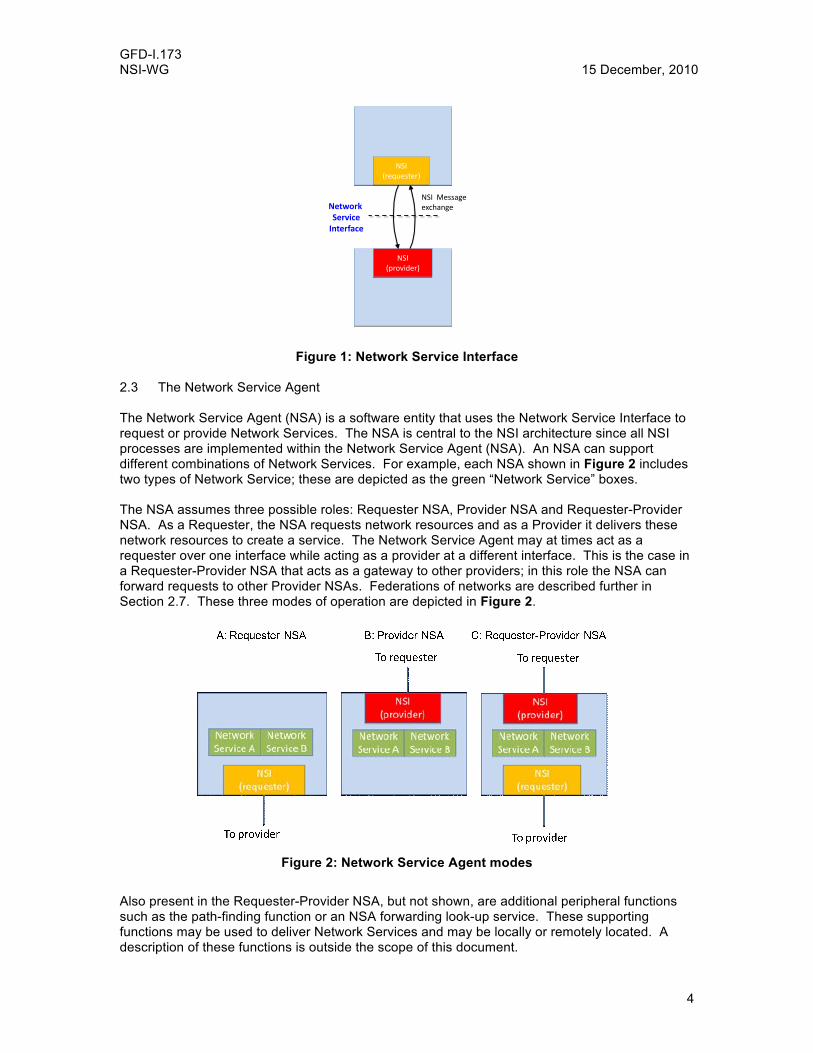
2. Network Services Framework This section discusses the architectural concepts that provide the Network Service context and high-level definitions used in the NSI Protocol recommendations. 2.1 Network Services Network Services allow applications to monitor, control, interrogate, and support the network resources that are made available by the provider of the network. Typical transport network resources include a range of technologies such as wavelengths delivered using ROADMs, TDM on cross-connect equipment or packet switches. The Network Service Framework is designed to deliver a wide range of Network Services using all of these technologies. An example of a Network Service is the Connection Service; this service is used to request and manage transport connections. Another example is the topology service; this is used to exchange network topologies. Service requests may originate from an application, from grid middleware, or from a network provider. A service can be requested by any application that has implemented an agent with a Network Service Interface. Similarly, the request can be serviced by any network provider who has implemented an agent with an NSI protocol interface. Each service has an associated Service Definition (SD). This SD sets the scope of the service and identifies any parameter that is needed for the request to be fulfilled. The NSI Protocol deals with an abstracted model of transport services. This abstract concept is a simplified and convenient means of presenting the key functional aspects of the service object while hiding most or all of the technical details and real-world complexities that are not relevant to the application. Similarly, the NSI Protocol manages network resources by using an abstracted model of these resources. This model is called the Inter-Network Topology and its concepts are described in this framework document. Each service is managed by an exchange of NSI Messages between agents. These messages operate using a set of service primitives. Service primitives are the set of instructions that allow the requester to set up and manage a service. Each service request will result in the allocation of a service id for the new service instance. In the remaining part of this section, the architectural components that make up the Network Services Framework are described. 2.2 The Network Service Interface The Network Service Interface (NSI) provides secure and reliable sessions for service-related communication between two NSAs. An instance of the NSI exists at the boundary between two communicating software agents: the Requester NSA and the Provider NSA. These agents interact to realize the delivery of a Network Service supported by the network infrastructure - the Requester NSA requests a service, and the Provider NSA delivers it (see Figure 1).
GFD-I.173 NSI-WG 15 December, 2010
4
NetworkServiceInterface
NSI Messageexchange
NSI (provider)
NSI (requester)
Figure 1: Network Service Interface 2.3 The Network Service Agent The Network Service Agent (NSA) is a software entity that uses the Network Service Interface to request or provide Network Services. The NSA is central to the NSI architecture since all NSI processes are implemented within the Network Service Agent (NSA). An NSA can support different combinations of Network Services. For example, each NSA shown in Figure 2 includes two types of Network Service; these are depicted as the green “Network Service” boxes. The NSA assumes three possible roles: Requester NSA, Provider NSA and Requester-Provider NSA. As a Requester, the NSA requests network resources and as a Provider it delivers these network resources to create a service. The Network Service Agent may at times act as a requester over one interface while acting as a provider at a different interface. This is the case in a Requester-Provider NSA that acts as a gateway to other providers; in this role the NSA can forward requests to other Provider NSAs. Federations of networks are described further in Section 2.7. These three modes of operation are depicted in Figure 2.
Figure 2: Network Service Agent modes
Also present in the Requester-Provider NSA, but not shown, are additional peripheral functions such as the path-finding function or an NSA forwarding look-up service. These supporting functions may be used to deliver Network Services and may be locally or remotely located. A description of these functions is outside the scope of this document.
GFD-I.173 NSI-WG 15 December, 2010
5
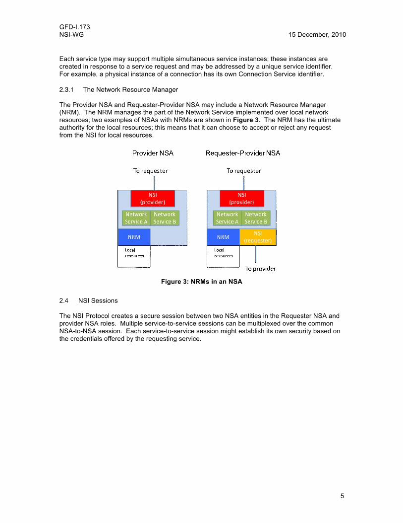
Each service type may support multiple simultaneous service instances; these instances are created in response to a service request and may be addressed by a unique service identifier. For example, a physical instance of a connection has its own Connection Service identifier. 2.3.1 The Network Resource Manager The Provider NSA and Requester-Provider NSA may include a Network Resource Manager (NRM). The NRM manages the part of the Network Service implemented over local network resources; two examples of NSAs with NRMs are shown in Figure 3. The NRM has the ultimate authority for the local resources; this means that it can choose to accept or reject any request from the NSI for local resources.
Figure 3: NRMs in an NSA
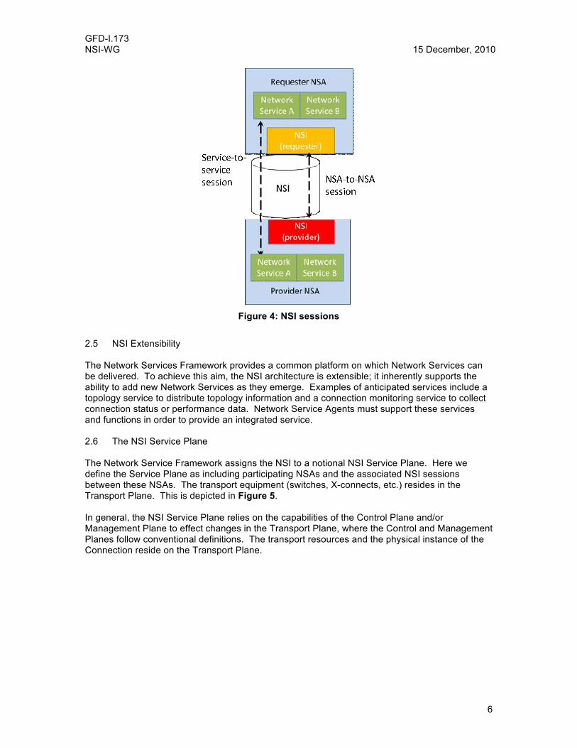
2.4 NSI Sessions The NSI Protocol creates a secure session between two NSA entities in the Requester NSA and provider NSA roles. Multiple service-to-service sessions can be multiplexed over the common NSA-to-NSA session. Each service-to-service session might establish its own security based on the credentials offered by the requesting service.
GFD-I.173 NSI-WG 15 December, 2010
6
Figure 4: NSI sessions
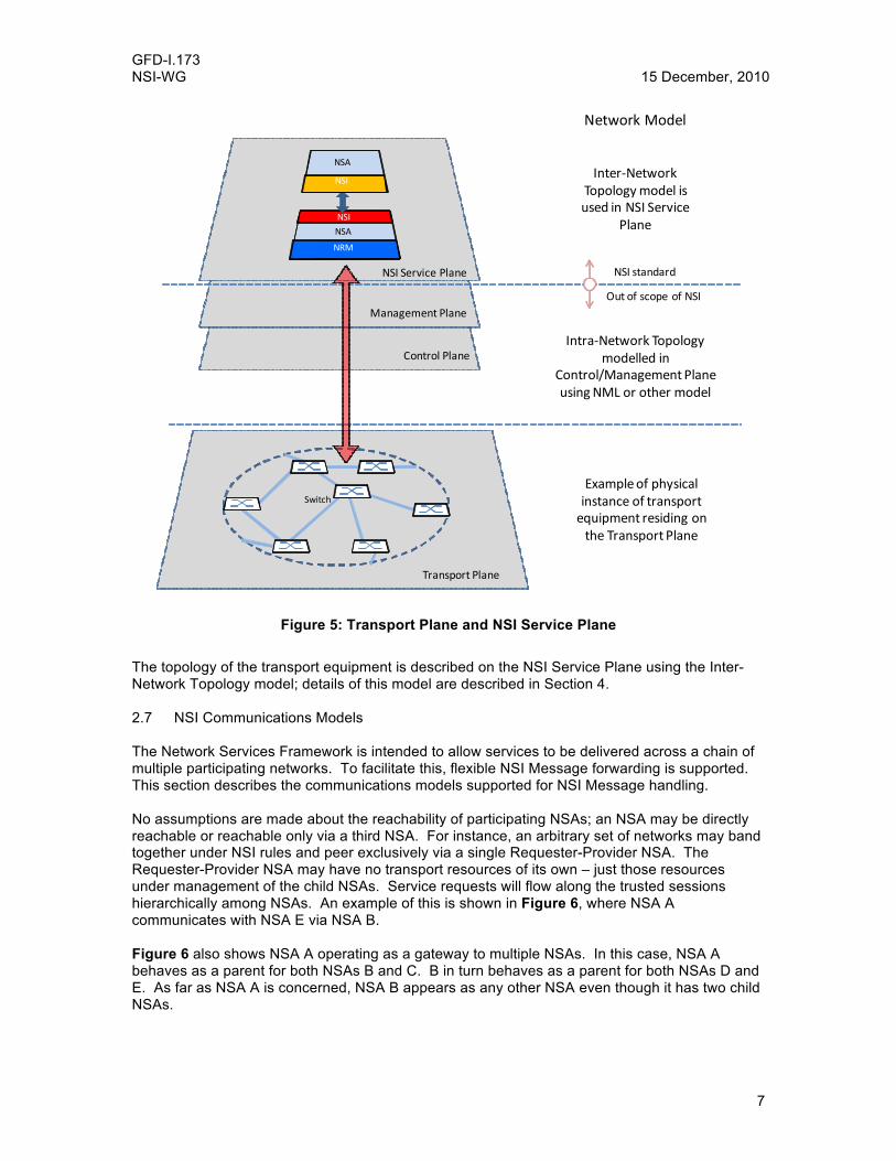
2.5 NSI Extensibility The Network Services Framework provides a common platform on which Network Services can be delivered. To achieve this aim, the NSI architecture is extensible; it inherently supports the ability to add new Network Services as they emerge. Examples of anticipated services include a topology service to distribute topology information and a connection monitoring service to collect connection status or performance data. Network Service Agents must support these services and functions in order to provide an integrated service. 2.6 The NSI Service Plane The Network Service Framework assigns the NSI to a notional NSI Service Plane. Here we define the Service Plane as including participating NSAs and the associated NSI sessions between these NSAs. The transport equipment (switches, X-connects, etc.) resides in the Transport Plane. This is depicted in Figure 5. In general, the NSI Service Plane relies on the capabilities of the Control Plane and/or Management Plane to effect changes in the Transport Plane, where the Control and Management Planes follow conventional definitions. The transport resources and the physical instance of the Connection reside on the Transport Plane.
GFD-I.173 NSI-WG 15 December, 2010
7
Inter-‐Network Topology model is used in NSI Service
Plane
Intra-‐Network Topology modelled in
Control/Management Plane using NML or other model
NSI Service Plane
NSA
NSA
NRM
NSI
NSI
Control Plane
Management Plane
Network Model
NSI standard
Out of scope of NSI
Transport Plane
Switch
Example of physical instance of transport equipment residing on the Transport Plane
Figure 5: Transport Plane and NSI Service Plane
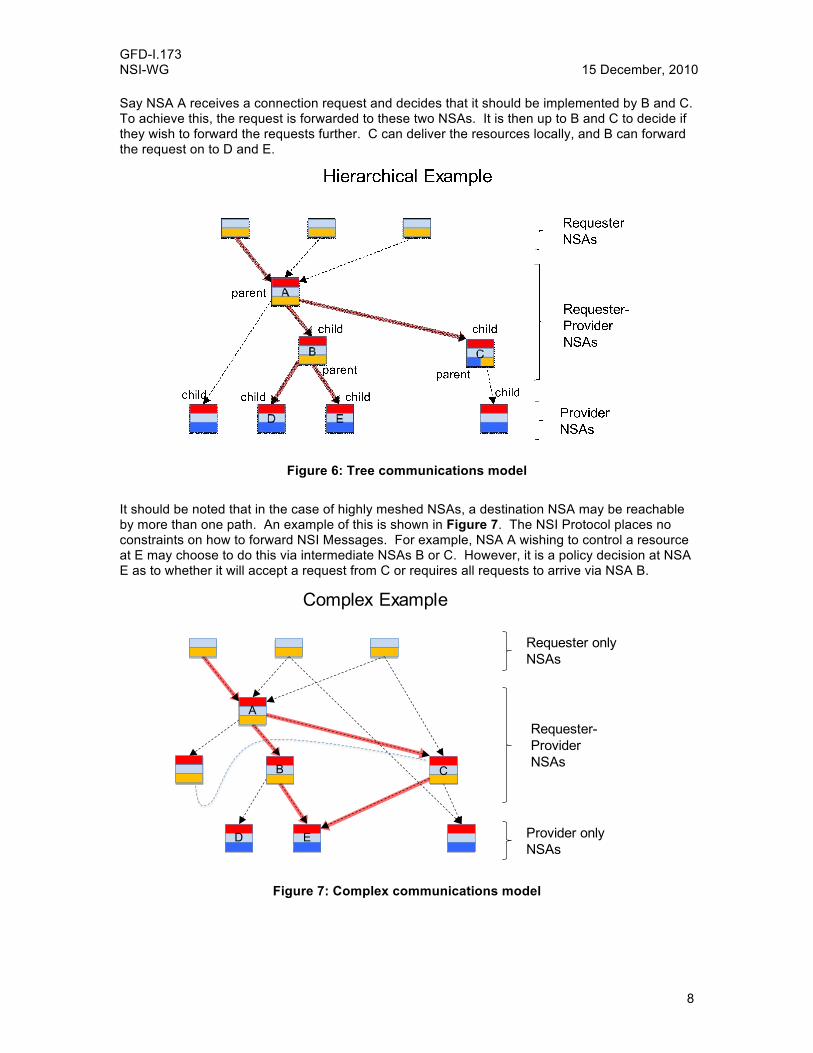
The topology of the transport equipment is described on the NSI Service Plane using the Inter-Network Topology model; details of this model are described in Section 4. 2.7 NSI Communications Models The Network Services Framework is intended to allow services to be delivered across a chain of multiple participating networks. To facilitate this, flexible NSI Message forwarding is supported. This section describes the communications models supported for NSI Message handling. No assumptions are made about the reachability of participating NSAs; an NSA may be directly reachable or reachable only via a third NSA. For instance, an arbitrary set of networks may band together under NSI rules and peer exclusively via a single Requester-Provider NSA. The Requester-Provider NSA may have no transport resources of its own – just those resources under management of the child NSAs. Service requests will flow along the trusted sessions hierarchically among NSAs. An example of this is shown in Figure 6, where NSA A communicates with NSA E via NSA B. Figure 6 also shows NSA A operating as a gateway to multiple NSAs. In this case, NSA A behaves as a parent for both NSAs B and C. B in turn behaves as a parent for both NSAs D and E. As far as NSA A is concerned, NSA B appears as any other NSA even though it has two child NSAs.
GFD-I.173 NSI-WG 15 December, 2010
8
Say NSA A receives a connection request and decides that it should be implemented by B and C. To achieve this, the request is forwarded to these two NSAs. It is then up to B and C to decide if they wish to forward the requests further. C can deliver the resources locally, and B can forward the request on to D and E.
Figure 6: Tree communications model
It should be noted that in the case of highly meshed NSAs, a destination NSA may be reachable by more than one path. An example of this is shown in Figure 7. The NSI Protocol places no constraints on how to forward NSI Messages. For example, NSA A wishing to control a resource at E may choose to do this via intermediate NSAs B or C. However, it is a policy decision at NSA E as to whether it will accept a request from C or requires all requests to arrive via NSA B.
Requester onlyNSAs
Requester-ProviderNSAs
Provider only NSAs
A
B
D E
Complex Example
C
Figure 7: Complex communications model
GFD-I.173 NSI-WG 15 December, 2010
9
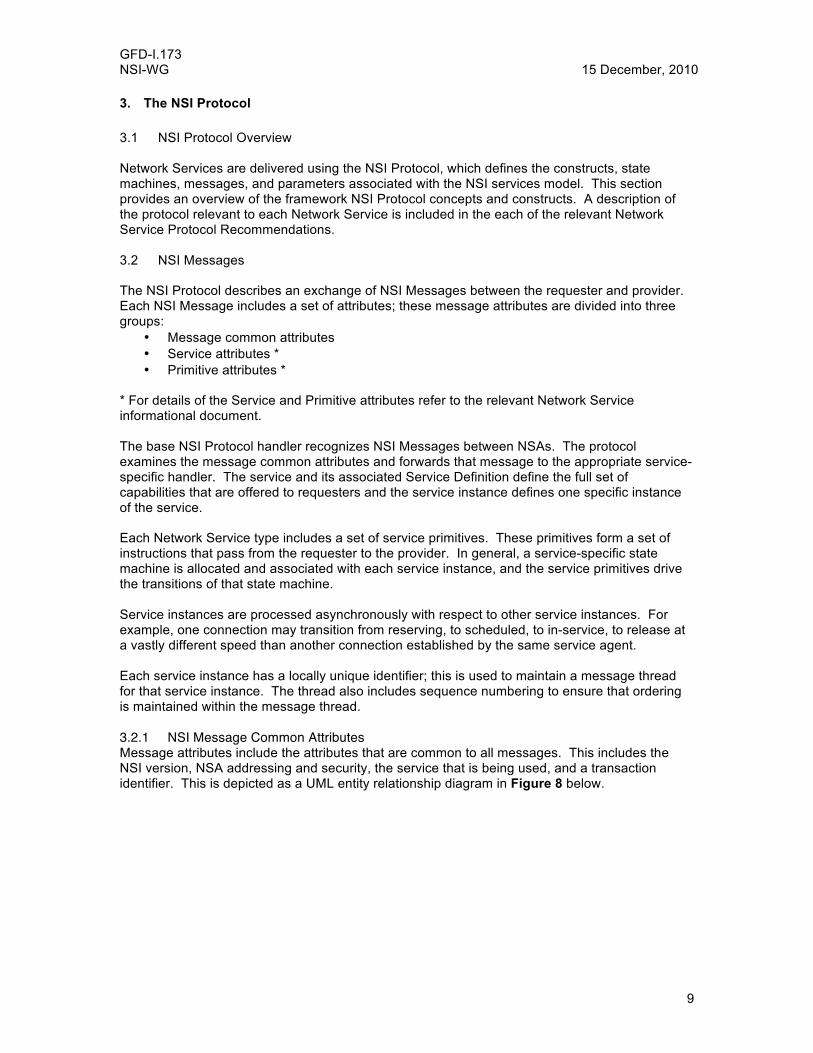
3. The NSI Protocol 3.1 NSI Protocol Overview Network Services are delivered using the NSI Protocol, which defines the constructs, state machines, messages, and parameters associated with the NSI services model. This section provides an overview of the framework NSI Protocol concepts and constructs. A description of the protocol relevant to each Network Service is included in the each of the relevant Network Service Protocol Recommendations. 3.2 NSI Messages The NSI Protocol describes an exchange of NSI Messages between the requester and provider. Each NSI Message includes a set of attributes; these message attributes are divided into three groups:
• Message common attributes • Service attributes * • Primitive attributes *
* For details of the Service and Primitive attributes refer to the relevant Network Service informational document. The base NSI Protocol handler recognizes NSI Messages between NSAs. The protocol examines the message common attributes and forwards that message to the appropriate service-specific handler. The service and its associated Service Definition define the full set of capabilities that are offered to requesters and the service instance defines one specific instance of the service. Each Network Service type includes a set of service primitives. These primitives form a set of instructions that pass from the requester to the provider. In general, a service-specific state machine is allocated and associated with each service instance, and the service primitives drive the transitions of that state machine. Service instances are processed asynchronously with respect to other service instances. For example, one connection may transition from reserving, to scheduled, to in-service, to release at a vastly different speed than another connection established by the same service agent. Each service instance has a locally unique identifier; this is used to maintain a message thread for that service instance. The thread also includes sequence numbering to ensure that ordering is maintained within the message thread. 3.2.1 NSI Message Common Attributes Message attributes include the attributes that are common to all messages. This includes the NSI version, NSA addressing and security, the service that is being used, and a transaction identifier. This is depicted as a UML entity relationship diagram in Figure 8 below.
GFD-I.173 NSI-WG 15 December, 2010
10
NSI Message
NSIversion
requesterNSA
providerNSA
ServiceType
messTransID
Message common attributes
Primitive attributes *
Service attributes *
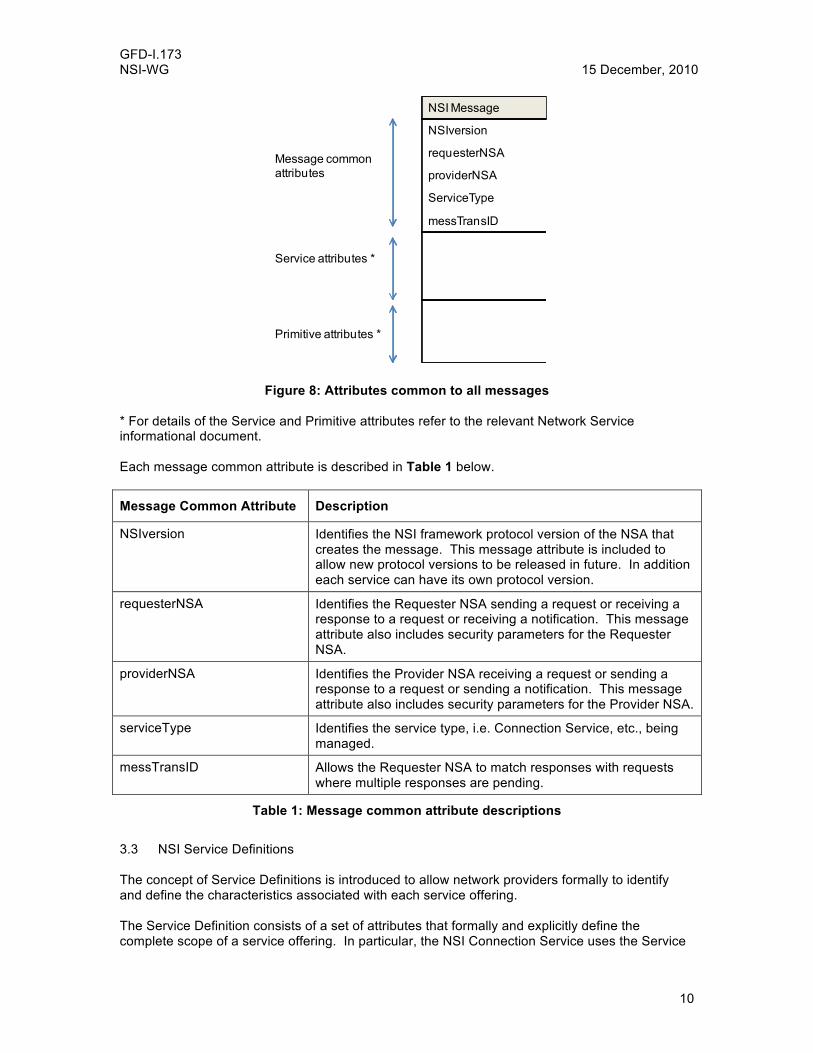
Figure 8: Attributes common to all messages * For details of the Service and Primitive attributes refer to the relevant Network Service informational document. Each message common attribute is described in Table 1 below.
Message Common Attribute Description
NSIversion Identifies the NSI framework protocol version of the NSA that creates the message. This message attribute is included to allow new protocol versions to be released in future. In addition each service can have its own protocol version.
requesterNSA Identifies the Requester NSA sending a request or receiving a response to a request or receiving a notification. This message attribute also includes security parameters for the Requester NSA.
providerNSA Identifies the Provider NSA receiving a request or sending a response to a request or sending a notification. This message attribute also includes security parameters for the Provider NSA.
serviceType Identifies the service type, i.e. Connection Service, etc., being managed.
messTransID Allows the Requester NSA to match responses with requests where multiple responses are pending.
Table 1: Message common attribute descriptions
3.3 NSI Service Definitions The concept of Service Definitions is introduced to allow network providers formally to identify and define the characteristics associated with each service offering. The Service Definition consists of a set of attributes that formally and explicitly define the complete scope of a service offering. In particular, the NSI Connection Service uses the Service
GFD-I.173 NSI-WG 15 December, 2010
11
Definition as a baseline set of parameters to determine the scope of the service that will be offered to requesters. The Service Definition specifies the set of service parameters that completely specify a service instance. For example, the Service Definition might identify “capacity”, “mtu_size”, and “maximum_frame_loss_rate” as three aspects of the service. The Service Definition also describes the range of allowed values for each service parameter, and a default value can be specified. In the context of the previous example, the range of allowed values for the “capacity” parameter may be 50 Mbps to 10 Gbps in increments of 150 Mbps. Or the “mtu_size” may be defined to be 1500 Bytes to 9000 Bytes with a default of 1500. The parameters in the Service Definition form a kind of template that must be filled at the creation of the service request with explicit values for all parameters of the service that do not have default values and optionally may provide values for parameters that have the default values specified. A service request is fully specified when all parameters associated with that service have been determined either explicitly by the user or implicitly by the default values found in the Service Definition. The fully specified request is then processed by the NSA and, if all service specifications can be satisfied, the service instance is reserved. (Note: a service instance identifier is created for each request, regardless of whether the request can ultimately be met. This allows the Provider NSA and the Requester NSA to process multiple requests asynchronously and in parallel and still be able to differentiate them.) The Service Definition is an integral component of the Network Service Framework in that it is key to vetting service requests against the multi-domain service offerings encountered along a candidate path. The Service Definition is a public document that can serve as both a human-readable guide to available service capabilities and a machine-readable file that can be processed by agents. 3.4 Temporal Aspects of NSI Services Services, in which resources are dynamically requested, reserved and provisioned, require the time information in a request to be interpreted in a common way. Any service that supports advance reservation must maintain its own real-time clock and it is necessary for the requester and provider clocks to be synchronized to a mutually acceptable granularity. In the case of a Connection Service, this granularity could be a fixed parameter of the Service Definition. When a Requester NSA seeks resources from a Provider NSA, a service instance is created and an identifier is assigned to that service instance. Then, according to the parameters of the request (i.e. its Service Definition), the Provider NSA identifies and reserves a set of available resources that satisfy the request and associates them with the instance. The resources are provisioned and released at some point on the temporal axis. The time information and signaling are used to specify the time boundary of the requested connection in-service period. It is the responsibility of the Provider NSA to attempt to deliver the resource as close to the start and end times as it is able. It should be noted that this may entail some uncertainty as typically the duration of the provisioning phase cannot be precisely predicted. 3.5 Trust and Authentication in the NSI Protocol This section describes the approach taken to trust and authentication in the NSI protocol; the detailed mechanisms for providing security and authentication are described in the NSI Protocol recommendation. Each NSA establishes NSI sessions with one or more other NSAs. An NSA will know for example that it is physically connected to its neighbor NSA; it may also have an identifier for that
GFD-I.173 NSI-WG 15 December, 2010
12
neighbor. Three types of trust are identified; types 1 and 2, NSA-NSA and service-to-service, are depicted in Figure 4. Type 3 relates to trust beyond a Requester/Provider NSA pair. 1. NSA-to-NSA relationship: The Requester and Provider NSAs establish a secure session
between Agents.
2. Service-to-service relationship: Secure sessions are established between the requester and provider parts of a Service. Standard methods for securing these sessions are described in the protocol document. These include:
• Relying on the NSA-to-NSA trusted session described in 1. above, and • Using separate ids and keys for the service-to-service trust.
3. Trust between non-adjacent NSAs: Attributes included in an NSI Message must be trusted by the NSI Message receiver. When the sender and receiver are Requester/Provider NSAs this trust can rely on the NSA-to-NSA trusted session. However, when an attribute received by an NSA is forwarded in an NSI Message to another NSA in the authorization sequence, a mechanism to provide trust between such non-adjacent NSAs is required.
3.6 NSI Service Plane Error Handling The Network Service Framework is based on a distributed, multi-agent architecture that is designed to handle error cases in such a way as to ensure predictable and deterministic behavior. This section describes the principles of error handling for the NSI Protocol. Network Service errors can be broadly categorized as soft or hard failures. A soft failure occurs when two NSAs lose communication with each other. A hard failure occurs if the NSA software restarts for any reason. Such failures may cause a loss of information about the state of services that were previously scheduled or are in process of being scheduled. The NSI Protocol includes mechanisms for recovering a consistent and predictable state after an anomaly has been detected. The following architectural principles guide error handling and recovery: • Handling of failures should result in deterministic behavior that is user centric and oriented
towards the service model. For example, a failure in the NSI Service Plane should not affect resources that are provisioned and active in the Transport Plane; a failure in the NSI Service Plane should not result in an incomplete service.
• Recovery of Transport and/or NSI Service Plane should not be reliant on external entities or
mechanisms. For example, an NSA recovering from a hard failure error condition will not depend on peer NSAs to reconstruct its state. This does not prevent a query function to validate the recovering NSA’s own state against that of its peers.
• Failures in the NSI Service Plane can result in NSA state faults. As depicted in Figure 9,
examples of NSI Service Plane errors include: losing communication with an NSA, losing communication with the transport network, corruption/crash in the platform, etc. These errors may result in service disruptions until the states can be synchronized, hence the NSI Protocol and state machine design should account for such scenarios.

GFD-I.173 NSI-WG 15 December, 2010
13
Context
NSA
NSI (provider)
NSANSI
(requester)
NSANSI
(requester)
NSANSI
(requester)
NSA
NSI (provider)
NSA
NSI (provider)
Communication Failure
Remote Agent Failure
Local Agent Failure
Figure 9: Local/remote failures within the context of a Provider NSA
Regardless of where the error originates, it is important that the NSA recover to a deterministic state. This means that both the user service state and the resource state should be consistent between NSAs. The hierarchical nature of the distributed model of servicing user requests allows each NSA to assume the role of a requester or provider. When NSI Service Plane failures occur, it is possible that an NSA will become entirely disconnected from other NSAs involved in a service instance. This scenario imposes a requirement on the NSA to have a relationship between its Requester and Provider NSA state machines to understand the impact of the failure on the service hierarchy and recover from it. The state machines should be designed so the outcome of a distributed failure ends with each state machine in a deterministic state.
4. Representing Network Resources 4.1 Describing Network Topologies A network transport topology is an object-oriented representation of network resources. The network topology may be used by functions such as path finding and resource reservation. For the purposes of the Network Services Framework, two topologies are identified: the Intra-Network and Inter-Network Topologies. Only the Inter-Network Topology is within the scope of the NSI protocol. The Intra-Network Topology refers to the topology of the resources within a network, where a network is defined as the group of network resources managed by a single network provider and a single NSA. The network provider is expected to have a pre-existing management or control system with its own method for network modeling. It is assumed that each NSA has access to its topology information, and no assumptions are made as to how this has been gathered or how it is represented. In other words, the method by which the Intra-Network Topology is represented is out of scope for the Network Service Framework. Many languages and models have been proposed to describe networks; some examples are OGF NML [1], and ITU-T G.805 [2]. It is expected that these and others could be used.

GFD-I.173 NSI-WG 15 December, 2010
14
The Inter-Network Topology refers to the topology of interconnected Networks. Here a Network is a topology object. The Inter-Network Topology is concerned with describing the way in which Networks are statically interconnected. It treats each Network as an aggregated set of Network capabilities with Edge Points. This Network Service Framework defines a representation of the Inter-Network Topology that should be used by the NSI. The Inter-Network Topology describes objects known as Service Termination Points (STPs), which identify the Edge Points on the Intra-Network Topology. These points represent resources (typically ports or virtual ports in the Intra-Network Topology); more than one STP can be associated with one Edge Point. A Network is a grouping of STPs that are available to an NSA. A Network also has a Transfer Function, which defines the connectivity between STPs; the Transfer Function describes the aggregated transport capabilities internal to a Network. Users can request resources from a Network via its associated NSA.
Network X
EP b
EP c
EP d
EP f
EP g
Inter-‐Network representation
EP e
Network Y
Intra-‐Network representation
TF TF
NSI standard
Out of scope of NSI
SDP -‐ Service Demarcation Point
STP -‐ Service Termination Points
Network -‐ Group of STPs
TF – Transfer function of aggregate internal network connectivity
Switch
Fibre
Switch
Transport equipment
STP:X:C/v1
EP h
STP:X:B/v1
STP:X:E/v3 STP:X:D/v1
STP:X:C/v2
STP:Y:G/v1
STP:Y:H/v1
STP:Y:F/v1
STP:Y:F/v2
SDP
SDP
EP – Edge PointLink Node
Figure 10: Inter-Network Topology
Each network provider can advertize a set of STPs to its local NSA. The NSA can then advertize these further to other NSAs. It is important to note that the provider may advertize both the STP and the Transfer Function. STPs remain capabilities until they have been instantiated by the NRM by instruction from the NSA. Details for using STPs are given in the next section. Figure 10 depicts an example of an Inter-Network Topology. It shows an example of how Networks and STPs can be used to describe an aggregated representation of a conventional Network model such as OGF-NML. As shown in Figure 10, more than one STP may be mapped to a single port in the Intra-Network Topology representation. The instances in the figure are STP:Y:F/v1 and STP:Y:F/v2, both being VLANs and associated with port F. This is discussed in more detail in the next section.
GFD-I.173 NSI-WG 15 December, 2010
15
The Inter-Network Topology as seen by a Requester-Provider NSA is aggregated and reported as an Intra-Network topology to parent NSAs. By aggregating the detailed transport topology into a single Network, or by grouping several Networks together to form an aggregated Network object, the global network topology may be reduced substantially. Successful implementation for a particular deployment will allow pathfinders to inexpensively compute coarse-grained path(s) between any pair of Networks. Each NSA along the candidate path is then consulted to reserve and confirm the resources. Note that it should not be assumed that a connection between Networks on the Transport Plane implies the existence of an NSI connection between associated NSAs; the Transport Plane connectivity and NSI Service Plane connectivity cannot be assumed to be congruent. 4.2 Using Service Termination Points The Network Service Framework includes the concept of Service Termination Points (STPs) and a pairing of STPs at a Service Demarcation Point (SDP). An STP names a topological location that is the ingress/egress point of a Network. For the purposes of the Connection Service, the demarcation point also forms the point at which Connections can be concatenated. This is the junction between the ingress of a Connection in one Network and the egress of a Connection in the next Network. 4.2.1 Service Termination Point A prerequisite for an STP is the existence of a physical connection into a Network. This pre-existing capability (typically made up of a physical port on a Network) can be advertized to an NSA. Note that the choice about which resources to advertize is subject to local policy. Once advertized, these capabilities may be used by the path-finding function of the NSA. STPs are advertized as “capabilities” to the NSA, i.e. they are not instantiated resources, but rather capabilities available for use in creating a Network Service. For example, this would include advertizing that a VLAN id 30 is available for use. When the NSA wishes to instantiate VLAN 30, this is signaled to the NRM and the VLAN 30 instance is created. Both STP capabilities and STP instances are represented in the NSI Service Plane with STP ids. An STP is a symbolic reference, i.e. it is an identifier which is comprised of a parsable alphanumeric string containing two components: 1) a Network identifier string in the higher order portion, and 2) a local STP identifier in the lower order portion. An STP must always resolve to a specific topological port object as defined in the Intra-Network Topology representation. An STP is a conceptual entity that maps to a specific resource in a network. STPs may be uni- or bi-directional. In the uni-directional case, the STP functions either as an ingress point or an egress point. This is defined by the flow polarity of the associated port, and which side of the junction is the user side, and which side is the network side. An STP capability can be represented as a group of possible STP instances, or a more flexible representation like a wildcard and constraints. For example, if there are 10 links these may be represented as a list (a, b, c, d, … j) or as a range (a-j). Note that this notation is used as an example only; refer to the NSI Protocol recommendation for details. A hierarchy of STPs may be represented using such groupings. For example, an STP group A may contain 10 STPs (a-j). This can be represented as: A/a, A/b … A/j. To support aggregation functions (Ethernet LAG or SDH virtual concatenation), two or more STPs can be aggregated. For example, if there are 10 links (1, 2, 3, …, 10) and any two of these links can be aggregated, there are 90 possible STP instances (1-2, 1-3, …, 9-10). The use of

GFD-I.173 NSI-WG 15 December, 2010
16
hierarchical STP groups is important for aggregation since only STPs within a group can be aggregated. Some examples are shown in Figure 11. 4.2.2 Service Demarcation Point Two adjacent networks agree on the connectivity capability between the two networks. The process for this agreement is out-of-scope for the NSI. When two STPs in adjacent networks with matching capabilities are paired, the resulting pairing forms a Service Demarcation Point (SDP). Further, SDPs may be grouped; this is depicted in Figure 11.
Network Y Network Z
STP:Y:A/v1
STP:Y:A/v2
STP:Y:A/v3
STP:Y:A/v4
STP:Z:A/v1
STP:Z:A/v2
STP:Z:A/w7
STP:Z:A/w8
STP:Y:B/c1
STP:Y:B/agg(c5,c5)
STP:Y:B/c20
STP:Z:B/d7
STP:Z:B/agg(d8,d9)
STP:Z:B/d20
Service Demarcation
Point
Figure 11: STP and SDP examples
Using the example shown in Figure 11, assume there are two Networks, Y and Z. The pairing process matches SDPs in each Network; these are then advertized as follows:
SDP A group: (STP:Y:A/v1, STP:Z:A/v1) (STP:Y:A/v2, STP:Z:A/v2) (STP:Y:A/v3, STP:Z:A/w7) (STP:Y:A/v4, STP:Z:A/w8)
SDP B group: (STP:Y:B/c1, STP:Z:B/d7 ) (STP:Y:B/agg(c5,c9), STP:Z:B/agg(d8,d9)) (STP:Y:B/c20, STP:Z:B/d20)
The NSI Inter-Network Topology model is composed of Networks interconnected by pairs of STPs. It should be noted that this topology is not a standard, nor does it imply that an NSI implementation must adopt any particular schema for its database in the code. 4.3 Managing Connections with the Intra-Network Topology

GFD-I.173 NSI-WG 15 December, 2010
17
The Network Services Framework supports many services. The first of these is the Connection Service. The purpose of this service is to manage Connections. A Connection is defined to be the connectivity between STPs. Connections in two networks may be concatenated at Service Demarcation Points (STP pairs) to create longer Connections. Once instantiated, an STP may have properties such as a framing, bandwidth and a VLAN id. Some of these properties may reflect the requirements specified in the Service Definition. Labeling (such as fiber id, wavelength, VLAN id) and aggregation (i.e. combining multiple switch ports) can be modeled as a property of an STP. A Service Demarcation Point can function as both an ingress point on one side and an egress point on the other. Two such connections that share a single Service Demarcation Point in this way are said to be concatenated. These two concatenated connections then appear to the user payload as a single end-to-end transport plane data-path. In this way a Service Demarcation Point becomes an intermediate transit point of a path or connection, i.e. a routing point through which the connection must pass. Figure 12 depicts an example of a Connection Service between hosts, one internal to Network W and the other attached to an STP of Network Z. The Connection is created by requesting a Connection in Networks X, Y and Z. In Network W, the host is internally connected (i.e. not advertized to the NSA). In Network Z, the host is connected to an STP; it may be reached directly by using an NSI connection to STP k.
EP a
Node
EP b
EP c
EP d
EP fNode
EP g
EP h
Inter-‐Network representation of network resources
EP e
Intra-‐network representation of network resources
STP -‐ Service Termination PointTF -‐ Transfer FunctionSDP -‐ Service Demarcation Point
Host
STP a/STP b
Network X
STP eSTP d
STP gNetwork W
NetworkY
STP c/STP f
TFTF
Dynamic Connection
STP h/STP j
Network W Network Z
EP j
EP k
Host
STP k
SDP
SDP
SDP
EP -‐ Edge pointLink Node
Figure 12: Representing Connections
Using the example in Figure 12, to request the shown Inter-Network connection, the NSA will request: • To network X: instantiate a connection between STPs: X:b and X:c
GFD-I.173 NSI-WG 15 December, 2010
18
• To network Y: instantiate a connection between STPs: Y:f and Y:h • To network Z: instantiate a connection between STPs: Z:j and Z:k Each NSA looks up its own calendar and checks the availability of the STPs. Note that the NSAs for Networks X, Y and Z may have differing availability information in their local calendars.
5. Summary
The Network Services Framework defines several key architectural elements required to request and build services within the NSI Service Plane. The framework describes an environment within which Network objects are defined as manageable resources. Within the framework, these network resources can be selected, allocated, interrogated, and manipulated by software agents on behalf of requesting users.
Federated Network Services are delivered by bring together the capabilities of participating providers. To manage federated services, a range of network-related functional capabilities such as topology sharing, path finding, resource reservation, hardware provisioning, and other ancillary services and functions are required. These may be formalized in future versions of the NSI protocol.
A suite of informational documents and recommendations define the NSI protocol. In addition to the Network Services Framework document, each Network Service, such as a Connection Service, is defined in its own information document and counterpart protocol recommendation.
6. Contributors Joan A. García-Espín, I2CAT Chin Guok, ESNET Radek Krzywania, PSNC Tomohiro Kudoh, AIST John MacAuley, SURFnet Takahiro Miyamoto, KDDI R&D Laboratories Inder Monga, ESnet Guy Roberts, DANTE Jerry Sobieski, NORDUnet Sebastien Soudan, Laboratoire de l'Informatique du Parallèlisme John Vollbrecht, Internet2 Freek Dijkstra, SARA Jeroen van der Ham, University of Amsterdam
7. Glossary Connection A Connection is a conduit that transparently moves user
information between STPs across a Network. A Connection has a set of properties (for instance, capacity, or authorization, or start time). These properties, and their allowed range of values, are defined by a Service Definition. A Connection instance on the Transport Plane is identified by a connection identifier exchanged on the NSI Service Plane. Connections are uni-directional.
Connection Service A Connection Service is a service that allows a Requester NSA to request and manage a Connection from a Provider NSA.
GFD-I.173 NSI-WG 15 December, 2010
19
Control/Management Plane The Control Plane and Management Plane are not defined in this document, but follow common usage.
Edge Point A network resource that resides at the boundary of an Intra-Network Topology. This may include, for example, a connector on a distribution frame, a port on an Ethernet switch, or a connector at the end of a fiber.
Inter-Network Topology This is a topological description of a set of Networks and their Transfer Functions, and the connectivity between Networks.
Intra-Network Topology This is a topological description that describes the connectivity internal to a Network. The level of detail that a provider chooses to advertize in the Intra-Network Topology is the choice of the provider.
Network A Network is an Inter-Network Topology object that describes a set of STPs with a Transfer Function between STPs.
Network Resource Manager The Network Resource Manager owns a set of transport resources and has ultimate responsibility for authorizing and managing the use of these resources. Each NRM is always associated with a single NSA.
Network Services Network Services are the services offered by an NSA. Each NSA will support one or more Network Service(s).
Network Service Agent The Network Service Agent is a concrete piece of software that sends and receives NSI Messages. The NSA includes a set of capabilities that allow Network Services to be delivered.
Network Service Interface The Network Service Interface is the interface between Requester NSAs and Provider NSAs. The NSI Protocol is exchanged over the Network Service Interface.
Network Services Framework The Network Services Framework describes an NSI message-based platform capable of supporting a range of Network Services.
NSI Message An NSI Message is a structured unit of data sent between a Requester NSA and a Provider NSA.
NSI Protocol The NSI Protocol is the set of messages and associated attributes exchanged between Requester and Provider NSAs and the interactions and use of these messages.
Network Service Agent An NSA acts in one of three possible roles relative to a particular instance of an NSI. When an NSA requests a service, it is called a Requester NSA. When an NSA realizes a service, it is called a Provider NSA. A particular NSA may take on both requester and provider roles, in which case it is referred to as a Requeter-ProviderNSA.
Service Definition The Service Definition consists of a set of attributes that formally and explicitly define the complete scope of a service offering. Each provider defines its service with an SD, each request

GFD-I.173 NSI-WG 15 December, 2010
20
identifies requirements in terms of SD attributes, and each Connection has an associated Service Definition instance.
Service Demarcation Point Service Demarcation Points (SDPs) consist of a pair of STPs on adjacent Networks that are attached to each other.
Service Termination Point Service Termination Points (STPs) identify the Edge Points in the Intra-Network Topology.
NSI Service Plane The NSI Service Plane is a plane in which services are requested and managed; these services include the Network Service. The NSI Service Plane contains a set of Network Service Agents communicating using Network Service Interfaces.
Transfer Function The Transfer Function is a matrix that describes the transport capabilities between STPs.
Transport Plane The Transport Plane contains the set of transport equipment and associated resources that carry user data through the network.
8. Intellectual Property Statement The OGF takes no position regarding the validity or scope of any intellectual property or other rights that might be claimed to pertain to the implementation or use of the technology described in this document or the extent to which any license under such rights might or might not be available; neither does it represent that it has made any effort to identify any such rights. Copies of claims of rights made available for publication and any assurances of licenses to be made available, or the result of an attempt made to obtain a general license or permission for the use of such proprietary rights by implementers or users of this specification can be obtained from the OGF Secretariat. The OGF invites any interested party to bring to its attention any copyrights, patents or patent applications, or other proprietary rights which may cover technology that may be required to practice this recommendation. Please address the information to the OGF Executive Director.
9. Disclaimer This document and the information contained herein is provided on an “As Is” basis and the OGF disclaims all warranties, express or implied, including but not limited to any warranty that the use of the information herein will not infringe any rights or any implied warranties of merchantability or fitness for a particular purpose.
10. Full Copyright Notice Copyright (C) Open Grid Forum (2008-2010). All Rights Reserved. This document and translations of it may be copied and furnished to others, and derivative works that comment on or otherwise explain it or assist in its implementation may be prepared, copied, published and distributed, in whole or in part, without restriction of any kind, provided that the above copyright notice and this paragraph are included on all such copies and derivative works. However, this document itself may not be modified in any way, such as by removing the copyright notice or references to the OGF or other organizations, except as needed for the purpose of developing Grid Recommendations in which case the procedures for copyrights defined in the
GFD-I.173 NSI-WG 15 December, 2010
21
OGF Document process must be followed, or as required to translate it into languages other than English. The limited permissions granted above are perpetual and will not be revoked by the OGF or its successors or assignees.
11. References [1] OGF, NML-WG: GFD-I.165: Network topology descriptions in hybrid networks [2] ITU-T, G.805: Generic functional architecture of transport networks [3] ITU-T G.8080/Y.1304: Architecture for the automatically switched optical network (ASON)