Network Protocol Configuration - FS · Network Protocol Configuration - 1 - Chapter 1 Configuring...
43
Network Protocol Configuration Table of Contents www.fs.com
Transcript of Network Protocol Configuration - FS · Network Protocol Configuration - 1 - Chapter 1 Configuring...

Network Protocol Configuration
Table of Contents
www.fs.com

Table of Contents
- I -
Table of Contents
Chapter 1 Configuring IP Addressing ..................................................................................................1
1.1 IP Introduction ........................................................................................................................1
1.1.1 IP .................................................................................................................................1
1.1.2 IP Routing Protocol .....................................................................................................1
1.2 Configuring IP Address Task List ...........................................................................................2
1.3 Configuring IP Address ..........................................................................................................3
1.3.1 Configuring IP Address at Network Interface ..............................................................3
1.3.2 Configuring Multiple IP Addresses on Network Interface ............................................4
1.3.3 Configuring Address Resolution ..................................................................................4
1.3.4 Configuring Routing Process ......................................................................................6
1.3.5 Configuring Broadcast Message Handling ..................................................................7
1.3.6 Detecting and Maintaining IP Addressing ...................................................................8
1.4 IP Addressing Example ..........................................................................................................8
Chapter 2 Configuring NAT .................................................................................................................9
2.1 Introduction ............................................................................................................................9
2.1.1 NAT Application ...........................................................................................................9
2.1.2 NAT Advantage ...........................................................................................................9
2.1.3 NAT Terms ................................................................................................................ 10
2.1.4 NAT Regulation Matching Order .............................................................................. 10
2.2 NAT Configuration Task List ................................................................................................. 11
2.3 NAT Configuration Task ....................................................................................................... 11
2.3.1 Translating Inside Source Address ........................................................................... 11
2.3.2 Reloading Inside Global Address ............................................................................. 13
2.3.3 Translating Overlapping Addresses ......................................................................... 15
2.3.4 Providing TCP Load Balance ................................................................................... 17
2.3.5 Changing Translation Timeout Time and Limiting the Number of Connections ....... 18
2.3.6 Monitoring and Maintaining NAT .............................................................................. 19
2.4 NAT Configuration Example ............................................................................................... 20
2.4.1 Dynamic Inside Source Transfer Example ............................................................... 20
2.4.2 Inside Global Address Reloading Example .............................................................. 20
2.4.3 Example to overlapping address transfer ................................................................ 21
2.4.4 TCP Load Distribution Example ............................................................................... 21
Chapter 3 Configuring DHCP ........................................................................................................... 23
3.1 Introduction ......................................................................................................................... 23
3.1.1 DHCP Applications ................................................................................................... 23
3.1.2 DHCP Advantages ................................................................................................... 23
3.1.3 DHCP Terminology ................................................................................................... 24
3.2 Configuring DHCP Client .................................................................................................... 24
3.2.1 DHCP Client Configuration Tasks ............................................................................ 24
3.2.2 DHCP Client Configuration Tasks ............................................................................ 24
3.2.3 DHCP Client Configuration Example ....................................................................... 26
www.fs.com

Table of Contents
- II -
3.3 Configuring DHCP Server ................................................................................................... 26
3.3.1 DHCP Server Configuration Tasks ........................................................................... 26
3.3.2 Configuring DHCP Server ........................................................................................ 26
3.3.3 DHCP Server Configuration Example ...................................................................... 29
Chapter 4 IP Service Configuration .................................................................................................. 30
4.1 Configuring IP Service ........................................................................................................ 30
4.1.1 Managing IP Connection .......................................................................................... 30
4.1.2 Configuring Performance Parameters ..................................................................... 33
4.1.3 Detecting and Maintaining IP Network ..................................................................... 34
4.2 Configuring Access List ...................................................................................................... 35
4.2.1 Filtering IP Message ................................................................................................ 35
4.2.2 Creating Standard and Extensible IP Access List .................................................... 36
4.2.3 Applying the Access List to the Interface ................................................................. 37
4.2.4 Extensible Access List Example .............................................................................. 37
4.3 Configuring IP Access List Based on Physical Port ............................................................ 38
4.3.1 Filtering IP Message ................................................................................................ 38
4.3.2 Filtering IP Message ................................................................................................ 38
4.3.3 Creating Standard and Extensible IP Access List .................................................... 38
4.3.4 Applying the Access List to the Interface ................................................................. 39
4.3.5 Extensible Access List Example .............................................................................. 40
www.fs.com

Network Protocol Configuration
- 1 -
Chapter 1 Configuring IP Addressing
1.1 IP Introduction
1.1.1 IP
Internet Protocol (IP) is a protocol in the network to exchange data in the text form. IP has the functions such as addressing, fragmenting, regrouping and multiplexing. Other IP protocols (IP protocol cluster) are based on IP. As a protocol working on the network layer, IP contains addressing information and control information which are used for routing.
Transmission Control Protocol (TCP) is also based on IP. TCP is a connection-oriented protocol which regulates the format of the data and information in data transmission. TCP also gives the method to acknowledge data is successfully reached. TCP allows multiple applications in a system to communicate simultaneously because it can send received data to each of the applications respectively.
The IP addressing, such as Address Resolution Protocol, are to be described in section 1.3 “Configuring IP Addressing.” IP services such as ICMP, HSRP, IP statistics and performance parameters are to be described in Chapter 4 “Configuring IP Services.”
1.1.2 IP Routing Protocol
Our routing switch supports multiple IP routing dynamic protocols, which will be described in the introduction of each protocol.
IP routing protocols are divided into two groups: Interior Gateway Routing Protocol (IGRP) and Exterior Gateway Routing Protocol (EGRP). Our routing switch supports RIP, OSPF, BGP and BEIGRP. You can configure RIP, OSPF, BGP and BEIGRP respectively according to your requirements. Our switch also supports the process that is to configure multiple routing protocols simultaneously, a random number of OSPF processes (if memory can be distributed), a BGP process, a RIP process and a random number of BEIGRP processes. You can run the redistribute command to
redistribute the routes of other routing protocols to the database of current routing processes, connecting the routes of multiple protocol processes.
To configure IP dynamic routing protocols, you must first configure relevant processes, make relevant network ports interact with dynamic routing processes, and then designate routing processes to be started up on the ports. To do this, you may check configuration steps in configuration command documents.
1. Choosing routing protocol
It is a complex procedure to choose routing protocol. When you choose the routing protocol, consider the following items:
www.fs.com

Network Protocol Configuration
- 2 -
Size and complexity of the network
Whether the length-various network need be supported
Network traffic
Safety requirements
Reliability requirements
Strategy
Others
Details of the above items are not described in the section. We just want to remind you that your network requirements must be satisfied when you choose the routing protocols.
2. IGRP
Interior Gateway Routing Protocol (IGRP) is used for network targets in an autonomous system. All IP IGRPs must be connected with networks when they are started up. Each routing process monitors the update message from other routing switches in the network and broadcasts its routing message in the network at the same time. The IGRPs that our routing switches support include:
RIP
OSPF
BEIGRP
3. EGRP
Exterior Gateway Routing Protocol (EGRP) is used to exchange routing information between different autonomonous systems. Neighbors to exchange routes, reachable network and local autonomonous system number generally need to be configured. The EGRP protocol that our switch supports is BGP.
1.2 Configuring IP Address Task List
An essential and mandatory requirement for IP configuration is to configure the IP address on the network interface of the routing switch. Only in this case can the network interface be activated, and the IP address can communicate with other systems. At the same time, you need to confirm the IP network mask.
To configure the IP addressing, you need to finish the following tasks, among which the first task is mandatory and others are optional.
For creating IP addressing in the network, refer to section 1.4 “IP Addressing Example.”
Followed is an IP address configuration task list:
www.fs.com

Network Protocol Configuration
- 3 -
Configuring IP address at the network interface
Configuring multiple IP addresses at the network interface
Configuring address resolution
Configuring routing process
Configuring broadcast text management
Detecting and maintaining IP addressing
1.3 Configuring IP Address
1.3.1 Configuring IP Address at Network Interface
The IP address determines the destination where the IP message is sent to. Some IP special addresses are reserved and they cannot be used as the host IP address or network address. Table 1 lists the range of IP addresses, reserved IP addresses and available IP addresses.
Type Address or Range State
A
0.0.0.0
1.0.0.0 to 126.0.0.0
127.0.0.0
Reserved
Available
Reserved
B 128.0.0.0 to 191.254.0.0
191.255.0.0
Available
Reserved
C
192.0.0.0
192.0.1.0 to 223.255.254
223.255.255.0
Reserved
Available
Reserved
D 224.0.0.0 to 239.255.255.255 Multicast address
E 240.0.0.0 to 255.255.255.254
255.255.255.255
Reserved
Broadcast
The official description of the IP address is in RFC 1166 “Internet Digit”. You can contact the Internet service provider.
An interface has only one primary IP address. Run the following command in interface configuration mode to configure the primary IP address and network mask of the network interface:
Run… To…
ip address ip-address mask Configure the main IP address of the
interface.
The mask is a part of the IP address, representing the network.
Note:
www.fs.com

Network Protocol Configuration
- 4 -
Our switches only support masks which are continuously set from the highest byte according to the network character order.
1.3.2 Configuring Multiple IP Addresses on Network Interface
Each interface can possess multiple IP addresses, including a primary IP address and multiple subordinate IP addresses. You need to configure the subordinate IP addresses in the following two cases:
If IP addresses in a network segment are insufficient.
For example, there are only 254 available IP addresses in a certain logical subnet, however, 300 hosts are needed to connect the physical network. In this case, you can configure the subordinate IP address on the switch or the server, enabling two logical subnets to use the same physical subnet. Most of early-stage networks which are based on the layer-2 bridge are not divided into multiple subnets. You can divide the early-stage network into multiple route-based subnets by correctly using the subordinate IP addresses. Through the configured subordinate IP addresses, the routing switch in the network can know multiple subnets that connect the same physical network.
If two subnets in one network are physically separated by another network.
In this case, you can take the address of the network as the subordinate IP address. Therefore, two subnets in a logical network that are physically separated, therefore, are logically connected together.
Note:
If you configure a subordinate address for a routing switch in a network segment, you need to do this for other routing switches in the same network segment.
Run the following command in interface configuration mode to configure multiple IP addresses on the network interface.
Run… To…
ip address ip-address mask secondary Configure multiple IP addresses on the
network interface.
Note:
When the IP routing protocol is used to send the route update information, subordinate IP addresses may be treated in different ways.
1.3.3 Configuring Address Resolution
IP can realize functions such as IP address resolution control. The following sections show how to configure address resolution:
1. Creating address resolution
An IP device may have two addresses: local address (local network segment or device uniquely identified by LAN) and network address (representing the network where the device is located). The local address is the address of the link layer because the local
www.fs.com

Network Protocol Configuration
- 5 -
address is contained in the message header at the link layer, and is read and used by devices at the link layer. The professionalists always call it as the MAC address. This is because the MAC sub layer in the link layer is used to process addresses.
For example, if you want your host to communicate with a device on Ethernet, you must know the 48-bit MAC address of the device or the local address of the link layer. The process on how to obtain the local address of the link layer from the IP address is called as Address Resolution Protocol (ARP). The process on how to obtain the IP address from the local address of the link layer is called as Reverse Address Resolution (RARP).
Our system adopts address resolution in two types: ARP and proxy ARP. The ARP and proxy ARP are defined in RFC 860 and 1027 respectively.
ARP is used to map IP addresses to media or MAC address. When the IP address is known, ARP will find the corresponding MAC address. When the MAC address is known, the mapping relationship between IP address and MAC address is saved in ARP cache for rapid access. The IP message is then packaged in the message at the link layer and at last is sent to the network.
Defining a static ARP cache
ARP and other address resolution protocols provide a dynamic mappingbetween IP address and MAC address. The static ARP cache item is generallynot required because most hosts support dynamic address resolution. You candefine it in global configuration mode if necessary. The system utilizes the staticARP cache item to translate the 32-bit IP address into a 48-bit MAC address.Additionally, you can specify the routing switch to respond to the ARP request forother hosts.
You can set the active period for the ARP items if you do not want the ARP itemto exist permanently. The following two types show how to configure themapping between the static IP address and the MAC address.
Run one of the following commands in global configuration mode:
Run… To…
arp ip-address hardware-address Globally map an IP address to a MAC
address in the ARP cache.
arp ip-address hardware-address alias Specify the routing switch to respond to the
ARP request of the designated IP address
through the MAC address of the routing
switch.
Run the following command in interface configuration mode:
Run… To…
arp timeout seconds Set the timeout time of the ARP cache item
in the ARP cache.
Run show interfaces to display the ARP timeout time of the designated interface. Run the show arp to check the content of the ARP cache. Run clear arp-cache to delete all items in the ARP cache.
Activating proxy ARP
The system uses the proxy ARP (defined by RFC 1027) to obtain the host’sMAC address on other networks for the hosts without corresponding routes. Forexample, when the routing switch receives an ARP request and finds that thesource host and the destination host are not connected to the same interfaceand all the routes that the routing switch reaches the destination host are not
www.fs.com

Network Protocol Configuration
- 6 -
through the interface that receives the ARP request, it will send a proxy ARP response that contains its address of the link layer. The source host then sends the message to the routing switch and the switch forwards it to the destination host. The proxy ARP is activates by default.
To activate the proxy ARP, run the following command in interface configuration mode:
Run… To…
ip proxy-arp Activate the proxy ARP on the interface.
Configuring free ARP function
The switch can know whether the IP addresses of other devices collide with itsIP address by sending free ARP message. The source IP address and thedestination IP address contained by free ARP message are both the localaddress of the switch. The source MAC address of the message is the localMAC address.
The switch processes free ARP message by default. When the switch receivesfree ARP message from a device and finds that the IP address contained in themessage collide with its own IP address, it will return an ARP answer to thedevice, informing the device that the IP addresses collide with each other. At thesame time, the switch will inform users by logs that IP addresses collide.
The switch’s function to send free ARP message is disabled by default. Run thefollowing commands to configure the free ARP function on the port of the switch:
Run… To…
arp send-gratuitous Start up free ARP message transmission on
the interface.
arp send-gratuitous interval value Set the interval for sending free ARP
message on the interface.
The default value is 120 seconds.
2. Mapping host name to IP addres
Any IP address can correspond to a host name. The system stores a hostname-to-address mapping cache that you can telnet or ping.
Run the following command in global configuration mode to specify a mapping between host name and IP address:
Run… To…
ip host name address Statically map the host name to the IP
address.
1.3.4 Configuring Routing Process
You can configure one or multiple routing protocols according to your actual network requirements. The routing protocol provides information about the network topology. The details about configuring IP routing protocols such as BGP, RIP and OSPF are shown in the following sections.
www.fs.com

Network Protocol Configuration
- 7 -
1.3.5 Configuring Broadcast Message Handling
The destination addresses of the broadcast message are all the hosts on a physical network. The host can identify the broadcast message through special address. Some protocols, including some important Internet protocols, frequently use the broadcast message. One primary task of the IP network administrator is to control the broadcast message. The system supports the directed broadcast, that is, the broadcast of designated network. The system does not support the broadcast of all subnets in a network.
Some early-stage IP’s do not adopt the current broadcast address standard. The broadcast address adopted by these IP’s is represented completely by the number “0”. The system can simultaneously identify and receive message of the two types.
1. Allowing translating from directed broadcast to physical broadcast
The directed IP broadcast message will be dropped by default, preventing the switch from attacking by message “service rejected”.
You can activate the function of forwarding directed IP broadcast on the interface where the directed broadcast is transformed to the physical message. If the forwarding function is activated, all the directed broadcast message of the network that connects the interface will be forwarded to the interface. The message then will be sent as the physical broadcast message.
You can designate an access table to control the forwarding of broadcast message. After the access table is specified, only IP message that the access table allows can be transformed from the directed broadcast to the physical broadcast.
Run the following command in interface configuration mode to activate the forwarding of the directed broadcast.
Run… To…
ip directed-broadcast [access-list-name] Allow the translation from the directed broadcast
to the physical broadcast on the interface.
2. Forwarding UDP broadcast message
Sometimes, the host uses the UDP broadcast message to determine information about the address, configuration and name, and so on. If the network where the host is located has no corresponding server to forward the UDP message, the host cannot receive any of the UDP message. To solve the problem, you can do some configuration on the corresponding interface to forward some types of broadcast message to an assistant address. You can configure multiple assistant addresses for an interface.
You can designate a UDP destination port to decide which UDP message is to be forwarded. Currently, the default forwarding destination port of the system is port 137.
Run the following command in interface configuration mode to allow message forwarding and to specify the destination address:
Run… To…
ip helper-address address Allow to forward the UDP broadcast message
www.fs.com

Network Protocol Configuration
- 8 -
and to specify the destination address.
Run the following command in global configuration mode to specify protocols to be forwarded:
Run… To…
ip forward-protocol udp [port] Specify which interfaces’ UDP protocols will be
forwarded.
1.3.6 Detecting and Maintaining IP Addressing
Perform the following operations to detect and maintain the network:
1. Clearing cache, list and database
You can clear all content in a cache, list or the database. When you think some content is ineffective, you can clear it.
Run the following command in management mode to clear the cache, list and database:
Run… To…
clear arp-cache Clear the IP ARP cache.
2. Displaying statistics data about system and network
The system can display designated statistics data, such as IP routing table, cache and database. All such information helps you know the usage of the systematic resources and solve network problems. The system also can display the reachability of the port and the routes that the message takes when the message runs in the network.
All relative operations are listed in the following table. For how to use these commands, refer to Chapter “IP Addressing Commands”.
Run the following commands in management mode:
Run… To…
show arp Display content in the ARP table.
show hosts Display the cache table about hostname-to-IP
mapping.
show ip interface [type number] Display the interface state.
show ip route [protocol] Display the current state of the routing table.
ping {host | address} Test the reachability of the network node.
1.4 IP Addressing Example
The following case shows how to configure the IP address on interface VLAN 11.
interface vlan 11
ip address 202.96.2.3 255.255.255.0
www.fs.com

Network Protocol Configuration
- 9 -
Chapter 2 Configuring NAT
2.1 Introduction
The Internet faces two key problems: insufficient IP address space and route measurement. Network Address Translation (NAT) is an attribute. You can find that a group of IP networks with this attribute use different IP address spaces, but you cannot find the actual address space used by the group of networks. By transforming these addresses to the address spaces that can be globally routed, NAT permits an organization without global routing addresses to connect the Internet. NAT also permits good recoding strategy to change the service providers for the organizations or to automatically code to the CIDR module. NAT will be described in RFC 1631.
2.1.1 NAT Application
Main NAT applications are shown as follows:
All hosts need to connect to the Internet, but no all hosts have a unique global IPaddress. NAT enables unregistered networks with private IP addresses toconnect the Internet. NAT are always configured at the routing switch betweeninside network and Internet. Before sending message to the Internet, NATtransfers the inside local address to the unique global IP address.
The inside address has to be modified. You can transform the address by usingNAT without too much time.
The basic TCP transmission load balance need be realized. You can map asingle global IP address to multiple IP addresses using TCP load distributioncharacteristic.
As a resolution for connection problems, NAT can be used when relatively fewhosts in an inside network communicate with the Internet. In this case, the IPaddresses of few hosts will be transformed to a unique global IP address whenthey communicate with the Internet. These addresses can be reused when theyare not used any more.
2.1.2 NAT Advantage
An obvious advantage of NAT is that you can perform configuration without modifying host or switch. As said above, NAT is useless if many hosts in a single-connection domain communicate with the outside. What’s more, the NAT device is not suitable to translate the embedded IP address. These applications cannot work transparently or completely (without translation) pass through a NAT device. NAT hides the identifier of the host, which may be an advantage or a shortcoming.
The router configured with NAT has at least one inside interface and one outside interface. In typical case, NAT is configured at the router between the single-connection domain and the backbone domain. When a message is leaving the single-connection domain, NAT transforms the effective local address to a unique
www.fs.com

Network Protocol Configuration
- 10 -
global address. When the message reaches the domain, NAT transforms the unique global address to the local address. If multiple interfaces exist, each NAT must have the same the transfer table. If no address is available, the software cannot distribute an address and NAT will drop the message and returns an ICMP message indicating the host cannot be reached.
The switch with NAT configured should not publish the local network. However, the routing information that NAT receives from the outside can be published in the single-connection domain.
2.1.3 NAT Terms
As said above, the term “inside” means those networks which are possessed by organizations and have to be transformed. In this domain, the host has an address in one address space. At the outside, the host will possess an address in another address space when the NAT is configured. The first address space means the local address space, while the second address space means the global address space.
Similarly, the term “outside” means the network that the single network connects, generally out of control of an organization. The addresses of the hosts in the outside network need to translate a certain address and may be classified into two types of addresses: local address and global address.
NAT uses the following definitions:
Inside local address: IP address that is allocated to a host in the inside network.The address may not be the legal IP address distributed by Network InformationCenter (NIC) or service provider (SP).
Inside global address: legal IP address distributed by NIC or SP, describing oneor multiple IP addresses for the outside network.
Outside local address: IP address of the outside host that appears in the insidenetwork. It may be illegal. It can be distributed through the routable addressspace in the inside network.
Outside global address: IP address that the owner of the host distributes to thehost in the outside network, which can be distributed from the global addressspace or the network space.
2.1.4 NAT Regulation Matching Order
When NAT translates message, the configured NAT regulations must first be matched. There are three classes of NAT regulations: inside source address mapping, outside source address mapping and inside destination address mapping. Each class has its own subclasses. The following case takes the inside source address mapping as an example to introduce the subclass order of the NAT matching regulations:
Static TCP/UDP port mapping regulation
Static single address mapping regulations
Static network segment mapping regulations
www.fs.com

Network Protocol Configuration
- 11 -
Dynamic POOL address mapping regulations
PAT mapping regulations
The regulations in the same subclass in the same class and the three classes are matched according the sequence they are being added. When you run the show running command, the order to display the NAT regulations is the same as the actual
matching order.
2.2 NAT Configuration Task List
Before configuring any NAT, you must know the range of the inside local address and inside global address. The NAT configuration task list is shown as follows:
Translating inside source address
Reloading inside global address
Translating the overlapping address
Providing TCP load balance
Changing translation timeout time and limiting the number of connections
Monitoring and maintaining NAT
2.3 NAT Configuration Task
2.3.1 Translating Inside Source Address
When the host communicates with the outside network, it uses the attribute (translating inside source address) to translate its IP address to the unique global IP address. You can configure the static or dynamic inside source address translation through the following method:
The static translation creates the one-to-one mapping between inside local address and inside global address. When an inside host is accessed by a fixed outside address, the static translation is useful.
The dynamic translation creates the mapping between inside local address and outside address pool.
The following figure shows a routing switch translates the source address inside a network to the source address outside the network.
www.fs.com

Network Protocol Configuration
- 12 -
Figure 2-1 NAT Inside Source Address Transfer
The following steps show the inside source address translation.
(1) The user of host 1.1.1.1 creates a connection between host 1.1.1.1 and host B.
(2) The first packet received by the routing switch from host 1.1.1.1 makes the routing switch check the NAT table.
If a static translation item has been configured, the switch is to perform step 3.
If no translation exists, the switch decides that the source address (SA) 1.1.1.1 must be translated dynamically, then chooses a legal global address from the dynamic address pool, and finally generates a translation item. The type item is called as simple item.
(3) The routing switch replaces the inside local source address with the global address of the transfer item and forwards the message.
(4) Host B receives the message through inside global IP destination address (DA) 2.2.2.2 and responds to host 1.1.1.1.
(5) When the routing switch receives message of the inside global IP address, it takes the inside global address as a keyword to query the NAT table, translates the address to the inside local address of host 1.1.1.1, and forwards message to host 1.1.1.1.
(6) Host 1.1.1.1 receives the message and continues the session. The routing switch is to perform step 2 and step 5 for each message.
1. Configuring static transfer
Run the following commands in global configuration mode to configure static inside source address transfer:
Run… To…
ip nat inside source static local-ip global-ip Create a static transfer between inside local
address and inside global address.
www.fs.com

Network Protocol Configuration
- 13 -
interface type number Specify the inside interface.
ip nat inside Label the interface as one to connect the
inside network.
interface type number Specify the outside interface.
ip nat outside Label the interface as one to connect the
outside network.
The above is the minimum configuration. You can configure multiple inside and outside interfaces.
2. Configuring dynamic transfer
Run the following commands in global configuration mode to configure dynamic inside source address translation.
Run… To…
ip nat pool name start-ip end-ip netmask Define a to-be-allocated global address pool
according to your requirements.
ip access-list standard access-list-name
permit source [source-mask]
Define a standard access list to permit which
address can be transferred.
ip nat inside source list access-list-name
pool name
Create dynamic source address transfer and
specify the access list that is defined at the
previous step.
interface type number Specify the inside interface.
ip nat inside Label the interface as one to connect the
inside network.
interface type number Specify the outside interface.
ip nat outside Label the interface as one to connect the
outside network.
Note:
Only those transferable addresses can be contained in the access list (remember that an implicit item “deny all” exists at the end of each access list). The random access list may lead to unexpected results.
Refer to section 2.4.1 “Dynamic Inside Source Address Transfer Example” for details.
2.3.2 Reloading Inside Global Address
Multiple local addresses use one global address through the routing switch. All the addresses can be stored in the inside global address pool. When the reloading is configured, the routing switch maintains sufficient information from high-level protocols (such as TCP or UDP) and transfers the global address to the correct local address. When multiple local addresses are mapped to one global address, TCP or UDP port numbers of each inside host are used to label multiple local addresses.
www.fs.com
Network Protocol Configuration
- 14 -
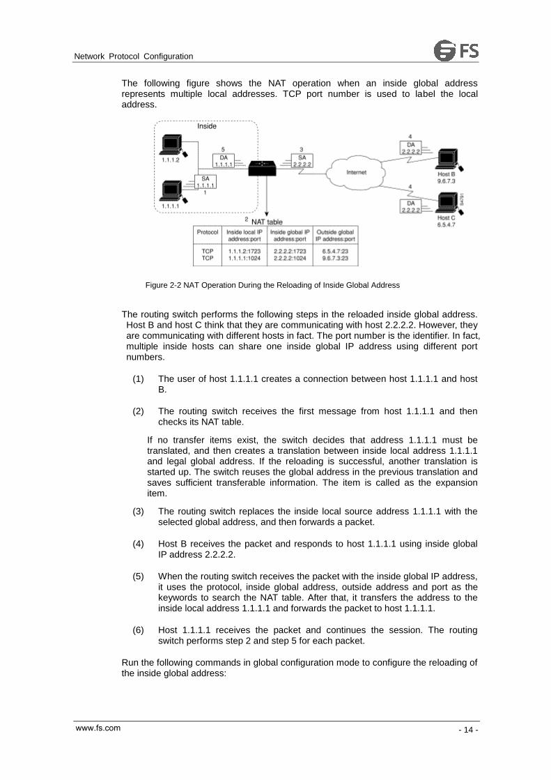
The following figure shows the NAT operation when an inside global address represents multiple local addresses. TCP port number is used to label the local address.
Figure 2-2 NAT Operation During the Reloading of Inside Global Address
The routing switch performs the following steps in the reloaded inside global address. Host B and host C think that they are communicating with host 2.2.2.2. However, they are communicating with different hosts in fact. The port number is the identifier. In fact, multiple inside hosts can share one inside global IP address using different port numbers.
(1) The user of host 1.1.1.1 creates a connection between host 1.1.1.1 and host B.
(2) The routing switch receives the first message from host 1.1.1.1 and then checks its NAT table.
If no transfer items exist, the switch decides that address 1.1.1.1 must be translated, and then creates a translation between inside local address 1.1.1.1 and legal global address. If the reloading is successful, another translation is started up. The switch reuses the global address in the previous translation and saves sufficient transferable information. The item is called as the expansion item.
(3) The routing switch replaces the inside local source address 1.1.1.1 with the selected global address, and then forwards a packet.
(4) Host B receives the packet and responds to host 1.1.1.1 using inside global IP address 2.2.2.2.
(5) When the routing switch receives the packet with the inside global IP address, it uses the protocol, inside global address, outside address and port as the keywords to search the NAT table. After that, it transfers the address to the inside local address 1.1.1.1 and forwards the packet to host 1.1.1.1.
(6) Host 1.1.1.1 receives the packet and continues the session. The routing switch performs step 2 and step 5 for each packet.
Run the following commands in global configuration mode to configure the reloading of the inside global address:
www.fs.com

Network Protocol Configuration
- 15 -
Run… To…
ip nat pool name start-ip end-ip netmask Define a to-be-distributed global address
pool according to requirements.
ip access-list standard access-list-name
permit source [source-mask]
Define a standard access list.
ip nat inside source list access-list-name
pool name overload
Create dynamic inside source address
transfer and decide the access list
previously defined.
interface type number Specify the inside interface.
ip nat inside Label the interface as one to connect the
inside network.
interface type number Specify the outside interface.
ip nat outside Label the interface as one to connect the
outside network.
Note:
Only those transferable addresses can be contained in the access list (remember that an implicit item “deny all” exists at the end of each access list). The random access list may lead to unexpected results.
Refer to section 2.4.2 “Inside Global Address Reloading Example” for details.关
2.3.3 Translating Overlapping Addresses
When an internal local address is the same as the to-be-connected outside address, address overlapping occurs. The following figure shows how NAT translates the overlapping addresses.
Figure 2-3 Network Condition Where NAT Translates Overlapping Addresses
The routing switch performs the following steps when translating the overlapping addresses:
www.fs.com

Network Protocol Configuration
- 16 -
(1) The user of host 1.1.1.1 uses domain name to send instructions for connecting host C. Host 1.1.1.1 requires DNS server to perform a checkup from domain name to address.
(2) The DNS server responds the request and returns the address 1.1.1.1 of host C. The routing switch intercepts the DNS response message and selects an outside local address from the outside local address pool to replace the source address. In this case, the source address 1.1.1.1 is replaced with address 3.3.3.3.
(3) The routing switch creates a mapping table about address transfer, where inside local addresses and inside global addresses map each other, outside global address and outside local address map each other.
(4) Host 1.1.1.1 sends message to host C . The destination IP address is the outside local address 3.3.3.3.
(5) When switch A receives message whose destination address is the outside local address, switch A transfers the local address to the global address.
(6) Host C receives the packet and continues the session.
1. Configuring static transfer
Run the following commands in global configuration mode to configure static source address translation:
Run… To…
ip nat outside source static global-ip
local-ip
Creates static translation between outside
local address and outside global address.
interface type number Specify the inside interface.
ip nat inside Label the interface as one to connect the
inside network.
interface type number Specify the outside interface.
ip nat outside Label the interface as one to connect the
outside network.
2. Configuring dynamic transfer
Run the following commands in global configuration mode to configure dynamic outside source address transfer:
Run… To…
ip nat pool name start-ip end-ip netmask Define a to-be-distributed local address pool
according to requirements.
ip access-list standard access-list-name
permit source [source-mask]
Define a standard access list.
ip nat outside source list access-list-name
pool name
Create dynamic outside source address
transfer and decide the access list
previously defined.
interface type number Specify the inside interface.
www.fs.com

Network Protocol Configuration
- 17 -
ip nat inside Label the interface as one to connect the
inside network.
interface type number Specify the outside interface.
ip nat outside Label the interface as one to connect the
outside network.
Note:
Only those transferable addresses can be contained in the access list (remember that an implicit item “deny all” exists at the end of each access list). The random access list may lead to unexpected results.
For details, refer to section“Overlapping Address Translation Example”.
2.3.4 Providing TCP Load Balance
Another fashion of using NAT is unrelated to the Internet address. Your organization may have multiple hosts to communicate with a frequently used host. In this case, you can use NAT technology to create a virtual host in the inside network, helping the load balance among actual hosts. You need to replace the destination address of the access list with the address in the cycle address pool. The distribution is complete in a cycle when a new connection from the outside to the inside is opened. The non-TCP communication need not be translated (unless other translations are effective). The following figure illustrates the attribute.
Figure 2-4 NAT TCP load balance
When translating the cycle address, the routing switch performs the following steps:
(1) The user of host B (9.6.7.3) sends instructions for connecting the virtual host 1.1.1.127 in the inside network.
(2) The routing switch receives the connection request and creates a new translation item to allocate the next host 1.1.1.1 for the inside local IP address.
www.fs.com

Network Protocol Configuration
- 18 -
(3) The routing switch replaces the destination address with the selected actual address of the host, and forwards the message.
(4) Host 1.1.1.1 receives the message and makes response.
(5) The routing switch receives the message and uses the inside local addresses and their port numbers, the outside address and port number as keywords to check the NAT table. The routing switch then transfers the source address to the address of the virtual host, and forwards the message.
(6) Next connection request invokes the routing switch to distribute address 1.1.1.2 for the inside local address. To configure the destination address transfer, run the following commands in global configuration mode. These commands permit to map one virtual host to multiple real hosts. Each TCP session with the virtual host will be transferred to the sessions with different real hosts.
(7)
Run... To...
ip nat pool name start-ip end-ip netmask Define an address pool containing the
addresses of real hosts.
ip access-list standard access-list-name
permit source [source-mask]
Define an access table permitting addresses
of virtual hosts.
ip nat inside destination list
access-list-name pool name
Create a dynamic inside target transfer
mechanism and confirm the previously
defined access list.
interface type number Specify the inside interface.
ip nat inside Label the interface as one to connect the
inside network.
interface type number Specify the outside interface.
ip nat outside Label the interface as one to connect the
outside interface.
Note:
Only those transferable addresses can be contained in the access list (remember that an implicit item “deny all” exists at the end of each access list). The random access list may lead to unexpected results.
For details, refer to section “TCP Load Configuration Example”.
2.3.5 Changing Translation Timeout Time and Limiting the Number of Connections
After a period of leisure, the dynamic Network Address Translation (NAT) is to time out by default. If the reloading is not configured, the simple translation item is to time out after one hour. You can run the following command to in global configuration mode to change the timeout value.
Run... To...
ip nat translation timeout seconds Change the timeout value of the dynamic NAT
without reloading.
www.fs.com

Network Protocol Configuration
- 19 -
If the reloading is configured, the translation timeout will be better controlled because every translation item contains more contents. To change the timeout value of the expansible item, run one or most of the following commands in global configuration mode.
Run... To...
ip nat translation udp-timeout seconds Change the UDP timeout value (the default
value is five seconds).
ip nat translation dns-timeout seconds Change the DNS timeout value (the default
value is one second).
ip nat translation tcp-timeout seconds Change the TCP timeout value (the default
value is one hour).
ip nat translation icmp-timeout seconds Set the timeout time of the ICMP NAT (the
default time is 60 seconds).
ip nat translation syn-timeout seconds Set the timeout time of the NAT in the TCP
SYN state (the default time is 60 seconds).
ip nat translation finrst-timeout seconds Change the TCP FIN/RST timeout value (the
default value is 60 seconds).
There are three methods to limit the NAT connections. Run the following commands in global configuration mode to realize the three methods.
Run... To...
ip nat translation max-entries numbers Set the maximum number of the translation
items (the default value is 4000).
ip nat translation max-links A.B.C.D
numbers
Limit the maximum number of the NAT
connection items that the designated inside IP
address creates. There is no default value.
ip nat translation max-links all numbers Limit the maximum number of the NAT
connection items that a single IP address
creates. The default value is the same as
max-entries.
2.3.6 Monitoring and Maintaining NAT
The dynamic NAT is to time out by default according to the time regulated by the NAT transfer table. You can run the following commands in management mode to clear up the timeout item before the timeout occurs.
Run... To...
clear ip nat translation * Clear up all transfer items from the NAT
transfer table.
clear ip nat translation inside local-ip
global-ip [outside local-ip global-ip]
Clear up a simple dynamic translation item
containing inside translation, outside
translation or both.
clear ip nat translation outside local-ip
global-ip
Clear up a simple dynamic translation item
containing outside translation.
clear ip nat translation inside local-ip
local-port global-ip global-port [outside local-ip
local-port global-ip global-port]
Clear up expansible dynamic translation
items.
www.fs.com

Network Protocol Configuration
- 20 -
Run one of the following commands in management mode to display the transfer information:
Run... To...
show ip nat translations [verbose] Display active translation.
show ip nat statistics Display translation statistics.
2.4 NAT Configuration Example
2.4.1 Dynamic Inside Source Transfer Example
The following example shows how to transfer all source addresses (192.168.1.0/24) that matches access list a1 to one address in the net-208 pool whose address range is from 171.69.233.208 to 171.69.233.233.
ip nat pool net-208 171.69.233.208 171.69.233.233 255.255.255.240
ip nat inside source list a1 pool net-208
!
interface vlan10
ip address 171.69.232.182 255.255.255.240
ip nat outside
!
interface vlan11
ip address 192.168.1.94 255.255.255.0
ip nat inside
!
ip access-list standard a1
permit 192.168.1.0 255.255.255.0
!
2.4.2 Inside Global Address Reloading Example
An address pool named net-208 is created in the following example. The address pool contains all addresses from 171.69.233.208 to 171.69.233.233. The a1 access list permits all packets from source addresses from 192.168.1.0 to 192.168.1.255. If there is no transfer, packets matching the a1 access list are to be transferred to one address the net-208 address pool. The routing switch authorizes multiple local addresses (from 192.168.1.0 to 192.168.1.255) to use the same global address. The routing switch stores the port numbers to distinguish every connection.
ip nat pool net-208 171.69.233.208 171.69.233.233 255.255.255.240
ip nat inside source list a1 pool net-208 overload
!
interface vlan10
ip address 171.69.232.182 255.255.255.240
ip nat outside
!
interface vlan11
ip address 192.168.1.94 255.255.255.0
www.fs.com

Network Protocol Configuration
- 21 -
ip nat inside
!
ip access-list standard a1
permit 192.168.1.0 255.255.255.0
!
2.4.3 Example to overlapping address transfer
The following example shows that other users in the Internet are legally using the address in the local network. Extra transfer is needed to access the outside network. The net-10 address pool is an outside local IP address pool. The sentence ip nat outside source list 1 pool net-10 transfer the host addresses of the outside
overlapping network to the address in the net-10 address pool.
ip nat pool net-208 171.69.233.208 171.69.233.223 255.2555.255.240
ip nat pool net-10 10.0.1.0 10.0.1.255 255.255.255.0
ip nat inside source list a1 pool net-208
ip nat outside source list a1 pool net-10
!
interface vlan10
ip address 171.69.232.192 255.255.255.240
ip nat outside
!
interface vlan11
ip address 192.168.1.94 255.255.255.0
ip nat inside
!
ip access-list standard a1
permit 192.168.1.0 255.255.255.0
!
2.4.4 TCP Load Distribution Example
The following example shows that the connections between a virtual address and a group of actual hosts are distributed. The address pool defines the addresses of actual hosts. The access list defines the virtual address. The TCP packet that matches the access list and is from serial port 1/0 (outside interface) is to be translated to the address in the pool.
ip nat pool real-hosts 192.168.15.2 192.168.15.15 255.255.255.240
ip nat inside destination list a2 pool real-hosts
!
interface vlan10
ip address 192.168.15.129 255.255.255.240
ip nat outside
!
interface vlan11
ip address 192.168.15.17 255.255.255.240
ip nat inside
www.fs.com

Network Protocol Configuration
- 22 -
!
ip access-list standard a2
permit 192.168.15.1 255.255.255.0
www.fs.com

Network Protocol Configuration
- 23 -
Chapter 3 Configuring DHCP
3.1 Introduction
The Dynamic Host Configuration Protocol (DHCP) provides some parameters of network configuration fro hosts in the Internet. DHCP will be described in RFC 2131. The most important function of DHCP is to distribute IP addresses on the interface. DHCP supports three mechanisms of distributing IP addresses.
Automatic distribution
The DHCP server automatically distributes a permanent IP address to a client.
Dynamic distribution
The DHCP server distributes an IP address for a client to use for a certain periodof time or until the client does not use it.
Manual distribution
The administrator of the DHCP server manually specifies an IP address andthrough the DHCP protocol sends it to the client.
3.1.1 DHCP Applications
DHCP has several kinds of applications. You can use DHCP in the following cases:
You can distribute IP address, network segment and related sources (such asrelevant gateway) to an Ethernet interface by configuring the DHCP client.
When a switch that can access DHCP connects multiple hosts, the switch canobtain an IP address from the DHCP server through the DHCP relay and thendistribute the address to the hosts.
3.1.2 DHCP Advantages
In current software version, the DHCP client or the DHCP client on the Ethernet interface is supported. The function to support the DHCP client has the following advantages:
Reducing the configuration time
Reducing configuration faults
Controlling IP addresses of some device ports through the DHCP server
www.fs.com

Network Protocol Configuration
- 24 -
3.1.3 DHCP Terminology
DHCP is based on the Server/Client model. The DHCP-server and DHCP-client exist in the DHCP running conditions.
DHCP-Server
It is a device to distribute and recycle the DHCP-related sources such as IPaddresses and lease time.
DHCP-Client
It is a device to obtain information from the DHCP server for devices of the localsystem to use, such as IP address information.
As described above, the lease time is a concept appearing in the procedure of DHCP dynamic distribution.
Lease time—an effective period of an IP address since its distribution. When theeffective period is over, the IP address is to be recycled by the DHCP server. Tocontinuously use the IP address, the DHCP client requires re-applying the IPaddress.
3.2 Configuring DHCP Client
3.2.1 DHCP Client Configuration Tasks
Obtaining an IP address
Specifying an address for DHCP server
Configuring DHCP parameters
Monitoring DHCP
3.2.2 DHCP Client Configuration Tasks
1. Obtaining an IP address
Run the following command on the VLAN interface to obtain an IP address through the DHCP protocol for an interface.
Run... To...
ip address dhcp Specify the DHCP protocol to configure the
IP address of the Ethernet interface.
www.fs.com
Network Protocol Configuration
- 25 -
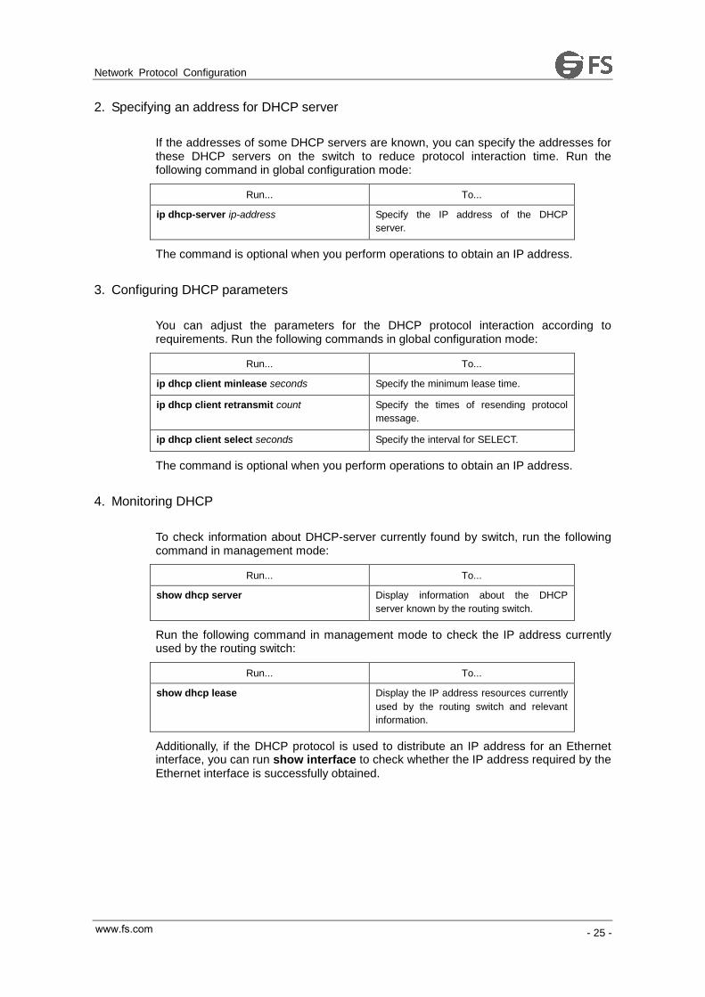
2. Specifying an address for DHCP server
If the addresses of some DHCP servers are known, you can specify the addresses for these DHCP servers on the switch to reduce protocol interaction time. Run the following command in global configuration mode:
Run... To...
ip dhcp-server ip-address Specify the IP address of the DHCP
server.
The command is optional when you perform operations to obtain an IP address.
3. Configuring DHCP parameters
You can adjust the parameters for the DHCP protocol interaction according to requirements. Run the following commands in global configuration mode:
Run... To...
ip dhcp client minlease seconds Specify the minimum lease time.
ip dhcp client retransmit count Specify the times of resending protocol
message.
ip dhcp client select seconds Specify the interval for SELECT.
The command is optional when you perform operations to obtain an IP address.
4. Monitoring DHCP
To check information about DHCP-server currently found by switch, run the following command in management mode:
Run... To...
show dhcp server Display information about the DHCP
server known by the routing switch.
Run the following command in management mode to check the IP address currently used by the routing switch:
Run... To...
show dhcp lease Display the IP address resources currently
used by the routing switch and relevant
information.
Additionally, if the DHCP protocol is used to distribute an IP address for an Ethernet interface, you can run show interface to check whether the IP address required by the
Ethernet interface is successfully obtained.
www.fs.com

Network Protocol Configuration
- 26 -
3.2.3 DHCP Client Configuration Example
1. Obtaining an IP address
The following example shows Ethernet1/1 obtains an IP address through DHCP.
!
interface vlan 11
ip address dhcp
3.3 Configuring DHCP Server
3.3.1 DHCP Server Configuration Tasks
Enabling DHCP server
Disabling DHCP server
Configuring ICMP detection parameter
Configuring database storage parameter
Configuring the address pool of DHCP server
Configuring the parameter for the address pool of DHCP server
Monitoring DHCP server
Clearing information about DHCP server
3.3.2 Configuring DHCP Server
1. Enabling DHCP server
To enable the DHCP server and distribute parameters such as IP address for the DHCP client, run the following command in global configuration mode (the DHCP server also supports the relay operation. For the addresses that the DHCP server cannot distribute, the port where ip helper-address is configured is to forward the
DHCP request):
Run... To...
ip dhcpd enable Enabling DHCP server.
2. Disabling DHCP server
To enable DHCP server and stop distributing parameters such as IP address parameter for the DHCP client, run the following command in global configuration mode:
www.fs.com

Network Protocol Configuration
- 27 -
Run... To...
no ip dhcpd enable Disable DHCP server.
3. Configuring ICMP detection parameter
You can adjust the parameter of the to-be-sent ICMP message when the server performs address detection. Run the following command in global configuration mode to configure the number of to-be-sent ICMP messages:
Run... To...
ip dhcpd ping packets pkgs Specify the times of address detection as
the number of to-be-sent ICMP message.
Run the following command in global configuration mode to configure the timeout time of ICMP message response:
Run... To...
ip dhcpd ping timeout timeout Specify the timeout time of ICMP message
response.
4. Configuring database storage parameter
To configure the interval when the address distribution information is stored in the agent database, run the following command in global configuration mode.
Run... To...
ip dhcpd write-time time Specify the interval at which the address
distribution information is stored in the
agent database.
5. Configuring DHCP server address pool
Run the following command in global configuration mode to add the address pool for the DHCP server:
Run... To...
ip dhcpd pool name Add the address pool of the DHCP server
and enter the configuration mode of the
DHCP address pool.
6. Configuring DHCP server address pool
You can run the following commands in DHCP address pool configuration mode to configure related parameters.
Run the following command to configure the network address of the address pool which is used for automatic distribution.
Run... To...
network ip-addr netsubnet Configure the network address of the
address pool which is used for automatic
www.fs.com

Network Protocol Configuration
- 28 -
distribution.
Run the following command to configure the address range that is used for automatic distribution.
Run... To...
range low-addr high-addr Configure the address range that is used
for automatic distribution.
Run the following command to configure the default route that is distributed to the client:
Run... To...
default-router ip-addr … Configure the default route that is
distributed to the client.
Run the following command to configure the DNS server address that is distributed to the client:
Run... To...
dns-server ip-addr … Configure the DNS server address that is
distributed to the client.
Run the following command to configure domain that is distributed to the client:
Run... To...
domain-name name Configure domain that is distributed to the
client.
Run the following command to configure the lease time of the address that is distributed to the client:
Run... To...
lease {days [hours][minutes] | infinite } Configure the lease time of the address
that is distributed to the client.
Run the following command to configure the netbios server address that is distributed to the client:
Run... To...
netbios-name-server ip-addr… Configure the netbios server address that
is distributed to the client.
You can run the following command to reject to distribute the IP address to the host whose MAC address is hardware-address.
Run… To…
hw-access deny hardware-address Reject to distribute IP addresses to the
host whose MAC address is
hardware-address.
7. Monitoring DHCP server
Run the following command in management mode to check current address distribution information about DHCP server.
www.fs.com

Network Protocol Configuration
- 29 -
Run… To…
show ip dhcpd binding Display current address distribution
information about DHCP server.
Run the following command in management mode to check current message statistics information about DHCP server.
Run… To…
show ip dhcpd statistic Display current message statistics
information about DHCP server.
8. Clearing up information about DHCP server
Run the following command in management mode to delete current address distribution information about DHCP server:
Run... To...
clear ip dhcpd binding {ip-addr|*} Delete the designated address distribution
information.
Run the following command in management mode to delete current message statistics information about DHCP server.
Run... To...
clear ip dhcpd statistic Delete current message statistics
information about DHCP server.
3.3.3 DHCP Server Configuration Example
In the following example, the timeout time of the ICMP detection packet is set to 200ms; Address pool 1 is configured and the DHCP server is enabled.
ip dhcpd ping timeout 2
ip dhcpd pool 1
network 192.168.20.0 255.255.255.0
range 192.168.20.211 192.168.20.215
domain-name my315
default-router 192.168.20.1
dns-server 192.168.1.3 61.2.2.10
netbios-name-server 192.168.20.1
lease 1 12 0
!
ip dhcpd enable
www.fs.com

Network Protocol Configuration
- 30 -
Chapter 4 IP Service Configuration
It is to describe how to configure optional IP service. For the details of the IP service commands, refer to section “IP Service Commands”.
4.1 Configuring IP Service
Optional IP service configuration tasks are listed as follows:
Managing IP connection
Configuring performance parameters
Configuring default gateway
Detecting and maintaining IP network
The above operations are not mandatory. You can perform the operations according to your requirements.
4.1.1 Managing IP Connection
The IP protocol provides a series of services to control and manage IP connections. Most of these services are provided by ICMP. The ICMP message is sent to the host or other routing switches when the routing switch or the access server detects faults in the IP message header. ICMP is mainly defined in RFC 792.
Perform the following different operations according to different IP connection conditions:
1. Sending ICMP unreachable message
If the system receives a message and cannot send it to the destination, such as no routes, the system will send an ICMP-unreachable message to the source host. The function of the system is enabled by default.
If the function is disabled, you can run the following command in interface configuration mode to enable the function.
Run… To…
ip unreachables Enable the function to send an
ICMP-unreachable message.
2. Sending ICMP redirection message
Sometimes the host selects an unfavorable route. After a routing switch on the route receives a message from the host, it is to check the routing table and then forward the message through the message-receiving interface to another routing switch that is in
www.fs.com

Network Protocol Configuration
- 31 -
the same network segment as the host. In this case, the routing switch notifies the source host of directly sending the message with the destination to another routing switch without winding itself. The redirection message requires the source host to discard the original route and take more direct route suggested in the message. Many host’s operating system adds a host route to its routing table. However, the routing switch is more willing to trust information obtained through the routing protocol. Therefore, the routing switch would not add the host route according to the information.
The function is enabled by default. If the hot standby routing switch protocol is configured on the interface, the function is automatically disabled. However, the function will not be automatically enabled even if the hot standby routing switch protocol is cancelled.
To enable the function, run the following command in interface configuration mode:
Run… To…
ip redirects Permit sending the ICMP redirection
messafge.
3. Sending ICMP mask response message
Sometimes the host must know the network mask. To get the information, the host can send the ICMP mask request message. If the routing switch can confirm the mask of the host, it will respond with the ICMP mask response message. By default, the routing switch can send the ICMP mask response message.
To send the ICMP mask request message, run the following command in interface configuration mode:
Run… To…
ip mask-reply Send the ICMP mask response message.
4. Supporting route MTU detection
The system supports the IP route MTU detection mechanism defined by RFC 1191. The IP route MTU detection mechanism enables the host to dynamically find and adjust to the maximum transmission unit (MTU) of different routes. Sometimes the routing switch detects that the received IP message length is larger than the MTU set on the message forwarding interface. The IP message needs to be segmented, but the “unsegmented” bit of the IP message is reset. The message, therefore, cannot be segmented. The message has to be dropped. In this case, the routing switch sends the ICMP message to notify the source host of the reason of failed forwarding, and the MTU on the forwarding interface. The source host then reduces the length of the message sent to the destination to adjust to the minimum MTU of the route.
If a link in the route is disconnected, the message is to take other routes. Its minimum MTU may be different from the original route. The routing switch then notifies the source host of the MTU of the new route. The IP message should be packaged with the minimum MTU of the route as much as possible. In this way, the segmentation is avoided and fewer message is sent, improving the communication efficiency.
Relevant hosts must support the IP route MTU detection. They then can adjust the length of IP message according to the MTU value notified by the routing switch, preventing segmentation during the forwarding process.
www.fs.com

Network Protocol Configuration
- 32 -
5. Setting IP maximum transmission unit
All interfaces have a default IP maximum transmission unit (MTU), that is, the transmissible maximum IP message length. If the IP message length exceeds MTU, the routing switch segments the message.
Changing the MTU value of the interface is to affect the IP MTU value. If IP MTU equals to MTU, IP MTU will automatically adjust itself to be the same as new MTU as MTU changes. The change of IP MTU, however, does not affect MTU. IP MTU cannot bigger than MTU configured on the current interface. Only when all devices connecting the same physical media must have the same MTU protocol can normal communication be created.
To set IP MTU on special interface, run the following command in interface configuration mode:
Run… To…
ip mtu bytes Set IP MTU of the interface.
6. Authorizing IP source route
The routing switch checks the IP header of every message. The routing switch supports the IP header options defined by RFC 791: strict source route, relax source route, record route and time stamp. If the switch detects that an option is incorrectly selected, it will send message about the ICMP parameter problem to the source host and drop the message. If problems occur in the source route, the routing switch will send ICMP unreachable message (source route fails) to the source host.
IP permits the source host to specify the route of the IP network for the message. The specified route is called as the source route. You can specify it by selecting the source route in the IP header option. The routing switch has to forward the IP message according to the option, or drop the message according to security requirements. The routing switch then sends ICMP unreachable message to the source host. The routing switch supports the source route by default.
If the IP source route is disabled, run the following command in global configuration mode to authorize the IP source route:
Run… To…
ip source-route Authorizing IP source route.
7. Allowing IP fast exchange
IP fast exchange uses the route cache to forward the IP message. Before the switch forwards message to a certain destination, its system will check the routing table and then forward the message according to a route. The selected route will be stored in the routing cache of the system software. If latter message will be sent to the same host, the switch will forward latter message according to the route stored in the routing cache. Each time message is forwarded, the value of hit times of the corresponding route item is increasing by 1. When the hit times is equal to the set value, the software routing cache will be stored in the hardware routing cache. The following message to the same host will be forwarded directly by the hardware. If the cache is not used for a period of time, it will be deleted. If the software/hardware cache items reach the upper limitation, new destination hosts are not stored in the cache any more. S3224
www.fs.com

Network Protocol Configuration
- 33 -
series switches can hold 2074 hardware cache items and 1024 software cache items. To allow or forbid fast exchange, run the following command in interface configuration mode:
Run… To…
ip route-cache Allow fast exchange (use the routing cache to
forward the IP message).
no ip route-cache Forbid fast exchange.
To configure the hit times required when the software cache items are stored to the hardware cache, run the following command in global configuration.
Run… To…
ip route-cache hit-numbers
hitnumber
When the hit times of the routing item in the software
cache reaches the value of the parameter hitnumber,
the routing item in the software cache will be stored as a
routing item in the hardware cache.
8. Supporting IP fast exchange on the same interface
You can enable the switch to support IP fast exchange by making the receiving interface the same as the transmitting interface. Generally, it is recommended not to enable the function because it conflicts with the redirection function of the router.
Run the following command in interface configuration mode to allow IP routing cache in the same interface:
Run… To…
ip route-cache same-interface Allow IP message with the same
receiving/transmitting interfaces to be stored in the
routing cache.
4.1.2 Configuring Performance Parameters
1. Setting the wait time for TCP connection
When the routing switch performs TCP connection, it considers that the TCP connection fails if the TCP connection is not created during the wait time. The routing switch then notifies the upper-level program of the failed TCP connection. You can set the wait time for TCP connection. The default value of the system is 75 seconds. The previous configuration has no impact on TCP connections that the switch forwards. It only affects TCP connections that are created by the switch itself.
Run the following command in global configuration mode to set the wait time for TCP connections:
Run… To…
ip tcp synwait-time seconds Set the wait time for TCP connection.
www.fs.com

Network Protocol Configuration
- 34 -
2. Setting the size of TCP windows
The default size of TCP windows is 2000 byte. Run the following command in global configuration mode to change the default window size:
Run… To…
ip tcp window-size bytes Set the size of TCP windows.
4.1.3 Detecting and Maintaining IP Network
1. Clearing cache, list and database
You can clear all content in a cache, list or database. Incorrect data in a cache, list or database need be cleared.
Run the following command to clear incorrect data:
Run… To…
clear tcp statistics Clear TCP statistics data.
2. Clearing TCP connection
To disconnect a TCP connection, run the following command:
Run… To…
clear tcp {local host-name port remote
host-name port | tcb address}
Clear the designated TCP connection.
TCB refers to TCP control block.
3. Displaying statistics data about system and network
The system can display the content in the cache, list and database. These statistics data can help you know the usage of systematic sources and solve network problems.
Run the following commands in management mode. For details, refer to “IP Service Command”.
Run… To…
show ip access-lists name Display the content of one or all access lists.
show ip cache [prefix mask] [type number] Display the routing cache that is used for fast
IP message exchange.
show ip sockets Display all socket information about the routing
switch.
show ip traffic Display statistics data about IP protocol.
show tcp Display information about all TCP connection
states.
show tcp brief Briefly display information about TCP
www.fs.com
www.fs.com

Network Protocol Configuration
- 35 -
connection states.
show tcp statistics Display TCP statistics data.
show tcp tcb Display information about the designated TCP
connection state.
4. Displaying debugging information
When problem occurs on the network, you can run debug to display the debugging information.
Run the following command in management mode. For details, refer to “IP Service Command”.
Run… To…
debug arp Display the interaction information about ARP.
debug ip icmp Display the interaction information about ICMP.
debug ip raw Display the information about received/transmitted IP
message.
debug ip packet Display the interaction information about IP.
debug ip tcp Display the interaction information about TCP.
debug ip udp Display the interaction information about UDP.
4.2 Configuring Access List
4.2.1 Filtering IP Message
Filtering message helps control the movement of packet in the network. The control can limit network transmission and network usage through a certain user or device. To make packets valid or invalid through the crossly designated interface, our routing switch provides the access list. The access list can be used in the following modes:
Controlling packet transmission on the interface
Controlling virtual terminal line access
Limiting route update content
The section describes how to create IP access lists and how to use them.
The IP access list is an orderly set of the permit/forbid conditions for applying IP
addresses. The ROS software of our switch tests the address one by one in the access list according to regulations. The first match determines whether the ROS accepts or declines the address. After the first match, the ROS software terminates the match regulations. The order of the conditions is, therefore, important. If no regulations match, the address is declined.
Use the access list by following the following steps:
www.fs.com

Network Protocol Configuration
- 36 -
(1) Create the access list by designating the access list name and conditions.
(2) Apply the access list to the interface.
4.2.2 Creating Standard and Extensible IP Access List
Use a character string to create an IP access list.
Note:
The standard access list and the extensible access list cannot have the same name.
Run the following command in global configuration mode to create a standard access list:
Run… To…
ip access-list standard name Use a name to define a standard access list.
deny {source [source-mask] | any}[log] or
permit {source [source-mask] | any}[log]
Designate one or multiple permit/deny
conditions in standard access list
configuration mode. The previous setting
decides whether the packet is approved or
disapproved.
Exit Log out from the access list configuration
mode.
Run the following command in global configuration mode to create an extensible access list.
Run… To…
ip access-list extended name Use a name to define an extensible IP
access list.
{deny | permit} protocol source
source-mask destination destination-mask
[precedence precedence] [tos tos]
[established] [log]{deny | permit} protocol
any any
Designate one or multiple permit/deny
conditions in extensible access list
configuration mode. The previous setting
decides whether the packet is approved or
disapproved.
precedence means the priority of the IP
packet; TOS means Type of Service.
Exit Log out from the access list configuration
mode.
After the access list is originally created, any part that is added later can be put at the end of the list. That is to say, you cannot add the command line to the designated access list. However, you can run no permit and no deny to delete items from the
access list.
Note:
When you create the access list, the end of the access list includes the implicit deny sentence by default. If the mask is omitted in the relative IP host address access list, 255.255.255.255 is supposed to be the mask.
www.fs.com

Network Protocol Configuration
- 37 -
After the access list is created, the access list must be applied on the route or interface. For details, refer to section 4.2.3 “Applying the Access List to the Interface”.
4.2.3 Applying the Access List to the Interface
After the access list is created, you can apply it to one or multiple interfaces including the in interfaces and out interfaces.
Run the following command in interface configuration mode.
Run… To…
ip access-group name {in | out} Apply the access list to the interface.
The access list can be used on the in interfaces and the out interfaces. For the standard access list of the in interface, the soured address of the packet is to be checked according to the access list after the packet is received. For the extensible access list, the routing switch also checks the destination. If the access list permits the address, the software goes on processing the packet. If the access list does not permit the address, the software drops the packet and returns an ICMP unreachable message.
For the standard access list of the out interfaces, after a packet is received or routed to the control interface, the software checks the source address of the packet according to the access list. For the extensible access list, the routing switch also checks the access list of the receiving side. If the access list permits the address, the software will send the packet. If the access list does not permit the address, the software drops the packet and returns an ICMP unreachable message.
If the designated access list does not exist, all packets allows to pass.
4.2.4 Extensible Access List Example
In the following example, the first line allows any new TCP to connect the destination port after port 1023. The second line allows any new TCP to connect the SMTP port of host 130.2.1.2.
ip access-list extended aaa
permit tcp any 130.2.0.0 255.255.0.0 gt 1023
permit tcp any 130.2.1.2 255.255.255.255 eq 25
interface vlan 10
ip access-group aaa in
Another example to apply the extensible access list is given. Suppose a network connects the Internet, you expect any host in the Ethernet can create TCP connection with the host in the Internet. However, you expect the host in the Internet cannot create TCP connection with the host in the Ethernet unless it connects the SMTP port of the mail host.
During the connection period, the same two port numbers are used. The mail packet from the Internet has a destination port, that is, port 25. The outgoing packet has a contrary port number. In fact, the security system behind the routing switch always receives mails from port 25. That is the exact reason why the incoming service and the outgoing service can be uniquely controlled. The access list can be configured as the outgoing service or the incoming service.
www.fs.com

Network Protocol Configuration
- 38 -
In the following case, the Ethernet is a B-type network with the address 130.20.0.0. The address of the mail host is 130.20.1.2. The keyword established is only used for the TCP protocol, meaning a connection is created. If TCP data has the ACK or RST digit to be set, the match occurs, meaning that the packet belongs to an existing connection.
ip access-list aaa
permit tcp any 130.20.0.0 255.255.0.0 established
permit tcp any 130.20.1.2 255.255.255.255 eq 25
interface vlan 10
ip access-group aaa in
4.3 Configuring IP Access List Based on Physical Port
4.3.1 Filtering IP Message
4.3.2 Filtering IP Message
Filtering message helps control the movement of packet in the network. The control can limit network transmission and network usage through a certain user or device. To make packets valid or invalid through the crossly designated interface, our routing switch provides the access list. The access list can be used in the following modes:
Controlling packet transmission on the interface
Controlling virtual terminal line access
Limiting route update content
The section describes how to create IP access lists and how to use them.
The IP access list is an orderly set of the permit/forbid conditions for applying IP
addresses. The ROS software of our switch tests the address one by one in the access list according to regulations. The first match determines whether the ROS accepts or declines the address. After the first match, the ROS software terminates the match regulations. The order of the conditions is, therefore, important. If no regulations match, the address is declined.
Use the access list by following the following steps:
(3) Create the access list by designating the access list name and conditions.
(4) Apply the access list to the interface.
4.3.3 Creating Standard and Extensible IP Access List
Use a character string to create an IP access list.
Note:
www.fs.com

Network Protocol Configuration
- 39 -
The standard access list and the extensible access list cannot have the same name.
Run the following command in global configuration mode to create a standard access list:
Run… To…
ip access-list standard name Use a name to define a standard access list.
deny {source [source-mask] | any}[log] or
permit {source [source-mask] | any}[log]
Designate one or multiple permit/deny
conditions in standard access list
configuration mode. The previous setting
decides whether the packet is approved or
disapproved.
Exit Log out from the access list configuration
mode.
Run the following command in global configuration mode to create an extensible access list.
Run… To…
ip access-list extended name Use a name to define an extensible IP
access list.
{deny | permit} protocol source
source-mask destination destination-mask
[precedence precedence] [tos tos]
[established] [log]{deny | permit} protocol
any any
Designate one or multiple permit/deny
conditions in extensible access list
configuration mode. The previous setting
decides whether the packet is approved or
disapproved.
precedence means the priority of the IP
packet; TOS means Type of Service.
Exit Log out from the access list configuration
mode.
After the access list is originally created, any part that is added later can be put at the end of the list. That is to say, you cannot add the command line to the designated access list. However, you can run no permit and no deny to delete items from the
access list.
Note:
When you create the access list, the end of the access list includes the implicit deny
sentence by default. If the mask is omitted in the relative IP host address access list, 255.255.255.255 is supposed to be the mask.
After the access list is created, the access list must be applied on the route or interface. For details, refer to section 4.2.3 “Applying the Access List to the Interface”.
4.3.4 Applying the Access List to the Interface
After the access list is created, you can apply it to one or multiple interfaces including the in interfaces and out interfaces.
Run the following command in interface configuration mode.
Run… To…
www.fs.com

Network Protocol Configuration
- 40 -
ip access-group name {in | out} Apply the access list to the interface.
The access list can be used on the in interfaces and the out interfaces. For the standard access list of the in interface, the soured address of the packet is to be checked according to the access list after the packet is received. For the extensible access list, the routing switch also checks the destination. If the access list permits the address, the software goes on processing the packet. If the access list does not permit the address, the software drops the packet and returns an ICMP unreachable message.
For the standard access list of the out interfaces, after a packet is received or routed to the control interface, the software checks the source address of the packet according to the access list. For the extensible access list, the routing switch also checks the access list of the receiving side. If the access list permits the address, the software will send the packet. If the access list does not permit the address, the software drops the packet and returns an ICMP unreachable message.
If the designated access list does not exist, all packets allows to pass.
4.3.5 Extensible Access List Example
1. Port-based IP access list supporting TCP/UDP port filtration
{deny | permit} {tcp | udp}
source source-mask [ { [src_portrange begin-port end-port] | [ {gt | lt } port ] }]
destination destination-mask [ { [dst_portrange begin-port end-port] | [ {gt | lt } port ] }]
[precedence precedence] [tos tos]
If you configure the access list by defining the port range, pay attention to the following:
If you use the method of designating the port range to configure the access list atthe source side and the destination side, some configuration may fail because ofmassive resource consumption. In this case, you need to use the fashion ofdesignating the port range at one side, and use the fashion of designating the portat another side.
When the port range filtration is performed, too many resources will be occupied.If the port range filtration is used too much, the access list cannot support otherprograms as well as before.
2. Port-based IP access list supporting TCP/UDP designated port filtration
In the following example, the first line allows any new TCP to connect the SMTP port of host 130.2.1.2.
ip access-list extended aaa
permit tcp any 130.2.1.2 255.255.255.255 eq 25
interface f0/10
ip access-group aaa
www.fs.com