The Network Model Management System By Joel Koepke ERCOT, Network Model Engineer
A P P E N D I X DNetwork Model
In the relational model, the data and the relationships among data are representedby a collection of tables. The network model differs from the relational model inthat data are represented by collections of records, and relationships among dataare represented by links.
In this chapter we illustrate our concepts using a bank enterprise with theschema shown in Figure 2.15.
D.1 Basic Concepts
A network database consists of a collection of records connected to one anotherthrough links. A record is in many respects similar to an entity in the E-R model.Each record is a collection of fields (attributes), each of which contains only onedata value. A link is an association between precisely two records. Thus, a linkcan be viewed as a restricted (binary) form of relationship in the sense of the E-Rmodel.
As an illustration, consider a database representing a customer-account rela-tionship in a banking system. There are two record types, customer and account. Aswe saw earlier, we can define the customer record type, using Pascal-like notation:
type customer = recordcustomer name: string;customer street: string;customer city: string;
end
The account record type can be defined as
type account = recordaccount number: string;balance: integer;
end
The sample database in Figure D.1 shows that Hayes has account A-102, Johnsonhas accounts A-101 and A-201, and Turner has account A-305.
1

2 Appendix D Network Model
Figure D.1 Sample database.
D.2 Data-Structure Diagrams
A data-structure diagram is a schema representing the design of a network database.Such a diagram consists of two basic components:
1. Boxes, which correspond to record types
2. Lines, which correspond to links
A data-structure diagram serves the same purpose as an E-R diagram; namely, itspecifies the overall logical structure of the database. So that you will understandhow such diagrams are structured, we shall show how to transform E-R diagramsinto their corresponding data-structure diagrams.
D.2.1 Binary Relationship
Consider the E-R diagram of Figure D.2a, consisting of two entity sets, customerand account, related through a binary, many-to-many relationship depositor, withno descriptive attributes. This diagram specifies that a customer may have sev-eral accounts, and that an account may belong to several different customers.The corresponding data-structure diagram appears in Figure D.2b. The recordtype customer corresponds to the entity set customer. It includes three fields—
Figure D.2 E-R diagram and its corresponding data-structure diagram.

D.2 Data-Structure Diagrams 3
Figure D.3 Two data-structure diagrams.
customer-name, customer street, and customer city—as defined in Section D.1. Simi-larly, account is the record type corresponding to the entity set account. It includesthe two fields account number and balance. Finally, the relationship depositor hasbeen replaced with the link depositor.
The relationship depositor is many to many. If the relationship depositor wereone to many from customer to account, then the link depositor would have an arrowpointing to customer record type (Figure D.3a). Similarly, if the relationship deposi-tor were one to one, then the link depositor would have two arrows: one pointing toaccount record type and one pointing to customer record type (Figure D.3b). Since,in the E-R diagram of Figure D.2a, the depositor relationship is many to many, wedraw no arrows on the link depositor in Figure D.2b.
A database corresponding to the described schema may thus contain a num-ber of customer records linked to a number of account records. A sample databasecorresponding to the data-structure diagram of Figure D.2 appears in Figure D.4.Since the relationship is many to many, we show that Johnson has accounts A-101and A-201 and that account A-201 is owned by both Johnson and Smith. A sampledatabase corresponding to the data-structure diagram of Figure D.3a is depictedin Figure D.1. Since the relationship is one to many from customer to account, acustomer may have more than one account, as Johnson does—she owns bothA-101 and A-201. An account, however, cannot belong to more than one customer,and the database observes this restriction. Finally, a sample database correspond-ing to the data-structure diagram of Figure D.3b is shown in Figure D.5. Since therelationship is one to one, an account can be owned by precisely one customer,and a customer can have only one account; the sample database follows thoserules.
Figure D.4 Sample database corresponding to diagram of Figure D.2b.

4 Appendix D Network Model
Figure D.5 Sample database corresponding to diagram of Figure D.3b.
If a relationship includes descriptive attributes, the transformation from anE-R diagram to a data-structure diagram is more complicated. A link cannotcontain any data value, so a new record type needs to be created and links needto be established.
Consider the E-R diagram of Figure D.2a. Suppose that we add the attributeaccess date to the relationship depositor, to denote the most recent time that acustomer accessed the account. This newly derived E-R diagram appears in Fig-ure D.6a. To transform this diagram to a data-structure diagram, we must
1. Replace entities customer and account with record types customer and account,respectively.
2. Create a new record type access date with a single field to represent the date.
3. Create the following many-to-one links:
Figure D.6 E-R diagram and its corresponding network diagram.
D.2 Data-Structure Diagrams 5
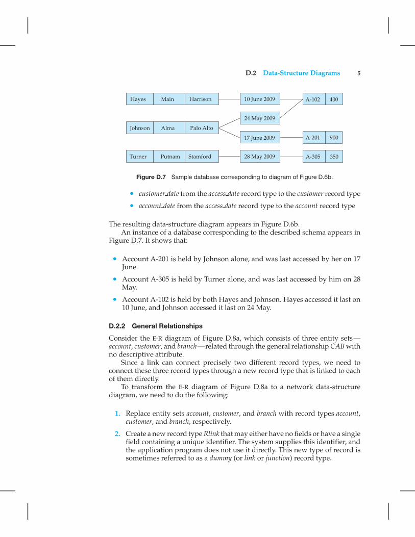
Figure D.7 Sample database corresponding to diagram of Figure D.6b.
• customer date from the access date record type to the customer record type
• account date from the access date record type to the account record type
The resulting data-structure diagram appears in Figure D.6b.An instance of a database corresponding to the described schema appears in
Figure D.7. It shows that:
• Account A-201 is held by Johnson alone, and was last accessed by her on 17June.
• Account A-305 is held by Turner alone, and was last accessed by him on 28May.
• Account A-102 is held by both Hayes and Johnson. Hayes accessed it last on10 June, and Johnson accessed it last on 24 May.
D.2.2 General Relationships
Consider the E-R diagram of Figure D.8a, which consists of three entity sets—account, customer, and branch—related through the general relationship CAB withno descriptive attribute.
Since a link can connect precisely two different record types, we need toconnect these three record types through a new record type that is linked to eachof them directly.
To transform the E-R diagram of Figure D.8a to a network data-structurediagram, we need to do the following:
1. Replace entity sets account, customer, and branch with record types account,customer, and branch, respectively.
2. Create a new record type Rlink that may either have no fields or have a singlefield containing a unique identifier. The system supplies this identifier, andthe application program does not use it directly. This new type of record issometimes referred to as a dummy (or link or junction) record type.

6 Appendix D Network Model
Figure D.8 E-R diagram and its corresponding data-structure diagram.
3. Create the following many-to-one links:
• CustRlnk from Rlink record type to customer record type
• AcctRlnk from Rlink record type to account record type
• BrncRlnk from Rlink record type to branch record type
The resulting data-structure diagram appears in Figure D.8b.A sample database corresponding to the described schema appears in Fig-
ure D.9. It shows that Hayes has account A-102 in the Perryridge branch, Johnsonhas accounts A-101 and A-201 in the Downtown and Perryridge branches, re-spectively, and Turner has account A-305 in the Round Hill branch.
We can extend this technique in a straightforward manner to deal with rela-tionships that span more than three entity sets. We create a many-to-one link fromthe Rlink record to the record types corresponding to each entity set involved inthe relationship. We can also extend the technique to deal with a general rela-tionship that has descriptive attributes. We need to add one field to the dummyrecord type for each descriptive attribute.

D.3 The DBTG CODASYL Model 7
Figure D.9 Sample database corresponding to diagram of Figure D.8b.
D.3 The DBTG CODASYL Model
The first database-standard specification, called the CODASYL DBTG 1971 report,was written in the late 1960s by the Database Task Group. Since then, a numberof changes have been proposed many of which are reflected in our discussionconcerning the DBTG model.
D.3.1 Link Restriction
In the DBTG model, only many-to-one links can be used. Many-to-many links aredisallowed to simplify the implementation. We represent one-to-one links using amany-to-one link. These restrictions imply that the various algorithms of SectionD.2 for transforming an E-R diagram to a data-structure diagram must be revised.
Consider a binary relationship that is either one to many or one to one. Inthis case, the transformation algorithm defined in Section D.2.1 can be applieddirectly. Thus, for our customer-account database, if the depositor relationship isone to many with no descriptive attributes, then the appropriate data-structurediagram is as shown in Figure D.10a. If the relationship has a descriptive attribute(for example, access-date), then the appropriate data-structure diagram is as shownin Figure D.10b.
If the depositor relationship, however, is many to many, then our transforma-tion algorithm must be refined; if the relationship has no descriptive attributes(Figure D.11a), then this algorithm must be employed:
1. Replace the entity sets customer and account with record types customer andaccount, respectively.
2. Create a new dummy record type, Rlink, that may either have no fields orhave a single field containing an externally defined unique identifier.
3. Create the following two many-to-one links:

8 Appendix D Network Model
Figure D.10 Two data-structure diagrams.
• CustRlnk from Rlink record type to customer record type
• AcctRlnk from Rlink record type to account record type
The corresponding data-structure diagram is as shown in Figure D.11b. Aninstance of a database corresponding to the described schema appears in Fig-ure D.12. We encourage you to compare this sample database with the one de-scribed in Figure D.4.
If the relationship depositor is many to many with a descriptive attribute(for example, access date), then the transformation algorithm is similar to the onedescribed. The only difference is that the new record type Rlink now contains thefield access date.
Figure D.11 E-R diagram and its corresponding data-structure diagram.

D.3 The DBTG CODASYL Model 9
Figure D.12 Sample database corresponding to the diagram of Figure D.11.
In the case of general (that is, nonbinary) relationships, the transformationalgorithm is the same as the one described in Section D.2.2. Thus, the E-R diagramof Figure D.8a is transformed into the data-structure diagram of Figure D.8b.
D.3.2 DBTG Sets
Given that only many-to-one links can be used in the DBTG model, a data-structurediagram consisting of two record types that are linked together has the generalform of Figure D.13. This structure is referred to in the DBTG model as a DBTGset. The name of the set is usually chosen to be the same as the name of the linkconnecting the two record types.
In each such DBTG set, the record type A is designated as the owner (or parent)of the set, and the record type B is designated as the member (or child) of the set.Each DBTG set can have any number of set occurrences—that is, actual instancesof linked records. For example, in Figure D.14, we have three set occurrencescorresponding to the DBTG set of Figure D.13.
Since many-to-many links are disallowed, each set occurrence has preciselyone owner, and has zero or more member records. In addition, no member recordof a set can participate in more than one occurrence of the set at any point. A mem-ber record, however, can participate simultaneously in several set occurrences ofdifferent DBTG sets.
As an illustration, consider the data-structure diagram of Figure D.15. Thereare two DBTG sets:
Figure D.13 DBTG set.

10 Appendix D Network Model
Figure D.14 Three set occurrences.
1. depositor, which has customer as the owner of the DBTG set, and account asthe member of the DBTG set
2. account branch, which has branch as the owner of the DBTG set, and accountas the member of the DBTG set
The set depositor can be defined as follows:
set name is depositorowner is customermember is account
The set account branch can be defined similarly:
set name is account branchowner is branchmember is account
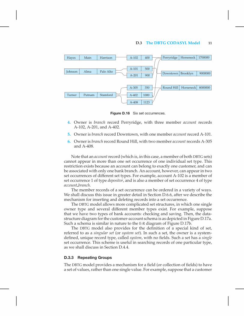
An instance of the database appears in Figure D.16. There are six set occur-rences listed next: three of set depositor (sets 1, 2, and 3), and three of set accountbranch (sets 4, 5, and 6).
1. Owner is customer record Hayes, with a single member account record A-102.
2. Owner is customer record Johnson, with two member account records A-101and A-201.
3. Owner is customer record Turner, with three member account records A-305,A-402, and A-408.
Figure D.15 Data-structure diagram.
D.3 The DBTG CODASYL Model 11
Figure D.16 Six set occurrences.
4. Owner is branch record Perryridge, with three member account recordsA-102, A-201, and A-402.
5. Owner is branch record Downtown, with one member account record A-101.
6. Owner is branch record Round Hill, with two member account records A-305and A-408.
Note that an account record (which is, in this case, a member of both DBTG sets)cannot appear in more than one set occurrence of one individual set type. Thisrestriction exists because an account can belong to exactly one customer, and canbe associated with only one bank branch. An account, however, can appear in twoset occurrences of different set types. For example, account A-102 is a member ofset occurrence 1 of type depositor, and is also a member of set occurrence 4 of typeaccount branch.
The member records of a set occurrence can be ordered in a variety of ways.We shall discuss this issue in greater detail in Section D.6.6, after we describe themechanism for inserting and deleting records into a set occurrence.
The DBTG model allows more complicated set structures, in which one singleowner type and several different member types exist. For example, supposethat we have two types of bank accounts: checking and saving. Then, the data-structure diagram for the customer-account schema is as depicted in Figure D.17a.Such a schema is similar in nature to the E-R diagram of Figure D.17b.
The DBTG model also provides for the definition of a special kind of set,referred to as a singular set (or system set). In such a set, the owner is a system-defined, unique record type, called system, with no fields. Such a set has a singleset occurrence. This scheme is useful in searching records of one particular type,as we shall discuss in Section D.4.4.
D.3.3 Repeating Groups
The DBTG model provides a mechanism for a field (or collection of fields) to havea set of values, rather than one single value. For example, suppose that a customer

12 Appendix D Network Model
Figure D.17 Data-structure and E-R diagram.
has several addresses. In this case, the customer record type will have the (street,city) pair of fields defined as a repeating group. Thus, the customer record forTurner may be as in Figure D.18.
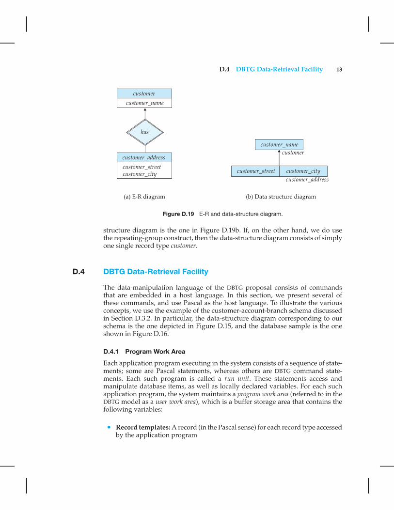
The repeating-groups construct provides another way to represent the notionof weak entities in the E-R model. As an illustration, let us partition the entity setcustomer into two sets:
1. customer, with descriptive attribute customer name
2. customer address, with descriptive attributes customer street and customer city
The customer address entity set is a weak entity set, since it depends on the strongentity set customer.
The E-R diagram describing this schema appears in Figure D.19a. If we do notuse the repeating-group construct in the schema, then the corresponding data-
Figure D.18 A customer record.
D.4 DBTG Data-Retrieval Facility 13
Figure D.19 E-R and data-structure diagram.
structure diagram is the one in Figure D.19b. If, on the other hand, we do usethe repeating-group construct, then the data-structure diagram consists of simplyone single record type customer.
D.4 DBTG Data-Retrieval Facility
The data-manipulation language of the DBTG proposal consists of commandsthat are embedded in a host language. In this section, we present several ofthese commands, and use Pascal as the host language. To illustrate the variousconcepts, we use the example of the customer-account-branch schema discussedin Section D.3.2. In particular, the data-structure diagram corresponding to ourschema is the one depicted in Figure D.15, and the database sample is the oneshown in Figure D.16.
D.4.1 Program Work Area
Each application program executing in the system consists of a sequence of state-ments; some are Pascal statements, whereas others are DBTG command state-ments. Each such program is called a run unit. These statements access andmanipulate database items, as well as locally declared variables. For each suchapplication program, the system maintains a program work area (referred to in theDBTG model as a user work area), which is a buffer storage area that contains thefollowing variables:
• Record templates: A record (in the Pascal sense) for each record type accessedby the application program

14 Appendix D Network Model
• Currency pointers: A set of pointers to various database records most recentlyaccessed by the application program; currency pointers are of the followingtypes:
◦ Current of record type: One currency pointer for each record type Treferenced by the application program; each pointer contains the address(location on disk) of the most recently accessed record of type T
◦ Current of set type: One currency pointer for each set type S referencedby the application program; each pointer contains the address of the mostrecently accessed record of that set type; note that this pointer may pointto a record of either the owner or member type, depending on whether anowner or a member was most recently accessed
◦ Current of run unit: One single currency pointer, containing the address ofthe record (regardless of type) most recently accessed by the applicationprogram
• Status flags: A set of variables used by the system to communicate to theapplication program the outcome of the last operation applied to the database;the most frequently used one is DB-status, set to 0 if the most recent operationsucceeded and otherwise set to an error code.
The additional status variables (DB-set-name, DB-record-name, and DB-data-name) are set when the final operation fails, to help identify the sourceof the difficulty.
We emphasize that a particular program work area is associated with preciselyone application program.
For our customer-account-branch database example, a particular programwork area contains the following:
• Templates: three record types:
◦ customer record
◦ account record
◦ branch record
• Currency pointers: six pointers:
◦ Three currency pointers for record types: one to the most recently accessedcustomer record, one to the most recently accessed account record, and oneto the most recently accessed branch record
◦ Two currency pointers for set types: one to the most recently accessedrecord in an occurrence of the set depositor, and one to the most recentlyaccessed record in an occurrence of the set account branch
◦ One current of run-unit pointer
• Status flags: the four status variables that we defined previously.

D.4 DBTG Data-Retrieval Facility 15
Figure D.20 Program work area.
D.4.2 The Find and Get Commands
The two most frequently used DBTG commands are
• find, which locates a record in the database and sets the appropriate currencypointers
• get, which copies the record to which the current of run unit points from thedatabase to the appropriate program work area template
Let us illustrate the general effect that the find and get statements have on theprogram work area. Consider the sample database of Figure D.16. Suppose thatthe current state of the program work area of a particular application program isas shown in Figure D.20. Further suppose that a find command is issued to locatethe customer record belonging to Johnson. This command causes the followingchanges to occur in the state of the program work area:
• The current of record type customer now points to the record of Johnson.
• The current of set type depositor now points to the record of Johnson.
• The current of run unit now points to customer record Johnson.
16 Appendix D Network Model
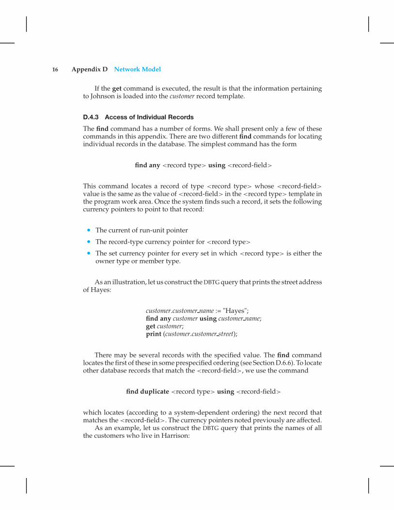
If the get command is executed, the result is that the information pertainingto Johnson is loaded into the customer record template.
D.4.3 Access of Individual Records
The find command has a number of forms. We shall present only a few of thesecommands in this appendix. There are two different find commands for locatingindividual records in the database. The simplest command has the form
find any <record type> using <record-field>
This command locates a record of type <record type> whose <record-field>
value is the same as the value of <record-field> in the <record type> template inthe program work area. Once the system finds such a record, it sets the followingcurrency pointers to point to that record:
• The current of run-unit pointer
• The record-type currency pointer for <record type>
• The set currency pointer for every set in which <record type> is either theowner type or member type.
As an illustration, let us construct the DBTG query that prints the street addressof Hayes:
customer.customer name := "Hayes";find any customer using customer name;get customer;print (customer.customer street);
There may be several records with the specified value. The find commandlocates the first of these in some prespecified ordering (see Section D.6.6). To locateother database records that match the <record-field>, we use the command
find duplicate <record type> using <record-field>
which locates (according to a system-dependent ordering) the next record thatmatches the <record-field>. The currency pointers noted previously are affected.
As an example, let us construct the DBTG query that prints the names of allthe customers who live in Harrison:

D.4 DBTG Data-Retrieval Facility 17
customer.customer city := "Harrison";find any customer using customer city;while DB-status = 0 do
beginget customer;print (customer.customer name);find duplicate customer using customer city;
end;
We have enclosed part of the query in a while loop, because we do not know inadvance how many such customers exist. We exit from the loop when DB-status�= 0. This action indicates that the most recent find duplicate operation failed,implying that we have exhausted all customers residing in Harrison.
D.4.4 Access of Records within a Set
The previous find commands located any database record of type <record type>.In this subsection, we concentrate on find commands that locate records in aparticular DBTG set. The set in question is the one that is pointed to by the <set-type> currency pointer. There are three different types of commands. The basicfind command is
find first <record type> within <set-type>
which locates the first member record of type <record type> belonging to thecurrent occurrence of <set-type>. The various ways in which a set can be orderedare discussed in Section D.6.6.
To step through the other members of type <record type> belonging to theset occurrence, we repeatedly execute the following command:
find next <record type> within <set-type>
The find first and find next commands need to specify the record type since aDBTG set can have members of different record types.
As an illustration of how these commands execute, let us construct the DBTGquery that prints the total balance of all accounts belonging to Hayes.

18 Appendix D Network Model
sum := 0;customer.customer name := "Hayes";find any customer using customer name;find first account within depositor;while DB-status = 0 do
beginget account;sum := sum + account.balance;find next account within depositor;
endprint (sum);
Note that we exit from the while loop and print out the value of sum only whenthe DB-status is set to a value not equal to zero. Such a nonzero value results afterthe find next operation fails, indicating that we have exhausted all the membersof a set occurrence of type depositor, whose owner is the record of customer Hayes.
The previous find commands locate member records within a particular DBTGset occurrence. There are many circumstances, however, under which it may benecessary to locate the owner of a particular DBTG set occurrence. We can do sothrough the following command:
find owner within <set-type>
The set in question is <set-type>. Note that, for each set occurrence, there existsprecisely one single owner.
As an illustration, consider the DBTG query that prints all the customers ofthe Perryridge branch:
branch.branch name := "Perryridge";find any branch using branch name;find first account within account branch;while DB-status = 0 do
beginfind owner within depositor;get customer;print (customer.customer name);find next account within account branch;
end
Note that, if a customer has several accounts in the Perryridge branch, then hisname will be printed several times.
As a final example, consider the DBTG query that prints the names of all thecustomers of the bank. Such a query cannot be formed easily with the mechanismthat we have described thus far, since no one single set has all the customer records

D.4 DBTG Data-Retrieval Facility 19
as its members. The remedy is to define a singular set (Section D.3.2) consistingof members of type customer. This set is defined as follows:
set name is AllCustowner is systemmember is customer
Once such a set has been defined, we can form our query as follows:
find first customer within AllCust;while DB-status = 0 do
beginget customer;print (customer.customer name);find next customer within AllCust;
end
D.4.5 Predicates
The find statements that we have described allow the value of a field in one of therecord templates to be matched with the corresponding field in the appropriatedatabase records. Although, with this technique, we can formulate a variety ofDBTG queries in a convenient and concise way, there are many queries in whicha field value must be matched with a specified range of values, rather than toonly one. To accomplish this match, we need to get the appropriate records intomemory, to examine each one separately for a match, and thus to determinewhether each is the target of our find statement.
As an illustration, consider the DBTG query to print the total number ofaccounts in the Perryridge branch with a balance greater than $10,000:
count := 0;branch.branch name := "Perryridge";find any branch using branch name;find first account within account branch;while DB-status = 0 do
beginget account;if account.balance > 10000 then count := count + 1;find next account within account branch;
endprint (count);

20 Appendix D Network Model
D.5 DBTG Update Facility
In Section D.4, we described the various DBTG commands for querying thedatabase. In this section, we describe the mechanisms available for updating in-formation in the database. They include the creation of new records and deletionof old records, as well as the modification of the content of existing records.
D.5.1 Creation of New Records
To create a new record of type <record type>, we insert the appropriate valuesin the corresponding <record type> template. We then add this new record tothe database by executing
store <record type>
Note that this technique allows us to create and add new records only one at atime.
As an illustration, consider the DBTG program for adding a new customer,Jackson, to the database:
customer.customer name := "Jackson";customer.customer street := "Old Road";customer.customer city := "Richardson";store customer;
Note that, if a new record is created that must belong to a particular DBTG setoccurrence (for example, a new account), then, in addition to the store operation,we need a mechanism for inserting records into set occurrences. This mechanismis described in Section D.6.
D.5.2 Modification of an Existing Record
To modify an existing record of type <record type>, we must find that recordin the database, get that record into memory, and then change the desired fieldsin the template of <record type>. Then, we reflect the changes to the record towhich the currency pointer of <record type> points by executing
modify <record type>
The DBTG model requires that the find command executed prior to modifica-tion of a record must have the additional clause for update, so that the system isaware that a record is to be modified. We are not required to update a record thatwe “find for update.” However, we cannot update a record unless it is found forupdate.
As an example, consider the DBTG program to change the street address ofTurner to North Loop.

D.5 DBTG Update Facility 21
customer.customer name := "Turner";find for update any customer using customer name;get customer;customer.customer street := "North Loop";modify customer;
D.5.3 Deletion of a Record
To delete an existing record of type <record type>, we must make the currencypointer of that type point to the record in the database to be deleted. Then, wecan delete that record by executing
erase <record type>
Note that, as in the case of record modification, the find command must have theattribute for update attached to it.
As an illustration, consider the DBTG program to delete account A-402 be-longing to Turner:
finish := false;customer.customer name := "Turner";find any customer using customer name;find for update first account within depositor;while DB-status = 0 and not finish do
beginget account;if account.account number = "A-402" then
beginerase account;finish := true;
endelse find for update next account within depositor;
end
We can delete an entire set occurrence by finding the owner of the set—say,a record of type <record type>—and executing
erase all <record type>
This command will delete the owner of the set, as well as all the set’s members.If a member of the set is an owner of another set, the members of that second setalso will be deleted. Thus, the erase all operation is recursive.
Consider the DBTG program to delete customer “Johnson” and all her ac-counts:

22 Appendix D Network Model
customer.customer name := "Johnson";find for update any customer using customer name;erase all customer;
A natural question is what happens when we wish to delete a record that isan owner of a set, but we do not specify all in the erase statement. In this case,several possibilities exist:
• Delete only that record.
• Delete the record and all its members.
• Do not delete any records.
It turns out that each of these options can be specified in the DBTG model. Wediscuss them in Section D.6.
D.6 DBTG Set-Processing Facility
We saw in Section D.5 that the store and erase statements are closely tied to theset-processing facility. In particular, a mechanism must be provided for insertingrecords into and removing records from a particular set occurrence. In the caseof deletion, we have a number of different options to consider if the record to bedeleted is the owner of a set.
D.6.1 The connect Statement
To insert a new record of type <record type> into a particular occurrence of <set-type>, we must first insert the record into the database (if it is not already there).Then, we need to set the currency pointers of <record type> and <set-type> topoint to the appropriate record and set occurrence. Then, we can insert the newrecord into the set by executing
connect <record type> to <set-type>
A new record can be inserted as follows:
1. Create a new record of type <record type> (see Section D.5.1). This actionsets the appropriate <record type> currency pointer.
2. Find the appropriate owner of the set <set-type>. This automatically setsthe appropriate currency pointer of <set-type>.
3. Insert the new record into the set oocurrence by executing the connectstatement.

D.6 DBTG Set-Processing Facility 23
As an illustration, consider the DBTG query for creating new account A-267,which belongs to Jackson:
account.account number := "A-267";account.balance := 0;store account;customer.customer name := "Jackson";find any customer using customer name;connect account to depositor;
D.6.2 The disconnect Statement
To remove a record of type <record type> from a set occurrence of type <set-type>, we need to set the currency pointer of <record type> and <set-type>
to point to the appropriate record and set occurrence. Then, we can remove therecord from the set by executing
disconnect <record type> from <set-type>
Note that this operation only removes a record from a set; it does not deletethat record from the database. If deletion is desired, we can delete the record byexecuting erase <record type>.
Assume that we wish to close account A-201. To do so, we need to deletethe relationship between account A-201 and its customer. However, we need tokeep the record of account A-201 in the database for the bank’s internal archives.The following program shows how to perform these two actions within the DBTGmodel. This program will remove account A-201 from the set occurrence of typedepositor. The account will still be accessible in the database for record-keepingpurposes.
account.account number := "A-201";find for update any account using account number;find owner within depositor;disconnect account from depositor;
D.6.3 The reconnect Statement
To move a record of type <record type> from one set occurrence to another setoccurrence of type <set-type>, we need to find the appropriate record and theowner of the set occurrences to which that record is to be moved. Then, we canmove the record by executing
reconnect <record type> to <set-type>
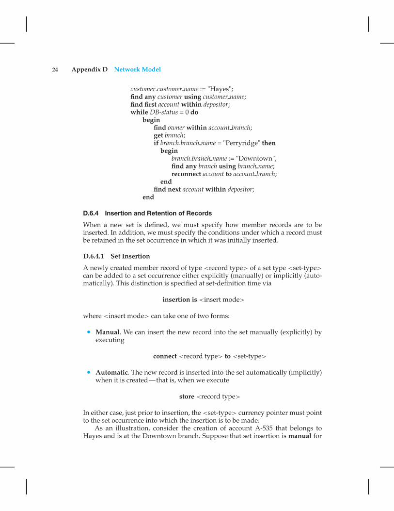
Consider the DBTG program to move all accounts of Hayes that are currentlyat the Perryridge branch to the Downtown branch:
24 Appendix D Network Model
customer.customer name := "Hayes";find any customer using customer name;find first account within depositor;while DB-status = 0 do
beginfind owner within account branch;get branch;if branch.branch name = "Perryridge" then
beginbranch.branch name := "Downtown";find any branch using branch name;reconnect account to account branch;
endfind next account within depositor;
end
D.6.4 Insertion and Retention of Records
When a new set is defined, we must specify how member records are to beinserted. In addition, we must specify the conditions under which a record mustbe retained in the set occurrence in which it was initially inserted.
D.6.4.1 Set Insertion
A newly created member record of type <record type> of a set type <set-type>
can be added to a set occurrence either explicitly (manually) or implicitly (auto-matically). This distinction is specified at set-definition time via
insertion is <insert mode>
where <insert mode> can take one of two forms:
• Manual. We can insert the new record into the set manually (explicitly) byexecuting
connect <record type> to <set-type>
• Automatic. The new record is inserted into the set automatically (implicitly)when it is created—that is, when we execute
store <record type>
In either case, just prior to insertion, the <set-type> currency pointer must pointto the set occurrence into which the insertion is to be made.
As an illustration, consider the creation of account A-535 that belongs toHayes and is at the Downtown branch. Suppose that set insertion is manual for

D.6 DBTG Set-Processing Facility 25
set type depositor and is automatic for set type account branch. The appropriateDBTG program is
branch.branch name := "Downtown";find any branch using branch name;account.account number := "A-535";account.balance := 0;store account;customer.customer name := "Hayes";find any customer using customer name;connect account to depositor;
D.6.4.2 Set Retention
There are various restrictions on how and when a member record can be removedfrom a set occurrence into which it has been inserted previously. These restrictionsare specified at set-definition time via
retention is <retention-mode>
where <retention-mode> can take one of the three forms:
1. Fixed. Once a member record has been inserted into a particular set oc-currence, it cannot be removed from that set. If retention is fixed, then, toreconnect a record to another set, we must erase that record, re-create it, andthen insert it into the new set occurrence.
2. Mandatory. Once a member record has been inserted into a particular setoccurrence, it can be reconnected to another set occurrence of only type<set-type>. It can neither be disconnected nor be reconnected to a set ofanother type.
3. Optional. No restrictions are placed on how and when a member record canbe removed from a set occurrence. A member record can be reconnected,disconnected, and connected at will.
The decision of which option to choose depends on the application. Forexample, in our banking database, the optional retention mode is appropriate forthe depositor set because we may have defunct accounts not owned by anybody.On the other hand, the mandatory retention mode is appropriate for the accountbranch set, since an account has to belong to some branch.
D.6.5 Deletion
When a record is deleted (erased) and that record is the owner of set occur-rence of type <set-type>, the best way of handling this deletion depends on thespecification of the set retention of <set-type>.

26 Appendix D Network Model
• If the retention status is optional, then the record will be deleted and everymember of the set that it owns will be disconnected. These records, however,will remain in the database.
• If the retention status is fixed, then the record and all its owned members willbe deleted. This action occurs because the fixed status means that a memberrecord cannot be removed from the set occurrence without being deleted.
• If the retention status is mandatory, then the record cannot be erased, becausethe mandatory status indicates that a member record must belong to a setoccurrence. The record cannot be disconnected from that set.
D.6.6 Set Ordering
The members of a set occurrence of type <set-type> can be ordered in a varietyof ways. These orders are specified by a programmer when the set is defined via
order is <order-mode>
where <order-mode> can be any of the following:
• first. When a new record is added to a set, it is inserted in the first position.Thus, the set is in reverse chronological order.
• last. When a new record is added to a set, it is inserted in the final position.Thus, the set is in chronological order.
• next. Suppose that the currency pointer of <set-type> points to record X. IfX is a member type, then, when a new record is added to the set, that recordis inserted in the next position following X. If X is an owner type, then, whena new record is added, that record is inserted in the first position.
• prior. Suppose that the currency pointer of <set-type> points to record X. IfX is a member type, then, when a new record is added to the set, that recordis inserted in the position just prior to X. If X is an owner type, then, when anew record is added, that record is inserted in the last position.
• system default. When a new record is added to a set, it is inserted in anarbitrary position determined by the system.
• sorted. When a new record is added to a set, it is inserted in a position thatensures that the set will remain sorted. The sorting order is specified by aparticular key value when a programmer defines the set. The programmermust specify whether members are ordered in ascending or descending orderrelative to that key.
Consider again Figure D.16, where the set occurrence of type depositor withthe owner-record customer Turner and member-record accounts A-305, A-402,and A-408 are ordered as indicated. Suppose that we add a new account A-125 tothat set. For each <order-mode> option, the new set ordering is as follows:
D.7 Mapping of Networks to Files 27
• first: {A-125, A-305, A-402, A-408}• last: {A-305, A-402, A-408, A-125}• next: Suppose that the currency pointer points to record “Turner”; then the
new set order is {A-125, A-305, A-402, A-408}• prior: Suppose that the currency pointer points to record A-402; then the new
set order is {A-305, A-125, A-402, A-408}• system default: Any arbitrary order is acceptable; thus, {A-305, A-402, A-125,
A-408} is a valid set ordering
• sorted: The set must be ordered in ascending order with account numberbeing the key; thus, the ordering must be {A-125, A-305, A-402, A-408}
D.7 Mapping of Networks to Files
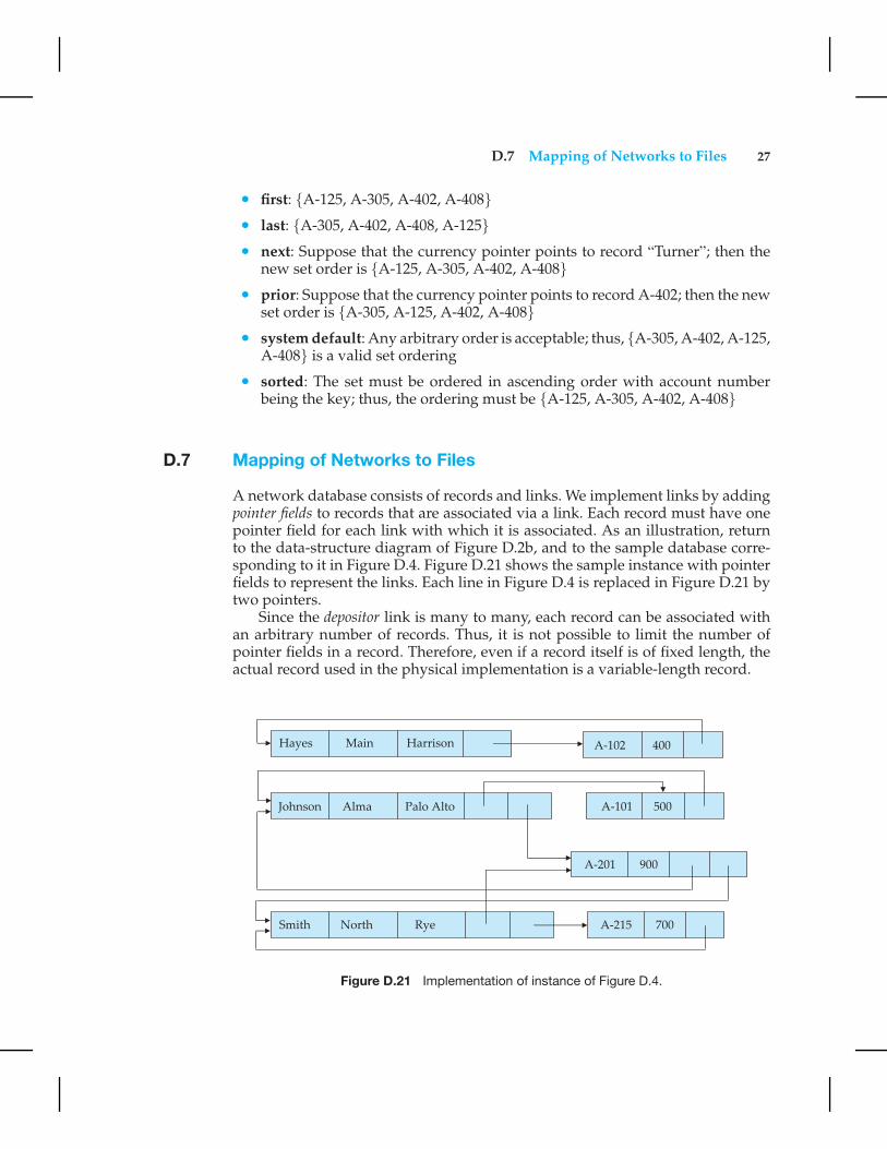
A network database consists of records and links. We implement links by addingpointer fields to records that are associated via a link. Each record must have onepointer field for each link with which it is associated. As an illustration, returnto the data-structure diagram of Figure D.2b, and to the sample database corre-sponding to it in Figure D.4. Figure D.21 shows the sample instance with pointerfields to represent the links. Each line in Figure D.4 is replaced in Figure D.21 bytwo pointers.
Since the depositor link is many to many, each record can be associated withan arbitrary number of records. Thus, it is not possible to limit the number ofpointer fields in a record. Therefore, even if a record itself is of fixed length, theactual record used in the physical implementation is a variable-length record.
Figure D.21 Implementation of instance of Figure D.4.

28 Appendix D Network Model
These complications led the architects of the DBTG model to restrict links tobe either one to one or one to many. We shall see that, under this restriction, thenumber of pointers needed is reduced, and it is possible to retain fixed-lengthrecords. To illustrate the implementation of the DBTG model, we assume that thedepositor link is one to many and is represented by the DBTG set depositor as definedhere:
set name is depositorowner is customermember is account
A sample database corresponding to this schema is in Figure D.1.An account record can be associated with only one customer record. Thus, we
need only one pointer in the account record to represent the depositor relationship.However, a customer record can be associated with many account records. Insteadof using multiple pointers in the customer record, we can use a ring structure torepresent the entire occurrence of the DBTG set depositor. In a ring structure, therecords of both the owner and member types for a set occurrence are organizedinto a circular list. There is one circular list for each set occurrence (that is, foreach record of the owner type).
Figure D.22 shows the ring structure for the example of Figure D.1. Let usexamine the DBTG-set occurrence owned by the “Johnson” record. There are twomember-type (account) records. Instead of containing one pointer to each memberrecord, the owner (Johnson) record contains a pointer to only the first memberrecord (account A-101). This member record contains a pointer to the next memberrecord (account A-201). Since the record for account A-201 is the final memberrecord, it contains a pointer to the owner record.
Figure D.22 Ring structure for instance of Figure D.1.
D.7 Mapping of Networks to Files 29
If we represent DBTG sets by using the ring structure, a record contains exactlyone pointer for each DBTG set in which it is involved, regardless of whetherit is of the owner type or member type. Thus, we can represent fixed-lengthrecords within a ring structure without resorting to variable-length records. Thisstructural simplicity is offset by added complexity in accessing records within aset. To find a particular member record of a set occurrence, we must traverse thepointer chain to navigate from the owner record to the desired member record.
The ring-structure implementation strategy for the DBTG model provided thebasis for the DBTG data retrieval facility. Recall these statements:
• find first <record type> within <set type>
• find next <record type> within <set type>
The terms first and next in these statements refer to the ordering of records givenby the ring-structure pointers. Thus, once the owner has been found, it is easy todo a find first, since all the system must do is to follow a pointer. Similarly, all thesystem must do in response to a find next is to follow the ring-structure pointer.
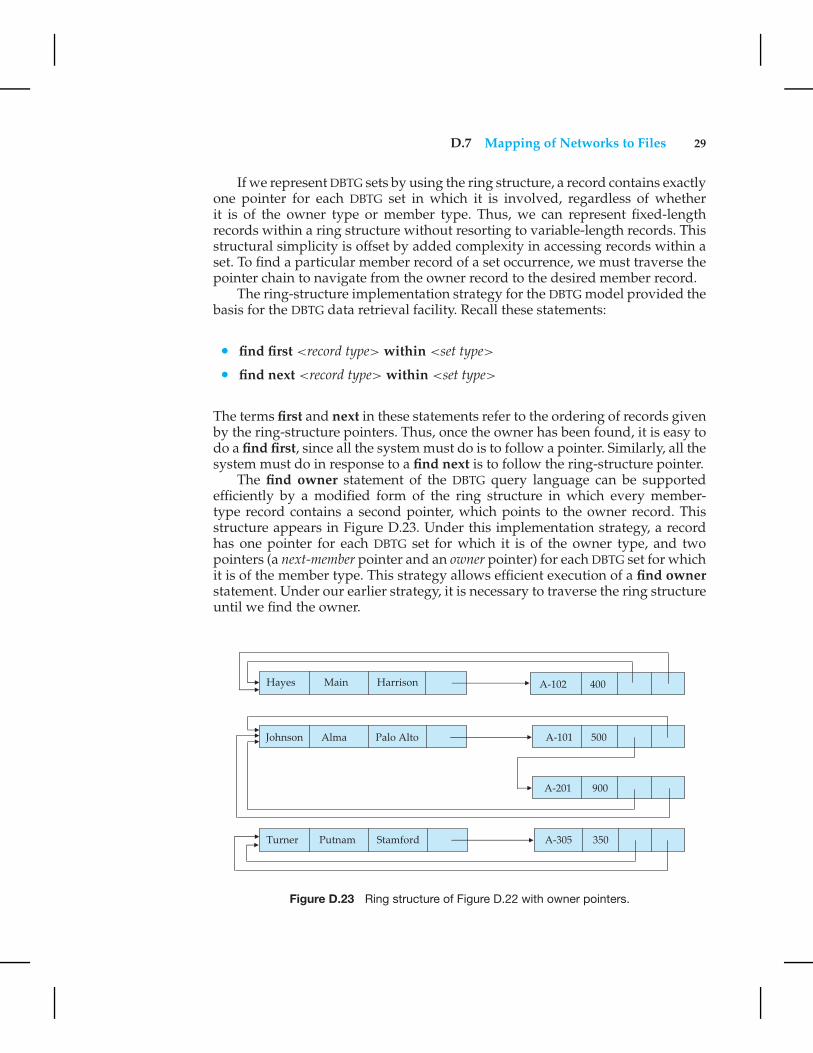
The find owner statement of the DBTG query language can be supportedefficiently by a modified form of the ring structure in which every member-type record contains a second pointer, which points to the owner record. Thisstructure appears in Figure D.23. Under this implementation strategy, a recordhas one pointer for each DBTG set for which it is of the owner type, and twopointers (a next-member pointer and an owner pointer) for each DBTG set for whichit is of the member type. This strategy allows efficient execution of a find ownerstatement. Under our earlier strategy, it is necessary to traverse the ring structureuntil we find the owner.
Figure D.23 Ring structure of Figure D.22 with owner pointers.
30 Appendix D Network Model
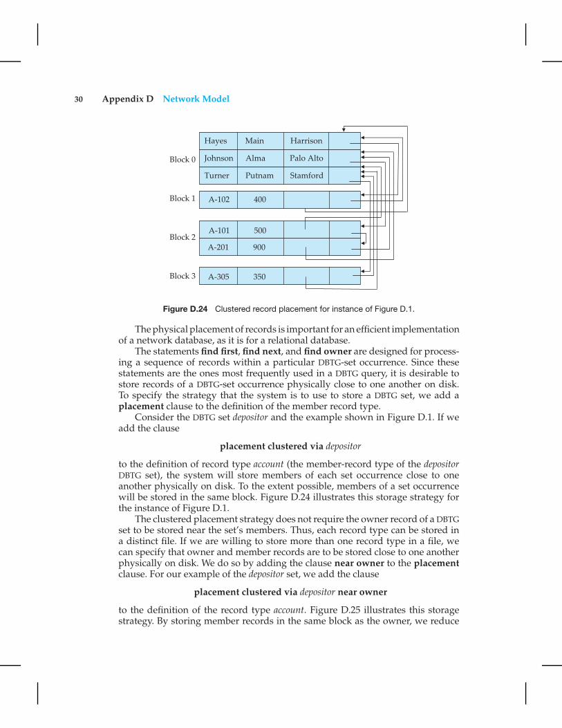
Figure D.24 Clustered record placement for instance of Figure D.1.
The physical placement of records is important for an efficient implementationof a network database, as it is for a relational database.
The statements find first, find next, and find owner are designed for process-ing a sequence of records within a particular DBTG-set occurrence. Since thesestatements are the ones most frequently used in a DBTG query, it is desirable tostore records of a DBTG-set occurrence physically close to one another on disk.To specify the strategy that the system is to use to store a DBTG set, we add aplacement clause to the definition of the member record type.
Consider the DBTG set depositor and the example shown in Figure D.1. If weadd the clause
placement clustered via depositor
to the definition of record type account (the member-record type of the depositorDBTG set), the system will store members of each set occurrence close to oneanother physically on disk. To the extent possible, members of a set occurrencewill be stored in the same block. Figure D.24 illustrates this storage strategy forthe instance of Figure D.1.
The clustered placement strategy does not require the owner record of a DBTGset to be stored near the set’s members. Thus, each record type can be stored ina distinct file. If we are willing to store more than one record type in a file, wecan specify that owner and member records are to be stored close to one anotherphysically on disk. We do so by adding the clause near owner to the placementclause. For our example of the depositor set, we add the clause
placement clustered via depositor near owner
to the definition of the record type account. Figure D.25 illustrates this storagestrategy. By storing member records in the same block as the owner, we reduce

D.8 Summary 31
Figure D.25 Record placement using clustering with the near owner option.
the number of block accesses required to read an entire set occurrence. This formof storage is analogous to the clustering file structure that we proposed earlier forthe relational model. This similarity is not surprising, since queries that requiretraversal of DBTG-set occurrences under the network model require natural joinsunder the relational model.
D.8 Summary
A network database consists of a collection of records that are connected toeach other through links. A link is an association between precisely two records.Records are organized in the form of an arbitrary graph.
A data-structure diagram is a schema for a network database. Such a dia-gram consists of two basic components: boxes, which correspond to record types,and lines, which correspond to links. A data-structure diagram serves the samepurpose as an E-R diagram; namely, it specifies the overall logical structure of thedatabase. For every E-R diagram, there is a corresponding data-structure diagram.
In the late 1960s, several commercial database systems based on the networkmodel emerged. These systems were studied extensively by the Database TaskGroup (DBTG) within the CODASYL group. In the DBTG model, only many-to-onelinks can be used. Many-to-many links are disallowed to simplify the implemen-tation. One-to-one links are represented as many-to-one links. A data-structurediagram consisting of two record types that are linked together is referred to, inthe DBTG model, as a DBTG set. Each DBTG set has one record type designated asthe owner of the set, and another record type designated as a member of the set. ADBTG set can have any number of set occurrences.
The data-manipulation language of the DBTG model consists of a number ofcommands embedded in a host language. These commands access and manipu-

32 Appendix D Network Model
late database records and links, as well as locally declared variables. For each suchapplication program, the system maintains a program work area, which containsrecord templates, currency pointers, and status flags.
The two most frequently used DBTG commands are find and get. There aremany different formats for the find command. The main distinction among them iswhether any records in the database, or records within a particular set occurrence,are to be located.
There are various mechanisms available in the DBTG model for updating in-formation in the database. They allow the creation and deletion of new records(via the store and erase operations), as well as the modification (via the modifyoperation) of the content of existing records. The connect, disconnect, and recon-nect operations provide for inserting records into and removing records from aparticular set occurrence.
When a new set is defined, we must specify how member records are to beinserted, and under what conditions they can be moved from one set occurrenceto another. A newly created member record can be added to a set occurrence eitherexplicitly or implicitly. This distinction is specified at set-definition time via theinsertion is statement with the manual and automatic insert-mode options.
There are various restrictions on how and when a member record can beremoved from a set occurrence into which it has been inserted previously. Theserestrictions are specified at set-definition time via the retention is statement withthe fixed, mandatory, and optional retention-mode options.
Implementation techniques for the DBTG model exploit the restrictions of themodel to allow the physical representation of DBTG sets without the need forvariable-length records. A DBTG set is represented by one ring structure for eachoccurrence.
Exercises
D.1 Transform the E-R diagram of Figure D.26 into a data-structure diagramassuming that the data model is
a. Network
b. DBTG
D.2 Construct a sample database for the data-structure diagram of ExerciseD.1, with 10 students and three different classes.
D.3 Show the set of variables that exists in a program work area for the data-structure diagram corresponding to the E-R diagram of Figure D.26.
D.4 Suppose that the attribute grade is added to the relationship enroll of Fig-ure D.26. Show the corresponding data-structure diagram, assuming thenetwork and DBTG model.
D.5 Transform the E-R diagram of Figure D.27 into a data-structure diagram.

Exercises 33
Figure D.26 Class enrollment E-R diagram.
D.6 Define the following terms:
a. DBTG set
b. Owner of a set
c. Member of a set
d. Set occurrence
D.7 Explain why a member record of a set occurrence cannot participate inmore than one occurrence of the set at any point.
D.8 Suppose that the find owner statement is not provided as part of the DBTGquery language. Is it still possible to answer the set of queries? Explainyour answer.
D.9 The DBTG find statement does not allow specification of predicates.
a. Discuss the drawbacks of this limitation.
b. Suggest a modification to the language to overcome this difficulty.
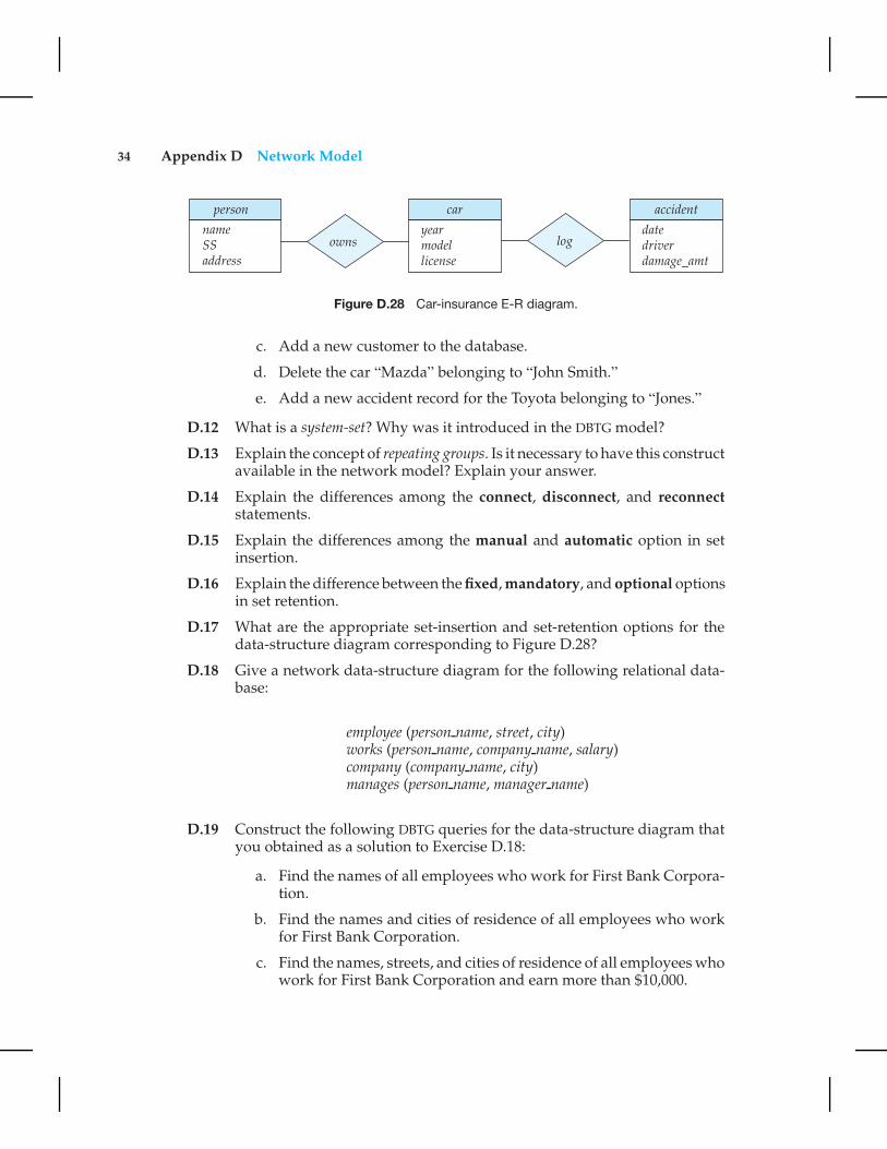
D.10 Transform the E-R diagram of Figure D.28 into a data-structure diagram,assuming the DBTG model.
D.11 For the data-structure diagram corresponding to the E-R diagram of Fig-ure D.28, construct the following DBTG queries:
a. Find the total number of people whose car was involved in anaccident in 1993.
b. Find the total number of accidents in which the cars belonging to“John Smith” were involved.
Figure D.27 Parent–child E-R diagram.
34 Appendix D Network Model
Figure D.28 Car-insurance E-R diagram.
c. Add a new customer to the database.
d. Delete the car “Mazda” belonging to “John Smith.”
e. Add a new accident record for the Toyota belonging to “Jones.”
D.12 What is a system-set? Why was it introduced in the DBTG model?
D.13 Explain the concept of repeating groups. Is it necessary to have this constructavailable in the network model? Explain your answer.
D.14 Explain the differences among the connect, disconnect, and reconnectstatements.
D.15 Explain the differences among the manual and automatic option in setinsertion.
D.16 Explain the difference between the fixed, mandatory, and optional optionsin set retention.
D.17 What are the appropriate set-insertion and set-retention options for thedata-structure diagram corresponding to Figure D.28?
D.18 Give a network data-structure diagram for the following relational data-base:
employee (person name, street, city)works (person name, company name, salary)company (company name, city)manages (person name, manager name)
D.19 Construct the following DBTG queries for the data-structure diagram thatyou obtained as a solution to Exercise D.18:
a. Find the names of all employees who work for First Bank Corpora-tion.
b. Find the names and cities of residence of all employees who workfor First Bank Corporation.
c. Find the names, streets, and cities of residence of all employees whowork for First Bank Corporation and earn more than $10,000.
Bibliographical Notes 35
d. Find all employees who live in the city where the company theywork for is located.
e. Find all employees who live in the same city and on the same streetas their managers.
f. Find all employees in the database who do not work for First BankCorporation.
g. Find all employees in the database who earn more than every em-ployee of Small Bank Corporation.
h. Assume that the companies can be located in several cities. Find allcompanies located in every city in which Small Bank Corporationis located.
i. Find all employees who earn more than the average salary of em-ployees who work in their companies.
j. Find the company that employs the most people.
k. Find the company that has the smallest payroll.
l. Find those companies that pay higher salaries, on average, than theaverage salary at First Bank Corporation.
m. Modify the database such that Jones now lives in Newtown.
n. Give all employees of First Bank Corporation a 10 percent raise.
o. Give all managers in the database a 10 percent raise.
p. Give all managers in the database a 10 percent raise, unless theresulting salary would be greater than $100,000; if it would be, giveonly a 3 percent raise.
q. Delete all employees of Small Bank Corporation.
D.20 Give a network data-structure diagram for the following relational data-base:
course (course name, room, instructor)enrollment (course name, student name, grade)
Also give an example implementation of an instance of this database.
Bibliographical Notes
In the late 1960s, several commercial database systems emerged that relied on thenetwork model. The most influential of these systems were the Integrated DataStore (IDS) system, which was developed in General Electric under the guidance ofCharles Bachman [Bachman and Williams 1964], and Associate PL/I (APL) [Dodd

36 Appendix D Network Model
1969]. These and other systems were studied extensively by the DBTG within theCODASYL group that earlier set the standard for COBOL. This study resulted inthe first database standard specification, called the CODASYL DBTG 1971 report[CODASYL 1971]. Since then, a number of changes have been suggested to thatreport, including [CODASYL 1978].
The concept of data-structure diagrams was introduced by Bachman [1969].The original presentation of data-structure diagrams used arrows to point fromowner to member record types. This presentation corresponds to the physicalpointer implementation. We have used the arrows pointing from member toowner record types to be consistent with our presentation of the E-R model. Thesame convention is used by Ullman [1988].
Implementation and design issues concerning the DBTG model are discussedby Schenk [1974], Gerritsen [1975], Dahl and Bubenko [1982], and Whang et al.[1982]. Discussions concerning the view level (the external level) of DBTG areoffered by Zaniolo [1979a, 1979b] and Clemons [1978, 1979]. A high-level querylanguage for the network model is proposed by Bradley [1978]. Translation ofnetwork queries to relational queries is discussed by Katz and Wong [1982].Taylor and Frank [1976] is a survey paper on the DBTG model.