NETWORK ALL YOUR HVAC EQUIPMENT - Zonex Systems
89
NETWORK ALL YOUR HVAC EQUIPMENT Monitor, update and control System Information from the mobile app Centralized DDC Communications for Stand-Alone HVAC and Zoned Modulating Systems INSTALLATION AND APPLICATIONS MANUAL PART # GENXMAN July 2021 USING WIRED THERMOSTATS
Transcript of NETWORK ALL YOUR HVAC EQUIPMENT - Zonex Systems

NETWORK ALL YOUR HVAC EQUIPMENTMonitor, update and control System Information from the mobile app
Centralized DDC Communications for Stand-Alone HVAC and Zoned Modulating Systems
INSTALLATION AND APPLICATIONS MANUALPART # GENXMAN
July 2021USING WIRED THERMOSTATS

CON
CEPT
UAL
OVE
RVIE
W
24VA
C / 4
0VA
TRAN
SFO
RMER
24VA
C / 1
00VA
TRA
NSF
ORM
ER
BYPA
SS D
AM
PER
1ZO
NE
DA
MPE
R
2ZO
NE
DA
MPE
R
3ZO
NE
DA
MPE
R
4ZO
NE
DA
MPE
R
LEAV
ING
AIR
SEN
SOR
STAT
ICPR
ESSU
RESE
NSO
R
View
and
upd
ate
all s
yste
m in
form
atio
n fro
m th
e fre
e m
obile
app
and
use
the
Syst
em D
iagn
ostic
to id
entif
y w
iring
er
rors
in se
cond
s.
GEN
X p
uts t
otal
syst
em c
ontro
l in
the
palm
of y
our h
and
Set S
ched
ules
glob
ally
lock
stat
s
mast
er te
mp se
t
syst
em d
iagn
ostic
set h
igh/
low
limi
t
seco
nd st
age d
elay
over
ride
hou
rs
prio
rity
vote
(0-3
)
unit
type
mave
rick
Call
syst
em ai
r bal
ance
temp
form
at
pass
word
Mor
ning
war
mup
Aux
Heat
Ener
gy Sa
ving
s mod
e
Ret
urn
Air
Sup
ply
Air
LAT
Sens
or
Mod
ulat
ing
Bypa
ssD
ampe
r
Expa
nd y
our
GEN
X S
yste
mup
to 2
0 zo
nes
usin
g W
irele
ss S
tats
Acce
ss y
our c
usto
mer
s job
AN
YTIM
E fro
m A
NYW
HER
E!!!
Com
mun
icat
e to
one
or m
ultip
le V
VT ty
pe sy
stem
s fro
m th
e fre
e G
EN X
mob
ile a
pp
GEN
X -
So m
uch
mor
e th
an a
Wi-F
i Sta
t
TO A
DD
TIO
NA
LST
AN
D A
LON
E / Z
ON
ED S
YSTE
MS
* FO
R T
HE
24V
PO
WE
R, S
IZE
TH
E W
IRE
BA
SE
D O
N L
EN
GTH
OF
RU
N
NO
TE: U
SE Z
ON
EX, 2
WIR
E TW
ISTE
D P
AIR
CO
MM
UN
ICAT
ION
LIN
K
GEN
X
NE
TWO
RK
AN
D C
ON
TRO
L V
VT
SY
STE
MS
ALO
NG
WIT
H M
ULT
IPLE
STA
ND
ALO
NE
RTU
OR
SP
LIT
SY
STE
MS
FR
OM
YO
UR
MO
BIL
E D
EV
ICE
�������� ��
� �
�������
���
����
�����
�
���
���
��
�������� ��
� �
�������
���
����
�����
�
���
���
��
�������� ��
� �
�������
���
����
�����
�
���
���
��
�������� ��
� �
�������
���
����
�����
�
���
���
��
�������� ��
� �
�������
���
����
�����
�
���
���
��
�������� ��
� �
�������
���
����
�����
�
���
���
��
�������� ��
� �
�������
���
����
�����
�
���
���
��

SYSTEM OVERVIEWGEN XGEN X is a commercial modulating bypass VAV system controlling 2-20 independent zones per RTU or split system utilizing Zonex wired thermostats that communicate remotely over the Internet with our App and a phone or mobile device from ANYWHERE. GEN X RM controllers are used to expand your system to control multiple zoned or stand alone units remotely. GEN X can support up to 20 RM expansion controllers providing control of up to 400 units, zone dampers or other control points in your system, seamlessly accessed via the App, or any browser from the end user interface.
The GEN X controller is designed for Auto Changeover, bypass VAV operation for multi-stage Heat Pump (2C/3H) or Gas Electric (2C/2H) applications. The GEN X supports VAV boxes and VFD type systems.
The GEN X mobile App allows for a wide range of system control and changeover strategies, allowing the contractor to tailor the GEN X system to a specific application, remotely or on-site.
Additional features include LED status indication of all system functions, digital leaving air temperature, return air temperature and outside air temperature display, fully adjustable capacity control with on-board limit settings and optional staging strategies. Morning warm up, email/text alerts, priority votes, and air balance features are also included. An integrated clock allows for setup, night setback, vacation scheduling, globally or individually for each zone thermostat, with selectable 2 to 8 hour override, and the ability to remotely lock each thermostat in the system. Additionally a unique system tool provides the installing contractor with a simple startup diagnostic to quickly alert and identify any system wiring errors, all from the palm of your hand using the GEN X mobile App.
GEN X is recognized as the industry’s easiest commercial zone control system to install and wire. The GEN X system operates over a plenum rated 2 wire data link, along with two 24VAC power wires daisy chained from thermostat to thermostat with no home run wiring required. Communication and configuration is done through the GEN X mobile App. GEN X can control zoned systems along with standalone units or generic loads, ie. fans, pumps, lights, ect. Zonex stand alone thermostats are utilized to control stand-alone (non-zoned) HVAC equipment and a RLYX controller is utilized to control the generic loads.
3
PULL 24V POWER AND 3 WIRE TWISTED PAIRDAISY CHAINED FROM STAT TO STAT
UP TO 20 THERMOSTATS
24VAC / 40VATRANSFORMER
24VAC/100VATRANSFORMER
BYPASS DAMPER
1ZONE
DAMPER
2ZONE
DAMPER
3ZONE
DAMPER
4ZONE
DAMPER
LEAVINGAIR SENSOR
STATICPRESSURE
SENSOR
(800) 228-2966 or get a quote at www.zonexproducts.com
View and update all system information from the free mobile app and use the System Diagnostic to identify wiring errors in seconds.
GEN X puts total system control in the palm of your hand
Set Schedules
globally lock stats
master temp set
system diagnostic
set high/low limit
second stage delay
override hours
priority vote (0-3)
unit type
maverick Call
system air balance
temp format
password
Morning warmup
Aux Heat
Energy Savings mode
Daisy Chain Wiring24 VAC and
Data Link WireDaisy Chain
to each Zone Damper
ReturnAir
SupplyAir
LATSensor
ModulatingBypass
Damper
ONLY 124V - 40VATransformer
Powers up to20 Modulating Dampers
Unit Control Wires
GEN X - VVT Controller
1
2
3
Expand your GEN X System
up to 20 zones using Wireless Stats
ZONEDAMPER
ZONEDAMPER
ZONEDAMPER
WIRELESS
WIRELESS
WIRELESS
For customers that want to monitor and control HVAC systems with a wireless mobile device from ANYWHERE
Access your customers job ANYTIME from ANYWHERE!!!Communicate to one or multiple VVT type systems from the free GEN X mobile app
GEN X - So much more than a Wi-Fi Stat
� � �� � �� �
�� ��
� � � � �� � � � � � �� �
� � � � � �
� � �
� � � � �
�� ��
� � � � �� � � � � � �� �
� � � � �
� � � � �
� � �� � �� � � � �
�� ��
� � � � �� � � � � � �� �
� � � � � �
� � � � �
� � �� � �� � � � �
�� ��
� � � � �� � � � � � �� �
� � � � �
� � � � �
� � �� � �� � � � �

Quick Start and CommissioningMobile App OverviewComponent Selection GuideSequence of OperationSystem Schematic Overview
1 QUICK START AND OVERVIEW
GEN X ControllerGEN X RM Expansion ControllerRLYX Generic Load ControllerEzTouchX Zone Thermostat
2 SYSTEM COMPONENTS
GEN X ControllerGEN X ADR and FDD InstallationGEN X RM Expansion ControllerGEN X RM FDD InstallationRLYX Generic Load Controller
3 INSTALLATION INSTRUCTIONS
ID’ing Zone ThermostatsDownloading the Mobile App and Connecting to the GEN XCommissioning and Start up of the GEN XCommissioning and Syncing of the GEN X RMCommissioning and Syncing of the RLYX
4 COMMISSIONING AND START UP
EzTouchX Overview and ConfigurationEzTouchX Configuration MenuEzTouchX Advanced MenuAuxiliary Heat / Reheat / W1 First OperationSupplemental Heat – Wiring Options
5 ZONE THERMOSTAT OVERVIEW AND OPERATION
System Configuration Menu, Schedule / VacationLock, Thermostat Lock Mode, Turn Thermostat ON/OFFSystem Diagnostic, High / Low Limit, Second Stage Delay, Override HoursPriority Vote, Fan Mode, Unit Type, Set Maverick, Enable Morning Warm UpTemperature Format, Air Balance Mode, Set Stat Zone NamesChange GEN X / RM Unit Names, Configure Number of DampersConfigure Number of RM’s Attached to SystemAssign RM ID, Configure Number of RLYX Attached to SystemAssign RLYX ID, See Zone Overview, Change Alarm SettingsChange ADR SettingsExtended Menu Options
7 GEN X MOBILE APP OVERVIEW AND OPERATION
Round and Rectangular Sizing and SelectionSlaving Zone Dampers
10 ZONE DAMPERS
Slaving Bypass DampersBypass InstallationIPC – Static Pressure Controller
5-78-9101112
13141516-17
18-202122-242526
272829-323334
35-3637-3940-424344
48-495051-5253-545556565757-585960
79-8182
8384-8586-87
11 BYPASS DAMPERS
5
13
18
27
35
48
79
83
TABLE OF CONTENTS
Web-Portal LoginZone Overview and Changing Zone Thermostat TemperaturesDiagnostics Screen and Schedule / Vacation Set upChanging Temperature Format and Zone Names
8 GEN X WEB-PORTAL INSTRUCTIONS6162-6364-6667
61
Android Wireless Connection Configuration Apple Wireless Connection ConfigurationAccount Set up for Internet Connection
6 GEN X NETWORK CONNECTION AND ACCOUNT SET UP454647
45
4
9SATouchX Universal ThermostatInstallation InstructionsSATouchX Configuration and OperationSATouchX Configuration MenuSATouchX Advanced Menu
SATOUCHX THERMOSTAT INSTALLATION AND CONFIGURATION686970-7172-7576-78
68

QUICK START AND COMMISSIONINGWiring and Installation1. Install GEN X controller inside the conditioned space, in a area that is easily accessible.2. Install an Independent 24VAC/100VA transformer, wire the secondary 24VAC output to the TR1 and TR2 (IN) bottom terminal on the GEN X controller. DO NOT ground out the transformer.3. Install the Leaving air sensor (LV Air) in the supply duct, prior to the bypass. Wire the Leaving air sensor to the LV Air terminals on the GEN X controller. Install Return air sensor (RA) in the return duct, after the bypass. Wire Return air sensor to the RA terminals.(May extend sensor wire using 18/2 thermostat wiring.) (See page 19)4. Install Supply Dampers and Bypass Dampers. (See page 80)5. Wire TR1 and TR2 (OUT) top terminal from the GEN X controller to the first zone thermostat (EzTouchX) TR1 and TR2 using 18/2 thermostat wire. (See page 18.) Continue daisy chaining TR1 and TR2 on the EzTouchX to the next EzTouchX until the last EzTouchX or Standalone thermostat (SATouchX) in the system. Make sure TR1 and TR2 polarity is consistent throughout the system.6. Wire A and B from the GEN X controller using Zonex 2 wire Plenum rated twisted pair wire (Part #STPR) to the first zone thermostat (EzTouchX). (See page 18.) Continue daisy chaining from A and B on the EzTouchX to the next EzTouchX until at the last EzTouchX board or SATouchX in the system. Make sure A and B polarity is consistent throughout the system.7. Turn ON the GEN X controller, confirm that the GEN X , EzTouchX’s, and SATouchX’s (if applicable) are powered. A blue light on the GEN X controller indicates it is powered. If you do not have a blue power light confirm power at the transformer and check TR1 and TR2 wiring.
5
DAISY CHAIN 24VAC AND 3 WIRE COMMUNICATION LINK
FROM STAT TO STAT EXPANDABLE TO 20 ZONES
POWER SWITCH
24VAC IN (BOTTOM)
24VAC OUT (TOP)
TO UNIT TERMINALS
RS485 COMMUNICATION LINK
STATUS LIGHTS
C1
GEN XWIFI APP BASED CONTROLLER
ENTHERNET CONNECTION
24VAC100VA
ABGND
GNDBA
TR1
TR1
TR2
TR2 LEAVING AIR SENSOR (LVAIR)
OUTSIDE AIR SENSOR (OA)
(TOP) RETURN AIR SENSOR (RA)
(TOP) FDD
ADR
MODULATING DAMPERDM-2
MODULATING DAMPERDM-1
MODULATING DAMPERDM-3
MCRC RO
MCRC RO M
CRC RO
�� ��
� � � � �� � � � � � �� �
� � � � � �
� � � � �MCRORCAB
GND
AUXDS
COM
DS
TR1TR2
T-1
�� ��
� � � � �� � � � � � �� �
� � � � � �
� � � � �MCRORCAB
GND
T-2
�� ��
� � � � �� � � � � � �� �
� � � � � �
� � � � �MCRORCAB
GND
AUXDS
COM
DS
TR1TR2
T-3
� � �� � �� � � � �� � �� � � � � � � �� � �� �
Optional Duct Temperature monitoring (sensor is not included)
AUXDS
COM
DS
TR1TR2
Supply Air
Wiring to Communication TerminalsRed-A
Black-B
Communication wiring is polarity sensitive. Double check that the communication wiring is connect-ed to the right terminals.
QUICK START AND COMMISSIONING
6
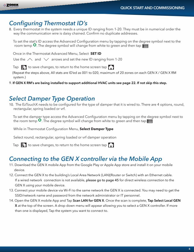
Configuring Thermostat ID’s8. Every thermostat in the system needs a unique ID ranging from 1-20. They must be in numerical order the way the communication wire is daisy chained. Confirm no duplicate addresses.
To set the stat’s ID access the Advanced Configuration menu by tapping on the degree symbol next to the room temp . The degree symbol will change from white to green and then tap
Once in the Thermostat Advanced Menu, Select SET ID Use the and arrows and set the new ID ranging from 1-20
Tap to save changes, to return to the home screen tap (Repeat the steps above, All stats are ID’ed as 001 to 020, maximum of 20 zones on each GEN X / GEN X RM system.)9. If GEN X RM’s are being installed to support additional HVAC units see page 22. If not skip this step.
Select Damper Type Operation10. The EzTouchX needs to be configured for the type of damper that it is wired to. There are 4 options, round, rectangular, spring loaded or vrf.
To set the damper type access the Advanced Configuration menu by tapping on the degree symbol next to the room temp . The degree symbol will change from white to green and then tap
While in Thermostat Configuration Menu, Select Damper Type
Select round, rectangular, spring loaded or vrf damper operation
Tap to save changes, to return to the home screen tap
Connecting to the GEN X controller via the Mobile App11. Download the GEN X mobile App from the Google Play or Apple App store and install it on your mobile device.12. Connect the GEN X to the building’s Local Area Network (LAN)(Router or Switch) with an Ethernet cable. If a wired network connection is not available, please go to page 45 for direct wireless connection to the GEN X using your mobile device.13. Connect your mobile device via Wi-Fi to the same network the GEN X is connected. You may need to get the SSID/network name and password from the network administrator or IT personnel.14. Open the GEN X mobile App and Tap Scan LAN for GEN X. Once the scan is complete, Tap Select Local GEN X at the top of the screen. A drop down menu will appear allowing you to select a GEN X controller. If more than one is displayed, Tap the system you want to connect to.

System Configuration15. Tap for System Configuration Menu; scroll down to Configure # of Thermostats and indicate how many thermostats are wired to the GEN X controller.(See page 27.)16. Tap System Diagnostic, confirm Leaving Air, Return Air, and Outdoor Air are reading temperatures. Also confirm under Thermostat Status that all Zones are Active.17. While still in System Configuration, choose Unit Type. Select Gas, Electric or Heat pump.18. See System Configuration Menu on page 48 to further configure the GEN X controller.19. Scroll to Zone Overview and select, All zones should be showing room temperatures. Tap any zone to change set point for Heating and Cooling. See page 8 on how to use the App. Adjust your cool set point and Tap at the top of the App. This will take you back to the zone overview screen. The zone room temperature should show in blue and the GEN X controller should be energized G (Green) and Y1 (Yellow) lights confirming cool call operation. Satisfy all zones calling for cooling and repeat the steps above for a heat call and confirm W1 (Red) light or Y1 (Yellow) and G (Green) lights for Heat pump operation.20. Wire the GEN X controller to the RTU or split system. (See page 20).21. Make a cool call from each zone thermostat and check register to ensure each damper opens and closes as you make and satisfy calls.
QUICK START AND COMMISSIONING
7
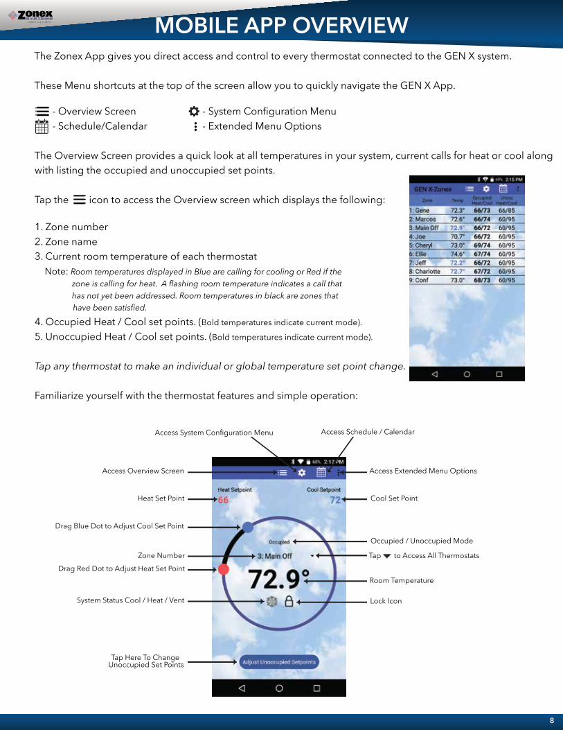
The Zonex App gives you direct access and control to every thermostat connected to the GEN X system.
These Menu shortcuts at the top of the screen allow you to quickly navigate the GEN X App.
- Overview Screen - System Configuration Menu - Schedule/Calendar - Extended Menu Options
The Overview Screen provides a quick look at all temperatures in your system, current calls for heat or cool along with listing the occupied and unoccupied set points.
Tap the icon to access the Overview screen which displays the following:
1. Zone number2. Zone name3. Current room temperature of each thermostat Note: Room temperatures displayed in Blue are calling for cooling or Red if the zone is calling for heat. A flashing room temperature indicates a call that has not yet been addressed. Room temperatures in black are zones that have been satisfied.
4. Occupied Heat / Cool set points. (Bold temperatures indicate current mode). 5. Unoccupied Heat / Cool set points. (Bold temperatures indicate current mode).
Tap any thermostat to make an individual or global temperature set point change.
Familiarize yourself with the thermostat features and simple operation:
Cool Set Point
Occupied / Unoccupied Mode
Zone Number
Room Temperature
Lock Icon
Heat Set Point
Access Overview Screen
System Status Cool / Heat / Vent
Drag Blue Dot to Adjust Cool Set Point
Access System Configuration Menu Access Schedule / Calendar
Tap Here To Change Unoccupied Set Points
Drag Red Dot to Adjust Heat Set Point
Access Extended Menu Options
Tap to Access All Thermostats
MOBILE APP OVERVIEW
8

1. The number of thermostats in the system2. Leaving, Return and Outside air temperatures3. Main system status: displays current operation, either Cool, Heat, Vent mode or Changeover4. Number of heating and/or cooling calls.
1. Select 5-1-1 (Mon – Fri, Sat – Sun), 7 day operation or 24/7 operation2. Set Daily schedule2. Set 2nd Daily schedule (optional)3. Set vacation schedules4. Enable vacation schedules
The Extended Menu provides shortcut access to the following, by tapping on the icon:
1. System diagnostics 2. Log out of Account3. Change RM/GEN X (same system)4. Change RM/GEN X (separate system)6. Exit the App
This App provides direct system access, either on-site or remotely, putting control right in the palm of your hand. For more detailed information and operating instructions explore this GEN X manual.
5. Thermostat status: indicates if each thermostat is active (wired and communicating properly with the system),and reports any wiring errors in the system.The App is a great tool to diagnose and / or avoid potential problems with your system.
GEN X is a vote based auto changeover system that polls each thermostat every 60 seconds to determine if a zone requires cooling, heating or is satisfied. System operates on a first call, first served majority wins on changeover strategy. If the system counts more heating than cooling votes then the system will operate in the heating mode, until it detects a majority of cooling votes, at which time it will initiate a changeover cycle, energize the compressor and cooling. Dampers drive closed in the heating zones and modulate to the open position in zones calling for cooling.
System Diagnostic screen provides an overview of the system’s current conditions. Tap the icon and thenlocate and tap System Diagnostic to view the following information:
Schedule/Calendar is used to schedule occupied or unoccupied periods individually or globally for each thermostat and vacation days.Tap the icon to configure the following:
Note:
MOBILE APP OVERVIEW
9
COMPONENT SELECTION GUIDEGEN X
9
Call (
800)
228
-296
6 or
get
a q
uote
at w
ww
.zone
xpro
duct
s.com
Dai
sy C
hain
Wir
ing
24 V
AC
and
Dat
a Li
nk W
ireD
aisy
Cha
into
eac
h Zo
ne D
ampe
r
ON
LY 1
24V
- 40V
ATr
ansf
orm
erPo
wer
s up
to20
Mod
ulat
ing
Dam
pers
Uni
t C
ont
rol W
ires
GEN
X -
VVT
Con
trol
ler
1 2 3
ZON
ED
AM
PER
ZON
ED
AM
PER
ZON
ED
AM
PER
WIR
ELES
S
WIR
ELES
S
WIR
ELES
S
For c
usto
mer
s tha
t wan
t to
mon
itor a
nd c
ontro
l H
VAC
syst
ems w
ith a
wire
less
mob
ile d
evic
e fro
m A
NYW
HER
E
Acce
ss y
our c
usto
mer
s job
AN
YTIM
E fro
m A
NYW
HER
E!!!
Com
mun
icat
e to
one
or m
ultip
le V
VT ty
pe sy
stem
s fro
m th
e fre
e G
EN X
mob
ile a
pp
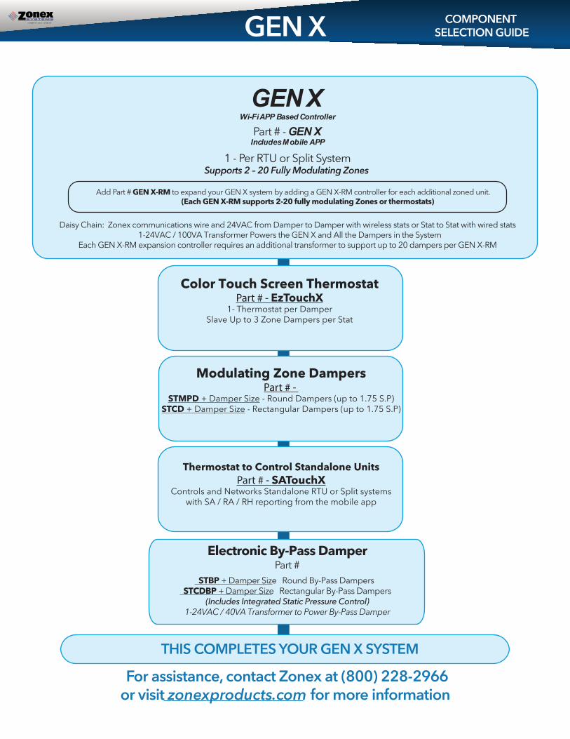
GEN XWi-Fi APP Based Controller
Part # - GEN XIncludes Mobile APP
1 - Per RTU or Split SystemSupports 2 – 20 Fully Modulating Zones
Daisy Chain: Zonex communications wire and 24VAC from Damper to Damper with wireless stats or Stat to Stat with wired stats1-24VAC / 100VA Transformer Powers the GEN X and All the Dampers in the System
Each GEN X-RM expansion controller requires an additional transformer to support up to 20 dampers per GEN X-RM
For assistance, contact Zonex at (800) 228-2966or visit zonexproducts.com for more information
THIS COMPLETES YOUR GEN X SYSTEM
Add Part # GEN X-RM to expand your GEN X system by adding a GEN X-RM controller for each additional zoned unit.(Each GEN X-RM supports 2-20 fully modulating Zones or thermostats)
Electronic By-Pass DamperPart #
STBP + Damper Size Round By-Pass Dampers STCDBP + Damper Size Rectangular By-Pass Dampers
(Includes Integrated Static Pressure Control)1-24VAC / 40VA Transformer to Power By-Pass Damper
Color Touch Screen ThermostatPart # - EzTouchX
1- Thermostat per DamperSlave Up to 3 Zone Dampers per Stat
Modulating Zone DampersPart # -
STMPD + Damper Size - Round Dampers (up to 1.75 S.P)STCD + Damper Size - Rectangular Dampers (up to 1.75 S.P)
Thermostat to Control Standalone UnitsPart # - SATouchX
Controls and Networks Standalone RTU or Split systemswith SA / RA / RH reporting from the mobile app

Vote Based Auto Changeover Bypass VAV with Programmable ThermostatsAccessed Remotely or On-site from a Phone, Mobile Device or Web Browser
GEN X / GEN X RM
GEN X controller wires to the HVAC unit with legacy style connections Y1, Y2, W1/OB, W2, G, R. Every minute the control-ler communicates to each zone thermostat via RS485 connection daisy chained along with 24VAC power wired thermo-stat to thermostat. Each zone thermostat is given a unique ID that communicates back to the GEN X controller.
The GEN X is an auto changeover, vote based VVT system. As thermostats call for heating or cooling, votes are tallied by the GEN X controller and based on the majority of votes received the HVAC unit operates in the mode of majority votes. If majority changes, the system controller will automatically initiate a changeover sequence with built in time delays to protect the equipment before changing over to the new mode of operation.
When the last calling zone is satisfied (in either heat or cool mode), the GEN X controller will terminate outputs to the HVAC unit after the next “poll”; and the blower output will de-energize (unless controller is configured for constant fan) after a 3-minute purge cycle. During the purge cycle no heat or cool calls are recognized.
The zone thermostats control and modulate zone dampers based on variance from set point to a position that will match the demand requirement. When the HVAC unit is running, if a zone thermostat is not calling or is calling for the opposite mode, its corresponding damper fully closes. When the HVAC unit is not running, the thermostats open to the Vent mode to provide ventilation if the indoor blower fan is running continuously. When configured for Reheat operation and the zone temperature drops 2° below thermostat set point, the damper modulates to approximately 40% open provid-ing airflow over electric heat strips or other supplemental heat source, the AUX terminal will energize and strip heat will energize.
While the HVAC unit is running, the capacity control LAT (leaving air temperature sensor) monitors the leaving air temperature from the HVAC unit and will cycle the HVAC unit to maintain the air temperature with a preset range to prevent coil freeze-up and premature heat exchanger failure. When the system is in the heating mode and a majority vote changes to cooling, a changeover timer begins and will run heating for 4 minutes or until heat call is satisfied and then cycle into a changeover purge. After a 3-minute purge cycle, cooling is energized until the cool call is satisfied or there is a majority vote for heat received by the GEN X controller. If all calls have been satisfied, after the 3-minute off delay, dampers will modulate to approximately 40% open position for ventilation mode.
The system fan/blower operation can be configured for ON or intermittent AUTO operation.
All Zone thermostats are wired to there respective modulating zone damper. Thermostats, scheduling and diagnostic reports to streamline system troubleshooting, are generated from the mobile App that interacts with all thermostats every minute and initiates control decisions for the system. The mobile App shall establish global or individual schedules for the system, lock thermostats individually and provide local adjustment, on site or remotely over internal Wi-Fi or the Internet. Air balance shortcuts, along with password protection, are also enabled from the App. Sleep and energy saving modes are available to extend battery life and enhance operation of the thermostats.
Voting demand strategy can be enhanced by adding Priority votes or by giving a NULL vote to individual thermostats in the system, thereby weighting certain zones more than others. Priority votes allow you to select 0, 1, 2, or 3 additional votes for a thermostat that has unusual loads, such as a conference room. A change to 0 for priority in that zone stat configuration will create a NULL vote for the HEAT/COOL and will not allow the stat to place a call for heat or cool, but will allow damper operation based on system mode of operation, HEAT/COOL/VENT.
Additional zoned systems, along with stand alone units and generic loads may be controlled with the GEN X RM or RLYX controller that supports and networks additional units. Mobile Wi-Fi or web based App streamlines installation, commis-sioning or servicing the system.
SEQUENCE OF OPERATION
11

Schematic OverviewGEN X with WIRED ZONE THERMOSTATS
DAISY CHAIN 24VAC AND 2 WIRE COMMUNICATION LINK
FROM STAT TO STAT EXPANDABLE TO 20 ZONES
GEN X CONTROLLER CONTROLS 2-20 MODULATING DAMPERS 1-24VAC/100VA TRANSFORMER POWERS ALL SUPPLY DAMPERS
DEVICE ID DESCRIPTION
MOBILE APP, Wi-Fi BASEDCONTROL BOARD C1
THERMOSTAT T1-T20 COLOR TOUCH SCREEN THERMOSTAT
SYSTEM TRANSFORMER TR124VAC/100VA TRANSFORMER (SIZED @ 5VA PER ZONE ) DAISY CHAIN STAT TO STAT
ZONE DAMPER ACTUATOR DM SUPPLIED WITH ZONE DAMPER
VISIT OUR ON-LINE CATALOG AT ZONEXPRODUCTS.COMFOR APPLICATIONS ASSISTANCE CALL 800-228-2966
SUPPLY / RETURN AIR LAT DISCHARGE SENSORS LAT
SUPPLY LAT LOCATED BEFORE THE BYPASS. RETURN LAT LOCATED AFTER THE BYPASS
RS485 COMMUNICATION LINK ZONEX 2 WIRE TWISTED PAIR
DEVICE ID DESCRIPTION
24VOLT WIRING TO EzTouchX's USE 18GA THERMOSTAT WIRE TO DAISY CHAIN THE 24VOLTS FROM STAT TO STAT
12
POWER SWITCH
24VAC IN (BOTTOM)
24VAC OUT (TOP)
TO UNIT TERMINALS
RS485 COMMUNICATION LINK
STATUS LIGHTS
C1
GEN XWIFI APP BASED CONTROLLER
ENTHERNET CONNECTION
ABGND
GNDBA
TR1
TR1
TR2
TR2 LEAVING AIR SENSOR (LVAIR)
OUTSIDE AIR SENSOR (OA)
(TOP) RETURN AIR SENSOR (RA)
(TOP) FDD
ADR
HVAC UNIT
MODULATING DAMPERDM-2
MODULATING DAMPERDM-1
MODULATING DAMPERDM-3
MCRC RO
MCRC RO M
CRC RO
�� ��
� � � � �� � � � � � �� �
� � � � � �
� � � � �MCRORCAB
GND
AUXDS
COM
DS
TR1TR2
T-1
�� ��
� � � � �� � � � � � �� �
� � � � � �
� � � � �MCRORCAB
GND
T-2
�� ��
� � � � �� � � � � � �� �
� � � � � �
� � � � �MCRORCAB
GND
AUXDS
COM
DS
TR1TR2
T-3
� � �� � �� � � � �� � �� � � � � � � �� � �� �
Optional Duct Temperature monitoring (sensor is not included)
AUXDS
COM
DS
TR1TR2
TR124VAC100VA
Controller Description
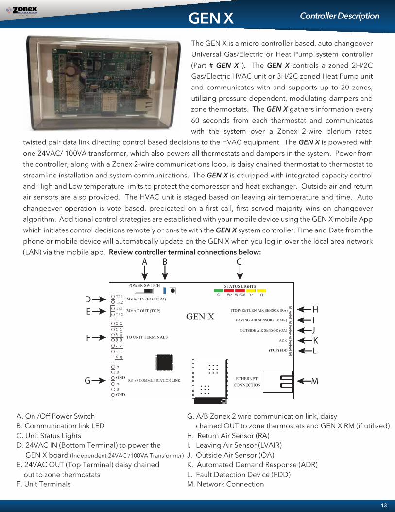
The GEN X is a micro-controller based, auto changeover Universal Gas/Electric or Heat Pump system controller (Part # GEN X ). The GEN X controls a zoned 2H/2C Gas/Electric HVAC unit or 3H/2C zoned Heat Pump unit and communicates with and supports up to 20 zones, utilizing pressure dependent, modulating dampers and zone thermostats. The GEN X gathers information every 60 seconds from each thermostat and communicates with the system over a Zonex 2-wire plenum rated
twisted pair data link directing control based decisions to the HVAC equipment. The GEN X is powered with one 24VAC/ 100VA transformer, which also powers all thermostats and dampers in the system. Power from the controller, along with a Zonex 2-wire communications loop, is daisy chained thermostat to thermostat to streamline installation and system communications. The GEN X is equipped with integrated capacity control and High and Low temperature limits to protect the compressor and heat exchanger. Outside air and return air sensors are also provided. The HVAC unit is staged based on leaving air temperature and time. Auto changeover operation is vote based, predicated on a first call, first served majority wins on changeover algorithm. Additional control strategies are established with your mobile device using the GEN X mobile App which initiates control decisions remotely or on-site with the GEN X system controller. Time and Date from the phone or mobile device will automatically update on the GEN X when you log in over the local area network (LAN) via the mobile app. Review controller terminal connections below:
GEN X
POWER SWITCH
24VAC IN (BOTTOM)
24VAC OUT (TOP)
TO UNIT TERMINALS
RS485 COMMUNICATION LINK
STATUS LIGHTS
GEN X
ETHERNET CONNECTION
A B C
DE
F
G
HIJ
M
A. On /Off Power SwitchB. Communication link LEDC. Unit Status LightsD. 24VAC IN (Bottom Terminal) to power the GEN X board (Independent 24VAC /100VA Transformer)E. 24VAC OUT (Top Terminal) daisy chained out to zone thermostatsF. Unit Terminals
TR1
TR1TR2
TR2
ABGND
ABGND
LEAVING AIR SENSOR (LVAIR)
OUTSIDE AIR SENSOR (OA)
(TOP) RETURN AIR SENSOR (RA)
(TOP) FDD
ADR KL
G. A/B Zonex 2 wire communication link, daisy chained OUT to zone thermostats and GEN X RM (if utilized)H. Return Air Sensor (RA)I. Leaving Air Sensor (LVAIR)J. Outside Air Sensor (OA)K. Automated Demand Response (ADR)L. Fault Detection Device (FDD)M. Network Connection
13
POWER SWITCH
RS485 COMMUNICATION
LINK
STATUS LIGHTSPWR / COMM LINK
A1
B1GND
GEN X RM
H
I
A
G
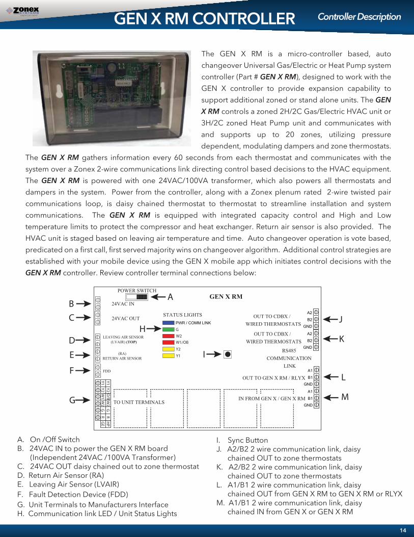
The GEN X RM is a micro-controller based, auto changeover Universal Gas/Electric or Heat Pump system controller (Part # GEN X RM), designed to work with the GEN X controller to provide expansion capability to support additional zoned or stand alone units. The GEN X RM controls a zoned 2H/2C Gas/Electric HVAC unit or 3H/2C zoned Heat Pump unit and communicates with and supports up to 20 zones, utilizing pressure dependent, modulating dampers and zone thermostats.
The GEN X RM gathers information every 60 seconds from each thermostat and communicates with the system over a Zonex 2-wire communications link directing control based decisions to the HVAC equipment. The GEN X RM is powered with one 24VAC/100VA transformer, which also powers all thermostats and dampers in the system. Power from the controller, along with a Zonex plenum rated 2-wire twisted pair communications loop, is daisy chained thermostat to thermostat to streamline installation and system communications. The GEN X RM is equipped with integrated capacity control and High and Low temperature limits to protect the compressor and heat exchanger. Return air sensor is also provided. The HVAC unit is staged based on leaving air temperature and time. Auto changeover operation is vote based, predicated on a first call, first served majority wins on changeover algorithm. Additional control strategies are established with your mobile device using the GEN X mobile app which initiates control decisions with the GEN X RM controller. Review controller terminal connections below:
GEN X RM CONTROLLER Controller Description
TO UNIT TERMINALS
A1
B1GND
A2
B2GND
A2
B2GND
J
K
L
M
OUT TO CDBX / WIRED THERMOSTATS
OUT TO GEN X RM / RLYX
IN FROM GEN X / GEN X RM
OUT TO CDBX / WIRED THERMOSTATS
24VAC IN
24VAC OUT
LEAVING AIR SENSOR (LVAIR) (TOP)
(RA)RETURN AIR SENSOR
FDD
BC
D
E
F
A. On /Off SwitchB. 24VAC IN to power the GEN X RM board (Independent 24VAC /100VA Transformer)C. 24VAC OUT daisy chained out to zone thermostatD. Return Air Sensor (RA)E. Leaving Air Sensor (LVAIR)F. Fault Detection Device (FDD) G. Unit Terminals to Manufacturers InterfaceH. Communication link LED / Unit Status Lights
I. Sync ButtonJ. A2/B2 2 wire communication link, daisy chained OUT to zone thermostatsK. A2/B2 2 wire communication link, daisy chained OUT to zone thermostats L. A1/B1 2 wire communication link, daisy chained OUT from GEN X RM to GEN X RM or RLYXM. A1/B1 2 wire communication link, daisy chained IN from GEN X or GEN X RM
14

*Board Relays are Pilot Duty
*
POWER SWITCH
24VAC IN
NOT USED
STATUS LIGHTS
NOT USED
NOT USED
PWR / COMM LINK
TR1
TR2
A1
B1GND
RLYX
BC
DG
H
A
E
F
A. On /Off SwitchB. 24VAC IN to power the RLYX board (Independent 24VAC /40VA Transformer)C. Not UsedD. Not UsedE. Not UsedF. Load TerminalsG. Communication link LED / Relay Status Lights
H. Sync Button I. Not UsedJ. Not Used K. A1/B1 2 wire communication link, daisy chained OUT from RLYX to GEN X RM or RLYXL. A1/B1 2 wire communication link, daisy chained IN from GEN X or GEN X RM
The RLYX is a communicating device equipped with 5 SPST relay terminals switched between a single Common terminal (NOT as dry contacts independent from each other). The RLYX can be used to control loads such as fans, pumps, blowers, lighting, or any load that can be operated using low voltage signals of 24VAC or less. When a relay is energized a circuit is completed between Common and the corresponding relay terminal (i.e. Common and R1, Common and R2 and so on). Status of the relays are
displayed as either ON or OFF under the Zone Overview or System Diagnostics screens of the GEN X App and LED indicators on the RLYX board. Relays will energize in the Occupied mode and de-energize in the Unoccupied mode. One Occupied and one Unoccupied event can be scheduled per day for each relay/load on either a daily basis or on 5-1-1 basis (Mon-Fri, Sat-Sun). Each relay terminal on the RLYX can be configured with its own independent schedule tailored to the needs of each load. The RLYX can also be configured with Vacation Schedules for holidays or other special events when the building will be Unoccupied during the regular schedule. If more than five loads are to be controlled then additional RLYX’s will be required. The GEN X can support up to twenty RLYX and/or GEN X RM controllers, if the application requires more than twenty RLYX and/or GEN X RM controllers then additional GEN X’s will be required.
RLYX CONTROLLER Controller Description
LOAD TERMINALS
A1
B1GND
I
J
K
L
NOT USED
OUT TO GEN X RM / RLYX
IN FROM GEN X / GEN X RM
NOT USED
15
R5R4
R3R2
R1CO
M
RS485 COMMUNICATION
LINK
R5R4R3R2R1
* * * * *
DESCRIPTION
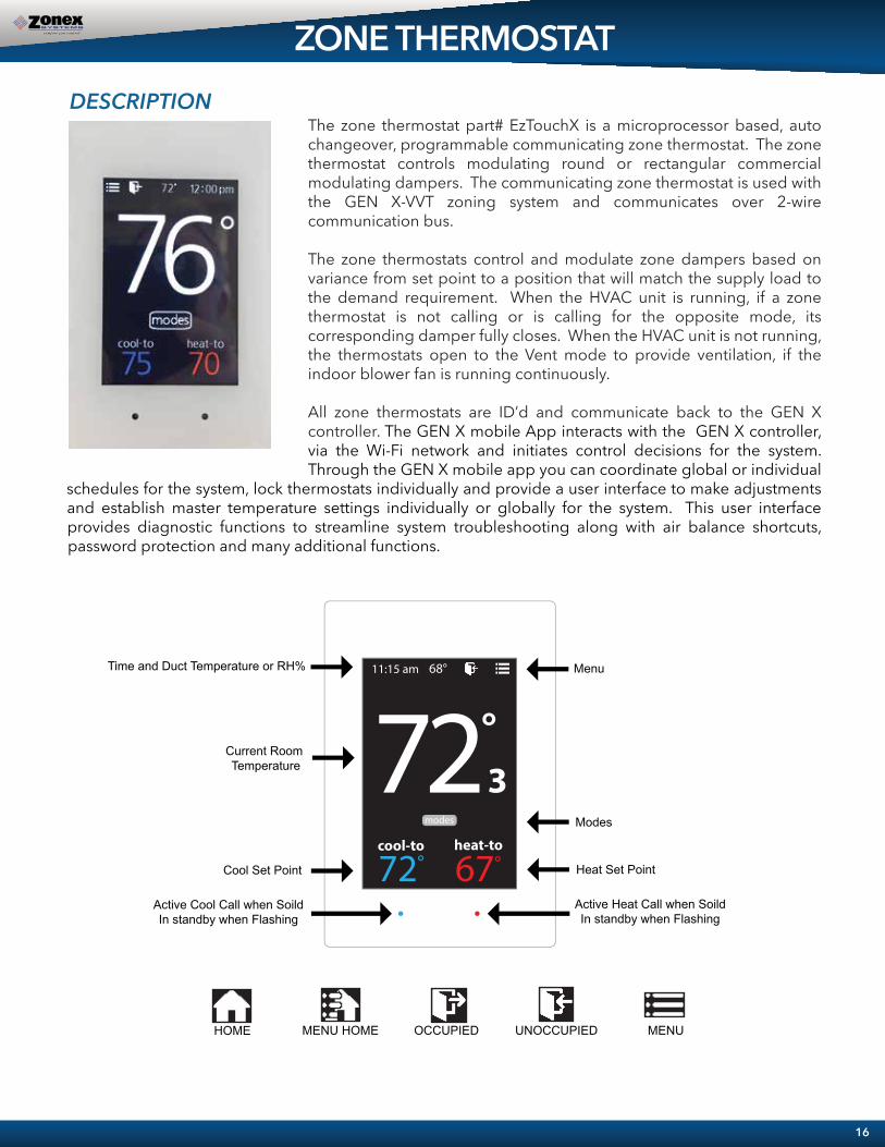
The zone thermostat part# EzTouchX is a microprocessor based, auto changeover, programmable communicating zone thermostat. The zone thermostat controls modulating round or rectangular commercial modulating dampers. The communicating zone thermostat is used with the GEN X-VVT zoning system and communicates over 2-wire communication bus.
The zone thermostats control and modulate zone dampers based on variance from set point to a position that will match the supply load to the demand requirement. When the HVAC unit is running, if a zone thermostat is not calling or is calling for the opposite mode, its corresponding damper fully closes. When the HVAC unit is not running, the thermostats open to the Vent mode to provide ventilation, if the indoor blower fan is running continuously.
All zone thermostats are ID’d and communicate back to the GEN X controller. The GEN X mobile App interacts with the GEN X controller, via the Wi-Fi network and initiates control decisions for the system. Through the GEN X mobile app you can coordinate global or individual
schedules for the system, lock thermostats individually and provide a user interface to make adjustments and establish master temperature settings individually or globally for the system. This user interface provides diagnostic functions to streamline system troubleshooting along with air balance shortcuts, password protection and many additional functions.
ZONE THERMOSTAT
16
Current Room Temperature
Modes
Cool Set Point
Menu Time and Duct Temperature or RH%
Heat Set Point
�� ��
� � � � �� � � � � � �� �
� � � � � �
� � � � �
Active Heat Call when SoildIn standby when Flashing
MENU OCCUPIED UNOCCUPIEDMENU HOMEHOME
Active Cool Call when SoildIn standby when Flashing
� � �� � �� � � � �

EzTouchX - Sequence of operationCOOL CALLWhen zone temperature rises 1° or more degrees above COOL set point, thermostat transmits COOL call to the GEN X controller. GEN X controller evaluates calls for HEAT and COOL for majority vote. If there is a majority vote for COOL, GEN X controller initiates a call for cooling and the damper modulates open. A BLUE light will flash until system is operating in the COOL mode. Once system is in COOL mode, The BLUE light will remain constant. As zone cools, thermostat will communicate with the zone damper and modulate to maintain zone comfort. When zone temperature reaches set point, damper is closed or at minimum position and EzTouchX releases call for COOL.
HEAT CALLWhen the zone temperature falls greater than 1 degree below HEAT set point, thermostat will initiate a call for HEAT. GEN X controller will evaluate all calls for HEAT and COOL in the system and if there is a majority of calls for HEAT, GEN X controller will initiate heat call and the damper modulates open. A RED light will flash until system is operating in the HEAT mode. Once system is in HEAT mode, The RED light will remain constant. As zone heat, thermostat will communicate with the zone damper and modulate to maintain zone comfort. When zone temperature reaches set point, damper is closed or at minimum position and EzTouchX releases call for HEAT.
Baseboard / Supplemental HEAT When zone thermostat is configured for BASEBOARD heat and zone temperature falls greater than 2° below HEAT set point, the thermostat will energize AUX heat and BASEBOARD heat is now operating, When calling the RED light will remain constant. When zone temperature rises to HEAT set point, thermostat will satisfy call for AUX operations.
REHEATWhen zone thermostat is configured for REHEAT operation, and the zone temperature falls greater than 2° below HEAT set point, thermostat transmits a call for REHEAT. The EzTouchX modulates the damper to 40% open and energizes AUX output REHEAT, When calling the RED light will remain constant. When zone temperature rises to HEAT set point, thermostat satisfies, releases call for AUX REHEAT and closes damper.
VENT When all calls for HEAT or COOL are satisfied, dampers will modulate to approx. 40% open and VENT will be displayed on thermostat indicating system is in ventilation mode.
17
EZTOUCHX OPERATION

Zone Damper InstallationInstall dampers into HVAC duct so damper actuators are easily accessible. Damper may be mounted in an area where the ambient temperature is between 32 and 140 degrees Fahrenheit. Round dampers should be mounted with damper actuators between 9 and 3 O’clock position.
Installing 24VAC wiringOnce GEN X controller and supply dampers are installed, install one 24VAC/100VA transformer, and wire secondary 24 volts to the TR1 / TR2 bottom terminals on GEN X controller. Using 18 ga. thermostat wire, wire TR1 / TR2 top terminals and daisy chain power wires to the first zone thermostat. Continue daisy chain wiring from first thermostat to second, third, etc., until all zone thermostats are wired with power.Note: Maintain TR1 and TR2 wiring polarity throughout the system to improve communications. DO NOT ground out the transformer.
Installing Communication Wire RS485Once power wiring is daisy chained to all zone thermostats in the system, use Zonex STPR plenum rated twisted pair communications wire to install communications loop. Install communications wire using the A and B terminals on GEN X controller and daisy chain to the first zone thermostat in the system and wire to A and B terminals. Continue daisy chain to the next thermostat using A and B terminals to the A and B of the next thermostat, repeating this process until all zone thermostats are wired into the communications loop. Communications wiring is polarity specific, if RED communications wire is on A at the GEN X controller, then RED wire is connected to A throughout the system.
INSTALLATION INSTRUCTIONS
18
DAISY CHAIN 24VAC AND 2 WIRE COMMUNICATION LINK
FROM STAT TO STAT EXPANDABLE TO 20 ZONES
POWER SWITCH
24VAC IN (BOTTOM)
24VAC OUT (TOP)
TO UNIT TERMINALS
RS485 COMMUNICATION LINK
STATUS LIGHTS
C1
GEN XWIFI APP BASED CONTROLLER
ENTHERNET CONNECTION
TR124VAC100VA
ABGND
GNDBA
TR1
TR1
TR2
TR2 LEAVING AIR SENSOR (LVAIR)
OUTSIDE AIR SENSOR (OA)
(TOP) RETURN AIR SENSOR (RA)
(TOP) FDD
ADR
MODULATING DAMPERDM-2
MODULATING DAMPERDM-1
MODULATING DAMPERDM-3
MCRC RO
MCRC RO M
CRC RO
�� ��
� � � � �� � � � � � �� �
� � � � � �
� � � � �MCRORCAB
GND
AUXDS
COM
DS
TR1TR2
T-1
�� ��
� � � � �� � � � � � �� �
� � � � � �
� � � � �MCRORCAB
GND
T-2
�� ��
� � � � �� � � � � � �� �
� � � � � �
� � � � �MCRORCAB
GND
AUXDS
COM
DS
TR1TR2
T-3
� � �� � �� � � � �� � �� � � � � � � �� � �� �
Optional Duct Temperature monitoring (sensor is not included)
AUXDS
COM
DS
TR1TR2
Supply Air
Wiring to Communication TerminalsRed-A
Black-B
Communication wiring is polarity sensitive. Double check that the communication wiring is connect-ed to the right terminals.

Install Leaving Air Temperature Sensor (LAT) to the LVAIR terminals on the GEN X controller and place the sensor in the supply duct prior to the bypass takeoff. Install Return Air Temperature Sensor (LAT) to the RA terminals on the GEN X controller and place the sensor in the return duct after the bypass takeoff.(Note: If extension of wire is needed, 18 ga. thermostat wire may be used).
HVAC UNIT
The LAT Capacity Controller protects both the air conditioner and furnace by constantly monitoring the leaving air temperature. If the air gets too cold (drops below the cool cut-out set point), it breaks the”Y” connection, disengaging the compressor. If the air gets too warm (rises above the heat cut-out set point), it breaks the “W” connection, de-energizing the furnace. To prevent short cycling, the compressor or furnace cannot re-energize for at least 4 minutes after cut-out. The heating and cooling cut-out set points can be changed by the installer from the App.
Wiring in the Leaving and Return Air Sensors to GEN X controller
POWER SWITCH
24VAC IN (BOTTOM)
24VAC OUT (TOP)
TO UNIT TERMINALS
RS485 COMMUNICATION LINK
STATUS LIGHTS
GEN XWi-Fi APP BASED CONTROLLER
ETHERNET CONNECTION
TR1
TR1
TR2
TR2
ABGND
ABGND
INSTALLATION INSTRUCTIONS
LEAVING AIR SENSOR (LVAIR)
OUTSIDE AIR SENSOR (OA)
(TOP) RETURN AIR SENSOR (RA)
(TOP) FDD
ADR
19

Wire Unit to GEN X ControllerUsing standard 18 ga. thermostat wire, connect GEN X unit outputs to HVAC unit. Standard HVACcontrol terminal designations are used, R Y1 Y2 W1(O/B) W2 G, and energize HVAC unit.
1. Gas/Electric Wiring
2. Heat Pump Wiring— O/B operation
Note: 1. Single stage systems will not use Y2 or W2 terminals for operation. Please confirm your system operation to ensure proper wiring. 2. For Heat Pump applications with Gas/Electric inputs, set system for gas operation and reset high limit on the App to 115 degrees.
GEN X / RM Output Terminals
RTU/Split System Input Terminals
GEN X / RM Output Terminals
RTU/Split System Input Terminals
POWER SWITCH
24VAC IN (BOTTOM)
24VAC OUT (TOP)
TO UNIT TERMINALS
RS485 COMMUNICATION LINK
STATUS LIGHTS
GEN XWi-Fi APP BASED CONTROLLER
ETHERNET CONNECTION
TR1
TR1
TR2
TR2
ABGND
ABGND
INSTALLATION INSTRUCTIONS
LEAVING AIR SENSOR (LVAIR)
OUTSIDE AIR SENSOR (OA)
(TOP) RETURN AIR SENSOR (RA)
(TOP) FDD
ADR
20
POWER SWITCH
24VAC IN (BOTTOM)
24VAC OUT (TOP)
TO UNIT TERMINALS
RS485 COMMUNICATION LINK
24VAC IN (BOTTOM)
24VAC OUT (TOP)
TO UNIT TERMINALS
RS485 COMMUNICATION LINK
Note: GEN X does not control the unit economizer.
24VAC100VA
21
Wiring in the Automated Demand Response (ADR) to GEN X controller
INSTALLATION INSTRUCTIONS
POWER SWITCH
24VAC IN (BOTTOM)
24VAC OUT (TOP)
TO UNIT TERMINALS
RS485 COMMUNICATION LINK
STATUS LIGHTS
ENTHERNET CONNECTION
LEAVING AIR SENSOR (LVAIR)
OUTSIDE AIR SENSOR (OA)
(TOP) RETURN AIR SENSOR (RA)
(TOP) FDD
ADR
Economizer/UnitController with
24 VAC Output for FDD
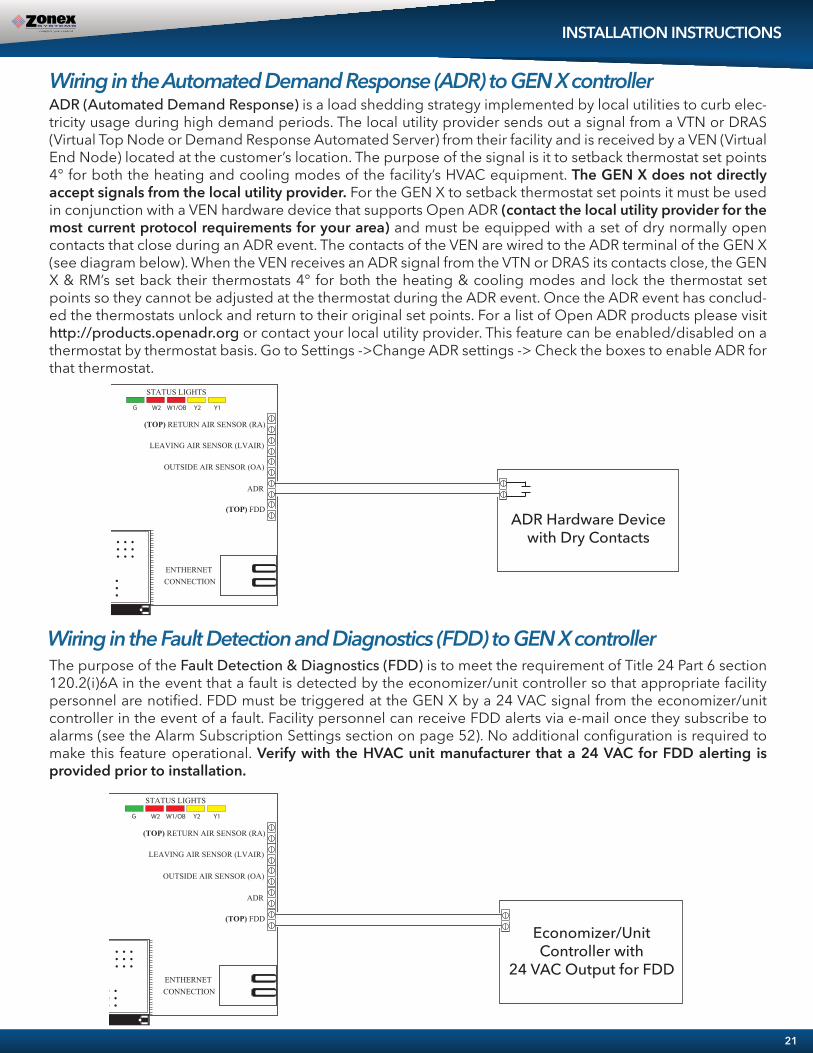
The purpose of the Fault Detection & Diagnostics (FDD) is to meet the requirement of Title 24 Part 6 section 120.2(i)6A in the event that a fault is detected by the economizer/unit controller so that appropriate facility personnel are notified. FDD must be triggered at the GEN X by a 24 VAC signal from the economizer/unit controller in the event of a fault. Facility personnel can receive FDD alerts via e-mail once they subscribe to alarms (see the Alarm Subscription Settings section on page 52). No additional configuration is required to make this feature operational. Verify with the HVAC unit manufacturer that a 24 VAC for FDD alerting is provided prior to installation.
Wiring in the Fault Detection and Diagnostics (FDD) to GEN X controller
ADR (Automated Demand Response) is a load shedding strategy implemented by local utilities to curb elec-tricity usage during high demand periods. The local utility provider sends out a signal from a VTN or DRAS (Virtual Top Node or Demand Response Automated Server) from their facility and is received by a VEN (Virtual End Node) located at the customer’s location. The purpose of the signal is it to setback thermostat set points 4° for both the heating and cooling modes of the facility’s HVAC equipment. The GEN X does not directly accept signals from the local utility provider. For the GEN X to setback thermostat set points it must be used in conjunction with a VEN hardware device that supports Open ADR (contact the local utility provider for the most current protocol requirements for your area) and must be equipped with a set of dry normally open contacts that close during an ADR event. The contacts of the VEN are wired to the ADR terminal of the GEN X (see diagram below). When the VEN receives an ADR signal from the VTN or DRAS its contacts close, the GEN X & RM’s set back their thermostats 4° for both the heating & cooling modes and lock the thermostat set points so they cannot be adjusted at the thermostat during the ADR event. Once the ADR event has conclud-ed the thermostats unlock and return to their original set points. For a list of Open ADR products please visit http://products.openadr.org or contact your local utility provider. This feature can be enabled/disabled on a thermostat by thermostat basis. Go to Settings ->Change ADR settings -> Check the boxes to enable ADR for that thermostat.
POWER SWITCH
24VAC IN (BOTTOM)
24VAC OUT (TOP)
TO UNIT TERMINALS
RS485 COMMUNICATION LINK
STATUS LIGHTS
ENTHERNET CONNECTION
LEAVING AIR SENSOR (LVAIR)
OUTSIDE AIR SENSOR (OA)
(TOP) RETURN AIR SENSOR (RA)
(TOP) FDD
ADR
ADR Hardware Devicewith Dry Contacts

INSTALLATION INSTRUCTIONSWiring the GEN X to the GEN X RMWith the GEN X controller installed, if you have additional zoned RTU’s or Split systems, install the GEN X RM expansion controller using the Zonex 2-wire twisted pair communication wire. Wire from the Gen X A, and B out to the GEN X RM A1 and B1 (IN) on the GEN X RM controller as shown below. If there are multiple GEN X RM’s or RLYX’s in the system, continue the Zonex 2-wire twisted pair in a daisy chain fashion from the GEN X RM to the next GEN X RM or RLYX. Note: Up to 20 GEN X RM’s may be daisy chained to the Gen X controller.
POWER SWITCH
RS485 COMMUNICATION
LINK
STATUS LIGHTSPWR / COMM LINK
A1
B1GND
GEN X RM
TO UNIT TERMINALS
A1
B1GND
A2
B2GND
A2
B2GND
OUT TO CDBX / WIRED THERMOSTATS
OUT TO GEN X RM / RLYX
IN FROM GEN X / GEN X RM
OUT TO CDBX / WIRED THERMOSTATS
Continue the Zonex 2-wire daisy chainfrom the GEN X RM to additional GEN X RM’s or RLYX’s
POWER SWITCH
24VAC IN (BOTTOM)
24VAC OUT (TOP)
TO UNIT TERMINALS
RS485 COMMUNICATION LINK
STATUS LIGHTS
GEN XWi-Fi APP BASED CONTROLLER
ETHERNET CONNECTION
TR1
TR1
TR2
TR2
ABGND
ABGND
24VAC IN
24VAC OUT
TR1
TR1TR2
TR2
LEAVING AIR SENSOR (LVAIR) (TOP)
(RA)RETURN AIR SENSOR
FDD
LEAVING AIR SENSOR (LVAIR)
OUTSIDE AIR SENSOR (OA)
(TOP) RETURN AIR SENSOR (RA)
(TOP) FDD
ADR
22
24VAC100VA
24VAC100VA

Zone Damper InstallationInstall dampers into HVAC duct so damper actuators are easily accessible. Damper may be mounted in an area where the ambient temperature is between 32 and 140 degrees Fahrenheit. Round dampers should be mounted with damper actuators between 9 and 3 O’clock position.
Installing 24VAC wiringOnce RM controller and supply dampers are installed, install one 24VAC/100VA transformer and wire secondary 24 volts to the TR1 / TR2 top terminals on RM controller. Using 18 ga. thermostat wire, wire TR1/ TR2 24VAC bottom terminals and daisy chain power wires to the first zone thermostat land on TR1 and TR2 (IN) terminals. Continue daisy chain wiring from TR1 and TR2 on first thermostat to TR1 and TR2 on second zone thermostat. Continue daisy chaining the wire to the third thermostat, and on until all zone thermostats are wired with power.Note: Maintain TR1 and TR2 wiring polarity throughout the system to ensure effective communications. DO NOT ground out the transformer.
Installing Communication Wire RS485Once power wiring is daisy chained to all zone thermostats in the system, use Zonex 2-TWP twisted pair communications wire to install communications loop. Install communications wire using the A2 and B2 terminals on GEN X RM controller and daisy chain to the first zone thermostat in the system wiring to A and B terminals. Continue daisy chain to the next thermostat using A and B terminals to the A and B of the next zone thermostat, repeating this process until all zone thermostats are wired into the communications loop. Communications wiring is polarity specific, if RED communications wire is on A at the RM controller, then RED wire is connected to A throughout each damper board in the system.
GEN X RM INSTALLATION INSTRUCTIONS
DAISY CHAIN 24VAC AND 2 WIRE COMMUNICATION LINK
FROM STAT TO STAT EXPANDABLE TO 20 ZONES
23
POWER SWITCH
24VAC IN
24VAC OUTSTATUS LIGHTS
PWR / COMM LINK
TR1
TR1TR2
TR2
A1
B1GND
OUT TO GEN X RM
GEN X RM
RS485 COMMUNICATION
LINK
C1
TO UNIT TERMINALS
A2
B2GND
A1
B1GND
A2
B2GND
IN FROM GEN X / GEN X RM
OUT TO CDBX / WIRED THERMOSTATS
OUT TO CDBX / WIRED THERMOSTATS
MODULATING DAMPERDM-2
MODULATING DAMPERDM-1
MODULATING DAMPERDM-3
MCRC RO
MCRC RO M
CRC RO
LEAVING AIR SENSOR (LVAIR) (TOP)
(RA)RETURN AIR SENSOR
FDD
�� ��
� � � � �� � � � � � �� �
� � � � � �
� � � � �MCRORCAB
GND
AUXDS
COM
DS
TR1TR2
T-2
�� ��
� � � � �� � � � � � �� �
� � � � � �
� � � � �MCRORCAB
GND
T-3
�� ��
� � � � �� � � � � � �� �
� � � � � �
� � � � �MCRORCAB
GND
AUXDS
COM
DS
TR1TR2
T-1
� � �� � �� � � � �� � �� � � � �� � �� � � � �
Optional Duct Temperature monitoring (sensor is not included)
AUXDS
COM
DS
TR1TR2
24VAC100VA
Supply Air
Wiring to Communication TerminalsRed-A
Black-B
Communication wiring is polarity sensitive. Double check that the communication wiring is connect-ed to the right terminals.

HVAC UNIT
Wire Unit to GEN X RM ControllerUsing standard 18 ga. thermostat wire, connect RM unit outputs to HVAC unit. Standard HVACcontrol terminal designations are used, R Y1 Y2 W1(O/B) W2 G, and energize HVAC unit.
1. Gas/Electric Wiring
2. Heat Pump Wiring— O/B operation
Note: 1. Many systems are single stage and will not use Y2 or W2 terminals for operations. Please confirm your system operation to ensure proper wiring. 2. For Heat Pump applications with Gas/Electric inputs, set system for gas operation and reset high limit on the app to 115 degrees.
Install Leaving Air Temperature Sensor (LAT) to the LVAIR terminals on the RM controller and place the sensor in the supply duct prior to the bypass takeoff. Install Return Air Temperature Sensor (LAT) to the RA terminals on the RM controller and place the sensor in the return duct after the bypass takeoff.(Note: If extension of wire is needed, 18 ga. thermostat wire may be used).
GEN X / RM Output Terminals
RTU/Split System Input Terminals
GEN X / RM Output Terminals
RTU/Split System Input Terminals
Wiring in the Leaving and Return Air Sensors to GEN X RM Controller
POWER SWITCH
24VAC IN
24VAC OUT
RS485 COMMUNICATION
LINK
STATUS LIGHTS
LEAVING AIR SENSOR (LVAIR)
RETURN AIR SENSOR (RA)
PWR / COMM LINK
TR1
TR1TR2
TR2
A1
B1GND
GEN X RM
TO UNIT TERMINALS
A1
B1GND
A2
B2GND
A2
B2GND
OUT TO CDBX / THERMOSTATS
OUT TO GEN X RM / RLYX
IN FROM GEN X / GEN X RM
OUT TO CDBX / THERMOSTATS
INSTALLATION INSTRUCTIONS
FDD
24
Note: GEN X RM does not control the unit economizer.

25
INSTALLATION INSTRUCTIONS
POWER SWITCH
24VAC IN
24VAC OUTSTATUS LIGHTS
PWR / COMM LINK
TR1
TR1TR2
TR2
OUT TO GEN X RM
GEN X RM
RS485 COMMUNICATION
LINK
C1
TO UNIT TERMINALSIN FROM GEN X / GEN X RM
OUT TO CDBX / WIRED THERMOSTATS
OUT TO CDBX / WIRED THERMOSTATSLEAVING AIR SENSOR
(LVAIR) (TOP)
(RA)RETURN AIR SENSOR
FDD
Economizer/UnitController with
24 VAC Output for FDD
The purpose of the Fault Detection & Diagnostics (FDD) is to meet the requirement of Title 24 Part 6 section 120.2(i)6A in the event that a fault is detected by the economizer/unit controller so that appropriate facility personnel are notified. FDD must be triggered at the GEN X RM by a 24 VAC signal from the economizer/unit controller in the event of a fault. Facility personnel can receive FDD alerts via e-mail once they subscribe to alarms (see the Alarm Subscription Settings section on page 58). No additional configuration is required to make this feature operational. Verify with the HVAC unit manufacturer that a 24 VAC for FDD alerting is provided prior to installation.
Wiring in the Fault Detection and Diagnostics (FDD) to GEN X RM controller

Installing 24VAC wiringOnce the RLYX controller is installed, install one 24VAC 40VA transformer and wire secondary 24 volts to the TR1 / TR2 (IN) terminals on RLYX controller. Using 18 ga. thermostat wire. Note: Maintain TR1 and TR2 wiring polarity throughout the system to ensure effective communications. DO NOT ground out the transformer.
Installing Communication Wire RS485Using Zonex 2-TWP twisted pair communications wire to install communications loop. Install communications wire using the A and B IN from GEN X / GEN X RM terminals on RLYX controller. Continue daisy chain from the OUT to GEN X RM / RYLX terminals using A and B to the A and B IN on the next GEN X RM / RYLX controller, repeating this process until controllers are wired into the communications loop. Communications wiring is polarity specific, if RED communications wire is on A at the RYLX controller, then RED wire is connected to A throughout controls communications loop.
Wiring in the 24VAC Coil Relay’s and Relay Transformer Install a second independent 24VAC 40VA transformer, using 18 ga wire run one side of the 24VAC to “COM” on the RYLX load terminals. Install a field supplied 24VAC coil relay and wire in the other leg of the 24VAC transformer to one side of the 24VAC coil on the relay or relay’s.
Now wire from “R1” off the RYLX load terminal strip using 18 ga wire to the other side of the 24VAC coil relay, this should complete the circit for the “R1” load. Repeat the steps above for any additional relay’s using load terminals “R2, R3, R4 or R5”.
Wire in the generic load power so that the relay breaks the loads power. Wire in all generic loads to meet local code requrements.
Wiring to Communication TerminalsRed-A
White-BBlack-GND
RLYX INSTALLATION INSTRUCTIONS
26
POWER SWITCH
24VAC IN
NOT USED
STATUS LIGHTS
NOT USED
NOT USED
PWR / COMM LINK
TR1
TR2
A1
B1GND
RLYX
LOAD TERMINALS
A1
B1GND
NOT USED
OUT TO GEN X RM / RLYX
IN FROM GEN X / GEN X RM
NOT USED
R5R4
R3R2
R1CO
M
RS485 COMMUNICATION
LINK
R5R4R3R2R1
TR2
R3R2R1
2-WIRE DAISY CHAIN IN FROM THE GEN X / GEN X RM
RLYX CONTROLLER IS DESIGNEDTO CONTROL GENERIC LOADS, LIKE FANS, PUMPS AND LIGHTS
DEVICE ID DESCRIPTION
LOAD CONTROL BOARD C1
**RELAY (FIELD SUPPLIED) R1- R5 24v COIL RELAY
RLYX TRANSFORMER TR1 INDEPENTENT24VAC/40VA TRANSFORMER
RELAY TRANSFORMER TR2 IND. 24VAC/40VA TRANSFORMERTO POWER THE RELAYS
VISIT OUR ON-LINE CATALOG AT ZONEXPRODUCTS.COMFOR APPLICATIONS ASSISTANCE CALL 800-228-2966
RS485 COMMUNICATION LINK ZONEX 2 WIRE TWISTED PAIR
C1
L1
L2
L1
L2
L1
L2
*
** ** **
**Isolate with a 24v Coil Relay(Field Supplied)
* * * *
*Board Relays are Pilot Duty
2-WIRE DAISY CHAIN OUT FROM THE RLYX TO GEN X RM OR RLYX

COMMISSIONING START-UPSetting ID on the EzTouchX ThermostatEach thermostat must be ID’d. Beginning with the first thermostat in the daisy chain closest to the GEN X controller, place provided white label #1 on the damper. Locate associated zone thermostat and confirm display appears on stat. If not, turn ON the GEN X and GEN X RM controllers at the ON/OFF switch located on the left hand corner of the controllers. If no display is seen, check that you have 24VAC between TR1 and TR2 on the GEN X controller and then at the thermostat.
Setting STAT ID for the Zone Thermostat
27
20
03
While in the Thermostat Advanced Menu, Select SET ID
Use the and arrows to set the new ID ranging from 1-20
Tap to save changes, to return to the home screen tap
Note: (All thermostats recieve a unique ID 01 to 20, maximum of 20 zones per GEN X and GEN X RM controllers.)
To access the Thermostat Advanced Menu: Tap on the degree symbol next to the room temp . The degree symbol will change color from white to green and then tap .
�� ��
� � � � �� � � � � � �� �
� � � � � �
� � � � �
� � �� � �� �
� � �� � �� �
� ��
� � � � �� � � � � � �� �
� � � � � �
� � �
� � � � �
� � �� � �� �
id 1select aux heat baseboard-db2select damper type roundselect temp source ductselect menu type advanced
select from menu
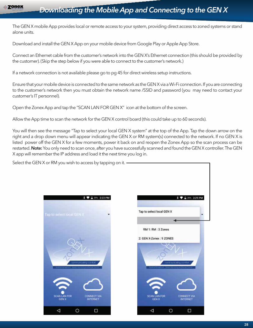
The GEN X mobile App provides local or remote access to your system, providing direct access to zoned systems or stand alone units.
Download and install the GEN X App on your mobile device from Google Play or Apple App Store.
Connect an Ethernet cable from the customer’s network into the GEN X’s Ethernet connection (this should be provided by the customer). (Skip the step below if you were able to connect to the customer’s network.)
If a network connection is not available please go to pg 45 for direct wireless setup instructions.
Ensure that your mobile device is connected to the same network as the GEN X via a Wi-Fi connection. If you are connecting to the customer’s network then you must obtain the network name /SSID and password (you may need to contact your customer’s IT personnel).
Open the Zonex App and tap the “SCAN LAN FOR GEN X” icon at the bottom of the screen.
Allow the App time to scan the network for the GEN X control board (this could take up to 60 seconds).
You will then see the message “Tap to select your local GEN X system” at the top of the App. Tap the down arrow on the right and a drop down menu will appear indicating the GEN X or RM system(s) connected to the network. If no GEN X is listed power off the GEN X for a few moments, power it back on and reopen the Zonex App so the scan process can be restarted. Note: You only need to scan once, after you have successfully scanned and found the GEN X controller. The GEN X app will remember the IP address and load it the next time you log in.
Select the GEN X or RM you wish to access by tapping on it.
Downloading the Mobile App and Connecting to the GEN X
28

COMMISSIONING AND STARTUP
Confirm Thermostat Communications
Set Type of UnitConfirm the type of unit the GEN X is controlling: GAS, ELECTRIC, HEAT PUMP (O), or HEAT PUMP (B). Factory default for UNIT TYPE is GAS, if application is ELECTRIC or HEAT PUMP, you will need to adjust this through the mobile App. Select Unit Type in the configuration menu, tap Heat Pump O/B or Electric.
Once GEN X controller is mounted, and zone stats are ID’d the system is ready to be commissioned and started up. Turn on the GEN X controller and confirm the blue power light is ON.
Open the Gen X app, tap the for System Configuration Menu and tap Configure Number of Thermostats / Dampers. Enter the number of zones that are in the system. While still in the Configuration menu tap System Diagnostic and confirm that all the zones are showing Active under the thermostat status. If it shows Err: Check wiring / Stat ID confirm wiring is correct and check Stat ID.
29

Confirm High/Low LimitsFactory defaults for GAS/ELECTRIC units are set for 40 degrees Low Limit and 145 degrees High Limit.Heat Pump O and B machines are set for 40 degrees Low Limit and 115 degrees High Limit. These may beadjusted in the field to meet unit specification. To confirm or adjust, use the mobile app to access the configuration menu. Select High/Low Limits, tap High or Low limit and confirm limit set point.
Set Fan OperationConfiguration of FAN is set at the factory for AUTO operation. When there is a call for HEAT or COOL, fan will run. If continuous fan is required, fan will need to be configured for fan ON and will run anytime during Occupied time, and AUTO during unoccupied. To set fan mode, using the Mobile App access the configuration menu. Tap FAN mode, choose AUTO or ON.
COMMISSIONING AND STARTUP
*Check the RTU / Spilt System’s High / Low Limits and adjust them on the GEN X / GEN X-RM below the units cut out limit.
30

Confirm Cool Call and Damper Operation Open the Gen X app and go to the Zone overview screen , select Zone 1 by tapping on that zone. The Ring of Comfort screen should appear. Tap on in the middle of the ring and choose All Zones. Slide or Drag the Blue circle counter clockwise to drop the temperature below the current room temperature. Tap back on the phone to return to zone overview screen. All zones should have a current room temperature that is blinking blue, indicating a cool call. Within 2 minutes, a call for cooling will be made from GEN X controller. Confirm Y1 and G lights are on at the GEN X controller. Go to each zone and confirm damper is open and “ON” appears on thermostat display indicating an active cool call. Once all dampers are confirmed open, satisfy cooling calls at each zone thermostat. At each zone stat, raise COOL set point by using the UP button to raise the set point. Confirm “ON” disappeared and damper closes once call is satisfied. Continue to satisfy all cool calls one at a time until all calls are satisfied and dampers are closed. If damper does not close confirm power and communication wiring installation. Within 1 minute of all calls satisfying Y1 will de-energize, and a 3 minute purge follows, no calls are allowed during this time.
OVERVIEW SCREEN RING OF COMFORT ACCESS ALL THERMOSTATS
COMMISSIONING AND STARTUP
31
�� ��
� � � � �� � � � � � �� �
� � � � � �
� � � � �
� � �� � �� �

VentWith all calls satisfied all dampers modulate to VENT position, approximately 40% open, confirm stat display indicates “VENT”.
Confirm Heat Call and Damper OperationOpen the Gen X app and go to the Zone overview screen , select Zone 1 by tapping on that zone. The Ring of Comfort screen should appear. Tap on in the middle of the ring and choose All Zones. Slide or Drag the Red circle clockwise to raise the temperature above the current room temperature. Tap back on the phone to return to zone overview screen. All zones should have a current room temperature that is blinking Red indicating a heat call. Within 2 minutes a call for heating will be made from GEN X controller and confirm W1(Y1 for HP) light is on at the GEN X controller. Go to each zone and confirm damper is open and “ON” appears on thermostat display indicating an active heat call. Once all dampers are confirmed open, satisfy heating calls at each zone thermostat. At each zone stat, lower heat set point by using the DOWN button to lower the set point. Confirm “ON” disappears and damper closes once call is satisfied. Continue to satisfy all heat calls one at a time until all calls are satisfied and dampers are closed. If damper does not close confirm power and communication wiring installation. Within 1 minute of all calls satisfying W1 (Y1 for HP) will de-energize, and a 3 minute purge follows, no calls are allowed during this time.
COMMISSIONING AND STARTUP
32
�� ��
� � � � �� � � � � � �� �
� � � � � �
� � � � �
� � �� � �� �

Syncing the GEN X RM to the GEN X ControllerEach RM controller communicates to the GEN X over an RS-485 communications bus. GEN X is the communications hub for the system providing time clock functions along with interpreting any calls or system updates at the RM level and communicates that information to the cloud. Each RM controller must be synced with the GEN X controller to communicate and transmit information to and from the mobile App.
Connect to the GEN X via the mobile app. Go into the “System Configuration Menu” and tap “Configure Number of RM’s Attached to System”. Enter the number of GEN X RM’s wired to the GEN X controller.
While still in the “System Configuration Menu”, tap “Assign RM ID”. Enter 1 for the first GEN X RM in the system and press “OK”. When the Blue light starts flashing on the GEN X RM controller, press and hold the sync button on the GEN X RM board for 15 seconds. When the light stops flashing the sync has been completed.
Repeat the “Assign RM ID” for each additional GEN X RM in the system, making sure to increase the RM ID for each GEN X RM. For example, if you have 7 GEN X RM’s in the system they will be ID'd 1-7 in the order of how the communication wire is daisy chained.
POWER SWITCH
24VAC IN
24VAC OUT
TO UNIT TERMINALS
STATUS LIGHTS
LEAVING AIR SENSOR (LVAIR)
PWR / COMM LINK
R
TR2TR1
C
IN FROM GEN X / GEN X RM
OUT TO GEN X RM
GEN X RM
Enter number of RMs attached to the system (1-20) Each RM needs to be assigned its own ID
After assigning the RM with its IDwait for the Blue communicationlight to start blinking rapidly andthen press and hold the sync button for 15 seconds.
POWER SWITCH
24VAC IN
24VAC OUT
RS485 COMMUNICATION
LINK
STATUS LIGHTSPWR / COMM LINK
TR1
TR1TR2
TR2
A1
B1GND
GEN X RM
TO UNIT TERMINALS
A1
B1GND
A2
B2GND
A2
B2GND
OUT TO CDBX / THERMOSTATS
OUT TO GEN X RM
IN FROM GEN X / GEN X RM
OUT TO CDBX / THERMOSTATS
COMMISSIONING AND STARTUP
LEAVING AIR SENSOR (LVAIR)
RETURN AIR SENSOR (RA)
FDD
33

RS485 COMMUNICATION
LINK
LEAVING AIR SENSOR (LVAIR)
RETURN AIR SENSOR (RA)
GND
RXTX
Syncing the RLYX to the GEN X ControllerEach RLYX controller communicates to the GEN X over an RS-485 communications bus. GEN X is the communications hub for the system providing time clock functions along with interpreting any calls or system updates at the RLYX and communicates that information to the cloud. Each RLYX controller must be synced with the GEN X controller to communicate and transmit information to and from the mobile App.
Connect to the GEN X via the mobile app. Go into the “System Configuration Menu” and tap “Configure Number of RLYX’s Attached to System”. Enter the number of RLYX’s wired to the GEN X controller.
While still in the “System Configuration Menu”, tap “Assign RLYX ID”. Enter 1 for the first RLYX in the system and press “OK”. When the Blue light starts flashing on the RLYX controller, press and hold the sync button on the RLYX board for 15 seconds. When the light stops flashing the sync has been completed.
Repeat the “Assign RLYX ID” for each additional RLYX in the system, making sure to increase the RLYX ID for each RLYX. For example, if you have 3 RLYX’s in the system they will be ID'd 1-3 in the order of how the communication wire is daisy chained.
POWER SWITCH
24VAC IN
24VAC OUT
TO UNIT TERMINALS
STATUS LIGHTS
LEAVING AIR SENSOR (LVAIR)
PWR / COMM LINK
R
TR2TR1
C
IN FROM GEN X / GEN X RM
OUT TO GEN X RM
GEN X RM
Enter number of RLYX’s attached to the system (1-20) Each RLYX needs to be assigned its own ID
After assigning the RLYX with its IDwait for the Blue communicationlight to start blinking rapidly andthen press and hold the sync button for 15 seconds.
COMMISSIONING AND STARTUP
34
POWER SWITCH
24VAC IN
NOT USED
STATUS LIGHTS
NOT USED
NOT USED
PWR / COMM LINK
TR1
TR2
A1
B1GND
RLYX
LOAD TERMINALS
A1
B1GND
NOT USED
OUT TO GEN X RM / RLYX
IN FROM GEN X / GEN X RM
NOT USED
R5R4
R3R2
R1CO
M
RS485 COMMUNICATION
LINK
R5R4R3R2R1
C1
* * * * *

EzTouchX CONFIGURATION
EzTouch CONFIGURATION
35
RS485 COMMUNICATION
LINK
LEAVING AIR SENSOR (LVAIR)
RETURN AIR SENSOR (RA)
GND
RXTX
Current Room Temperature
Modes
Cool Set Point
Menu Time, Duct Temperature or RH%
Heat Set Point
Addressing Zone ThermostatsEvery thermostat in the system needs a unique ID ranging from 1-20. They must be in numerical order the way the communication wire is daisy chained. Confirm no duplicate addresses.
To set the stat’s ID access the Advanced Configuration menu by tapping on the degree symbol next to the room temp . The degree symbol will change from white to green and then tap
Once in the Thermostat Advanced Menu, Select SET ID
Use the and arrows and set the new ID ranging from 1-20
Tap to save changes, to return to the home screen tap
�� ��
� � � � �� � � � � � �� �
� � � � � �
� � � � �
Active Heat Call when SoildIn standby when Flashing
MENU OCCUPIED UNOCCUPIEDMENU HOMEHOME
Active Cool Call when SoildIn standby when Flashing
� � �� � �� � � � �
Select Damper TypeThe EzTouchX needs to be configured for the type of damper that it is wired to. There are 4 options, round, rectangular, spring loaded or vrf.
To set the damper type access the Advanced Configuration menu by tapping on the degree symbol next to the room temp . The degree symbol will change from white to green and then tap
While in Thermostat Configuration Menu, Select Damper Type
Select round, rectangular, spring loaded or vrf damper operation
Tap to save changes, to return to the home screen tap

Adjusting Set PointsThe Heat or Cool set points are displayed at the bottom of the screen. To adjust the set points, tap on the heat-to or cool-to temperatures; the set points will be displayed on the screen.
Use the and arrows over the flame/snowflake icons to set the desired heat and cool set points.
Tap to save changes
Changing ModeThe thermostats are auto changeover, but specific modes may be selected. Heat/Cool mode is the default.
System Heat/Cool - Tap on , select “Heat/Cool”. Tap to save changes System Heat Only - Tap on , select “Heat Only”. Tap to save changes
System Cool Only - Tap on , select “Cool Only”. Tap to save changes
System Off - Tap on , select “Off”. Tap to save changes
Override OperationWhen the thermostat displays the unoccupied icon a 2-hour temporary override may be initiated by tapping the “Override” will appear. When additional override time is required, tap the unoccupied icon again.
Auxiliary Heat / ReheatThe zone thermostat provides the following Auxiliary Heat options; Baseboard, Baseboard W1 and Reheat (see figure on the following page for more details) with configurable dead band of 2°, 3°, or 4°. Note: Reheat has a fixed 2° dead band. And when using in duct electric strip heater, an airflow proving switch is required for safe operation.
Configuration of Auxiliary Heat/Reheat is accomplished by selecting “SELECT AUX HEAT” function in the Advanced Menu. To access the Advanced Menu tap the degree symbol of the room temperature (the degree symbol should change color to green) then tap the in the upper right corner of the thermostat, Tap “Select Aux Heat”, Select the desired Auxiliary Heat/Reheat and dead band (2°, 3°, or 4°). Tap on to save desired settings. To return to the home screen tap
� � � � �
� � � � �
� � � � �
� � � � �
EzTouchX CONFIGURATION
36
Display Temperature CalibrationThermostats are calibrated at the factory and should require no further adjustment. However, the display space tempera-ture may be field calibrated by the following procedure:
To access the Thermostat Configuration Menu: Tap
While in Thermostat Configuration Menu, Select Calibrate Display
Use the and arrows to calibrate the thermostat display to a external temperature probe temperature reading.
Tap to save changes, to return to the home screen tap

EzTouchX CONFIGURATION MENU
37
�� ��
� � � � �� � � � � � �� �
� � � � � �
THERMOSTAT USER MENUTo access the Thermostat User Menu: Tap
The THERMOSTAT USER MENU allows you to:Select Occupied Light Select Unoccupied Light Set Display Accuracy Calibrate Display Temperature F/C (view only) Current Schedule (view only) Time & Date (view only)
� � �� � �� �
SELECT OCCUPIED LIGHT
While in Thermostat Configuration Menu, Select Occupied Light
Select the desired brightness.
Tap to save changes, to return to the home screen tap
Note: If “off” is selected, just touch stat to wake it up.
� � �� � �� �
SELECT UNOCCUPIED LIGHT
While in Thermostat Configuration Menu, Select Unoccupied Light
Select the desired brightness.
Tap to save changes, to return to the home screen tap
Note: If “off” is selected, just touch stat to wake it up.
The brightness of the thermostat during unoccupied mode is adjustable from 100% down to off .
� � �� � �� �
The brightness of the thermostat during occupied mode is adjustable from 100% down to off .
� � �� � �� �
� ��
� � � � �� � � � � � �� �
� � � � � �
� � �
� � � � �
� � �� � �� �
select occupied light 100select unoccupied light 100set display accuracy 1°calibrate display 67temperature F/C fahrenheit
select from menu
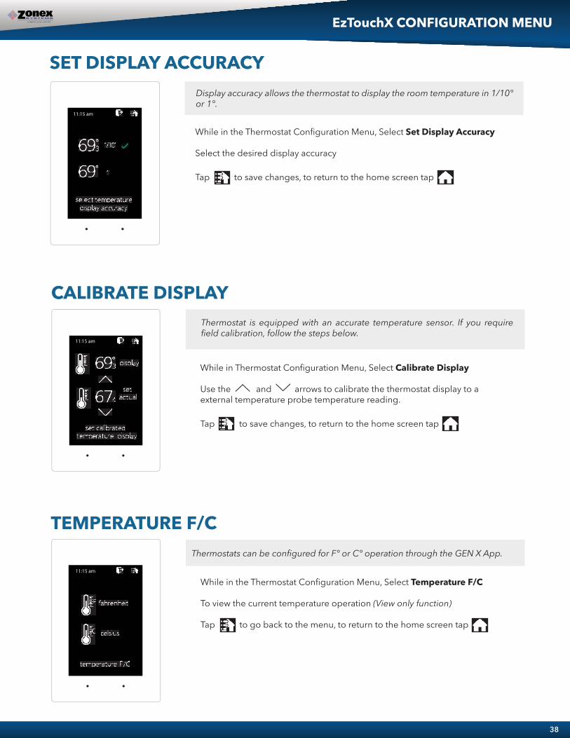
38
EzTouchX CONFIGURATION MENU
Display accuracy allows the thermostat to display the room temperature in 1/10° or 1°.
SET DISPLAY ACCURACY
While in the Thermostat Configuration Menu, Select Set Display Accuracy
Select the desired display accuracy
Tap to save changes, to return to the home screen tap
CALIBRATE DISPLAYThermostat is equipped with an accurate temperature sensor. If you require field calibration, follow the steps below.
While in Thermostat Configuration Menu, Select Calibrate Display
Use the and arrows to calibrate the thermostat display to a external temperature probe temperature reading.
Tap to save changes, to return to the home screen tap
TEMPERATURE F/CThermostats can be configured for F° or C° operation through the GEN X App.
While in the Thermostat Configuration Menu, Select Temperature F/C
To view the current temperature operation (View only function)
Tap to go back to the menu, to return to the home screen tap
� � �� � �� �
� � �� � �� �
� � �� � �� �

39
EzTouchX CONFIGURATION MENU
TIME & DATEView the current time and date, given by the Gen X system.
While in the Thermostat Configuration Menu, Select Time & Date
To view the current time and date on the Gen X system (View only function)
Tap to go back to the menu, to return to the home screen tap
� � �� � �� � � � �
CURRENT SCHEDULEView the current thermostat schedule, given by the Gen X system
While in the Thermostat Configuration Menu, Select Current Schedule
This allows you to view the schedule for that zone. Changes to the schedule are done through the GEN X App. (View only function)
Tap to go back to the menu, to return to the home screen tap
� � �� � �� � � � �
-
� � �� � �� �
� � �� � �� �

40
While in the Thermostat Advanced Menu, Select Aux Heat
Select the desired auxiliary heat operation and dead band
Tap to save changes, to return to the home screen tap
Note: Reheat has a fixed 2° dead band.
While in the Thermostat Advanced Menu, Select SET ID
Use the and arrows to set the new ID ranging from 1-20
Tap to save changes, to return to the home screen tap
Note: (All thermostats recieve a unique ID 01 to 20, maximum of 20 zones per GEN X and GEN X RM controllers.)
THERMOSTAT ADVANCED MENUTo access the Thermostat Advanced Menu: Tap on the degree symbol next to the room temp . The degree symbol will change color from white to green and then tap .
The THERMOSTAT ADVANCED MENU allows you to:Set ID Select damper type Select Menu Type Select Aux Heat Temp Source Diagnostic
STAT IDEvery thermostat in the system needs a unique ID. They must be ID’ed in numerical order the way the communication wire is daisy chained. No duplicate addresses.
The zone thermostat provides the following Auxiliary Heat options; Baseboard, Baseboard W1 and Reheat with configurable dead band of 2°, 3°, or 4°.
SELECT AUX HEAT
20
03
� � �� � �� �
� ��
� � � � �� � � � � � �� �
� � � � � �
� � �
� � � � �
�� ��
� � � � �� � � � � � �� �
� � � � � �
� � � � �
� � �� � �� �
� � �� � �� �
� � �� � �� �
EzTouchX ADVANCED MENU
� � �� � �� �
� ��
� � � � �� � � � � � �� �
� � � � � �
� � �
� � � � �
� � �� � �� �
id 1select aux heat baseboard-db2select damper type roundselect temp source ductselect menu type advanced
select from menu

41
SELECT DAMPER TYPE
While in the Thermostat Advanced Menu, Select Menu Type
Select user to hide the advanced optionsSelect advanced to show the advanced options under the user menu
Tap to save changes, to return to the home screen tap
Menu type will allow you to see the advanced menu options under the user menu when advanced is selected.
SELECT MENU TYPE
While in the Thermostat Advanced Menu, Select Damper Type
Select round, rectangular, spring loaded or vrf damper operation
Tap to exit diagnostic screen, to return to the home screen tap
� � �� � �� �
� � �� � �� � � � �
EzTouchX ADVANCED MENU
� � �� � �� �
� ��
� � � � �� � � � � � �� �
� � � � � �
� � �
� � � � �
� � �� � �� �
set damper type
roundrectangularspring loadedvrf
TEMP SOURCETemp source allows the thermostat to display the outside air temperature, supply air duct or relative humidity at the top on the home screen. A LAT sensor needs to be installed to report this reading. It will read 00 if no sensor is installed.
While in the Thermostat Advanced Menu, Select Temp Source
Select outside, duct, humidity or no display to diplay or not display the duct temperature
Tap to save changes, to return to the home screen tap
� � �� � �� �
outsideducthumidityno display
The EzTouchX needs to be configured for the type of damper that it is wired to. There are 4 options, round, rectangular, spring loaded or vrf.

42
DIAGNOSTIC
While in the Thermostat Advanced Menu, Select Diagnostic
Tap damper to confirm closed/open operationTap aux relay to confirm it energizes and de-energizesTap blue led to confirm the blue led illuminatesTap red led to confirm the red led illuminates
Tap to exit diagnostic screen, to return to the home screen tap
The EzTouchX Diagnostic screen will allow you to confirm communication with the GEN X controller and allow you to confirm damper, aux relay, and LED operation.� � �� � �� �
EzTouchX ADVANCED MENU

AUXILIARY HEAT/REHEAT
The zone thermostat provides the following Auxiliary Heat options; Baseboard, Baseboard W1 and Reheat (see figure on the following page for more details) with configurable dead band of 2°, 3°, or 4°. Note: Reheat has a fixed 2° dead band.
Baseboard: the thermostat’s auxiliary output will energize when the room temperature drops 2° - 4° below the heat set point. Auxiliary heat operations will remain energized until the heat call is satisfied.
Baseboard W1: the auxiliary output will energize before the unit heater at 1° below heat set point. When the room temperature drops 2° - 4° below set point the thermostat will send a heat call to the unit heater. Auxiliary heat operations will remain energized until the heat call is satisfied.
Reheat: when the zone temperature drops 2° below the heat set point the damper will modulate to approximately 40% providing air flow over the electric heat strips, the AUX terminal will energize, and strip heat will provide reheat.Note: When using in duct electric strip heater, an airflow proving switch is required for safe operation.
Configuration of Auxiliary Heat/Reheat is accomplished by selecting “SELECT AUX HEAT” function in the Advanced Menu. To access the Advanced Menu tap the degree symbol of the room temperature (the degree symbol should change color to green) then tap the in the upper right corner of the thermostat, see Fig 1. Tap “Select Aux Heat”, see Fig 2. Select the desired Auxiliary Heat/Reheat and dead band (2°, 3°, or 4°) see Fig 3. Tap on to save desired settings. To return to the home screen tap
Fig 1 Fig 2 Fig 3
Home Screen Advanced Menu Select Aux Heat Menu
� � �� � �� �
� ��
� � � � �� � � � � � �� �
� � � � � �
� � �
� � � � �
43
�� ��
� � � � �� � � � � � �� �
� � � � � �
� � � � �
� � �� � �� � � � �� � �� �� � �� � �� �
� ��
� � � � �� � � � � � �� �
� � � � � �
� � �
� � � � �
� � �� � �� �
id 1select aux heat baseboard-db2select damper type roundselect temp source ductselect menu type advanced
select from menu
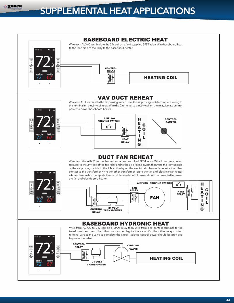
SUPPLEMENTAL HEAT APPLICATIONS
BASEBOARD ELECTRIC HEAT
BASEBOARD HYDRONIC HEAT
DUCT FAN REHEAT
VAV DUCT REHEAT
CONTROL RELAY
HEATING COIL
AIRFLOW
HEAT RELAY
PROVING SWITCHCONTROLDAMPER
HEATING
COIL
AIRFLOW PROVING SWITCH
RELAY
24 VOLT
FAN
TRANSFORMER
RELAYHEAT
CONTROL RELAY
HEATING
COIL
FAN
24 VOLT TRANSFORMER
CONTROL RELAY HYDRONIC
VALVE
HEATING COIL
AUXDS
COM
DS
TR1TR2
MCRORC
GND
AB �� �
�
� � � � �� � � � � � �� �
� � � � � �
AUXDS
COM
DS
TR1TR2
MCRORC
GND
AB �� �
�
� � � � �� � � � � � �� �
� � � � � �
AUXDS
COM
DS
TR1TR2
MCRORC
GND
AB �� �
�
� � � � �� � � � � � �� �
� � � � � �
AUXDS
COM
DS
TR1TR2
MCRORC
GND
AB �� �
�
� � � � �� � � � � � �� �
� � � � � �
Wire one AUX terminal to the air proving switch from the air proving switch complete wiring to the terminal on the 24v coil relay. Wire the C terminal to the 24v coil on the relay. Isolate control power to power baseboard heater.
Wire from AUX/C terminals to the 24v coil on a field supplied SPDT relay. Wire baseboard heat to the load side of the relay to the baseboard heater.
Wire from the AUX/C to the 24v coil on a field supplied SPDT relay. Wire from one contact terminal to the 24v coil of the fan relay and to the air proving switch then wire the leaving side of the air proving switch to the 24v coil relay on the electric stripheater. Now wire the other contact to the transformer. Wire the other transformer leg to the fan and electric strip heater 24v coil terminals to complete the circuit. Isolated control power should be provided to power the fan and electric strip heater.
Wire from AUX/C to 24v coil on a SPDT relay then wire from one contact terminal to the transformer and from the other transformer leg to the valve. On the other relay contact terminal wire to the valve to complete the circuit. Isolated control power should be provided to power the valve.
� � � � �
� � � � �
� � � � �
� � � � �
44
� � �� � �� �
� � �� � �� �
� � �� � �� �
� � �� � �� �

DIRECT WIRELESS CONNECTION
45
The GEN X can be configured to connect directly wirelessly between a mobile device for the purpose of com-munication and configuration. A connection between mobile devices is done with a static IP address. The following steps below outline this procedure.
Wireless connection for Android devices
1. Ensure that an Ethernet cable is NOT plugged into the GEN X (when a cable is plugged in the WiFi capability is automatically disabled).
2. Download the GEN X App from the Google Play store and install it on your mobile device.
3. On your mobile device open your Wi-Fi settings and scan for networks.
4. If the GEN X is powered on and within range “GENX” should appear in the list of the networks available to connect to.
5. Tap on “GENX” in the list of networks, your mobile device will attempt to connect to the GEN X and a popup list should appear. On the pop- up list select “Show advanced options”. If the popup list does not ap- pear press and hold “GENX” until a popup list does appear, then tap “Modify network” and then select “Show advanced options”.
6. Under “IP settings” change “DHCP” to “Static”, under the IP address field type in 10.10.10.10, under the Gateway field type in 10.10.10.1 under the Subnet field (if present) type in 255.255.255.0 and then save the settings or tap “Connect”.
7. The word “Connected” should appear under “GENX” in the network list of your mobile device.
8. Open the GEN X mobile app, tap “Yes” for local access, tap “SCAN LAN FOR GEN X” and once the scan is complete select the GEN X from the drop down list at the top of the app.
9. Your mobile device is now connected to the GEN X via wireless connection. Configuration changes can now be made to the GEN X. If the GEN X is to be connected to an existing wireless network please call Zonex tech support to help with this set up. Please note that the GEN X Wi-Fi range is approx 50 feet.

46
Wireless connection for Apple devices
1. Ensure that an Ethernet cable is NOT plugged into the GEN X (when a cable is plugged in the WiFi capability is automatically disabled).
2. Download the GEN X App from the Apple App Store and install it on your mobile device.
3. On your mobile device tap on Settings and then tap on Wi-Fi. Ensure Wi-Fi is turned on.
4. If the GEN X is powered on and within range “GENX” should appear under CHOOSE A NETWORK. Tap on GENX once, GENX will then be automatically moved under Wi-Fi, tap GENX one more time.
5. Under IPV4 ADDRESS tap Configure IP. On the next menu tap Manual. A menu will appear just below labeled MANUAL IP.
6. In the IP address field type in 10.10.10.10, in the Subnet Mask field type in 255.255.255.0 and in the Router field type in 10.10.10.1, and then tap Save.
7. Once connected the mobile device should have a check mark next to GENX indicating a connection.
8. Open the GEN X mobile app for local access, tap “SKIP ACCOUNT LOGIN -- LOCAL CONNECTION ONLY” and once the scan is complete select the GEN X from the drop down list at the top of the app.
9. Your mobile device is now connected to the GEN X via wireless connection. Configuration changes can now be made to the GEN X. If the GEN X is to be connected to an existing wireless network please call Zonex tech support to help with this set up. Please note that the GEN X Wi-Fi range is less the 50 feet.
DIRECT WIRELESS CONNECTION

An account needs to be created to access the GEN X system over the internet. Follow the steps below on how to create an account.
Open the Zonex mobile app and go to the log in screen.
Select - CREATE NEW ACCOUNT
Enter your information to sign up
USERNAME (case senstive)
PASSWORD (case senstive)
GIVEN NAME
EMAIL ADDRESS
PHONE NUMBER
A confirmation code will be emailed to confirm the new account creation
ENTER THE CONFIRMATION CODE AND CONFIRM
NOTE: If you do not receive the confirmation code email, check the spam folder.
Once this step is completed you will need to contact Zonex tech support at 800-228-2966 to confirm and complete the account set up.
47
ACCOUNT SET UP

System Configuration Menus
GEN X MOBILE APPThe mobile App commicates with the GEN X controller, via the Wi-Fi network and initiates control decisions for the system. Through the GEN X mobile app you can coordinate global or individual schedules for the system, lock thermostats individually and provide a user interface to make adjustments and establish master temperature settings individually or globally for the system. This user interface provides diagnostic functions to streamline system troubleshooting along with air balance shortcuts, password protection and many additional functions.
You will find outlined below the 25 unique functions that the GEN X offers:
System feature changes are configured through the GEN X Mobile App for all zone stats and the GEN X System controller, along with additional RTU or Split systems controlled by their RM board.
MENU FEATURES:
01 SET SCHEDULE / VACATION SCHEDULE02 LOCK03 TURN THERMOSTATS ON/OFF04 SYSTEM DIAGNOSTIC05 SET HIGH / LOW LIMITS06 SET SECOND STAGE DELAY TIME07 SET OVERRIDE HOURS08 SET PRIORITY MODE09 FAN MODE10 UNIT TYPE11 SET MAVRICK MODE12 ENABLE WARM UP MODE13 TEMPERATURE FORMAT F° / C°
14 ENABLE AIR BALANCE MODE15 SET STAT ZONE NAMES16 CHANGE GEN X / RM UNIT NAME17 CONFIGURE NUMBER OF THERMOSTATS18 CONFIGURE NUMBER OF RM’S ATTACHED TO SYSTEM19 ASSIGN RM ID20 CONFIGURE NUMBER OF RLY-X ATTACHED TO SYSTEM21 ASSIGN RLY-X ID22 SEE ZONE OVERVIEW23 CHANGE ALARM SETTINGS24 CHANGE ADR SETTINGS
48

01 SCHEDULE / VACATION
Tap Set Schedule or Tap onTap Change Daily Schedule formatChoose your format 5-1-1, 24/7 or Daily ScheduleTap Set Daily ScheduleTap M-F ALLChoose Set Occupied Time or Set UnoccupiedSet Occupied Start Time, Press OkSet Occupied End Time, Press Ok
Tap Sat or Sun ALLChoose Set Occupied Time or Set UnoccupiedSet Occupied Start Time, Press OkSet Occupied End Time, Press Ok
SETTING 2ND DAILY SCHEDULE:Tap Set 2nd Daily ScheduleTap M-F ALLChoose Set Occupied Time or Set UnoccupiedSet Occupied Start Time, Press OkSet Occupied End Time, Press Ok
Tap Sat or Sun ALLChoose Set Occupied Time or Set UnoccupiedSet Occupied Start Time, Press OkSet Occupied End Time, Press Ok
VACATION SCHEDULETap Set ScheduleChoose Set Vacation SchedulePress Add VacationTap a Date on the Calendar to Start Vacation and another to End Vacation, Press OkTap Enable VacationsChoose Individual zones or All Zones to follow vacation schedule
TO NAME A VACATION SCHEDULETap the Vacation schedule that you want to nameTap Change name and enter the new name, Press Ok
TO DELETE OR EDIT A VACATION SCHEDULETap the current Vacation Schedule you want to Delete or EditTap Delete or Edit
GEN X MOBILE APP
49

02 LOCK THERMOSTATS
03 TURN THERMOSTATON / OFF
Tap Turn Thermostat On/Off
Select the zone or zones you want to turn Off or On
Confirms zone thermostat is locked.
The thermostat On and Off func�on will allow you to turn individualthermostats On and Off.
To turn OFF the thermostat uncheck the box.
Note: Off is displayed on the thermostat.
GEN X MOBILE APP
Thermostats can be locked independently or globally through your Mobile device, when a thermostat is locked the end user will have limited opera�on (+/- 2°) or no variance (0°) of the theromstat from hea�ng or cooling set points.
Tap Lock ThermostatsSelect Zone Stat or All Zones and choose +/- 2° or 0° lock.
50

05 HIGH/LOW LIMIT
For system protec�on the GEN X has High and Low limit set point built into the Mobile Device configura�ons. Factory defaults for Gas/Electric opera�ons are High Limit of 145° F and Low Limit of 45 °F, for Heat Pump opera�ons factory defaults are High Limit 115° F and Low Limit of 45° F. These can be field configured as required.
Tap Set High/Low Limit Tap Set High Limit, Confirm or Change High Limit
(Range 100° F - 160° F) Select OK when done Tap Set High/Low Limit Tap Set Low Limit, Confirm or Change Low Limit
(Range 40 ° F - 50 ° F) Tap OK when done
04 SYSTEM DIAGNOSTIC
Tap System Diagnos�c or access from Extendedfeature menu.
Scroll Down to view Ac�ve Zones and unit condi�ons.
Tapping on a zone thermostat, (under ThermostatStatus) will allow you to adjust the zone set point.
Troubleshoo�ng Note: System Diagnos�c is a greattool to use to confirm communica�ons with thermostatsand detect communica�on errors or wiring errors in thesystem.
GEN X MOBILE APP
Allow the user to review the current condi�ons for the GEN X systems. Number of Ac�ve thermostats in the system, how many are communi-ca�ng, thermostats that are off, Unit status, Leaving Air Temperature, Return Air Temerature and Outside Air Temperature all from your mobile device.
51

07 OVERRIDE HOURS
Tap Set Override Hours Choose 2-8 hours for override opera�on, Tap OK
06 SECOND STAGE DELAY
Tap Set Second Stage Delay Se�ngs Enable Second Stage Delay Tap Set Second Stage Delay Time Choose 3-30 minutes, Tap OK
This is a global func�on, all thermostats on thisunit will operate with the override �me selected.
The GEN X controller can be configured for TIME/TEMP or TIMEONLY second stage opera�on. TIME/TEMP strategy uses both run�me and leaving air temperature to determine when to ini�ate second stage heat or cool. TIME ONLY strategy uses run �me to stagesecond stage heat/cool opera�on. Factory default is TIME/TEMP, therun �me is preset to 3 minutes; however this can be reset up to 30 minutes.
Time / Temp Configuration
Time only ConfigurationTap Set Second Stage Delay Se�ngsTap Set Second Stage Delay TimeChoose 3-30 minutes, Tap OK Disable Second Stage Delay by tapping the checked box.
GEN X MOBILE APP
52
Select the number of hours to ini�ate override opera�on. Select 2-8 hours in the setback mode. Tap once on the thermostat to ini�ate override opera�on. The “override” can be tapped again to terminate override opera�on.
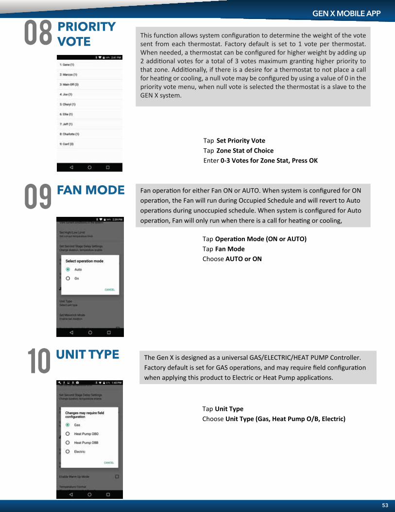
08 PRIORITY VOTE
10 UNIT TYPE
Tap Set Priority Vote Tap Zone Stat of Choice Enter 0-3 Votes for Zone Stat, Press OK
The Gen X is designed as a universal GAS/ELECTRIC/HEAT PUMP Controller. Factory default is set for GAS opera�ons, and may require field configura�on when applying this product to Electric or Heat Pump applica�ons.
Tap Unit Type Choose Unit Type (Gas, Heat Pump O/B, Electric)
09 FAN MODE Fan opera�on for either Fan ON or AUTO. When system is configured for ON opera�on, the Fan will run during Occupied Schedule and will revert to Auto opera�ons during unoccupied schedule. When system is configured for Auto opera�on, Fan will only run when there is a call for hea�ng or cooling,
Tap Opera�on Mode (ON or AUTO) Tap Fan Mode Choose AUTO or ON
GEN X MOBILE APP
This func�on allows system configura�on to determine the weight of the vote sent from each thermostat. Factory default is set to 1 vote per thermostat. When needed, a thermostat can be configured for higher weight by adding up 2 addi�onal votes for a total of 3 votes maximum gran�ng higher priority to that zone. Addi�onally, if there is a desire for a thermostat to not place a call for hea�ng or cooling, a null vote may be configured by using a value of 0 in the priority vote menu, when null vote is selected the thermostat is a slave to the GEN X system.
53

Tap Set Maverick Mode Enable Maverick Mode ( Enabled when box is checked)Choose 3-30 minutes, Press OK
12 ENABLEWARM UP MODE
11MASTER CONTROL
SET MAVERICK
In cold climates a MORNING WARM UP sequence will assist in prehea�ng the building prior to occupancy. The GEN X system provides a strategy for morning warm up based on a sophis�cated algorithm built into the system controller. When enabled, the system will switch from Unoccupied to Occupied two hours prior to system start �me and run hea�ng for 20 minutes to evaluate �me needed to raise building temperature, a�er 20 minutes system will return to Unoccupied mode. Using the informa�on gathered from the 20 minute warm up evalua�on, thermostats will reset individual occupied start �mes to provide morning warm up for each zone in the building.
Enable Warm up Mode (Enabled when box is checked)
GEN X MOBILE APP
Maverick opera�ons allow the system to recognize an outlier call in the system. When most zones in asystem are calling for heat and 1 zone is calling for cooling, the system will ini�ate a MAVERICK CALLprotocol by star�ng a �me clock. Logic in the controller will provide a �me period for first calls to sa�sfy,and then run a purge cycle and energize the maverick call. Maverick call will remain on un�l zone sa�sfied,then run purge and return to majority opera�ons.
54

13 TEMPERATURE FORMAT
GEN X may be configured for F° or C° opera�ons.
Tap Temperature Format Choose F° or C°
AIR BALANCE MODE14
During the start up and commissioning of the system, an air balance may be required. Enable the air balance mode to Start, this will drive all dampers to the open posi�on, energize the fan and lock out compressor or heat func�on. When air balance is complete, Tap the Enable Air Balance mode to STOP air balance mode and place the system back to normal opera�on.
Enable Air Balance Mode (Enabled when box is checked)
15 SET STAT ZONE NAMES
This allows you to give each zone a specific name.
Tap Set Stat Zone Names Tap Zone stat that you want to name Enter name of zone, Press OK Repeat for all addi�onal zones that need to be named
GEN X MOBILE APP
55

18 CONFIGURE NUMBEROF RM’S ATTACHEDTO SYSTEM
17 CONFIGURE NUMBEROF THERMOSTATS
Tap Number of Thermostats
16 CHANGE GEN X / RMUNIT NAMES This allows you to give the GEN X and GEN X RM’s a specific name.
Tap Change GEN X / RM Unit Names Tap Unit you want to name Enter name for that unit, Press OK Repeat for all addi�onal units that need to be named
Tap Configure Number of RM’s A�ached to Systemand enter the number of RM’s a�ached to the system.Note: Each RM can support up to 20 thermostats or zones
Enter how many zones in this system 1-20, Press OK
GEN X MOBILE APP
Installer must set the number of thermostats in the system. This reduces the need for the GEN X controller to poll and review each zone’s needs. Installer can set the number of thermostats from 1-20.
Configuring the number of RM’s a�ached to system allows the GEN X to know how many RM’s it will be communica�ng with. It also needs to know how many RM’s will be in the system to sync properly.
56
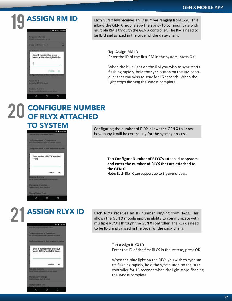
19 ASSIGN RM ID
Tap Assign RM IDEnter the ID of the first RM in the system, press OK
When the blue light on the RM you wish to sync starts flashing rapidly, hold the sync bu�on on the RM contr-oller that you wish to sync for 15 seconds. When the light stops flashing the sync is complete.
GEN X MOBILE APP
Each GEN X RM receives an ID number ranging from 1-20. This allows the GEN X mobile app the ability to communicate with mul�ple RM’s through the GEN X controller. The RM’s need to be ID'd and synced in the order of the daisy chain.
21 ASSIGN RLYX ID
Tap Assign RLYX IDEnter the ID of the first RLYX in the system, press OK
When the blue light on the RLYX you wish to sync sta-rts flashing rapidly, hold the sync bu�on on the RLYX controller for 15 seconds when the light stops flashing the sync is complete.
Each RLYX receives an ID number ranging from 1-20. This allows the GEN X mobile app the ability to communicate with mul�ple RLYX’s through the GEN X controller. The RLYX’s need to be ID'd and synced in the order of the daisy chain.
20 CONFIGURE NUMBEROF RLYX ATTACHEDTO SYSTEM
Configuring the number of RLYX allows the GEN X to know how many it will be controlling for the syncing process
Tap Configure Number of RLYX’s a�ached to systemand enter the number of RLYX that are a�ached to the GEN X.Note: Each RLY-X can support up to 5 generic loads.
57

22 SEE ZONE OVERVIEW
Select Zone Overview to see all zone set pointsand current room temperatures
Zone overview will let you review all the zones, current room temperatures, ac�ve cooling calls in blue, ac�ve hea�ng calls in red along with Occupied and Unoccupied set points.
GEN X MOBILE APP
58
23 ALARM SETTINGS
Select Change Alarm Se�ngs Enable zone out of range alarm
Select Set �me out of range for alarm (5-90 minutes)Enter the �me to wait before alarming; Press Ok
Select Set temperature out of range for alarm (3-9°)Enter temperature threshold for alarming; Press Ok
Select Alarm Subscrip�on Se�ngs to add/remove textand email alarm subscrip�ons.
Select Sign up for alarm no�fica�ons email or textand enter the email addresses or phone #’s of theindividuals that want to receive the alarm no�fica�ons.
You will receive a Subscrip�on Confirma�on email,to ac�vate the alarming you will need to confirm the subscrip�on.
To Unsubscribe from Alarms, en�re the email addressor phone # in the Unsubscribe from alarms.
* For alarming to func�on, account set up is required.
Once enabled this allows email/text no�fica�ons of faults in the system such as low ba�ery, temerature out of range.

24 CHANGE ADRSETTINGS
Tap Change ADR Se�ngsSelect the zone or zones you want to enable
To enable the thermostat for ADR
When the 3rd party device receives an ADR signal from the u�lity service provider its contacts close, the GEN X & RM’s set back their thermostats 4° for both the hea�ng & cooling modes and lock the thermostat set points so they cannot be adjusted at the thermostat during the ADR event. Once the ADR event has concluded the thermostats unlock and return to their original set points.
GEN X MOBILE APP
59

GEN X MOBILE APP EXTENDED MENU OPTIONS
60
The Extended Menu Options will allow access to additional control systems tied to the GEN X controller or account, check the system diagnostic, view contractors information and log out or exit the app.
System Diagnostic - Gives an overview of the system you are currently connected to including number of Thermostats the system is configured for, Leaving, Return & Outside air temps, System Status (Heat, Cool or Vent operation), number of Heat and Cool calls and Thermostat Status.
Log Out of Account – Will log you out of your account and takes you back to the option screen for logging in to the system over the internet or accessing a system on the same local network that your mobile device is also connected to. Change RM/GEN X (Same System) – Allows you to switch between a GEN X and RM’s on the same system you are currently connected to. This option can be used for over the internet or local network connections.
Change RM/GEN X (Separate System) – Allows you to connect to any of the GEN X systems that are associ-ated with your user account. This option is used for over the internet connections only.
Exit App – Closes the GEN X app.

47
GEN X WEB-PORTAL
The GEN X controller can be accessed from any web browser. Accesing the GEN X over the internet requires a user name and password that is set up through the Zonex moblie app and confirmed by Zonex tech support.
If you need help setting up an account call Zonex tech support at 800-228-2966.
To access the GEN X go to: www.genxcontrol.com
Enter the user name and password: Click Login
GEN X WEB-PORTAL LOGIN - END USER INTERFACE
61
END USER INTERFACE OVERVIEWYou can review and perform the following:
-Review all zones on a system by system basis-Change occupied and unoccupied thermostat setpoints-Lock/unlock thermostats-Review the system status, leaving and return air temperatures-Review priority votes on zone thermostats-Review and change zone schedules and vacation days-Review and change zone names-Set temperature format

ZONE OVERVIEW
62
Once you have logged into the end user interface you will see all the zone thermostats associated with the GEN X controller.
To see other zoned roof top units or split systems. Click in the left hand column, a drop down will appear. Click on the RM controller that you wish to view.
ZONE OVERVIEW
Note: If the web-portal doesn’t seem to load right, delete the cash and cookies in the web browser and reload the web-portal.

CHANGING TEMPERATURES
CHANGING ZONE THERMOSTAT TEMPERATURES To change temperatures on a zone thermostat. Click the zone you wish to change the temperature on.
To change either the Cool set point (Blue Dot) or Heat set point (Red Dot) slide the corresponding dot to the left to lower the temperature and to the right to raise the temperature. After making temperature changes click on the X in the upper right corner of the pop up box to exit this screen. Changes will be transmitted to thermo-stats remotely.
Both Occupied and Unoccupied set points can be changed at this screen.
Note: The system is designed to maintain a 2° dead band between the heating and cooling set points.
63

DIAGNOSTICS SCREEN
64
DIAGNOSTICS SCREEN The diagnostic screen allows you to view the leaving, return, and outside air temperatures and the current status of the system.
Under the Priority Votes column you can view the number of votes assigned to a thermostat as well as the mode of operation the thermostat is calling for (Cool, Heat, or Off/No Call).
The buttons under the Locked/Unlocked column are used to change thermostats so they can be LOCKED with 0° variance, PARTIAL LOCK +/- 2° or UNLOCKED. If you wish to lock or unlock all zone thermostats click on Unlock All / Lock All in the bottom right corner below the last zone status.
The Status column indicates the current status of communication between the thermostat and GEN X control-ler.
If you have standalone thermostats (SATouchX) connected to the GEN X / GEN X RM controllers, the humidity, leaving and return air temperatures are displayed at the bottom of the diagnostic screen.
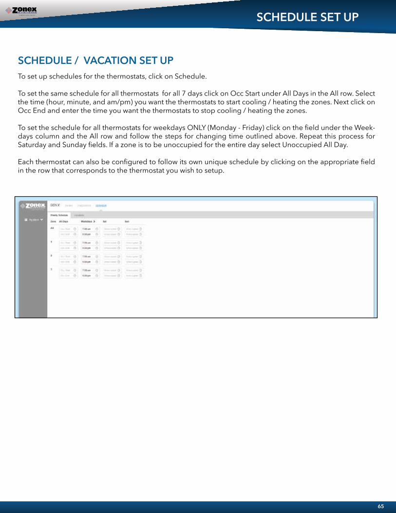
SCHEDULE SET UP
SCHEDULE / VACATION SET UP To set up schedules for the thermostats, click on Schedule.
To set the same schedule for all thermostats for all 7 days click on Occ Start under All Days in the All row. Select the time (hour, minute, and am/pm) you want the thermostats to start cooling / heating the zones. Next click on Occ End and enter the time you want the thermostats to stop cooling / heating the zones.
To set the schedule for all thermostats for weekdays ONLY (Monday - Friday) click on the field under the Week-days column and the All row and follow the steps for changing time outlined above. Repeat this process for Saturday and Sunday fields. If a zone is to be unoccupied for the entire day select Unoccupied All Day.
Each thermostat can also be configured to follow its own unique schedule by clicking on the appropriate field in the row that corresponds to the thermostat you wish to setup.
65
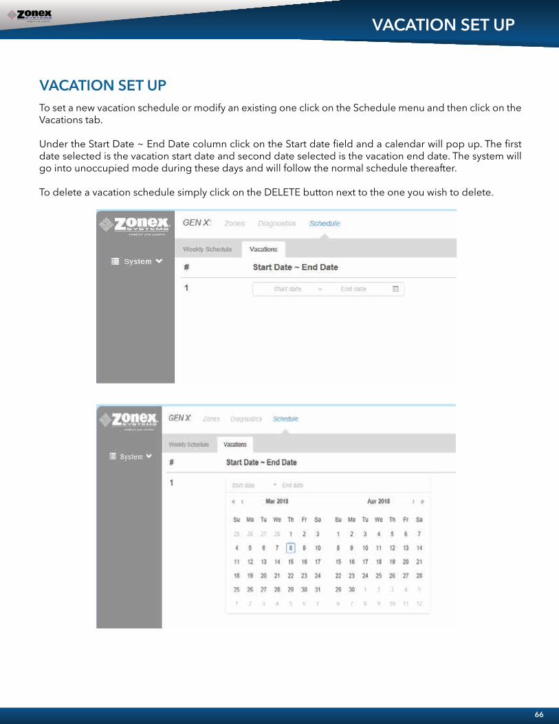
VACATION SET UP
VACATION SET UP To set a new vacation schedule or modify an existing one click on the Schedule menu and then click on the Vacations tab.
Under the Start Date ~ End Date column click on the Start date field and a calendar will pop up. The first date selected is the vacation start date and second date selected is the vacation end date. The system will go into unoccupied mode during these days and will follow the normal schedule thereafter.
To delete a vacation schedule simply click on the DELETE button next to the one you wish to delete.
66

TEMPERATURE FORMAT AND ZONE NAMES
The options under the Settings menu will allow changes to the temperature format, system name and zone names.
To change the temperature scale click on the button below Temp. Display Format and the switch will move to the left for Fahrenheit and to the right for Celsius.
To change either the System Name or Zone Names move the pointer over the name to be changed, click on Edit, change the field to the desired name and click on Save.
CHANGING TEMPERATURE FORMAT AND ZONE NAMES
67
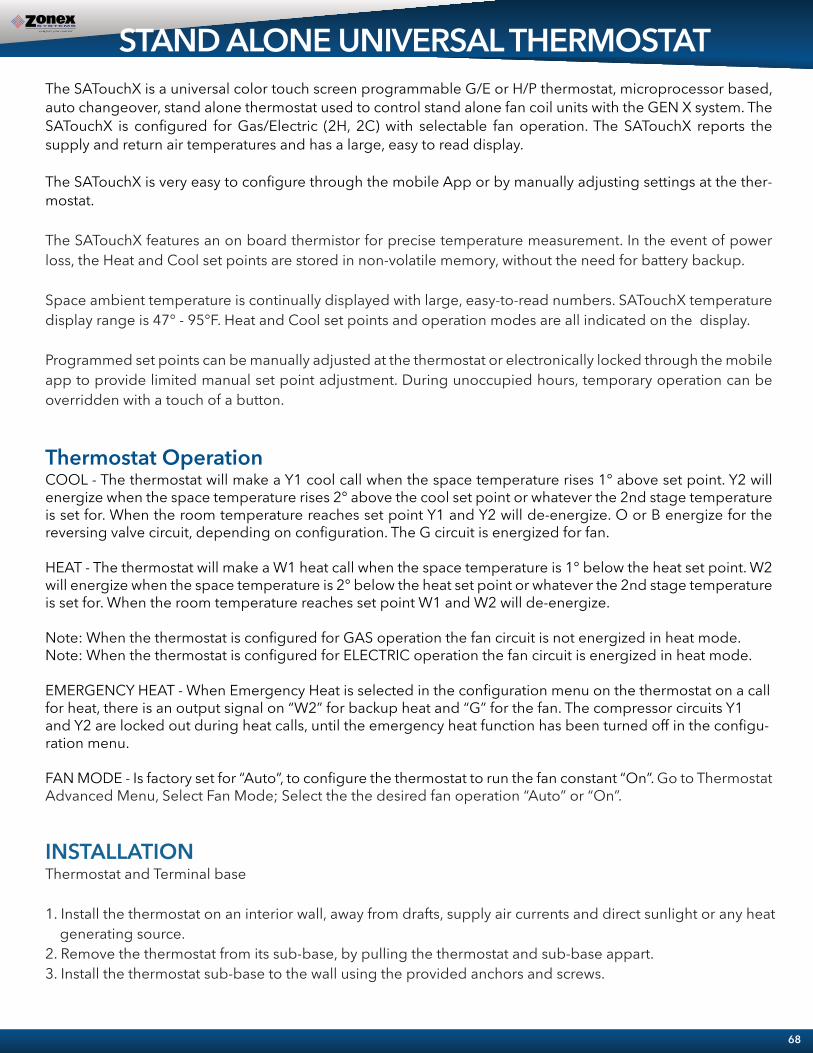
STAND ALONE UNIVERSAL THERMOSTATThe SATouchX is a universal color touch screen programmable G/E or H/P thermostat, microprocessor based, auto changeover, stand alone thermostat used to control stand alone fan coil units with the GEN X system. The SATouchX is configured for Gas/Electric (2H, 2C) with selectable fan operation. The SATouchX reports the supply and return air temperatures and has a large, easy to read display.
The SATouchX is very easy to configure through the mobile App or by manually adjusting settings at the ther-mostat.
The SATouchX features an on board thermistor for precise temperature measurement. In the event of power loss, the Heat and Cool set points are stored in non-volatile memory, without the need for battery backup.
Space ambient temperature is continually displayed with large, easy-to-read numbers. SATouchX temperature display range is 47° - 95°F. Heat and Cool set points and operation modes are all indicated on the display.
Programmed set points can be manually adjusted at the thermostat or electronically locked through the mobile app to provide limited manual set point adjustment. During unoccupied hours, temporary operation can be overridden with a touch of a button.
Thermostat OperationCOOL - The thermostat will make a Y1 cool call when the space temperature rises 1° above set point. Y2 will energize when the space temperature rises 2° above the cool set point or whatever the 2nd stage temperature is set for. When the room temperature reaches set point Y1 and Y2 will de-energize. O or B energize for the reversing valve circuit, depending on configuration. The G circuit is energized for fan.
HEAT - The thermostat will make a W1 heat call when the space temperature is 1° below the heat set point. W2 will energize when the space temperature is 2° below the heat set point or whatever the 2nd stage temperature is set for. When the room temperature reaches set point W1 and W2 will de-energize.
Note: When the thermostat is configured for GAS operation the fan circuit is not energized in heat mode. Note: When the thermostat is configured for ELECTRIC operation the fan circuit is energized in heat mode.
EMERGENCY HEAT - When Emergency Heat is selected in the configuration menu on the thermostat on a call for heat, there is an output signal on “W2” for backup heat and “G” for the fan. The compressor circuits Y1 and Y2 are locked out during heat calls, until the emergency heat function has been turned off in the configu-ration menu.
FAN MODE - Is factory set for “Auto”, to configure the thermostat to run the fan constant “On”. Go to Thermostat Advanced Menu, Select Fan Mode; Select the the desired fan operation “Auto” or “On”.
INSTALLATIONThermostat and Terminal base
1. Install the thermostat on an interior wall, away from drafts, supply air currents and direct sunlight or any heat generating source.2. Remove the thermostat from its sub-base, by pulling the thermostat and sub-base appart.3. Install the thermostat sub-base to the wall using the provided anchors and screws.
68
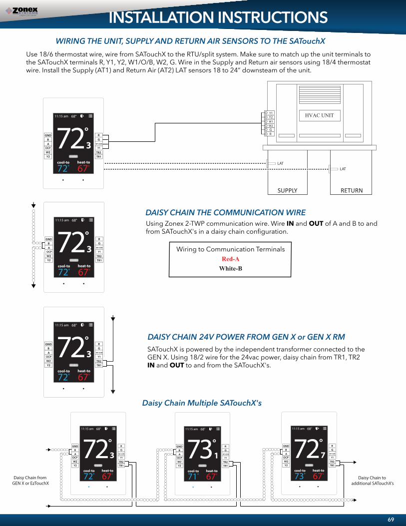
69
INSTALLATION INSTRUCTIONS
Wiring to Communication TerminalsRed-A
White-B
Using Zonex 2-TWP communication wire. Wire IN and OUT of A and B to and from SATouchX's in a daisy chain configuration.
SATouchX is powered by the independent transformer connected to the GEN X. Using 18/2 wire for the 24vac power, daisy chain from TR1, TR2 IN and OUT to and from the SATouchX's.
Daisy Chain Multiple SATouchX's
WIRING THE UNIT, SUPPLY AND RETURN AIR SENSORS TO THE SATouchX
DAISY CHAIN THE COMMUNICATION WIRE
DAISY CHAIN 24V POWER FROM GEN X or GEN X RM
Use 18/6 thermostat wire, wire from SATouchX to the RTU/split system. Make sure to match up the unit terminals to the SATouchX terminals R, Y1, Y2, W1/O/B, W2, G. Wire in the Supply and Return air sensors using 18/4 thermostat wire. Install the Supply (AT1) and Return Air (AT2) LAT sensors 18 to 24” downsteam of the unit.
Y2W2
GND
AB �� �
�
� � � � �� � � � � � �� �
� � � � � �
� � �� � �� � � � �
� � � � �
W1-O/B
G
Y1
R
TR1TR2
Y2W2
GND
AB �� �
�
� � � � �� � � � � � �� �
� � � � � �
� � �� � �� � � � �
� � � � �
OCP
OCP
W1-O/B
G
Y1
R
TR1TR2
�� ��
� � � � �� � � � � � �� �
� � � � � �
� � �� � �� � � � �
� � � � �
OCP
Y2W2
GND
AB
W1-O/B
G
Y1
R
TR1TR2
�� ��
� � � � �� � � � � � �� �
� � � � � �
� � �� � �� � � � �
� � � � �
OCP
Y2W2
GND
AB �� �
�
� � � � �� � � � � � �� �
� � � � � �
� � �� � �� � � � �
� � � � �
OCP
Y2W2
GND
AB �� �
�
� � � � �� � � � � � �� �
� � � � � �
� � �� � �� � � � �
� � � � �
OCP
Y2W2
GND
AB
OCP OCP OCPW1-O/B
G
Y1
R
TR1TR2
W1-O/B
G
Y1
R
TR1TR2
W1-O/B
G
Y1
R
TR1TR2
Daisy Chain from GEN X or EzTouchX
Daisy Chain to additional SATouchX’s
OCP
HVAC UNIT
SUPPLY RETURN
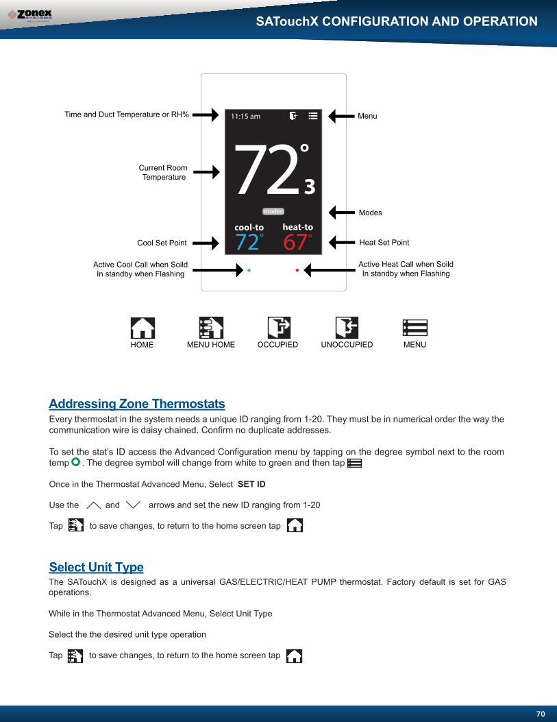
SATouchX CONFIGURATION AND OPERATION
70
Current Room Temperature
Modes
Cool Set Point
Menu Time and Duct Temperature or RH%
Heat Set Point
Addressing Zone ThermostatsEvery thermostat in the system needs a unique ID ranging from 1-20. They must be in numerical order the way the communication wire is daisy chained. Confirm no duplicate addresses.
To set the stat’s ID access the Advanced Configuration menu by tapping on the degree symbol next to the room temp . The degree symbol will change from white to green and then tap
Once in the Thermostat Advanced Menu, Select SET ID
Use the and arrows and set the new ID ranging from 1-20
Tap to save changes, to return to the home screen tap
Select Unit TypeThe SATouchX is designed as a universal GAS/ELECTRIC/HEAT PUMP thermostat. Factory default is set for GAS operations.
While in the Thermostat Advanced Menu, Select Unit Type
Select the the desired unit type operation
Tap to save changes, to return to the home screen tap
�� ��
� � � � �� � � � � � �� �
� � � � � �
� � � � �
Active Heat Call when SoildIn standby when Flashing
MENU OCCUPIED UNOCCUPIEDMENU HOMEHOME
Active Cool Call when SoildIn standby when Flashing
� � �� � �� �

71
Adjusting Set PointsThe Heat or Cool set points are displayed at the bottom of the screen. To adjust the set points, tap on the heat-to or cool-to temperatures; the set points will be displayed on the screen.
Use the and arrows over the flame/snowflake icons to set the desired heat and cool set points.
Tap to save changes
Changing ModeThe thermostats are auto changeover, but specific modes may be selected. Heat/Cool mode is the default.
System Heat/Cool - Tap on , select “Heat/Cool”. Tap to save changes System Heat Only - Tap on , select “Heat Only”. Tap to save changes
System Cool Only - Tap on , select “Cool Only”. Tap to save changes
System Off - Tap on , select “Off”. Tap to save changes
Override OperationWhen the thermostat displays the unoccupied icon a 2-8 hour temporary override may be initiated by tapping the “Override” will appear. When additional override time is required, tap the unoccupied icon again.
� � � � �
� � � � �
� � � � �
� � � � �
SATouchX CONFIGURATION AND OPERATION
Display Temperature CalibrationThermostats are calibrated at the factory and should require no further adjustment. However, the display space tempera-ture may be field calibrated by the following procedure:
To access the Thermostat Configuration Menu: Tap
While in Thermostat Configuration Menu, Select Calibrate Display
Use the and arrows to calibrate the thermostat display to a external temperature probe temperature reading.
Tap to save changes, to return to the home screen tap

72
�� ��
� � � � �� � � � � � �� �
� � � � � �
While in the Thermostat Configuration Menu, Select Set Temperature
Use the and arrows over the flame/snowflake icons to set the desired heat and cool set points.
Tap to save changes, to return to the home screen tap Shortcut note: Tap on cool to/heat to to adjust setpoints.
While in the Thermostat Configuration Menu, Select Override/Unoccupied
Tap “override” to place the thermostat into a override mode.
Tap to save changes, to return to the home screen tap
Shortcut note: Tap on to place the thermostat into override mode
THERMOSTAT CONFIGURATION MENUTo access the Thermostat Configuration Menu: Tap
The THERMOSTAT CONFIGURATION MENU allows you to:Override/Unoccupied Select Unoccupied Light Current Schedule Calibrate Display Set Temperature Mode Time & DateSelect Occupied Light Set Display Accuracy Temperature F/C
OVERRIDE/UNOCCUPIEDWhen a thermostat displays “unoccupied mode ”, a 2-8 hour temporary override maybe initiated.
When in the “Set Temperature” screen you can adjust the heat/cool set points to their desired temperature settings.
SET TEMPERATURE
SATouchX CONFIGURATION MENU
� � �� � �� �
� � �� � �� �
� � �� � �� � � � �� � �� �

73
SATouchX CONFIGURATION MENU
MODE
SELECT OCCUPIED LIGHT
Thermostat mode allows the thermostat to be set to heat/cool, cool only, heat only of off operation.
While in Thermostat Configuration Menu, Select Occupied Light
Use the and arrows to select the desired brightness.
Tap to save changes, to return to the home screen tap
Note: If “off” is selected, just touch stat to wake it up.
While in the Thermostat Configuration Menu, Select Mode
Select the desired operation mode
Tap to save changes, to return to the home screen tap
Shortcut note: Tap on the home screen to access the mode selection screen
� � � � �
� � �� � �� �
� � �� � �� �
The brightness of the thermostat during occupied mode is adjustable from 100% down to off .
SELECT UNOCCUPIED LIGHT
While in Thermostat Configuration Menu, Select Unoccupied Light
Use the and arrows to select the desired brightness.
Tap to save changes, to return to the home screen tap
Note: If “off” is selected, just touch stat to wake it up.
The brightness of the thermostat during unoccupied mode is adjustable from 100% down to off .
� � �� � �� �
select occupied light
select unoccupied light

74
SATouchX CONFIGURATION MENU
Display accuracy allows the thermostat to display the room temperature in 1/10° or 1°.
SET DISPLAY ACCURACY
While in the Thermostat Configuration Menu, Select Set Display Accuracy
Select the desired display accuracy
Tap to save changes, to return to the home screen tap
� � �� � �� �
TIME & DATEView the current time and day, given by the Gen X system
While in the Thermostat Configuration Menu, Select Time & Date
View the current time and date on the Gen X system
Tap to go back to the menu, to return to the home screen tap
� � �� � �� � � � �
CURRENT SCHEDULEView the current thermostat schedule, given by the Gen X system
While in the Thermostat Configuration Menu, Select Current Schedule
This allows you to view the schedule for that zone. Changes to the schedule are done through the Gen X app.
Tap to go back to the menu, to return to the home screen tap
� � �� � �� � � � �
-
� � �� � �� �
� � �� � �� �
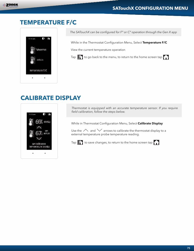
75
TEMPERATURE F/CThe SATouchX can be configured for F° or C° operation through the Gen X app
While in the Thermostat Configuration Menu, Select Temperature F/C
View the current temperature operation
Tap to go back to the menu, to return to the home screen tap
� � �� � �� �
SATouchX CONFIGURATION MENU
CALIBRATE DISPLAYThermostat is equipped with an accurate temperature sensor. If you require field calibration, follow the steps below.
While in Thermostat Configuration Menu, Select Calibrate Display
Use the and arrows to calibrate the thermostat display to a external temperature probe temperature reading.
Tap to save changes, to return to the home screen tap
� � �� � �� �

76
While in the Thermostat Advanced Menu, Select Unit Type
Select the desired unit type operation
Tap to save changes, to return to the home screen tap
While in the Thermostat Advanced Menu, Select SET ID
Use the and arrows to set the new ID ranging from 1-20
Tap to save changes, to return to the home screen tap
Note: (All thermostats recieve a unique ID 001 to 020, maximum of 20 zones per GEN X and GEN X RM controllers.)
THERMOSTAT ADVANCED MENUTo access the Thermostat Advanced Menu: Tap on the degree symbol next to the room temp The degree symbol will change color from white to green and then tap
The THERMOSTAT ADVANCED MENU allows you to:Set ID Select Fan Mode Set Emergancy Heat Temp Source Select Unit Type Set 2nd Stage Temp Diagnostic Menu Type
STAT IDEvery thermostat in the system needs a unique ID. They must be ID’ed in numerical order the way the communication wire is daisy chained. No duplicate addresses.
SELECT UNIT TYPE
01
03
�� ��
� � � � �� � � � � � �� �
� � � � � �
� � � � �
� � �� � �� �
� � �� � �� �
SATouchX ADVANCED MENU
The SATouchX is designed as a universal GAS/ELECTRIC/HEAT PUMP thermostat. Factory default is set for GAS operations.
� � �� � �� �
� ��
� � � � �� � � � � � �� �
� � � � � �
� � �
� � � � �
� � �� � �� �
gaselectricheat pump oboheat pump obb
select unit type
� � �� � �� �
� ��
� � � � �� � � � � � �� �
� � � � � �
� � �
� � � � �
� � �� � �� �
set id 2select unit type gasset 2nd stage temp autoset emergency heat disabled

77
SELECT FAN MODE
SET EMERGANCY HEAT
While in the Thermostat Advanced Menu, Select Set Emergancy Heat
Select “Enabled” for emergancy heat operation.
Tap to save changes, to return to the home screen tap
Note: Only emergancy heat calls will be seen when enabled.
While in the Thermostat Advanced Menu, Select Fan Mode
Select the desired fan operation “Auto” or “On”.
Tap to save changes, to return to the home screen tap
SATouchX ADVANCED MENU
SET 2ND STAGE TEMP
While in the Thermostat Advanced Menu, Select Set 2nd Stage Temp
Use the and arrows to set the 2nd stage temp range from 2°-8°
Tap to save changes, to return to the home screen tap
Fan operation is configured for either Fan ON or AUTO. When system is configured for ON operation, the Fan will run during Occupied schedule and will revert to Auto operations during Unoccupied schedule. When thermostat is configured for Auto operation, Fan will only run when there is a call for heating or cooling.
The SATouchX’s 2nd stage operation is based on room temperature. Staging is adjustable from 2°- 8° from thermostat room temperature.
The SATouchX has an emergency heat function that will lock out the compressor, and energize the Aux heat in the unit.
� � �� � �� � � � �� � �� � �� �
on
auto
select fan mode
� � �� � �� �
set 2nd stage temp
2
� � �� � �� �
enabled
disabled
set emergency heat
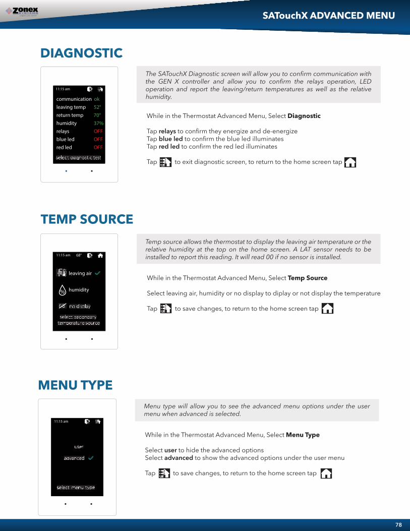
L
W D
78
While in the Thermostat Advanced Menu, Select Menu Type
Select user to hide the advanced optionsSelect advanced to show the advanced options under the user menu
Tap to save changes, to return to the home screen tap
Menu type will allow you to see the advanced menu options under the user menu when advanced is selected.
MENU TYPE
� � �� � �� �
SATouchX ADVANCED MENU
DIAGNOSTIC
While in the Thermostat Advanced Menu, Select Diagnostic
Tap relays to confirm they energize and de-energizeTap blue led to confirm the blue led illuminatesTap red led to confirm the red led illuminates
Tap to exit diagnostic screen, to return to the home screen tap
The SATouchX Diagnostic screen will allow you to confirm communication with the GEN X controller and allow you to confirm the relays operation, LED operation and report the leaving/return temperatures as well as the relative humidity.
� � �� � �� �
communication okleaving temp 52°return temp 70°humidity 37%relays OFFblue led OFFred led OFF
TEMP SOURCETemp source allows the thermostat to display the leaving air temperature or the relative humidity at the top on the home screen. A LAT sensor needs to be installed to report this reading. It will read 00 if no sensor is installed.
While in the Thermostat Advanced Menu, Select Temp Source
Select leaving air, humidity or no display to diplay or not display the temperature
Tap to save changes, to return to the home screen tap
� � �� � �� � � � �
leaving air
humidity%

MEDIUM PRESSURE (STMPD)
Round Medium Pressure Zone Dampers
Round Medium Pressure Damper PART NUMBERS AND SIZES
Note: Round dampers over 18” will be heavy duty style STRD dampers. Part # STRD size
ZONE DAMPERS
Typical Round Capacities
Zonex Systems round (part # STMPD size) medium pressure zone dampers are recommended for systems with a maximum differential static pressure up to 1.75”. This modulating power open/power close damper is manufactured from 20-22 gauge galvanized steel with rolled-in stiffening beads for superior rigidity. Mechanical minimum and maximum set stops are provided and are easily adjustable. The damper is elliptical, which allows the airflow to be tracked linearly. The damper pipe is furnished with one crimped end and one straight end for easy installation. Do not install damper in an inverted position. A hat section supports a reversing 24VAC, 60Hz, 2 VA motor. A magnetic clutch allows for continuous power to the motor and longer motor life. Motor drive time from full open to full close is 90 seconds.
GEN X modulating zone dampers are used in cooling/heating systems to provide room by room zone control. The damper is provided with a factory mounted actuator. Each zone damper is controlled by a zone thermostat. More than one damper can be controlled by one zone thermostat. Use this table to determine which zone dampers to use.
Maximum Differential Pressure refers to the maximum static pressure drop ininches of water column between the input (upstream) of the zone damper and the output (downstream) when the damper is closed.
DAMPER MODEL DIFFERENTIALPRESSURE
MAXIMUMSYSTEM SIZE
MAXIMUMDUCT SIZE
STMPD Round Med. PressureSTMRTD Rect. Med. Pressure
STCD Rect. Heavy DutySTRD Round Heavy Duty
D-FUSER
1.75”1”
1.75”1.75”0.1”
Any Size6.0 TonsAny SizeAny SizeAny Size
18”24”W x 20”H48”W x 48”H
24”10”
PART#STMPD06STMPD08STMPD10STMPD12STMPD14STMPD16STMPD18STRD20STRD22STRD24
SIZE68
1012141618202224
D6”8”
10”12”14”16”18”20”22”24”
L10”10”12”14”16”18”23”24”24”24”
W9”
11”13”15”17”19”21”27”27”27”
These air quantities were derived from a duct sizing chart 0.1” friction loss per 100’ of duct. All CFMs
DUCTDIAMETER
6”8”
10”12”14”16”18”20”22”24”
NOMINALCFM110250410660
100014502000260032504100
DUCT VELOCITYFPM540700750850925
10701100120012501325
DAMPERP “ WC
.014
.015
.015
.022
.035
.036
.036
.039
.039
.041
ZONE DAMPERS
79
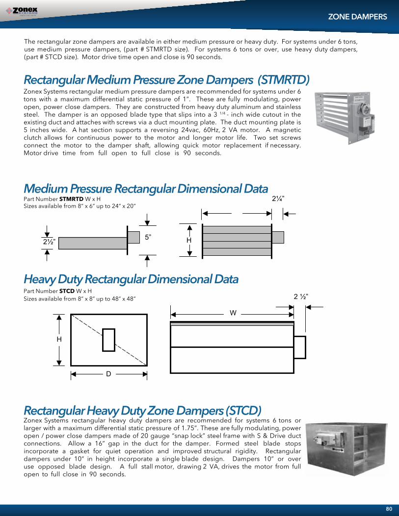
Rectangular Medium Pressure Zone Dampers (STMRTD)
Heavy Duty Rectangular Dimensional DataPart Number STCD W x HSizes available from 8” x 8” up to 48” x 48”
D
H
W
2 ”
Medium Pressure Rectangular Dimensional Data Part Number STMRTD W x HSizes available from 8” x 6” up to 24” x 20”
2 ”
2 ” 5” H
Zonex Systems rectangular medium pressure dampers are recommended for systems under 6 tons with a maximum differential static pressure of 1”. These are fully modulating, power open, power close dampers. They are constructed from heavy duty aluminum and stainless steel. The damper is an opposed blade type that slips into a 3 1/4 - inch wide cutout in the existing duct and attaches with screws via a duct mounting plate. The duct mounting plate is 5 inches wide. A hat section supports a reversing 24vac, 60Hz, 2 VA motor. A magnetic clutch allows for continuous power to the motor and longer motor life. Two set screws connect the motor to the damper shaft, allowing quick motor replacement if necessary. Motor drive time from full open to full close is 90 seconds.
Rectangular Heavy Duty Zone Dampers (STCD) Zonex Systems rectangular heavy duty dampers are recommended for systems 6 tons or larger with a maximum differential static pressure of 1.75”. These are fully modulating, power open / power close dampers made of 20 gauge “snap lock” steel frame with S & Drive duct connections. Allow a 16” gap in the duct for the damper. Formed steel blade stops incorporate a gasket for quiet operation and improved structural rigidity. Rectangular dampers under 10” in height incorporate a single blade design. Dampers 10” or over use opposed blade design. A full stall motor, drawing 2 VA, drives the motor from full open to full close in 90 seconds.
The rectangular zone dampers are available in either medium pressure or heavy duty. For systems under 6 tons, use medium pressure dampers, (part # STMRTD size). For systems 6 tons or over, use heavy duty dampers, (part # STCD size). Motor drive time open and close is 90 seconds.
ZONE DAMPERS
80

Rectangular Damper Capacities*
ZONE DAMPERS
WIDTH IN INCHES 8 10 12 14 16 18 20 22 24 26 28 30 32 34 36 38 40 42 44 46 48 8 300 400 500 610 710 820 925 1050 1175 1250 1400 1500 1600 1725 1825 2000 2100 2200 2275 2400 2525
10 400 540 680 825 975 1125 1300 1400 1590 1750 1975 2100 2175 2400 2600 2775 2900 3000 3200 3400 3600 12 500 680 850 1000 1200 1400 1600 1850 2000 2300 2550 2700 2850 3100 3400 3600 3800 3975 4200 4450 5775 14 610 825 1000 1250 1500 1750 2000 2250 2500 2900 3150 3425 3625 3825 4200 4600 4800 5000 5300 5750 600016 710 975 1200 1500 1800 2100 2450 2700 3000 3600 3950 4200 4425 4650 5100 5600 5780 6025 6500 7000 740018 820 1125 1400 1750 2100 2500 2850 3080 3600 4400 4600 4950 5100 5600 6000 6500 7000 7150 7600 8100 8600 20 925 1300 1600 2000 2450 2850 3400 3775 4000 4800 5500 5700 6000 6600 7100 7900 8025 8500 9000 9600 10075 22 1050 1400 1850 2250 2700 3080 3775 4300 4800 5100 6000 6350 6800 7200 7800 8600 9000 9600 10000 11500 12500 24 1175 1590 2000 2500 3000 3600 4000 4800 5400 6100 7000 7150 7600 8600 9100 10000 10700 11500 12000 13050 14700 26 1250 1750 2300 2900 3600 4400 4800 5100 6100 6700 7800 8400 8900 10000 10900 11075 12050 13000 14000 15000 15900 28 1400 1975 2550 3150 3950 4600 5500 6000 7000 7800 8400 9150 10000 10700 11900 13000 13800 14900 15200 16500 17500 30 1500 2100 2700 3425 4200 4950 5700 6350 7150 8400 9150 10000 11000 11800 12400 13800 14200 15000 16000 17400 18500 32 1600 2175 2850 3625 4425 5100 6000 6800 7600 8900 10000 11000 11250 12700 13900 14900 15200 16900 17300 19000 20500 34 1725 2400 3100 3825 4650 5600 6600 7200 8600 10000 10700 11800 12700 14100 15000 16500 17200 18100 19200 20500 21900 36 1825 2600 3400 4200 5100 6000 7100 7800 9100 10900 11900 12400 13900 15000 16100 17400 18500 20000 21500 22900 24200 38 2000 2775 3600 4600 5600 6500 7900 8600 10000 11075 13000 13800 14900 16500 17400 17800 20000 21900 22600 24000 25100 40 2100 2900 3800 4800 5780 7000 8025 9000 10700 12050 13800 14200 15200 17200 18500 20000 21000 22200 24900 25000 27000 42 2200 3000 3975 5000 6025 7150 8500 9600 11500 13000 14900 15000 16900 18100 20000 21900 22200 22800 25100 26900 30000 44 2275 3200 4200 5300 6500 7600 9000 10000 12000 14000 15200 16000 17300 19200 21500 22600 24900 25100 26500 30000 32000 46 2400 3400 4450 5750 7000 8100 9600 11500 13050 15000 16500 17400 19000 20500 22900 24000 25000 26900 30000 30500 32800 48 2525 3600 5775 6000 7400 8600 1075 12500 14700 15900 17500 18500 20500 21900 24200 25100 27000 30000 32000 32800 35600
* These air quantities were derived from duct sizing chart .1" friction loss per 100' of duct. All CF .etamixorppa era detsil sM For accurate selection use duct sizing table or
HEI
GH
T IN
INC
HES
81

SLAVING DAMPERS
Slaving More Than Three Zone Dampers
Slaving Up To Three Zone DampersUp to three dampers can be directly controlled by one EzTouchX. To wire two or three dampers for a zone, use the following wiring diagram. Remember to size the power transformer for the total number of zone dampers in the system, 2VA per damper.
When slaving more than three zone dampers, use the following diagram. An additional 24VAC and control relays are needed for these applications.Note: All slave dampers need to be model STMPD / STCD
82
ZONE DAMPER 2
MCRORC
ZONE DAMPER 1
MCRORC
STMPD or STCD damper STMPD or STCD damper
ZONE DAMPER 3
MCRORC
STMPD or STCD damper
AUXDS
COM
DS
TR1TR2
�� ��
� � � � �� � � � � � �� �
� � � � � �
� � � � �MCRORC
GND
AB
� � �� � �� � � � �
AUXDS
COM
DS
TR1TR2
�� ��
� � � � �� � � � � � �� �
� � � � � �
� � � � �MCRORC
GND
AB
ZONE DAMPER 4MC RO RC
ZONE DAMPER 2MC RO RC
ZONE DAMPER 3
MC RO RC
24 VOLTTRANSFORMER
CONTROLRELAYSPST
CONTROLRELAYSPST
ZONE DAMPER 1MC RO RC
STMPD or STCD damper STMPD or STCD damper STMPD or STCD damper STMPD or STCD damper
� � �� � �� � � � �

DIAMETER CFM 8” 560 10” 900 12” 1250 14” 1700 16” 2200 18” 2600
PART # SIZE D L W ST BP 08 8 8” 10” 11” ST BP 10 10 10” 12” 13” ST BP 12 12 12” 14” 15” ST BP 14 14 14” 16” 17” ST BP 16 16 16” 18” 19” ST BP 18 18 18” 23” 21”
ROUND BYPASS SELECTION TABLE
4”
H
D
W 48” MAXIMUM WIDTH
RECTANGULAR BYPASS DAMPERS SELECT FROM 8 x 8 thru 48 x 48
D
L
W
BYPASS DAMPERS – ELECTRONICwith integrated static pressure control
Electronic Bypass Dampers Modulating Bypass dampers are used to provide constant air delivery through the air handling unit. This is done by bypassing excess air from the supply duct back to the return duct. As a zone is satisfied, its zone damper closes. When this happens, the bypass damper modulates just enough to bypass the excess air. This will control static pressure and noise at the diffusers.
The Electronic Bypass Damper is used on any size system. The damper can be round (STBP) or rectangular (STCDBP) with integrated static pressure control; and multiple dampers can be slaved together.
Sizing Electronic Bypass Dampers The bypass damper is to be sized for the total system CFM @ 1500 FPM. System CFM should be calculated at 400 CFM per ton.
Example: A 5-ton system is rated at 2000 CFM (5x400 = 2000). When calculated at 1500 FPM, the bypass damper should be 16”. Never undersize the bypass damper.
Round Bypass Damper Selection The Zonex Systems STBP damper is used for round bypass applications. When you know the bypass CFM requirements, use the ROUND BYPASS SELECTION TABLE to confirm the round damper size.
NOTE: Multiple round dampers can be slaved from one static pressure control to provide the correct capacity. One large rectangular bypass damper may be used instead of multiple round dampers. See below.
Rectangular Bypass Damper Selection The Zonex Systems STCDBP WxH damper is used for rectangular bypass applications. These dampers are also sized for the total system CFM rated at 1500 FPM. Multiple dampers can be slaved from a single static pressure control.
20”22”24”
33004000
STRDBP20
4700STRDBP22STRDBP24
202224
20”22”24”
24”24”24” 27”
27”27”
83

RECTANGULAR BYPASS SELECTION TABLE
ROUND AND RECTANGULAR BYPASS DAMPER MOTORS
WIDTH IN INCHES 8 10 12 14 16 18 20 22 24 28 32 36 40 44 48
8 667 833 1000 1167 1333 1500 1667 1833 2000 2333 2667 3000 3333 3667 4000 10 833 1042 1250 1458 1667 1875 2083 2292 2500 2917 3333 3750 4167 4583 5000 12 1000 1250 1500 1750 2000 2250 2500 2750 3000 3500 4000 4500 5000 5500 6000 14 1167 1458 1750 2042 2333 2625 2917 3208 3500 4083 4667 5250 5833 6417 7000 16 1333 1667 2000 2333 2667 3000 3333 3667 4000 4667 5333 6000 6667 7333 8000 18 1500 1875 2250 2625 3000 3375 3750 4125 4500 5250 6000 6750 7500 8250 9000 20 1667 2083 2500 2917 3333 3750 4167 4583 5000 5833 6667 7500 8333 9167 10000 22 1833 2292 2750 3208 3667 4125 4583 5042 5500 6417 7333 8250 9167 10083 11000 24 2000 2500 3000 3500 4000 4500 5000 5500 6000 7000 8000 9000 10000 11000 12000 28 2333 2917 3500 4083 4667 5250 5833 6417 7000 8167 9333 10500 11667 12833 14000 32 2667 3333 4000 4667 5333 6000 6667 7333 8000 9333 10667 12000 13333 14667 16000 36 3000 3750 4500 5250 6000 6750 7500 8250 9000 10500 12000 13500 15000 16500 18000 40 3333 4167 5000 5833 6667 7500 8333 9167 10000 11667 13333 15000 16667 18333 20000 44 3667 4583 5500 6417 7333 8250 9167 10083 11000 12833 14667 16500 18333 20167 22000 48 4000 5000 6000 7000 8000 9000 10000 11000 12000 14000 16000 18000 20000 22000 24000
HEI
GH
T IN
INC
HES
RC RO MC
RC RO MC
DAMPER ACTUATOR
* * *
SLAVE DAMPER
ACTUATOR * * *
TO NEXT SLAVE BYPASS DAMPER IF APPLICABLE
RC RO MC
To Static Pressure Control, as shown on the Bypass Wiring Diagram on the next page.
Slaving Bypass Dampers Use only one Pressure Sensor when slaving two or more Bypass Dampers together. Connect the Pressure Sensor to one damper as described above. Connect the slave dampers in parallel as shown. Up to 4 dampers can be slaved to one Sensor. The slaved dampers will self-synchronize each time the dampers reach full open or full close.
Bypass air in CFM. Calculated at 1500 FPM. Formula used: B = W x H / 144 x 1500, where B = Bypass air in CFM, W = damper width in inches, H = damper height in inches, 144 = 144 sq. inches per sq. ft., 1500 = 1500 FPM.
84

INSTALLATIONThe round and rectangular bypass damper can be installed in any position. Do not run speed screws into damper housing. Screws may interfere with damper travel.
1. Install the bypass damper between the supply and return plenums of the unit. It must be the first tap off the supply plenum. (Bypass damper sizing is recommended for 100% of system CFM.)
2. Be sure the air flows through the damper in the proper direction as indicated by the arrow on the damper. Airflow is always from supply to return plenum.
3. Do not install the bypass damper outside.
4. Bypass damper and controller are powered by a dedicated 24vac 40VA transformer.
5. Follow the steps on the next page for Integrated Pressure Controller installation and set up.
BYPASS INSTALLATION
85
AIRFLOW
AIRFLOW
RETURN
BYPASS
HORIZONTAL APPLICATION
SHEET METALPIPE
SUPPLYPLENUM
A/C UNITOR
FURNACE
ROOFTOP INSTALLATION Down Discharge Application
A/C UNITOR
FURNACE
BYPASS
AIRFLOW
SHEET METALPIPE
RETURNPLENUM
SUPPLYPLENUM
ROOF LINE
OPEN RETURN PLENUM BYPASS APPLICATION
RETURN AIR GRILLE
AIR CONDITIONING
UNIT SUPPLY
DUCT
BYPASS DAMPER
To prevent bypass air fromflowing out the return grill,
use a short open endedreturn air plenum toconnect the bypassdamper to the unit.
OPEN RETURN PLENUM AND BYPASS APPLICATION
RETURN AIR GRILLE
SUPPLY DUCT
BYPASS DAMPER
AIR CONDITIONING
UNIT
ATTIC SPACE
ATTIC SPACE

IPC Installation
INTEGRATED STATIC PRESSURE CONTROL SETUP
Bypass Damper with Integrated Pressure Control is used to control bypass operations. The bypass damper modulates to maintain static pressure as zone dampers open and close. The bypass system reduces air noise from the supply registers caused by excessive air velocity. If the system is configured for intermittent fan mode and the system satisfies, there will be a 3-minute delay to allow for system purge, after which the bypass damper will open to 25%, preventing noisy rush of air through supply registers when fan starts up on a call for heat or cool. If the system is configured for fan continuous operation, the STBP (Round) or STCDBP (Rectangular) Electronic Bypass will monitor static pressure continuously, providing constant control of system static.
Integrated Pressure Control Description A. Supply air tube B. 24vac R and C C. Damper Terminal RO, RC, MC D. LED lights E. Adjustable Potentiometer F. TP1 Test Point
Locate the Integrated Pressure Control (IPC) and air tube on the bypass damper. Drill hole into the side of the supply duct 2’ after the bypass and before the 1st supply take-off.
Mount pressure supporting block over hole, align hole in block with hole in duct. Use provided sheet metal screws. Install air tube into supply air duct by slipping supplied plastic tubing into holes in support block and duct. Slip tube 3” into the duct. Pickup tubing fits snugly into provided hole. Connect pressure tube from static air pickup to Integrated Pressure Controller (port closest to you).
1.
2.
3.
4.
Bypass Damper With Integrated Bypass Control Setup Run all supply dampers to the full open position and have blower motor running at 100% fan speed. (See Note #1) Manually close the bypass damper by pressing in the release lever on the motor side of the actua-tor. With the release lever pressed, rotate the damper actuator collar to close the damper and release the lever to lock the damper closed. Quick Set Option: Turn the potentiometer on the damper control board to the full left position and slowly rotate RIGHT, until the “RC” RED LED turns on. Now rotate LEFT just slightly, until RC LED turns off. The IPC is ready for operation.
“RC” RED LED means damper closing.“RO” GREEN LED means damper opening.
1.
2.
3.
Fig. 1
Fig. 2
86

4.
Bypass Damper Wiring Diagram With Integrated Bypass Control
Static Pressure Voltage Chart
Static Pressure Option: The Integrated Pressure Control Board can be field configured for specified static pressure using a multi meter and the static pressure – voltage chart. (Exhibit A). This chart shows voltage (DC) to inches of W.C. (static pressure) relationship. Use a multi meter set on VDC and place the leads on the “C” terminal and “TP1” (test point one) next to the potentiometer. The Voltage reading translates to inches of W.C.
Bypass Checkout For Static Pressure Controller Make cool call at the zone thermostat of the smallest zone. Verify all zone dampers are closed except for calling zone. Verify noise at zone registers is not excessive. Adjust the Integrated Pressure Control LEFT to lower noise (airflow) or RIGHT to increase airflow until to noisy.
1.
2.
3.
Note # 1: To open all dampers, it may be necessary to remove Y outputs to unit on the zone control board and to make full cool calls on all thermostats. This will modulate dampers fully open and lock out compressor.
On GEN X use air balance mode on the mobile App for simplified bypass setup.
STATIC PRESSURE TP1 STATIC PRESSURE TP1
INCH W.C. VOLTAGE (DC) INCH W.C. VOLTAGE (DC)
0.10.150.2
0.250.3
0.350.4
0.45
0.50.550.6
0.650.7
0.750.8
1.491.621.691.811.851.911.942.06
2.222.272.422.482.6
2.682.81
EXHIBIT A
BYPASS DAMPER WITH INTEGRATED BYPASS CONTROL
Actuator Motor
IPC Controller24 volt 40va Transformer
24 volt SecondaryPrimary
RO RC MC RO RC MCRC
N/A N/A
INTEGRATED STATIC PRESSURE CONTROL SETUP
87

SYSTEM SETUP DIRECTORY
88

NETWORK ALL YOUR HVAC EQUIPMENTMonitor, update and control System Information from the mobile app
Designed to centralize control of
multiple constant volume VAV systems....................................................................................
H O T L I N E
(800) 228-2966....................................................................................
5622 Engineer DriveHuntington Beach, CA 92649Factory (714) 898-9963Fax (714) 898-6802
V I S I T O U R W E B S I T E
www.zonexproducts.comPATENTED PRODUCTZonex Systems reserves the right to discontinue, or change at any time, specifications or designs without notice and without incurring obligationsCopyright 2020 by Zonex Systems
.............................................................................................................................................................
PART # GENXMANJuly 2021
THE EASIEST WAY TO GET QUOTES FASTWWW.ZONEXPRODUCTS.COM