Network Administrator Guide API Version...
129
Amazon Virtual Private Cloud Network Administrator Guide API Version 2014-06-15
Transcript of Network Administrator Guide API Version...

Amazon Virtual Private CloudNetwork Administrator Guide
API Version 2014-06-15

Amazon Web Services
Amazon Virtual Private Cloud Network AdministratorGuide

Amazon Virtual Private Cloud: Network Administrator GuideAmazon Web ServicesCopyright © 2014 Amazon Web Services, Inc. and/or its affiliates. All rights reserved.
The following are trademarks of Amazon Web Services, Inc.: Amazon, Amazon Web Services Design, AWS, Amazon CloudFront,Cloudfront, Amazon DevPay, DynamoDB, ElastiCache, Amazon EC2, Amazon Elastic Compute Cloud, Amazon Glacier, Kindle, KindleFire, AWS Marketplace Design, Mechanical Turk, Amazon Redshift, Amazon Route 53, Amazon S3, Amazon VPC. In addition,Amazon.com graphics, logos, page headers, button icons, scripts, and service names are trademarks, or trade dress of Amazon inthe U.S. and/or other countries. Amazon's trademarks and trade dress may not be used in connection with any product or service thatis not Amazon's, in any manner that is likely to cause confusion among customers, or in any manner that disparages or discreditsAmazon.
All other trademarks not owned by Amazon are the property of their respective owners, who may or may not be affiliated with, connectedto, or sponsored by Amazon.
Amazon Virtual Private Cloud Network AdministratorGuide

Welcome ................................................................................................................................................. 1Your Customer Gateway ......................................................................................................................... 2Example: Cisco ASA Device ................................................................................................................. 12Example: Cisco IOS Device .................................................................................................................. 20Example: Cisco IOS Device (without BGP) .......................................................................................... 31Example: Juniper JunOS Device .......................................................................................................... 40Example: Juniper ScreenOS Device ..................................................................................................... 51Example: Yamaha Device ..................................................................................................................... 60Example: Generic Customer Gateway Using BGP ............................................................................... 69Example: Generic Customer Gateway (without BGP) .......................................................................... 77Troubleshooting .................................................................................................................................... 84Cisco ASA Customer Gateway Connectivity ........................................................................................ 84Cisco IOS Customer Gateway Connectivity ......................................................................................... 87Cisco IOS Customer Gateway Connectivity (without BGP) .................................................................. 92Juniper JunOS Customer Gateway Connectivity .................................................................................. 96Juniper ScreenOS Customer Gateway Connectivity .......................................................................... 100Yamaha Customer Gateway Connectivity ........................................................................................... 103Generic Device Customer Gateway Connectivity ............................................................................... 106Generic Device Customer Gateway Connectivity (without BGP) ........................................................ 108Configuring Windows Server 2008 R2 as a Customer Gateway for Your VPC ................................... 111Document History ............................................................................................................................... 125
API Version 2014-06-154
Amazon Virtual Private Cloud Network AdministratorGuide

Welcome
Welcome to the Amazon Virtual Private Cloud Network Administrator Guide. This guide is for customerswho plan to use an IPsec hardware VPN with their virtual private cloud (VPC). The topics in this guidehelp you configure your customer gateway, which is the device on your side of the VPN connection.
The VPN connection lets you bridge your VPC and IT infrastructure, and extend your existing securityand management policies to EC2 instances your VPC as if they were running within your own infrastructure.
For more information, see the following topics:
• Your Customer Gateway (p. 2)
• Example: Cisco ASA Device (p. 12)
• Example: Cisco IOS Device (p. 20)
• Example: Cisco IOS Device without Border Gateway Protocol (p. 31)
• Example: Juniper JunOS Device (p. 40)
• Example: Juniper ScreenOS Device (p. 51)
• Example:Yamaha Device (p. 60)
• Example: Generic Customer Gateway Using Border Gateway Protocol (p. 69)
• Example: Generic Customer Gateway without Border Gateway Protocol (p. 77)
• Configuring Windows Server 2008 R2 as a Customer Gateway for Your VPC (p. 111)
API Version 2014-06-151
Amazon Virtual Private Cloud Network AdministratorGuide

Your Customer Gateway
Topics
• Your Role (p. 2)
• What Is a Customer Gateway? (p. 2)
• Summary of What You Need to Do (p. 4)
• Determining Your Network Information (p. 4)
• Four Main Parts to Customer Gateway Configuration (p. 5)
• AWS VPN CloudHub and Redundant Customer Gateways (p. 6)
• Configuring Multiple VPN Connections to Your Amazon VPC (p. 6)
• Customer Gateway Devices We've Tested (p. 7)
• Requirements for Your Customer Gateway (p. 8)
• If You Have a Firewall Between the Internet and Your Customer Gateway (p. 10)
Your RoleThroughout this guide, we refer to your company's integration team, which is the person (or persons) atyour company working to integrate your infrastructure with Amazon VPC. This team might consist of justyou, or might not include you at all, depending on how your company allocates network engineeringresources.The important thing to know is that someone at your company must use the AWS ManagementConsole to get the information that you need to configure your customer gateway, and someone mustactually configure the customer gateway.Your company might have a separate team for each task (anintegration team that uses the AWS Management Console, and a separate network engineering groupthat has access to network devices and configures the customer gateway). Or your company might havea single person who does both tasks, or some other arrangement entirely.This guide assumes that you'resomeone in the network engineering group who receives information from your company's integrationteam so you can then configure the customer gateway device.
What Is a Customer Gateway?Your company has decided to use an optional Amazon VPC VPN connection that links your data center(or network) to your Amazon VPC virtual private cloud (VPC). A customer gateway is the anchor on yourside of that connection. It can be a physical or software appliance. The anchor on the AWS side of theVPN connection is called a virtual private gateway.
API Version 2014-06-152
Amazon Virtual Private Cloud Network AdministratorGuide
Your Role

The following diagram shows your network, the customer gateway, the VPN connection that goes to thevirtual private gateway, and the VPC. There are two lines between the customer gateway and virtualprivate gateway because the VPN connection consists of two tunnels. We chose this design to provideincreased availability for the Amazon VPC service. If there's a device failure within AWS, your VPNconnection automatically fails over to the second tunnel so that your access isn't interrupted. When youconfigure your customer gateway, it's important you configure both tunnels.
The address of the external interface for your customer gateway must be a static address.We recommendthat you don't put your customer gateway behind a device performing network address translation (NAT).
From time to time, AWS performs routine maintenance on the virtual private gateway. This maintenancemay disable one of the two tunnels of your VPN connection for a brief period of time.Your VPN connectionautomatically fails over to the second tunnel while this maintenance is performed.To ensure uninterruptedservice, it's important that you configure both tunnels.
To protect against a loss of connectivity if your customer gateway becomes unavailable, you can set upa second VPN connection. For more information, see Using Redundant VPN Connections to ProvideFailover.
API Version 2014-06-153
Amazon Virtual Private Cloud Network AdministratorGuide
What Is a Customer Gateway?

Summary of What You Need to DoThe overall process of setting up the VPN connection is covered in the Amazon Virtual Private CloudUser Guide. One task in the process is to configure the customer gateway.The following table summarizeswhat you need to do to configure the customer gateway.
Process for Configuring the Customer Gateway
Designate an appliance to act as your customer gateway (for more information, see CustomerGateway Devices We've Tested (p. 7) and Requirements for Your Customer Gateway (p. 8)).
1
Determine the following information about the customer gateway:
• The vendor (for example, Cisco Systems), the platform (for example, ISR Series Routers), andthe software version (for example, IOS 12.4)
• The Internet-routable IP address for the external interface.
NoteWe assume that the BGP ASN for the customer gateway is 65000.
2
Give the preceding information to your integration team. The integration team creates your VPNconnection and gets the information that you need to configure the customer gateway.
3
Get the configuration information from the integration team.4
Configure your customer gateway using the configuration information that you received from theintegration team.
5
Notify your integration team when you're done configuring the customer gateway.6
You can create additional VPN connections to other VPCs using the same customer gateway appliance.However, each VPN connection requires a separate public IP address on the customer gateway.
Determining Your Network InformationThe first task for your integration team is to determine the set of information in the following table. Thistable includes example values for some of the items.You can use the example values or determine realvalues.You must obtain real values for all the other items.
TipYou can print the table and fill in the values you plan to use in the column on the far right.
Your ValueCommentsHow UsedItem
Example:10.0.0.0/16Used in a customergateway configuration.
VPC CIDR block
Example:10.0.1.0/24Subnet #1 CIDR block(can be same as theCIDR block for the VPC)
Example:10.0.2.0/24(Optional) Subnet #2CIDR block
API Version 2014-06-154
Amazon Virtual Private Cloud Network AdministratorGuide
Summary of What You Need to Do

Your ValueCommentsHow UsedItem
(Optional) Subnet #NCIDR block
Used in an API call tospecify the format of thereturned information thatyou use to configure thecustomer gateway
Customer gateway type(for example, Cisco ISR,Juniper J-Series, orJuniper SSG)
The value must bestatic.
Used in customergateway configuration(referred to asYOUR_UPLINK_ADDRESS)
Internet-routable IPaddress of the customergateway's externalinterface
You can use an existingASN assigned to yournetwork. If you don'thave one, you can usea private ASN (in the64512–65534 range).For more informationabout ASNs, go to theWikipedia article.
Used in customergateway configurationfor devices that useBGP (referred to asYOUR_BGP_ASN)
(Optional) BorderGateway Protocol (BGP)Autonomous SystemNumber (ASN) of thecustomer gateway
If you have a firewall between your customer gateway and the Internet, see If You Have a Firewall Betweenthe Internet and Your Customer Gateway (p. 10).
Four Main Parts to Customer GatewayConfiguration
There are four main parts to the configuration of your customer gateway. Throughout this guide, we usea special symbol for each of these parts to help you understand what you need to do. The following tableshows the four parts and the corresponding symbols.
IKE Security Association (required to exchange keys used to establish the IPsec securityassociation)
IPsec Security Association (handles the tunnel's encryption, authentication, and so on.)
Tunnel interface (receives traffic going to and from the tunnel)
BGP peering (exchanges routes between the customer gateway and the virtual privategateway) for devices that use BGP
Optional
API Version 2014-06-155
Amazon Virtual Private Cloud Network AdministratorGuide
Four Main Parts to Customer Gateway Configuration

AWS VPN CloudHub and Redundant CustomerGateways
You can establish multiple VPN connections to a single virtual private gateway from multiple customergateways. This configuration can be used in different ways; you can have redundant customer gatewaysbetween your data center and your VPC, or you can have multiple locations connected to the AWS VPNCloudHub.
If you have redundant customer gateways, each customer gateway advertises the same prefix (forexample, 0.0.0.0/0) to the virtual private gateway. The gateways will be used in an active/active mode,but if one customer gateway fails, the virtual private gateway directs all traffic to the working customergateway.
If you use the AWS VPN CloudHub configuration, multiple sites can access your VPC or securely accesseach other using a simple hub-and-spoke model.You configure each customer gateway to advertise asite-specific prefix (such as 10.0.0.0/24, 10.0.1.0/24) to the virtual private gateway. The virtual privategateway routes traffic to the appropriate site and advertises the reachability of one site to all other sites.
To configure the AWS VPN CloudHub, use the AWS Management Console to create multiple customergateways, each with the unique public IP address of the gateway and a unique autonomous systemnumber (ASN). Then create a VPN connection from each customer gateway to a common VPN gateway.Use the instructions that follow to configure each customer gateway to connect to the virtual privategateway.
To enable instances in your VPC to reach the virtual private gateway (and then your customer gateways),you must configure routes in your VPC routing tables. For complete instructions, see the Amazon VirtualPrivate Cloud User Guide. For AWS VPN CloudHub, you can configure an aggregate route in your VPCrouting table (for example, 10.0.0.0/16), and use more specific prefixes between customer gateways andthe virtual private gateway.
Configuring Multiple VPN Connections to YourAmazon VPC
You can create up to ten VPN connections for your VPC.You can use multiple VPN connections to linkyour remote offices to the same VPC. For example, if you have offices in Los Angeles, Chicago, NewYork, and Miami, you can link each of these offices to your VPC.You can also use multiple VPNconnections to establish redundant customer gateways from a single location.
NoteIf you need more than ten VPN connections, complete the Request to Increase Amazon VPCLimits form to request an increased limit.
When you create multiple VPN connections, the virtual private gateway sends network traffic to theappropriate VPN connection using statically assigned routes or BGP route advertisements, dependingupon how the VPN connection was configured. Statically assigned routes are preferred over BGP advertisedroutes in cases where identical routes exist in the virtual private gateway.
When you have customer gateways at multiple geographic locations, each customer gateway shouldadvertise a unique set of IP ranges specific to the location. When you establish redundant customergateways at a single location, both gateways should advertise the same IP ranges.
The virtual private gateway receives routing information from all customer gateways and calculates theset of preferred paths using the BGP best path selection algorithm. The rules of that algorithm, as itapplies to VPC, are:
API Version 2014-06-156
Amazon Virtual Private Cloud Network AdministratorGuide
AWS VPN CloudHub and Redundant Customer Gateways

1. The most specific IP prefix is preferred (for example, 10.0.0.0/24 is preferable to 10.0.0.0/16)
2. When the prefixes are the same, statically configured VPN connections, if they exist, are preferred.For matching prefixes where each VPN connection uses BGP, the AS PATH is compared and theprefix with the shortest AS PATH is preferred. Alternatively, you can prepend AS_PATH, so that thepath is less preferred.
3. When the AS PATHs are the same length, the path origin is compared. Prefixes with an Interior GatewayProtocol (IGP) origin are preferred to Exterior Gateway Protocol (EGP) origins, which are preferred tounknown origins.
4. When the origins are the same, the router IDs of the advertising routes are compared. The lowestrouter ID is preferred.
5. When the router IDs are the same, the BGP peer IP addresses are compared. The lowest peer IPaddress is preferred.
The following diagram shows the configuration of multiple VPNs.
Customer Gateway Devices We've TestedYour customer gateway can be a physical or software appliance.
For information about the specific routers that we've tested, see What customer gateway devices areknown to work with Amazon VPC? in the Amazon VPC FAQ.
This guide presents information about how to configure the following devices:
• Cisco ASA running Cisco ASA 8.2 (or later) software
• Cisco IOS running Cisco IOS 12.4 (or later) software
• Juniper J-Series running JunOS 9.5 (or later) software
• Juniper SSG running ScreenOS 6.1, or 6.2 (or later) software
• Juniper ISG running ScreenOS 6.1, or 6.2 (or later) software
• Yamaha RT107e, RTX1200, RTX1500, RTX3000 and SRT100 routers
API Version 2014-06-157
Amazon Virtual Private Cloud Network AdministratorGuide
Customer Gateway Devices We've Tested

• Microsoft Windows Server 2008 R2 (or later) software
If you have one of these devices, but configure it for IPsec in a different way than presented in this guide,feel free to alter our suggested configuration to match your particular needs.
Requirements for Your Customer GatewayIf you have a device that isn't in the preceding list of tested devices, this section describes the requirementsthe device must meet for you to use it with Amazon VPC. The following table lists the requirement thecustomer gateway must adhere to, the related RFC (for reference), and comments about the requirement.For an example of the configuration information if your device isn't one of the tested Cisco or Juniperdevices, see Example: Generic Customer Gateway Using Border Gateway Protocol (p. 69).
To provide context for the following requirements, think of each VPN connection as consisting of twoseparate tunnels. Each tunnel contains an IKE Security Association, an IPsec Security Association, anda BGP Peering. Note that you are limited to 2 Security Associations (SAs), one inbound and one outbound.Some devices use policy-based VPN and will create as many SAs as ACL entries. Therefore, you mayneed to consolidate your rules and then filter so you don't permit unwanted traffic.
The VPN tunnel comes up when traffic is generated from your side of the VPN connection. The AWSendpoint is not the initiator; your customer gateway must initiate the tunnels.
CommentsRFCRequirement
The IKE Security Association is established first betweenthe virtual private gateway and customer gateway using thePre-Shared Key as the authenticator. Upon establishment,IKE negotiates an ephemeral key to secure future IKEmessages. Proper establishment of an IKE SecurityAssociation requires complete agreement among theparameters, including encryption and authenticationparameters.
RFC 2409Establish IKE SecurityAssociation usingPre-Shared Keys
Using the IKE ephemeral key, keys are established betweenthe virtual private gateway and customer gateway to forman IPsec Security Association (SA). Traffic betweengateways is encrypted and decrypted using this SA. Theephemeral keys used to encrypt traffic within the IPsec SAare automatically rotated by IKE on a regular basis to ensureconfidentiality of communications.
RFC 4301Establish IPsec SecurityAssociations in Tunnelmode
This encryption function is used to ensure privacy amongboth IKE and IPsec Security Associations.
RFC 3602Utilize the AES 128-bitencryption function
This hashing function is used to authenticate both IKE andIPsec Security Associations.
RFC 2404Utilize the SHA-1 hashingfunction
IKE uses Diffie-Hellman to establish ephemeral keys tosecure all communication between customer gateways andVPN gateways.
RFC 2409Utilize Diffie-HellmanPerfect Forward Secrecy in"Group 2" mode
API Version 2014-06-158
Amazon Virtual Private Cloud Network AdministratorGuide
Requirements for Your Customer Gateway

CommentsRFCRequirement
The use of Dead Peer Detection enables the VPN devicesto rapidly identify when a network condition preventsdelivery of packets across the Internet. When this occurs,the gateways delete the Security Associations and attemptto create new associations. During this process, thealternate IPsec tunnel is utilized if possible.
RFC 3706Utilize IPsec Dead PeerDetection
Your gateway must support the ability to bind the IPsectunnel to a logical interface. The logical interface containsan IP address used to establish BGP peering to the virtualprivate gateway. This logical interface should perform noadditional encapsulation (for example, GRE, IP in IP).Yourinterface should be set to a 1436 byte MaximumTransmission Unit (MTU). An MTU up to 1500 bytes issupported.
NoneBind tunnel to logicalinterface (route-based VPN)
When packets are too large to be transmitted, they mustbe fragmented. We will not reassemble fragmentedencrypted packets. Therefore, your VPN device mustfragment packets before encapsulating with the VPNheaders. The fragments are individually transmitted to theremote host, which reassembles them. For more informationabout fragmentation, see the Wikipedia article on IPfragmentation.
RFC 4459Fragment IP packets beforeencryption
BGP is used to exchange routes between the customergateway and virtual private gateway for devices that useBGP. All BGP traffic is encrypted and transmitted via theIPsec Security Association. BGP is required for bothgateways to exchange the IP prefixes reachable throughthe IPsec SA.
RFC 4271(Optional) Establish BGPpeerings
We recommend you use the techniques listed in the following table to minimize problems related to theamount of data that can be transmitted through the IPsec tunnel. Because the connection encapsulatespackets with additional network headers (including IPsec), the amount of data that can be transmitted ina single packet is reduced.
CommentsRFCTechnique
TCP packets are often the most prevalent type of packetacross IPsec tunnels. Some gateways have the ability tochange the TCP Maximum Segment Size parameter. Thiscauses the TCP endpoints (clients, servers) to reduce theamount of data sent with each packet. This is an idealapproach, as the packets arriving at the VPN devices aresmall enough to be encapsulated and transmitted.
RFC 4459Adjust the maximumsegment size of TCPpackets entering the VPNtunnel
API Version 2014-06-159
Amazon Virtual Private Cloud Network AdministratorGuide
Requirements for Your Customer Gateway

CommentsRFCTechnique
Some packets carry a flag, known as the Don't Fragment(DF) flag, that indicates that the packet should not befragmented. If the packets carry the flag, the gatewaysgenerate an ICMP Path MTU Exceeded message. In somecases, applications do not contain adequate mechanismsfor processing these ICMP messages and reducing theamount of data transmitted in each packet. Some VPNdevices have the ability to override the DF flag and fragmentpackets unconditionally as required. If your customergateway has this ability, we recommend that you use it asappropriate.
RFC 791Reset the "Don't Fragment"flag on packets
If You Have a Firewall Between the Internet andYour Customer Gateway
To use this service, you must have an Internet-routable IP address to use as the endpoint for the IPsectunnels connecting your customer gateway to the virtual private gateway. If a firewall is in place betweenthe Internet and your gateway, the rules in the following tables must be in place to establish the IPsectunnels. The virtual private gateway addresses are in the configuration information that you'll get fromthe integration team.
Inbound (from the Internet)
Input Rule I1
Virtual Private Gateway 1Source IP
Customer GatewayDest IP
UDPProtocol
500Source Port
500Destination
Input Rule I2
Virtual Private Gateway 2Source IP
Customer GatewayDest IP
UDPProtocol
500Source Port
500Destination Port
Input Rule I3
Virtual Private Gateway 1Source IP
Customer GatewayDest IP
API Version 2014-06-1510
Amazon Virtual Private Cloud Network AdministratorGuide
If You Have a Firewall Between the Internet and YourCustomer Gateway

IP 50 (ESP)Protocol
Input Rule I4
Virtual Private Gateway 2Source IP
Customer GatewayDest IP
IP 50 (ESP)Protocol
Outbound (to the Internet)
Output Rule O1
Customer GatewaySource IP
Virtual Private Gateway 1Dest IP
UDPProtocol
500Source Port
500Destination Port
Output Rule O2
Customer GatewaySource IP
Virtual Private Gateway 2Dest IP
UDPProtocol
500Source Port
500Destination Port
Output Rule O3
Customer GatewaySource IP
Virtual Private Gateway 1Dest IP
IP 50 (ESP)Protocol
Output Rule O4
Customer GatewaySource IP
Virtual Private Gateway 2Dest IP
IP 50 (ESP)Protocol
Rules I1, I2, O1, and O2 enable the transmission of IKE packets. Rules I3, I4, O3, and O4 enable thetransmission of IPsec packets containing the encrypted network traffic.
API Version 2014-06-1511
Amazon Virtual Private Cloud Network AdministratorGuide
If You Have a Firewall Between the Internet and YourCustomer Gateway

Example: Cisco ASA Device
Topics
• A High-Level View of the Customer Gateway (p. 12)
• An Example Configuration (p. 13)
• How to Test the Customer Gateway Configuration (p. 18)
In this section we walk you through an example of the configuration information provided by your integrationteam if your customer gateway is a Cisco ASA device running Cisco ASA software.
The diagram shows the high-level layout of the customer gateway.You should use the real configurationinformation that you receive from your integration team and apply it to your customer gateway.
A High-Level View of the Customer GatewayThe following diagram shows the general details of your customer gateway. Note that the VPN connectionconsists of two separate tunnels. Using redundant tunnels ensures continuous availability in the casethat a device fails.
API Version 2014-06-1512
Amazon Virtual Private Cloud Network AdministratorGuide
A High-Level View of the Customer Gateway

Please note that some Cisco ASAs only support Active/Standby mode.When you use these Cisco ASAs,you can have only one active tunnel at a time. The other standby tunnel becomes active if the first tunnelbecomes unavailable. With this redundancy, you should always have connectivity to your VPC throughone of the tunnels.
An Example ConfigurationThe configuration in this section is an example of the configuration information your integration teamshould provide. The example configuration contains a set of information for each of the tunnels that youmust configure.
The example configuration includes example values to help you understand how configuration works.For example, we provide example values for the VPN connection ID (vpn-12345678) and virtual privategateway ID (vgw-12345678), and placeholders for the AWS endpoints (AWS_ENDPOINT_1 andAWS_ENDPOINT_2).You'll replace these example values with the actual values from the configurationinformation that you receive.
In addition, you must:
• Configure the outside interface.
• Ensure that the Crypto ISAKMP Policy Sequence number is unique.
• Ensure that the Crypto List Policy Sequence number is unique.
• Ensure that the Crypto IPsec Transform Set and the Crypto ISAKMP Policy Sequence are harmoniouswith any other IPsec tunnels configured on the device.
• Ensure that the SLA monitoring number is unique.
• Configure all internal routing that moves traffic between the customer gateway and your local network.
API Version 2014-06-1513
Amazon Virtual Private Cloud Network AdministratorGuide
An Example Configuration
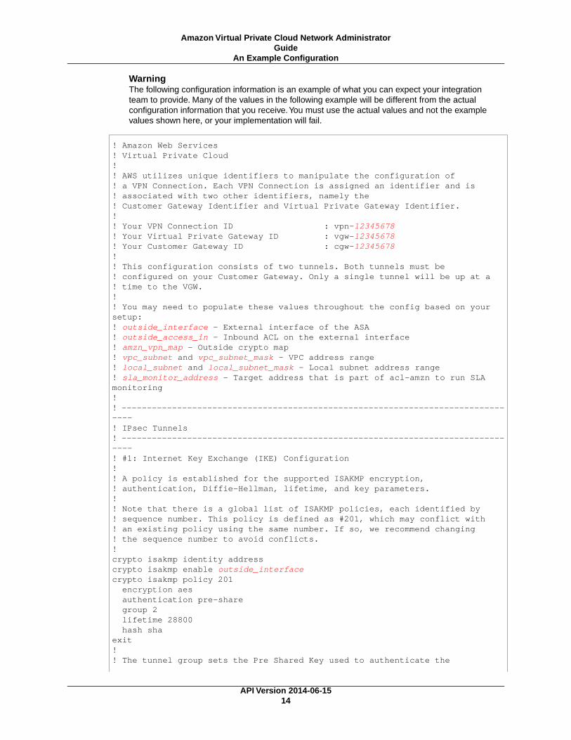
WarningThe following configuration information is an example of what you can expect your integrationteam to provide. Many of the values in the following example will be different from the actualconfiguration information that you receive.You must use the actual values and not the examplevalues shown here, or your implementation will fail.
! Amazon Web Services ! Virtual Private Cloud!! AWS utilizes unique identifiers to manipulate the configuration of ! a VPN Connection. Each VPN Connection is assigned an identifier and is ! associated with two other identifiers, namely the ! Customer Gateway Identifier and Virtual Private Gateway Identifier.!! Your VPN Connection ID : vpn-12345678! Your Virtual Private Gateway ID : vgw-12345678! Your Customer Gateway ID : cgw-12345678!! This configuration consists of two tunnels. Both tunnels must be ! configured on your Customer Gateway. Only a single tunnel will be up at a! time to the VGW.! ! You may need to populate these values throughout the config based on your setup:! outside_interface - External interface of the ASA! outside_access_in - Inbound ACL on the external interface! amzn_vpn_map - Outside crypto map! vpc_subnet and vpc_subnet_mask - VPC address range! local_subnet and local_subnet_mask - Local subnet address range! sla_monitor_address - Target address that is part of acl-amzn to run SLA monitoring! ! --------------------------------------------------------------------------------! IPsec Tunnels! --------------------------------------------------------------------------------! #1: Internet Key Exchange (IKE) Configuration!! A policy is established for the supported ISAKMP encryption, ! authentication, Diffie-Hellman, lifetime, and key parameters.!! Note that there is a global list of ISAKMP policies, each identified by ! sequence number. This policy is defined as #201, which may conflict with! an existing policy using the same number. If so, we recommend changing ! the sequence number to avoid conflicts.!crypto isakmp identity address crypto isakmp enable outside_interfacecrypto isakmp policy 201 encryption aes authentication pre-share group 2 lifetime 28800 hash shaexit!! The tunnel group sets the Pre Shared Key used to authenticate the
API Version 2014-06-1514
Amazon Virtual Private Cloud Network AdministratorGuide
An Example Configuration
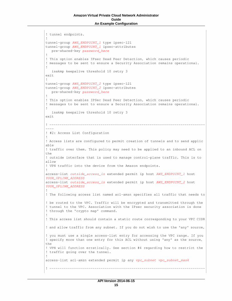
! tunnel endpoints.!tunnel-group AWS_ENDPOINT_1 type ipsec-l2ltunnel-group AWS_ENDPOINT_1 ipsec-attributes pre-shared-key password_here!! This option enables IPsec Dead Peer Detection, which causes periodic! messages to be sent to ensure a Security Association remains operational.! isakmp keepalive threshold 10 retry 3exit!tunnel-group AWS_ENDPOINT_2 type ipsec-l2ltunnel-group AWS_ENDPOINT_2 ipsec-attributes pre-shared-key password_here!! This option enables IPSec Dead Peer Detection, which causes periodic! messages to be sent to ensure a Security Association remains operational.! isakmp keepalive threshold 10 retry 3exit
! --------------------------------------------------------------------------------! #2: Access List Configuration! ! Access lists are configured to permit creation of tunnels and to send applic able ! traffic over them. This policy may need to be applied to an inbound ACL on the ! outside interface that is used to manage control-plane traffic. This is to allow ! VPN traffic into the device from the Amazon endpoints.!access-list outside_access_in extended permit ip host AWS_ENDPOINT_1 host YOUR_UPLINK_ADDRESSaccess-list outside_access_in extended permit ip host AWS_ENDPOINT_2 host YOUR_UPLINK_ADDRESS!! The following access list named acl-amzn specifies all traffic that needs to
! be routed to the VPC. Traffic will be encrypted and transmitted through the ! tunnel to the VPC. Association with the IPsec security association is done ! through the "crypto map" command.!! This access list should contain a static route corresponding to your VPC CIDR
! and allow traffic from any subnet. If you do not wish to use the "any" source,
! you must use a single access-list entry for accessing the VPC range. If you! specify more than one entry for this ACL without using "any" as the source, the ! VPN will function erratically. See section #4 regarding how to restrict the ! traffic going over the tunnel.!access-list acl-amzn extended permit ip any vpc_subnet vpc_subnet_mask
! ----------------------------------------------------------------------------
API Version 2014-06-1515
Amazon Virtual Private Cloud Network AdministratorGuide
An Example Configuration

----! #3: IPsec Configuration! ! The IPsec transform set defines the encryption, authentication, and IPsec! mode parameters.!crypto ipsec transform-set transform-amzn esp-aes esp-sha-hmac
! The crypto map references the IPsec transform set and further defines! the Diffie-Hellman group and security association lifetime. The mapping is ! created as #1, which may conflict with an existing crypto map using the same! number. If so, we recommend changing the mapping number to avoid conflicts.!crypto map amzn-vpn-map 1 match address acl-amzncrypto map amzn-vpn-map 1 set pfs group2crypto map amzn-vpn-map 1 set peer AWS_ENDPOINT_1 AWS_ENDPOINT_2crypto map amzn-vpn-map 1 set transform-set transform-amzn!! Only set this if you do not already have an outside crypto map, and it is not
! applied:!crypto map amzn-vpn-map interface outside_interface!! Additional parameters of the IPsec configuration are set here. Note that ! these parameters are global and therefore impact other IPsec ! associations.!! Set security association lifetime until it is renegotiated.crypto ipsec security-association lifetime seconds 3600!! This option instructs the firewall to clear the "Don't Fragment" ! bit from packets that carry this bit and yet must be fragmented, enabling! them to be fragmented.!crypto ipsec df-bit clear-df outside_interface!! This configures the gateway's window for accepting out of order! IPsec packets. A larger window can be helpful if too many packets ! are dropped due to reordering while in transit between gateways.!crypto ipsec security-association replay window-size 128!! This option instructs the firewall to fragment the unencrypted packets! (prior to encryption).!crypto ipsec fragmentation before-encryption outside_interface!! This option causes the firewall to reduce the Maximum Segment Size of! TCP packets to prevent packet fragmentation.sysopt connection tcpmss 1387!! In order to keep the tunnel in an active state, the ASA needs to send traffic
! to the subnet defined in acl-amzn. SLA monitoring can be configured to send pings ! to a destination in the subnet and keep the tunnel active. A possible destin ation
API Version 2014-06-1516
Amazon Virtual Private Cloud Network AdministratorGuide
An Example Configuration

! for the ping is the VPC Gateway IP, which is the first IP address in one of your ! subnets.! For example: a VPC with a CIDR range of 192.168.50.0/24 will have a gateway of ! 192.168.50.1.! The VPC Gateway IP doesn't respond; so the ping fails, but sending ! the ping keeps the tunnel active.!! The monitor is created as #1, which may conflict with an existing monitor using ! the same number. If so, we recommend changing the sequence number to avoid ! conflicts.!sla monitor 1 type echo protocol ipIcmpEcho sla_monitor_address interface outside_interface
frequency 5exitsla monitor schedule 1 life forever start-time now!! The firewall must allow icmp packets to use "sla monitor".icmp permit any outside_interface
!---------------------------------------------------------------------------------! #4: VPN Filter! The VPN Filter will restrict traffic that is permitted through the tunnels.
! This first entry provides an example to include traffic between your VPC Ad dress space and your office.! access-list amzn-filter extended permit ip vpc_subnet vpc_subnet_mask loc al_subnet local_subnet_mask! These remaining lines deny all traffic.! access-list amzn-filter extended deny ip any any! group-policy filter internal! group-policy filter attributes! vpn-filter value amzn-filter! tunnel-group AWS_ENDPOINT_1 general-attributes! default-group-policy filter! exit! tunnel-group AWS_ENDPOINT_2 general-attributes! default-group-policy filter! exit
!---------------------------------------------------------------------------------! #5: NAT Exemption! If you are performing NAT on the ASA you will have to add a nat exemption rule.! This varies depending on how NAT is set up. It should be configured along the ! lines of:! object network obj-SrcNet! subnet 0.0.0.0 0.0.0.0! object network obj-amzn! subnet vpc_subnet vpc_subnet_mask! nat (inside,outside) 1 source static obj-SrcNet obj-SrcNet destination static
API Version 2014-06-1517
Amazon Virtual Private Cloud Network AdministratorGuide
An Example Configuration

obj-amzn obj-amzn! If using version 8.2 or older, the entry would need to look something like this:! nat (inside) 0 access-list acl-amzn! Or, the same rule in acl-amzn should be included in an existing no NAT ACL.
How to Test the Customer GatewayConfiguration
When using Cisco ASA as a customer gateway, only one tunnel will be in the UP state.The second tunnelshould be configured, but will only be used if the first tunnel goes down. The second tunnel cannot be inthe UP state when the first tunnel is in the UP state.Your console will display a yellow dot and indicatethat only one tunnel is up and it will show the second tunnel as down. This is expected behavior for CiscoASA customer gateway tunnels because ASA as a customer gateway only supports a single tunnel beingup at one time.
You must first test the gateway configuration for each tunnel.
To test the customer gateway configuration for each tunnel
1. Ensure that the customer gateway has a static route to your VPC, as suggested in the configurationtemplates provided by AWS.
2. Ensure that a static route has been added to the VPN connection so that traffic can get back to yourcustomer gateway. For example, if your local subnet prefix is 198.10.0.0/16, you need to add astatic route with that CIDR range to your VPN connection. Make sure that both tunnels have a staticroute to your VPC.
Next you must test the connectivity for each tunnel.
ImportantFor the connectivity test to work, you must configure any security group or network ACL in yourVPC that filters traffic to the instance to allow inbound and outbound ICMP traffic.
To test the end-to-end connectivity of each tunnel
1. Launch an instance of one of the Amazon Linux AMIs into your VPC. The Amazon Linux AMIs arelisted in the launch wizard when you launch an instance from the AWS Management Console. Formore information, see the Amazon Virtual Private Cloud Getting Started Guide.
2. After the instance is running, get its private IP address (for example, 10.0.0.4).The console displaysthe address as part of the instance's details.
3. On a system in your home network, use the ping command with the instance's IP address. Makesure that the computer you ping from is behind the customer gateway. A successful response shouldbe similar to the following.
PROMPT> ping 10.0.0.4Pinging 10.0.0.4 with 32 bytes of data:
Reply from 10.0.0.4: bytes=32 time<1ms TTL=128Reply from 10.0.0.4: bytes=32 time<1ms TTL=128Reply from 10.0.0.4: bytes=32 time<1ms TTL=128
Ping statistics for 10.0.0.4:
API Version 2014-06-1518
Amazon Virtual Private Cloud Network AdministratorGuide
How to Test the Customer Gateway Configuration

Packets: Sent = 3, Received = 3, Lost = 0 (0% loss),
Approximate round trip times in milliseconds:Minimum = 0ms, Maximum = 0ms, Average = 0ms
NoteIf you ping an instance from your customer gateway router, ensure that you are sourcing pingmessages from an internal IP address, not a tunnel IP address. Some AMIs don't respond toping messages from tunnel IP addresses.
If your tunnels do not test successfully, see Troubleshooting Cisco ASA Customer GatewayConnectivity (p. 84).
API Version 2014-06-1519
Amazon Virtual Private Cloud Network AdministratorGuide
How to Test the Customer Gateway Configuration

Example: Cisco IOS Device
Topics
• A High-Level View of the Customer Gateway (p. 21)
• A Detailed View of the Customer Gateway and an Example Configuration (p. 22)
• How to Test the Customer Gateway Configuration (p. 29)
In this section we walk you through an example of the configuration information provided by your integrationteam if your customer gateway is a Cisco IOS device running Cisco IOS 12.4 (or later) software.
Two diagrams illustrate the example configuration. The first diagram shows the high-level layout of thecustomer gateway, and the second diagram shows details from the example configuration.You shoulduse the real configuration information that you receive from your integration team and apply it to yourcustomer gateway.
API Version 2014-06-1520
Amazon Virtual Private Cloud Network AdministratorGuide

A High-Level View of the Customer GatewayThe following diagram shows the general details of your customer gateway. Note that the VPN connectionconsists of two separate tunnels. Using redundant tunnels ensures continuous availability in the casethat a device fails.
API Version 2014-06-1521
Amazon Virtual Private Cloud Network AdministratorGuide
A High-Level View of the Customer Gateway

A Detailed View of the Customer Gateway andan Example Configuration
The diagram in this section illustrates an example Cisco IOS customer gateway. Following the diagramis a corresponding example of the configuration information your integration team should provide. Theexample configuration contains a set of information for each of the tunnels that you must configure.
In addition, the example configuration refers to these items that you must provide:
• YOUR_UPLINK_ADDRESS—The IP address for the Internet-routable external interface on the customergateway (which must be static, and can't be behind a device performing NAT)
• YOUR_BGP_ASN—The customer gateway's BGP ASN (we use 65000 by default)
The example configuration includes several example values to help you understand how configurationworks. For example, we provide example values for the VPN connection ID (vpn-44a8938f), virtual privategateway ID (vgw-8db04f81), the IP addresses (72.21.209.*, 169.254.255.*), and the remote ASN (7224).You'll replace these example values with the actual values from the configuration information that youreceive.
In addition, you must:
• Configure the outside interface
• Configure the tunnel interface IDs (referred to as Tunnel1 and Tunnel2 in the example configuration).
• Ensure that the Crypto ISAKMP Policy Sequence number is unique.
• Ensure that the Crypto IPsec Transform Set and the Crypto ISAKMP Policy Sequence are harmoniouswith any other IPsec tunnels configured on the device.
• Configure all internal routing that moves traffic between the customer gateway and your local network.
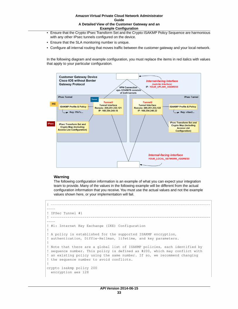
In the following diagram and example configuration, you must replace the items in red italics with valuesthat apply to your particular configuration.
API Version 2014-06-1522
Amazon Virtual Private Cloud Network AdministratorGuide
A Detailed View of the Customer Gateway and anExample Configuration

WarningThe following configuration information is an example of what you can expect your integrationteam to provide. Many of the values in the following example will be different from the actualconfiguration information that you receive.You must use the actual values and not the examplevalues shown here, or your implementation will fail.
! Amazon Web Services! Virtual Private Cloud
! AWS utilizes unique identifiers to manipulate the configuration of ! a VPN Connection. Each VPN Connection is assigned an identifier ! and is associated with two other identifiers, namely the ! Customer Gateway Identifier and Virtual Private Gateway Identifier.!! Your VPN Connection ID : vpn-44a8938f! Your Virtual Private Gateway ID : vgw-8db04f81! Your Customer Gateway ID : cgw-b4dc3961!!! This configuration consists of two tunnels. Both tunnels must be ! configured on your Customer Gateway.!! -------------------------------------------------------------------------! IPsec Tunnel #1! -------------------------------------------------------------------------
! #1: Internet Key Exchange (IKE) Configuration!! A policy is established for the supported ISAKMP encryption, ! authentication, Diffie-Hellman, lifetime, and key parameters.!! Note that there are a global list of ISAKMP policies, each identified by
API Version 2014-06-1523
Amazon Virtual Private Cloud Network AdministratorGuide
A Detailed View of the Customer Gateway and anExample Configuration

! sequence number. This policy is defined as #200, which may conflict with! an existing policy using the same number. If so, we recommend changing ! the sequence number to avoid conflicts.!crypto isakmp policy 200 encryption aes 128 authentication pre-share group 2 lifetime 28800 hash shaexit
! The ISAKMP keyring stores the Pre Shared Key used to authenticate the ! tunnel endpoints.!crypto keyring keyring-vpn-44a8938f-0 pre-shared-key address 72.21.209.225 key plain-text-password1exit
! An ISAKMP profile is used to associate the keyring with the particular ! endpoint.!crypto isakmp profile isakmp-vpn-44a8938f-0 match identity address 72.21.209.225 keyring keyring-vpn-44a8938f-0exit
! #2: IPsec Configuration! ! The IPsec transform set defines the encryption, authentication, and IPsec! mode parameters.!crypto ipsec transform-set ipsec-prop-vpn-44a8938f-0 esp-aes 128 esp-sha-hmac
mode tunnelexit
! The IPsec profile references the IPsec transform set and further defines! the Diffie-Hellman group and security association lifetime.!crypto ipsec profile ipsec-vpn-44a8938f-0 set pfs group2 set security-association lifetime seconds 3600 set transform-set ipsec-prop-vpn-44a8938f-0exit
! Additional parameters of the IPsec configuration are set here. Note that ! these parameters are global and therefore impact other IPsec ! associations.! This option instructs the router to clear the "Don't Fragment" ! bit from packets that carry this bit and yet must be fragmented, enabling! them to be fragmented.!crypto ipsec df-bit clear
! This option enables IPsec Dead Peer Detection, which causes periodic
API Version 2014-06-1524
Amazon Virtual Private Cloud Network AdministratorGuide
A Detailed View of the Customer Gateway and anExample Configuration

! messages to be sent to ensure a Security Association remains operational.!crypto isakmp keepalive 10 10 on-demand
! This configures the gateway's window for accepting out of order! IPsec packets. A larger window can be helpful if too many packets ! are dropped due to reordering while in transit between gateways.!crypto ipsec security-association replay window-size 128
! This option instructs the router to fragment the unencrypted packets! (prior to encryption).!crypto ipsec fragmentation before-encryption
! #3: Tunnel Interface Configuration! ! A tunnel interface is configured to be the logical interface associated ! with the tunnel. All traffic routed to the tunnel interface will be ! encrypted and transmitted to the VPC. Similarly, traffic from the VPC! will be logically received on this interface.!! Association with the IPsec security association is done through the ! "tunnel protection" command.!! The address of the interface is configured with the setup for your ! Customer Gateway. If the address changes, the Customer Gateway and VPN ! Connection must be recreated with Amazon VPC.!interface Tunnel1 ip address 169.254.255.2 255.255.255.252 ip virtual-reassembly tunnel source YOUR_UPLINK_ADDRESS tunnel destination 72.21.209.225 tunnel mode ipsec ipv4 tunnel protection ipsec profile ipsec-vpn-44a8938f-0 ! This option causes the router to reduce the Maximum Segment Size of ! TCP packets to prevent packet fragmentation. ip tcp adjust-mss 1396 no shutdownexit
! #4: Border Gateway Protocol (BGP) Configuration!
! BGP is used within the tunnel to exchange prefixes between the! Virtual Private Gateway and your Customer Gateway. The Virtual Private Gateway
! will announce the prefix corresponding to your VPC.! ! Your Customer Gateway may announce a default route (0.0.0.0/0), ! which can be done with the 'network' statement and ! 'default-originate' statements. !
API Version 2014-06-1525
Amazon Virtual Private Cloud Network AdministratorGuide
A Detailed View of the Customer Gateway and anExample Configuration
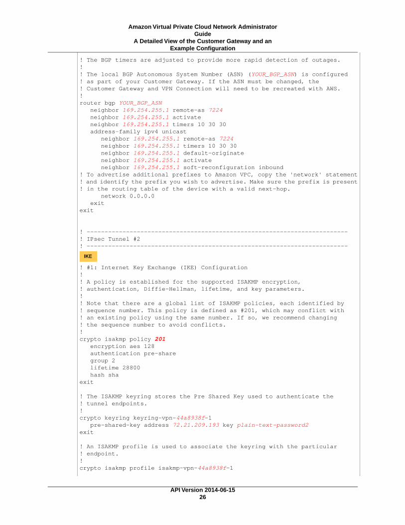
! The BGP timers are adjusted to provide more rapid detection of outages.!! The local BGP Autonomous System Number (ASN) (YOUR_BGP_ASN) is configured! as part of your Customer Gateway. If the ASN must be changed, the ! Customer Gateway and VPN Connection will need to be recreated with AWS.! router bgp YOUR_BGP_ASN neighbor 169.254.255.1 remote-as 7224 neighbor 169.254.255.1 activate neighbor 169.254.255.1 timers 10 30 30 address-family ipv4 unicast neighbor 169.254.255.1 remote-as 7224 neighbor 169.254.255.1 timers 10 30 30 neighbor 169.254.255.1 default-originate neighbor 169.254.255.1 activate neighbor 169.254.255.1 soft-reconfiguration inbound! To advertise additional prefixes to Amazon VPC, copy the 'network' statement! and identify the prefix you wish to advertise. Make sure the prefix is present! in the routing table of the device with a valid next-hop. network 0.0.0.0 exitexit
! -------------------------------------------------------------------------! IPsec Tunnel #2! -------------------------------------------------------------------------
! #1: Internet Key Exchange (IKE) Configuration!! A policy is established for the supported ISAKMP encryption, ! authentication, Diffie-Hellman, lifetime, and key parameters.!! Note that there are a global list of ISAKMP policies, each identified by ! sequence number. This policy is defined as #201, which may conflict with! an existing policy using the same number. If so, we recommend changing ! the sequence number to avoid conflicts.!crypto isakmp policy 201 encryption aes 128 authentication pre-share group 2 lifetime 28800 hash shaexit
! The ISAKMP keyring stores the Pre Shared Key used to authenticate the ! tunnel endpoints.!crypto keyring keyring-vpn-44a8938f-1 pre-shared-key address 72.21.209.193 key plain-text-password2exit
! An ISAKMP profile is used to associate the keyring with the particular ! endpoint.!crypto isakmp profile isakmp-vpn-44a8938f-1
API Version 2014-06-1526
Amazon Virtual Private Cloud Network AdministratorGuide
A Detailed View of the Customer Gateway and anExample Configuration

match identity address 72.21.209.193 keyring keyring-vpn-44a8938f-1exit
! #2: IPsec Configuration! ! The IPsec transform set defines the encryption, authentication, and IPsec! mode parameters.!crypto ipsec transform-set ipsec-prop-vpn-44a8938f-1 esp-aes 128 esp-sha-hmac
mode tunnelexit
! The IPsec profile references the IPsec transform set and further defines! the Diffie-Hellman group and security association lifetime.!crypto ipsec profile ipsec-vpn-44a8938f-1 set pfs group2 set security-association lifetime seconds 3600 set transform-set ipsec-prop-vpn-44a8938f-1exit
! Additional parameters of the IPsec configuration are set here. Note that ! these parameters are global and therefore impact other IPsec ! associations.! This option instructs the router to clear the "Don't Fragment" ! bit from packets that carry this bit and yet must be fragmented, enabling! them to be fragmented.!crypto ipsec df-bit clear
! This option enables IPsec Dead Peer Detection, which causes periodic! messages to be sent to ensure a Security Association remains operational.!crypto isakmp keepalive 10 10 on-demand
! This configures the gateway's window for accepting out of order! IPsec packets. A larger window can be helpful if too many packets ! are dropped due to reordering while in transit between gateways.!crypto ipsec security-association replay window-size 128
! This option instructs the router to fragment the unencrypted packets! (prior to encryption).!crypto ipsec fragmentation before-encryption
! #3: Tunnel Interface Configuration! ! A tunnel interface is configured to be the logical interface associated ! with the tunnel. All traffic routed to the tunnel interface will be ! encrypted and transmitted to the VPC. Similarly, traffic from the VPC! will be logically received on this interface.
API Version 2014-06-1527
Amazon Virtual Private Cloud Network AdministratorGuide
A Detailed View of the Customer Gateway and anExample Configuration

!! Association with the IPsec security association is done through the ! "tunnel protection" command.!! The address of the interface is configured with the setup for your ! Customer Gateway. If the address changes, the Customer Gateway and VPN ! Connection must be recreated with Amazon VPC.!interface Tunnel2 ip address 169.254.255.6 255.255.255.252 ip virtual-reassembly tunnel source YOUR_UPLINK_ADDRESS tunnel destination 72.21.209.193 tunnel mode ipsec ipv4 tunnel protection ipsec profile ipsec-vpn-44a8938f-1 ! This option causes the router to reduce the Maximum Segment Size of ! TCP packets to prevent packet fragmentation. ip tcp adjust-mss 1396 no shutdownexit
! #4: Border Gateway Protocol (BGP) Configuration!
! BGP is used within the tunnel to exchange prefixes between the! Virtual Private Gateway and your Customer Gateway. The Virtual Private Gateway
! will announce the prefix corresponding to your Cloud.! ! Your Customer Gateway may announce a default route (0.0.0.0/0), ! which can be done with the 'network' statement and ! 'default-originate' statements. !! The BGP timers are adjusted to provide more rapid detection of outages.!! The local BGP Autonomous System Number (ASN) (YOUR_BGP_ASN) is configured! as part of your Customer Gateway. If the ASN must be changed, the ! Customer Gateway and VPN Connection will need to be recreated with AWS.! router bgp YOUR_BGP_ASN neighbor 169.254.255.5 remote-as 7224 neighbor 169.254.255.5 activate neighbor 169.254.255.5 timers 10 30 30 address-family ipv4 unicast neighbor 169.254.255.5 remote-as 7224 neighbor 169.254.255.5 timers 10 30 30 neighbor 169.254.255.5 default-originate neighbor 169.254.255.5 activate neighbor 169.254.255.5 soft-reconfiguration inbound! To advertise additional prefixes to Amazon VPC, copy the 'network' statement! and identify the prefix you wish to advertise. Make sure the prefix is present! in the routing table of the device with a valid next-hop. network 0.0.0.0 exitexit
API Version 2014-06-1528
Amazon Virtual Private Cloud Network AdministratorGuide
A Detailed View of the Customer Gateway and anExample Configuration

How to Test the Customer GatewayConfiguration
You must first test the gateway configuration for each tunnel.
To test the customer gateway configuration for each tunnel
1. On your customer gateway, determine whether the BGP status is Active.It takes approximately 30 seconds for a BGP peering to become active.
2. Ensure that the customer gateway is advertising a route to the virtual private gateway. The routemay be the default route (0.0.0.0/0) or a more specific route you prefer.
When properly established, your BGP peering should be receiving one route from the virtual privategateway corresponding to the prefix that your VPC integration team specified for the VPC (for example,10.0.0.0/24). If the BGP peering is established, you are receiving a prefix, and you are advertising aprefix, your tunnel is configured correctly. Make sure that both tunnels are in this state.
Next you must test the connectivity for each tunnel.
ImportantFor the connectivity test to work, you must configure any security group or network ACL in yourVPC that filters traffic to the instance to allow inbound and outbound ICMP traffic.
To test the end-to-end connectivity of each tunnel
1. Launch an instance of one of the Amazon Linux AMIs into your VPC. The Amazon Linux AMIs arelisted in the launch wizard when you launch an instance from the AWS Management Console. Formore information, see the Amazon Virtual Private Cloud Getting Started Guide.
2. After the instance is running, get its private IP address (for example, 10.0.0.4).The console displaysthe address as part of the instance's details.
3. On a system in your home network, use the ping command with the instance's IP address. Makesure that the computer you ping from is behind the customer gateway. A successful response shouldbe similar to the following.
PROMPT> ping 10.0.0.4Pinging 10.0.0.4 with 32 bytes of data:
Reply from 10.0.0.4: bytes=32 time<1ms TTL=128Reply from 10.0.0.4: bytes=32 time<1ms TTL=128Reply from 10.0.0.4: bytes=32 time<1ms TTL=128
Ping statistics for 10.0.0.4:Packets: Sent = 3, Received = 3, Lost = 0 (0% loss),
Approximate round trip times in milliseconds:Minimum = 0ms, Maximum = 0ms, Average = 0ms
NoteIf you ping an instance from your customer gateway router, ensure that you are sourcing pingmessages from an internal IP address, not a tunnel IP address. Some AMIs don't respond toping messages from tunnel IP addresses.
API Version 2014-06-1529
Amazon Virtual Private Cloud Network AdministratorGuide
How to Test the Customer Gateway Configuration

If your tunnels don't test successfully, see Troubleshooting Cisco IOS Customer GatewayConnectivity (p. 87).
API Version 2014-06-1530
Amazon Virtual Private Cloud Network AdministratorGuide
How to Test the Customer Gateway Configuration

Example: Cisco IOS Device withoutBorder Gateway Protocol
Topics
• A High-Level View of the Customer Gateway (p. 31)
• A Detailed View of the Customer Gateway and an Example Configuration (p. 32)
• How to Test the Customer Gateway Configuration (p. 38)
In this section we walk you through an example of the configuration information provided by your integrationteam if your customer gateway is a Cisco Integrated Services router running Cisco IOS software.
Two diagrams illustrate the example configuration. The first diagram shows the high-level layout of thecustomer gateway, and the second diagram shows details from the example configuration.You shoulduse the real configuration information that you receive from your integration team, and apply it to yourcustomer gateway.
A High-Level View of the Customer GatewayThe following diagram shows the general details of your customer gateway. Note that the VPN connectionconsists of two separate tunnels. Using redundant tunnels ensures continuous availability in the casethat a device fails.
API Version 2014-06-1531
Amazon Virtual Private Cloud Network AdministratorGuide
A High-Level View of the Customer Gateway

A Detailed View of the Customer Gateway andan Example Configuration
The diagram in this section illustrates an example Cisco IOS customer gateway (without BGP). Followingthe diagram, there is a corresponding example of the configuration information that your integration teamshould provide. The example configuration contains a set of information for each of the tunnels that youmust configure.
In addition, the example configuration refers to this item that you must provide:
• YOUR_UPLINK_ADDRESS—The IP address for the Internet-routable external interface on the customergateway (which must be static, and can't be behind a device performing NAT)
The example configuration includes several example values to help you understand how configurationworks. For example, we provide example values for the VPN connection ID (vpn-12345678), virtual privategateway ID (vgw-12345678), the IP addresses (205.251.233.*, 169.254.255.*).You'll replace theseexample values with the actual values from the configuration information that you receive.
In addition, you must:
• Configure the outside interface.
• Configure the tunnel interface IDs (referred to as Tunnel1 and Tunnel2 in the example configuration).
• Ensure that the Crypto ISAKMP Policy Sequence number is unique.
API Version 2014-06-1532
Amazon Virtual Private Cloud Network AdministratorGuide
A Detailed View of the Customer Gateway and anExample Configuration
• Ensure that the Crypto IPsec Transform Set and the Crypto ISAKMP Policy Sequence are harmoniouswith any other IPsec tunnels configured on the device.
• Ensure that the SLA monitoring number is unique.
• Configure all internal routing that moves traffic between the customer gateway and your local network.
In the following diagram and example configuration, you must replace the items in red italics with valuesthat apply to your particular configuration.
WarningThe following configuration information is an example of what you can expect your integrationteam to provide. Many of the values in the following example will be different from the actualconfiguration information that you receive.You must use the actual values and not the examplevalues shown here, or your implementation will fail.
! --------------------------------------------------------------------------------! IPSec Tunnel #1! --------------------------------------------------------------------------------! #1: Internet Key Exchange (IKE) Configuration!! A policy is established for the supported ISAKMP encryption, ! authentication, Diffie-Hellman, lifetime, and key parameters.!! Note that there are a global list of ISAKMP policies, each identified by ! sequence number. This policy is defined as #200, which may conflict with! an existing policy using the same number. If so, we recommend changing ! the sequence number to avoid conflicts.!crypto isakmp policy 200 encryption aes 128
API Version 2014-06-1533
Amazon Virtual Private Cloud Network AdministratorGuide
A Detailed View of the Customer Gateway and anExample Configuration

authentication pre-share group 2 lifetime 28800 hash shaexit
! The ISAKMP keyring stores the Pre Shared Key used to authenticate the ! tunnel endpoints.!crypto keyring keyring-vpn-0 local-address CUSTOMER_IP pre-shared-key address 205.251.233.121 key PASSWORDexit
! An ISAKMP profile is used to associate the keyring with the particular ! endpoint.!crypto isakmp profile isakmp-vpn-0 local-address CUSTOMER_IP match identity address 205.251.233.121 keyring keyring-vpn-0exit
! #2: IPSec Configuration! ! The IPSec transform set defines the encryption, authentication, and IPSec! mode parameters.!crypto ipsec transform-set ipsec-prop-vpn-0 esp-aes 128 esp-sha-hmac mode tunnelexit
! The IPSec profile references the IPSec transform set and further defines! the Diffie-Hellman group and security association lifetime.!crypto ipsec profile ipsec-vpn-0 set pfs group2 set security-association lifetime seconds 3600 set transform-set ipsec-prop-vpn-0exit
! Additional parameters of the IPSec configuration are set here. Note that ! these parameters are global and therefore impact other IPSec ! associations.! This option instructs the router to clear the "Don't Fragment" ! bit from packets that carry this bit and yet must be fragmented, enabling! them to be fragmented.!crypto ipsec df-bit clear
! This option enables IPSec Dead Peer Detection, which causes periodic! messages to be sent to ensure a Security Association remains operational.!crypto isakmp keepalive 10 10 on-demand
! This configures the gateway's window for accepting out of order! IPSec packets. A larger window can be helpful if too many packets ! are dropped due to reordering while in transit between gateways.
API Version 2014-06-1534
Amazon Virtual Private Cloud Network AdministratorGuide
A Detailed View of the Customer Gateway and anExample Configuration

!crypto ipsec security-association replay window-size 128
! This option instructs the router to fragment the unencrypted packets! (prior to encryption).!crypto ipsec fragmentation before-encryption
! --------------------------------------------------------------------------------! #3: Tunnel Interface Configuration! ! A tunnel interface is configured to be the logical interface associated ! with the tunnel. All traffic routed to the tunnel interface will be ! encrypted and transmitted to the VPC. Similarly, traffic from the VPC! will be logically received on this interface.!! Association with the IPSec security association is done through the ! "tunnel protection" command.!! The address of the interface is configured with the setup for your ! Customer Gateway. If the address changes, the Customer Gateway and VPN ! Connection must be recreated with Amazon VPC.!interface Tunnel1 ip address 169.254.249.18 255.255.255.252 ip virtual-reassembly tunnel source CUSTOMER_IP tunnel destination 205.251.233.121 tunnel mode ipsec ipv4 tunnel protection ipsec profile ipsec-vpn-0 ! This option causes the router to reduce the Maximum Segment Size of ! TCP packets to prevent packet fragmentation. ip tcp adjust-mss 1387 no shutdownexit
! ----------------------------------------------------------------------------! #4 Static Route Configuration!! Your Customer Gateway needs to set a static route for the prefix corresponding to your ! VPC to send traffic over the tunnel interface.! An example for a VPC with the prefix 10.0.0.0/16 is provided below:! ip route 10.0.0.0 255.255.0.0 Tunnel1 track 100 !! SLA Monitor is used to provide a failover between the two tunnels. If the primary tunnel fails, the redundant tunnel will automatically be used! This sla is defined as #100, which may conflict with an existing sla using same number. ! If so, we recommend changing the sequence number to avoid conflicts.!ip sla 100 icmp-echo 169.254.249.17 source-interface Tunnel1 timeout 1000 frequency 5exit
API Version 2014-06-1535
Amazon Virtual Private Cloud Network AdministratorGuide
A Detailed View of the Customer Gateway and anExample Configuration

ip sla schedule 100 life forever start-time nowtrack 100 ip sla 100 reachability ! --------------------------------------------------------------------------------! --------------------------------------------------------------------------------! IPSec Tunnel #2! --------------------------------------------------------------------------------! #1: Internet Key Exchange (IKE) Configuration!! A policy is established for the supported ISAKMP encryption, ! authentication, Diffie-Hellman, lifetime, and key parameters.!! Note that there are a global list of ISAKMP policies, each identified by ! sequence number. This policy is defined as #201, which may conflict with! an existing policy using the same number. If so, we recommend changing ! the sequence number to avoid conflicts.!crypto isakmp policy 201 encryption aes 128 authentication pre-share group 2 lifetime 28800 hash shaexit
! The ISAKMP keyring stores the Pre Shared Key used to authenticate the ! tunnel endpoints.!crypto keyring keyring-vpn-1 local-address CUSTOMER_IP pre-shared-key address 205.251.233.122 key PASSWORDexit
! An ISAKMP profile is used to associate the keyring with the particular ! endpoint.!crypto isakmp profile isakmp-vpn-1 local-address CUSTOMER_IP match identity address 205.251.233.122 keyring keyring-vpn-1exit
! #2: IPSec Configuration! ! The IPSec transform set defines the encryption, authentication, and IPSec! mode parameters.!crypto ipsec transform-set ipsec-prop-vpn-1 esp-aes 128 esp-sha-hmac mode tunnelexit
! The IPSec profile references the IPSec transform set and further defines! the Diffie-Hellman group and security association lifetime.!crypto ipsec profile ipsec-vpn-1 set pfs group2
API Version 2014-06-1536
Amazon Virtual Private Cloud Network AdministratorGuide
A Detailed View of the Customer Gateway and anExample Configuration

set security-association lifetime seconds 3600 set transform-set ipsec-prop-vpn-1exit
! Additional parameters of the IPSec configuration are set here. Note that ! these parameters are global and therefore impact other IPSec ! associations.! This option instructs the router to clear the "Don't Fragment" ! bit from packets that carry this bit and yet must be fragmented, enabling! them to be fragmented.!crypto ipsec df-bit clear
! This option enables IPSec Dead Peer Detection, which causes periodic! messages to be sent to ensure a Security Association remains operational.!crypto isakmp keepalive 10 10 on-demand
! This configures the gateway's window for accepting out of order! IPSec packets. A larger window can be helpful if too many packets ! are dropped due to reordering while in transit between gateways.!crypto ipsec security-association replay window-size 128
! This option instructs the router to fragment the unencrypted packets! (prior to encryption).!crypto ipsec fragmentation before-encryption
! --------------------------------------------------------------------------------! #3: Tunnel Interface Configuration! ! A tunnel interface is configured to be the logical interface associated ! with the tunnel. All traffic routed to the tunnel interface will be ! encrypted and transmitted to the VPC. Similarly, traffic from the VPC! will be logically received on this interface.!! Association with the IPSec security association is done through the ! "tunnel protection" command.!! The address of the interface is configured with the setup for your ! Customer Gateway. If the address changes, the Customer Gateway and VPN ! Connection must be recreated with Amazon VPC.!interface Tunnel2 ip address 169.254.249.22 255.255.255.252 ip virtual-reassembly tunnel source CUSTOMER_IP tunnel destination 205.251.233.122 tunnel mode ipsec ipv4 tunnel protection ipsec profile ipsec-vpn-1 ! This option causes the router to reduce the Maximum Segment Size of ! TCP packets to prevent packet fragmentation. ip tcp adjust-mss 1387 no shutdownexit
API Version 2014-06-1537
Amazon Virtual Private Cloud Network AdministratorGuide
A Detailed View of the Customer Gateway and anExample Configuration

! ----------------------------------------------------------------------------! #4 Static Route Configuration!! Your Customer Gateway needs to set a static route for the prefix corresponding to your ! VPC to send traffic over the tunnel interface.! An example for a VPC with the prefix 10.0.0.0/16 is provided below:! ip route 10.0.0.0 255.255.0.0 Tunnel2 track 200 !! SLA Monitor is used to provide a failover between the two tunnels. If the primary tunnel fails, the redundant tunnel will automatically be used! This sla is defined as #200, which may conflict with an existing sla using same number. ! If so, we recommend changing the sequence number to avoid conflicts.!ip sla 200 icmp-echo 169.254.249.21 source-interface Tunnel2 timeout 1000 frequency 5exitip sla schedule 200 life forever start-time nowtrack 200 ip sla 200 reachability ! --------------------------------------------------------------------------------
How to Test the Customer GatewayConfiguration
You must first test the gateway configuration for each tunnel.
To test the customer gateway configuration for each tunnel
1. Ensure that the customer gateway has a static route to your VPC, as suggested in the configurationtemplates provided by AWS.
2. Ensure that a static route has been added to the VPN connection so that traffic can get back to yourcustomer gateway. For example, if your local subnet prefix is 198.10.0.0/16, you need to add astatic route with that CIDR range to your VPN connection. Make sure that both tunnels have a staticroute to your VPC.
Next you must test the connectivity for each tunnel.
ImportantFor the connectivity test to work, you must configure any security group or network ACL in yourVPC that filters traffic to the instance to allow inbound and outbound ICMP traffic.
To test the end-to-end connectivity of each tunnel
1. Launch an instance of one of the Amazon Linux AMIs into your VPC. The Amazon Linux AMIs arelisted in the launch wizard when you launch an instance from the AWS Management Console. Formore information, see the Amazon Virtual Private Cloud Getting Started Guide.
2. After the instance is running, get its private IP address (for example, 10.0.0.4).The console displaysthe address as part of the instance's details.
API Version 2014-06-1538
Amazon Virtual Private Cloud Network AdministratorGuide
How to Test the Customer Gateway Configuration

3. On a system in your home network, use the ping command with the instance's IP address. Makesure that the computer you ping from is behind the customer gateway. A successful response shouldbe similar to the following.
PROMPT> ping 10.0.0.4Pinging 10.0.0.4 with 32 bytes of data:
Reply from 10.0.0.4: bytes=32 time<1ms TTL=128Reply from 10.0.0.4: bytes=32 time<1ms TTL=128Reply from 10.0.0.4: bytes=32 time<1ms TTL=128
Ping statistics for 10.0.0.4:Packets: Sent = 3, Received = 3, Lost = 0 (0% loss),
Approximate round trip times in milliseconds:Minimum = 0ms, Maximum = 0ms, Average = 0ms
NoteIf you ping an instance from your customer gateway router, ensure that you are sourcing pingmessages from an internal IP address, not a tunnel IP address. Some AMIs don't respond toping messages from tunnel IP addresses.
If your tunnels don't test successfully, see Troubleshooting Cisco IOS Customer Gateway without BorderGateway Protocol Connectivity (p. 92).
API Version 2014-06-1539
Amazon Virtual Private Cloud Network AdministratorGuide
How to Test the Customer Gateway Configuration

Example: Juniper JunOS Device
Topics
• A High-Level View of the Customer Gateway (p. 41)
• A Detailed View of the Customer Gateway and an Example Configuration (p. 42)
• How to Test the Customer Gateway Configuration (p. 49)
In this section we walk you through an example of the configuration information provided by your integrationteam if your customer gateway is a Juniper J-Series router running JunOS 9.5 (or later) software.
Two diagrams illustrate the example configuration. The first diagram shows the high-level layout of thecustomer gateway, and the second diagram shows details from the example configuration.You shoulduse the real configuration information that you receive from your integration team and apply it to yourcustomer gateway.
API Version 2014-06-1540
Amazon Virtual Private Cloud Network AdministratorGuide

A High-Level View of the Customer GatewayThe following diagram shows the general details of your customer gateway. Note that the VPN connectionconsists of two separate tunnels. Using redundant tunnels ensures continuous availability in the casethat a device fails.
API Version 2014-06-1541
Amazon Virtual Private Cloud Network AdministratorGuide
A High-Level View of the Customer Gateway

A Detailed View of the Customer Gateway andan Example Configuration
The diagram in this section illustrates an example Juniper JunOS customer gateway. Following thediagram, there is a corresponding example of the configuration information your integration team shouldprovide. The example configuration contains a set of information for each of the tunnels that you mustconfigure.
In addition, the example configuration refers to these items that you must provide:
• YOUR_UPLINK_ADDRESS—The IP address for the Internet-routable external interface on the customergateway (which must be static, and can't be behind a device performing NAT)
• YOUR_BGP_ASN—The customer gateway's BGP ASN (we use 65000 by default)
The example configuration includes several example values to help you understand how configurationworks. For example, we provide example values for the VPN connection ID (vpn-44a8938f), virtual privategateway ID (vgw-8db04f81), the IP addresses (72.21.209.*, 169.254.255.*), and the remote ASN (7224).You'll replace these example values with the actual values from the configuration information that youreceive.
In addition, you must:
• Configure the outside interface (referred to as ge-0/0/0.0 in the example configuration).
• Configure the tunnel interface IDs (referred to as st0.1 and st0.2 in the example configuration).
• Configure all internal routing that moves traffic between the customer gateway and your local network.
• Identify the security zone for the uplink interface (the following configuration information uses the default"untrust" zone).
• Identify the security zone for the inside interface (the following configuration information uses the default"trust" zone).
In the following diagram and example configuration, you must replace the items in red italics with valuesthat apply to your particular configuration.
API Version 2014-06-1542
Amazon Virtual Private Cloud Network AdministratorGuide
A Detailed View of the Customer Gateway and anExample Configuration
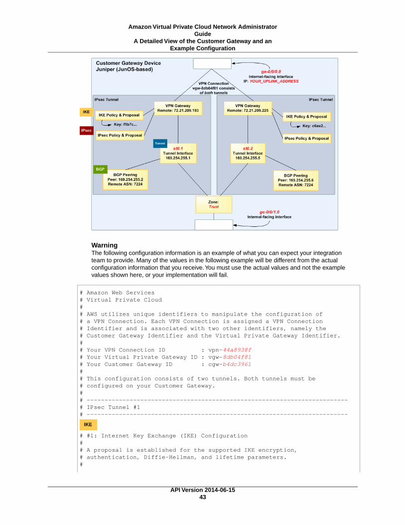
WarningThe following configuration information is an example of what you can expect your integrationteam to provide. Many of the values in the following example will be different from the actualconfiguration information that you receive.You must use the actual values and not the examplevalues shown here, or your implementation will fail.
# Amazon Web Services# Virtual Private Cloud## AWS utilizes unique identifiers to manipulate the configuration of # a VPN Connection. Each VPN Connection is assigned a VPN Connection # Identifier and is associated with two other identifiers, namely the # Customer Gateway Identifier and the Virtual Private Gateway Identifier.## Your VPN Connection ID : vpn-44a8938f# Your Virtual Private Gateway ID : vgw-8db04f81# Your Customer Gateway ID : cgw-b4dc3961## This configuration consists of two tunnels. Both tunnels must be # configured on your Customer Gateway.## -------------------------------------------------------------------------# IPsec Tunnel #1# -------------------------------------------------------------------------
# #1: Internet Key Exchange (IKE) Configuration## A proposal is established for the supported IKE encryption, # authentication, Diffie-Hellman, and lifetime parameters.#
API Version 2014-06-1543
Amazon Virtual Private Cloud Network AdministratorGuide
A Detailed View of the Customer Gateway and anExample Configuration

set security ike proposal ike-prop-vpn-44a8938f-1 authentication-method pre-shared-keys set security ike proposal ike-prop-vpn-44a8938f-1 authentication-algorithm sha1set security ike proposal ike-prop-vpn-44a8938f-1 encryption-algorithm aes-128-cbcset security ike proposal ike-prop-vpn-44a8938f-1 lifetime-seconds 28800set security ike proposal ike-prop-vpn-44a8938f-1 dh-group group2
# An IKE policy is established to associate a Pre Shared Key with the # defined proposal.#set security ike policy ike-pol-vpn-44a8938f-1 mode main set security ike policy ike-pol-vpn-44a8938f-1 proposals ike-prop-vpn-44a8938f-0set security ike policy ike-pol-vpn-44a8938f-1 pre-shared-key ascii-text plain-text-password1
# The IKE gateway is defined to be the Virtual Private Gateway. The gateway # configuration associates a local interface, remote IP address, and# IKE policy.## This example shows the outside of the tunnel as interface ge-0/0/0.0.# This should be set to the interface that IP address YOUR_UPLINK_ADDRESS is# associated with.# This address is configured with the setup for your Customer Gateway.## If the address changes, the Customer Gateway and VPN Connection must # be recreated.set security ike gateway gw-vpn-44a8938f-1 ike-policy ike-pol-vpn-44a8938f-0set security ike gateway gw-vpn-44a8938f-1 external-interface ge-0/0/0.0set security ike gateway gw-vpn-44a8938f-1 address 72.21.209.225
# Troubleshooting IKE connectivity can be aided by enabling IKE tracing.# The configuration below will cause the router to log IKE messages to# the 'kmd' log. Run 'show messages kmd' to retrieve these logs.# set security ike traceoptions file kmd# set security ike traceoptions file size 1024768# set security ike traceoptions file files 10# set security ike traceoptions flag all
# #2: IPsec Configuration## The IPsec proposal defines the protocol, authentication, encryption, and# lifetime parameters for our IPsec security association.#set security ipsec proposal ipsec-prop-vpn-44a8938f-1 protocol espset security ipsec proposal ipsec-prop-vpn-44a8938f-1 authentication-algorithm hmac-sha1-96set security ipsec proposal ipsec-prop-vpn-44a8938f-1 encryption-algorithm aes-128-cbcset security ipsec proposal ipsec-prop-vpn-44a8938f-1 lifetime-seconds 3600
# The IPsec policy incorporates the Diffie-Hellman group and the IPsec# proposal.#set security ipsec policy ipsec-pol-vpn-44a8938f-1 perfect-forward-secrecy keys group2
API Version 2014-06-1544
Amazon Virtual Private Cloud Network AdministratorGuide
A Detailed View of the Customer Gateway and anExample Configuration

set security ipsec policy ipsec-pol-vpn-44a8938f-1 proposals ipsec-prop-vpn-44a8938f-0
# A security association is defined here. The IPsec Policy and IKE gateways# are associated with a tunnel interface (st0.1).# The tunnel interface ID is assumed; if other tunnels are defined on# your router, you will need to specify a unique interface name # (for example, st0.10).#set security ipsec vpn vpn-44a8938f-1 bind-interface st0.1set security ipsec vpn vpn-44a8938f-1 ike gateway gw-vpn-44a8938f-0set security ipsec vpn vpn-44a8938f-1 ike ipsec-policy ipsec-pol-vpn-44a8938f-0set security ipsec vpn vpn-44a8938f-1 df-bit clear
# This option enables IPsec Dead Peer Detection, which causes periodic# messages to be sent to ensure a Security Association remains operational.#set security ike gateway gw-vpn-44a8938f-1 dead-peer-detection
# #3: Tunnel Interface Configuration#
# The tunnel interface is configured with the internal IP address.#set interfaces st0.1 family inet address 169.254.255.2/30set interfaces st0.1 family inet mtu 1436set security zones security-zone trust interfaces st0.1
# The security zone protecting external interfaces of the router must be # configured to allow IKE traffic inbound.#set security zones security-zone untrust host-inbound-traffic system-services ike
# The security zone protecting internal interfaces (including the logical # tunnel interfaces) must be configured to allow BGP traffic inbound.#set security zones security-zone trust host-inbound-traffic protocols bgp
# This option causes the router to reduce the Maximum Segment Size of# TCP packets to prevent packet fragmentation.#set security flow tcp-mss ipsec-vpn mss 1396
# #4: Border Gateway Protocol (BGP) Configuration#
# BGP is used within the tunnel to exchange prefixes between the# Virtual Private Gateway and your Customer Gateway. The Virtual Private Gateway
# will announce the prefix corresponding to your VPC.# # Your Customer Gateway may announce a default route (0.0.0.0/0), # which can be done with the EXPORT-DEFAULT policy. Only one prefix is
API Version 2014-06-1545
Amazon Virtual Private Cloud Network AdministratorGuide
A Detailed View of the Customer Gateway and anExample Configuration

# accepted by the Virtual Private Gateway.#
# The BGP timers are adjusted to provide more rapid detection of outages.
# # The local BGP Autonomous System Number (ASN) (YOUR_BGP_ASN) is configured# as part of your Customer Gateway. If the ASN must be changed, the # Customer Gateway and VPN Connection will need to be recreated with AWS.## We establish a basic route policy to export a default route to the# Virtual Private Gateway. #set policy-options policy-statement EXPORT-DEFAULT term default from route-filter 0.0.0.0/0 exact
set policy-options policy-statement EXPORT-DEFAULT term default then accept
set policy-options policy-statement EXPORT-DEFAULT term reject then reject
set protocols bgp group ebgp type external
set protocols bgp group ebgp neighbor 169.254.255.1 export EXPORT-DEFAULT set protocols bgp group ebgp neighbor 169.254.255.1 peer-as 7224set protocols bgp group ebgp neighbor 169.254.255.1 hold-time 30set protocols bgp group ebgp neighbor 169.254.255.1 local-as YOUR_BGP_ASN
# -------------------------------------------------------------------------# IPsec Tunnel #2# -------------------------------------------------------------------------
# #1: Internet Key Exchange (IKE) Configuration## A proposal is established for the supported IKE encryption, # authentication, Diffie-Hellman, and lifetime parameters.#set security ike proposal ike-prop-vpn-44a8938f-2 authentication-method pre-shared-keys set security ike proposal ike-prop-vpn-44a8938f-2 authentication-algorithm sha1set security ike proposal ike-prop-vpn-44a8938f-2 encryption-algorithm aes-128-cbcset security ike proposal ike-prop-vpn-44a8938f-2 lifetime-seconds 28800set security ike proposal ike-prop-vpn-44a8938f-2 dh-group group2
# An IKE policy is established to associate a Pre Shared Key with the # defined proposal.#set security ike policy ike-pol-vpn-44a8938f-2 mode main set security ike policy ike-pol-vpn-44a8938f-2 proposals ike-prop-vpn-44a8938f-2set security ike policy ike-pol-vpn-44a8938f-2 pre-shared-key ascii-text plain-text-password2
# The IKE gateway is defined to be the Virtual Private Gateway. The gateway # configuration associates a local interface, remote IP address, and# IKE policy.## This example shows the outside of the tunnel as interface ge-0/0/0.0.
API Version 2014-06-1546
Amazon Virtual Private Cloud Network AdministratorGuide
A Detailed View of the Customer Gateway and anExample Configuration

# This should be set to the interface that IP address YOUR_UPLINK_ADDRESS is# associated with.# This address is configured with the setup for your Customer Gateway.## If the address changes, the Customer Gateway and VPN Connection must be recre ated.#set security ike gateway gw-vpn-44a8938f-2 ike-policy ike-pol-vpn-44a8938f-1set security ike gateway gw-vpn-44a8938f-2 external-interface ge-0/0/0.0set security ike gateway gw-vpn-44a8938f-2 address 72.21.209.193
# Troubleshooting IKE connectivity can be aided by enabling IKE tracing.# The configuration below will cause the router to log IKE messages to# the 'kmd' log. Run 'show messages kmd' to retrieve these logs.# set security ike traceoptions file kmd# set security ike traceoptions file size 1024768# set security ike traceoptions file files 10# set security ike traceoptions flag all
# #2: IPsec Configuration## The IPsec proposal defines the protocol, authentication, encryption, and# lifetime parameters for our IPsec security association.#set security ipsec proposal ipsec-prop-vpn-44a8938f-2 protocol espset security ipsec proposal ipsec-prop-vpn-44a8938f-2 authentication-algorithm hmac-sha1-96set security ipsec proposal ipsec-prop-vpn-44a8938f-2 encryption-algorithm aes-128-cbcset security ipsec proposal ipsec-prop-vpn-44a8938f-2 lifetime-seconds 3600
# The IPsec policy incorporates the Diffie-Hellman group and the IPsec# proposal.#set security ipsec policy ipsec-pol-vpn-44a8938f-2 perfect-forward-secrecy keys group2set security ipsec policy ipsec-pol-vpn-44a8938f-2 proposals ipsec-prop-vpn-44a8938f-2
# A security association is defined here. The IPsec Policy and IKE gateways# are associated with a tunnel interface (st0.2).# The tunnel interface ID is assumed; if other tunnels are defined on# your router, you will need to specify a unique interface name # (for example, st0.20).#set security ipsec vpn vpn-44a8938f-2 bind-interface st0.2set security ipsec vpn vpn-44a8938f-2 ike gateway gw-vpn-44a8938f-2set security ipsec vpn vpn-44a8938f-2 ike ipsec-policy ipsec-pol-vpn-44a8938f-2set security ipsec vpn vpn-44a8938f-2 df-bit clear
# This option enables IPsec Dead Peer Detection, which causes periodic# messages to be sent to ensure a Security Association remains operational.#set security ike gateway gw-vpn-44a8938f-2 dead-peer-detection
API Version 2014-06-1547
Amazon Virtual Private Cloud Network AdministratorGuide
A Detailed View of the Customer Gateway and anExample Configuration

# #3: Tunnel Interface Configuration#
# The tunnel interface is configured with the internal IP address.#set interfaces st0.2 family inet address 169.254.255.6/30set interfaces st0.2 family inet mtu 1436set security zones security-zone trust interfaces st0.2
# The security zone protecting external interfaces of the router must be # configured to allow IKE traffic inbound.#set security zones security-zone untrust host-inbound-traffic system-services ike
# The security zone protecting internal interfaces (including the logical # tunnel interfaces) must be configured to allow BGP traffic inbound.#set security zones security-zone trust host-inbound-traffic protocols bgp
# This option causes the router to reduce the Maximum Segment Size of# TCP packets to prevent packet fragmentation.#set security flow tcp-mss ipsec-vpn mss 1396
# #4: Border Gateway Protocol (BGP) Configuration#
# BGP is used within the tunnel to exchange prefixes between the# Virtual Private Gateway and your Customer Gateway. The Virtual Private Gateway
# will announce the prefix corresponding to your VPC.# # Your Customer Gateway may announce a default route (0.0.0.0/0), # which can be done with the EXPORT-DEFAULT policy. Only one prefix is# accepted by the Virtual Private Gateway.#
# The BGP timers are adjusted to provide more rapid detection of outages.
# # The local BGP Autonomous System Number (ASN) (YOUR_BGP_ASN) is configured# as part of your Customer Gateway. If the ASN must be changed, the # Customer Gateway and VPN Connection will need to be recreated with AWS.## We establish a basic route policy to export a default route to the# Virtual Private Gateway. #set policy-options policy-statement EXPORT-DEFAULT term default from route-filter 0.0.0.0/0 exact
set policy-options policy-statement EXPORT-DEFAULT term default then accept
set policy-options policy-statement EXPORT-DEFAULT term reject then reject
API Version 2014-06-1548
Amazon Virtual Private Cloud Network AdministratorGuide
A Detailed View of the Customer Gateway and anExample Configuration

set protocols bgp group ebgp type external
set protocols bgp group ebgp neighbor 169.254.255.5 export EXPORT-DEFAULT set protocols bgp group ebgp neighbor 169.254.255.5 peer-as 7224set protocols bgp group ebgp neighbor 169.254.255.5 hold-time 30set protocols bgp group ebgp neighbor 169.254.255.5 local-as YOUR_BGP_ASN
How to Test the Customer GatewayConfiguration
You must first test the gateway configuration for each tunnel.
To test the customer gateway configuration for each tunnel
1. On your customer gateway, determine whether the BGP status is Active.It takes approximately 30 seconds for a BGP peering to become active.
2. Ensure that the customer gateway is advertising a route to the virtual private gateway. The routemay be the default route (0.0.0.0/0) or a more specific route you prefer.
When properly established, your BGP peering should be receiving one route from the virtual privategateway corresponding to the prefix that your VPC integration team specified for the VPC (for example,10.0.0.0/24). If the BGP peering is established, you are receiving a prefix, and you are advertising aprefix, your tunnel is configured correctly. Make sure that both tunnels are in this state.
Next you must test the connectivity for each tunnel.
ImportantFor the connectivity test to work, you must configure any security group or network ACL in yourVPC that filters traffic to the instance to allow inbound and outbound ICMP traffic.
To test the end-to-end connectivity of each tunnel
1. Launch an instance of one of the Amazon Linux AMIs into your VPC. The Amazon Linux AMIs arelisted in the launch wizard when you launch an instance from the AWS Management Console. Formore information, see the Amazon Virtual Private Cloud Getting Started Guide.
2. After the instance is running, get its private IP address (for example, 10.0.0.4).The console displaysthe address as part of the instance's details.
3. On a system in your home network, use the ping command with the instance's IP address. Makesure that the computer you ping from is behind the customer gateway. A successful response shouldbe similar to the following.
PROMPT> ping 10.0.0.4Pinging 10.0.0.4 with 32 bytes of data:
Reply from 10.0.0.4: bytes=32 time<1ms TTL=128Reply from 10.0.0.4: bytes=32 time<1ms TTL=128Reply from 10.0.0.4: bytes=32 time<1ms TTL=128
Ping statistics for 10.0.0.4:Packets: Sent = 3, Received = 3, Lost = 0 (0% loss),
API Version 2014-06-1549
Amazon Virtual Private Cloud Network AdministratorGuide
How to Test the Customer Gateway Configuration

Approximate round trip times in milliseconds:Minimum = 0ms, Maximum = 0ms, Average = 0ms
NoteIf you ping an instance from your customer gateway router, ensure that you are sourcing pingmessages from an internal IP address, not a tunnel IP address. Some AMIs don't respond toping messages from tunnel IP addresses.
If your tunnels don't test successfully, see Troubleshooting Juniper JunOS Customer GatewayConnectivity (p. 96).
API Version 2014-06-1550
Amazon Virtual Private Cloud Network AdministratorGuide
How to Test the Customer Gateway Configuration

Example: Juniper ScreenOS Device
Topics
• A High-Level View of the Customer Gateway (p. 52)
• A Detailed View of the Customer Gateway and an Example Configuration (p. 53)
• How to Test the Customer Gateway Configuration (p. 58)
In this section we walk you through an example of the configuration information provided by your integrationteam if your customer gateway is a Juniper SSG or Netscreen series device running Juniper ScreenOSsoftware.
Two diagrams illustrate the example configuration. The first diagram shows the high-level layout of thecustomer gateway, and the second diagram shows details from the example configuration.You shoulduse the real configuration information that you receive from your integration team and apply it to yourcustomer gateway.
API Version 2014-06-1551
Amazon Virtual Private Cloud Network AdministratorGuide

A High-Level View of the Customer GatewayThe following diagram shows the general details of your customer gateway. Note that the VPN connectionconsists of two separate tunnels. Using redundant tunnels ensures continuous availability in the casethat a device fails.
API Version 2014-06-1552
Amazon Virtual Private Cloud Network AdministratorGuide
A High-Level View of the Customer Gateway

A Detailed View of the Customer Gateway andan Example Configuration
The diagram in this section illustrates an example Juniper ScreenOS customer gateway. Following thediagram, there is a corresponding example of the configuration information your integration team shouldprovide. The example configuration contains information for each of the tunnels that you must configure.
In addition, the example configuration refers to these items that you must provide:
• YOUR_UPLINK_ADDRESS—The IP address for the Internet-routable external interface on the customergateway (which must be static, and can't be behind a device performing NAT)
• YOUR_BGP_ASN—The customer gateway's BGP ASN (we use 65000 by default)
The example configuration includes several example values to help you understand how configurationworks. For example, we provide example values for the VPN connection ID (vpn-44a8938f), virtual privategateway ID (vgw-8db04f81), the IP addresses (72.21.209.*, 169.254.255.*), and the remote ASN (7224).You'll replace these example values with the actual values from the configuration information that youreceive.
In addition, you must:
• Configure the outside interface (referred to as ethernet0/0 in the example configuration).
• Configure the tunnel interface IDs (referred to as tunnel.1 and tunnel.2 in the example configuration).
• Configure all internal routing that moves traffic between the customer gateway and your local network.
In the following diagram and example configuration, you must replace the items in red italics with valuesthat apply to your particular configuration.
API Version 2014-06-1553
Amazon Virtual Private Cloud Network AdministratorGuide
A Detailed View of the Customer Gateway and anExample Configuration

WarningThe following configuration information is an example of what you can expect your integrationteam to provide. Many of the values in the following example will be different from the configurationinformation that you receive.You must use the actual values and not the example values shownhere, or your implementation will fail.
ImportantThe configuration below is appropriate for ScreenOS versions 6.2 and later.You can downloada configuration that is specific to ScreenOS version 6.1. In the Download Configuration dialogbox, select Juniper Networks, Inc. from the Vendor list, SSG and ISG Series Routersfrom the Platform list, and ScreenOS 6.1 from the Software list.
# Amazon Web Services# Virtual Private Cloud## AWS utilizes unique identifiers to manipulate the configuration of a VPN # Connection. Each VPN Connection is assigned a VPN Connection Identifier# and is associated with two other identifiers, namely the Customer Gateway# Identifier and the Virtual Private Gateway Identifier.## Your VPN Connection ID : vpn-44a8938f# Your Virtual Private Gateway ID : vgw-8db04f81# Your Customer Gateway ID : cgw-b4dc3961## This configuration consists of two tunnels. Both tunnels must be configured# on your Customer Gateway.## This configuration was tested on a Juniper SSG-5 running ScreenOS 6.3R2.## --------------------------------------------------------------------------------# IPsec Tunnel #1# --------------------------------------------------------------------------------
# #1: Internet Key Exchange (IKE) Configuration## A proposal is established for the supported IKE encryption, authentication,# Diffie-Hellman, and lifetime parameters.#
set ike p1-proposal ike-prop-vpn-44a8938f-1 preshare group2 esp aes128 sha-1 second 28800
# The IKE gateway is defined to be the Virtual Private Gateway. The gateway configuration# associates a local interface, remote IP address, and IKE policy.## This example shows the outside of the tunnel as interface ethernet0/0. This# should be set to the interface that IP address YOUR_UPLINK_ADDRESS is# associated with.## This address is configured with the setup for your Customer Gateway. If the# address changes, the Customer Gateway and VPN Connection must be recreated.#
API Version 2014-06-1554
Amazon Virtual Private Cloud Network AdministratorGuide
A Detailed View of the Customer Gateway and anExample Configuration

set ike gateway gw-vpn-44a8938f-1 address 72.21.209.225 id 72.21.209.225 main outgoing-interface ethernet0/0 preshare "plain-text-password1" proposal ike-prop-vpn-44a8938f-1
# Troubleshooting IKE connectivity can be aided by enabling IKE debugging.# To do so, run the following commands:# clear dbuf -- Clear debug buffer# debug ike all -- Enable IKE debugging# get dbuf stream -- View debug messages# undebug all -- Turn off debugging
# #2: IPsec Configuration## The IPsec (Phase 2) proposal defines the protocol, authentication,# encryption, and lifetime parameters for our IPsec security association.#
set ike p2-proposal ipsec-prop-vpn-44a8938f-1 group2 esp aes128 sha-1 second 3600set ike gateway gw-vpn-44a8938f-1 dpd-liveness interval 10set vpn IPSEC-vpn-44a8938f-1 gateway gw-vpn-44a8938f-1 replay tunnel proposal ipsec-prop-vpn-44a8938f-1
# #3: Tunnel Interface Configuration## The tunnel interface is configured with the internal IP address.## To establish connectivity between your internal network and the VPC, you# must have an interface facing your internal network in the "Trust" zone.#
set interface tunnel.1 zone Trustset interface tunnel.1 ip 169.254.255.2/30set interface tunnel.1 mtu 1436set vpn IPSEC-vpn-44a8938f-1 bind interface tunnel.1
# By default, the router will block asymmetric VPN traffic, which may occur# with this VPN Connection. This occurs, for example, when routing policies# cause traffic to sent from your router to VPC through one IPsec tunnel# while traffic returns from VPC through the other.## This command allows this traffic to be received by your device.
set zone Trust asymmetric-vpn
# This option causes the router to reduce the Maximum Segment Size of TCP# packets to prevent packet fragmentation.#
set flow vpn-tcp-mss 1396
API Version 2014-06-1555
Amazon Virtual Private Cloud Network AdministratorGuide
A Detailed View of the Customer Gateway and anExample Configuration

# #4: Border Gateway Protocol (BGP) Configuration## BGP is used within the tunnel to exchange prefixes between the Virtual Private Gateway# and your Customer Gateway. The Virtual Private Gateway will announce the prefix # corresponding to your VPC.## Your Customer Gateway may announce a default route (0.0.0.0/0). ## The BGP timers are adjusted to provide more rapid detection of outages.## The local BGP Autonomous System Number (ASN) (YOUR_BGP_ASN) is configured# as part of your Customer Gateway. If the ASN must be changed, the# Customer Gateway and VPN Connection will need to be recreated with AWS.#
set vrouter trust-vrset max-ecmp-routes 2set protocol bgp YOUR_BGP_ASNset hold-time 30set ipv4 network 0.0.0.0/0# To advertise additional prefixes to Amazon VPC, copy the 'network' statement and # identify the prefix you wish to advertise (set network X.X.X.X/X). Make sure the # prefix is present in the routing table of the device with a valid next-hop. set ipv4 advertise-def-routeset enableset neighbor 169.254.255.1 remote-as 7224set neighbor 169.254.255.1 enableset ipv4 neighbor 169.254.255.1 activateexitexitset interface tunnel.1 protocol bgp
# -------------------------------------------------------------------------# IPsec Tunnel #2# -------------------------------------------------------------------------
# #1: Internet Key Exchange (IKE) Configuration## A proposal is established for the supported IKE encryption, authentication,# Diffie-Hellman, and lifetime parameters.#
set ike p1-proposal ike-prop-vpn-44a8938f-2 preshare group2 esp aes128 sha-1 second 28800
# The IKE gateway is defined to be the Virtual Private Gateway. The gateway configuration# associates a local interface, remote IP address, and IKE policy.## This example shows the outside of the tunnel as interface ethernet0/0. This# should be set to the interface that IP address YOUR_UPLINK_ADDRESS is# associated with.
API Version 2014-06-1556
Amazon Virtual Private Cloud Network AdministratorGuide
A Detailed View of the Customer Gateway and anExample Configuration

## This address is configured with the setup for your Customer Gateway. If the# address changes, the Customer Gateway and VPN Connection must be recreated.#set ike gateway gw-vpn-44a8938f-2 address 72.21.209.193 id 72.21.209.193 main outgoing-interface ethernet0/0 preshare "plain-text-password2" proposal ike-prop-vpn-44a8938f-2
# Troubleshooting IKE connectivity can be aided by enabling IKE debugging.# To do so, run the following commands:# clear dbuf -- Clear debug buffer# debug ike all -- Enable IKE debugging# get dbuf stream -- View debug messages# undebug all -- Turn off debugging
# #2: IPsec Configuration## The IPsec (Phase 2) proposal defines the protocol, authentication,# encryption, and lifetime parameters for our IPsec security association.#
set ike p2-proposal ipsec-prop-vpn-44a8938f-2 group2 esp aes128 sha-1 second 3600set ike gateway gw-vpn-44a8938f-2 dpd-liveness interval 10set vpn IPSEC-vpn-44a8938f-2 gateway gw-vpn-44a8938f-2 replay tunnel proposal ipsec-prop-vpn-44a8938f-2
# #3: Tunnel Interface Configuration## The tunnel interface is configured with the internal IP address.## To establish connectivity between your internal network and the VPC, you# must have an interface facing your internal network in the "Trust" zone.
set interface tunnel.2 zone Trustset interface tunnel.2 ip 169.254.255.6/30set interface tunnel.2 mtu 1436set vpn IPSEC-vpn-44a8938f-2 bind interface tunnel.2
# By default, the router will block asymmetric VPN traffic, which may occur# with this VPN Connection. This occurs, for example, when routing policies# cause traffic to sent from your router to VPC through one IPsec tunnel# while traffic returns from VPC through the other.## This command allows this traffic to be received by your device.
set zone Trust asymmetric-vpn
# This option causes the router to reduce the Maximum Segment Size of TCP# packets to prevent packet fragmentation.
set flow vpn-tcp-mss 1396
API Version 2014-06-1557
Amazon Virtual Private Cloud Network AdministratorGuide
A Detailed View of the Customer Gateway and anExample Configuration
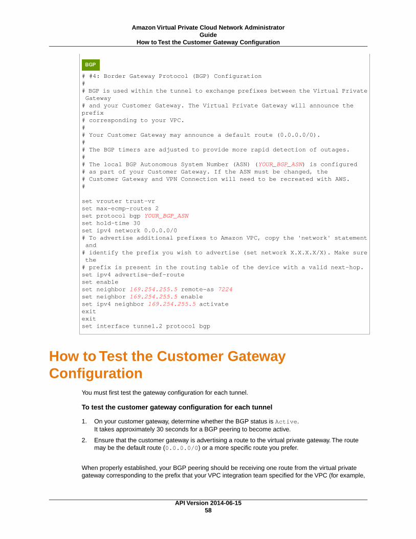
# #4: Border Gateway Protocol (BGP) Configuration## BGP is used within the tunnel to exchange prefixes between the Virtual Private Gateway# and your Customer Gateway. The Virtual Private Gateway will announce the prefix # corresponding to your VPC.## Your Customer Gateway may announce a default route (0.0.0.0/0).## The BGP timers are adjusted to provide more rapid detection of outages.## The local BGP Autonomous System Number (ASN) (YOUR_BGP_ASN) is configured# as part of your Customer Gateway. If the ASN must be changed, the# Customer Gateway and VPN Connection will need to be recreated with AWS.#
set vrouter trust-vrset max-ecmp-routes 2set protocol bgp YOUR_BGP_ASNset hold-time 30set ipv4 network 0.0.0.0/0# To advertise additional prefixes to Amazon VPC, copy the 'network' statement and # identify the prefix you wish to advertise (set network X.X.X.X/X). Make sure the # prefix is present in the routing table of the device with a valid next-hop. set ipv4 advertise-def-routeset enableset neighbor 169.254.255.5 remote-as 7224set neighbor 169.254.255.5 enableset ipv4 neighbor 169.254.255.5 activateexitexitset interface tunnel.2 protocol bgp
How to Test the Customer GatewayConfiguration
You must first test the gateway configuration for each tunnel.
To test the customer gateway configuration for each tunnel
1. On your customer gateway, determine whether the BGP status is Active.It takes approximately 30 seconds for a BGP peering to become active.
2. Ensure that the customer gateway is advertising a route to the virtual private gateway. The routemay be the default route (0.0.0.0/0) or a more specific route you prefer.
When properly established, your BGP peering should be receiving one route from the virtual privategateway corresponding to the prefix that your VPC integration team specified for the VPC (for example,
API Version 2014-06-1558
Amazon Virtual Private Cloud Network AdministratorGuide
How to Test the Customer Gateway Configuration

10.0.0.0/24). If the BGP peering is established, you are receiving a prefix, and you are advertising aprefix, your tunnel is configured correctly. Make sure that both tunnels are in this state.
Next you must test the connectivity for each tunnel.
ImportantFor the connectivity test to work, you must configure any security group or network ACL in yourVPC that filters traffic to the instance to allow inbound and outbound ICMP traffic.
To test the end-to-end connectivity of each tunnel
1. Launch an instance of one of the Amazon Linux AMIs into your VPC. The Amazon Linux AMIs arelisted in the launch wizard when you launch an instance from the AWS Management Console. Formore information, see the Amazon Virtual Private Cloud Getting Started Guide.
2. After the instance is running, get its private IP address (for example, 10.0.0.4).The console displaysthe address as part of the instance's details.
3. On a system in your home network, use the ping command with the instance's IP address. Makesure that the computer you ping from is behind the customer gateway. A successful response shouldbe similar to the following.
PROMPT> ping 10.0.0.4Pinging 10.0.0.4 with 32 bytes of data:
Reply from 10.0.0.4: bytes=32 time<1ms TTL=128Reply from 10.0.0.4: bytes=32 time<1ms TTL=128Reply from 10.0.0.4: bytes=32 time<1ms TTL=128
Ping statistics for 10.0.0.4:Packets: Sent = 3, Received = 3, Lost = 0 (0% loss),
Approximate round trip times in milliseconds:Minimum = 0ms, Maximum = 0ms, Average = 0ms
NoteIf you ping an instance from your customer gateway router, ensure that you are sourcing pingmessages from an internal IP address, not a tunnel IP address. Some AMIs don't respond toping messages from tunnel IP addresses.
If your tunnels don't test successfully, see Troubleshooting Juniper ScreenOS Customer GatewayConnectivity (p. 100).
API Version 2014-06-1559
Amazon Virtual Private Cloud Network AdministratorGuide
How to Test the Customer Gateway Configuration
Example:Yamaha Device
Topics
• A High-Level View of the Customer Gateway (p. 61)
• A Detailed View of the Customer Gateway and an Example Configuration (p. 61)
• How to Test the Customer Gateway Configuration (p. 67)
In this section we walk you through an example of the configuration information provided by your integrationteam if your customer gateway is a Yamaha RT107e, RTX1200, RTX1500, RTX3000, or SRT100 router.
Two diagrams illustrate the example configuration. The first diagram shows the high-level layout of thecustomer gateway, and the second diagram shows the details of the example configuration.You shoulduse the real configuration information that you receive from your integration team and apply it to yourcustomer gateway.
API Version 2014-06-1560
Amazon Virtual Private Cloud Network AdministratorGuide

A High-Level View of the Customer GatewayThe following diagram shows the general details of your customer gateway. Note that the VPN connectionconsists of two separate tunnels. Using redundant tunnels ensures continuous availability in the casethat a device fails.
A Detailed View of the Customer Gateway andan Example Configuration
The diagram in this section illustrates an example Yamaha customer gateway. Following the diagram,there is a corresponding example of the configuration information your integration team should provide.The example configuration contains a set of information for each of the tunnels that you must configure.
In addition, the example configuration refers to these items that you must provide:
• YOUR_UPLINK_ADDRESS—The IP address for the Internet-routable external interface on the customergateway (which must be static, and can't be behind a device performing NAT)
• YOUR_LOCAL_NETWORK_ADDRESS—The IP address that is assigned to the LAN interface connectedto your local network (most likely a private address such as 192.168.0.1)
• YOUR_BGP_ASN—The customer gateway's BGP ASN (we use 65000 by default)
The example configuration includes several example values to help you understand how configurationworks. For example, we provide example values for the VPN connection ID (vpn-44a8938f), virtual privategateway ID (vgw-8db04f81), the IP addresses (72.21.209.*, 169.254.255.*), and the remote ASN (7224).
API Version 2014-06-1561
Amazon Virtual Private Cloud Network AdministratorGuide
A High-Level View of the Customer Gateway

You'll replace these example values with the actual values from the configuration information that youreceive.
In addition, you must also:
• Configure the outside interface (referred to as LAN3 in the example configuration).
• Configure the tunnel interface IDs (referred to as Tunnel #1 and Tunnel #2 in the exampleconfiguration).
• Configure all internal routing that moves traffic between the customer gateway and your local network.
In the following diagram and example configuration, you must replace the items in red italics with valuesthat apply to your particular configuration.
WarningThe following configuration information is an example of what you can expect your integrationteam to provide. Many of the values in the following example will be different from the actualconfiguration information that you receive.You must use the actual values and not the examplevalues shown here, or your implementation will fail.
# Amazon Web Services # Virtual Private Cloud
# AWS utilizes unique identifiers to manage the configuration of # a VPN Connection. Each VPN Connection is assigned an identifier and is # associated with two other identifiers, namely the # Customer Gateway Identifier and Virtual Private Gateway Identifier. # # Your VPN Connection ID : vpn-44a8938f# Your Virtual Private Gateway ID : vgw-8db04f81# Your Customer Gateway ID : cgw-b4dc3961# #
API Version 2014-06-1562
Amazon Virtual Private Cloud Network AdministratorGuide
A Detailed View of the Customer Gateway and anExample Configuration

# This configuration consists of two tunnels. Both tunnels must be # configured on your Customer Gateway. # # -------------------------------------------------------------------------------- # IPsec Tunnel #1 # --------------------------------------------------------------------------------
# #1: Internet Key Exchange (IKE) Configuration # # A policy is established for the supported ISAKMP encryption, # authentication, Diffie-Hellman, lifetime, and key parameters. # tunnel select 1 ipsec ike encryption 1 aes-cbc ipsec ike group 1 modp1024 ipsec ike hash 1 sha
# The ISAKMP keyring stores the Pre Shared Key used to authenticate the # tunnel endpoints. # ipsec ike pre-shared-key 1 text plain-text-password1
# #2: IPsec Configuration
# The IPsec policy defines the encryption, authentication, and IPsec # mode parameters.
# Note that there is a global list of IPsec policies, each identified by # sequence number. This policy is defined as #200, which may conflict with # an existing policy using the same number. If so, we recommend changing # the sequence number to avoid conflicts. #
ipsec tunnel 200 ipsec sa policy 200 1 esp aes-cbc sha-hmac
# The IPsec profile references the IPsec policy and further defines # the Diffie-Hellman group and security association lifetime.
ipsec ike duration ipsec-sa 1 3600 ipsec ike pfs 1 on
# Additional parameters of the IPsec configuration are set here. Note that # these parameters are global and therefore impact other IPsec # associations. # This option instructs the router to clear the "Don't Fragment" # bit from packets that carry this bit and yet must be fragmented, enabling # them to be fragmented. # ipsec tunnel outer df-bit clear
API Version 2014-06-1563
Amazon Virtual Private Cloud Network AdministratorGuide
A Detailed View of the Customer Gateway and anExample Configuration

# This option enables IPsec Dead Peer Detection, which causes periodic # messages to be sent to ensure a Security Association remains operational.
ipsec ike keepalive use 1 on dpd 10 3
# -------------------------------------------------------------------------------- # #3: Tunnel Interface Configuration # # A tunnel interface is configured to be the logical interface associated # with the tunnel. All traffic routed to the tunnel interface will be # encrypted and transmitted to the VPC. Similarly, traffic from the VPC # will be logically received on this interface. # # # The address of the interface is configured with the setup for your # Customer Gateway. If the address changes, the Customer Gateway and VPN # Connection must be recreated with Amazon VPC. # ipsec ike local address 1 YOUR_LOCAL_NETWORK_ADDRESSipsec ike remote address 1 72.21.209.225ip tunnel address 169.254.255.2/30 ip tunnel remote address 169.254.255.1
# This option causes the router to reduce the Maximum Segment Size of # TCP packets to prevent packet fragmentation
ip tunnel tcp mss limit 1396 tunnel enable 1 no tunnel select 1 ipsec auto refresh on
# -------------------------------------------------------------------------------- # #4: Border Gateway Protocol (BGP) Configuration #
# BGP is used within the tunnel to exchange prefixes between the # Virtual Private Gateway and your Customer Gateway. The Virtual Private Gateway
# will announce the prefix corresponding to your VPC. # # The BGP timers are adjusted to provide more rapid detection of outages. # # The local BGP Autonomous System Number (ASN) (YOUR_BGP_ASN) is configured # as part of your Customer Gateway. If the ASN must be changed, the # Customer Gateway and VPN Connection will need to be recreated with AWS. # bgp use onbgp autonomous-system YOUR_BGP_ASNbgp neighbor 1 7224 169.254.255.1 hold-time=30 local-address=169.254.255.2
API Version 2014-06-1564
Amazon Virtual Private Cloud Network AdministratorGuide
A Detailed View of the Customer Gateway and anExample Configuration

# To advertise additional prefixes to Amazon VPC, copy the statement and # identify the prefix you wish to advertise. Make sure the # prefix is present in the routing table of the device with a valid next-hop.
bgp import filter 1 equal 0.0.0.0/0bgp import 7224 static filter 1bgp configure refresh
# -------------------------------------------------------------------------------- # IPsec Tunnel #2 # --------------------------------------------------------------------------------
# #1: Internet Key Exchange (IKE) Configuration # # A policy is established for the supported ISAKMP encryption, # authentication, Diffie-Hellman, lifetime, and key parameters. # tunnel select 2 ipsec ike encryption 2 aes-cbc ipsec ike group 2 modp1024 ipsec ike hash 2 sha
# The ISAKMP keyring stores the Pre Shared Key used to authenticate the # tunnel endpoints. # ipsec ike pre-shared-key 2 text plain-text-password2
# #2: IPsec Configuration
# The IPsec policy defines the encryption, authentication, and IPsec # mode parameters.
# Note that there are a global list of IPsec policies, each identified by # sequence number. This policy is defined as #201, which may conflict with # an existing policy using the same number. If so, we recommend changing # the sequence number to avoid conflicts. #
ipsec tunnel 201ipsec sa policy 201 2 esp aes-cbc sha-hmac
# The IPsec profile references the IPsec policy and further defines # the Diffie-Hellman group and security association lifetime.
ipsec ike duration ipsec-sa 2 3600ipsec ike pfs 2 on
# Additional parameters of the IPsec configuration are set here. Note that
API Version 2014-06-1565
Amazon Virtual Private Cloud Network AdministratorGuide
A Detailed View of the Customer Gateway and anExample Configuration

# these parameters are global and therefore impact other IPsec # associations. # This option instructs the router to clear the "Don't Fragment" # bit from packets that carry this bit and yet must be fragmented, enabling # them to be fragmented. # ipsec tunnel outer df-bit clear
# This option enables IPsec Dead Peer Detection, which causes periodic # messages to be sent to ensure a Security Association remains operational.
ipsec ike keepalive
# -------------------------------------------------------------------------------- # #3: Tunnel Interface Configuration # # A tunnel interface is configured to be the logical interface associated # with the tunnel. All traffic routed to the tunnel interface will be # encrypted and transmitted to the VPC. Similarly, traffic from the VPC # will be logically received on this interface. # # Association with the IPsec security association is done through the # "tunnel protection" command. # # The address of the interface is configured with the setup for your # Customer Gateway. If the address changes, the Customer Gateway and VPN # Connection must be recreated with Amazon VPC. # ipsec ike local address 2 YOUR_LOCAL_NETWORK_ADDRESSipsec ike remote address 2 72.21.209.193ip tunnel address 169.254.255.6/30 ip tunnel remote address 169.254.255.5
# This option causes the router to reduce the Maximum Segment Size of # TCP packets to prevent packet fragmentation
ip tunnel tcp mss limit 1396 tunnel enable 2 no tunnel select 2 ipsec auto refresh on
# -------------------------------------------------------------------------------- # #4: Border Gateway Protocol (BGP) Configuration #
# BGP is used within the tunnel to exchange prefixes between the # Virtual Private Gateway and your Customer Gateway. The Virtual Private Gateway
# will announce the prefix corresponding to your VPC. #
API Version 2014-06-1566
Amazon Virtual Private Cloud Network AdministratorGuide
A Detailed View of the Customer Gateway and anExample Configuration

# The BGP timers are adjusted to provide more rapid detection of outages. # # The local BGP Autonomous System Number (ASN) (YOUR_BGP_ASN) is configured # as part of your Customer Gateway. If the ASN must be changed, the # Customer Gateway and VPN Connection will need to be recreated with AWS. # bgp use onbgp autonomous-system YOUR_BGP_ASNbgp neighbor 1 7224 169.254.255.5 hold-time=30 local-address=169.254.255.6
# To advertise additional prefixes to Amazon VPC, copy the statement and # identify the prefix you wish to advertise. Make sure the # prefix is present in the routing table of the device with a valid next-hop.
bgp import filter 1 equal 0.0.0.0/0bgp import 7224 static filter 1bgp configure refresh
How to Test the Customer GatewayConfiguration
You must first test the gateway configuration for each tunnel.
To test the customer gateway configuration for each tunnel
1. On your customer gateway, determine whether the BGP status is Active.It takes approximately 30 seconds for a BGP peering to become active.
2. Ensure that the customer gateway is advertising a route to the virtual private gateway. The routemay be the default route (0.0.0.0/0) or a more specific route you prefer.
When properly established, your BGP peering should be receiving one route from the virtual privategateway corresponding to the prefix that your VPC integration team specified for the VPC (for example,10.0.0.0/24). If the BGP peering is established, you are receiving a prefix, and you are advertising aprefix, your tunnel is configured correctly. Make sure that both tunnels are in this state.
Next you must test the connectivity for each tunnel.
ImportantFor the connectivity test to work, you must configure any security group or network ACL in yourVPC that filters traffic to the instance to allow inbound and outbound ICMP traffic.
To test the end-to-end connectivity of each tunnel
1. Launch an instance of one of the Amazon Linux AMIs into your VPC. The Amazon Linux AMIs arelisted in the launch wizard when you launch an instance from the AWS Management Console. Formore information, see the Amazon Virtual Private Cloud Getting Started Guide.
2. After the instance is running, get its private IP address (for example, 10.0.0.4).The console displaysthe address as part of the instance's details.
3. On a system in your home network, use the ping command with the instance's IP address. Makesure that the computer you ping from is behind the customer gateway. A successful response shouldbe similar to the following.
API Version 2014-06-1567
Amazon Virtual Private Cloud Network AdministratorGuide
How to Test the Customer Gateway Configuration

PROMPT> ping 10.0.0.4Pinging 10.0.0.4 with 32 bytes of data:
Reply from 10.0.0.4: bytes=32 time<1ms TTL=128Reply from 10.0.0.4: bytes=32 time<1ms TTL=128Reply from 10.0.0.4: bytes=32 time<1ms TTL=128
Ping statistics for 10.0.0.4:Packets: Sent = 3, Received = 3, Lost = 0 (0% loss),
Approximate round trip times in milliseconds:Minimum = 0ms, Maximum = 0ms, Average = 0ms
NoteIf you ping an instance from your customer gateway router, ensure that you are sourcing pingmessages from an internal IP address, not a tunnel IP address. Some AMIs don't respond toping messages from tunnel IP addresses.
If your tunnels don't test successfully, see Troubleshooting Yamaha Customer GatewayConnectivity (p. 103).
API Version 2014-06-1568
Amazon Virtual Private Cloud Network AdministratorGuide
How to Test the Customer Gateway Configuration

Example: Generic CustomerGateway Using Border GatewayProtocol
Topics
• A High-Level View of the Customer Gateway (p. 70)
• A Detailed View of the Customer Gateway and an Example Configuration (p. 70)
• How to Test the Customer Gateway Configuration (p. 75)
If your customer gateway isn't one of the types discussed earlier in this guide, your integration team willprovide you with generic information that you can use to configure your customer gateway. This sectioncontains an example of that information.
Two diagrams illustrate the example configuration. The first diagram shows the high-level layout of thecustomer gateway, and the second diagram shows details from the example configuration.You shoulduse the real configuration information that you receive from your integration team and apply it to yourcustomer gateway.
API Version 2014-06-1569
Amazon Virtual Private Cloud Network AdministratorGuide
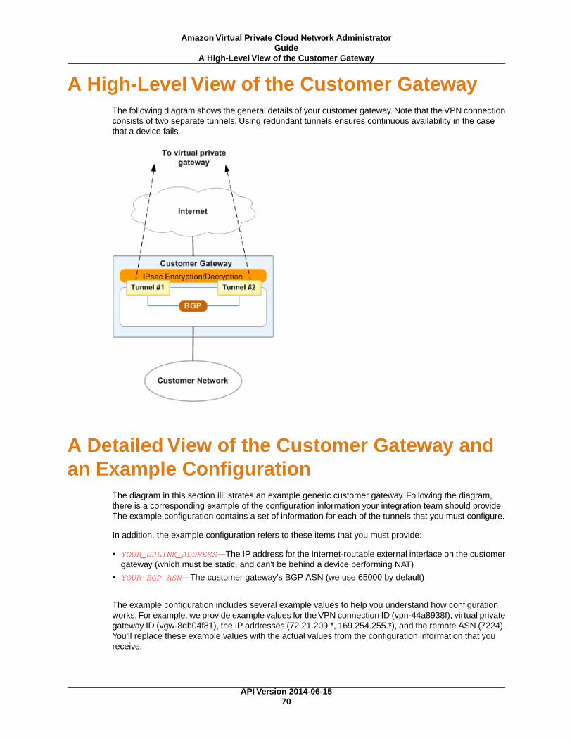
A High-Level View of the Customer GatewayThe following diagram shows the general details of your customer gateway. Note that the VPN connectionconsists of two separate tunnels. Using redundant tunnels ensures continuous availability in the casethat a device fails.
A Detailed View of the Customer Gateway andan Example Configuration
The diagram in this section illustrates an example generic customer gateway. Following the diagram,there is a corresponding example of the configuration information your integration team should provide.The example configuration contains a set of information for each of the tunnels that you must configure.
In addition, the example configuration refers to these items that you must provide:
• YOUR_UPLINK_ADDRESS—The IP address for the Internet-routable external interface on the customergateway (which must be static, and can't be behind a device performing NAT)
• YOUR_BGP_ASN—The customer gateway's BGP ASN (we use 65000 by default)
The example configuration includes several example values to help you understand how configurationworks. For example, we provide example values for the VPN connection ID (vpn-44a8938f), virtual privategateway ID (vgw-8db04f81), the IP addresses (72.21.209.*, 169.254.255.*), and the remote ASN (7224).You'll replace these example values with the actual values from the configuration information that youreceive.
API Version 2014-06-1570
Amazon Virtual Private Cloud Network AdministratorGuide
A High-Level View of the Customer Gateway

In the following diagram and example configuration, you must replace the items in red italics with valuesthat apply to your particular configuration.
Amazon Web ServicesVirtual Private Cloud
VPN Connection Configuration===============================================AWS utilizes unique identifiers to manipulate the configuration of a VPN Connection. Each VPN Connection is assigned a VPN identifier and is associated with two other identifiers, namely the Customer Gateway Identifier and the Virtual Private Gateway Identifier.
Your VPN Connection ID : vpn-44a8938fYour Virtual Private Gateway ID : vgw-8db04f81Your Customer Gateway ID : cgw-b4dc3961
A VPN Connection consists of a pair of IPsec tunnel security associations (SAs).
It is important that both tunnel security associations be configured.
IPsec Tunnel #1================================================
#1: Internet Key Exchange Configuration
Configure the IKE SA as follows- Authentication Method : Pre-Shared Key - Pre-Shared Key : plain-text-password1- Authentication Algorithm : sha1- Encryption Algorithm : aes-128-cbc
API Version 2014-06-1571
Amazon Virtual Private Cloud Network AdministratorGuide
A Detailed View of the Customer Gateway and anExample Configuration
- Lifetime : 28800 seconds- Phase 1 Negotiation Mode : main- Perfect Forward Secrecy : Diffie-Hellman Group 2
#2: IPsec Configuration
Configure the IPsec SA as follows:- Protocol : esp- Authentication Algorithm : hmac-sha1-96- Encryption Algorithm : aes-128-cbc- Lifetime : 3600 seconds- Mode : tunnel- Perfect Forward Secrecy : Diffie-Hellman Group 2
IPsec Dead Peer Detection (DPD) will be enabled on the AWS Endpoint. Werecommend configuring DPD on your endpoint as follows:- DPD Interval : 10- DPD Retries : 3
IPsec ESP (Encapsulating Security Payload) inserts additionalheaders to transmit packets. These headers require additional space, which reduces the amount of space available to transmit application data.To limit the impact of this behavior, we recommend the following configuration on your Customer Gateway:- TCP MSS Adjustment : 1396 bytes- Clear Don't Fragment Bit : enabled- Fragmentation : Before encryption
#3: Tunnel Interface Configuration
Your Customer Gateway must be configured with a tunnel interface that isassociated with the IPsec tunnel. All traffic transmitted to the tunnelinterface is encrypted and transmitted to the Virtual Private Gateway.
Additionally, the Virtual Private Gateway and Customer Gateway establish the BGPpeering from your tunnel interface.
The Customer Gateway and Virtual Private Gateway each have two addresses that relateto this IPsec tunnel. Each contains an outside address, upon which encryptedtraffic is exchanged. Each also contain an inside address associated withthe tunnel interface.
The Customer Gateway outside IP address was provided when the Customer Gatewaywas created. Changing the IP address requires the creation of a newCustomer Gateway.
The Customer Gateway inside IP address should be configured on your tunnelinterface.
Outside IP Addresses:- Customer Gateway: : YOUR_UPLINK_ADDRESS- Virtual Private Gateway : 72.21.209.193
API Version 2014-06-1572
Amazon Virtual Private Cloud Network AdministratorGuide
A Detailed View of the Customer Gateway and anExample Configuration

Inside IP Addresses- Customer Gateway : 169.254.255.6/30- Virtual Private Gateway : 169.254.255.5/30
Configure your tunnel to fragment at the optimal size:- Tunnel interface MTU : 1436 bytes
#4: Border Gateway Protocol (BGP) Configuration:
The Border Gateway Protocol (BGPv4) is used within the tunnel, between the insideIP addresses, to exchange routes from the VPC to your home network. EachBGP router has an Autonomous System Number (ASN). Your ASN was provided to AWS when the Customer Gateway was created.
BGP Configuration Options:- Customer Gateway ASN : YOUR_BGP_ASN- Virtual Private Gateway ASN : 7224- Neighbor IP Address : 169.254.255.1- Neighbor Hold Time : 30
Configure BGP to announce the default route (0.0.0.0/0) to the VPN ConnectionGateway. The Virtual Private Gateway will announce prefixes to your Customer Gateway based upon the prefixes assigned in the creation of the VPC.
IPsec Tunnel #2=====================================================
#1: Internet Key Exchange Configuration
Configure the IKE SA as follows- Authentication Method : Pre-Shared Key - Pre-Shared Key : plain-text-password2- Authentication Algorithm : sha1- Encryption Algorithm : aes-128-cbc- Lifetime : 28800 seconds- Phase 1 Negotiation Mode : main- Perfect Forward Secrecy : Diffie-Hellman Group 2
#2: IPsec Configuration
Configure the IPsec SA as follows:- Protocol : esp- Authentication Algorithm : hmac-sha1-96- Encryption Algorithm : aes-128-cbc- Lifetime : 3600 seconds- Mode : tunnel- Perfect Forward Secrecy : Diffie-Hellman Group 2
IPsec Dead Peer Detection (DPD) will be enabled on the AWS Endpoint. Werecommend configuring DPD on your endpoint as follows:- DPD Interval : 10- DPD Retries : 3
API Version 2014-06-1573
Amazon Virtual Private Cloud Network AdministratorGuide
A Detailed View of the Customer Gateway and anExample Configuration

IPsec ESP (Encapsulating Security Payload) inserts additionalheaders to transmit packets. These headers require additional space, which reduces the amount of space available to transmit application data.To limit the impact of this behavior, we recommend the following configuration on your Customer Gateway:- TCP MSS Adjustment : 1396 bytes- Clear Don't Fragment Bit : enabled- Fragmentation : Before encryption
#3: Tunnel Interface Configuration
Your Customer Gateway must be configured with a tunnel interface that isassociated with the IPsec tunnel. All traffic transmitted to the tunnelinterface is encrypted and transmitted to the Virtual Private Gateway.
Additionally, the Virtual Private Gateway and Customer Gateway establish the BGPpeering from your tunnel interface.
The Customer Gateway and Virtual Private Gateway each have two addresses that relateto this IPsec tunnel. Each contains an outside address, upon which encryptedtraffic is exchanged. Each also contain an inside address associated withthe tunnel interface.
The Customer Gateway outside IP address was provided when the Customer Gatewaywas created. Changing the IP address requires the creation of a newCustomer Gateway.
The Customer Gateway inside IP address should be configured on your tunnelinterface.
Outside IP Addresses:- Customer Gateway: : YOUR_UPLINK_ADDRESS- Virtual Private Gateway : 72.21.209.193
Inside IP Addresses- Customer Gateway : 169.254.255.6/30- Virtual Private Gateway : 169.254.255.5/30
Configure your tunnel to fragment at the optimal size:- Tunnel interface MTU : 1436 bytes
#4: Border Gateway Protocol (BGP) Configuration:
The Border Gateway Protocol (BGPv4) is used within the tunnel, between the insideIP addresses, to exchange routes from the VPC to your home network. EachBGP router has an Autonomous System Number (ASN). Your ASN was provided to AWS when the Customer Gateway was created.
BGP Configuration Options:- Customer Gateway ASN : YOUR_BGP_ASN- Virtual Private Gateway ASN : 7224
API Version 2014-06-1574
Amazon Virtual Private Cloud Network AdministratorGuide
A Detailed View of the Customer Gateway and anExample Configuration

- Neighbor IP Address : 169.254.255.5- Neighbor Hold Time : 30
Configure BGP to announce the default route (0.0.0.0/0) to the VPN ConnectionGateway. The Virtual Private Gateway will announce prefixes to your Customer Gateway based upon the prefixes assigned in the creation of the VPC.
How to Test the Customer GatewayConfiguration
You must first test the gateway configuration for each tunnel.
To test the customer gateway configuration for each tunnel
1. On your customer gateway, determine whether the BGP status is Active.It takes approximately 30 seconds for a BGP peering to become active.
2. Ensure that the customer gateway is advertising a route to the virtual private gateway. The routemay be the default route (0.0.0.0/0) or a more specific route you prefer.
When properly established, your BGP peering should be receiving one route from the virtual privategateway corresponding to the prefix that your VPC integration team specified for the VPC (for example,10.0.0.0/24). If the BGP peering is established, you are receiving a prefix, and you are advertising aprefix, your tunnel is configured correctly. Make sure that both tunnels are in this state.
Next you must test the connectivity for each tunnel.
ImportantFor the connectivity test to work, you must configure any security group or network ACL in yourVPC that filters traffic to the instance to allow inbound and outbound ICMP traffic.
To test the end-to-end connectivity of each tunnel
1. Launch an instance of one of the Amazon Linux AMIs into your VPC. The Amazon Linux AMIs arelisted in the launch wizard when you launch an instance from the AWS Management Console. Formore information, see the Amazon Virtual Private Cloud Getting Started Guide.
2. After the instance is running, get its private IP address (for example, 10.0.0.4).The console displaysthe address as part of the instance's details.
3. On a system in your home network, use the ping command with the instance's IP address. Makesure that the computer you ping from is behind the customer gateway. A successful response shouldbe similar to the following.
PROMPT> ping 10.0.0.4Pinging 10.0.0.4 with 32 bytes of data:
Reply from 10.0.0.4: bytes=32 time<1ms TTL=128Reply from 10.0.0.4: bytes=32 time<1ms TTL=128Reply from 10.0.0.4: bytes=32 time<1ms TTL=128
Ping statistics for 10.0.0.4:Packets: Sent = 3, Received = 3, Lost = 0 (0% loss),
API Version 2014-06-1575
Amazon Virtual Private Cloud Network AdministratorGuide
How to Test the Customer Gateway Configuration

Approximate round trip times in milliseconds:Minimum = 0ms, Maximum = 0ms, Average = 0ms
NoteIf you ping an instance from your customer gateway router, ensure that you are sourcing pingmessages from an internal IP address, not a tunnel IP address. Some AMIs don't respond toping messages from tunnel IP addresses.
If your tunnels don't test successfully, see Troubleshooting Generic Device Customer Gateway ConnectivityUsing Border Gateway Protocol (p. 106).
API Version 2014-06-1576
Amazon Virtual Private Cloud Network AdministratorGuide
How to Test the Customer Gateway Configuration

Example: Generic CustomerGateway without Border GatewayProtocol
Topics
• A High-Level View of the Customer Gateway (p. 78)
• A Detailed View of the Customer Gateway and an Example Configuration (p. 78)
• How to Test the Customer Gateway Configuration (p. 83)
If your customer gateway isn't one of the types discussed earlier in this guide, your integration team willprovide you with generic information that you can use to configure your customer gateway. This sectioncontains an example of that information.
Two diagrams illustrate the example configuration. The first diagram shows the high-level layout of thecustomer gateway, and the second diagram shows details from the example configuration.You shoulduse the real configuration information that you receive from your integration team and apply it to yourcustomer gateway.
API Version 2014-06-1577
Amazon Virtual Private Cloud Network AdministratorGuide
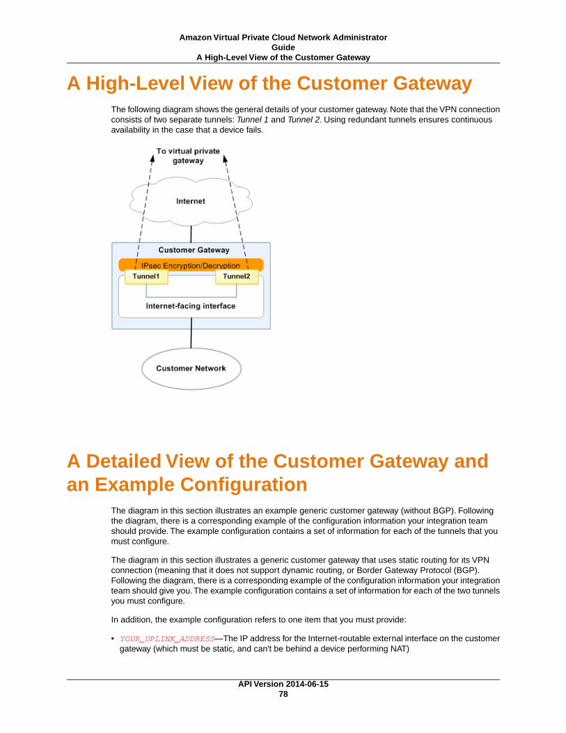
A High-Level View of the Customer GatewayThe following diagram shows the general details of your customer gateway. Note that the VPN connectionconsists of two separate tunnels: Tunnel 1 and Tunnel 2. Using redundant tunnels ensures continuousavailability in the case that a device fails.
A Detailed View of the Customer Gateway andan Example Configuration
The diagram in this section illustrates an example generic customer gateway (without BGP). Followingthe diagram, there is a corresponding example of the configuration information your integration teamshould provide. The example configuration contains a set of information for each of the tunnels that youmust configure.
The diagram in this section illustrates a generic customer gateway that uses static routing for its VPNconnection (meaning that it does not support dynamic routing, or Border Gateway Protocol (BGP).Following the diagram, there is a corresponding example of the configuration information your integrationteam should give you.The example configuration contains a set of information for each of the two tunnelsyou must configure.
In addition, the example configuration refers to one item that you must provide:
• YOUR_UPLINK_ADDRESS—The IP address for the Internet-routable external interface on the customergateway (which must be static, and can't be behind a device performing NAT)
API Version 2014-06-1578
Amazon Virtual Private Cloud Network AdministratorGuide
A High-Level View of the Customer Gateway

The example configuration includes several example values to help you understand how configurationworks. For example, we provide example values for the VPN connection ID (vpn-44a8938f), virtual privategateway ID (vgw-8db04f81), and the VGW IP addresses (72.21.209.*, 169.254.255.*).You'll replacethese example values with the actual values from the configuration information that you receive.
In the following diagram and example configuration, you must replace the items in red italics with valuesthat apply to your particular configuration.
ImportantThe following configuration information is an example of what you can expect an integrationteam to provide . Many of the values in the following example will be different from the actualconfiguration information that you receive.You must use the actual values and not the examplevalues shown here, or your implementation will fail.
Amazon Web ServicesVirtual Private Cloud
VPN Connection Configuration================================================================================AWS utilizes unique identifiers to manipulate the configuration ofa VPN Connection. Each VPN Connection is assigned a VPN Connection Identifierand is associated with two other identifiers, namely theCustomer Gateway Identifier and the Virtual Private Gateway Identifier.
Your VPN Connection ID : vpn-44a8938fYour Virtual Private Gateway ID : vgw-8db04f81Your Customer Gateway ID : cgw-ff628496
A VPN Connection consists of a pair of IPSec tunnel security associations (SAs).It is important that both tunnel security associations be configured.
IPSec Tunnel #1
API Version 2014-06-1579
Amazon Virtual Private Cloud Network AdministratorGuide
A Detailed View of the Customer Gateway and anExample Configuration

================================================================================
#1: Internet Key Exchange Configuration
Configure the IKE SA as follows - Authentication Method : Pre-Shared Key - Pre-Shared Key : PRE-SHARED-KEY-IN-PLAIN-TEXT - Authentication Algorithm : sha1 - Encryption Algorithm : aes-128-cbc - Lifetime : 28800 seconds - Phase 1 Negotiation Mode : main - Perfect Forward Secrecy : Diffie-Hellman Group 2
#2: IPSec Configuration
Configure the IPSec SA as follows: - Protocol : esp - Authentication Algorithm : hmac-sha1-96 - Encryption Algorithm : aes-128-cbc - Lifetime : 3600 seconds - Mode : tunnel - Perfect Forward Secrecy : Diffie-Hellman Group 2
IPSec Dead Peer Detection (DPD) will be enabled on the AWS Endpoint. Werecommend configuring DPD on your endpoint as follows: - DPD Interval : 10 - DPD Retries : 3
IPSec ESP (Encapsulating Security Payload) inserts additionalheaders to transmit packets. These headers require additional space,which reduces the amount of space available to transmit application data.To limit the impact of this behavior, we recommend the followingconfiguration on your Customer Gateway: - TCP MSS Adjustment : 1387 bytes - Clear Don't Fragment Bit : enabled - Fragmentation : Before encryption
#3: Tunnel Interface Configuration
Your Customer Gateway must be configured with a tunnel interface that isassociated with the IPSec tunnel. All traffic transmitted to the tunnelinterface is encrypted and transmitted to the Virtual Private Gateway.
The Customer Gateway and Virtual Private Gateway each have two addresses that relateto this IPSec tunnel. Each contains an outside address, upon which encryptedtraffic is exchanged. Each also contain an inside address associated withthe tunnel interface.
The Customer Gateway outside IP address was provided when the Customer Gatewaywas created. Changing the IP address requires the creation of a newCustomer Gateway.
API Version 2014-06-1580
Amazon Virtual Private Cloud Network AdministratorGuide
A Detailed View of the Customer Gateway and anExample Configuration

The Customer Gateway inside IP address should be configured on your tunnelinterface.
Outside IP Addresses: - Customer Gateway : YOUR_UPLINK_ADDRESS - Virtual Private Gateway : 72.21.209.193
Inside IP Addresses - Customer Gateway : 169.254.255.74/30 - Virtual Private Gateway : 169.254.255.73/30
Configure your tunnel to fragment at the optimal size: - Tunnel interface MTU : 1427 bytes
#4: Static Routing Configuration:
To route traffic between your internal network and your VPC,you will need a static route added to your router.
Static Route Configuration Options:
- Next hop : 169.254.255.73
You should add static routes towards your internal network on the VGW.The VGW will then send traffic towards your internal network overthe tunnels.
IPSec Tunnel #2 ================================================================================
#1: Internet Key Exchange Configuration
Configure the IKE SA as follows - Authentication Method : Pre-Shared Key - Pre-Shared Key : PRE-SHARED-KEY-IN-PLAIN-TEXT - Authentication Algorithm : sha1 - Encryption Algorithm : aes-128-cbc - Lifetime : 28800 seconds - Phase 1 Negotiation Mode : main - Perfect Forward Secrecy : Diffie-Hellman Group 2
#2: IPSec Configuration
Configure the IPSec SA as follows: - Protocol : esp - Authentication Algorithm : hmac-sha1-96 - Encryption Algorithm : aes-128-cbc - Lifetime : 3600 seconds - Mode : tunnel - Perfect Forward Secrecy : Diffie-Hellman Group 2
IPSec Dead Peer Detection (DPD) will be enabled on the AWS Endpoint. Werecommend configuring DPD on your endpoint as follows:
API Version 2014-06-1581
Amazon Virtual Private Cloud Network AdministratorGuide
A Detailed View of the Customer Gateway and anExample Configuration

- DPD Interval : 10 - DPD Retries : 3
IPSec ESP (Encapsulating Security Payload) inserts additionalheaders to transmit packets. These headers require additional space,which reduces the amount of space available to transmit application data.To limit the impact of this behavior, we recommend the followingconfiguration on your Customer Gateway: - TCP MSS Adjustment : 1387 bytes - Clear Don't Fragment Bit : enabled - Fragmentation : Before encryption
#3: Tunnel Interface Configuration
Your Customer Gateway must be configured with a tunnel interface that isassociated with the IPSec tunnel. All traffic transmitted to the tunnelinterface is encrypted and transmitted to the Virtual Private Gateway.
The Customer Gateway and Virtual Private Gateway each have two addresses that relateto this IPSec tunnel. Each contains an outside address, upon which encryptedtraffic is exchanged. Each also contain an inside address associated withthe tunnel interface.
The Customer Gateway outside IP address was provided when the Customer Gatewaywas created. Changing the IP address requires the creation of a newCustomer Gateway.
The Customer Gateway inside IP address should be configured on your tunnelinterface.
Outside IP Addresses: - Customer Gateway : YOUR_UPLINK_ADDRESS - Virtual Private Gateway : 72.21.209.225
Inside IP Addresses - Customer Gateway : 169.254.255.78/30 - Virtual Private Gateway : 169.254.255.77/30
Configure your tunnel to fragment at the optimal size: - Tunnel interface MTU : 1427 bytes
#4: Static Routing Configuration:
To route traffic between your internal network and your VPC,you will need a static route added to your router.
Static Route Configuration Options:
- Next hop : 169.254.255.77
You should add static routes towards your internal network on the VGW.The VGW will then send traffic towards your internal network overthe tunnels.
API Version 2014-06-1582
Amazon Virtual Private Cloud Network AdministratorGuide
A Detailed View of the Customer Gateway and anExample Configuration

How to Test the Customer GatewayConfiguration
You must first test the gateway configuration for each tunnel.
To test the customer gateway configuration for each tunnel
• On your customer gateway, verify that you have added a static route to the VPC CIDR IP space touse the tunnel interface.
Next you must test the connectivity for each tunnel.
ImportantFor the connectivity test to work, you must configure any security group or network ACL in yourVPC that filters traffic to the instance to allow inbound and outbound ICMP traffic.
To test the end-to-end connectivity of each tunnel
1. Launch an instance of one of the Amazon Linux AMIs into your VPC. The Amazon Linux AMIs areavailable in the Quick Start menu when you use the Launch Instances Wizard in the AWS ManagementConsole. For more information, see the Amazon Virtual Private Cloud Getting Started Guide.
2. After the instance is running, get its private IP address (for example, 10.0.0.4). The console displaysthe address as part of the instance's details.
3. On a system in your home network, use the ping command with the instance's IP address. Makesure that the computer you ping from is behind the customer gateway. A successful response shouldbe similar to the following.
PROMPT> ping 10.0.0.4Pinging 10.0.0.4 with 32 bytes of data:
Reply from 10.0.0.4: bytes=32 time<1ms TTL=128Reply from 10.0.0.4: bytes=32 time<1ms TTL=128Reply from 10.0.0.4: bytes=32 time<1ms TTL=128
Ping statistics for 10.0.0.4:Packets: Sent = 3, Received = 3, Lost = 0 (0% loss),
Approximate round trip times in milliseconds:Minimum = 0ms, Maximum = 0ms, Average = 0ms
NoteIf you ping an instance from your customer gateway router, ensure that you are sourcing pingmessages from an internal IP address, not a tunnel IP address. Some AMIs don't respond toping messages from tunnel IP addresses.
If your tunnels don't test successfully, see Troubleshooting Generic Device Customer Gateway ConnectivityUsing Border Gateway Protocol (p. 106).
API Version 2014-06-1583
Amazon Virtual Private Cloud Network AdministratorGuide
How to Test the Customer Gateway Configuration

Troubleshooting
The following topics contain troubleshooting information that you can use if your tunnels aren't in thecorrect state when you test your customer gateway.
Topics
• Troubleshooting Cisco ASA Customer Gateway Connectivity (p. 84)
• Troubleshooting Cisco IOS Customer Gateway Connectivity (p. 87)
• Troubleshooting Cisco IOS Customer Gateway without Border Gateway Protocol Connectivity (p. 92)
• Troubleshooting Juniper JunOS Customer Gateway Connectivity (p. 96)
• Troubleshooting Juniper ScreenOS Customer Gateway Connectivity (p. 100)
• Troubleshooting Yamaha Customer Gateway Connectivity (p. 103)
• Troubleshooting Generic Device Customer Gateway Connectivity Using Border GatewayProtocol (p. 106)
• Troubleshooting Generic Device Customer Gateway without Border Gateway ProtocolConnectivity (p. 108)
Troubleshooting Cisco ASA Customer GatewayConnectivity
When you troubleshoot the connectivity of a Cisco customer gateway, you need to consider three things:IKE, IPsec, and routing.You can troubleshoot these areas in any order, but we recommend that you startwith IKE (at the bottom of the network stack) and move up.
Please note that some Cisco ASAs only support Active/Standby mode.When you use these Cisco ASAs,you can have only one active tunnel at a time. The other standby tunnel becomes active if the first tunnelbecomes unavailable. With this redundancy, you should always have connectivity to your VPC throughone of the tunnels.
IKEUse the following command. The response shows a customer gateway with IKE configured correctly.
API Version 2014-06-1584
Amazon Virtual Private Cloud Network AdministratorGuide
Cisco ASA Customer Gateway Connectivity

ciscoasa# show crypto isakmp sa Active SA: 2 Rekey SA: 0 (A tunnel will report 1 Active and 1 Rekey SA during rekey)Total IKE SA: 2
1 IKE Peer: AWS_ENDPOINT_1 Type : L2L Role : initiator Rekey : no State : MM_ACTIVE
You should see one or more lines containing an src of the remote gateway specified in the tunnels. Thestate should be MM_ACTIVE and status should be ACTIVE. The absence of an entry, or any entry inanother state, indicates that IKE is not configured properly.
For further troubleshooting, run the following commands to enable log messages that provide diagnosticinformation.
router# term monrouter# debug crypto isakmp
To disable debugging, use the following command.
router# no debug crypto isakmp
IPsecUse the following command. The response shows a customer gateway with IPsec configured correctly.
ciscoasa# show crypto ipsec sainterface: outside Crypto map tag: VPN_crypto_map_name, seq num: 2, local addr: 172.25.50.101
access-list integ-ppe-loopback extended permit ip any vpc_subnet sub net_mask local ident (addr/mask/prot/port): (0.0.0.0/0.0.0.0/0/0) remote ident (addr/mask/prot/port): (vpc_subnet/subnet_mask/0/0) current_peer: integ-ppe1
#pkts encaps: 0, #pkts encrypt: 0, #pkts digest: 0 #pkts decaps: 0, #pkts decrypt: 0, #pkts verify: 0 #pkts compressed: 0, #pkts decompressed: 0 #pkts not compressed: 0, #pkts comp failed: 0, #pkts decomp failed: 0 #pre-frag successes: 0, #pre-frag failures: 0, #fragments created: 0 #PMTUs sent: 0, #PMTUs rcvd: 0, #decapsulated frgs needing reassembly: 0
#send errors: 0, #recv errors: 0
local crypto endpt.: 172.25.50.101, remote crypto endpt.: AWS_ENDPOINT_1
path mtu 1500, ipsec overhead 74, media mtu 1500 current outbound spi: 6D9F8D3B current inbound spi : 48B456A6
API Version 2014-06-1585
Amazon Virtual Private Cloud Network AdministratorGuideIPsec

inbound esp sas: spi: 0x48B456A6 (1219778214) transform: esp-aes esp-sha-hmac no compression in use settings ={L2L, Tunnel, PFS Group 2, } slot: 0, conn_id: 4710400, crypto-map: VPN_cry_map_1 sa timing: remaining key lifetime (kB/sec): (4374000/3593) IV size: 16 bytes replay detection support: Y Anti replay bitmap: 0x00000000 0x00000001 outbound esp sas: spi: 0x6D9F8D3B (1839172923) transform: esp-aes esp-sha-hmac no compression in use settings ={L2L, Tunnel, PFS Group 2, } slot: 0, conn_id: 4710400, crypto-map: VPN_cry_map_1 sa timing: remaining key lifetime (kB/sec): (4374000/3593) IV size: 16 bytes replay detection support: Y Anti replay bitmap: 0x00000000 0x00000001
For each tunnel interface, you should see both an inbound esp sas and outbound esp sas. This assumesthat an SA is listed (for example, spi: 0x48B456A6), and IPsec is configured correctly.
In Cisco ASA, the IPsec will only come up after "interesting traffic" is sent. To always keep the IPsecactive, we recommend configuring SLA monitor. SLA monitor will continue to send interesting traffic,keeping the IPsec active.
Also use the following ping command to force your IPsec to start negotiation and goes up.
ping vgw_ip_addressPinging vgw_ip_address with 32 bytes of data:
Reply from vgw_ip_address: bytes=32 time<1ms TTL=128Reply from vgw_ip_address: bytes=32 time<1ms TTL=128Reply from vgw_ip_address: bytes=32 time<1ms TTL=128
Ping statistics for 10.0.0.4:Packets: Sent = 3, Received = 3, Lost = 0 (0% loss),
Approximate round trip times in milliseconds:Minimum = 0ms, Maximum = 0ms, Average = 0ms
For further troubleshooting, use the following command to enable debugging.
router# debug crypto ipsec
To disable debugging, use the following command.
router# no debug crypto ipsec
API Version 2014-06-1586
Amazon Virtual Private Cloud Network AdministratorGuideIPsec

RoutingPing the other end of the tunnel. If this is working, then your IPsec should be up and running fine. If thisis not working, check your access lists, and refer the previous IPsec section.
If you are not able to reach your instances, check the following:
1. Verify that the access-list is configured to allow traffic that is associated with the crypto map.
You can do this using the following command:
ciscoasa# show run cryptocrypto ipsec transform-set transform-amzn esp-aes esp-sha-hmaccrypto map VPN_crypto_map_name 1 match address access-list-namecrypto map VPN_crypto_map_name 1 set pfscrypto map VPN_crypto_map_name 1 set peer AWS_ENDPOINT_1 AWS_ENDPOINT_2crypto map VPN_crypto_map_name 1 set transform-set transform-amzncrypto map VPN_crypto_map_name 1 set security-association lifetime seconds 3600
2. Next, check the access list as follows.
ciscoasa# show run access-list access-list-nameaccess-list access-list-name extended permit ip any host vpc_subnet sub net_maskaccess-list access-list-name extended permit ip any 10.0.0.0 255.0.0.0
3. Verify that this access list is correct. The access list in the previous step allows all internal traffic tothe VPC subnet 10.0.0.0/16.
4. Run a traceroute from the Cisco ASA device, to see if it reaches the Amazon routers (for example,AWS_ENDPOINT_1/AWS_ENDPOINT_2).
If this reaches the Amazon router, then check the static routes you added in the Amazon console,and also the security groups for the particular instances.
5. For further troubleshooting, review the configuration.
Troubleshooting Cisco IOS Customer GatewayConnectivity
When you troubleshoot the connectivity of a Cisco customer gateway you need to consider four things:IKE, IPsec, tunnel, and BGP.You can troubleshoot these areas any order, but we recommend that youstart with IKE (at the bottom of the network stack) and move up.
IKEUse the following command. The response shows a customer gateway with IKE configured correctly.
router# show crypto isakmp saIPv4 Crypto ISAKMP SAdst src state conn-id slot status
API Version 2014-06-1587
Amazon Virtual Private Cloud Network AdministratorGuide
Routing

192.168.37.160 72.21.209.193 QM_IDLE 2001 0 ACTIVE192.168.37.160 72.21.209.225 QM_IDLE 2002 0 ACTIVE
You should see one or more lines containing a src of the Remote Gateway specified in the tunnels. Thestate should be QM_IDLE and status should be ACTIVE. The absence of an entry, or any entry in anotherindicate that IKE is not configured properly.
For further troubleshooting, run the following commands to enable log messages that provide diagnosticinformation.
router# term monrouter# debug crypto isakmp
To disable debugging, use the following command.
router# no debug crypto isakmp
IPsecUse the following command. The response shows a customer gateway with IPsec configured correctly.
router# show crypto ipsec sainterface: Tunnel1 Crypto map tag: Tunnel1-head-0, local addr 192.168.37.160
protected vrf: (none) local ident (addr/mask/prot/port): (0.0.0.0/0.0.0.0/0/0) remote ident (addr/mask/prot/port): (0.0.0.0/0.0.0.0/0/0) current_peer 72.21.209.225 port 500 PERMIT, flags={origin_is_acl,} #pkts encaps: 149, #pkts encrypt: 149, #pkts digest: 149 #pkts decaps: 146, #pkts decrypt: 146, #pkts verify: 146 #pkts compressed: 0, #pkts decompressed: 0 #pkts not compressed: 0, #pkts compr. failed: 0 #pkts not decompressed: 0, #pkts decompress failed: 0 #send errors 0, #recv errors 0
local crypto endpt.: 174.78.144.73, remote crypto endpt.: 72.21.209.225 path mtu 1500, ip mtu 1500, ip mtu idb FastEthernet0 current outbound spi: 0xB8357C22(3090512930)
inbound esp sas: spi: 0x6ADB173(112046451) transform: esp-aes esp-sha-hmac , in use settings ={Tunnel, } conn id: 1, flow_id: Motorola SEC 2.0:1, crypto map: Tunnel1-head-0 sa timing: remaining key lifetime (k/sec): (4467148/3189) IV size: 16 bytes replay detection support: Y replay window size: 128 Status: ACTIVE
inbound ah sas:
inbound pcp sas:
API Version 2014-06-1588
Amazon Virtual Private Cloud Network AdministratorGuideIPsec

outbound esp sas: spi: 0xB8357C22(3090512930) transform: esp-aes esp-sha-hmac , in use settings ={Tunnel, } conn id: 2, flow_id: Motorola SEC 2.0:2, crypto map: Tunnel1-head-0 sa timing: remaining key lifetime (k/sec): (4467148/3189) IV size: 16 bytes replay detection support: Y replay window size: 128 Status: ACTIVE
outbound ah sas:
outbound pcp sas:
interface: Tunnel2 Crypto map tag: Tunnel2-head-0, local addr 174.78.144.73
protected vrf: (none) local ident (addr/mask/prot/port): (0.0.0.0/0.0.0.0/0/0) remote ident (addr/mask/prot/port): (0.0.0.0/0.0.0.0/0/0) current_peer 72.21.209.193 port 500 PERMIT, flags={origin_is_acl,} #pkts encaps: 26, #pkts encrypt: 26, #pkts digest: 26 #pkts decaps: 24, #pkts decrypt: 24, #pkts verify: 24 #pkts compressed: 0, #pkts decompressed: 0 #pkts not compressed: 0, #pkts compr. failed: 0 #pkts not decompressed: 0, #pkts decompress failed: 0 #send errors 0, #recv errors 0
local crypto endpt.: 174.78.144.73, remote crypto endpt.: 72.21.209.193 path mtu 1500, ip mtu 1500, ip mtu idb FastEthernet0 current outbound spi: 0xF59A3FF6(4120526838)
inbound esp sas: spi: 0xB6720137(3060924727) transform: esp-aes esp-sha-hmac , in use settings ={Tunnel, } conn id: 3, flow_id: Motorola SEC 2.0:3, crypto map: Tunnel2-head-0 sa timing: remaining key lifetime (k/sec): (4387273/3492) IV size: 16 bytes replay detection support: Y replay window size: 128 Status: ACTIVE
inbound ah sas:
inbound pcp sas:
outbound esp sas: spi: 0xF59A3FF6(4120526838) transform: esp-aes esp-sha-hmac , in use settings ={Tunnel, } conn id: 4, flow_id: Motorola SEC 2.0:4, crypto map: Tunnel2-head-0 sa timing: remaining key lifetime (k/sec): (4387273/3492) IV size: 16 bytes replay detection support: Y replay window size: 128 Status: ACTIVE
API Version 2014-06-1589
Amazon Virtual Private Cloud Network AdministratorGuideIPsec

outbound ah sas:
outbound pcp sas:
For each tunnel interface, you should see both an inbound esp sas and outbound esp sas. Assuming anSA is listed ("spi: 0xF95D2F3C", for example) and the Status is ACTIVE, IPsec is configured correctly.
For further troubleshooting, use the following command to enable debugging.
router# debug crypto ipsec
Use the following command to disable debugging.
router# no debug crypto ipsec
TunnelFirst, check that you have the necessary firewall rules in place. For a list of the rules, see If You Have aFirewall Between the Internet and Your Customer Gateway (p. 10).
If your firewall rules are set up correctly, then continue troubleshooting with the following command.
router# show interfaces tun1Tunnel1 is up, line protocol is up Hardware is Tunnel Internet address is 169.254.255.2/30 MTU 17867 bytes, BW 100 Kbit/sec, DLY 50000 usec, reliability 255/255, txload 2/255, rxload 1/255 Encapsulation TUNNEL, loopback not set Keepalive not set Tunnel source 174.78.144.73, destination 72.21.209.225 Tunnel protocol/transport IPSEC/IP Tunnel TTL 255 Tunnel transport MTU 1427 bytes Tunnel transmit bandwidth 8000 (kbps) Tunnel receive bandwidth 8000 (kbps) Tunnel protection via IPSec (profile "ipsec-vpn-92df3bfb-0") Last input never, output never, output hang never Last clearing of "show interface" counters never Input queue: 0/75/0/0 (size/max/drops/flushes); Total output drops: 0 Queueing strategy: fifo Output queue: 0/0 (size/max) 5 minute input rate 0 bits/sec, 1 packets/sec 5 minute output rate 1000 bits/sec, 1 packets/sec 407 packets input, 30010 bytes, 0 no buffer Received 0 broadcasts, 0 runts, 0 giants, 0 throttles
Ensure the line protocol is up. Check that the tunnel source IP address, source interface and destinationrespectively match the tunnel configuration for the customer gateway outside IP address, interface, andvirtual private gateway outside IP address. Ensure that Tunnel protection via IPSec is present. Make sureto run the command on both tunnel interfaces. To resolve any problems here, review the configuration.
Also use the following command, replacing 169.254.255.1 with the inside IP address of your virtualprivate gateway.
API Version 2014-06-1590
Amazon Virtual Private Cloud Network AdministratorGuideTunnel
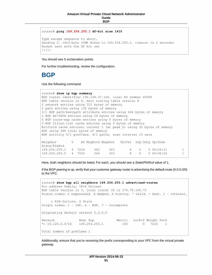
router# ping 169.254.255.1 df-bit size 1410
Type escape sequence to abort.Sending 5, 1410-byte ICMP Echos to 169.254.255.1, timeout is 2 seconds:Packet sent with the DF bit set!!!!!
You should see 5 exclamation points.
For further troubleshooting, review the configuration.
BGPUse the following command.
router# show ip bgp summaryBGP router identifier 192.168.37.160, local AS number 65000BGP table version is 8, main routing table version 82 network entries using 312 bytes of memory2 path entries using 136 bytes of memory3/1 BGP path/bestpath attribute entries using 444 bytes of memory1 BGP AS-PATH entries using 24 bytes of memory0 BGP route-map cache entries using 0 bytes of memory0 BGP filter-list cache entries using 0 bytes of memoryBitfield cache entries: current 1 (at peak 2) using 32 bytes of memoryBGP using 948 total bytes of memoryBGP activity 4/1 prefixes, 4/1 paths, scan interval 15 secs
Neighbor V AS MsgRcvd MsgSent TblVer InQ OutQ Up/Down State/PfxRcd169.254.255.1 4 7224 363 323 8 0 0 00:54:21 1169.254.255.5 4 7224 364 323 8 0 0 00:00:24 1
Here, both neighbors should be listed. For each, you should see a State/PfxRcd value of 1.
If the BGP peering is up, verify that your customer gateway router is advertising the default route (0.0.0.0/0)to the VPC.
router# show bgp all neighbors 169.254.255.1 advertised-routesFor address family: IPv4 UnicastBGP table version is 3, local router ID is 174.78.144.73Status codes: s suppressed, d damped, h history, * valid, > best, i - internal,
r RIB-failure, S StaleOrigin codes: i - IGP, e - EGP, ? - incomplete
Originating default network 0.0.0.0
Network Next Hop Metric LocPrf Weight Path*> 10.120.0.0/16 169.254.255.1 100 0 7224 i
Total number of prefixes 1
Additionally, ensure that you're receiving the prefix corresponding to your VPC from the virtual privategateway.
API Version 2014-06-1591
Amazon Virtual Private Cloud Network AdministratorGuideBGP

router# show ip route bgp 10.0.0.0/16 is subnetted, 1 subnetsB 10.255.0.0 [20/0] via 169.254.255.1, 00:00:20
For further troubleshooting, review the configuration.
Virtual Private Gateway AttachmentMake sure your virtual private gateway is attached to your VPC.Your integration team does this with theAWS Management Console.
If you have questions or need further assistance, please use the Amazon VPC forum.
Troubleshooting Cisco IOS Customer Gatewaywithout Border Gateway Protocol Connectivity
When you troubleshoot the connectivity of a Cisco customer gateway, you need to consider three things:IKE, IPsec and tunnel.You can troubleshoot these areas in any order, but we recommend that you startwith IKE (at the bottom of the network stack) and move up.
IKEUse the following command. The response shows a customer gateway with IKE configured correctly.
router# show crypto isakmp saIPv4 Crypto ISAKMP SAdst src state conn-id slot status174.78.144.73 205.251.233.121 QM_IDLE 2001 0 ACTIVE174.78.144.73 205.251.233.122 QM_IDLE 2002 0 ACTIVE
You should see one or more lines containing an src of the remote gateway specified in the tunnels. Thestate should be QM_IDLE and status should be ACTIVE. The absence of an entry, or any entry in anotherstate, indicates that IKE is not configured properly.
For further troubleshooting, run the following commands to enable log messages that provide diagnosticinformation.
router# term monrouter# debug crypto isakmp
To disable debugging, use the following command.
router# no debug crypto isakmp
IPsecUse the following command. The response shows a customer gateway with IPsec configured correctly.
API Version 2014-06-1592
Amazon Virtual Private Cloud Network AdministratorGuide
Virtual Private Gateway Attachment

router# show crypto ipsec sainterface: Tunnel1 Crypto map tag: Tunnel1-head-0, local addr 174.78.144.73
protected vrf: (none) local ident (addr/mask/prot/port): (0.0.0.0/0.0.0.0/0/0) remote ident (addr/mask/prot/port): (0.0.0.0/0.0.0.0/0/0) current_peer 72.21.209.225 port 500 PERMIT, flags={origin_is_acl,} #pkts encaps: 149, #pkts encrypt: 149, #pkts digest: 149 #pkts decaps: 146, #pkts decrypt: 146, #pkts verify: 146 #pkts compressed: 0, #pkts decompressed: 0 #pkts not compressed: 0, #pkts compr. failed: 0 #pkts not decompressed: 0, #pkts decompress failed: 0 #send errors 0, #recv errors 0
local crypto endpt.: 174.78.144.73, remote crypto endpt.:205.251.233.121 path mtu 1500, ip mtu 1500, ip mtu idb FastEthernet0 current outbound spi: 0xB8357C22(3090512930)
inbound esp sas: spi: 0x6ADB173(112046451) transform: esp-aes esp-sha-hmac , in use settings ={Tunnel, } conn id: 1, flow_id: Motorola SEC 2.0:1, crypto map: Tunnel1-head-0 sa timing: remaining key lifetime (k/sec): (4467148/3189) IV size: 16 bytes replay detection support: Y replay window size: 128 Status: ACTIVE
inbound ah sas:
inbound pcp sas:
outbound esp sas: spi: 0xB8357C22(3090512930) transform: esp-aes esp-sha-hmac , in use settings ={Tunnel, } conn id: 2, flow_id: Motorola SEC 2.0:2, crypto map: Tunnel1-head-0 sa timing: remaining key lifetime (k/sec): (4467148/3189) IV size: 16 bytes replay detection support: Y replay window size: 128 Status: ACTIVE
outbound ah sas:
outbound pcp sas:
interface: Tunnel2 Crypto map tag: Tunnel2-head-0, local addr 205.251.233.122
protected vrf: (none) local ident (addr/mask/prot/port): (0.0.0.0/0.0.0.0/0/0) remote ident (addr/mask/prot/port): (0.0.0.0/0.0.0.0/0/0) current_peer 72.21.209.193 port 500 PERMIT, flags={origin_is_acl,} #pkts encaps: 26, #pkts encrypt: 26, #pkts digest: 26 #pkts decaps: 24, #pkts decrypt: 24, #pkts verify: 24
API Version 2014-06-1593
Amazon Virtual Private Cloud Network AdministratorGuideIPsec

#pkts compressed: 0, #pkts decompressed: 0 #pkts not compressed: 0, #pkts compr. failed: 0 #pkts not decompressed: 0, #pkts decompress failed: 0 #send errors 0, #recv errors 0
local crypto endpt.: 174.78.144.73, remote crypto endpt.:205.251.233.122 path mtu 1500, ip mtu 1500, ip mtu idb FastEthernet0 current outbound spi: 0xF59A3FF6(4120526838)
inbound esp sas: spi: 0xB6720137(3060924727) transform: esp-aes esp-sha-hmac , in use settings ={Tunnel, } conn id: 3, flow_id: Motorola SEC 2.0:3, crypto map: Tunnel2-head-0 sa timing: remaining key lifetime (k/sec): (4387273/3492) IV size: 16 bytes replay detection support: Y replay window size: 128 Status: ACTIVE
inbound ah sas:
inbound pcp sas:
outbound esp sas: spi: 0xF59A3FF6(4120526838) transform: esp-aes esp-sha-hmac , in use settings ={Tunnel, } conn id: 4, flow_id: Motorola SEC 2.0:4, crypto map: Tunnel2-head-0 sa timing: remaining key lifetime (k/sec): (4387273/3492) IV size: 16 bytes replay detection support: Y replay window size: 128 Status: ACTIVE
outbound ah sas:
outbound pcp sas:
For each tunnel interface, you should see both an inbound esp sas and outbound esp sas. This assumesthat an SA is listed (for example, spi: 0x48B456A6), the status is ACTIVE, and IPsec is configured correctly.
For further troubleshooting, use the following command to enable debugging.
router# debug crypto ipsec
To disable debugging, use the following command.
router# no debug crypto ipsec
TunnelFirst, check that you have the necessary firewall rules in place. For a list of the rules, see If You Have aFirewall Between the Internet and Your Customer Gateway (p. 10).
If your firewall rules are set up correctly, then continue troubleshooting with the following command.
API Version 2014-06-1594
Amazon Virtual Private Cloud Network AdministratorGuideTunnel

router# show interfaces tun1Tunnel1 is up, line protocol is up Hardware is Tunnel Internet address is 169.254.249.18/30 MTU 17867 bytes, BW 100 Kbit/sec, DLY 50000 usec, reliability 255/255, txload 2/255, rxload 1/255 Encapsulation TUNNEL, loopback not set Keepalive not set Tunnel source 174.78.144.73, destination 205.251.233.121 Tunnel protocol/transport IPSEC/IP Tunnel TTL 255 Tunnel transport MTU 1427 bytes Tunnel transmit bandwidth 8000 (kbps) Tunnel receive bandwidth 8000 (kbps) Tunnel protection via IPSec (profile "ipsec-vpn-92df3bfb-0") Last input never, output never, output hang never Last clearing of "show interface" counters never Input queue: 0/75/0/0 (size/max/drops/flushes); Total output drops: 0 Queueing strategy: fifo Output queue: 0/0 (size/max) 5 minute input rate 0 bits/sec, 1 packets/sec 5 minute output rate 1000 bits/sec, 1 packets/sec 407 packets input, 30010 bytes, 0 no buffer Received 0 broadcasts, 0 runts, 0 giants, 0 throttles
Ensure the line protocol is up. Check that the tunnel source IP address, source interface, and destinationrespectively match the tunnel configuration for the customer gateway outside IP address, interface, andvirtual private gateway outside IP address. Ensure that Tunnel protection through IPSec is present. Makesure to run the command on both tunnel interfaces. To resolve any problems, review the configuration.
You can also use the following command, replacing 169.254.249.18 with the inside IP address of yourvirtual private gateway.
router# ping 169.254.249.18 df-bit size 1410
Type escape sequence to abort.Sending 5, 1410-byte ICMP Echos to 169.254.249.18, timeout is 2 seconds:Packet sent with the DF bit set!!!!!
You should see five exclamation points.
RoutingTo see your static route table, use the following command.
router# sh ip route static 1.0.0.0/8 is variably subnettedS 10.0.0.0/16 is directly connected, Tunnel1is directly connected, Tunnel2
You should see that the static route for the VPC CIDR through both tunnels exists. If it does not exist,add the static routes as shown here.
API Version 2014-06-1595
Amazon Virtual Private Cloud Network AdministratorGuideTunnel

router# ip route 10.0.0.0 255.255.0.0 Tunnel1 track 100router# ip route 10.0.0.0 255.255.0.0 Tunnel2 track 200
Checking the SLA Monitor
router# show ip sla statistics 100IPSLAs Latest Operation Statistics
IPSLA operation id: 100 Latest RTT: 128 millisecondsLatest operation start time: *18:08:02.155 UTC Wed Jul 15 2012Latest operation return code: OKNumber of successes: 3Number of failures: 0Operation time to live: Forever
router# show ip sla statistics 200IPSLAs Latest Operation Statistics
IPSLA operation id: 200 Latest RTT: 128 millisecondsLatest operation start time: *18:08:02.155 UTC Wed Jul 15 2012Latest operation return code: OKNumber of successes: 3Number of failures: 0Operation time to live: Forever
The value of “Number of successes” indicates whether the SLA monitor has been set up successfully.
For further troubleshooting, review the configuration.
Virtual Private Gateway AttachmentVerify that your virtual private gateway is attached to your VPC.Your integration team does this with theAWS Management Console.
If you have questions or need further assistance, please use the Amazon VPC forum.
Troubleshooting Juniper JunOS CustomerGateway Connectivity
When you troubleshoot the connectivity of a Juniper customer gateway you need to consider four things:IKE, IPsec, tunnel, and BGP.You can troubleshoot these areas in any order, but we recommend thatyou start with IKE (at the bottom of the network stack) and move up.
IKEUse the following command. The response shows a customer gateway with IKE configured correctly.
API Version 2014-06-1596
Amazon Virtual Private Cloud Network AdministratorGuide
Virtual Private Gateway Attachment

user@router> show security ike security-associationsIndex Remote Address State Initiator cookie Responder cookie Mode4 72.21.209.225 UP c4cd953602568b74 0d6d194993328b02 Main3 72.21.209.193 UP b8c8fb7dc68d9173 ca7cb0abaedeb4bb Main
You should see one or more lines containing a Remote Address of the Remote Gateway specified in thetunnels. The State should be UP. The absence of an entry, or any entry in another state (such as DOWN)is an indication that IKE is not configured properly.
For further troubleshooting, enable the IKE trace options (as recommended in the example configurationinformation (see Example: Juniper JunOS Device (p. 40)). Then run the following command to print avariety of debugging messages to the screen.
user@router> monitor start kmd
From an external host, you can retrieve the entire log file with the following command.
scp [email protected]:/var/log/kmd
IPsecUse the following command. The response shows a customer gateway with IPsec configured correctly.
user@router> show security ipsec security-associationsTotal active tunnels: 2ID Gateway Port Algorithm SPI Life:sec/kb Mon vsys<131073 72.21.209.225 500 ESP:aes-128/sha1 df27aae4 326/ unlim - 0>131073 72.21.209.225 500 ESP:aes-128/sha1 5de29aa1 326/ unlim - 0<131074 72.21.209.193 500 ESP:aes-128/sha1 dd16c453 300/ unlim - 0>131074 72.21.209.193 500 ESP:aes-128/sha1 c1e0eb29 300/ unlim - 0
Specifically, you should see at least two lines per Gateway address (corresponding to the RemoteGateway). Note the carets at the beginning of each line (< >) which indicate the direction of traffic for theparticular entry.The output has separate lines for inbound traffic ("<", traffic from the virtual private gatewayto this customer gateway) and outbound traffic (">").
For further troubleshooting, enable the IKE traceoptions (for more information, see the preceding sectionabout IKE).
TunnelFirst, double-check that you have the necessary firewall rules in place. For a list of the rules, see If YouHave a Firewall Between the Internet and Your Customer Gateway (p. 10).
If your firewall rules are set up correctly, then continue troubleshooting with the following command.
user@router> show interfaces st0.1 Logical interface st0.1 (Index 70) (SNMP ifIndex 126) Flags: Point-To-Point SNMP-Traps Encapsulation: Secure-Tunnel Input packets : 8719 Output packets: 41841 Security: Zone: Trust Allowed host-inbound traffic : bgp ping ssh traceroute
API Version 2014-06-1597
Amazon Virtual Private Cloud Network AdministratorGuideIPsec
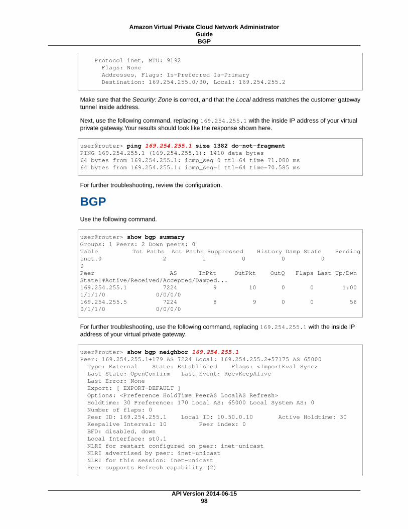
Protocol inet, MTU: 9192 Flags: None Addresses, Flags: Is-Preferred Is-Primary Destination: 169.254.255.0/30, Local: 169.254.255.2
Make sure that the Security: Zone is correct, and that the Local address matches the customer gatewaytunnel inside address.
Next, use the following command, replacing 169.254.255.1 with the inside IP address of your virtualprivate gateway.Your results should look like the response shown here.
user@router> ping 169.254.255.1 size 1382 do-not-fragmentPING 169.254.255.1 (169.254.255.1): 1410 data bytes64 bytes from 169.254.255.1: icmp_seq=0 ttl=64 time=71.080 ms64 bytes from 169.254.255.1: icmp_seq=1 ttl=64 time=70.585 ms
For further troubleshooting, review the configuration.
BGPUse the following command.
user@router> show bgp summaryGroups: 1 Peers: 2 Down peers: 0Table Tot Paths Act Paths Suppressed History Damp State Pendinginet.0 2 1 0 0 0 0Peer AS InPkt OutPkt OutQ Flaps Last Up/Dwn State|#Active/Received/Accepted/Damped...169.254.255.1 7224 9 10 0 0 1:00 1/1/1/0 0/0/0/0169.254.255.5 7224 8 9 0 0 56 0/1/1/0 0/0/0/0
For further troubleshooting, use the following command, replacing 169.254.255.1 with the inside IPaddress of your virtual private gateway.
user@router> show bgp neighbor 169.254.255.1Peer: 169.254.255.1+179 AS 7224 Local: 169.254.255.2+57175 AS 65000 Type: External State: Established Flags: <ImportEval Sync> Last State: OpenConfirm Last Event: RecvKeepAlive Last Error: None Export: [ EXPORT-DEFAULT ] Options: <Preference HoldTime PeerAS LocalAS Refresh> Holdtime: 30 Preference: 170 Local AS: 65000 Local System AS: 0 Number of flaps: 0 Peer ID: 169.254.255.1 Local ID: 10.50.0.10 Active Holdtime: 30 Keepalive Interval: 10 Peer index: 0 BFD: disabled, down Local Interface: st0.1 NLRI for restart configured on peer: inet-unicast NLRI advertised by peer: inet-unicast NLRI for this session: inet-unicast Peer supports Refresh capability (2)
API Version 2014-06-1598
Amazon Virtual Private Cloud Network AdministratorGuideBGP

Restart time configured on the peer: 120 Stale routes from peer are kept for: 300 Restart time requested by this peer: 120 NLRI that peer supports restart for: inet-unicast NLRI that restart is negotiated for: inet-unicast NLRI of received end-of-rib markers: inet-unicast NLRI of all end-of-rib markers sent: inet-unicast Peer supports 4 byte AS extension (peer-as 7224) Table inet.0 Bit: 10000 RIB State: BGP restart is complete Send state: in sync Active prefixes: 1 Received prefixes: 1 Accepted prefixes: 1 Suppressed due to damping: 0 Advertised prefixes: 1Last traffic (seconds): Received 4 Sent 8 Checked 4 Input messages: Total 24 Updates 2 Refreshes 0 Octets 505Output messages: Total 26 Updates 1 Refreshes 0 Octets 582Output Queue[0]: 0
Here you should see Received prefixes and Advertised prefixes listed at 1 each. This should be withinthe Table inet.0 section.
If the State is not Established, check the Last State and Last Error for details of what is required tocorrect the problem.
If the BGP peering is up, verify that your customer gateway router is advertising the default route (0.0.0.0/0)to the VPC.
user@router> show route advertising-protocol bgp 169.254.255.1
inet.0: 10 destinations, 11 routes (10 active, 0 holddown, 0 hidden) Prefix Nexthop MED Lclpref AS path* 0.0.0.0/0 Self I
Additionally, ensure that you're receiving the prefix corresponding to your VPC from the virtual privategateway.
user@router> show route receive-protocol bgp 169.254.255.1
inet.0: 10 destinations, 11 routes (10 active, 0 holddown, 0 hidden) Prefix Nexthop MED Lclpref AS path* 10.110.0.0/16 169.254.255.1 100 7224 I
Virtual Private Gateway AttachmentMake sure your virtual private gateway is attached to your VPC.Your integration team does this with theAWS Management Console.
If you have questions or need further assistance, please use the Amazon VPC forum.
API Version 2014-06-1599
Amazon Virtual Private Cloud Network AdministratorGuide
Virtual Private Gateway Attachment

Troubleshooting Juniper ScreenOS CustomerGateway Connectivity
When you troubleshoot the connectivity of a Juniper ScreenOS-based customer gateway you need toconsider four things: IKE, IPsec, tunnel, and BGP.You can troubleshoot these areas in any order, butwe recommend that you start with IKE (at the bottom of the network stack) and move up.
IKE and IPsecUse the following command. The response shows a customer gateway with IKE configured correctly.
ssg5-serial-> get satotal configured sa: 2HEX ID Gateway Port Algorithm SPI Life:sec kb Sta PID vsys00000002< 72.21.209.225 500 esp:a128/sha1 80041ca4 3385 unlim A/- -1 000000002> 72.21.209.225 500 esp:a128/sha1 8cdd274a 3385 unlim A/- -1 000000001< 72.21.209.193 500 esp:a128/sha1 ecf0bec7 3580 unlim A/- -1 000000001> 72.21.209.193 500 esp:a128/sha1 14bf7894 3580 unlim A/- -1 0
You should see one or more lines containing a Remote Address of the Remote Gateway specified in thetunnels. The Sta should be A/- and the SPI should be a hexadecimal number other than 00000000.Entries in other states indicate that IKE is not configured properly.
For further troubleshooting, enable the IKE trace options (as recommended in the example configurationinformation (see Example: Juniper ScreenOS Device (p. 51)).
TunnelFirst, double-check that you have the necessary firewall rules in place. For a list of the rules, see If YouHave a Firewall Between the Internet and Your Customer Gateway (p. 10).
If your firewall rules are set up correctly, then continue troubleshooting with the following command.
ssg5-serial-> get interface tunnel.1 Interface tunnel.1: description tunnel.1 number 20, if_info 1768, if_index 1, mode route link ready vsys Root, zone Trust, vr trust-vr admin mtu 1500, operating mtu 1500, default mtu 1500 *ip 169.254.255.2/30 *manage ip 169.254.255.2 route-deny disable bound vpn: IPSEC-1
Next-Hop Tunnel Binding table Flag Status Next-Hop(IP) tunnel-id VPN
pmtu-v4 disabled ping disabled, telnet disabled, SSH disabled, SNMP disabled web disabled, ident-reset disabled, SSL disabled
API Version 2014-06-15100
Amazon Virtual Private Cloud Network AdministratorGuide
Juniper ScreenOS Customer Gateway Connectivity

OSPF disabled BGP enabled RIP disabled RIPng disabled mtrace disabled PIM: not configured IGMP not configured NHRP disabled bandwidth: physical 0kbps, configured egress [gbw 0kbps mbw 0kbps] configured ingress mbw 0kbps, current bw 0kbps total allocated gbw 0kbps
Make sure that you see link:ready, and that the IP address matches the customer gateway tunnel insideaddress.
Next, use the following command, replacing 169.254.255.1 with the inside IP address of your virtualprivate gateway.Your results should look like the response shown here.
ssg5-serial-> ping 169.254.255.1Type escape sequence to abort
Sending 5, 100-byte ICMP Echos to 169.254.255.1, timeout is 1 seconds!!!!!Success Rate is 100 percent (5/5), round-trip time min/avg/max=32/32/33 ms
For further troubleshooting, review the configuration.
BGPUse the following command.
ssg5-serial-> get vrouter trust-vr protocol bgp neighborPeer AS Remote IP Local IP Wt Status State ConnID Up/Down-------------------------------------------------------------------------------- 7224 169.254.255.1 169.254.255.2 100 Enabled ESTABLISH 10 00:01:01
7224 169.254.255.5 169.254.255.6 100 Enabled ESTABLISH 11 00:00:59
Both BGP peers should be listed as State: ESTABLISH, which means the BGP connection to the virtualprivate gateway is active.
For further troubleshooting, use the following command, replacing 169.254.255.1 with the inside IPaddress of your virtual private gateway.
ssg5-serial-> get vr trust-vr prot bgp neigh 169.254.255.1peer: 169.254.255.1, remote AS: 7224, admin status: enabletype: EBGP, multihop: 0(disable), MED: node default(0)connection state: ESTABLISH, connection id: 18 retry interval: node de fault(120s), cur retry time 15sconfigured hold time: node default(90s), configured keepalive: node default(30s)configured adv-interval: default(30s)designated local IP: n/alocal IP address/port: 169.254.255.2/13946, remote IP address/port: 169.254.255.1/179router ID of peer: 169.254.255.1, remote AS: 7224negotiated hold time: 30s, negotiated keepalive interval: 10sroute map in name: , route map out name:
API Version 2014-06-15101
Amazon Virtual Private Cloud Network AdministratorGuideBGP

weight: 100 (default)self as next hop: disablesend default route to peer: disableignore default route from peer: disablesend community path attribute: noreflector client: noNeighbor Capabilities: Route refresh: advertised and received Address family IPv4 Unicast: advertised and receivedforce reconnect is disabletotal messages to peer: 106, from peer: 106update messages to peer: 6, from peer: 4Tx queue length 0, Tx queue HWM: 1route-refresh messages to peer: 0, from peer: 0last reset 00:05:33 ago, due to BGP send Notification(Hold Timer Expired)(code 4 : subcode 0)number of total successful connections: 4connected: 2 minutes 6 secondsElapsed time since last update: 2 minutes 6 seconds
If the BGP peering is up, verify that your customer gateway router is advertising the default route (0.0.0.0/0)to the VPC. Note that this command applies to ScreenOS version 6.2.0 and higher.
ssg5-serial-> get vr trust-vr protocol bgp rib neighbor 169.254.255.1 advertisedi: IBGP route, e: EBGP route, >: best route, *: valid route Prefix Nexthop Wt Pref Med Orig AS-Path-------------------------------------------------------------------------------------->i 0.0.0.0/0 0.0.0.0 32768 100 0 IGPTotal IPv4 routes advertised: 1
Additionally, ensure that you're receiving the prefix corresponding to your VPC from the virtual privategateway. Note that this command applies to ScreenOS version 6.2.0 and higher.
ssg5-serial-> get vr trust-vr protocol bgp rib neighbor 169.254.255.1 receivedi: IBGP route, e: EBGP route, >: best route, *: valid route Prefix Nexthop Wt Pref Med Orig AS-Path-------------------------------------------------------------------------------------->e* 10.0.0.0/16 169.254.255.1 100 100 100 IGP 7224Total IPv4 routes received: 1
Virtual Private Gateway AttachmentMake sure your virtual private gateway is attached to your VPC.Your integration team does this with theAWS Management Console.
If you have questions or need further assistance, please use the Amazon VPC forum.
API Version 2014-06-15102
Amazon Virtual Private Cloud Network AdministratorGuide
Virtual Private Gateway Attachment

Troubleshooting Yamaha Customer GatewayConnectivity
When you troubleshoot the connectivity of a Yamaha customer gateway you need to consider four things:IKE, IPsec, tunnel, and BGP.You can troubleshoot these areas in any order, but we recommend thatyou start with IKE (at the bottom of the network stack) and move up.
IKEUse the following command. The response shows a customer gateway with IKE configured correctly.
# show ipsec sa gateway 1sgw flags local-id remote-id # of sa--------------------------------------------------------------------------1 U K YOUR_LOCAL_NETWORK_ADDRESS 72.21.209.225 i:2 s:1 r:1
You should see a line containing a remote-id of the Remote Gateway specified in the tunnels.You canlist all the security associations (SAs) by omitting the tunnel number.
For further troubleshooting, run the following commands to enable DEBUG level log messages thatprovide diagnostic information.
# syslog debug on# ipsec ike log message-info payload-info key-info
To cancel the logged items, use the following command.
# no ipsec ike log# no syslog debug on
IPsecUse the following command. The response shows a customer gateway with IPsec configured correctly.
# show ipsec sa gateway 1 detailSA[1] Duration: 10675sLocal ID: YOUR_LOCAL_NETWORK_ADDRESSRemote ID: 72.21.209.225Protocol: IKEAlgorithm: AES-CBC, SHA-1, MODP 1024bit
SPI: 6b ce fd 8a d5 30 9b 02 0c f3 87 52 4a 87 6e 77 Key: ** ** ** ** ** (confidential) ** ** ** ** **----------------------------------------------------SA[2] Duration: 1719sLocal ID: YOUR_LOCAL_NETWORK_ADDRESSRemote ID: 72.21.209.225Direction: sendProtocol: ESP (Mode: tunnel)Algorithm: AES-CBC (for Auth.: HMAC-SHA)SPI: a6 67 47 47
API Version 2014-06-15103
Amazon Virtual Private Cloud Network AdministratorGuide
Yamaha Customer Gateway Connectivity

Key: ** ** ** ** ** (confidential) ** ** ** ** **----------------------------------------------------SA[3] Duration: 1719sLocal ID: YOUR_LOCAL_NETWORK_ADDRESSRemote ID: 72.21.209.225Direction: receiveProtocol: ESP (Mode: tunnel)Algorithm: AES-CBC (for Auth.: HMAC-SHA)SPI: 6b 98 69 2b Key: ** ** ** ** ** (confidential) ** ** ** ** **----------------------------------------------------SA[4] Duration: 10681sLocal ID: YOUR_LOCAL_NETWORK_ADDRESSRemote ID: 72.21.209.225Protocol: IKEAlgorithm: AES-CBC, SHA-1, MODP 1024bitSPI: e8 45 55 38 90 45 3f 67 a8 74 ca 71 ba bb 75 ee Key: ** ** ** ** ** (confidential) ** ** ** ** **----------------------------------------------------
For each tunnel interface, you should see both receive sas and send sas.
For further troubleshooting, use the following command to enable debugging.
# syslog debug on # ipsec ike log message-info payload-info key-info
Use the following command to disable debugging.
# no ipsec ike log # no syslog debug on
TunnelFirst, check that you have the necessary firewall rules in place. For a list of the rules, see If You Have aFirewall Between the Internet and Your Customer Gateway (p. 10).
If your firewall rules are set up correctly, then continue troubleshooting with the following command.
# show status tunnel 1TUNNEL[1]: Description: Interface type: IPsec Current status is Online. from 2011/08/15 18:19:45. 5 hours 7 minutes 58 seconds connection. Received: (IPv4) 3933 packets [244941 octets] (IPv6) 0 packet [0 octet] Transmitted: (IPv4) 3933 packets [241407 octets] (IPv6) 0 packet [0 octet]
Ensure the current status is online. Also, ensure that Interface type is IPsec. Make sure to run the commandon both tunnel interfaces. To resolve any problems here, review the configuration.
API Version 2014-06-15104
Amazon Virtual Private Cloud Network AdministratorGuideTunnel

BGPUse the following command.
# show status bgp neighborBGP neighbor is 169.254.255.1, remote AS 7224, local AS 65000, external link BGP version 0, remote router ID 0.0.0.0 BGP state = Active Last read 00:00:00, hold time is 0, keepalive interval is 0 seconds Received 0 messages, 0 notifications, 0 in queue Sent 0 messages, 0 notifications, 0 in queue Connection established 0; dropped 0 Last reset neverLocal host: unspecifiedForeign host: 169.254.255.1, Foreign port: 0
BGP neighbor is 169.254.255.5, remote AS 7224, local AS 65000, external link BGP version 0, remote router ID 0.0.0.0 BGP state = Active Last read 00:00:00, hold time is 0, keepalive interval is 0 seconds Received 0 messages, 0 notifications, 0 in queue Sent 0 messages, 0 notifications, 0 in queue Connection established 0; dropped 0 Last reset neverLocal host: unspecifiedForeign host: 169.254.255.5, Foreign port:
Here, both neighbors should be listed. For each, you should see a BGP state value of Active.
If the BGP peering is up, verify that your customer gateway router is advertising the default route (0.0.0.0/0)to the VPC.
# show status bgp neighbor 169.254.255.1 advertised-routes Total routes: 1*: valid route Network Next Hop Metric LocPrf Path* default 0.0.0.0 0 IGP
Additionally, ensure that you're receiving the prefix corresponding to your VPC from the virtual privategateway.
# show ip routeDestination Gateway Interface Kind Additional Info.default ***.***.***.*** LAN3(DHCP) static 10.0.0.0/16 169.254.255.1 TUNNEL[1] BGP path=10124
For further troubleshooting, review the configuration.
Virtual Private Gateway AttachmentMake sure your virtual private gateway is attached to your VPC.Your integration team does this with theAWS Management Console.
If you have questions or need further assistance, please use the Amazon VPC forum.
API Version 2014-06-15105
Amazon Virtual Private Cloud Network AdministratorGuideBGP

Troubleshooting Generic Device CustomerGateway Connectivity Using Border GatewayProtocol
The following diagram and table provide general instructions for troubleshooting a customer gateway thatuses Border Gateway Protocol for devices other than those listed in this guide.
TipWhen troubleshooting problems, you might find it useful to enable the debug features of yourgateway device. Consult your gateway device vendor for details.
API Version 2014-06-15106
Amazon Virtual Private Cloud Network AdministratorGuide
Generic Device Customer Gateway Connectivity

Determine if an IKE Security Association exists.
An IKE security association is required to exchange keys that are used to establish theIPsec Security Association.
If no IKE security association exists, review your IKE configuration settings.You mustconfigure the encryption, authentication, perfect-forward-secrecy, and mode parametersas listed in the customer gateway configuration.
If an IKE security association exists, move on to IPsec.
Determine if an IPsec Security Association exists.
An IPsec security association is the tunnel itself. Query your customer gateway to determineif an IPsec Security Association is active. Proper configuration of the IPsec SA is critical.You must configure the encryption, authentication, perfect-forward-secrecy, and modeparameters as listed in the customer gateway configuration.
If no IPsec Security Association exists, review your IPsec configuration.
If an IPsec Security Association exists, move on to the tunnel.
Confirm the required firewall rules are set up (for a list of the rules, see If You Have aFirewall Between the Internet and Your Customer Gateway (p. 10)). If they are, moveforward.
Determine if there is IP connectivity via the tunnel.
Each side of the tunnel has an IP address as specified in the customer gatewayconfiguration.The virtual private gateway address is the address used as the BGP neighboraddress. From your customer gateway, ping this address to determine if IP traffic is beingproperly encrypted and decrypted.
If the ping isn't successful, review your tunnel interface configuration to ensure the properIP address is configured.
If the ping is successful, move on to BGP.
Determine if the BGP peering is active.
For each tunnel, do the following:
• On your customer gateway, determine if the BGP status is Active or Established. It maytake approximately 30 seconds for a BGP peering to become active.
• Ensure that the customer gateway is advertising the default route (0.0.0.0/0) to thevirtual private gateway.
If the tunnels are not in this state, review your BGP configuration.
If the BGP peering is established, you are receiving a prefix, and you are advertising aprefix, your tunnel is configured correctly. Ensure both tunnels are in this state, and you'redone.
Make sure your virtual private gateway is attached to your VPC.Your integration teamdoes this with the AWS Management Console.
For general testing instructions applicable to all customer gateways, see How to Test the CustomerGateway Configuration (p. 75).
API Version 2014-06-15107
Amazon Virtual Private Cloud Network AdministratorGuide
Generic Device Customer Gateway Connectivity

If you have questions or need further assistance, please use the Amazon VPC forum.
Troubleshooting Generic Device CustomerGateway without Border Gateway ProtocolConnectivity
The following diagram and table provide general instructions for troubleshooting a customer gatewaydevice that does not use Border Gateway Protocol.
TipWhen troubleshooting problems, you might find it useful to enable the debug features of yourgateway device. Consult your gateway device vendor for details.
API Version 2014-06-15108
Amazon Virtual Private Cloud Network AdministratorGuide
Generic Device Customer Gateway Connectivity (withoutBGP)

API Version 2014-06-15109
Amazon Virtual Private Cloud Network AdministratorGuide
Generic Device Customer Gateway Connectivity (withoutBGP)

Determine if an IKE Security Association exists.
An IKE security association is required to exchange keys that are used to establish theIPsec Security Association.
If no IKE security association exists, review your IKE configuration settings.You mustconfigure the encryption, authentication, perfect-forward-secrecy, and mode parametersas listed in the customer gateway configuration.
If an IKE security association exists, move on to IPsec.
Determine if an IPsec Security Association exists.
An IPsec security association is the tunnel itself. Query your customer gateway to determineif an IPsec Security Association is active. Proper configuration of the IPsec SA is critical.You must configure the encryption, authentication, perfect-forward-secrecy, and modeparameters as listed in the customer gateway configuration.
If no IPsec Security Association exists, review your IPsec configuration.
If an IPsec Security Association exists, move on to the tunnel.
Confirm the required firewall rules are set up (for a list of the rules, see If You Have aFirewall Between the Internet and Your Customer Gateway (p. 10)). If they are, moveforward.
Determine if there is IP connectivity via the tunnel.
Each side of the tunnel has an IP address as specified in the customer gatewayconfiguration.The virtual private gateway address is the address used as the BGP neighboraddress. From your customer gateway, ping this address to determine if IP traffic is beingproperly encrypted and decrypted.
If the ping isn't successful, review your tunnel interface configuration to ensure the properIP address is configured.
If the ping is successful, move on to Routing.
Routing:
For each tunnel, do the following:
• Verify that you have added a static route to your VPC CIDR with the tunnels as the nexthop.
• Verify that you have added a static route on the AWS console, to tell the VGW to routetraffic back to your internal networks.
If the tunnels are not in this state, review your device configuration.
Ensure both tunnels are in this state, and you're done.
Staticroutes
Make sure your virtual private gateway is attached to your VPC.Your integration teamdoes this with the AWS Management Console.
If you have questions or need further assistance, please use the Amazon VPC forum.
API Version 2014-06-15110
Amazon Virtual Private Cloud Network AdministratorGuide
Generic Device Customer Gateway Connectivity (withoutBGP)

Configuring Windows Server 2008R2 as a Customer Gateway for YourVPC
You can configure Windows Server 2008 R2 as a customer gateway for your VPC. Use the followingprocess whether you are running Windows Server 2008 R2 on an EC2 instance in a VPC, or on yourown server:
• Step 1: Create a VPN Connection (p. 112)
• Step 2: Download the Configuration File for the VPN Connection (p. 112)
• Step 3: Configure the Server Using Data from the Configuration File (p. 113)
• Step 4: Set Up the VPN Tunnel (p. 116)
• Step 5: Enable Dead Gateway Detection (p. 123)
• Step 6: Test the VPN Connection (p. 124)
PrerequisitesBefore you begin, make sure that you have the following:
• Windows Server 2008 R2 on your own network, or on an EC2 instance in a VPC
• The CIDR range for your network in which the Windows server is located, for example, 172.31.0.0/16
• The CIDR range for your VPC, for example, 10.0.0.0/16
• A customer gateway that specifies the IP address of the Windows Server 2008 R2 server
NoteThe IP address must be static and can't be behind a device performing NAT; if your customergateway is a Windows server instance, you can use an Elastic IP address.
• A virtual private gateway attached to your VPC
• A subnet in your VPC for launching instances that will communicate with the Windows server
• Routing for your VPN connection:
API Version 2014-06-15111
Amazon Virtual Private Cloud Network AdministratorGuide
Prerequisites

Add a route to your subnet's route table with the virtual private gateway as the target, and the Windowsserver's network (CIDR range) as the destination.
•
• Enable route propagation for the virtual private gateway. For more information about route tables,see Route Tables in the Amazon Virtual Private Cloud User Guide.
• A security group configuration that allows communication between your network and your VPC:
• If your customer gateway is a Windows server instance in a VPC, its security group requires thefollowing outbound custom protocol rules for IPsec traffic: IP protocol 50, IP protocol 51, and UDP500. By default, a security group allows all outbound traffic, so this step is only required if the securitygroup's outbound rules have been modified from their original state.
• For instances that you launch in your VPC, add rules to their security groups that allow inbound RDPor SSH access from your network. This enables you to connect to instances in your VPC from yournetwork. For more information, see Security Groups for Your VPC in the Amazon Virtual PrivateCloud User Guide.
• For instances that you launch in your VPC, add a rule to their security groups that allows inboundICMP access. This enables you to test your VPN connection by pinging an instance in your VPCfrom your Windows server.
If you launched the Windows server instance from a current Amazon AMI, you might not be able to routetraffic from other instances without updating your adapter settings.
To update your adapter settings
1. From your Windows server instance, open Control Panel, and start the Device Manager.
2. Expand the Network adapters node.
3. Right-click the Citrix network adapter, and then click Properties.
4. On the Advanced tab, disable the IPv4 Checksum Offload, TCP Checksum Offload (IPv4), andUDP Checksum Offload (IPv4) properties, and then click OK.
Step 1: Create a VPN ConnectionTo create a VPN connection
1. Open the Amazon VPC console.
2. In the navigation pane, click VPN Connections, and then click Create VPN Connection.
3. Select the virtual private gateway and customer gateway from the lists. Select the Static routingoption, enter the Static IP Prefixes values for your server's network in CIDR notation (for example,172.31.0.0/16), and then click Yes, Create.
Step 2: Download the Configuration File for theVPN Connection
To download your configuration file
1. Click VPN Connections in the navigation pane.
2. Select your VPN connection, and then click Download Configuration.
3. Select Microsoft as the vendor, Windows Server as the platform, and 2008 R2 as the software.Click Yes, Download.You can open the file or save it.
API Version 2014-06-15112
Amazon Virtual Private Cloud Network AdministratorGuide
Step 1: Create a VPN Connection

Step 3: Configure the Server Using Data fromthe Configuration File
The configuration file contains a section of information similar to the following example.You’ll see thisinformation presented twice, one time for each tunnel.You'll use this information when configuring theWindows Server 2008 R2 server.
vgw-1a2b3c4d Tunnel1-------------------------------------------------------------------- Local Tunnel Endpoint: 203.0.113.1Remote Tunnel Endpoint: 203.83.222.237Endpoint 1: [Your_Static_Route_IP_Prefix]Endpoint 2: [Your_VPC_CIDR_Block]Preshared key: xCjNLsLoCmKsakwcdoR9yX6GsEXAMPLE
Local Tunnel EndpointThe IP address for the customer gateway - in this case, your Windows server - that terminates theVPN connection on your network's side.
Remote Tunnel EndpointOne of two IP addresses for the virtual private gateway that terminates the VPN connection on theAWS side.
Endpoint 1The IP prefix that you specified as a static route when you created the VPN connection. These arethe IP addresses on your network that are allowed to use the VPN connection to access your VPC.
Endpoint 2The IP address range (CIDR block) of the VPC attached to the virtual private gateway (for example10.0.0.0/16).
Preshared keyThe pre-shared key that is used to establish the IPsec VPN connection between Local TunnelEndpoint and Remote Tunnel Endpoint.
We suggest that you configure both tunnels as part of the VPN connection. Each tunnel connects to aseparate VPN concentrator on the Amazon side of the VPN connection. Although only one tunnel at atime is up, the second tunnel automatically establishes itself if the first tunnel goes down. Having redundanttunnels ensure continuous availability in the case of a device failure. Because only one tunnel is availableat a time, the AWS Management Console displays a yellow icon indicating that one tunnel is down. Thisis expected behavior, so there's no action required from you.
With two tunnels configured, if a device failure occurs within AWS, your VPN connection automaticallyfails over to the second tunnel of the AWS virtual private gateway within a matter of minutes. When youconfigure your customer gateway, it's important that you configure both tunnels.
NoteFrom time to time, AWS performs routine maintenance on the virtual private gateway. Thismaintenance may disable one of the two tunnels of your VPN connection for a brief period oftime.Your VPN connection automatically fails over to the second tunnel while we perform thismaintenance.
Additional information regarding the Internet Key Exchange (IKE) and IPsec Security Associations (SA)is presented in the downloaded configuration file. Because the AWS VPC VPN suggested settings arethe same as the Windows Server 2008 R2 default IPsec configuration settings, minimal work is neededon your part.
API Version 2014-06-15113
Amazon Virtual Private Cloud Network AdministratorGuide
Step 3: Configure the Server Using Data from theConfiguration File

MainModeSecMethods: DHGroup2-AES128-SHA1,DHGroup2-3DES-SHA1 MainModeKeyLifetime: 480min,0sec QuickModeSecMethods: ESP:SHA1-AES128+60min+100000kb, ESP:SHA1-3D ES+60min+100000kb QuickModePFS: DHGroup2
MainModeSecMethodsThe encryption and authentication algorithms for the IKE SA. These are the suggested settings forthe VPN connection, and are the default settings for Windows Server 2008 R2 IPsec VPN connections.
MainModeKeyLifetimeThe IKE SA key lifetime. This is the suggested setting for the VPN connection, and is the defaultsetting for Windows Server 2008 R2 IPsec VPN connections.
QuickModeSecMethodsThe encryption and authentication algorithms for the IPsec SA.These are the suggested settings forthe VPN connection, and are the default settings for Windows Server 2008 R2 IPsec VPN connections.
QuickModePFSWe suggest the use of master key perfect forward secrecy (PFS) for your IPsec sessions.
To configure the Windows Server 2008 R2 server as the customer gateway
1. Log on to the Windows Server 2008 R2 server.
2. Click Start, point to All Programs, point to Administrative Tools, and then click Server Manager.
3. Install Routing and Remote Access Services:
a. In the Server Manager navigation pane, click Roles.
b. In the Roles pane, click Add Roles.
c. On the Before You Begin page, verify that your server meets the prerequisites and then clickNext.
d. On the Select Server Roles page, click Network Policy and Access Services, and then clickNext.
e. On the Network Policy and Access Services page, click Next.
f. On the Select Role Services page, click Routing and Remote Access Services, leave RemoteAccess Service and Routing selected, and then click Next.
API Version 2014-06-15114
Amazon Virtual Private Cloud Network AdministratorGuide
Step 3: Configure the Server Using Data from theConfiguration File

g. On the Confirm Installation Selections page, click Install.
h. When the wizard completes, click Close.
To configure and enable Routing and Remote Access Server
1. In the Server Manager navigation pane, expand Roles, and then expand Network Policy andAccess.
2. Right-click Routing and Remote Access Server, and then click Configure and Enable Routingand Remote Access.
3. In the Routing and Remote Access Setup Wizard, on the Welcome page, click Next.
4. On the Configuration page, click Custom Configuration, and then click Next.
5. Click LAN routing, and then click Next.
6. Click Finish.
7. When prompted by the Routing and Remote Access dialog box, click Start service.
API Version 2014-06-15115
Amazon Virtual Private Cloud Network AdministratorGuide
Step 3: Configure the Server Using Data from theConfiguration File

Step 4: Set Up the VPN TunnelYou can configure the VPN tunnel by running the netsh scripts included in the downloaded configurationfile, or by using the New Connection Security Rule Wizard on the Windows server.
ImportantWe suggest that you use master key perfect forward secrecy (PFS) for your IPsec sessions.However, you can't enable PFS using the Windows Server 2008 R2 user interface; you can onlyenable this setting by running the netsh script with qmpfs=dhgroup2. Therefore, you shouldconsider your requirements before you pick an option. For more information, go to Key exchangesettings in the Microsoft TechNet Library.
Option 1: Run netsh ScriptCopy the netsh script from the downloaded configuration file and replace the variables. The following isan example script.
netsh advfirewall consec add rule Name="VGW-1a2b3c4d Tunnel 1" Enable=Yes ^Profile=any Type=Static Mode=Tunnel LocalTunnelEndpoint=Windows_Server_Private_IP_address ^RemoteTunnelEndpoint=203.83.222.236 Endpoint1=Static_Route_IP_Prefix ^Endpoint2=VPC_CIDR_Block Protocol=Any Action=RequireInClearOut ^Auth1=ComputerPSK Auth1PSK=xCjNLsLoCmKsakwcdoR9yX6Gsexample ^QMSecMethods=ESP:SHA1-AES128+60min+100000kb ^ExemptIPsecProtectedConnections=No ApplyAuthz=No QMPFS=dhgroup2
Name:You can replace the suggested name (VGW-1a2b3c4d Tunnel 1) with a name of your choice.
LocalTunnelEndpoint: Enter the private IP address of the Windows server on your network.
Endpoint1: The CIDR block of your network on which the Windows server resides, for example,172.31.0.0/16
Endpoint2: The CIDR block of your VPC or a subnet in your VPC, for example, 10.0.0.0/16
Run the updated script in a command prompt window. (The ^ enables you to cut and paste wrapped textat the command line.) To set up the second VPN tunnel for this VPN connection, repeat the process usingthe second netsh script in the configuration file.
For more information about the netsh parameters, go to Netsh AdvFirewall Consec Commands in theMicrosoft TechNet Library.
Option 2: Use the Windows Server User InterfaceYou can also use the Windows server user interface to set up the VPN tunnel. This section guides youthrough the steps.
ImportantYou can't enable master key perfect forward secrecy (PFS) using the Windows Server 2008 R2user interface. Therefore, if you decide to use PFS, you must use the netsh scripts described inoption 1 instead of the user interface described in this option.
• 2.1: Configure a Security Rule for a VPN Tunnel (p. 117)
• 2.3: Confirm the Tunnel Configuration (p. 120)
• 2.4: Configure the Windows Firewall (p. 120)
API Version 2014-06-15116
Amazon Virtual Private Cloud Network AdministratorGuide
Step 4: Set Up the VPN Tunnel

2.1: Configure a Security Rule for a VPN TunnelIn this section, you will configure a security rule on your Windows server to create a VPN tunnel.
To configure a security rule for a VPN tunnel
1. In the Server Manager navigation pane, expand Configuration, and then expand Windows Firewallwith Advanced Security.
2. Right-click Connection Security Rules, and then click New Rule.
3. In the New Connection Security Rule wizard, on the Rule Type page, click Tunnel, and then clickNext.
4. On the Tunnel Type page, under What type of tunnel would you like to create, click CustomConfiguration. Under Would you like to exempt IPsec-protected connections from this tunnel,leave the default value checked (No. Send all network traffic that matches this connectionsecurity rule through the tunnel), and then click Next.
5. On the Requirements page, click Require authentication for inbound connections. Do notestablish tunnels for outbound connections, and then click Next.
6. On Tunnel Endpoints page, under Which computers are in Endpoint 1, click Add. Enter the CIDRrange of your network (behind your Windows server customer gateway), and then click OK. (Notethat the range can include the IP address of your customer gateway.)
7. Under What is the local tunnel endpoint (closest to computer in Endpoint 1), click Edit. Enterthe private IP address of your Windows server, and then click OK.
8. Under What is the remote tunnel endpoint (closest to computers in Endpoint 2), click Edit.Enter the IP address of the virtual private gateway for Tunnel 1 from the configuration file (see RemoteTunnel Endpoint), and then click OK.
API Version 2014-06-15117
Amazon Virtual Private Cloud Network AdministratorGuide
Option 2: Use the Windows Server User Interface

ImportantIf you are repeating this procedure for Tunnel 2, be sure to select the endpoint for Tunnel2.
9. Under Which computers are in Endpoint 2, click Add. Enter the CIDR block of your VPC, and thenclick OK.
ImportantYou must scroll in the dialog box until you locate Which computers are in Endpoint 2. Donot click Next until you have completed this step, or you won't be able to connect to yourserver.
10. Confirm that all the settings you've specified are correct, and then click Next.
11. On the Authentication Method page, select Advanced, and then click Customize.
12. Under First authentication methods, click Add.
13. Select Pre-Shared key, enter the pre-shared key value from the configuration file, and click OK.
ImportantIf you are repeating this procedure for Tunnel 2, be sure to select the pre-shared key forTunnel 2.
API Version 2014-06-15118
Amazon Virtual Private Cloud Network AdministratorGuide
Option 2: Use the Windows Server User Interface

14. Ensure that First authentication is optional is not selected, and click OK.
15. On the Authentication Method page, click Next.
16. On the Profile page, select all three check boxes: Domain, Private, and Public, and then click Next.
17. On the Name page, enter a name for your connection rule, and then click Finish.
Repeat the above procedure, specifying the data for Tunnel 2 from your configuration file.
API Version 2014-06-15119
Amazon Virtual Private Cloud Network AdministratorGuide
Option 2: Use the Windows Server User Interface

After you've finished, you’ll have two tunnels configured for your VPN connection.
2.3: Confirm the Tunnel Configuration
To confirm tunnel configuration
1. In the Server Manager navigation pane, expand the Configuration node, expand Windows Firewallwith Advanced Security, and then click Connection Security Rules.
2. Verify the following for both tunnels:
• Enabled is Yes
• Authentication mode is Require inbound and clear outbound
• Authentication method is Custom
• Endpoint 1 port is Any
• Endpoint 2 port is Any
• Protocol is Any
3. Double-click the security rule for your first tunnel.
4. On the Computers tab, verify the following:
• Under Endpoint 1, the CIDR block range shown matches the CIDR block range of your network.
• Under Endpoint 2, the CIDR block range shown matches the CIDR block range of your VPC.
5. On the Authentication tab, under Method, click Customize, and verify that First authenticationmethods contains the correct pre-shared key from your configuration file for the tunnel, and thenclick OK.
6. On the Advanced tab, verify that Domain, Private, and Public are all selected.
7. Under IPsec tunneling, click Customize. Verify the following IPsec tunneling settings.
• Use IPsec tunneling is selected.
• Local tunnel endpoint (closest to Endpoint 1) contains the IP address of your server.
• Remote tunnel endpoint (closest to Endpoint 2) contains the IP address of the virtual privategateway for this tunnel.
8. Double-click the security rule for your second tunnel. Repeat steps 4 to 7 for this tunnel.
2.4: Configure the Windows FirewallAfter setting up your security rules on your server, configure some basic IPsec settings to work with thevirtual private gateway.
To configure the Windows firewall
1. In the Server Manager navigation pane, right-click Windows Firewall with Advanced Security,and then click Properties.
2. Click the IPsec Settings tab.
3. Under IPsec exemptions, verify that Exempt ICMP from IPsec is No (default). Verify that IPsectunnel authorization is None.
4. Under IPsec defaults, click Customize.
API Version 2014-06-15120
Amazon Virtual Private Cloud Network AdministratorGuide
Option 2: Use the Windows Server User Interface

5. In the Customize IPsec Settings dialog box, under Key exchange (Main Mode), select Advancedand then click Customize.
6. In Customize Advanced Key Exchange Settings, under Security methods, verify that thesedefault values are used for the first entry.
• Integrity: SHA-1
• Encryption: AES-CBC 128
• Key exchange algorithm: Diffie-Hellman Group 2
• Under Key lifetimes, verify that Minutes is 480 and Sessions is 0.
These settings correspond to these entries in the configuration file:
MainModeSecMethods: DHGroup2-AES128-SHA1,DHGroup2-3DES-SHA1MainModeKeyLifetime: 480min,0sec
7. Under Key exchange options, select Use Diffie-Hellman for enhanced security, and then clickOK.
8. Under Data protection (Quick Mode), click Advanced, and then click Customize.
9. Click Require encryption for all connection security rules that use these settings.
10. Under Data integrity and encryption algorithms, leave the default values:
• Protocol: ESP
• Integrity: SHA-1
• Encryption: AES-CBC 128
• Lifetime: 60 minutes
These value correspond to the following entries from the configuration file.
API Version 2014-06-15121
Amazon Virtual Private Cloud Network AdministratorGuide
Option 2: Use the Windows Server User Interface

QuickModeSecMethods: ESP:SHA1-AES128+60min+100000kb,ESP:SHA1-3D ES+60min+100000kb
11. Click OK to return to the Customize IPsec Settings dialog box and click OK again to save theconfiguration .
API Version 2014-06-15122
Amazon Virtual Private Cloud Network AdministratorGuide
Option 2: Use the Windows Server User Interface

Step 5: Enable Dead Gateway DetectionNext, you need to configure TCP to detect when a gateway becomes unavailable.You can do this bymodifying this registry key:HKLM\SYSTEM\CurrentControlSet\Services\Tcpip\Parameters. Donot perform this step until you’ve completed the preceding sections. After you change the registry key,you must reboot the server.
To enable dead gateway detection
1. On the server, click Start, and then type regedit to start Registry Editor.
2. Expand HKEY_LOCAL_MACHINE, expand SYSTEM, expand CurrentControlSet, expand Services,expand Tcpip, and then expand Parameters.
3. In the other pane, right-click, point to New, and select DWORD (32-bit) Value.
4. Enter the name EnableDeadGWDetect.
5. Right-click EnableDeadGWDetect, and click Modify.
6. In Value data, enter 1, and then click OK.
7. Close Registry Editor and reboot the server.
For more information, go to EnableDeadGWDetect in the Microsoft TechNet website.
API Version 2014-06-15123
Amazon Virtual Private Cloud Network AdministratorGuide
Step 5: Enable Dead Gateway Detection

Step 6:Test the VPN ConnectionGet the private IP address of a running instance in your VPC, and then use the ping command from theWindows server to test the VPN connection; for example:
PROMPT> ping 10.0.0.4
Pinging 10.0.0.4 with 32 bytes of data:Reply from 10.0.0.4: bytes=32 time=2ms TTL=62Reply from 10.0.0.4: bytes=32 time=2ms TTL=62Reply from 10.0.0.4: bytes=32 time=2ms TTL=62Reply from 10.0.0.4: bytes=32 time=2ms TTL=62
Ping statistics for 10.0.0.4: Packets: Sent = 4, Received = 4, Lost = 0 (0% loss),Approximate round trip times in milli-seconds: Minimum = 2ms, Maximum = 2ms, Average = 2ms
In the Amazon VPC console, on the VPN Connections page, select your VPN connection. The firsttunnel is in the UP state. The second tunnel should be configured, but it won't be used unless the firsttunnel goes down.
It may take a few moments to establish the encrypted tunnels. If the ping command fails, check thefollowing information:
• Ensure that you have configured your security group rules to allow ICMP to the instance in your VPC.If your Windows server is an EC2 instance, ensure that its security group's outbound rules allow IPsectraffic. For more information, see Prerequisites (p. 111).
• Ensure that the operating system on the instance you are pinging is configured to respond to ICMP.We recommend that you use one of the Amazon Linux AMIs.
• If the instance you are pinging is a Windows instance, log in to the instance and enable inbound ICMPv4on the Windows firewall.
• Ensure that you have configured the route tables for your VPC or your subnet correctly. For moreinformation, see Prerequisites (p. 111).
API Version 2014-06-15124
Amazon Virtual Private Cloud Network AdministratorGuide
Step 6:Test the VPN Connection

Document History
The following table describes the important changes in each release of this Amazon VPC guide.
Release DateDescriptionChange
13 September2012
With this release, you can now create IPsec VPN connectionsto Amazon VPC using static routing configurations. Previously,VPN connections required the use of the Border GatewayProtocol (BGP). We now support both types of connectionsand are excited to announce that you can now establishconnectivity from devices that do not support BGP, includingCisco ASA and Microsoft Windows Server 2008 R2.
VPN connectionsusing static routingconfiguration
13 September2012
You can now configure automatic propagation of routes fromyour VPN and Direct Connect links to your VPC routing tables.This feature simplifies the effort to create and maintainconnectivity to Amazon VPC.
Automatic routepropagation
29 September2011
With this release, the network administrator's guide has beenupdated with information about AWS VPN CloudHub, whichyou can use to securely communicate from one site to anotherwith or without a VPC, and updated with information aboutusing redundant VPN connections to provide a fault-tolerantconnection to your VPC.
AWS VPN CloudHuband redundant VPNconnections
03 August2011
With this release, the network administrator's guide has beenrewritten to reflect the new features available in the 2011-07-15API version.
VPC Everywhere
04 May 2011Added information about support for Maximum TransmissionUnit (MTU). For more information, see the Bind tunnel to logicalinterface (route-based VPN) requirement in Requirements forYour Customer Gateway (p. 8).
Added MTU SupportInformation
15 February2011
Updated the configuration templates to include informationabout encrypting packages after fragmentation. Also removedinformation about VRF from the Cisco configuration andremoved information about the routing instance (RI) from theJuniper JunOS configuration.
Updates toConfigurationTemplates
API Version 2014-06-15125
Amazon Virtual Private Cloud Network AdministratorGuide