Netis ADSL User Manual - solwise.co.uk · ADSL Connect to the Modem port of splitter or directly to...
90
ADSL2+ Modem Router User Manual Netis ADSL User Manual This user manual is used for DL4311/DL4311D/DL4322/DL4322D/DL4312/DL4312D/DL4323/DL4323D/DL4310 Screenshot and panel use on this document. We take DL4311 for example. 1095 Budapest, Mester u. 34. Tel.: *218-5542, 215-9771, 215-7550, 216-7017, 216-7018 Fax: 218-5542 Mobil: 30 940-1970, 20 949-2688 1141 Budapest, Fogarasi út 77. Tel.: *220-7940, 220-7814, 220-7959, 220-8881, 364-3428 Fax: 220-7940 E-mail: [email protected] Web: www.delton.hu www.netis-systems.hu Mobil: 30 531-5454, 30 939-9989
Transcript of Netis ADSL User Manual - solwise.co.uk · ADSL Connect to the Modem port of splitter or directly to...
ADSL2+ Modem Router User Manual
Netis ADSL User Manual
This user manual is used for
DL4311/DL4311D/DL4322/DL4322D/DL4312/DL4312D/DL4323/DL4323D/DL4310
Screenshot and panel use on this document. We take DL4311 for example.
1095 Budapest, Mester u. 34.Tel.: *218-5542, 215-9771, 215-7550, 216-7017, 216-7018 Fax: 218-5542
Mobil: 30 940-1970, 20 949-2688
1141 Budapest, Fogarasi út 77.Tel.: *220-7940, 220-7814, 220-7959,220-8881, 364-3428 Fax: 220-7940
E-mail: [email protected] Web: www.delton.hu
www.netis-systems.huMobil: 30 531-5454, 30 939-9989

ADSL2+ Modem Router User Manual
Copyright Statement
is a registered trademark of Netis Corporation. Other trademark or trade name may be
used in this document to refer to either the entities claiming the marks and names or their
products.
Reproduction in any manner without the permission of Netis Corporation is strictly forbidden.
All the information is this document is subject to change without notice.
ADSL2+ Modem Router User Manual
Certification
FCC CE
FCC Statement
This equipment has been tested and found to comply with the limits for a Class B digital device,
pursuant to part 15 of the FCC Rules. These limits are designed to pro-vide reasonable protection
against harmful interference in a residential installation. This equipment generates uses and can
radiate radio frequency energy and, if not in-stalled and used in accordance with the instructions,
may cause harmful interference to radio communications. However, there is no guarantee that
interference will not occur in a particular installation. If this equipment does cause harmful
interference to radio or television reception, which can be determined by turning the equipment
off and on, the user is encouraged to try to correct the interference by one or more of the
following measures:
• Reorient or relocate the receiving antenna.
• Increase the separation between the equipment and receiver.
• Connect the equipment into an outlet on a circuit different from that to which the receiver is
connected.
• Consult the dealer or an experienced radio/ TV technician for help.
This equipment complies with FCC RF radiation exposure limits set forth for an uncontrolled
environment. This transmitter must not be co‐located or operating in conjunction with any other
antenna or transmitter. This equipment should be installed and operated with a minimum
distance of 20 centimeters between the radiator and your body.
This unit complies with Part 15 & 68 of FCC Rules. Operation is subject to following two
conditions:
1) This device may not cause harmful interference 2) This device must accept any interference received, including. Interference that may cause
undesired operation.
Any changes or modifications not expressly approved by the party responsible for compliance
could void the user’s authority to operate the equipment.
Note: The manufacturer is not responsible for any radio or TV interference caused by
unauthorized modifications to this equipment. Such modifications could void the user’s authority
to operate the equipment.
ADSL2+ Modem Router User Manual
INFORMATION TO BE SUPPLIED TO USERS
We confirm that the following information will supplied to the users of this equipment. This
information will be provided with the user’s manual.
FCC REQUIREMENTS
This equipment complies with Part 68 of the FCC rules and the requirements adopted by the
ACTA. On the exterior of the cabinet of this equipment is a label that contains, among other
information, the FCC Registration Number and Ringer Equivalence Number (REN) for this
equipment. A product identifier in the format US: T58DL4311R. If requested, this number must
be provided to the telephone company.
FCC compliant telephone cord and modular plug is provided with this equipment. This
equipment is designed to be connected to the telephone network or premises wiring using a
compatible modular jack that is Part 68 compliant. See Installation Instructions for details. The
REN is used to determine the quantity of devices that may be connected to the telephone line.
Excessive RENs on the telephone line may result in the devices not ringing in response to an
incoming call. Typically, the sum of RENs should not exceed five (5.0). To be certain of the
number of devices that may be connected to a line (as determined by the total RENs) contact the
local telephone company. If this equipment causes harm to the telephone network, the
telephone company will notify you in advance that temporary discontinuance of service may be
required. But if advance notice isn’t practical, the telephone company will notify the customer as
soon as possible. Also, you will be advised of your right to file a complaint with the FCC if you
believe it is necessary. The telephone company may make changes to its facilities, equipment,
operations or procedures that could affect the operation of the equipment. If this happens, the
telephone company will provide advance notice so you can make the necessary modifications to
maintain uninterrupted service. For technical support, contact Netis Systems USA Corp. at
18541 Gale Avenue, City of Industry, CA 91748 or call TEL: 626-486- 9208. If the equipment is
causing harm to the telephone network, the telephone company may request that you
disconnect the equipment until the problem is resolved.
ADSL2+ Modem Router User Manual
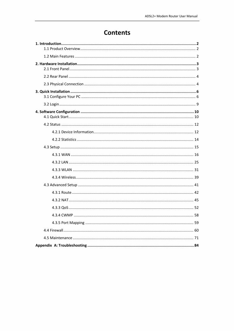
Contents
1. Introduction ....................................................................................................................... 2 1.1 Product Overview ............................................................................................................... 2
1.2 Main Features .................................................................................................................... 2
2. Hardware Installation ......................................................................................................... 3 2.1 Front Panel ......................................................................................................................... 3
2.2 Rear Panel .......................................................................................................................... 4
2.3 Physical Connection ........................................................................................................... 4
3. Quick Installation ............................................................................................................... 6 3.1 Configure Your PC .............................................................................................................. 6
3.2 Login ................................................................................................................................... 9
4. Software Configuration .................................................................................................... 10 4.1 Quick Start ........................................................................................................................ 10
4.2 Status ............................................................................................................................... 12
4.2.1 Device Information ................................................................................................ 12
4.2.2 Statistics ................................................................................................................ 14
4.3 Setup ................................................................................................................................ 15
4.3.1 WAN ...................................................................................................................... 16
4.3.2 LAN ........................................................................................................................ 25
4.3.3 WLAN .................................................................................................................... 31
4.3.4 Wireless ................................................................................................................. 39
4.3 Advanced Setup ............................................................................................................... 41
4.3.1 Route ..................................................................................................................... 42
4.3.2 NAT ........................................................................................................................ 45
4.3.3 QoS ........................................................................................................................ 52
4.3.4 CWMP ................................................................................................................... 58
4.3.5 Port Mapping ........................................................................................................ 59
4.4 Firewall ............................................................................................................................. 60
4.5 Maintenance .................................................................................................................... 71
Appendix A: Troubleshooting .............................................................................................. 84

ADSL2+ Modem Router User Manual
1
ADSL2+ Modem Router User Manual
2
1. Introduction
1.1 Product Overview
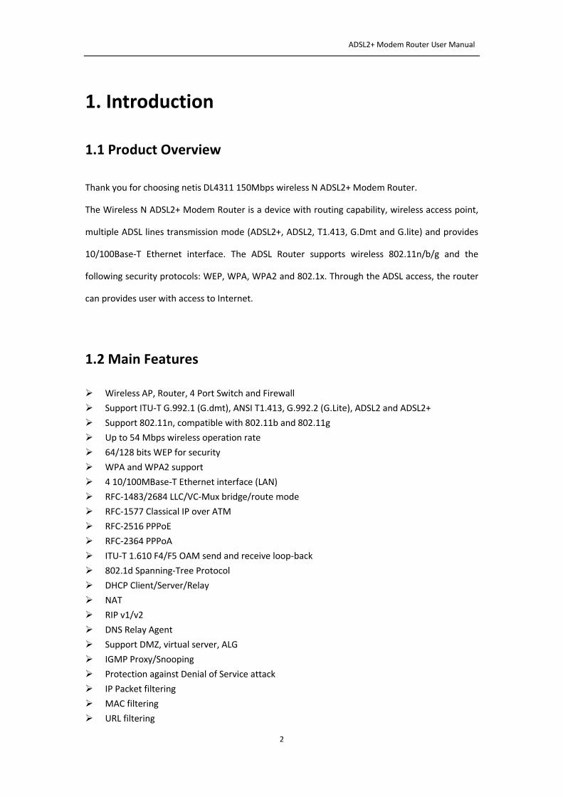
Thank you for choosing netis DL4311 150Mbps wireless N ADSL2+ Modem Router.
The Wireless N ADSL2+ Modem Router is a device with routing capability, wireless access point,
multiple ADSL lines transmission mode (ADSL2+, ADSL2, T1.413, G.Dmt and G.lite) and provides
10/100Base-T Ethernet interface. The ADSL Router supports wireless 802.11n/b/g and the
following security protocols: WEP, WPA, WPA2 and 802.1x. Through the ADSL access, the router
can provides user with access to Internet.
1.2 Main Features
Wireless AP, Router, 4 Port Switch and Firewall
Support ITU-T G.992.1 (G.dmt), ANSI T1.413, G.992.2 (G.Lite), ADSL2 and ADSL2+
Support 802.11n, compatible with 802.11b and 802.11g
Up to 54 Mbps wireless operation rate
64/128 bits WEP for security
WPA and WPA2 support
4 10/100MBase-T Ethernet interface (LAN)
RFC-1483/2684 LLC/VC-Mux bridge/route mode
RFC-1577 Classical IP over ATM
RFC-2516 PPPoE
RFC-2364 PPPoA
ITU-T 1.610 F4/F5 OAM send and receive loop-back
802.1d Spanning-Tree Protocol
DHCP Client/Server/Relay
NAT
RIP v1/v2
DNS Relay Agent
Support DMZ, virtual server, ALG
IGMP Proxy/Snooping
Protection against Denial of Service attack
IP Packet filtering
MAC filtering
URL filtering
ADSL2+ Modem Router User Manual
3
IP QoS
Dynamic DNS
UPnP support
System log support, can record the state of the router
Remote management
SNMP v1/v2/Trap
Firmware upgrade through FTP, TFTP and HTTP
Configuration backup/restore
Diagnostic tools
2. Hardware Installation
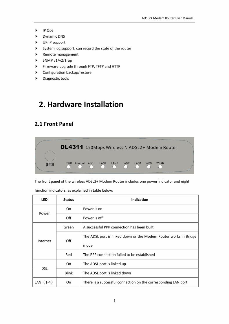
2.1 Front Panel
The front panel of the wireless ADSL2+ Modem Router includes one power indicator and eight
function indicators, as explained in table below:
LED Status Indication
Power On Power is on
Off Power is off
Internet
Green A successful PPP connection has been built
Off The ADSL port is linked down or the Modem Router works in Bridge
mode
Red The PPP connection failed to be established
DSL On The ADSL port is linked up
Blink The ADSL port is linked down
LAN(1-4) On There is a successful connection on the corresponding LAN port
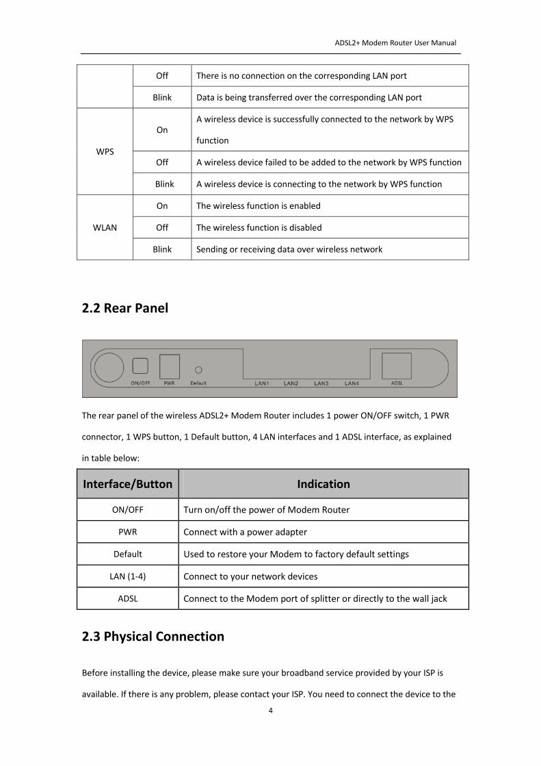
ADSL2+ Modem Router User Manual
4
Off There is no connection on the corresponding LAN port
Blink Data is being transferred over the corresponding LAN port
WPS
On A wireless device is successfully connected to the network by WPS
function
Off A wireless device failed to be added to the network by WPS function
Blink A wireless device is connecting to the network by WPS function
WLAN
On The wireless function is enabled
Off The wireless function is disabled
Blink Sending or receiving data over wireless network
2.2 Rear Panel
The rear panel of the wireless ADSL2+ Modem Router includes 1 power ON/OFF switch, 1 PWR
connector, 1 WPS button, 1 Default button, 4 LAN interfaces and 1 ADSL interface, as explained
in table below:
Interface/Button Indication
ON/OFF Turn on/off the power of Modem Router
PWR Connect with a power adapter
Default Used to restore your Modem to factory default settings
LAN (1-4) Connect to your network devices
ADSL Connect to the Modem port of splitter or directly to the wall jack
2.3 Physical Connection
Before installing the device, please make sure your broadband service provided by your ISP is
available. If there is any problem, please contact your ISP. You need to connect the device to the
ADSL2+ Modem Router User Manual
5
phone jack, the power outlet, and your computer or network. Before cable connection, turn off
the power supply and keep your hands dry. You can follow the steps below to install it.
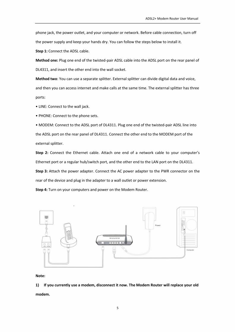
Step 1: Connect the ADSL cable.
Method one: Plug one end of the twisted-pair ADSL cable into the ADSL port on the rear panel of
DL4311, and insert the other end into the wall socket.
Method two: You can use a separate splitter. External splitter can divide digital data and voice,
and then you can access internet and make calls at the same time. The external splitter has three
ports:
• LINE: Connect to the wall jack.
• PHONE: Connect to the phone sets.
• MODEM: Connect to the ADSL port of DL4311. Plug one end of the twisted-pair ADSL line into
the ADSL port on the rear panel of DL4311. Connect the other end to the MODEM port of the
external splitter.
Step 2: Connect the Ethernet cable. Attach one end of a network cable to your computer’s
Ethernet port or a regular hub/switch port, and the other end to the LAN port on the DL4311.
Step 3: Attach the power adapter. Connect the AC power adapter to the PWR connector on the
rear of the device and plug in the adapter to a wall outlet or power extension.
Step 4: Turn on your computers and power on the Modem Router.
Note:
1) If you currently use a modem, disconnect it now. The Modem Router will replace your old
modem.
ADSL2+ Modem Router User Manual
6
2) After the physical connection, please check whether the LED indicators of the Modem
Router display normally as above describes in 2.1 section.
3. Quick Installation
3.1 Configure Your PC
After you directly connect your PC to DL4311 or a Hub/Switch which has connected to the
Modem Router, we suggest you set your computer to obtain IP address automatically.
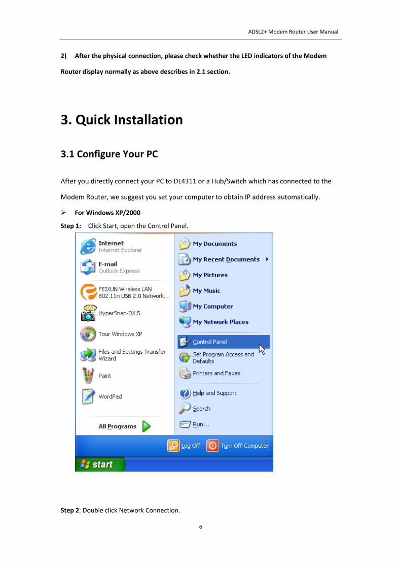
For Windows XP/2000
Step 1: Click Start, open the Control Panel.
Step 2: Double click Network Connection.
ADSL2+ Modem Router User Manual
7
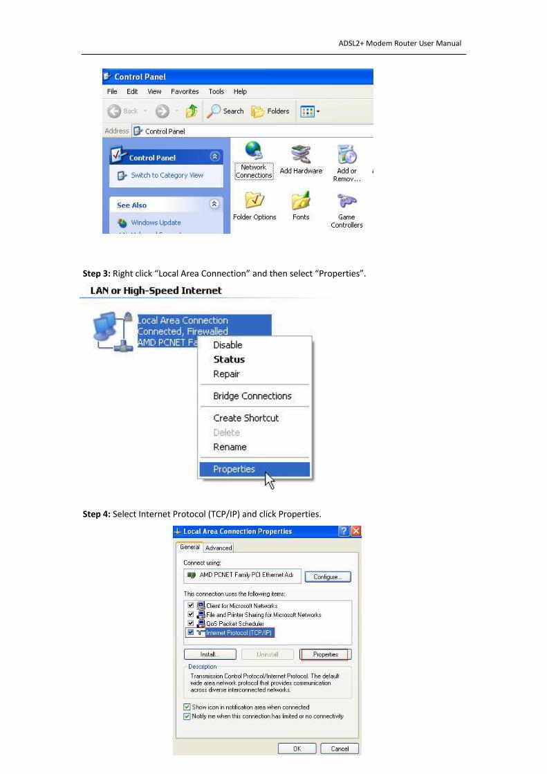
Step 3: Right click “Local Area Connection” and then select “Properties”.
Step 4: Select Internet Protocol (TCP/IP) and click Properties.
ADSL2+ Modem Router User Manual
8
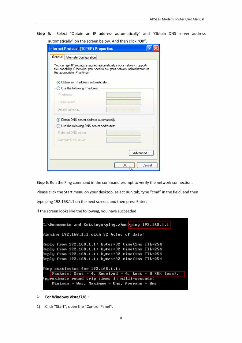
Step 5: Select “Obtain an IP address automatically” and “Obtain DNS server address
automatically” on the screen below. And then click “OK”.
Step 6: Run the Ping command in the command prompt to verify the network connection.
Please click the Start menu on your desktop, select Run tab, type “cmd” in the field, and then
type ping 192.168.1.1 on the next screen, and then press Enter.
If the screen looks like the following, you have succeeded
For Windows Vista/7/8 :
1) Click “Start”, open the “Control Panel”.
ADSL2+ Modem Router User Manual
9
2) Click “Network and Sharing Center” and then click “Manage network connection” (“Change
adapter settings” for Windows 7).
3) Right click “Local Area Connection” and then click “Properties”.
4) Select “Internet Protocol Version 4 (TCP/IPv4)” and click “Properties”.
5) Select “Obtain an IP address automatically” and “Obtain DNS server address automatically”.
Click OK.
Note: After your computer is configured successfully, go to the next section to configure the
Modem Router via web. Otherwise, refer to the section of Troubleshooting T1 to reset the
modem.
3.2 Login
After the initial configuration is done, you can login to the Web based UI. Here are the steps to
log in the UI.
Step 1: Start your web browser and enter http://192.168.1.1 in the browser address bar.
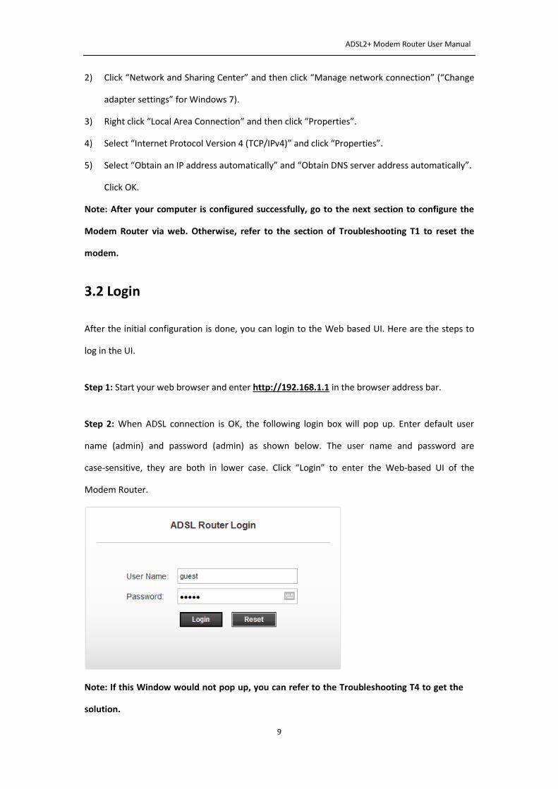
Step 2: When ADSL connection is OK, the following login box will pop up. Enter default user
name (admin) and password (admin) as shown below. The user name and password are
case-sensitive, they are both in lower case. Click “Login” to enter the Web-based UI of the
Modem Router.
Note: If this Window would not pop up, you can refer to the Troubleshooting T4 to get the
solution.
ADSL2+ Modem Router User Manual
10
4. Software Configuration
This User Manual recommends using the Quick Installation Guide for first-time installation.
For advanced users, if you want to know more about this device and make use of its functions
adequately, you will get help from this chapter to configure the advanced settings through the
Web-based UI. After your successful login, you can configure and manage the device. There
are main menus on the top of the Web-based UI, submenus will be available after you click
one of the main menus. On the center of the Web-based UI, there are the detailed
configurations or status information. To apply any settings you have altered on the page,
please click the APPLY/SAVE button.
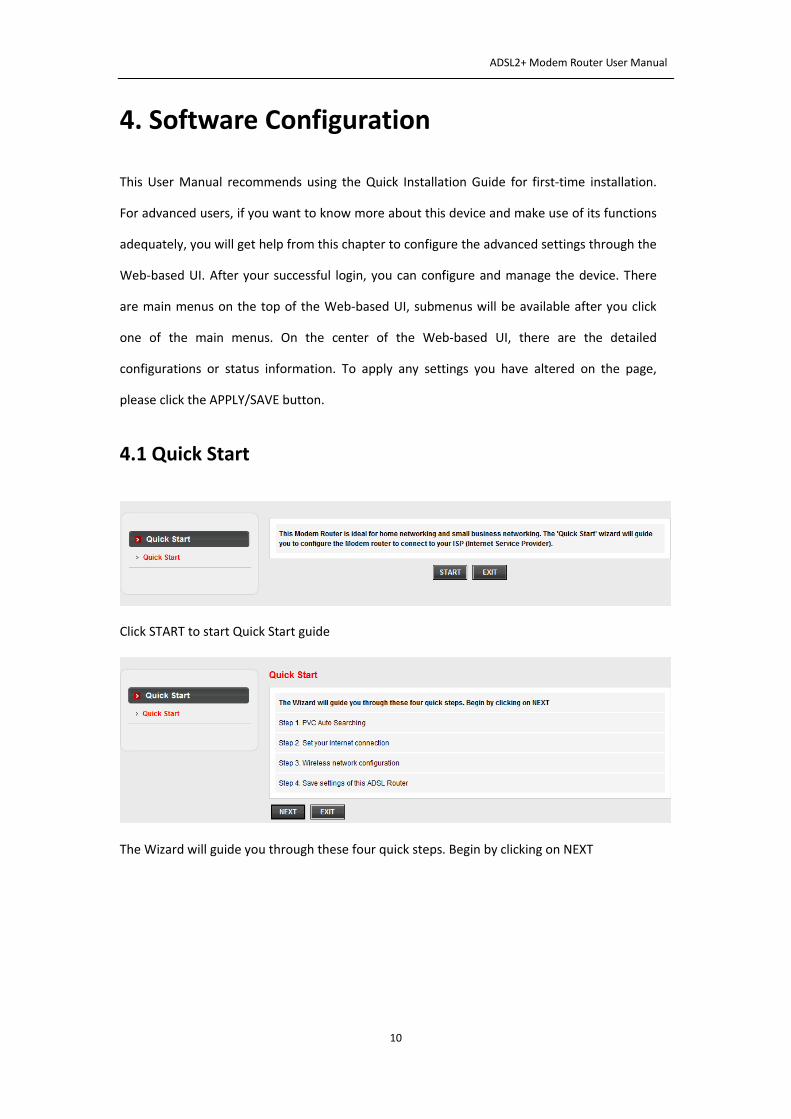
4.1 Quick Start
Click START to start Quick Start guide
The Wizard will guide you through these four quick steps. Begin by clicking on NEXT

ADSL2+ Modem Router User Manual
11
Click NO if you know the correct PVC(VPI/VCI) from your ISP, you can input the value manually.
And if you don’t know the correct value, please click OK , it will take a moment to search for
the available PVC.
After the PVC value be input or searched, please click NEXT.
Choose the correct way to access the internet which you have got from your ISP.
Enter the PPPoE/PPPoA information provided to you by your ISP, Click NEXT to continue.
ADSL2+ Modem Router User Manual
12
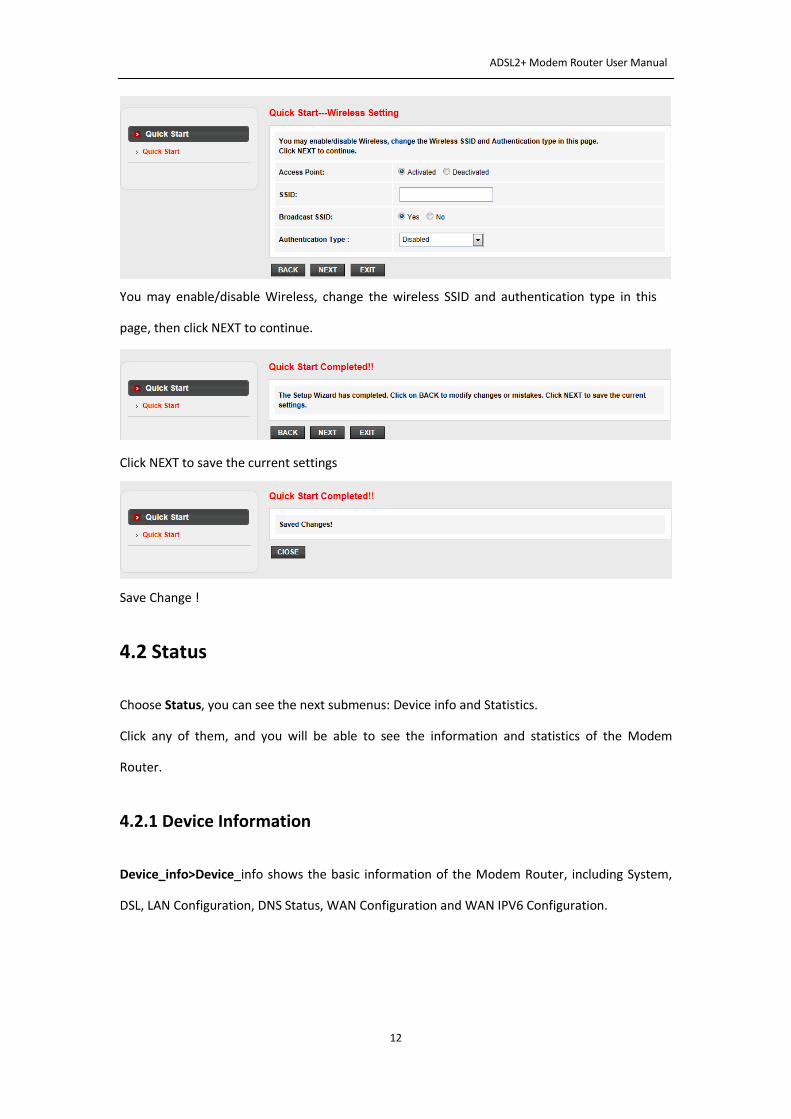
You may enable/disable Wireless, change the wireless SSID and authentication type in this
page, then click NEXT to continue.
Click NEXT to save the current settings
Save Change !
4.2 Status
Choose Status, you can see the next submenus: Device info and Statistics.
Click any of them, and you will be able to see the information and statistics of the Modem
Router.
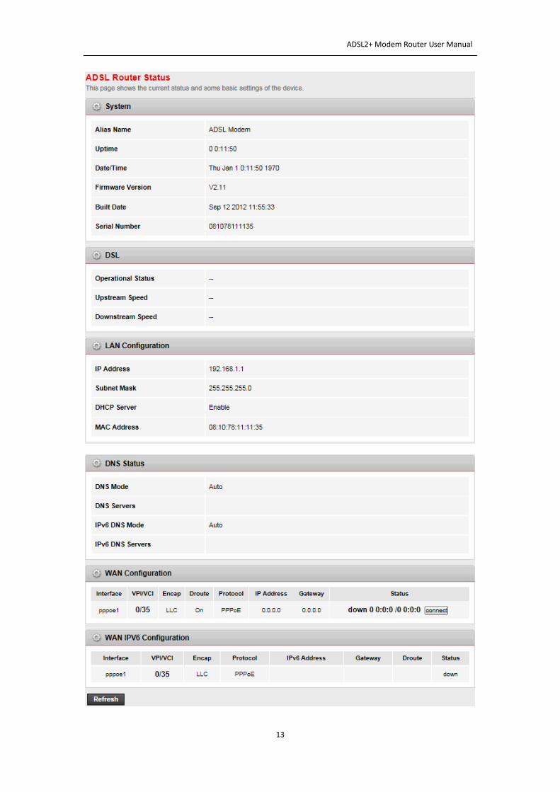
4.2.1 Device Information
Device_info>Device_info shows the basic information of the Modem Router, including System,
DSL, LAN Configuration, DNS Status, WAN Configuration and WAN IPV6 Configuration.
ADSL2+ Modem Router User Manual
13
ADSL2+ Modem Router User Manual
14
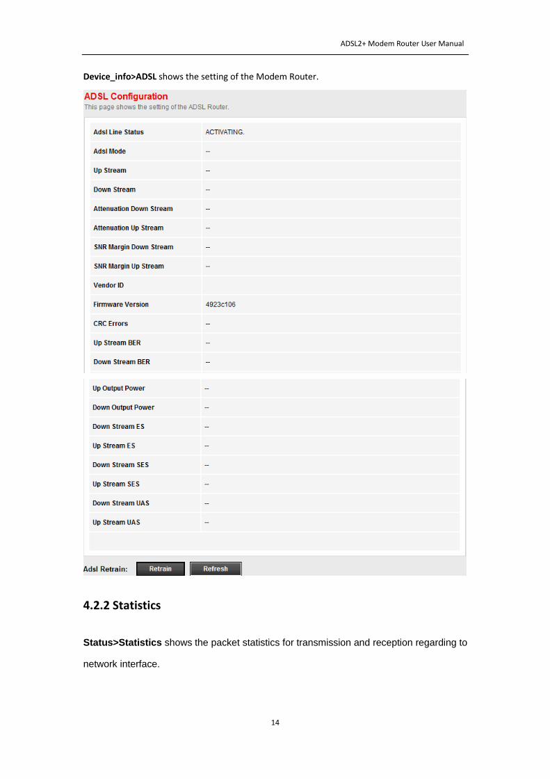
Device_info>ADSL shows the setting of the Modem Router.
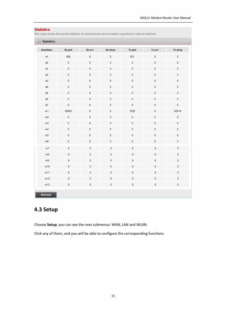
4.2.2 Statistics
Status>Statistics shows the packet statistics for transmission and reception regarding to
network interface.
ADSL2+ Modem Router User Manual
15
4.3 Setup
Choose Setup, you can see the next submenus: WAN, LAN and WLAN.
Click any of them, and you will be able to configure the corresponding functions.
ADSL2+ Modem Router User Manual
16
4.3.1 WAN
4.3.1.1 WAN-(Channel Configuration)
To enjoy the surfing, we should have the most basic configuration of the router at first. In this
chapter, you can set the basic network parameters required to access the Internet.
The router supports the following three common means to access:
Dynamic IP access: ISP (such as China Telecom) assigns IP address to users via DHCP.
Static IP access: ISP provides a static IP address to users.
PPPoE/PPPoA dial-up access(ADSL): use PPPoE/PPPoA virtual dial-up connection to the Internet.
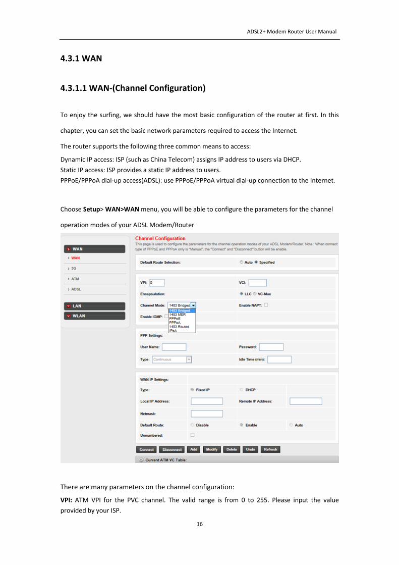
Choose Setup> WAN>WAN menu, you will be able to configure the parameters for the channel
operation modes of your ADSL Modem/Router
There are many parameters on the channel configuration:
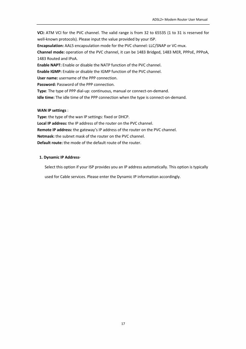
VPI: ATM VPI for the PVC channel. The valid range is from 0 to 255. Please input the value
provided by your ISP.
ADSL2+ Modem Router User Manual
17
VCI: ATM VCI for the PVC channel. The valid range is from 32 to 65535 (1 to 31 is reserved for
well-known protocols). Please input the value provided by your ISP.
Encapsulation: AAL5 encapsulation mode for the PVC channel: LLC/SNAP or VC-mux.
Channel mode: operation of the PVC channel, it can be 1483 Bridged, 1483 MER, PPPoE, PPPoA,
1483 Routed and IPoA.
Enable NAPT: Enable or disable the NATP function of the PVC channel.
Enable IGMP: Enable or disable the IGMP function of the PVC channel.
User name: username of the PPP connection.
Password: Password of the PPP connection.
Type: The type of PPP dial-up: continuous, manual or connect-on-demand.
Idle time: The idle time of the PPP connection when the type is connect-on-demand.
WAN IP settings :
Type: the type of the wan IP settings: fixed or DHCP.
Local IP address: the IP address of the router on the PVC channel.
Remote IP address: the gateway’s IP address of the router on the PVC channel.
Netmask: the subnet mask of the router on the PVC channel.
Default route: the mode of the default route of the router.
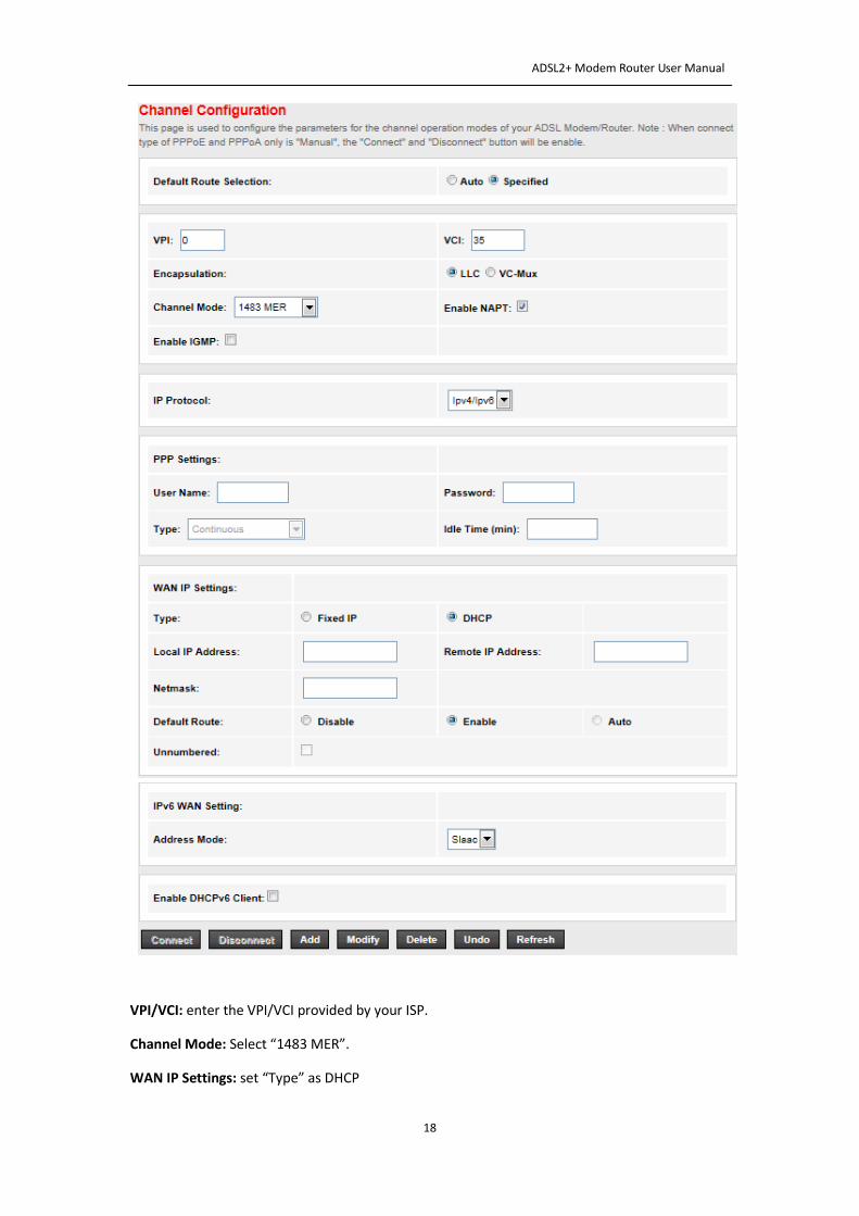
1. Dynamic IP Address·
Select this option if your ISP provides you an IP address automatically. This option is typically
used for Cable services. Please enter the Dynamic IP information accordingly.
ADSL2+ Modem Router User Manual
18
VPI/VCI: enter the VPI/VCI provided by your ISP.
Channel Mode: Select “1483 MER”.
WAN IP Settings: set “Type” as DHCP
ADSL2+ Modem Router User Manual
19
Default Route: Enable
Then click the “Add” button to setup a new connection,when the connection is setup, you can
see the router will obtain an IP address.
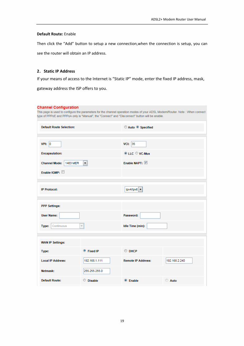
2.Static IP Address
If your means of access to the Internet is “Static IP” mode, enter the fixed IP address, mask,
gateway address the ISP offers to you.
ADSL2+ Modem Router User Manual
20
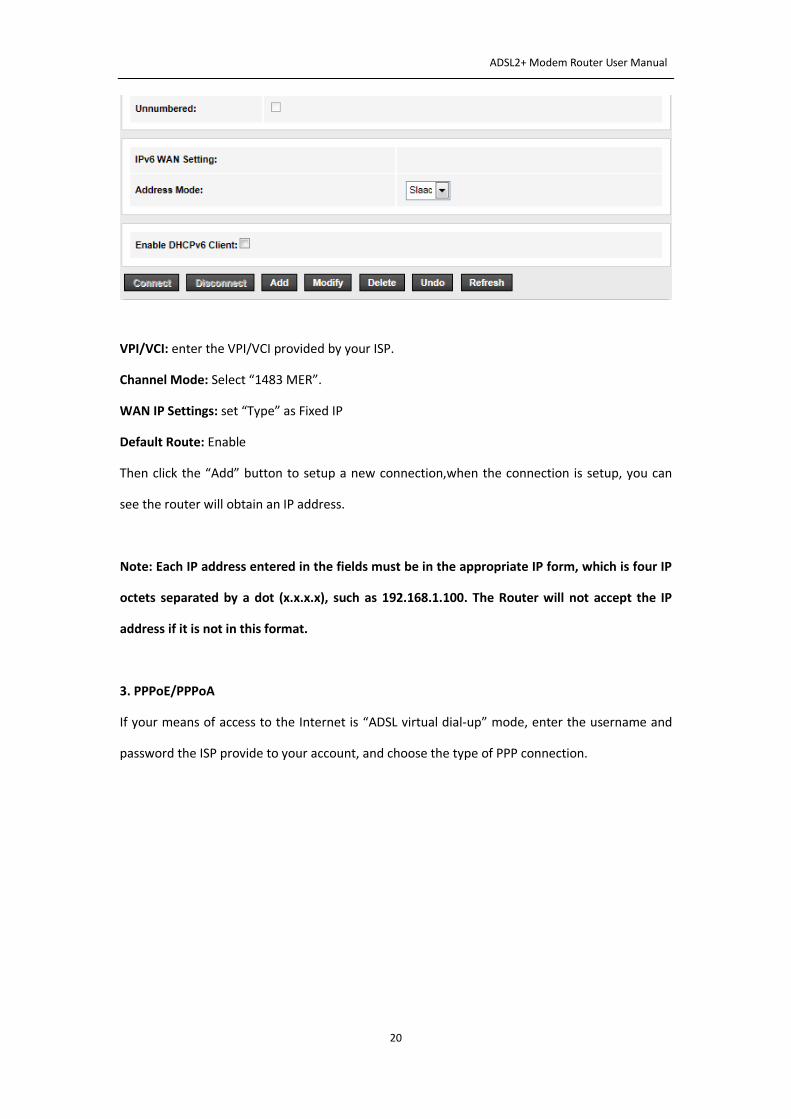
VPI/VCI: enter the VPI/VCI provided by your ISP.
Channel Mode: Select “1483 MER”.
WAN IP Settings: set “Type” as Fixed IP
Default Route: Enable
Then click the “Add” button to setup a new connection,when the connection is setup, you can
see the router will obtain an IP address.
Note: Each IP address entered in the fields must be in the appropriate IP form, which is four IP
octets separated by a dot (x.x.x.x), such as 192.168.1.100. The Router will not accept the IP
address if it is not in this format.
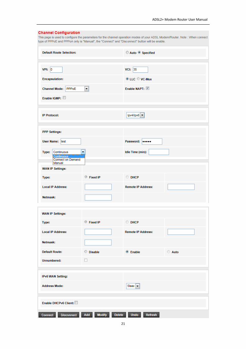
3. PPPoE/PPPoA
If your means of access to the Internet is “ADSL virtual dial-up” mode, enter the username and
password the ISP provide to your account, and choose the type of PPP connection.
ADSL2+ Modem Router User Manual
21
ADSL2+ Modem Router User Manual
22
VPI/VCI: enter the VPI/VCI provided by your ISP.
Channel Mode: Select “PPPoE” or “PPPoA”.
PPP Settings: Select “Continuous” or “Connect on demand” or “Manual”. (If the type is “connect
on demand”, you should also set the Idle Time.)
Encapsulation: For both PPPoA/PPPoE connection, you need to specify the type of Multiplexing,
either LLC or VC -Mux.
Default Route: Enable
Then click the “Add” button to setup a new connection, when the connection is setup, you can
show the router will obtain an IP address after the dial-up.
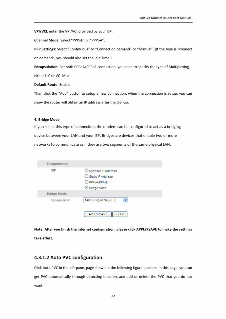
4. Bridge Mode
If you select this type of connection, the modem can be configured to act as a bridging
device between your LAN and your ISP. Bridges are devices that enable two or more
networks to communicate as if they are two segments of the same physical LAN.
Note: After you finish the internet configuration, please click APPLY/SAVE to make the settings
take effect.
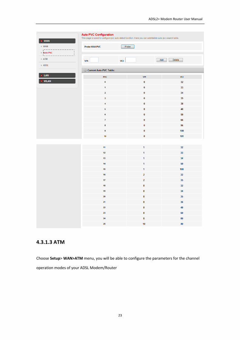
4.3.1.2 Aoto PVC configuration
Click Auto PVC in the left pane, page shown in the following figure appears. In this page, you can
get PVC automatically through detecting function, and add or delete the PVC that you do not
want.
ADSL2+ Modem Router User Manual
23
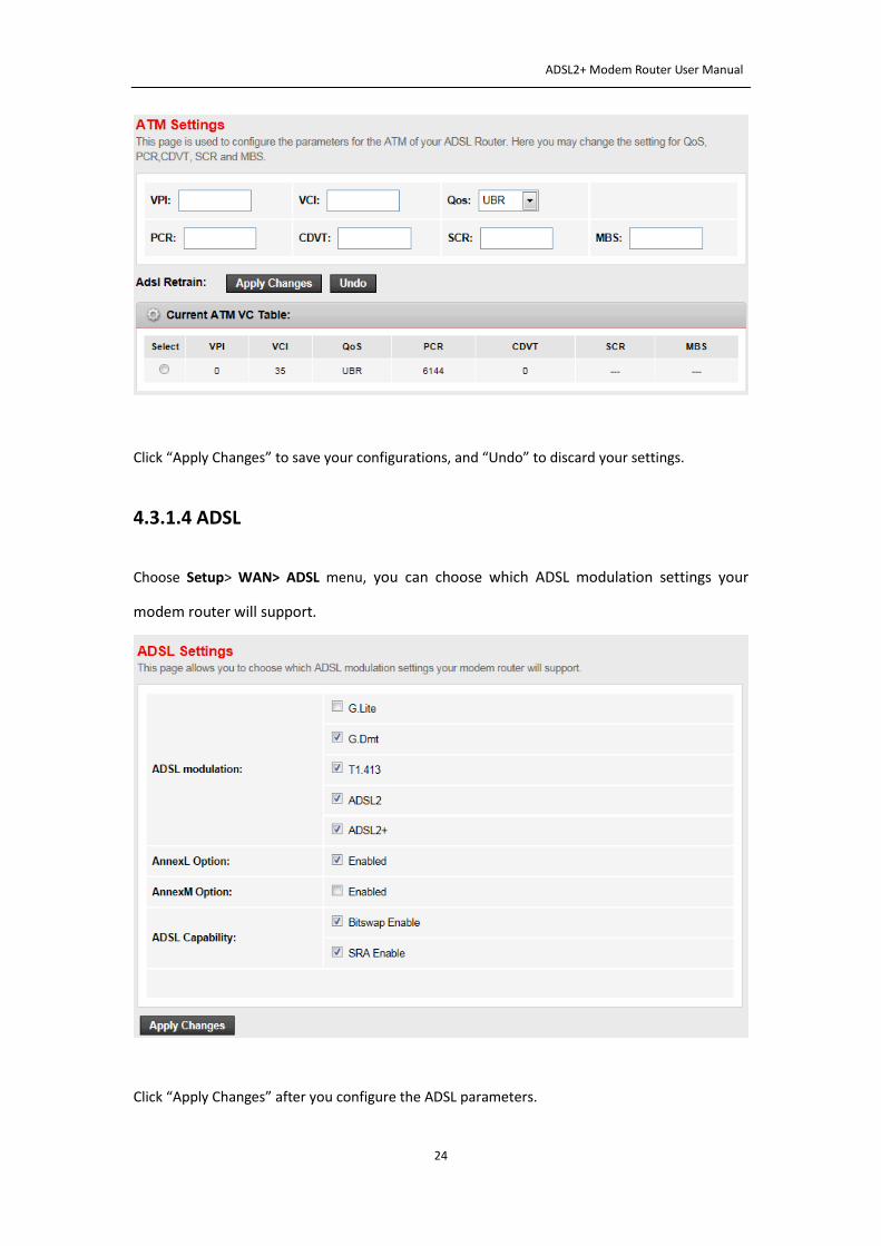
4.3.1.3 ATM
Choose Setup> WAN>ATM menu, you will be able to configure the parameters for the channel
operation modes of your ADSL Modem/Router
ADSL2+ Modem Router User Manual
24
Click “Apply Changes” to save your configurations, and “Undo” to discard your settings.
4.3.1.4 ADSL
Choose Setup> WAN> ADSL menu, you can choose which ADSL modulation settings your
modem router will support.
Click “Apply Changes” after you configure the ADSL parameters.
ADSL2+ Modem Router User Manual
25
4.3.2 LAN
Choose Setup> LAN menu, and you will see the sub-manuals including LAN, DHCP, DHCP
Statistics and LAN IPv6. Please configure the parameters for LAN ports according to the
descriptions below.
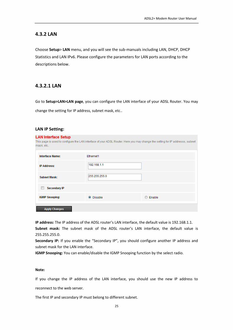
4.3.2.1 LAN
Go to Setup>LAN>LAN page, you can configure the LAN interface of your ADSL Router. You may
change the setting for IP address, subnet mask, etc..
LAN IP Setting:
IP address: The IP address of the ADSL router’s LAN interface, the default value is 192.168.1.1.
Subnet mask: The subnet mask of the ADSL router’s LAN interface, the default value is
255.255.255.0.
Secondary IP: If you enable the “Secondary IP”, you should configure another IP address and
subnet mask for the LAN interface.
IGMP Snooping: You can enable/disable the IGMP Snooping function by the select radio.
Note:
If you change the IP address of the LAN interface, you should use the new IP address to
reconnect to the web server.
The first IP and secondary IP must belong to different subnet.
ADSL2+ Modem Router User Manual
26
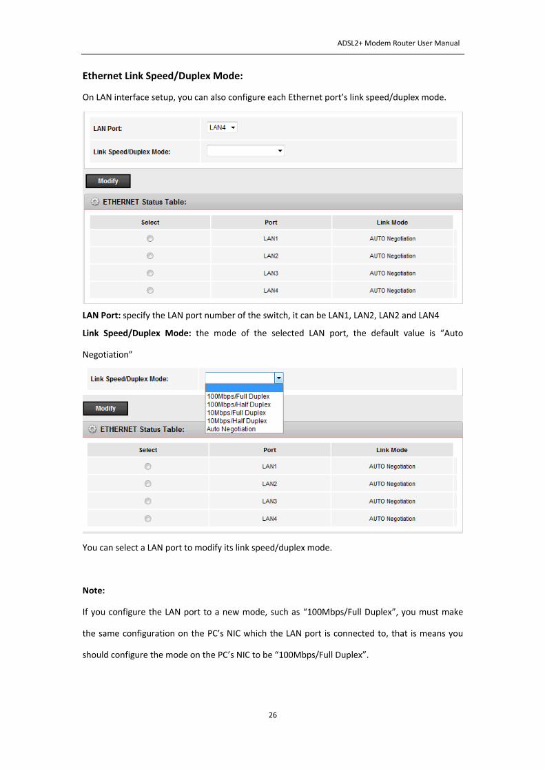
Ethernet Link Speed/Duplex Mode:
On LAN interface setup, you can also configure each Ethernet port’s link speed/duplex mode.
LAN Port: specify the LAN port number of the switch, it can be LAN1, LAN2, LAN2 and LAN4
Link Speed/Duplex Mode: the mode of the selected LAN port, the default value is “Auto
Negotiation”
You can select a LAN port to modify its link speed/duplex mode.
Note:
If you configure the LAN port to a new mode, such as “100Mbps/Full Duplex”, you must make
the same configuration on the PC’s NIC which the LAN port is connected to, that is means you
should configure the mode on the PC’s NIC to be “100Mbps/Full Duplex”.
ADSL2+ Modem Router User Manual
27
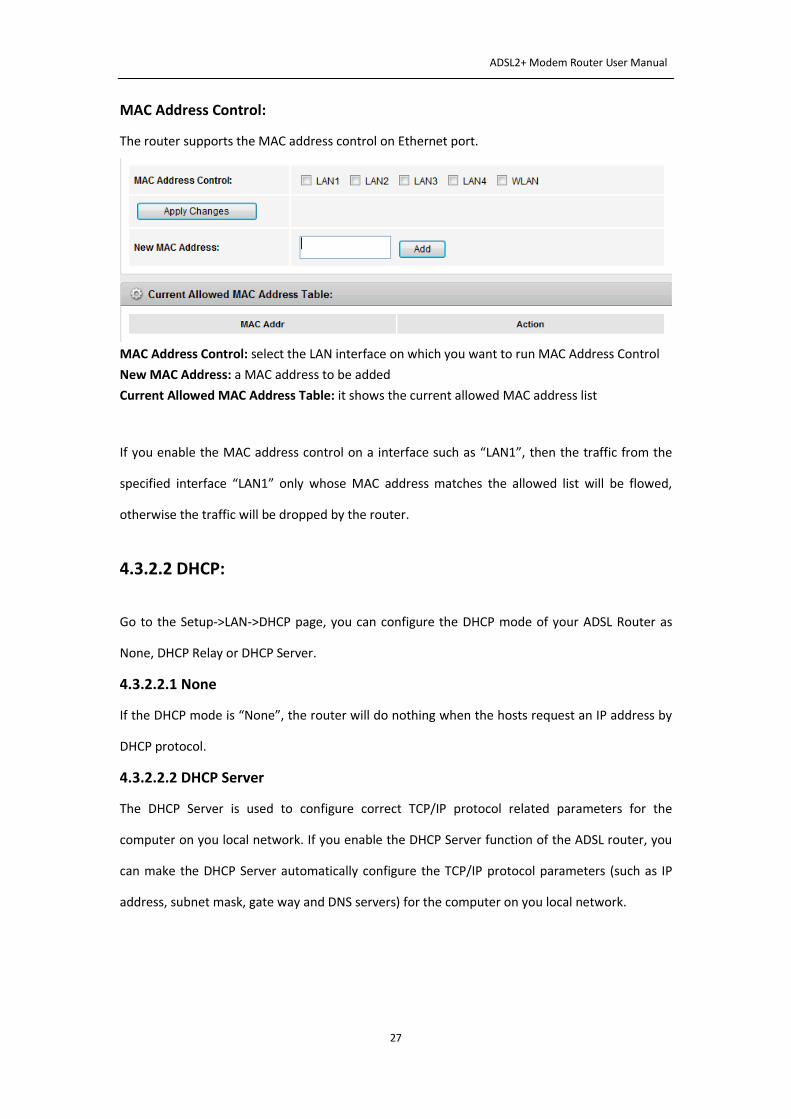
MAC Address Control:
The router supports the MAC address control on Ethernet port.
MAC Address Control: select the LAN interface on which you want to run MAC Address Control
New MAC Address: a MAC address to be added
Current Allowed MAC Address Table: it shows the current allowed MAC address list
If you enable the MAC address control on a interface such as “LAN1”, then the traffic from the
specified interface “LAN1” only whose MAC address matches the allowed list will be flowed,
otherwise the traffic will be dropped by the router.
4.3.2.2 DHCP:
Go to the Setup->LAN->DHCP page, you can configure the DHCP mode of your ADSL Router as
None, DHCP Relay or DHCP Server.
4.3.2.2.1 None
If the DHCP mode is “None”, the router will do nothing when the hosts request an IP address by
DHCP protocol.
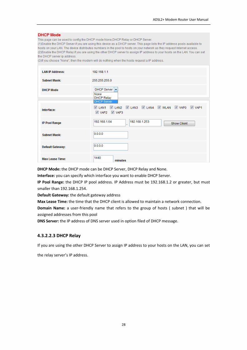
4.3.2.2.2 DHCP Server
The DHCP Server is used to configure correct TCP/IP protocol related parameters for the
computer on you local network. If you enable the DHCP Server function of the ADSL router, you
can make the DHCP Server automatically configure the TCP/IP protocol parameters (such as IP
address, subnet mask, gate way and DNS servers) for the computer on you local network.
ADSL2+ Modem Router User Manual
28
DHCP Mode: the DHCP mode can be DHCP Server, DHCP Relay and None.
Interface: you can specify which interface you want to enable DHCP Server.
IP Pool Range: the DHCP IP pool address. IP Address must be 192.168.1.2 or greater, but must
smaller than 192.168.1.254.
Default Gateway: the default gateway address
Max Lease Time: the time that the DHCP client is allowed to maintain a network connection.
Domain Name: a user-friendly name that refers to the group of hosts ( subnet ) that will be
assigned addresses from this pool
DNS Server: the IP address of DNS server used in option filed of DHCP message.
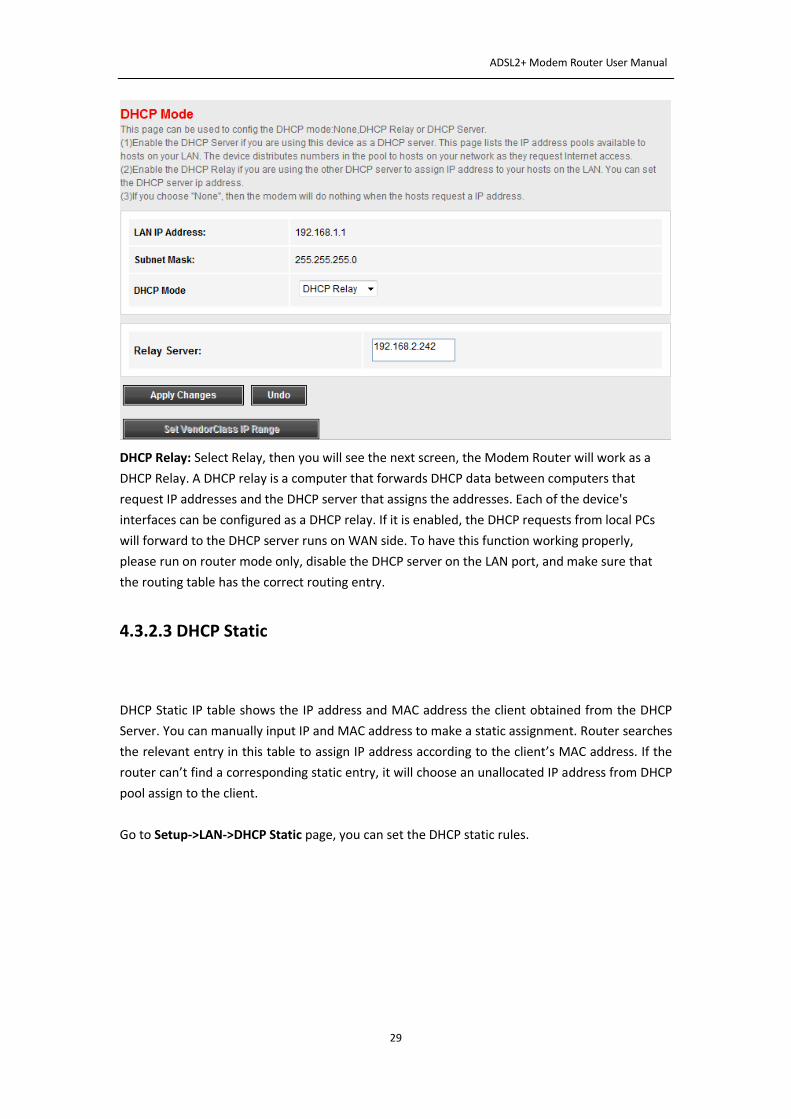
4.3.2.2.3 DHCP Relay
If you are using the other DHCP Server to assign IP address to your hosts on the LAN, you can set
the relay server’s IP address.
ADSL2+ Modem Router User Manual
29
DHCP Relay: Select Relay, then you will see the next screen, the Modem Router will work as a
DHCP Relay. A DHCP relay is a computer that forwards DHCP data between computers that
request IP addresses and the DHCP server that assigns the addresses. Each of the device's
interfaces can be configured as a DHCP relay. If it is enabled, the DHCP requests from local PCs
will forward to the DHCP server runs on WAN side. To have this function working properly,
please run on router mode only, disable the DHCP server on the LAN port, and make sure that
the routing table has the correct routing entry.
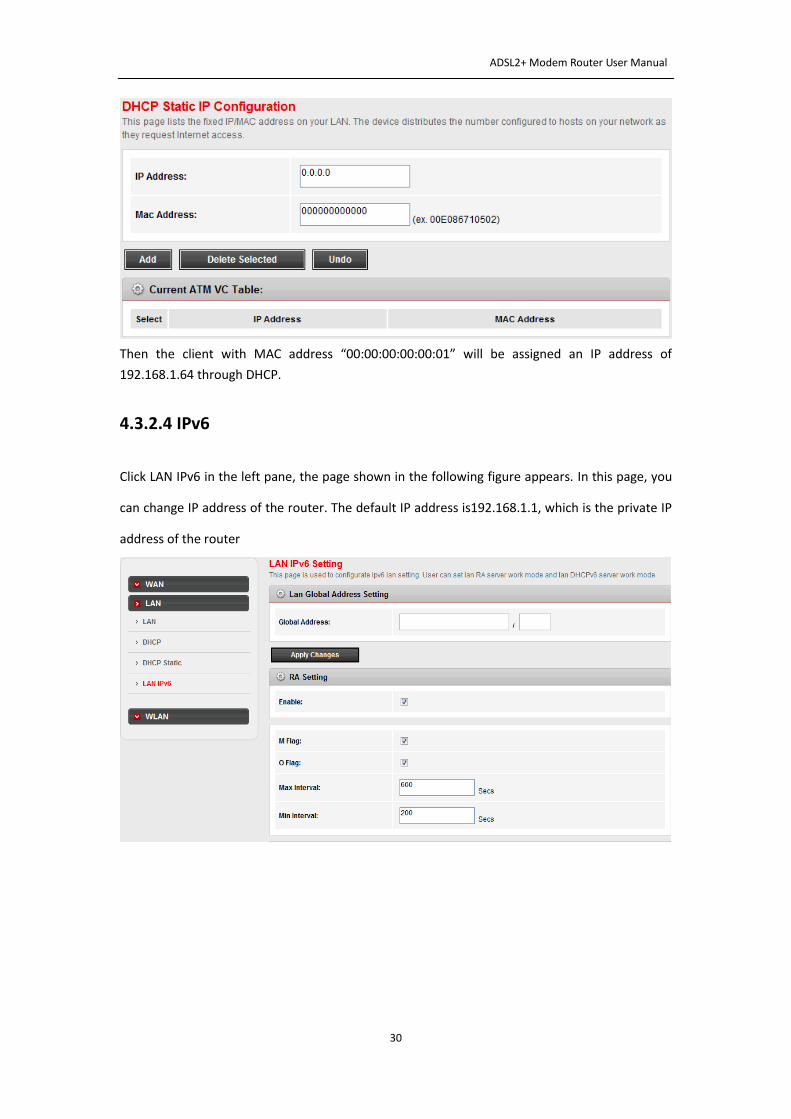
4.3.2.3 DHCP Static
DHCP Static IP table shows the IP address and MAC address the client obtained from the DHCP
Server. You can manually input IP and MAC address to make a static assignment. Router searches
the relevant entry in this table to assign IP address according to the client’s MAC address. If the
router can’t find a corresponding static entry, it will choose an unallocated IP address from DHCP
pool assign to the client.
Go to Setup->LAN->DHCP Static page, you can set the DHCP static rules.
ADSL2+ Modem Router User Manual
30
Then the client with MAC address “00:00:00:00:00:01” will be assigned an IP address of
192.168.1.64 through DHCP.
4.3.2.4 IPv6
Click LAN IPv6 in the left pane, the page shown in the following figure appears. In this page, you
can change IP address of the router. The default IP address is192.168.1.1, which is the private IP
address of the router
ADSL2+ Modem Router User Manual
31
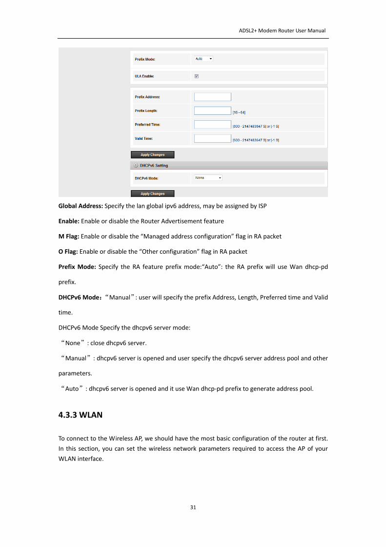
Global Address: Specify the lan global ipv6 address, may be assigned by ISP
Enable: Enable or disable the Router Advertisement feature
M Flag: Enable or disable the “Managed address configuration” flag in RA packet
O Flag: Enable or disable the “Other configuration” flag in RA packet
Prefix Mode: Specify the RA feature prefix mode:“Auto”: the RA prefix will use Wan dhcp-pd
prefix.
DHCPv6 Mode:“Manual”: user will specify the prefix Address, Length, Preferred time and Valid
time.
DHCPv6 Mode Specify the dhcpv6 server mode:
“None”: close dhcpv6 server.
“Manual”: dhcpv6 server is opened and user specify the dhcpv6 server address pool and other
parameters.
“Auto”: dhcpv6 server is opened and it use Wan dhcp-pd prefix to generate address pool.
4.3.3 WLAN
To connect to the Wireless AP, we should have the most basic configuration of the router at first.
In this section, you can set the wireless network parameters required to access the AP of your
WLAN interface.
ADSL2+ Modem Router User Manual
32
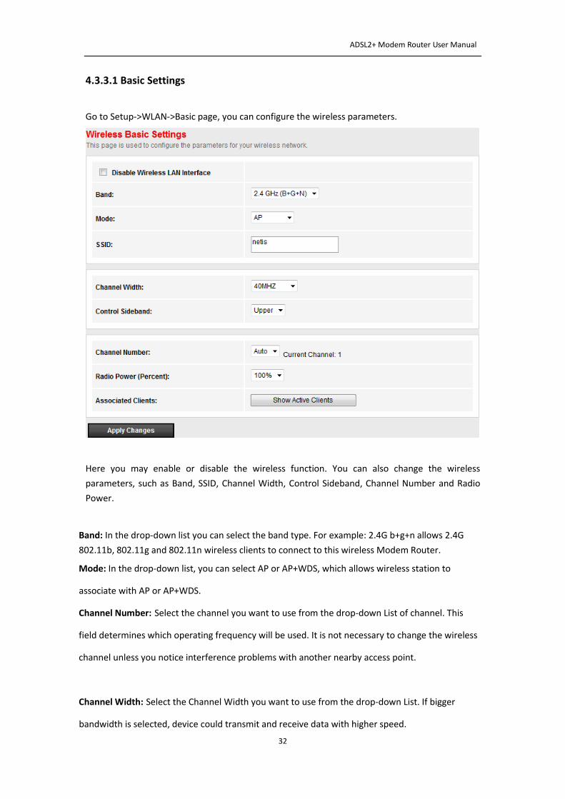
4.3.3.1 Basic Settings
Go to Setup->WLAN->Basic page, you can configure the wireless parameters.
Here you may enable or disable the wireless function. You can also change the wireless
parameters, such as Band, SSID, Channel Width, Control Sideband, Channel Number and Radio
Power.
Band: In the drop-down list you can select the band type. For example: 2.4G b+g+n allows 2.4G
802.11b, 802.11g and 802.11n wireless clients to connect to this wireless Modem Router.
Mode: In the drop-down list, you can select AP or AP+WDS, which allows wireless station to
associate with AP or AP+WDS.
Channel Number: Select the channel you want to use from the drop-down List of channel. This
field determines which operating frequency will be used. It is not necessary to change the wireless
channel unless you notice interference problems with another nearby access point.
Channel Width: Select the Channel Width you want to use from the drop-down List. If bigger
bandwidth is selected, device could transmit and receive data with higher speed.
ADSL2+ Modem Router User Manual
33
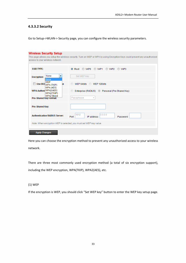
4.3.3.2 Security
Go to Setup->WLAN-> Security page, you can configure the wireless security parameters.
Here you can choose the encryption method to prevent any unauthorized access to your wireless
network.
There are three most commonly used encryption method (a total of six encryption support),
including the WEP encryption, WPA(TKIP), WPA2(AES), etc.
(1) WEP
If the encryption is WEP, you should click “Set WEP key” button to enter the WEP key setup page.
ADSL2+ Modem Router User Manual
34
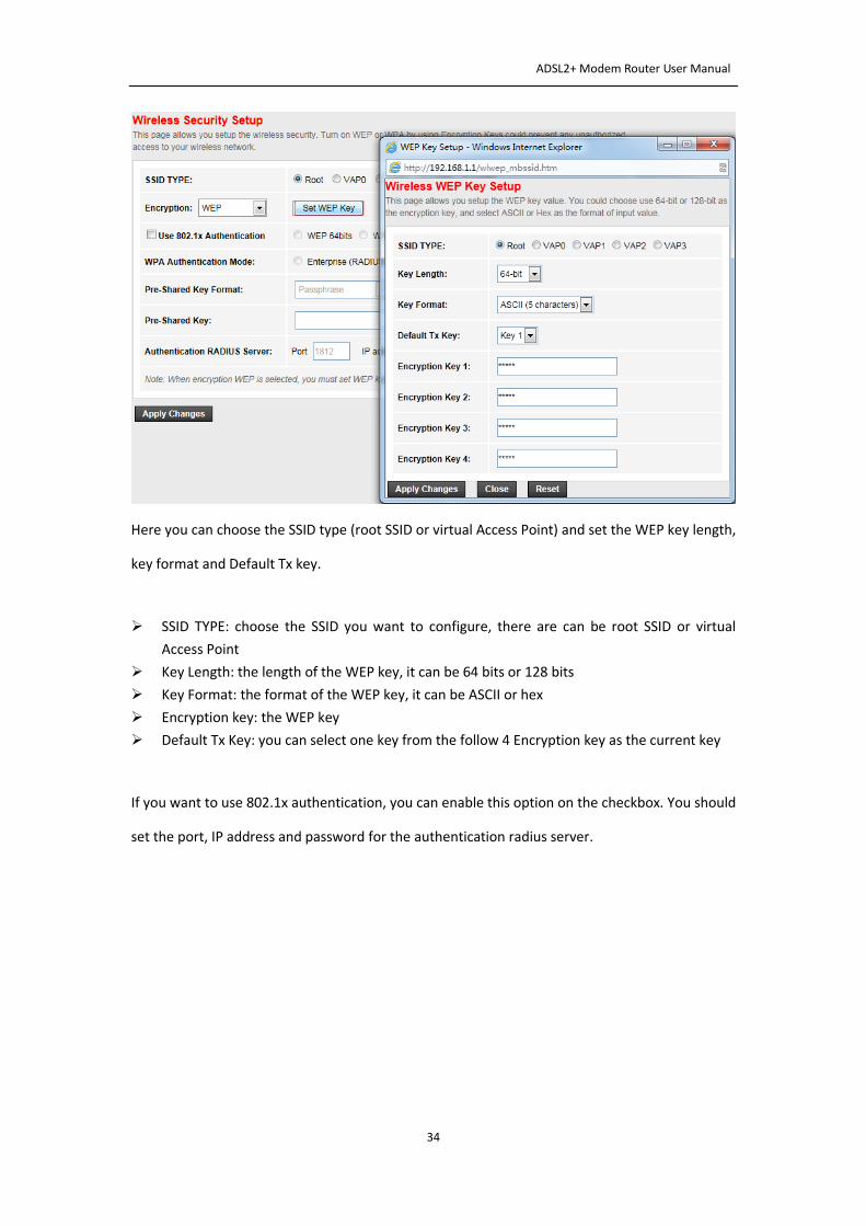
Here you can choose the SSID type (root SSID or virtual Access Point) and set the WEP key length,
key format and Default Tx key.
SSID TYPE: choose the SSID you want to configure, there are can be root SSID or virtual
Access Point
Key Length: the length of the WEP key, it can be 64 bits or 128 bits
Key Format: the format of the WEP key, it can be ASCII or hex
Encryption key: the WEP key
Default Tx Key: you can select one key from the follow 4 Encryption key as the current key
If you want to use 802.1x authentication, you can enable this option on the checkbox. You should
set the port, IP address and password for the authentication radius server.
ADSL2+ Modem Router User Manual
35
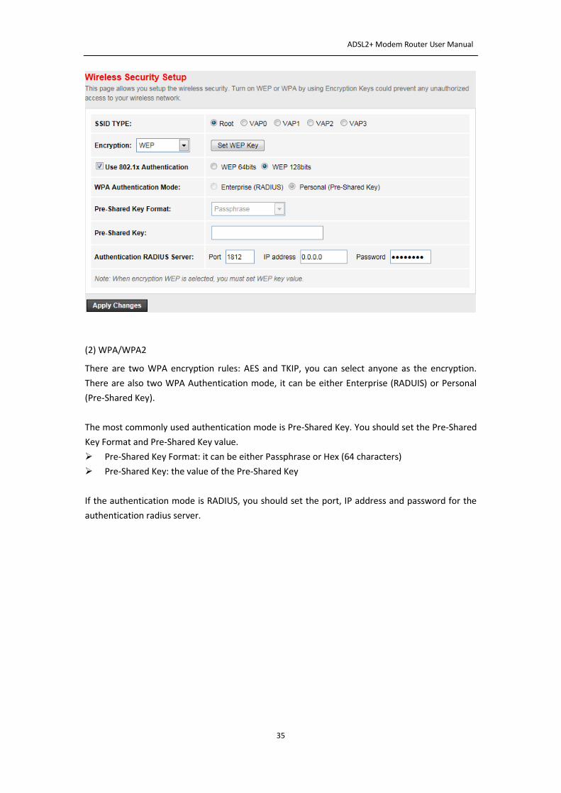
(2) WPA/WPA2
There are two WPA encryption rules: AES and TKIP, you can select anyone as the encryption.
There are also two WPA Authentication mode, it can be either Enterprise (RADUIS) or Personal
(Pre-Shared Key).
The most commonly used authentication mode is Pre-Shared Key. You should set the Pre-Shared
Key Format and Pre-Shared Key value.
Pre-Shared Key Format: it can be either Passphrase or Hex (64 characters)
Pre-Shared Key: the value of the Pre-Shared Key
If the authentication mode is RADIUS, you should set the port, IP address and password for the
authentication radius server.
ADSL2+ Modem Router User Manual
36
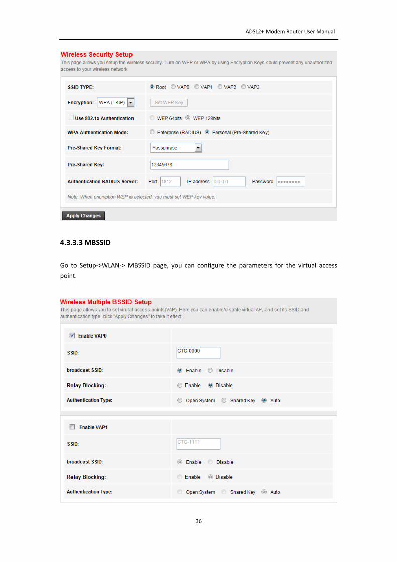
4.3.3.3 MBSSID
Go to Setup->WLAN-> MBSSID page, you can configure the parameters for the virtual access
point.
ADSL2+ Modem Router User Manual
37
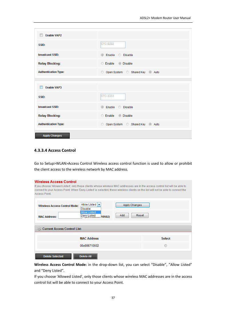
4.3.3.4 Access Control
Go to Setup>WLAN>Access Control Wireless access control function is used to allow or prohibit
the client access to the wireless network by MAC address.
Wireless Access Control Mode: in the drop-down list, you can select “Disable”, ”Allow Listed”
and “Deny Listed”.
If you choose 'Allowed Listed', only those clients whose wireless MAC addresses are in the access
control list will be able to connect to your Access Point.
ADSL2+ Modem Router User Manual
38
When 'Deny Listed' is selected, these wireless clients on the list will not be able to connect the
Access Point.
MAC Address: input the MAC address in the blank, and click “Add” to add it to “Current Access
Control List”
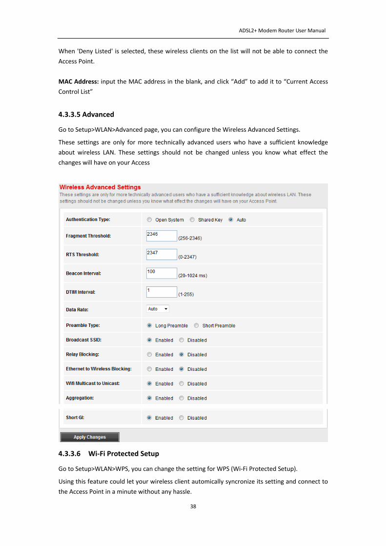
4.3.3.5 Advanced
Go to Setup>WLAN>Advanced page, you can configure the Wireless Advanced Settings.
These settings are only for more technically advanced users who have a sufficient knowledge
about wireless LAN. These settings should not be changed unless you know what effect the
changes will have on your Access
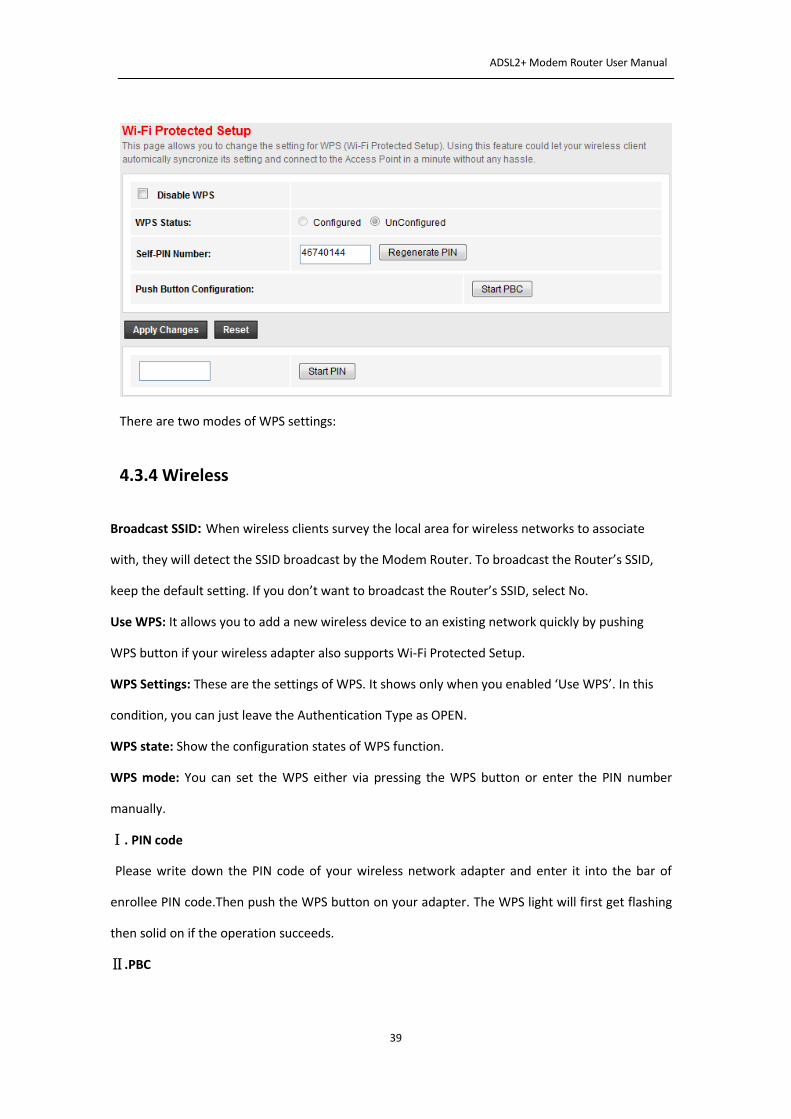
4.3.3.6 Wi-Fi Protected Setup
Go to Setup>WLAN>WPS, you can change the setting for WPS (Wi-Fi Protected Setup).
Using this feature could let your wireless client automically syncronize its setting and connect to
the Access Point in a minute without any hassle.
ADSL2+ Modem Router User Manual
39
There are two modes of WPS settings:
4.3.4 Wireless
Broadcast SSID: When wireless clients survey the local area for wireless networks to associate
with, they will detect the SSID broadcast by the Modem Router. To broadcast the Router’s SSID,
keep the default setting. If you don’t want to broadcast the Router’s SSID, select No.
Use WPS: It allows you to add a new wireless device to an existing network quickly by pushing
WPS button if your wireless adapter also supports Wi-Fi Protected Setup.
WPS Settings: These are the settings of WPS. It shows only when you enabled ‘Use WPS’. In this
condition, you can just leave the Authentication Type as OPEN.
WPS state: Show the configuration states of WPS function.
WPS mode: You can set the WPS either via pressing the WPS button or enter the PIN number
manually.
Ⅰ. PIN code
Please write down the PIN code of your wireless network adapter and enter it into the bar of
enrollee PIN code.Then push the WPS button on your adapter. The WPS light will first get flashing
then solid on if the operation succeeds.
Ⅱ.PBC
ADSL2+ Modem Router User Manual
40
First, push the button of WPS on this Modem Router, release it. Then turn to your wireless
network adapter, push the WPS button and release it. Wait a moment, the WPS will become
flashing then finally get solid on if the connection is successful.
Note:
1) This feature is available only when OPEN, WPA-PSK, WPA2-PSK or WPA/WPA2-PSK mode is
configured.
2) To build a successful connection by WPS, you should also do the corresponding configuration
of the new device for WPS function meanwhile.
WPS progress: Idle or In progress, shows the progress of WPS
Authentication Type: Select an authentication type from the drop-down list, which allows you to
configure security features of the wireless LAN interface. Options available are: Disabled,
WEP-64Bits, WEP-128Bits, WPA-PSK, and WPA2-PSK.
Ⅰ. WEP-64 Bits:
To configure WEP-64Bits settings, select the WEP-64Bits option from the drop-down list. The menu
will change to offer the appropriate settings. WPA-64Bits is a data privacy mechanism based on a
64-bit shared key algorithm, as described in the IEEE 802.11g standard.
Ⅱ.WEP-128 Bits
Select WEP-128 Bits, the menu will change to offer the appropriate settings. 128-bit is stronger
than 64-bit.
Ⅲ. WPA-PSK
To configure WPA-PSK settings, select the WPA-PSK option from the drop-down list. The menu will
change to offer the appropriate settings. WPA-PSK requires a shared key and does not use a
separate server for authentication. PSK keys can be ASCII or Hex type.
Ⅳ. WPA2-PSK
To configure WPA2-PSK settings, select the WPA2-PSK option from the drop-down list. The menu
will change to offer the appropriate settings. WPA2-PSK requires a shared key and does not use a
separate server for authentication. PSK keys can be ASCII or Hex type.
Encryption: Select the encryption you want to use: Automatic, TKIP or AES (AES is an encryption
method stronger than TKIP).
• TKIP (Temporal Key Integrity Protocol): A wireless encryption protocol that provides dynamic
ADSL2+ Modem Router User Manual
41
encryption keys for each packet transmitted.
• AES (Advanced Encryption Standard): A security method that uses symmetric 128-bit blocks data
encryption.
Pre-Shared Key: Enter the key shared by the Modem Router and your other network devices. It
must be 8-63 ASCII characters or 64 Hexadecimal digits.
Wireless MAC Address Filter: Wireless access can be filtered by using the MAC addresses of the
wireless devices transmitting within your network’s radius. To filter wireless clients by MAC
Address, either deny or allow access. If you do not wish to filter users by MAC Address, select
Deactivated.
Active: Used to enable or disable this wireless Mac filter function.
Action: Choose Allow or Deny to allow or block wireless access from the devices listed on the
screen.
Mac Address: Enter the MAC Address you wish to filter in the field.
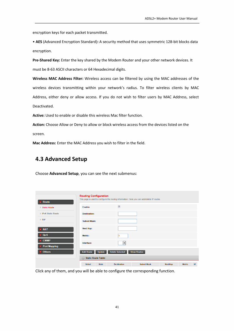
4.3 Advanced Setup
Choose Advanced Setup, you can see the next submenus:
Click any of them, and you will be able to configure the corresponding function.
ADSL2+ Modem Router User Manual
42
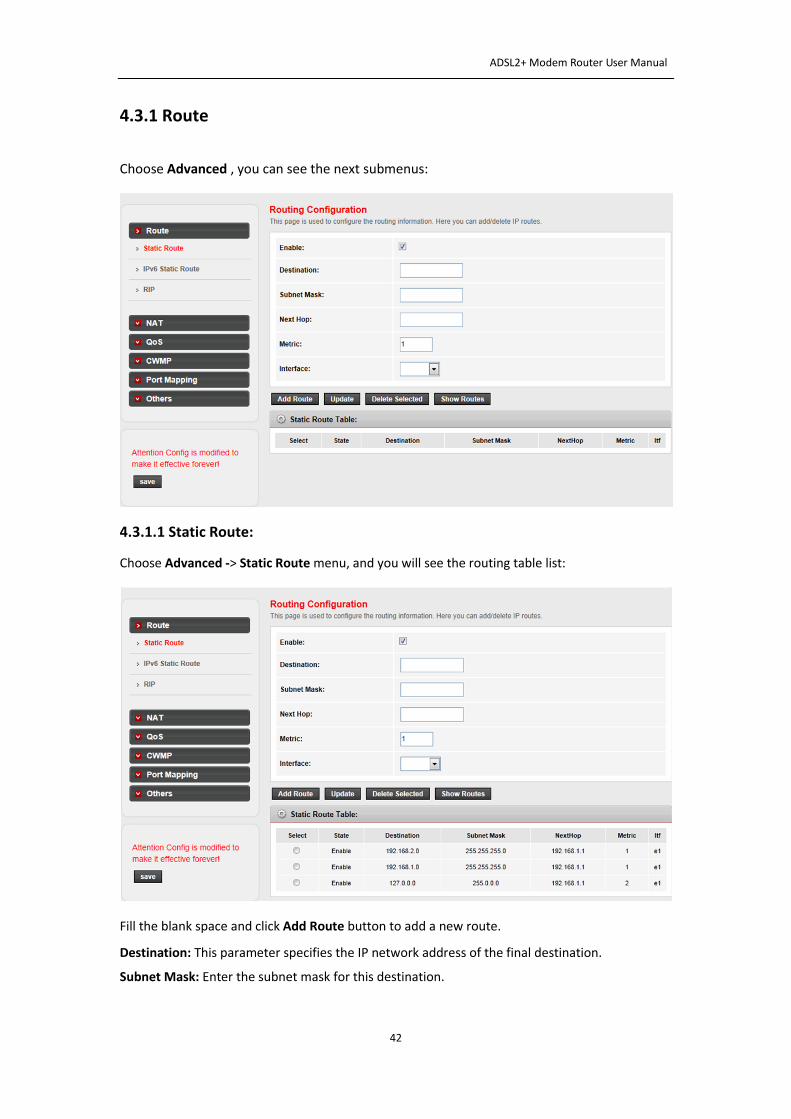
4.3.1 Route
Choose Advanced , you can see the next submenus:
4.3.1.1 Static Route:
Choose Advanced -> Static Route menu, and you will see the routing table list:
Fill the blank space and click Add Route button to add a new route.
Destination: This parameter specifies the IP network address of the final destination.
Subnet Mask: Enter the subnet mask for this destination.
ADSL2+ Modem Router User Manual
43
Next hop: Enter the IP address of the gateway. The gateway is an immediate neighbor of your
ADSL Router that will forward the packet to the destination. On the LAN, the gateway must be a
router on the same segment as your Router; over Internet (WAN), the gateway must be the IP
address of one of the remote nodes.
Metric: Metric represents the cost of transmission for routing purposes. IP Routing uses hop
count as the measurement of cost, with a minimum of 1 for directly connected networks. Enter a
number that approximates the cost for this link. The number need not to be precise, but it must
between 1 and 15. In practice, 2 or 3 is usually a good number.
Interface: the WAN interface to which a static route is to be applied.
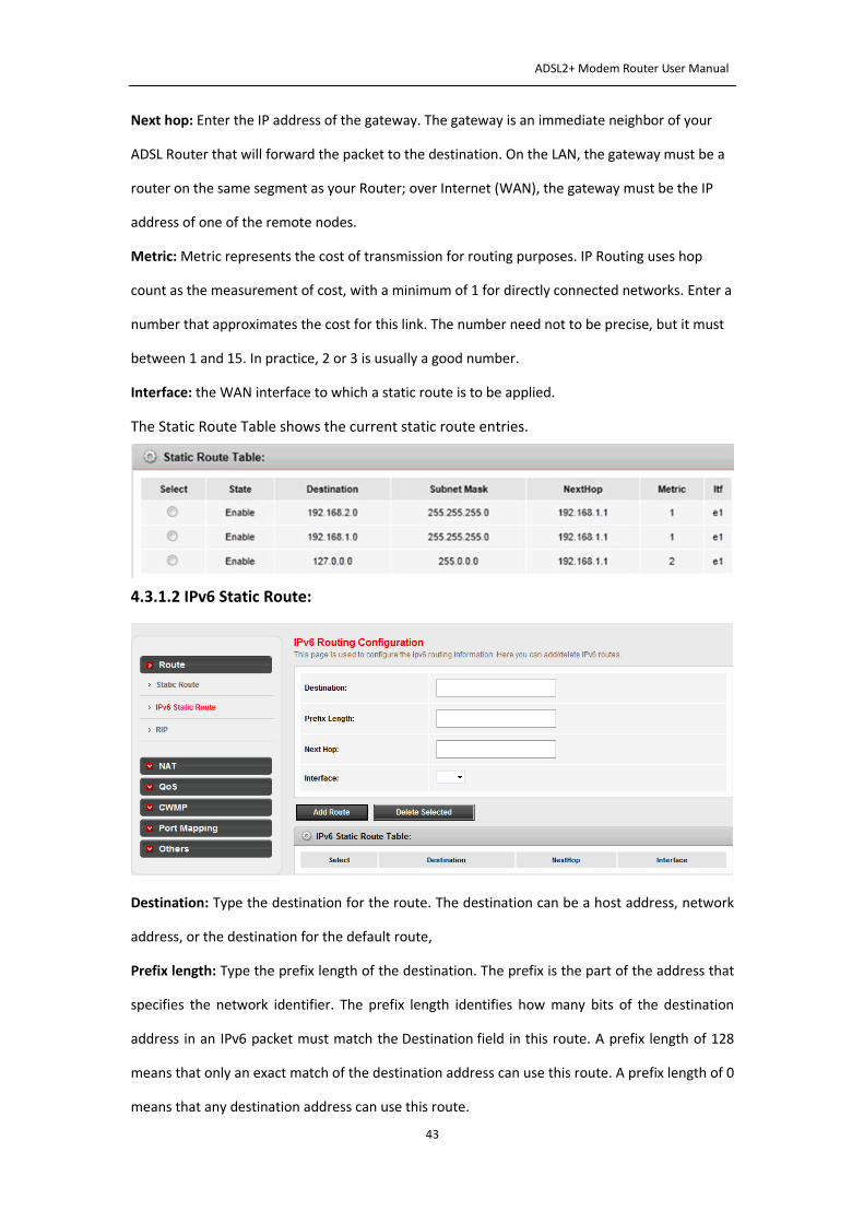
The Static Route Table shows the current static route entries.
4.3.1.2 IPv6 Static Route:
Destination: Type the destination for the route. The destination can be a host address, network
address, or the destination for the default route,
Prefix length: Type the prefix length of the destination. The prefix is the part of the address that
specifies the network identifier. The prefix length identifies how many bits of the destination
address in an IPv6 packet must match the Destination field in this route. A prefix length of 128
means that only an exact match of the destination address can use this route. A prefix length of 0
means that any destination address can use this route.
ADSL2+ Modem Router User Manual
44
Next hop: Type the IPv6 address for next hop for this route. For LAN interfaces, the gateway
address must be configured and must be a directly reachable IP address on the network segment
of the selected interface. For demand-dial interfaces, the gateway address is not configured or
used.
Interface: Lists the available LAN or demand-dial interfaces. Select the one to be used to forward
the IP packet if this route is selected.
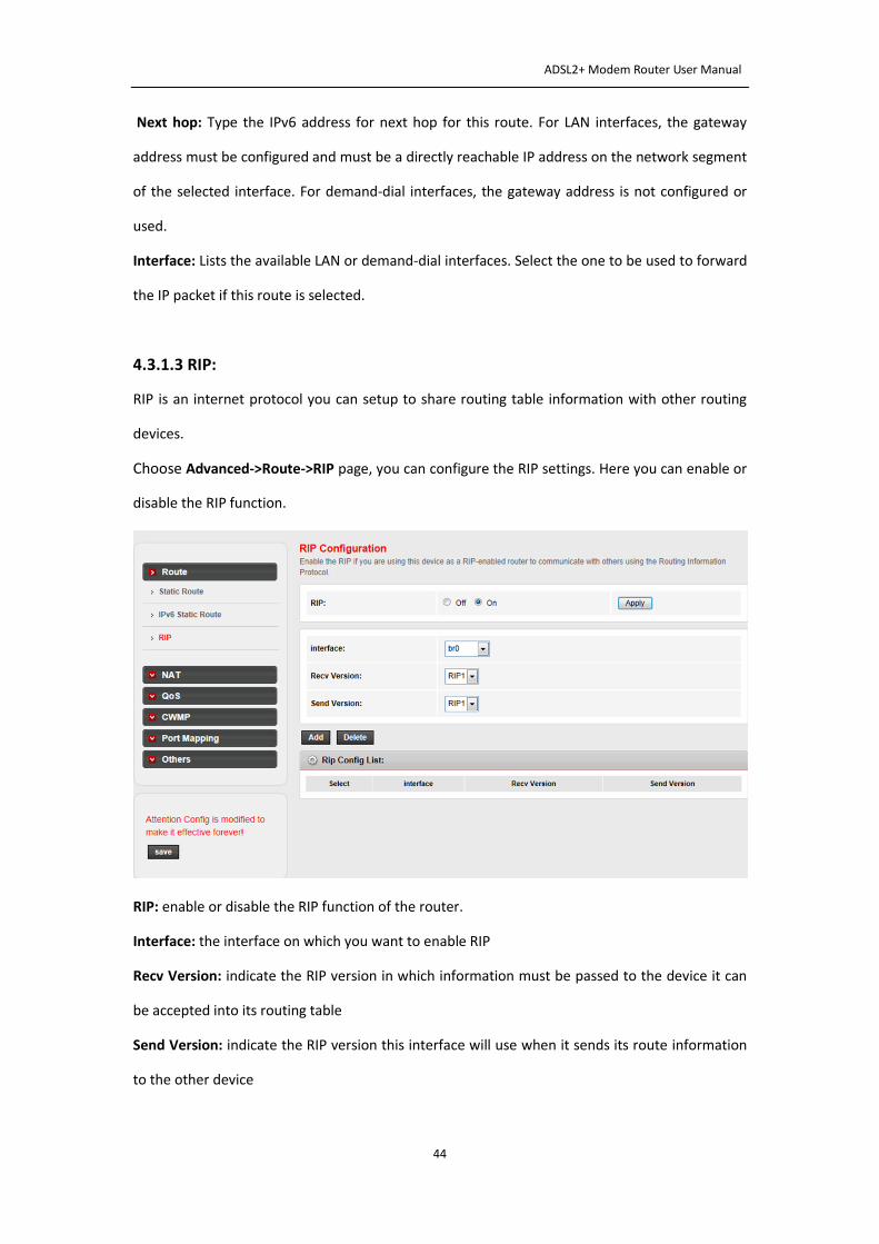
4.3.1.3 RIP:
RIP is an internet protocol you can setup to share routing table information with other routing
devices.
Choose Advanced->Route->RIP page, you can configure the RIP settings. Here you can enable or
disable the RIP function.
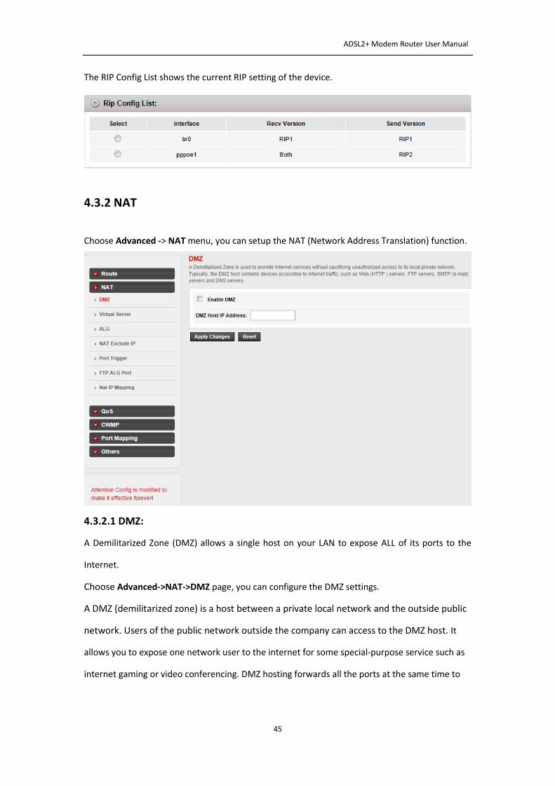
RIP: enable or disable the RIP function of the router.
Interface: the interface on which you want to enable RIP
Recv Version: indicate the RIP version in which information must be passed to the device it can
be accepted into its routing table
Send Version: indicate the RIP version this interface will use when it sends its route information
to the other device
ADSL2+ Modem Router User Manual
45
The RIP Config List shows the current RIP setting of the device.
4.3.2 NAT
Choose Advanced -> NAT menu, you can setup the NAT (Network Address Translation) function.
4.3.2.1 DMZ:
A Demilitarized Zone (DMZ) allows a single host on your LAN to expose ALL of its ports to the
Internet.
Choose Advanced->NAT->DMZ page, you can configure the DMZ settings.
A DMZ (demilitarized zone) is a host between a private local network and the outside public
network. Users of the public network outside the company can access to the DMZ host. It
allows you to expose one network user to the internet for some special-purpose service such as
internet gaming or video conferencing. DMZ hosting forwards all the ports at the same time to
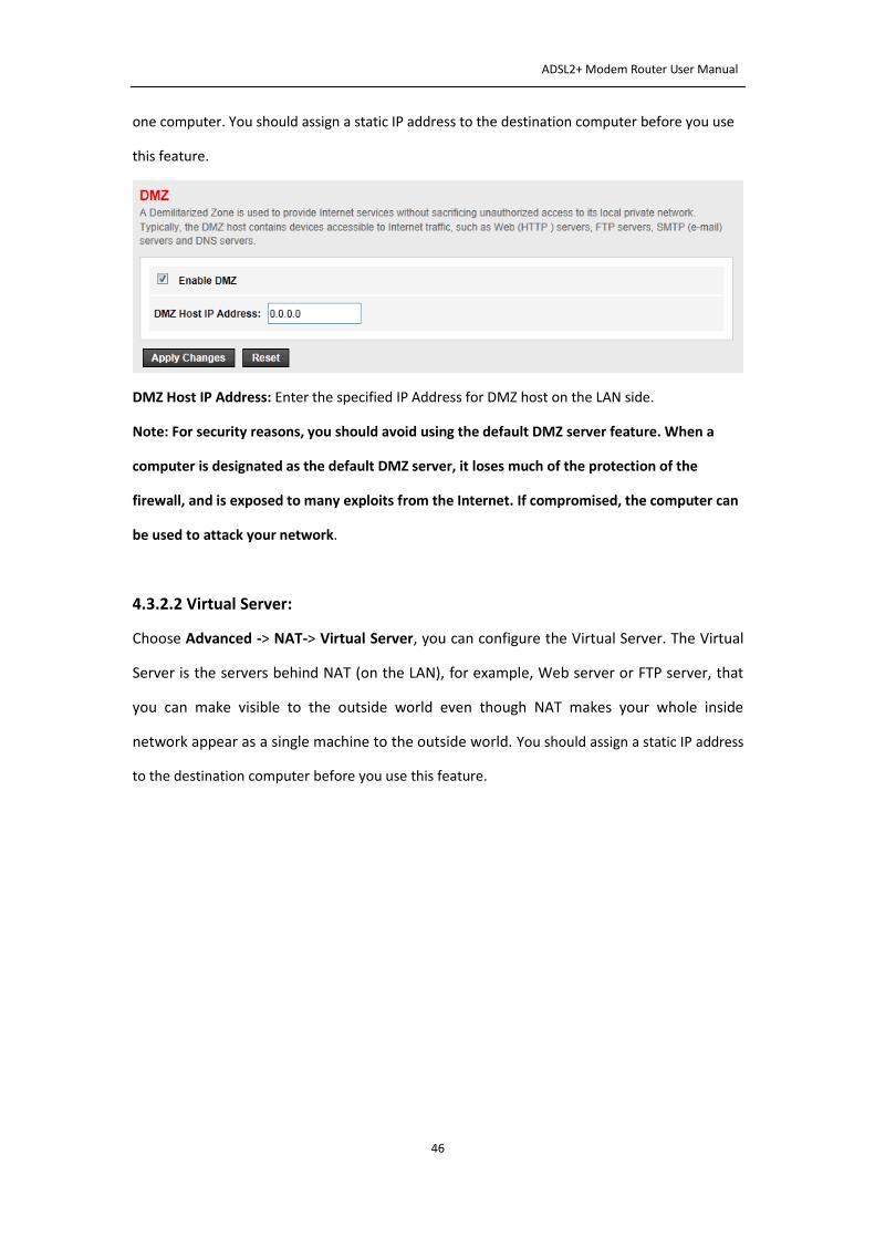
ADSL2+ Modem Router User Manual
46
one computer. You should assign a static IP address to the destination computer before you use
this feature.
DMZ Host IP Address: Enter the specified IP Address for DMZ host on the LAN side.
Note: For security reasons, you should avoid using the default DMZ server feature. When a
computer is designated as the default DMZ server, it loses much of the protection of the
firewall, and is exposed to many exploits from the Internet. If compromised, the computer can
be used to attack your network.
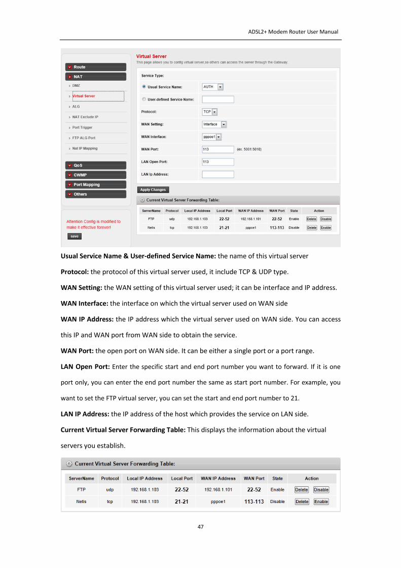
4.3.2.2 Virtual Server:
Choose Advanced -> NAT-> Virtual Server, you can configure the Virtual Server. The Virtual
Server is the servers behind NAT (on the LAN), for example, Web server or FTP server, that
you can make visible to the outside world even though NAT makes your whole inside
network appear as a single machine to the outside world. You should assign a static IP address
to the destination computer before you use this feature.
ADSL2+ Modem Router User Manual
47
Usual Service Name & User-defined Service Name: the name of this virtual server
Protocol: the protocol of this virtual server used, it include TCP & UDP type.
WAN Setting: the WAN setting of this virtual server used; it can be interface and IP address.
WAN Interface: the interface on which the virtual server used on WAN side
WAN IP Address: the IP address which the virtual server used on WAN side. You can access
this IP and WAN port from WAN side to obtain the service.
WAN Port: the open port on WAN side. It can be either a single port or a port range.
LAN Open Port: Enter the specific start and end port number you want to forward. If it is one
port only, you can enter the end port number the same as start port number. For example, you
want to set the FTP virtual server, you can set the start and end port number to 21.
LAN IP Address: the IP address of the host which provides the service on LAN side.
Current Virtual Server Forwarding Table: This displays the information about the virtual
servers you establish.
ADSL2+ Modem Router User Manual
48
Click Delete/Disable、Enable to make your operation get corresponding effect.
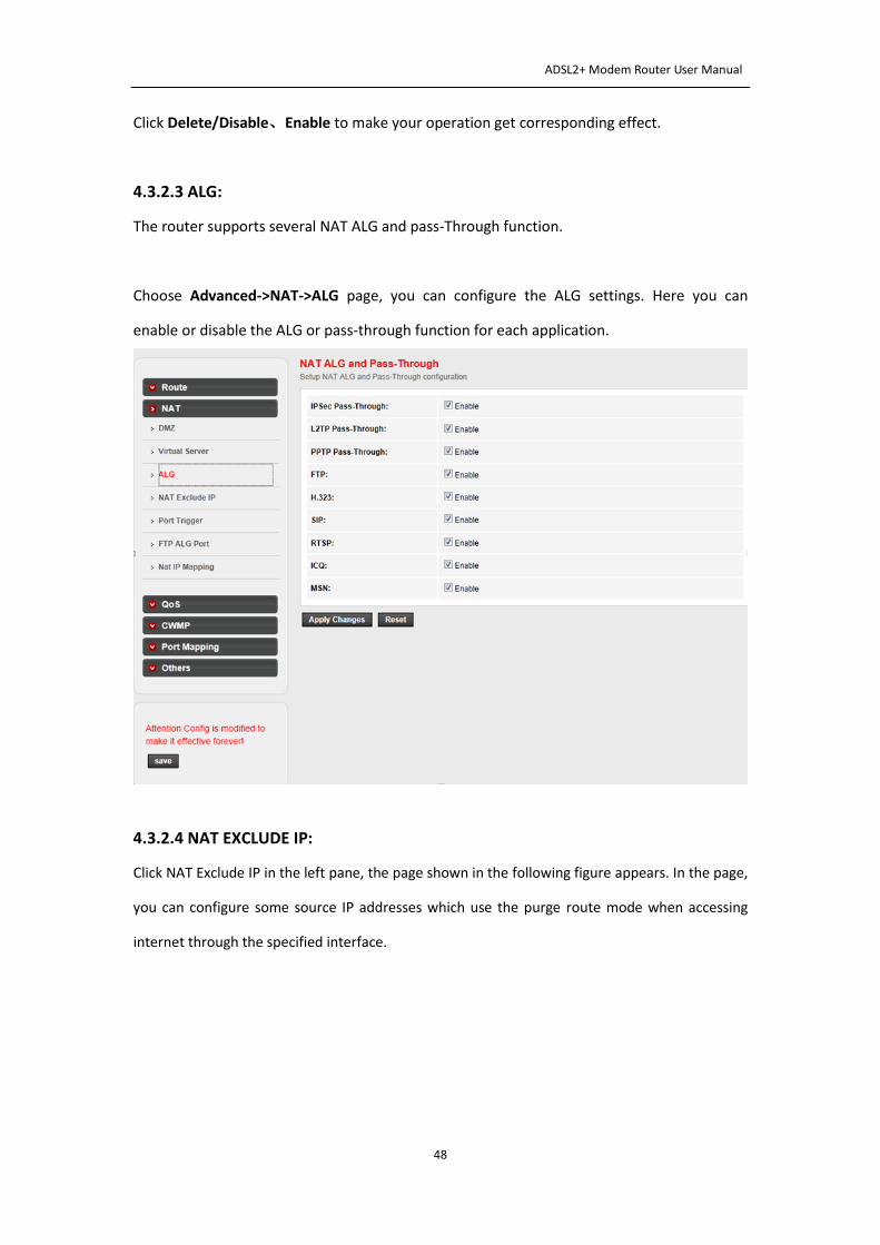
4.3.2.3 ALG:
The router supports several NAT ALG and pass-Through function.
Choose Advanced->NAT->ALG page, you can configure the ALG settings. Here you can
enable or disable the ALG or pass-through function for each application.
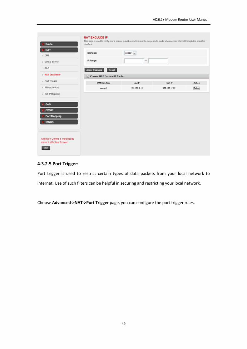
4.3.2.4 NAT EXCLUDE IP:
Click NAT Exclude IP in the left pane, the page shown in the following figure appears. In the page,
you can configure some source IP addresses which use the purge route mode when accessing
internet through the specified interface.
ADSL2+ Modem Router User Manual
49
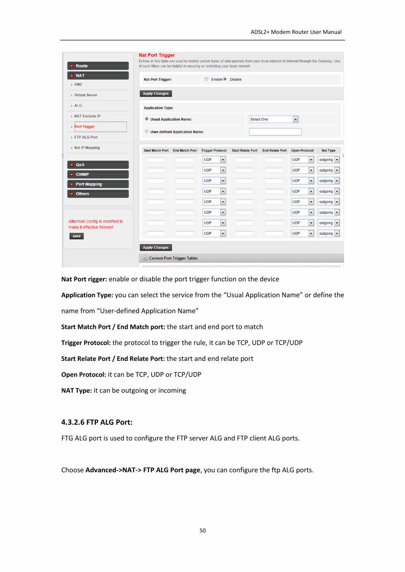
4.3.2.5 Port Trigger:
Port trigger is used to restrict certain types of data packets from your local network to
internet. Use of such filters can be helpful in securing and restricting your local network.
Choose Advanced->NAT->Port Trigger page, you can configure the port trigger rules.
ADSL2+ Modem Router User Manual
50
Nat Port rigger: enable or disable the port trigger function on the device
Application Type: you can select the service from the “Usual Application Name” or define the
name from “User-defined Application Name”
Start Match Port / End Match port: the start and end port to match
Trigger Protocol: the protocol to trigger the rule, it can be TCP, UDP or TCP/UDP
Start Relate Port / End Relate Port: the start and end relate port
Open Protocol: it can be TCP, UDP or TCP/UDP
NAT Type: it can be outgoing or incoming
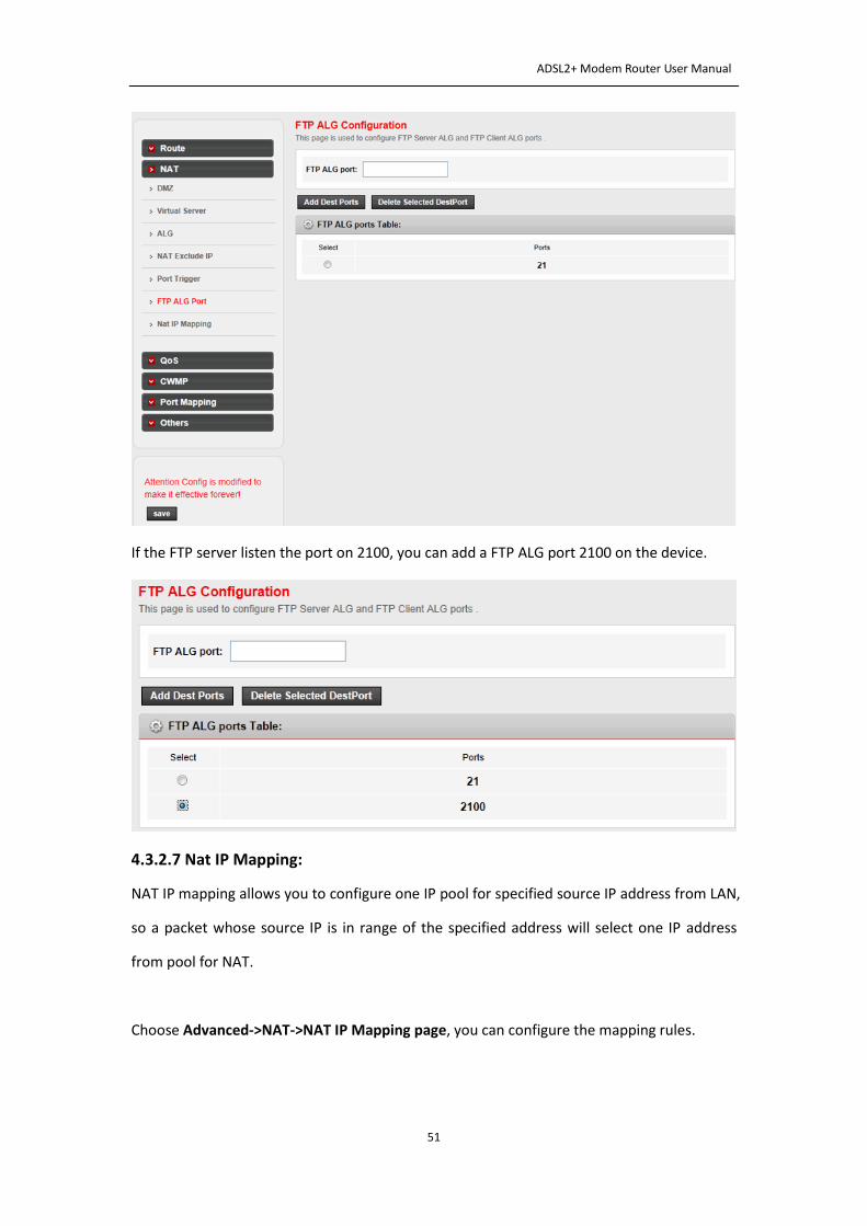
4.3.2.6 FTP ALG Port:
FTG ALG port is used to configure the FTP server ALG and FTP client ALG ports.
Choose Advanced->NAT-> FTP ALG Port page, you can configure the ftp ALG ports.
ADSL2+ Modem Router User Manual
51
If the FTP server listen the port on 2100, you can add a FTP ALG port 2100 on the device.
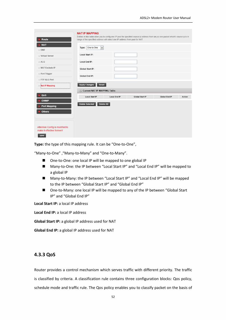
4.3.2.7 Nat IP Mapping:
NAT IP mapping allows you to configure one IP pool for specified source IP address from LAN,
so a packet whose source IP is in range of the specified address will select one IP address
from pool for NAT.
Choose Advanced->NAT->NAT IP Mapping page, you can configure the mapping rules.
ADSL2+ Modem Router User Manual
52
Type: the type of this mapping rule. It can be “One-to-One”,
“Many-to-One” ,“Many-to-Many” and “One-to-Many”.
One-to-One: one local IP will be mapped to one global IP
Many-to-One: the IP between “Local Start IP” and “Local End IP” will be mapped to
a global IP
Many-to-Many: the IP between “Local Start IP” and “Local End IP” will be mapped
to the IP between “Global Start IP” and “Global End IP”
One-to-Many: one local IP will be mapped to any of the IP between “Global Start
IP” and “Global End IP”
Local Start IP: a local IP address
Local End IP: a local IP address
Global Start IP: a global IP address used for NAT
Global End IP: a global IP address used for NAT
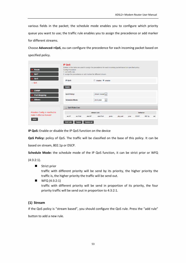
4.3.3 QoS
Router provides a control mechanism which serves traffic with different priority. The traffic
is classified by criteria. A classification rule contains three configuration blocks: Qos policy,
schedule mode and traffic rule. The Qos policy enables you to classify packet on the basis of
ADSL2+ Modem Router User Manual
53
various fields in the packet; the schedule mode enables you to configure which priority
queue you want to use; the traffic rule enables you to assign the precedence or add marker
for different streams.
Choose Advanced->QoS, ou can configure the precedence for each incoming packet based on
specified policy.
IP QoS: Enable or disable the IP QoS function on the device
QoS Policy: policy of QoS. The traffic will be classified on the base of this policy. It can be
based on stream, 802.1p or DSCP.
Schedule Mode: the schedule mode of the IP QoS function, it can be strict prior or WFQ
(4:3:2:1).
Strict prior
traffic with different priority will be send by its priority, the higher priority the
traffic is, the higher priority the traffic will be send out.
WFQ (4:3:2:1)
traffic with different priority will be send in proportion of its priority, the four
priority traffic will be send out in proportion to 4:3:2:1.
(1) Stream
If the QoS policy is “stream based”, you should configure the QoS rule. Press the “add rule”
button to add a new rule.
ADSL2+ Modem Router User Manual
54
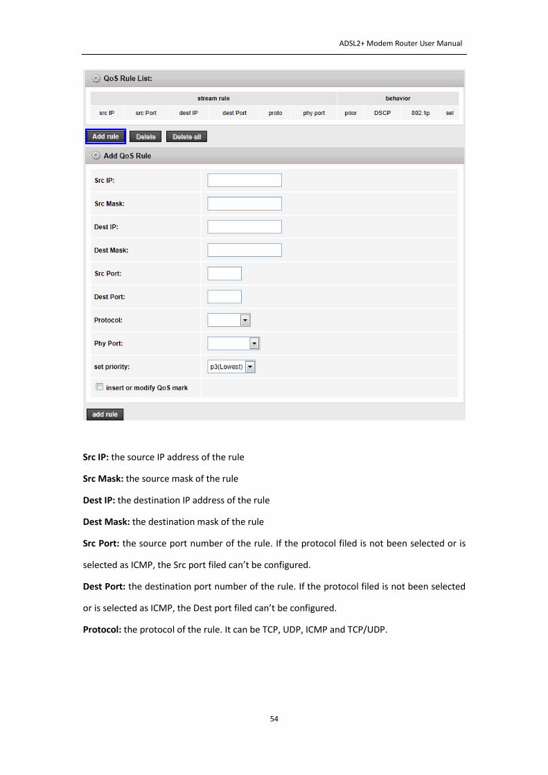
Src IP: the source IP address of the rule
Src Mask: the source mask of the rule
Dest IP: the destination IP address of the rule
Dest Mask: the destination mask of the rule
Src Port: the source port number of the rule. If the protocol filed is not been selected or is
selected as ICMP, the Src port filed can’t be configured.
Dest Port: the destination port number of the rule. If the protocol filed is not been selected
or is selected as ICMP, the Dest port filed can’t be configured.
Protocol: the protocol of the rule. It can be TCP, UDP, ICMP and TCP/UDP.
ADSL2+ Modem Router User Manual
55
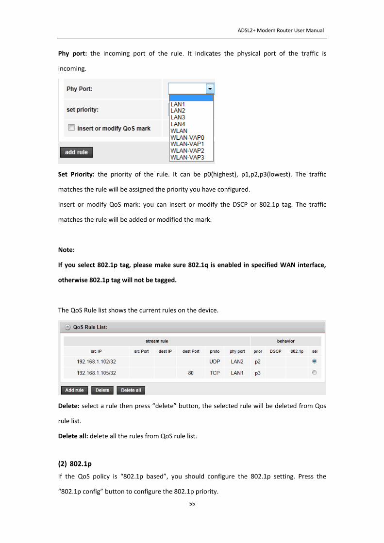
Phy port: the incoming port of the rule. It indicates the physical port of the traffic is
incoming.
Set Priority: the priority of the rule. It can be p0(highest), p1,p2,p3(lowest). The traffic
matches the rule will be assigned the priority you have configured.
Insert or modify QoS mark: you can insert or modify the DSCP or 802.1p tag. The traffic
matches the rule will be added or modified the mark.
Note:
If you select 802.1p tag, please make sure 802.1q is enabled in specified WAN interface,
otherwise 802.1p tag will not be tagged.
The QoS Rule list shows the current rules on the device.
Delete: select a rule then press “delete” button, the selected rule will be deleted from Qos
rule list.
Delete all: delete all the rules from QoS rule list.
(2) 802.1p
If the QoS policy is “802.1p based”, you should configure the 802.1p setting. Press the
“802.1p config” button to configure the 802.1p priority.
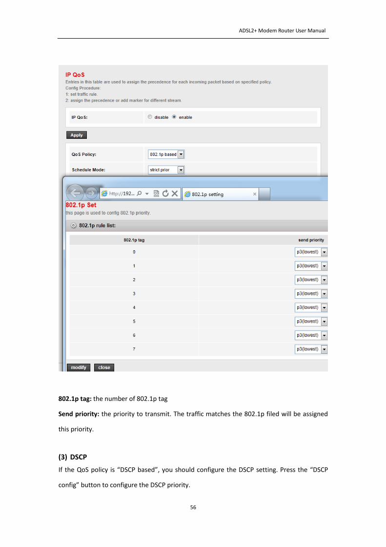
ADSL2+ Modem Router User Manual
56
802.1p tag: the number of 802.1p tag
Send priority: the priority to transmit. The traffic matches the 802.1p filed will be assigned
this priority.
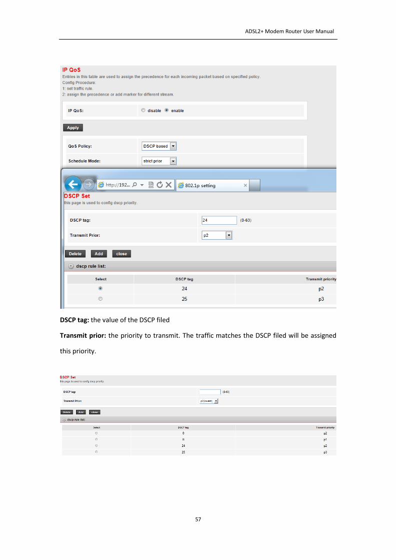
(3) DSCP
If the QoS policy is “DSCP based”, you should configure the DSCP setting. Press the “DSCP
config” button to configure the DSCP priority.
ADSL2+ Modem Router User Manual
57
DSCP tag: the value of the DSCP filed
Transmit prior: the priority to transmit. The traffic matches the DSCP filed will be assigned
this priority.

ADSL2+ Modem Router User Manual
58
4.3.4 CWMP
CPE WAN Management Protocol (CWMP) is a protocol for communication between a CPE
and Auto-Configuration Server (ACS). The router offers CWMP feature. The function
supports TR-069 protocol which collects information, diagnoses the devices and configures
the devices automatically via ACS (Auto-Configuration Server).
Choose Advanced->CWMP, you can configure the TR-069 CPE. Here you may change the
setting for the ACS’s parameters.
ACS parameters:
Enable: enable or disable the CWMP
URL: ACS URL.
User Name: the username the device should use when connecting to the ACS
Password: the password the device should use when connecting to the ACS
Periodic Inform Enable: when this field is enabled, the device will send an Inform RPC to the
ACS server at the system startup, and will continue to send it periodically at an interval
ADSL2+ Modem Router User Manual
59
defined in “Periodic Inform Interval” field; when this field is disabled, the device will only
send Inform RPC to the ACS server once at the system startup.
Periodic Inform Interval: the interval to send Inform RPC
Connection Request parameters:
User Name: username the remote ACS should use when connecting to the device
Password: password the remote ACS should use when connecting to the device
Path: the path of the device Connection Request URL.
Port: the port of the device Connection Request URL
4.3.5 Port Mapping
The device provides multiple interface groups, up to five interface groups are supported
including one default group. Traffic coming from one interface of a group can only be flowed
to the interfaces in the same interface group. Thus, the device can isolate traffic from group
to group for soma application. By default, all the interfaces (LAN and WAN) belong to the
default group, and the other four groups are all empty. It is possible to assign any interface
to any group but only one group.
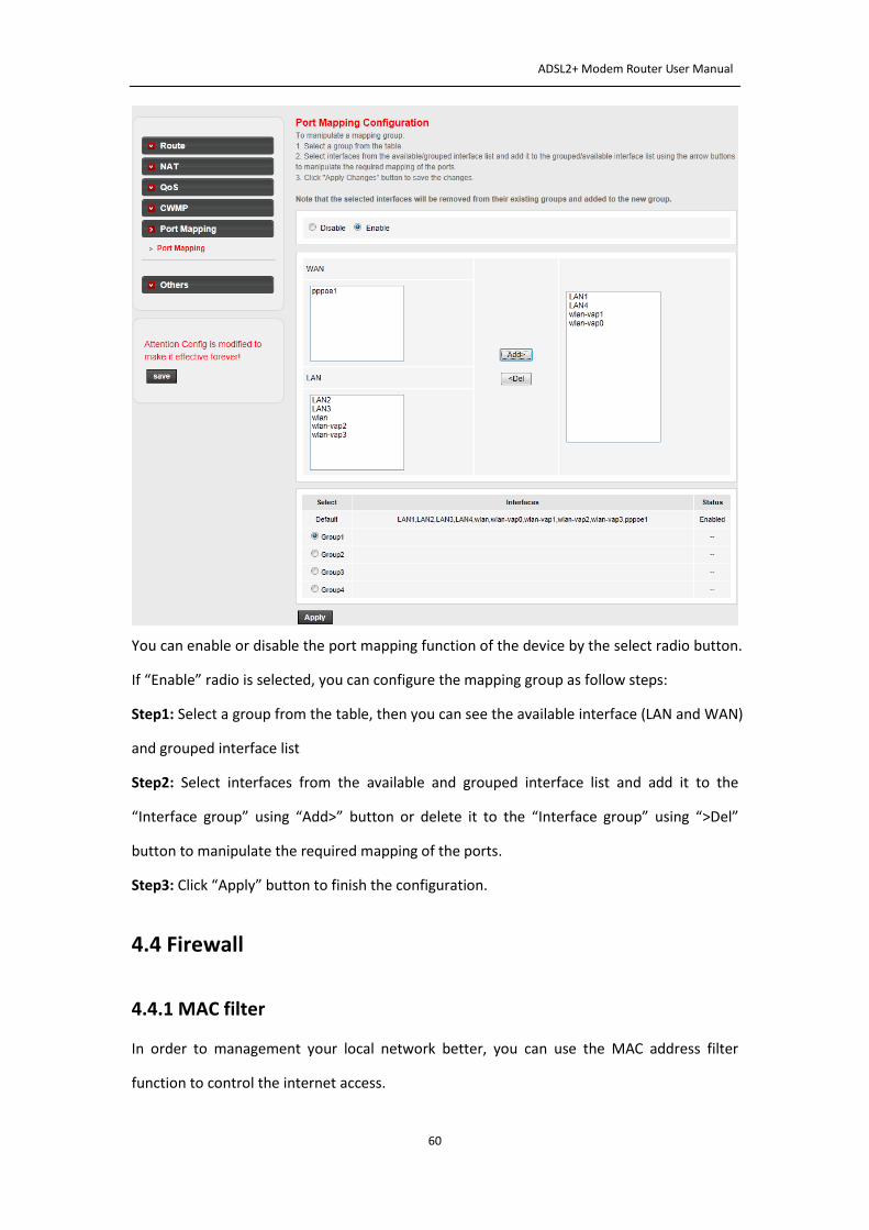
Choose Advanced->Port Mapping page, you can configure the mapping group.
ADSL2+ Modem Router User Manual
60
You can enable or disable the port mapping function of the device by the select radio button.
If “Enable” radio is selected, you can configure the mapping group as follow steps:
Step1: Select a group from the table, then you can see the available interface (LAN and WAN)
and grouped interface list
Step2: Select interfaces from the available and grouped interface list and add it to the
“Interface group” using “Add>” button or delete it to the “Interface group” using “>Del”
button to manipulate the required mapping of the ports.
Step3: Click “Apply” button to finish the configuration.
4.4 Firewall
4.4.1 MAC filter
In order to management your local network better, you can use the MAC address filter
function to control the internet access.
ADSL2+ Modem Router User Manual
61
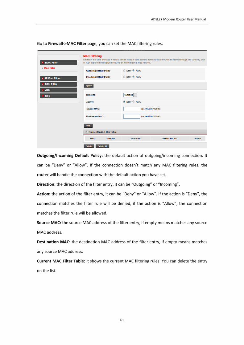
Go to Firewall->MAC Filter page, you can set the MAC filtering rules.
Outgoing/Incoming Default Policy: the default action of outgoing/incoming connection. It
can be “Deny” or “Allow”. If the connection doesn’t match any MAC filtering rules, the
router will handle the connection with the default action you have set.
Direction: the direction of the filter entry, it can be “Outgoing” or “Incoming”.
Action: the action of the filter entry, it can be “Deny” or “Allow”. If the action is “Deny”, the
connection matches the filter rule will be denied, if the action is “Allow”, the connection
matches the filter rule will be allowed.
Source MAC: the source MAC address of the filter entry, if empty means matches any source
MAC address.
Destination MAC: the destination MAC address of the filter entry, if empty means matches
any source MAC address.
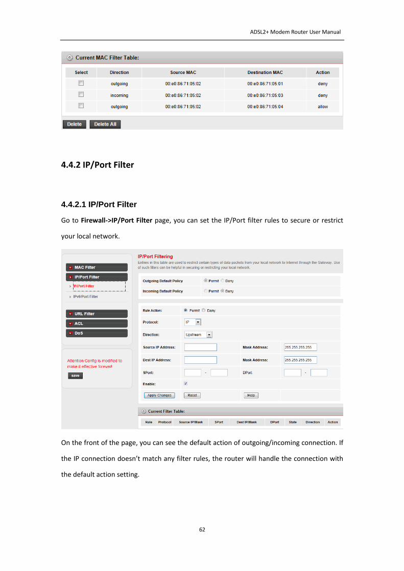
Current MAC Filter Table: it shows the current MAC filtering rules. You can delete the entry
on the list.
ADSL2+ Modem Router User Manual
62
4.4.2 IP/Port Filter
4.4.2.1 IP/Port Filter
Go to Firewall->IP/Port Filter page, you can set the IP/Port filter rules to secure or restrict
your local network.
On the front of the page, you can see the default action of outgoing/incoming connection. If
the IP connection doesn’t match any filter rules, the router will handle the connection with
the default action setting.
ADSL2+ Modem Router User Manual
63
Rule Action: the filter mode of this entry, it can be “Permit” and “Deny”. If the mode is
“Permit”, the IP connection matches the rule will be permitted, if the mode is “Deny”, the IP
connection matches the rule will be denied.
Protocol: the protocol of this entry, it can be “IP”, “ICMP”, “TCP” and “UDP”.
Direction: the direction of this entry, it can be “upstream” and “Downstream”.
Source IP Address/ Mask Address: the source IP address and mask address of the entry.
Dest IP Address/ Mask Address: the destination IP address and mask address of the entry.
Sport: If the protocol is “TCP” or “UDP”, you should set the source port of the entry, it can
be a single port or a port range.
Dport: If the protocol is “TCP” or “UDP”, you should set the destination port of the entry, it
can be a single port or a port range.
Enable: enable or disable this filter entry.
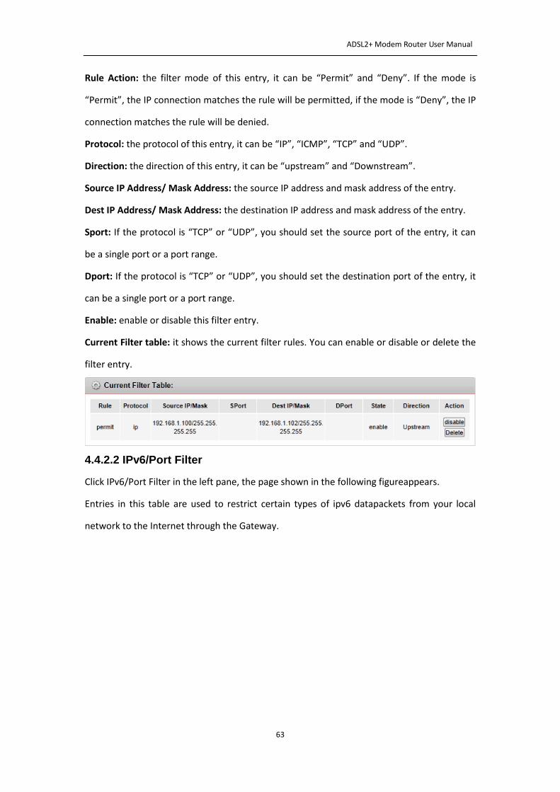
Current Filter table: it shows the current filter rules. You can enable or disable or delete the
filter entry.
4.4.2.2 IPv6/Port Filter
Click IPv6/Port Filter in the left pane, the page shown in the following figureappears.
Entries in this table are used to restrict certain types of ipv6 datapackets from your local
network to the Internet through the Gateway.
ADSL2+ Modem Router User Manual
64
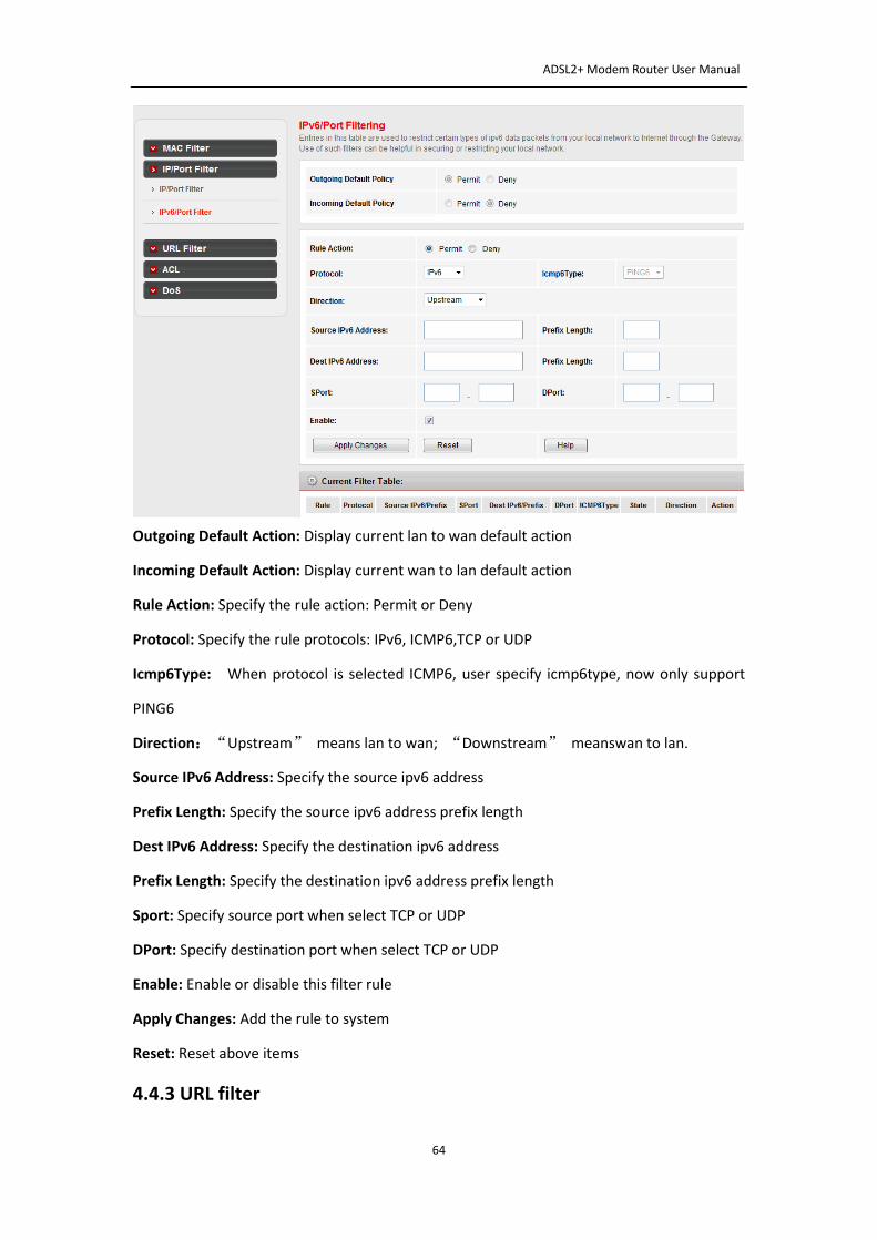
Outgoing Default Action: Display current lan to wan default action
Incoming Default Action: Display current wan to lan default action
Rule Action: Specify the rule action: Permit or Deny
Protocol: Specify the rule protocols: IPv6, ICMP6,TCP or UDP
Icmp6Type: When protocol is selected ICMP6, user specify icmp6type, now only support
PING6
Direction:“Upstream” means lan to wan; “Downstream” meanswan to lan.
Source IPv6 Address: Specify the source ipv6 address
Prefix Length: Specify the source ipv6 address prefix length
Dest IPv6 Address: Specify the destination ipv6 address
Prefix Length: Specify the destination ipv6 address prefix length
Sport: Specify source port when select TCP or UDP
DPort: Specify destination port when select TCP or UDP
Enable: Enable or disable this filter rule
Apply Changes: Add the rule to system
Reset: Reset above items
4.4.3 URL filter
ADSL2+ Modem Router User Manual
65
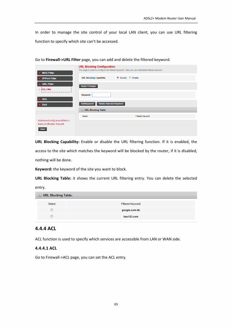
In order to manage the site control of your local LAN client, you can use URL filtering
function to specify which site can’t be accessed.
Go to Firewall->URL Filter page, you can add and delete the filtered keyword.
URL Blocking Capability: Enable or disable the URL filtering function. If it is enabled, the
access to the site which matches the keyword will be blocked by the router, if it is disabled,
nothing will be done.
Keyword: the keyword of the site you want to block.
URL Blocking Table: it shows the current URL filtering entry. You can delete the selected
entry.
4.4.4 ACL
ACL function is used to specify which services are accessible from LAN or WAN side.
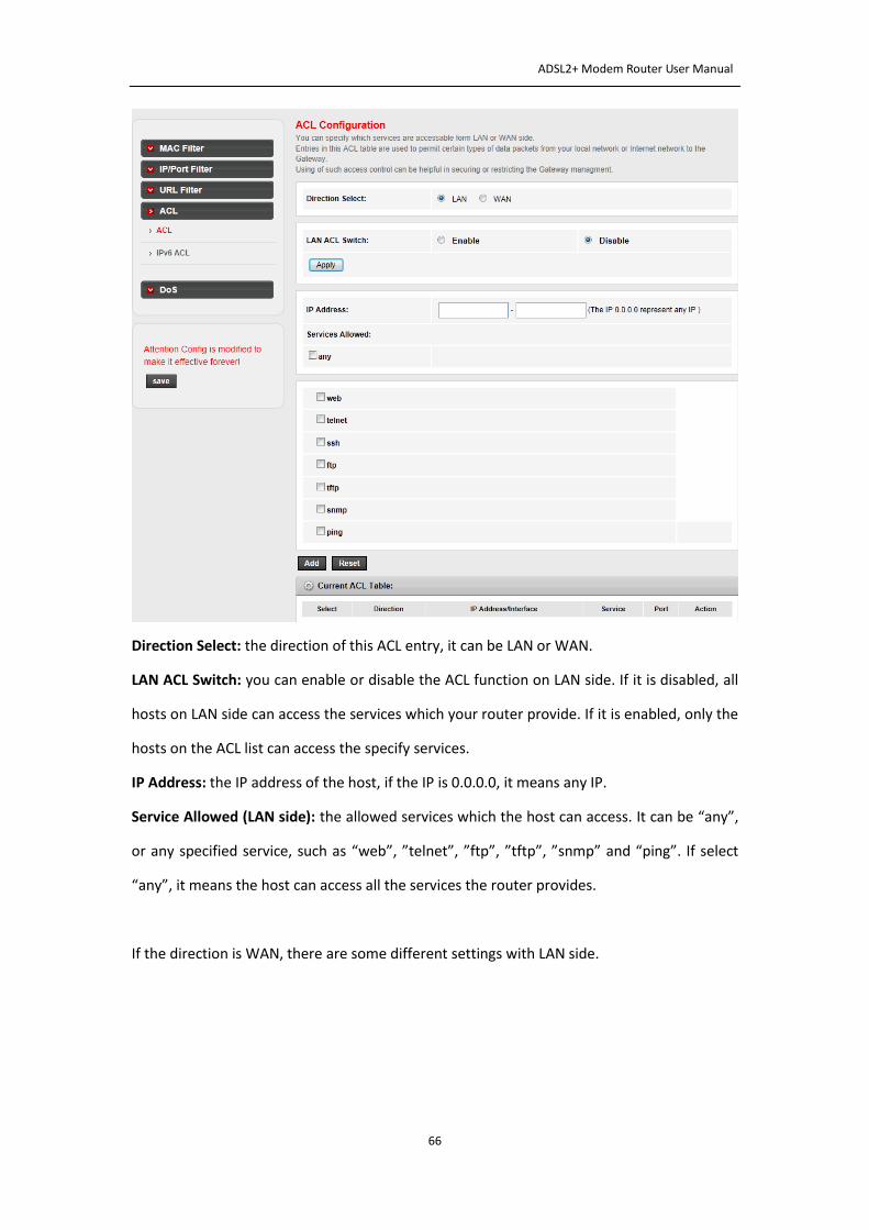
4.4.4.1 ACL
Go to Firewall->ACL page, you can set the ACL entry.
ADSL2+ Modem Router User Manual
66
Direction Select: the direction of this ACL entry, it can be LAN or WAN.
LAN ACL Switch: you can enable or disable the ACL function on LAN side. If it is disabled, all
hosts on LAN side can access the services which your router provide. If it is enabled, only the
hosts on the ACL list can access the specify services.
IP Address: the IP address of the host, if the IP is 0.0.0.0, it means any IP.
Service Allowed (LAN side): the allowed services which the host can access. It can be “any”,
or any specified service, such as “web”, ”telnet”, ”ftp”, ”tftp”, ”snmp” and “ping”. If select
“any”, it means the host can access all the services the router provides.
If the direction is WAN, there are some different settings with LAN side.
ADSL2+ Modem Router User Manual
67
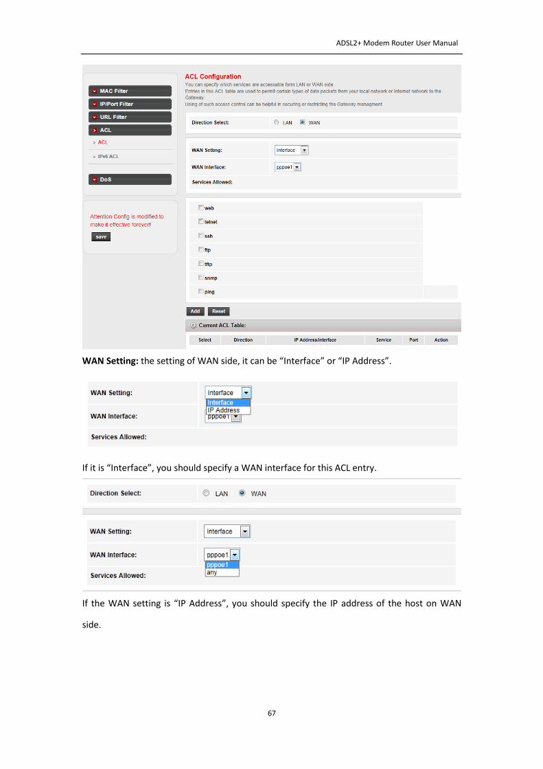
WAN Setting: the setting of WAN side, it can be “Interface” or “IP Address”.
If it is “Interface”, you should specify a WAN interface for this ACL entry.
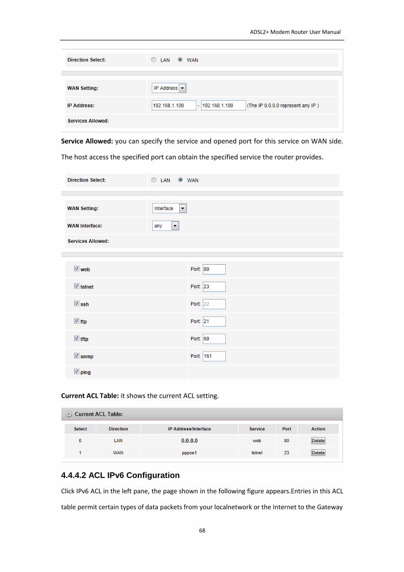
If the WAN setting is “IP Address”, you should specify the IP address of the host on WAN
side.
ADSL2+ Modem Router User Manual
68
Service Allowed: you can specify the service and opened port for this service on WAN side.
The host access the specified port can obtain the specified service the router provides.
Current ACL Table: it shows the current ACL setting.
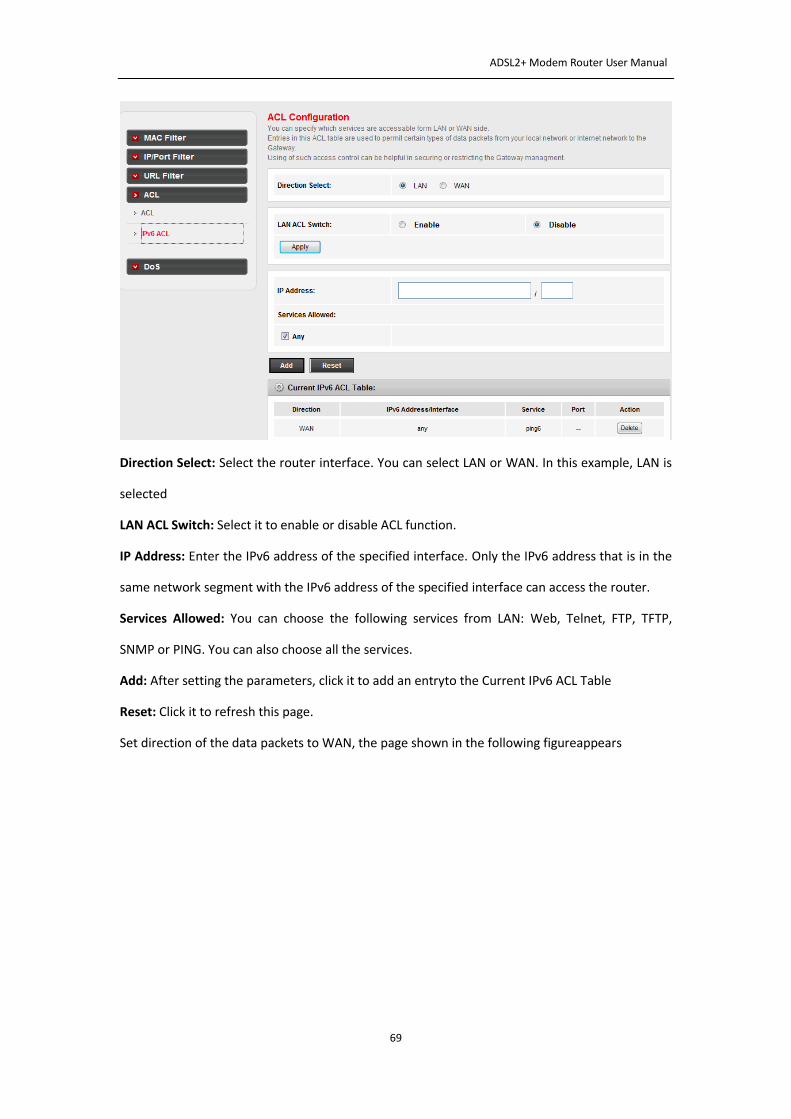
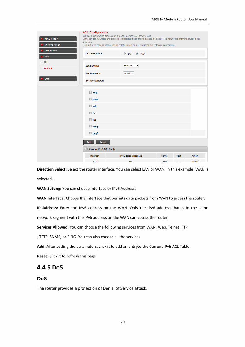
4.4.4.2 ACL IPv6 Configuration
Click IPv6 ACL in the left pane, the page shown in the following figure appears.Entries in this ACL
table permit certain types of data packets from your localnetwork or the Internet to the Gateway
ADSL2+ Modem Router User Manual
69
Direction Select: Select the router interface. You can select LAN or WAN. In this example, LAN is
selected
LAN ACL Switch: Select it to enable or disable ACL function.
IP Address: Enter the IPv6 address of the specified interface. Only the IPv6 address that is in the
same network segment with the IPv6 address of the specified interface can access the router.
Services Allowed: You can choose the following services from LAN: Web, Telnet, FTP, TFTP,
SNMP or PING. You can also choose all the services.
Add: After setting the parameters, click it to add an entryto the Current IPv6 ACL Table
Reset: Click it to refresh this page.
Set direction of the data packets to WAN, the page shown in the following figureappears
ADSL2+ Modem Router User Manual
70
Direction Select: Select the router interface. You can select LAN or WAN. In this example, WAN is
selected.
WAN Setting: You can choose Interface or IPv6 Address.
WAN Interface: Choose the interface that permits data packets from WAN to access the router.
IP Address: Enter the IPv6 address on the WAN. Only the IPv6 address that is in the same
network segment with the IPv6 address on the WAN can access the router.
Services Allowed: You can choose the following services from WAN: Web, Telnet, FTP
, TFTP, SNMP, or PING. You can also choose all the services.
Add: After setting the parameters, click it to add an entryto the Current IPv6 ACL Table.
Reset: Click it to refresh this page
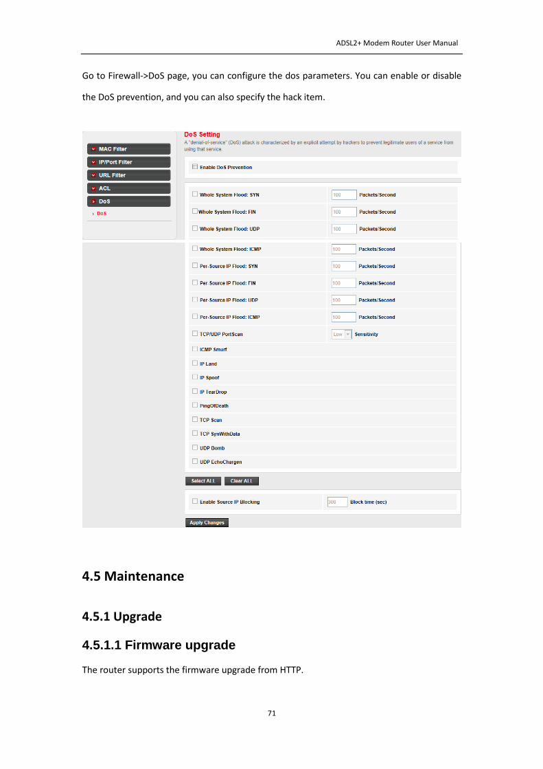
4.4.5 DoS
DoS
The router provides a protection of Denial of Service attack.
ADSL2+ Modem Router User Manual
71
Go to Firewall->DoS page, you can configure the dos parameters. You can enable or disable
the DoS prevention, and you can also specify the hack item.
4.5 Maintenance
4.5.1 Upgrade
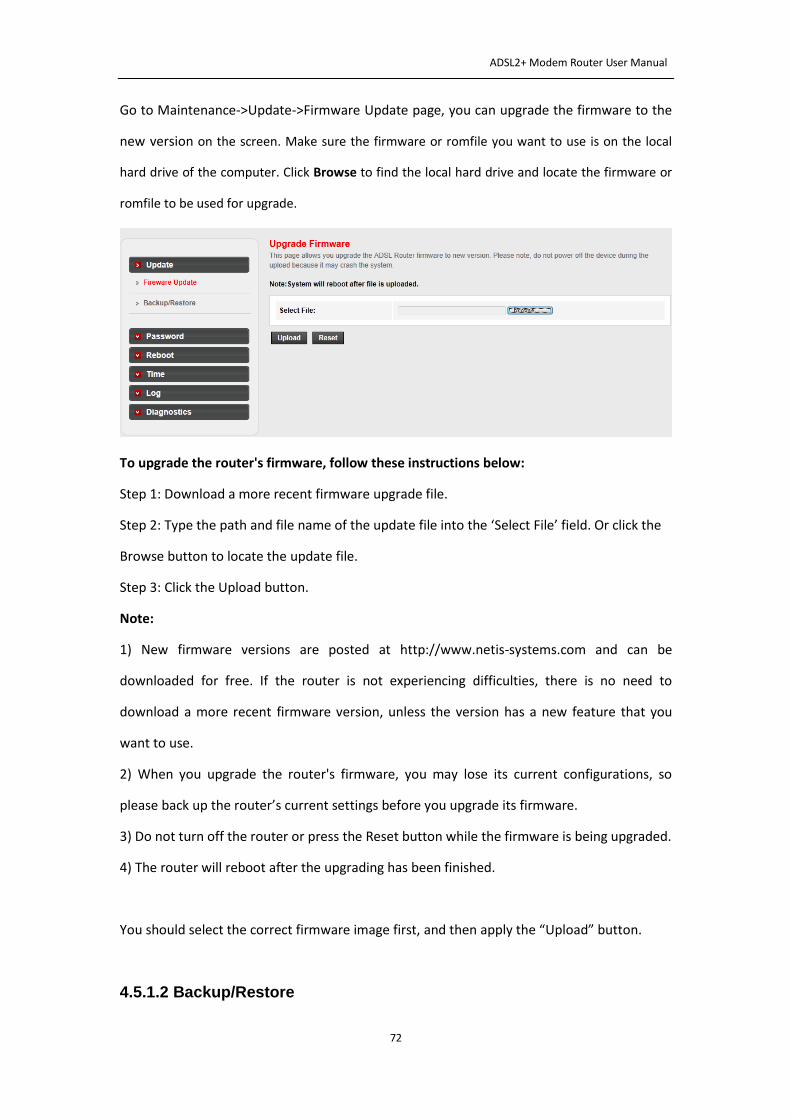
4.5.1.1 Firmware upgrade
The router supports the firmware upgrade from HTTP.
ADSL2+ Modem Router User Manual
72
Go to Maintenance->Update->Firmware Update page, you can upgrade the firmware to the
new version on the screen. Make sure the firmware or romfile you want to use is on the local
hard drive of the computer. Click Browse to find the local hard drive and locate the firmware or
romfile to be used for upgrade.
To upgrade the router's firmware, follow these instructions below:
Step 1: Download a more recent firmware upgrade file.
Step 2: Type the path and file name of the update file into the ‘Select File’ field. Or click the
Browse button to locate the update file.
Step 3: Click the Upload button.
Note:
1) New firmware versions are posted at http://www.netis-systems.com and can be
downloaded for free. If the router is not experiencing difficulties, there is no need to
download a more recent firmware version, unless the version has a new feature that you
want to use.
2) When you upgrade the router's firmware, you may lose its current configurations, so
please back up the router’s current settings before you upgrade its firmware.
3) Do not turn off the router or press the Reset button while the firmware is being upgraded.
4) The router will reboot after the upgrading has been finished.
You should select the correct firmware image first, and then apply the “Upload” button.
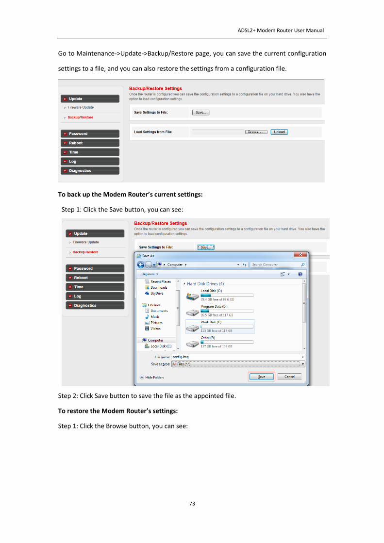
4.5.1.2 Backup/Restore
ADSL2+ Modem Router User Manual
73
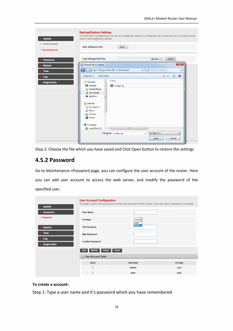
Go to Maintenance->Update->Backup/Restore page, you can save the current configuration
settings to a file, and you can also restore the settings from a configuration file.
To back up the Modem Router’s current settings:
Step 1: Click the Save button, you can see:
Step 2: Click Save button to save the file as the appointed file.
To restore the Modem Router’s settings:
Step 1: Click the Browse button, you can see:
ADSL2+ Modem Router User Manual
74
Step 2: Choose the file which you have saved and Click Open button to restore the settings
4.5.2 Password
Go to Maintenance->Password page, you can configure the user account of the router. Here
you can add user account to access the web server, and modify the password of the
specified user.
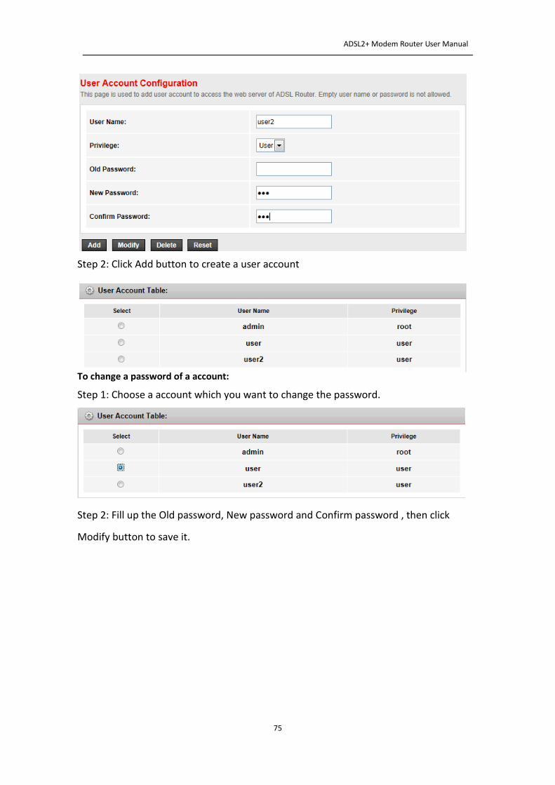
To create a account:
Step 1: Type a user name and it’s password which you have remembered
ADSL2+ Modem Router User Manual
75
Step 2: Click Add button to create a user account
To change a password of a account:
Step 1: Choose a account which you want to change the password.
Step 2: Fill up the Old password, New password and Confirm password , then click
Modify button to save it.
ADSL2+ Modem Router User Manual
76
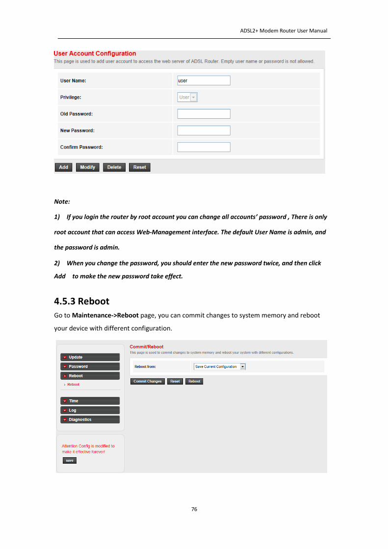
Note:
1) If you login the router by root account you can change all accounts’ password , There is only
root account that can access Web-Management interface. The default User Name is admin, and
the password is admin.
2) When you change the password, you should enter the new password twice, and then click
Add to make the new password take effect.
4.5.3 Reboot
Go to Maintenance->Reboot page, you can commit changes to system memory and reboot
your device with different configuration. Here you can also reset the current setting to the default settings.
ADSL2+ Modem Router User Manual
77
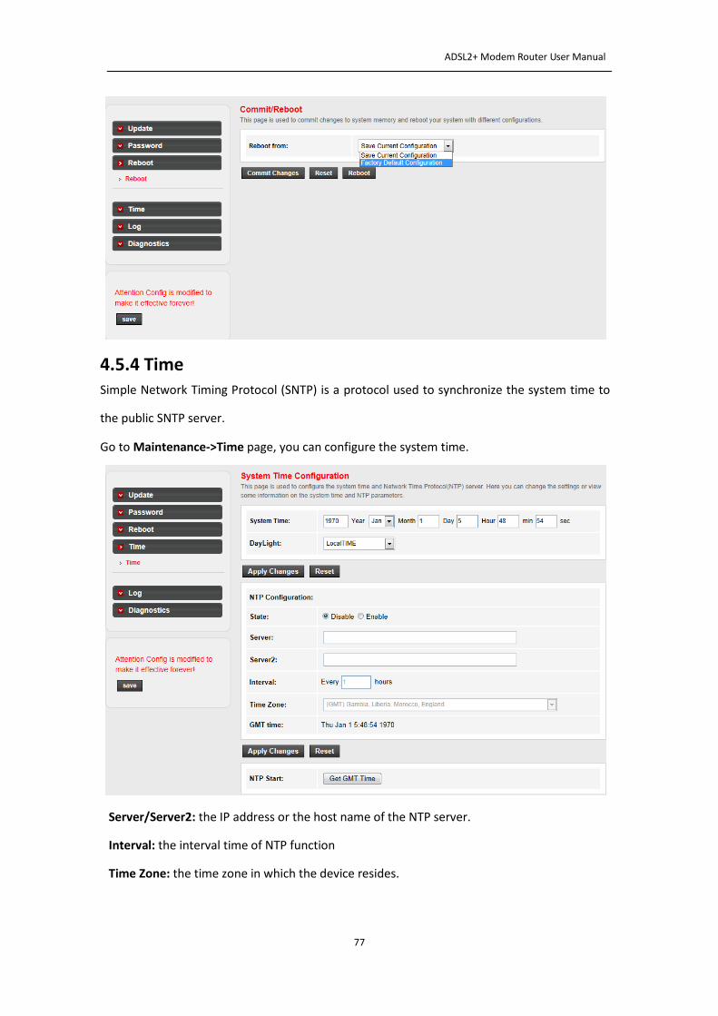
4.5.4 Time Simple Network Timing Protocol (SNTP) is a protocol used to synchronize the system time to
the public SNTP server.
Go to Maintenance->Time page, you can configure the system time.
NTP Configuration
State: the current state of NTP function.
Server/Server2: the IP address or the host name of the NTP server.
Interval: the interval time of NTP function
Time Zone: the time zone in which the device resides.
ADSL2+ Modem Router User Manual
78
When you set the NTP configuration correctly, press the button “Get GMT Time” to start the
NTP function. Then you can see the GMT time obtained from NTP server.
Note: The ADSL Router built-in some NTP Servers, when the Modem Router connects to
internet, it will get the system time automatically from the NTP Server. You can also configure
the NTP Server address manually, then it will get the time from the specific server firstly.
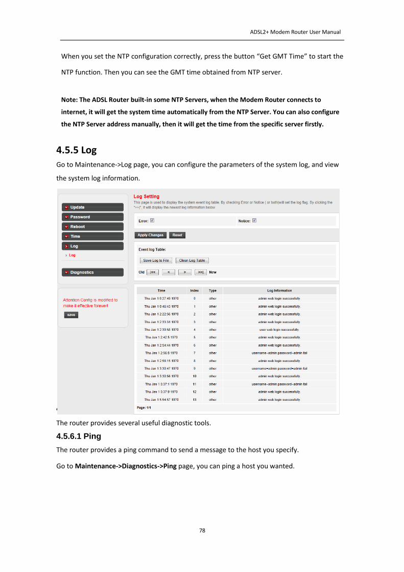
4.5.5 Log Go to Maintenance->Log page, you can configure the parameters of the system log, and view
the system log information.
4.5.6 Diagnostics
The router provides several useful diagnostic tools.
4.5.6.1 Ping
The router provides a ping command to send a message to the host you specify.
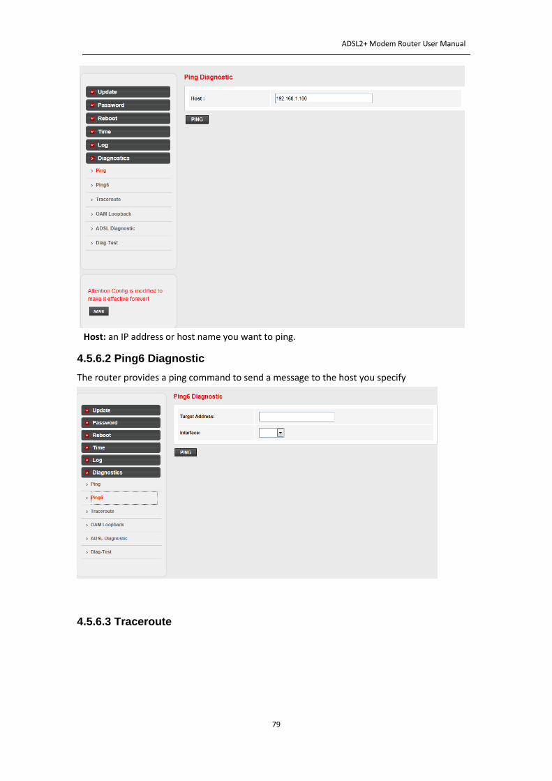
Go to Maintenance->Diagnostics->Ping page, you can ping a host you wanted.
ADSL2+ Modem Router User Manual
79
Host: an IP address or host name you want to ping.
4.5.6.2 Ping6 Diagnostic
The router provides a ping command to send a message to the host you specify
Target Address: an IPv6 address or host name you want to ping.
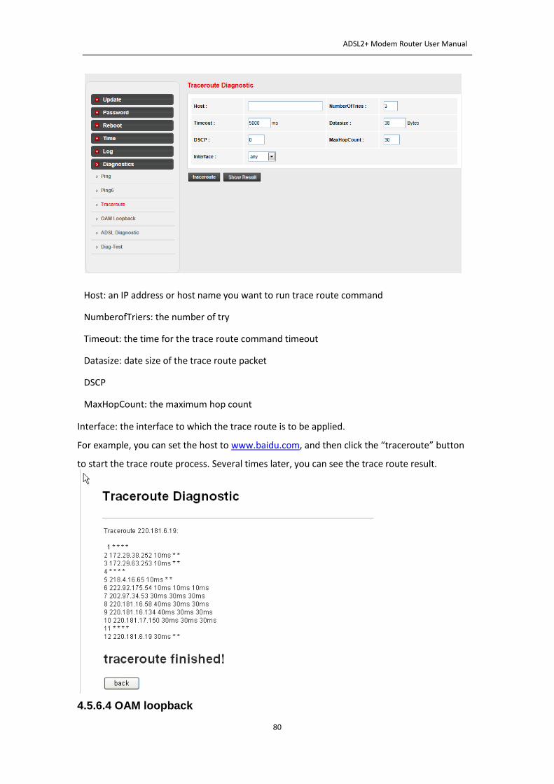
4.5.6.3 Traceroute
ADSL2+ Modem Router User Manual
80
Host: an IP address or host name you want to run trace route command
NumberofTriers: the number of try
Timeout: the time for the trace route command timeout
Datasize: date size of the trace route packet
DSCP
MaxHopCount: the maximum hop count
Interface: the interface to which the trace route is to be applied. For example, you can set the host to www.baidu.com, and then click the “traceroute” button
to start the trace route process. Several times later, you can see the trace route result.
4.5.6.4 OAM loopback
ADSL2+ Modem Router User Manual
81
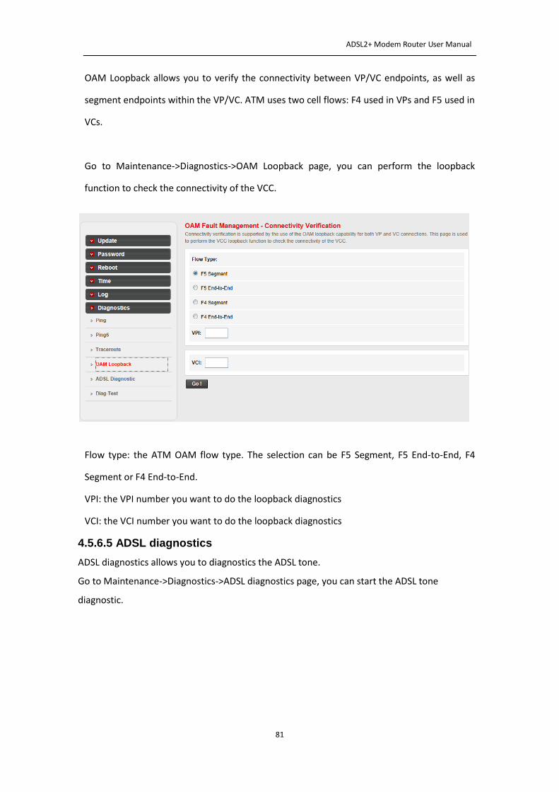
OAM Loopback allows you to verify the connectivity between VP/VC endpoints, as well as
segment endpoints within the VP/VC. ATM uses two cell flows: F4 used in VPs and F5 used in
VCs.
Go to Maintenance->Diagnostics->OAM Loopback page, you can perform the loopback
function to check the connectivity of the VCC.
Flow type: the ATM OAM flow type. The selection can be F5 Segment, F5 End-to-End, F4
Segment or F4 End-to-End.
VPI: the VPI number you want to do the loopback diagnostics
VCI: the VCI number you want to do the loopback diagnostics
4.5.6.5 ADSL diagnostics
ADSL diagnostics allows you to diagnostics the ADSL tone.
Go to Maintenance->Diagnostics->ADSL diagnostics page, you can start the ADSL tone
diagnostic.
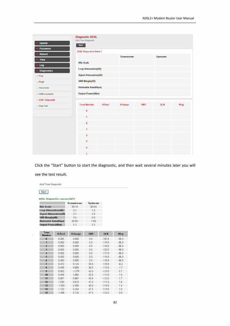
ADSL2+ Modem Router User Manual
82
Click the “Start” button to start the diagnostic, and then wait several minutes later you will
see the test result.
ADSL2+ Modem Router User Manual
83
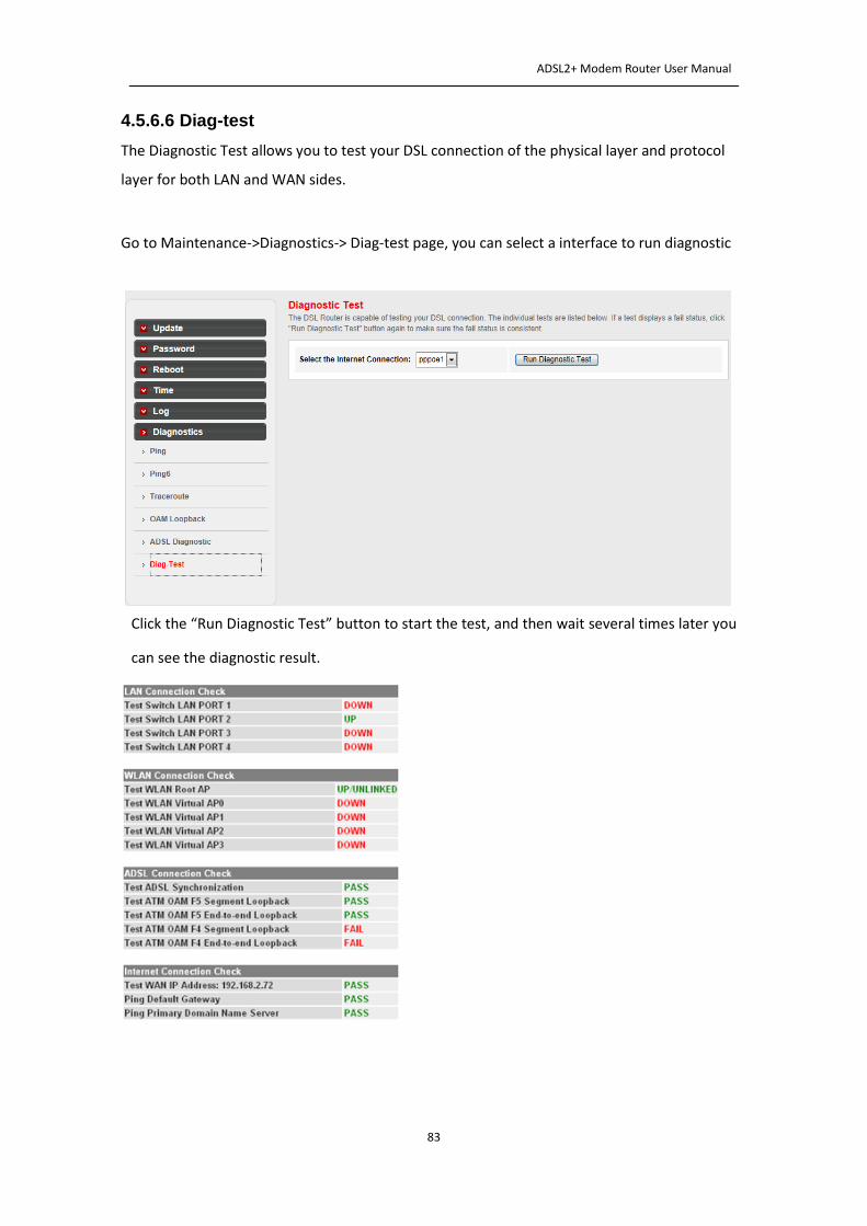
4.5.6.6 Diag-test
The Diagnostic Test allows you to test your DSL connection of the physical layer and protocol
layer for both LAN and WAN sides.
Go to Maintenance->Diagnostics-> Diag-test page, you can select a interface to run diagnostic
Click the “Run Diagnostic Test” button to start the test, and then wait several times later you
can see the diagnostic result.
ADSL2+ Modem Router User Manual
84
Appendix A: Troubleshooting
T1. How do I restore my Modem Router to its factory default settings?
With the Modem Router powered on, press and hold the Reset button on the rear panel for 5
seconds before releasing it.
T2. What can I do if I forgot my password?
1) Restore the Modem Router to factory default settings. If you don’t know how to do it, please
refer to section T1.
2) Use the default user name and password: admin, admin.
3) Configure the Modem Router again since you have ever reset it.
T3. What can I do if I cannot access the Internet?
1) Check to see if all the connectors are connected well, including the telephone line, Ethernet
cable and power adapter.
2) Check to see if you can login to the web management page of the Modem Router. If you can,
try the following steps. If you cannot, please set your computer referring to T4 then try to see if
you can access the Internet.
3) Consult your ISP and make sure all the VPI/VCI、Connection Type and related information are
correct. If there are any mistakes, please correct the settings and try again.
4) If you still cannot access the Internet, please restore your Modem Router and reconfigure it.
T4. Why the LAN’s and the NIC’s LEDs are both bright, but the configuration interface is
inaccessible?
1) Use the order of ping 192.168.1.1 to check the accuracy of connection.
2) If you are using Windows XP, please open the control panel, click network and internet
connections, choose internet options, go to the connection tab, check ‘Never dial up a
connection’.
3) Check the setup of the IP address on your computer. If you disabled the DHCP function, the
IP address can’t be obtained automatically, so you have to specify the IP address for your
computer manually.
ADSL2+ Modem Router User Manual
85
4) Run the ipconfig command in the windows system to check whether the IP address, subnet
mask, and default gateway have been assigned by DHCP.
5) Reset the ADSL Modem to factory default configuration if necessary.
T5.What related parameters are required when you want to access the Internet by ADSL2+
Modem Router?
1) Dial user: Connection type, User name, Password, Value of VPI/VCI, Encapsulation mode.
2) Static IP user: Connection protocol, WAN IP Address, Subnet Mask, Gateway, Value of VPI/VCI,
Encapsulation mode and so on.
T6. Have completed all configurations, but can’t dial through computer
1) Check the indicator of DSL and Internet. It should be acting normally.
2) Check the value of VPI/VCI, Encapsulation mode and so on, and whether you need to install
the dial software, such as Winpoet, Enternet.
3) The PPP dial procedure is inside the product, so you will not need to use the dial software if
your protocol is PPPoA or PPPoE. ADSL Modem will connect automatically.
4) You can check whether your ADSL Modem succeeds in connection or not with PING
command.
T7. Why the wireless stations cannot connect to the Modem Router?
1) Make sure the ‘Enable Wireless Router Radio’ is checked.
2) Make sure that the wireless stations' SSID accord with the Router's SSID.
3) Make sure the wireless stations have right KEY for encryption when the router is encrypted.
4) If the wireless connection is ready, but you can’t access the router, check the IP Address of
your wireless stations.
T8. How to assign a static IP for your computer?
1) For Windows XP, open the control panel, double click network connections, choose local area
connection, right click it and click properties, check ’use the following IP address’ and ‘use the
following DNS server addresses’, enter the network parameter.
2) For Windows 7,open the control panel, double click network and sharing center, click change
adapter settings, choose local area connection, right click it and go to properties, check ‘use the
following IP address’ and ‘use the following DNS server addresses’, enter the network parameter.