Netfinity FAStT500 RAID Controller Enclosure...
91
Transcript of Netfinity FAStT500 RAID Controller Enclosure...


Netfinity FAStT500 RAID Controller Enclosure Unit
User’s Reference

First Edition (April 2000)
INTERNATIONAL BUSINESS MACHINES CORPORATION PROVIDES THIS PUBLICATION “AS IS” WITHOUT WAR-RANTY OF ANY KIND, EITHER EXPRESS OR IMPLIED, INCLUDING, BUT NOT LIMITED TO, THE IMPLIED WAR-RANTIES OF MERCHANTABILITY OR FITNESS FOR A PARTICULAR PURPOSE. Some jurisdictions do not allow disclaimer of express or implied warranties in certain transactions, therefore, this statement may not apply to you.
This publication could include technical inaccuracies or typographical errors. Changes are periodically made to the information herein; these changes will be incorporated in new editions of the publication. IBM may make improvements and/or changes in the product(s) and/or the program(s) described in this publication at any time.
This publication was developed for products and services offered in the United States of America and the United Kingdom. It is possible that this publication may contain references to, or information about, IBM products (machines and programs), program-ming, or services that are not announced in your country. Such references or information must not be construed to mean that IBM intends to announce such IBM products, programming or services in your country.
Requests for technical information about IBM products should be made to your IBM reseller or IBM marketing representative.
No part of this publication may be reproduced or distributed in any form or by any means without prior permission in writing from the International Business Machines Corporation.
© Copyright International Business Machines Corporation 2000. All rights reserved.
Note to U.S. Government Users—Documentation related to restricted rights—Use, duplication or disclosure is subject to restric-tions set forth in GSA ADP Schedule Contract with IBM Corp.
Before using this information and the product it supports, be sure to read the general information under "Appendix. Product warranties and notices" on page 55.

Safety statement
Before installing this product, read the Safety Information book.
Antes de instalar este produto, leia o Manual de Informações sobre Segurança.
Læs hæftet med sikkerhedsforskrifter, før du installerer dette produkt.
Lue Safety Information -kirjanen, ennen kuin asennat tämän tuotteen.
Avant de procéder à l'installation de ce produit, lisez le manuel Safety Information.
Vor Beginn der Installation die Broschüre mit Sicherheitshinweisen lesen.
Prima di installare questo prodotto, leggere l'opuscolo contenente le informazioni sulla sicurezza.
Lees voordat u dit product installeert eerst het boekje met veiligheidsvoorschriften.
Les heftet om sikkerhetsinformasjon (Safety Information) før du installerer dette produktet.
Antes de instalar este produto, leia o folheto Informações sobre Segurança.
Pred instalací tohoto produktu si prectete prírucku bezpecnostních instrukcí.
Przed zainstalowaniem tego produktu należy przeczytać broszurę Informacje DotycząceBezpieczeństwa.
© Copyright IBM Corp. 2000 iii

Antes de instalar este producto, lea la Información de Seguridad.
Läs säkerhetsinformationen innan du installerar den här produkten.
Перед установкой продукта прочтите брошюру по технике безопасности(Safety Information).
Pred inštaláciou tohto produktu si pre ítajte Informa nú brožúrku o bezpe nosti.
Preden namestite ta izdelek, preberite knjižico Varnostne informacije.
Installálás el tt olvassa el a Biztonsági el írások kézikönyvét !
iv IBM Netfinity FAStT500 RAID Controller Enclosure Unit User’s Reference

Electrical safety
To Connect:
1. Turn everything OFF.
2. First, attach all cables to devices.
3. Attach signal cables to connectors.
4. Attach power cords to outlet.
5. Turn device ON.
To Disconnect:
1. Turn everything OFF.
2. First, remove power cords from outlet.
3. Remove signal cables from connectors.
4. Remove all cables from devices.
1
DANGER
Electrical current from power, telephone, and communication cables is hazardous.
To avoid a shock hazard:
– Do not connect or disconnect any cables or perform installation, maintenance, or reconfiguration of this product during an electrical storm.
– Connect all power cords to a properly wired and grounded electrical outlet.
– Connect to properly wired outlets any equipment that will be attached to this product.
– When possible, use one hand only to connect or disconnect signal cables.
– Never turn on any equipment when there is evidence of fire, water, or structural damage.
– Disconnect the attached power cords, telecommunications systems, networks, and modems before you open the device covers, unless instructed otherwise in the installation and configuration procedures.
– Connect and disconnect cables as described in the following table when installing, moving, or opening covers on this product or attached devices.
Safety statement v

CAUTION:When laser products (such as CD-ROMs, DVD drives, fiber optic devices, or transmitters) are installed, note the following:
– Do not remove the covers. Removing the covers of the laser product could result in exposure to hazardous laser radiation. There are no serviceable parts inside the device.
– Use of controls or adjustments or performance of procedures other than those specified herein might result in hazardous radiation exposure.
Class 1 laser statement
DANGER
Some laser products contain an embedded Class 3A or Class 3B laser diode. Note the following.
Laser radiation when open. Do not stare into the beam, do not view directly with optical instruments, and avoid direct exposure to the beam.
3
Class 1 Laser ProductLaser Klasse 1Laser Klass 1Luokan 1 LaserlaiteAppareil A Laser de Classe 1
IEC 825-1:1993 CENELEC EN 60 825
`
vi IBM Netfinity FAStT500 RAID Controller Enclosure Unit User’s Reference

Contents
Safety statement . . . . . . . . . . . . . . . . . . . . . . . . . . . . . . . . . . . . . . . . . . . . . . . . . . . . . . . iiiElectrical safety . . . . . . . . . . . . . . . . . . . . . . . . . . . . . . . . . . . . . . . . . . . . . . . . . . . . . . . . . . . . v
Class 1 laser statement . . . . . . . . . . . . . . . . . . . . . . . . . . . . . . . . . . . . . . . . . . . . . . . . . . . . . . . vi
Contents . . . . . . . . . . . . . . . . . . . . . . . . . . . . . . . . . . . . . . . . . . . . . . . . . . . . . . . . . . . . . vii
Figures . . . . . . . . . . . . . . . . . . . . . . . . . . . . . . . . . . . . . . . . . . . . . . . . . . . . . . . . . . . . . . . xi
Tables . . . . . . . . . . . . . . . . . . . . . . . . . . . . . . . . . . . . . . . . . . . . . . . . . . . . . . . . . . . . . . . xiii
About this book . . . . . . . . . . . . . . . . . . . . . . . . . . . . . . . . . . . . . . . . . . . . . . . . . . . . . . . . xv
How this book is organized . . . . . . . . . . . . . . . . . . . . . . . . . . . . . . . . . . . . . . . . . . . . . . . . . . xv
Notices used in this book . . . . . . . . . . . . . . . . . . . . . . . . . . . . . . . . . . . . . . . . . . . . . . . . . . . . xvi
Related publications . . . . . . . . . . . . . . . . . . . . . . . . . . . . . . . . . . . . . . . . . . . . . . . . . . . . . . . . xvi
Chapter 1. Overview. . . . . . . . . . . . . . . . . . . . . . . . . . . . . . . . . . . . . . . . . . . . . . . . . . . . . 1
Controller unit overview . . . . . . . . . . . . . . . . . . . . . . . . . . . . . . . . . . . . . . . . . . . . . . . . . . . . . 1
Front view . . . . . . . . . . . . . . . . . . . . . . . . . . . . . . . . . . . . . . . . . . . . . . . . . . . . . . . . . . . . . . 1
Back view . . . . . . . . . . . . . . . . . . . . . . . . . . . . . . . . . . . . . . . . . . . . . . . . . . . . . . . . . . . . . . . 2
Fibre Channel connections . . . . . . . . . . . . . . . . . . . . . . . . . . . . . . . . . . . . . . . . . . . . . . . . . . . . 3
Interface ports . . . . . . . . . . . . . . . . . . . . . . . . . . . . . . . . . . . . . . . . . . . . . . . . . . . . . . . . . . . . . 5
Host mini-hubs . . . . . . . . . . . . . . . . . . . . . . . . . . . . . . . . . . . . . . . . . . . . . . . . . . . . . . . . . . . 6
Drive mini-hubs . . . . . . . . . . . . . . . . . . . . . . . . . . . . . . . . . . . . . . . . . . . . . . . . . . . . . . . . . . 6
Ethernet and RS-232 interface ports . . . . . . . . . . . . . . . . . . . . . . . . . . . . . . . . . . . . . . . . . . 7
Chapter 2. Operating the controller unit . . . . . . . . . . . . . . . . . . . . . . . . . . . . . . . . . . . . 9Tasks overview . . . . . . . . . . . . . . . . . . . . . . . . . . . . . . . . . . . . . . . . . . . . . . . . . . . . . . . . . . . . 9
Accessing the controls . . . . . . . . . . . . . . . . . . . . . . . . . . . . . . . . . . . . . . . . . . . . . . . . . . . . . . 11
Turning on the power . . . . . . . . . . . . . . . . . . . . . . . . . . . . . . . . . . . . . . . . . . . . . . . . . . . . . . . 12
Turning off the power . . . . . . . . . . . . . . . . . . . . . . . . . . . . . . . . . . . . . . . . . . . . . . . . . . . . . . 13
Monitoring status through software . . . . . . . . . . . . . . . . . . . . . . . . . . . . . . . . . . . . . . . . . . . . 14
© Copyright IBM Corp. 2000 vii

Checking the indicator lights . . . . . . . . . . . . . . . . . . . . . . . . . . . . . . . . . . . . . . . . . . . . . . . . . 15
Overtemperature condition and power supply shutdown . . . . . . . . . . . . . . . . . . . . . . . . . . . . 22
Turning on the power after an overtemperature shutdown . . . . . . . . . . . . . . . . . . . . . . . . . 23
Turning on the power after an emergency shutdown . . . . . . . . . . . . . . . . . . . . . . . . . . . . . 23
Checking the battery service date . . . . . . . . . . . . . . . . . . . . . . . . . . . . . . . . . . . . . . . . . . . . . . 24
Preparing to move the controller unit . . . . . . . . . . . . . . . . . . . . . . . . . . . . . . . . . . . . . . . . . . . 25
Removing and installing the components . . . . . . . . . . . . . . . . . . . . . . . . . . . . . . . . . . . . . . . . 25
Chapter 3. Replacing controller unit components . . . . . . . . . . . . . . . . . . . . . . . . . . . . 29RAID Controller . . . . . . . . . . . . . . . . . . . . . . . . . . . . . . . . . . . . . . . . . . . . . . . . . . . . . . . . . . . 29
Servicing notes . . . . . . . . . . . . . . . . . . . . . . . . . . . . . . . . . . . . . . . . . . . . . . . . . . . . . . . . . . 29
Replacing a failed controller . . . . . . . . . . . . . . . . . . . . . . . . . . . . . . . . . . . . . . . . . . . . . . . . 30
Installing additional cache memory in a controller . . . . . . . . . . . . . . . . . . . . . . . . . . . . . . . 32
Battery . . . . . . . . . . . . . . . . . . . . . . . . . . . . . . . . . . . . . . . . . . . . . . . . . . . . . . . . . . . . . . . . . . . 35
Servicing notes . . . . . . . . . . . . . . . . . . . . . . . . . . . . . . . . . . . . . . . . . . . . . . . . . . . . . . . . . . 35
Replacing a failed battery . . . . . . . . . . . . . . . . . . . . . . . . . . . . . . . . . . . . . . . . . . . . . . . . . . 35
Controller fan . . . . . . . . . . . . . . . . . . . . . . . . . . . . . . . . . . . . . . . . . . . . . . . . . . . . . . . . . . . . . 39
Servicing notes . . . . . . . . . . . . . . . . . . . . . . . . . . . . . . . . . . . . . . . . . . . . . . . . . . . . . . . . . . 40
Replacing a failed controller fan . . . . . . . . . . . . . . . . . . . . . . . . . . . . . . . . . . . . . . . . . . . . . 40
Fan and communications module . . . . . . . . . . . . . . . . . . . . . . . . . . . . . . . . . . . . . . . . . . . . . . 42
Servicing notes . . . . . . . . . . . . . . . . . . . . . . . . . . . . . . . . . . . . . . . . . . . . . . . . . . . . . . . . . . 42
Replacing a failed fan and communications module . . . . . . . . . . . . . . . . . . . . . . . . . . . . . 43
Power supply . . . . . . . . . . . . . . . . . . . . . . . . . . . . . . . . . . . . . . . . . . . . . . . . . . . . . . . . . . . . . 45
Servicing notes . . . . . . . . . . . . . . . . . . . . . . . . . . . . . . . . . . . . . . . . . . . . . . . . . . . . . . . . . . 45
Replacing a failed power supply . . . . . . . . . . . . . . . . . . . . . . . . . . . . . . . . . . . . . . . . . . . . . 46
Mini-hubs . . . . . . . . . . . . . . . . . . . . . . . . . . . . . . . . . . . . . . . . . . . . . . . . . . . . . . . . . . . . . . . . 48
Servicing notes . . . . . . . . . . . . . . . . . . . . . . . . . . . . . . . . . . . . . . . . . . . . . . . . . . . . . . . . . . 49
Replacing a failed mini-hub . . . . . . . . . . . . . . . . . . . . . . . . . . . . . . . . . . . . . . . . . . . . . . . . 49
GBICs . . . . . . . . . . . . . . . . . . . . . . . . . . . . . . . . . . . . . . . . . . . . . . . . . . . . . . . . . . . . . . . . . . . 51
Servicing notes . . . . . . . . . . . . . . . . . . . . . . . . . . . . . . . . . . . . . . . . . . . . . . . . . . . . . . . . . . 51
Replacing a failed GBIC . . . . . . . . . . . . . . . . . . . . . . . . . . . . . . . . . . . . . . . . . . . . . . . . . . . 52
Appendix. Product warranties and notices . . . . . . . . . . . . . . . . . . . . . . . . . . . . . . . . . 55
Warranty statements . . . . . . . . . . . . . . . . . . . . . . . . . . . . . . . . . . . . . . . . . . . . . . . . . . . . . . . . 55
viii IBM Netfinity FAStT500 RAID Controller Enclosure Unit User’s Reference

Notices . . . . . . . . . . . . . . . . . . . . . . . . . . . . . . . . . . . . . . . . . . . . . . . . . . . . . . . . . . . . . . . . . . 63
Trademarks . . . . . . . . . . . . . . . . . . . . . . . . . . . . . . . . . . . . . . . . . . . . . . . . . . . . . . . . . . . . . 63
Electronic emissions statements . . . . . . . . . . . . . . . . . . . . . . . . . . . . . . . . . . . . . . . . . . . . . . . 64
Federal Communications Commission (FCC) Statement . . . . . . . . . . . . . . . . . . . . . . . . . 64
Industry Canada Class A emission compliance statement . . . . . . . . . . . . . . . . . . . . . . . . . 64
United Kingdom telecommunications safety requirements . . . . . . . . . . . . . . . . . . . . . . . . 64
European community directive conformance statement . . . . . . . . . . . . . . . . . . . . . . . . . . 64
Australia and New Zealand Class A statement . . . . . . . . . . . . . . . . . . . . . . . . . . . . . . . . . 65
Taiwanese electromagnetic interference (EMI) statement . . . . . . . . . . . . . . . . . . . . . . . . . 65
Power cords . . . . . . . . . . . . . . . . . . . . . . . . . . . . . . . . . . . . . . . . . . . . . . . . . . . . . . . . . . . . . . 65
Index. . . . . . . . . . . . . . . . . . . . . . . . . . . . . . . . . . . . . . . . . . . . . . . . . . . . . . . . . . . . . . . . . 67
Contents ix

x IBM Netfinity FAStT500 RAID Controller Enclosure Unit User’s Reference

Figures
Figure 1. IBM Netfinity FAStT500 RAID Controller Enclosure Unit – front view . . . . . 2
Figure 2. IBM Netfinity FAStT500 RAID Controller Enclosure Unit – back view . . . . . 3
Figure 3. Fibre Channel interface connections . . . . . . . . . . . . . . . . . . . . . . . . . . . . . . . . . . 3
Figure 4. Host side and drive side mini-hub ports (back view) . . . . . . . . . . . . . . . . . . . . . 6
Figure 5. Ethernet and RS-232 interface ports . . . . . . . . . . . . . . . . . . . . . . . . . . . . . . . . . . 7
Figure 6. Removing the controller unit bezel . . . . . . . . . . . . . . . . . . . . . . . . . . . . . . . . . . 11
Figure 7. Replacing the controller unit bezel . . . . . . . . . . . . . . . . . . . . . . . . . . . . . . . . . . 11
Figure 8. Turning on and off the power . . . . . . . . . . . . . . . . . . . . . . . . . . . . . . . . . . . . . . 12
Figure 9. Indicator lights (front) . . . . . . . . . . . . . . . . . . . . . . . . . . . . . . . . . . . . . . . . . . . . 16
Figure 10. Controller unit indicator lights — back view . . . . . . . . . . . . . . . . . . . . . . . . . 18
Figure 11. Mini-hub indicator lights. . . . . . . . . . . . . . . . . . . . . . . . . . . . . . . . . . . . . . . . . 19
Figure 12. Fan and communications and power supply fault indicators . . . . . . . . . . . . . 22
Figure 13. Overtemperature indicator. . . . . . . . . . . . . . . . . . . . . . . . . . . . . . . . . . . . . . . . 22
Figure 14. Checking the battery service date . . . . . . . . . . . . . . . . . . . . . . . . . . . . . . . . . . 24
Figure 15. Controller indicator lights . . . . . . . . . . . . . . . . . . . . . . . . . . . . . . . . . . . . . . . . 29
Figure 16. Removing and installing a controller CRU . . . . . . . . . . . . . . . . . . . . . . . . . . . 31
Figure 17. Indicator lights on the controller unit bezel. . . . . . . . . . . . . . . . . . . . . . . . . . . 32
Figure 18. Recording the battery support information . . . . . . . . . . . . . . . . . . . . . . . . . . . 36
Figure 19. Removing and installing a battery. . . . . . . . . . . . . . . . . . . . . . . . . . . . . . . . . . 37
Figure 20. Battery CRU indicator lights . . . . . . . . . . . . . . . . . . . . . . . . . . . . . . . . . . . . . . 38
Figure 21. Controller unit airflow. . . . . . . . . . . . . . . . . . . . . . . . . . . . . . . . . . . . . . . . . . . 39
Figure 22. Removing and installing the controller fan . . . . . . . . . . . . . . . . . . . . . . . . . . . 41
Figure 23. Controller fan indicator lights . . . . . . . . . . . . . . . . . . . . . . . . . . . . . . . . . . . . . 41
Figure 24. Fan and communications module ports and indicator light . . . . . . . . . . . . . . 43
© Copyright IBM Corp. 2000 xi

Figure 25. Removing and installing a fan and communications module . . . . . . . . . . . . . 44
Figure 26. Power supply switch, ac power connectors, and indicator lights . . . . . . . . . . 46
Figure 27. Removing and installing a power supply CRU . . . . . . . . . . . . . . . . . . . . . . . . 48
Figure 28. Removing and installing a mini-hub . . . . . . . . . . . . . . . . . . . . . . . . . . . . . . . . 50
xii IBM Netfinity FAStT500 RAID Controller Enclosure Unit User’s Reference

Tables
Table 1. Tasks overview . . . . . . . . . . . . . . . . . . . . . . . . . . . . . . . . . . . . . . . . . . . . . . . . . . 9
Table 2. Indicator lights (front) . . . . . . . . . . . . . . . . . . . . . . . . . . . . . . . . . . . . . . . . . . . . 16
Table 3. Indicator lights (back) . . . . . . . . . . . . . . . . . . . . . . . . . . . . . . . . . . . . . . . . . . . . 19
Table 4. Mini-hub indicator lights (back) . . . . . . . . . . . . . . . . . . . . . . . . . . . . . . . . . . . . 20
© Copyright IBM Corp. 2000 xiii

xiv IBM Netfinity FAStT500 RAID Controller Enclosure Unit User’s Reference

About this book
This book gives an overview of the IBM® Netfinity® FAStT500 RAID Controller Enclosure Unit and provides information about routine operations and replacement procedures for all customer-replaceable units (CRUs). This User’s Reference is intended for system operators and service technicians who have extensive knowledge of Fibre Channel and network technology, and computer system operation, maintenance, and repair. Use this guide to:
• Become familiar with the components of the controller unit
• Learn the tasks required to maintain the controller unit on a daily basis
• Learn how to replace failed components in the controller unit
Before using this book, you must install the hardware and software. For more information, refer to the IBM Netfinity FAStT500 RAID Controller Enclosure Unit Installation Guide and the IBM Netfinity FAStT Storage Manager for Windows NT Installation and Support Guide that come with the controller unit.
How this book is organized
"Chapter 1. Overview" introduces the controller unit and its primary components.
"Chapter 2. Operating the controller unit" describes the tasks required to operate the controller unit.
"Chapter 3. Replacing controller unit components" describes the controller components and gives servicing information and replacement procedures.
"Appendix. Product warranties and notices" provides warranty statements and product notices.
© Copyright IBM Corp. 2000 xv

Notices used in this book
This book contains notices to highlight information or provide safety information:
• Note
These notices provide important tips, guidance, or advice.
• Attention
These notices indicate possible damage to programs, devices, or data. An attention notice is placed just before the instruction or situation in which damage could occur.
• CAUTION
These notices indicate situations that can be potentially hazardous to you. A caution notice is placed just before descriptions of potentially hazardous procedure steps or situations.
• DANGER
These notices indicate situations that are potential lethal or extremely hazardous to you. A danger notice is placed just before descriptions of potentially lethal or extremely hazardous procedure steps or situations.
Related publications
The following publications are available in Adobe® Acrobat® Portable Document Format (PDF) on the IBM Netfinity FAStT Storage Manager CD and on the World Wide Web at http://www.ibm.com/pc/support/
Note: The items denoted by an asterisk (*) in the list indicate publications that are printed and come with the IBM Netfinity FAStT500 RAID Controller Enclosure Unit.
• IBM Netfinity FAStT500 RAID Controller Enclosure Unit Installation Guide*
• IBM Netfinity FAStT500 RAID Controller Enclosure Unit User’s Reference (this book)
• IBM Netfinity FAStT Storage Manager for Windows NT Installation and Support Guide*
• IBM Netfinity Fibre Channel Storage Manager Concepts Guide
xvi IBM Netfinity FAStT500 RAID Controller Enclosure Unit User’s Reference

Additional publications are available for purchase from IBM. For a list of publications available in your country:
• In the U.S. and Puerto Rico, call 1-800-426-7282.
• In the United Kingdom, call 01705-565000 or 0161-9056001.
• In Canada, call 1-800-465-1234.
• In other countries, contact the IBM support organization that services your area, your IBM marketing representative, or your IBM reseller.
About this book xvii

xviii IBM Netfinity FAStT500 RAID Controller Enclosure Unit User’s Reference

Chapter 1. Overview
The IBM Netfinity FAStT500 RAID Controller Enclosure Unit (referred to throughout this book as controller unit) is a high-performance unit that provides dual, redundant RAID controllers and Fibre Channel interfaces to both the host and drive channels.
Controller unit overview
The controller unit supports direct attachment of up to four hosts containing two host adapters each, and is designed to provide maximum host- and drive-side redundancy. Using an external hub, the controller unit can support up to 64 host adapters per controller (up to 128 host adapters per controller unit).
Each controller unit contains several removable components, called customer replaceable units (CRUs), that you can access from either the front or back of the unit. These CRUs include the battery, RAID controllers, controller fan, power supplies, fan and communications module, mini-hubs, and Gigabit Interface Converters (GBICs). The controller unit also has a removable front bezel.
Front view
Figure 1 on page 2 shows the controller unit front view and the following components:
• Bezel – Removable front cover with holes for viewing the status lights and for boosting air circulation.
• Controller fan – One removable unit that contains two cooling fans and status indicator lights.
• Battery – One removable unit that contains a battery and battery charger circuitry.
• Controllers – Two removable units, each contains one RAID controller.
© Copyright IBM Corp. 2000 1

Figure 1. IBM Netfinity FAStT500 RAID Controller Enclosure Unit – front view
Back view
Figure 2 on page 3 shows the controller unit back view and the following components:
• Host side and drive side mini-hubs – Up to eight removable mini-hubs to which you can connect GBICs and fiber-optic host and drive interface cables for the controller unit.
• Power supplies – Two removable units that contain the power supplies.
• Fan and communications module – One removable unit that contains the power supply cooling fans, Ethernet ports, and RS-232 (serial) ports.
Removablebezel
Controllerfan
Controllers
Battery
2 IBM Netfinity FAStT500 RAID Controller Enclosure Unit User’s Reference

Figure 2. IBM Netfinity FAStT500 RAID Controller Enclosure Unit – back view
Fibre Channel connections
When fully configured, the back of the controller unit can accommodate up to four host side and four drive side mini-hubs. Each mini-hub is a single, removable unit that provides the Fibre Channel interface between a controller unit and hosts and drives. Each mini-hub has two GBIC ports. One Gigabit Interface Converter (GBIC) connects into each mini-hub port. Figure 3 shows the Fibre Channel components.
Figure 3. Fibre Channel interface connections
Host side mini-hubs Fan and communications
module
Power supply Power supply
Drive side mini-hubs
Fiber-opticinterface cable
GBIC
Mini-hub
Host mini-hub ports
GBIC
Drive mini-hub ports
Chapter 1. Overview 3

CAUTION:When laser products (such as CD-ROMs, DVD drives, fiber optic devices, or transmitters) are installed, note the following:
– Do not remove the covers. Removing the covers of the laser product could result in exposure to hazardous laser radiation. There are no serviceable parts inside the device.
– Use of controls or adjustments or performance of procedures other than those specified herein might result in hazardous radiation exposure.
Attention: To avoid damage to your fiber-optic cables, follow these guidelines:
• Do not route the cable along a folding cable management arm.
• When attaching to a device on slides, leave enough slack in the cable so that it does not bend to a radius smaller than 76 mm (3 inches) when extended or become pinched when retracted.
• Route the cable away from places where it can be snagged by other devices in the rack.
• Do not overtighten the cable straps or bend the cables to a radius smaller than 76 mm (3 inches).
• Do not put excess weight on the cable at the connection point and be sure that it is well supported.
DANGER
Some laser products contain an embedded Class 3A or Class 3B laser diode. Note the following.
Laser radiation when open. Do not stare into the beam, do not view directly with optical instruments, and avoid direct exposure to the beam.
3
4 IBM Netfinity FAStT500 RAID Controller Enclosure Unit User’s Reference

To connect the fiber-optic cables, do the following.
1 Remove the two protective caps from one end of the fiber-optic cable.
2 Connect the fiber-optic cable to a GBIC that is installed in a mini-hub.
After installing the cables, the Fibre Channel Arbitrated Loop is operational.
For information about replacing mini-hubs, see "Mini-hubs" on page 48. For information about replacing GBICs, see "GBICs" on page 51.
Interface ports
The controller unit has the following types of interface ports:
• Host
• Drive
• Ethernet
• RS-232 (serial)
Protective capFiber-opticcable
GBIC
Fiber-opticcable
Chapter 1. Overview 5

The following figure shows the host and drive mini-hub ports.
Figure 4. Host side and drive side mini-hub ports (back view)
For more information about connecting the controller unit and drive enclosures (also referred to as expansion units) using the host and drive interface ports, refer to the IBM Netfinity FAStT500 RAID Controller Enclosure Unit Installation Guide.
Host mini-hubs
There are up to four host side mini-hubs, two per controller (see Figure 4). Mini-hubs 1 and 3 correspond to the top controller (Controller A) and mini-hubs 2 and 4 correspond to the bottom controller (Controller B). Each pair of mini-hubs accommodates one host channel. Each mini-hub provides host loop connectivity and self-diagnostic features. To ensure redundancy, you must connect each host to a Controller A and Controller B mini-hub.
Drive mini-hubs
The controller unit has four drive channels. Each channel accommodates one drive side mini-hub (see Figure 4). All mini-hubs on the drive side attach to both Controller A and Controller B.
Drive side mini-hubs
Host side mini-hubs
Controller BController BController A
1 3 4
Controller A
2 1234
Host GBICmini-hub
ports
Drive GBIC mini-hub ports
6 IBM Netfinity FAStT500 RAID Controller Enclosure Unit User’s Reference

Ethernet and RS-232 interface ports
Each controller has an Ethernet interface port and an RS-232 (serial) interface port. Use the Ethernet ports if you want to directly manage the controllers. Use the RS-232 ports for diagnostic service. Figure 5 shows the location of these interface ports.
Figure 5. Ethernet and RS-232 interface ports
Controller B
Ethernet portsRS-232 ports
Controller A Controller B Controller A
Chapter 1. Overview 7

8 IBM Netfinity FAStT500 RAID Controller Enclosure Unit User’s Reference

Chapter 2. Operating the controller unit
This chapter describes the tasks required to operate the controller unit.
Tasks overview
Perform the tasks shown in Table 1 to maintain the controller unit after it is installed.
Table 1: Tasks overview
Task Description See
Accessing the controls To access the controller CRUs, battery, controller fan, and indicator lights, you must remove the controller unit bezel.
"Accessing the controls" on page 11
Turning on or off the power The controller unit usually runs continuously. However, you might need to turn off and on the power to move the controller unit or to perform maintenance procedures.
"Turning on the power" on page 12 and "Turning off the power" on page 13
Monitoring controller unit status through software
Run the storage-management software continuously. This software checks the storage subsystem for failures and displays messages indicating the type of failure and the recovery procedure.
"Monitoring status through software" on page 14
Checking fault indicator lights for component failures
Component failures are indicated by lights on the front and back of the controller unit and are monitored by the storage-management software.
Note: The indicator lights identify problems with the controller unit components, but you might need more information to thoroughly diagnose and repair the unit. Therefore, it is important to use the storage-management software to continuously monitor the status of the controller unit.
"Checking the indicator lights" on page 15
© Copyright IBM Corp. 2000 9

Restoring power after a power supply shutdown
If the controller unit shuts down because of a power supply overtemperature condition, you must take special care when restarting it.
"Overtemperature condition and power supply shutdown" on page 22
Checking the battery service date
Periodically check the battery service date information. Replace the battery whenever it fails to hold a charge or every three years.
Note: Using the controller unit in a hot environment that is above 35º C (or 95º F), lowers the battery life expectancy. Under these conditions, you might need to replace the battery more often.
"Checking the battery service date" on page 24
Preparing to move the controller unit
You might need to move the controller unit to a new location or remove the chassis from its cabinet.
"Preparing to move the controller unit" on page 25
Table 1: Tasks overview
Task Description See
10 IBM Netfinity FAStT500 RAID Controller Enclosure Unit User’s Reference

Accessing the controls
To access the controllers, battery, controller fan, and indicator lights, you must remove the controller unit bezel, as shown in Figure 6.
Attention: Pulling the cover out too far can damage the plastic hooks at the top. To avoid damaging the hooks, place the controller unit on a flat surface. Be sure the front of the controller unit extends beyond the edge approximately 5 cm (2 in.).
1 Carefully pull the bottom of the bezel out to release the pins; then slide the bezel down, as shown in the following figure.
Figure 6. Removing the controller unit bezel
2 To replace the bezel, slip the top edge of the bezel under the lip on the chassis, then push the bottom of the bezel until the pins snap into the mounting holes, as shown in the following figure.
Figure 7. Replacing the controller unit bezel
Bezel
Bezel
Chapter 2. Operating the controller unit 11

Turning on the power
Use the following procedure to turn on power to the controller unit. If you are restoring power to the controller unit after an emergency shutdown or power outage, go to "Overtemperature condition and power supply shutdown" on page 22.
Important: You must turn on the drive enclosures before, or at the same time as, the controller unit. The controllers might not recognize the correct configuration if the attached drives are powered up after the controller unit. If you plan to use the main breaker to turn on all enclosures at the same time, make sure that the switches on each drive enclosure and each controller unit are on before turning on the main breaker. For instructions on powering up the drive enclosures, refer to the drive enclosure documentation.
Note: Always wait at least 30 seconds between the time you turn off a power switch and the time you turn on the power again.
Turn on both power switches on the back of the controller unit (see Figure 8). You must turn on both switches to take advantage of the redundant power supplies. Then, go to "Checking the indicator lights" on page 15.
Figure 8. Turning on and off the power
ac power cord
Power switch
Power switch
ac power cord
12 IBM Netfinity FAStT500 RAID Controller Enclosure Unit User’s Reference

Turning off the power
CAUTION:The Power Control button on the device and the power switch on the power supply do not turn off the electrical current supplied to the device. The device also might have more than one power cord. To remove all electrical current from the device, ensure that all power cords are disconnected from the power source.
Attention: The controller unit is designed to run continuously, 24 hours a day. Except in an emergency, never turn off the power if any controller unit fault indicator lights are lit. Use the proper troubleshooting or servicing procedure to correct the fault before turning off the power. This ensures that the controller unit powers up correctly later. For more information, see "Checking the indicator lights" on page 15.
Use the following procedure to turn off power to the controller unit.
1 Prepare the controller unit for shutdown, as follows:
a Stop all I/O activity to the controller unit and attached drive enclosures. Logically disconnect the controller and drive enclosures from the hosts. Make sure that the fast write cache indicator light on each controller unit front panel and all applicable drive active indicator lights on each drive enclosure front panel are off (not blinking).
Note:If a parity check is in progress, it can take a long time for the drive indicator lights to stop blinking.
b Make sure that all amber fault indicator lights on the controller unit are off. If any fault indicator lights are on, correct the problem before turning off the power. For more information, see "Checking the indicator lights" on page 15.
5
1
2
Chapter 2. Operating the controller unit 13

2 Turn off the power switches on the back of the controller unit (see Figure 8 on page 12).
3 Turn off any drive enclosures attached to the controller unit.
Monitoring status through software
To monitor controller unit status, always run the storage-management software and check it frequently. Be sure to enable the management alerts that you need. The storage-management software provides the best way to diagnose and repair controller unit failures. This software can help you:
• Determine the nature of the failure
• Locate the failed component
• Provide recovery procedures to repair the failure
Although the controller unit has fault indicators, these lights are summary indicators and might not identify the specific component that has failed or needs replacing, or which type of recovery procedure you must perform. In some cases (such as loss of redundancy in controller unit components), the fault light does not come on. Only the storage-management software can detect the failure.
Recovering from a controller unit failure might require you to perform procedures other than replacing the component. The storage-management software gives these procedures.
Note: Always follow the software recovery procedures to prevent data loss.
For more information about the storage-management software, refer to the following:
• IBM Netfinity FAStT Storage Manager for Windows NT Installation and Support Guide
• IBM Netfinity Fibre Channel Storage Manager Concepts Guide
• The following IBM Netfinity FAStT Storage Manager online help is available:
• Enterprise Management Online Help
• Subsystem Management Online Help
14 IBM Netfinity FAStT500 RAID Controller Enclosure Unit User’s Reference

Checking the indicator lights
The controller unit indicator lights display the status of the controller unit and its components. Green indicator lights mean normal operating status; amber indicator lights mean a possible failure.
It is important that you check all the indicator lights on the front and back of the controller unit when you turn on the power. After you turn on the power, the indicator lights might blink intermittently. Wait until the controller unit completes its power up before checking for faults. It can take up to 15 minutes for the battery to complete its self-test and up to 24 hours to fully charge, particularly after an unexpected power loss of more than a few minutes.
Use the following procedure to check the controller unit indicator lights and operating status.
1 To view the indicator lights, remove the controller unit bezel, as shown in Figure 6 on page 11.
2 Check the indicator lights on the front of the controller unit. The indicator lights are shown in Figure 9 on page 16 and described in Table 2 on page 16.
3 Check the indicator lights on the back of the controller unit, as shown in Figure 10 on page 18 and described in Table 3 on page 19.
4 Check the indicator lights on the mini-hubs, as shown in Figure 11 on page 19 and described in Table 4 on page 20.
5 If all indicator lights show a normal status, replace the bezel; otherwise, run the storage-management software to diagnose and repair the problem.
Chapter 2. Operating the controller unit 15

Figure 9. Indicator lights (front)
Table 2: Indicator lights (front)
Indicator light
ColorNormal
operationProblem indicator
Possible conditions indicated by the
problem indicator1
Component: controller CRU
Power Green On Off • No power to controller unit
• No power to storage subsystem
• Cables are loose or the switches are off
• Power supply has failed, is missing, or is not fully seated
• Overtemperature condition
Fault Amber Off On Controller failure; controller fault condition
Heartbeat Green Blinking2 Not blinking2
No controller activity
Status(eight lights including Heartbeat)
Green Various patterns depending on the condition
Various patterns depending on the condition
If the second, third, sixth, and seventh lights are on or if all eight lights are on, there is a memory fault indicating that the controller CRU has failed.
Power
Fault-BFull Charge-B Fault-A
Power
Fault Heartbeat
Full Charge-A
Fast write cache
Controller
Controller fan
Power supply
16 IBM Netfinity FAStT500 RAID Controller Enclosure Unit User’s Reference

Component: controller fan
Power Green On Off • No power to controller unit
• No power to storage subsystem
• Cables are loose or the switches are off
• Power supply has failed, is missing, or is not fully seated in controller unit
• Overtemperature condition
Power supply fault
Amber Off On • Power supply has failed
• Overtemperature
• Power supply is turned off, disconnected, or not fully seated in controller unit
• No power to controller unit or storage subsystem (all indicator lights are off)
Controller fan fault
Amber Off On • Controller fan has failed
• Fan and communications module is missing, unplugged, or has failed
• Circuitry failure
• Overtemperature condition.
Controller fault
Amber Off On Controller has failed; one or more memory modules failed (SIMMs or DIMMs)
Fast write cache
Green Steady or blinking3
Software dependent3
Normal operation is off if:
• Cache is not enabled
• Battery is not ready
Table 2: Indicator lights (front)
Indicator light
ColorNormal
operationProblem indicator
Possible conditions indicated by the
problem indicator1
Chapter 2. Operating the controller unit 17

The indicator lights on the back of the controller unit are shown in Figure 10 and are described in Table 3.
Figure 10. Controller unit indicator lights — back view
Component: battery
Fault-A or Fault-B
Amber Off On • Left or right battery bank has failed
• Battery is either discharged or defective
Full Charge-A or Full Charge-B
Green On4 Off • Left or right battery bank is not fully charged
• Power has been off for an extended period and has drained battery power
• Batteries are weak
1 Always use the storage-management software to identify the failure.
2 There are eight status lights (the Heartbeat and seven others) that glow in various patterns, depending on the controller status.
3 The fast write cache indicator light is on when there is data in cache and blinks during a fast write operation.
4 If either Full Charge-A or Full Charge-B indicator light blink, the battery is in the process of charging.
Table 2: Indicator lights (front)
Indicator light
ColorNormal
operationProblem indicator
Possible conditions indicated by the
problem indicator1
Fan and communications module fault
Power supply faultPower supply fault
18 IBM Netfinity FAStT500 RAID Controller Enclosure Unit User’s Reference

The mini-hub indicator lights on the back of the controller unit are shown in Figure 11 and described in Table 4 on page 20.
Figure 11. Mini-hub indicator lights
Table 3: Indicator lights (back)
Indicator light ColorNormal
operationProblem indicator
Possible conditions indicated by the
problem indicator1
Fan and communications module
Fan and communication fault
Amber Off On • Fan and communications module has failed or is installed incorrectly
• Overtemperature condition
Power supply
Power supply Green On Off • No power to controller unit
• No power to storage subsystem
• Power supply has failed
• Overtemperature condition
1 Always use the storage-management software to identify the failure.
OU
TIN
Mini-hub indicator lights
Fault
Bypass(upper port)
Loop good
Bypass(lower port)
Chapter 2. Operating the controller unit 19
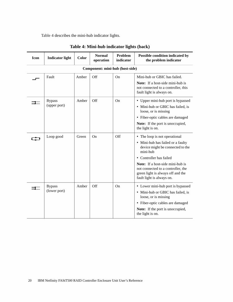
Table 4 describes the mini-hub indicator lights.
Table 4: Mini-hub indicator lights (back)
Icon Indicator light ColorNormal
operationProblem indicator
Possible condition indicated by the problem indicator
Component: mini-hub (host-side)
Fault Amber Off On Mini-hub or GBIC has failed.
Note: If a host-side mini-hub is not connected to a controller, this fault light is always on.
Bypass(upper port)
Amber Off On • Upper mini-hub port is bypassed
• Mini-hub or GBIC has failed, is loose, or is missing
• Fiber-optic cables are damaged
Note: If the port is unoccupied, the light is on.
Loop good Green On Off • The loop is not operational
• Mini-hub has failed or a faulty device might be connected to the mini-hub
• Controller has failed
Note: If a host-side mini-hub is not connected to a controller, the green light is always off and the fault light is always on.
Bypass(lower port)
Amber Off On • Lower mini-hub port is bypassed
• Mini-hub or GBIC has failed, is loose, or is missing
• Fiber-optic cables are damaged
Note: If the port is unoccupied, the light is on.
20 IBM Netfinity FAStT500 RAID Controller Enclosure Unit User’s Reference

Component: mini-hub (drive-side)
Fault Amber Off On Mini-hub or GBIC has failed.
Note: If a drive-side mini-hub is not connected to a controller, this fault light is always on.
Bypass(upper port)
Amber Off On • Upper mini-hub port is bypassed
• Mini-hub or GBIC has failed, is loose, or is missing
• Fiber-optic cables are damaged
Note: If the port is unoccupied, the light is on.
Loop good Green On Off • The loop is not operational
• Mini-hub has failed or a faulty device might be connected to the mini-hub
• Drive has failed
Note: If a drive-side mini-hub is not connected to a controller, the green light is always off and the fault light is always on.
Bypass(lower port)
Amber Off On • Lower mini-hub port is bypassed
• Mini-hub or GBIC has failed, is loose, or is missing
• Fiber-optic cables are damaged
Note: If the port is unoccupied, the light is on.
Table 4: Mini-hub indicator lights (back)
Icon Indicator light ColorNormal
operationProblem indicator
Possible condition indicated by the problem indicator
Chapter 2. Operating the controller unit 21

Overtemperature condition and power supply shutdown
If the fan and communications module fails or is unable to maintain an internal temperature below 70o C (158o F), one or both of the power supplies in the controller unit might shut down (see Figure 12). If both power supplies shut down, the controller unit is not operational.
Figure 12. Fan and communications and power supply fault indicators
The storage-management software causes the fault indicator to light before the temperature has risen sufficiently to shut down the power supplies. The light comes on when the controller unit temperature exceeds 45° C (113° F). The controller unit shuts down if the temperature rises to 70° C (158° F). See Figure 13 for the location of the controller fan fault indicator. If both power supplies shut down, the fault indicator cannot come on.
Figure 13. Overtemperature indicator
Fan and communications fault
indicator
Fan and communications
module
Power supplies
Power supply fault indicators
Controller fan fault indicator
22 IBM Netfinity FAStT500 RAID Controller Enclosure Unit User’s Reference

Turning on the power after an overtemperature shutdown
If your controller unit shuts down unexpectedly, use the storage-management software to determine if the controller unit is overheated. If an overtemperature shutdown is indicated, use the following procedure to regain normal system operation.
1 Turn off the power switches and cool the controller unit (for example, replace the fans, use external fans to cool the room, and so on).
2 Once the air temperature is below the upper operating temperature of 45° C (113° F), turn on the power switches.
3 Check the controller unit for faults or damage. Use the storage-management software to check the overall status of the controller unit and its components. Repair any faults found.
Turning on the power after an emergency shutdown
Use this procedure to regain normal system operation after a power failure or emergency shutdown.
1 After the emergency situation is over or power is restored to the building, check all components and cables for damage. If there is no visible damage, continue with Step 2; otherwise, have your system serviced.
2 Make sure the power cords are plugged in.
3 Turn on the circuit breakers in the cabinet and turn on the power switches on all drive enclosures attached to the controller unit. If the system is off because of a power outage, the power switches are already on.
Important: You must turn on the drive enclosures before, or at the same time as, the controller unit. The controllers might not recognize the correct configuration if the attached drives are powered up after the controller unit. If you plan to use the main breaker to turn on all enclosures at the same time, make sure that the switches on each drive enclosure and each controller unit are on before turning on the main breaker. For instructions on powering up the drive enclosures, refer to the drive enclosure documentation.
4 Turn on both power switches on the back of the controller unit (see Figure 8 on page 12).
5 Check the status of the controller unit and other devices. Make sure all fault indicator lights are off on the front and back of the controller unit. For more information, see "Checking the indicator lights" on page 15.
6 When all the devices on the system are powered up, check the overall system status using the storage-management software.
Chapter 2. Operating the controller unit 23

Checking the battery service date
Note: Replace the battery whenever it fails to hold a charge or every three years. Using the controller unit in a hot environment (above 35º C or 95º F) lowers the battery life expectancy. Under these conditions, you might need to replace the battery more often.
To check the battery service date, do the following:
1 Remove the controller unit bezel, as shown in Figure 6 on page 11.
2 Check the Battery Support Information label, as shown in the following figure.
Figure 14. Checking the battery service date
The Battery Support Information label on the front of the battery has three dates:
• Date of Manufacture – Date the battery was built at the factory
• Date of Installation – Date the battery was installed in the controller unit
• Replacement Date – Date to replace the battery (see the note at the beginning of this section)
3 Look at the replacement date and do the following:
• If it is time to replace the battery, install a new battery using the procedure described in "Replacing a failed battery" on page 35.
• If it is not time to replace the battery, replace the controller unit bezel, as shown in Figure 7 on page 11.
24 IBM Netfinity FAStT500 RAID Controller Enclosure Unit User’s Reference

Preparing to move the controller unit
Remove each component CRU before moving the controller unit to a new location or before removing the chassis from its cabinet. This helps safeguard the equipment and ensures a smoother transition to the new environment.
If you are moving the controller unit a short distance (within the same building), and you have sufficient assistance (one or more additional helpers) or equipment (such as a fork lift), you might be able to move the controller unit without removing each component CRU. If you do not have sufficient assistance or equipment, use the procedure in "Removing and installing the components" to safely move the equipment to its new location.
If you are moving the controller unit a significant distance (for example, to another building or city), be sure to pack it in its original shipping container.
For more information about assembling or disassembling the controller unit, refer to the IBM Netfinity FAStT500 RAID Controller Enclosure Unit Installation Guide.
Removing and installing the components
Use the following procedure to remove all component CRUs before moving or relocating the controller unit. Replace the CRUs after you complete the procedure.
1 Prepare the controller unit for shutdown, as follows:
a Stop all I/O activity to the controller unit and attached drive enclosures.
b Logically disconnect the controller and drive enclosures from the hosts.
c Make sure that the fast write cache indicator light on the front bezel is off (not blinking).
d Make sure that all applicable drive active indicator lights on each drive enclosure front panel are off (not blinking).
Note: If a parity check is in progress, it can take a long time for the drive indicator lights to stop blinking.
2 Remove the controller unit bezel, as shown in Figure 6 on page 11.
3 Make sure that all amber fault indicator lights on the controller unit are off. If any fault indicator lights are on, correct the problem before turning off the power. For more information, see "Checking the indicator lights" on page 15.
Chapter 2. Operating the controller unit 25
CAUTION:The Power Control button on the device and the power switch on the power supply do not turn off the electrical current supplied to the device. The device also might have more than one power cord. To remove all electrical current from the device, ensure that all power cords are disconnected from the power source.
4 Turn off both power switches and unplug the power cords from the controller unit, as shown in Figure 8 on page 12.
5 If you are shutting down the system, turn off the main circuit breakers or power switches.
6 Disconnect the interface cables and label the host Fibre Channel cables.
Attention: Handle and install fiber-optic cables properly to avoid degraded performance or loss of communications with devices. When working with fiber-optic cables, do not pinch them, step on them, or locate them in aisles or walkways. Do not overtighten the cable straps or bend the cables to a radius smaller than 76 mm (3 in.).
7 Disconnect and label all remaining cables from the controller unit, so that you can correctly reconnect them later.
Attention: When you handle electrostatic discharge (ESD) sensitive devices, take precautions to avoid damage from static electricity. For details about handling ESD-sensitive devices, refer to the following Web site and use a search term of ESD: http://www.ibm.com/
8 Remove all CRUs from the controller unit. For information about removing and replacing CRUs, see "Chapter 3. Replacing controller unit components" on page 29.
9 Remove the two screws from the inside rear of the controller unit; then, remove the two screws from the inside front of the controller unit. Save the four screws for later.
5
1
2
26 IBM Netfinity FAStT500 RAID Controller Enclosure Unit User’s Reference

Attention: Do not remove the black hex head screws. These secure the rails that support your controller unit.
CAUTION:Use safe practices when lifting.
10 Slide the controller unit out of the rack and set it on a level, dry surface.
11 If you are shipping the controller unit to another location, replace all CRUs in the controller unit. Carefully pack the unit in its original shipping container. You are finished with this procedure.
12 If you are moving the controller unit to another cabinet, remove the support rails and power cords from the old cabinet and install them in the new one.
13 To replace the controller unit and components, using the proper cautions, reverse Step 1 on page 25 through Step 10, as follows:
a Slide the controller unit into the rack.
b Insert and tighten two of the screws that you removed in Step 9 on page 26, on the inside front of the controller unit.
c Insert and tighten the remaining two screws that you removed in Step 9 on page 26, on the inside rear of the controller unit.
d Replace all CRUs in the controller unit.
e Connect the interface cables and host Fibre Channel cables that you labeled in Step 7 on page 26.
f Connect the remaining cables to the controller unit.
g Turn on the main circuit breakers or power switches.
h Plug in the power cords to the controller unit; then, turn on both power switches.
i Make sure that all amber fault indicator lights on the controller unit are off. If any fault indicator lights are on, correct the problem.
j Replace the controller unit bezel.
k Check the indicator lights.
4
≥ 18 kg (37 lbs) ≥ 32 kg (70.5 lbs) ≥ 55 kg (121.2 lbs)
Chapter 2. Operating the controller unit 27

28 IBM Netfinity FAStT500 RAID Controller Enclosure Unit User’s Reference

Chapter 3. Replacing controller unit components
The controller unit consists of two RAID controllers, a cooling system, mini-hubs, GBICs, and a power system. This chapter includes detailed instructions on replacing these components.
RAID Controller
The controller unit supports redundant array of independent disks (RAID) technology. The controller unit contains two RAID controllers.
Each controller comes in a removable, portable unit, called a controller CRU, as shown in Figure 16 on page 31. The controller CRUs slide into one of two controller slots on the front of the controller unit and attach to hosts through Fibre Channel connections. Two handles lock the controller in place. Each controller slot has a controller slot designation that identifies the physical location of the controller in the chassis: controller slot A (top) or controller slot B (bottom). Each controller CRU has ten indicator lights: one power, one fault, and eight status indicator lights, as shown in the following figure.
Figure 15. Controller indicator lights
Servicing notes
Consider the following when servicing the controllers in the controller unit:
• The controller unit supports two controller CRUs, which attach to hosts through Fibre Channel connections.
Status lights
Power
Fault
© Copyright IBM Corp. 2000 29

• You can hot swap or replace a failed controller while the controller unit is in operation as long as the failed controller is one of a redundant pair (two controllers attached to the same host) and has a “passive” or “offline” status in the storage-management software.
• If cache mirroring is enabled in redundant controllers and one controller fails, the second controller assumes processing functions without data loss. However, some or all data might be lost if cache mirroring is disabled and a failure occurs before data is written from cache memory to disk.
• If you replace the controller CRU and still experience problems, the controller unit might have defective components or connections. Check the storage-management software for indications of other component failures.
• If a controller CRU fails, the fault light on the affected controller glows. For more information about indicator lights, see "Checking the indicator lights" on page 15.
• Firmware between the two controllers is automatically synchronized when you replace a controller.
Replacing a failed controller
When instructed by the storage-management software, replace a controller CRU using the following procedure.
Attention: When you handle electrostatic discharge (ESD) sensitive devices, take precautions to avoid damage from static electricity. For details about handling ESD-sensitive devices, refer to the following Web site and use a search term of ESD: http://www.ibm.com/
1 Remove the controller unit bezel, as shown in Figure 6 on page 11.
Attention: Removing a controller that is operating normally (not failed) can result in data loss. Only remove a controller that:
• Has a fault indicator light that is glowing
• Is marked as “Failed” (offline) through the storage-management software.
2 Using Figure 16 on page 31 as a guide, remove the controller that has failed.
a Squeeze the two center tabs and open the handles.
b Remove the controller.
c Close the handles and snap into place.
30 IBM Netfinity FAStT500 RAID Controller Enclosure Unit User’s Reference

Figure 16. Removing and installing a controller CRU
Attention: To avoid potential data loss, make sure that the new controller has the same memory size as the one you are replacing. If you install a controller with a different memory size, the storage-management software suspends cache mirroring and issues an error message. If the memory size is not the same, you need to upgrade the cache memory. For more information, see "Installing additional cache memory in a controller" on page 32.
3 Unpack and check the new controller.
Using the proper handling precautions, remove the new controller from the packing material. Check the shipping invoice and the controller to make sure that it has the same memory size as the controller that you just removed.
4 Using Figure 16 as a guide, install the new controller as follows:
a Squeeze the two center tabs and open the handles.
b Using the handles, slide the controller into the slot until the back edge hooks onto the frame.
c Close the handles and snap into place.
Attention: When you replace a failed controller, the storage-management software automatically synchronizes the firmware between the existing controller and the new controller. After replacing a controller, always use the storage-management software to verify the firmware levels.
Chapter 3. Replacing controller unit components 31

5 Using Figure 17 as a guide, check the controller indicator lights.
Figure 17. Indicator lights on the controller unit bezel
a If the green power indicator is on and the amber fault indicator is off, go to Step 6.
b If the green power indicator remains off or the fault indicator is on after a few seconds, make sure that the controller CRU is locked into place. If the fault indicator remains on, go to Step c.
c Use the storage-management software to check the status of both controllers. If applicable, perform the recovery procedures required by the software. If this corrects the fault and the controller unit is operating without error, go to Step 6. If not, go to Step d.
d Replace the controller CRU. Then, if there are no error messages or controller faults, go to Step 6.
e If the problem is not corrected, call for service.
6 Replace the controller unit bezel, as shown in Figure 7 on page 11.
Installing additional cache memory in a controller
The controller comes with 256 MB of cache memory installed. You can add an additional 256 MB dual inline memory module (DIMM) for a total of 512 MB cache, with the IBM Netfinity FAStT500 256 MB Cache option.
Use the following procedure to upgrade your controller cache memory.
Attention: When you handle electrostatic discharge (ESD) sensitive devices, take precautions to avoid damage from static electricity. For details about handling ESD-sensitive devices, refer to the following Web site and use a search term of ESD: http://www.ibm.com/
1 Unlock and open the levers on the controller; then, use the levers to pull the controller out of the controller unit a few inches. Grasp both sides of the controller to completely remove it from the controller unit.
PowerPower supplyController fan
ControllerFast write cache
32 IBM Netfinity FAStT500 RAID Controller Enclosure Unit User’s Reference

2 Remove both screws from the top cover of the controller; then, lift the cover and set it aside to install after you upgrade your cache.
Controller unit
Controller
Levers
Controller
Top cover
Top cover screws
Chapter 3. Replacing controller unit components 33

3 Locate the empty DIMM socket in front of the populated one that contains the standard 256 MB cache memory module. Make sure that both DIMM latches are open to their outermost position before inserting the new memory module.
4 Carefully insert the DIMM into the empty socket, making sure that the left and right edges of the module slide inside the grooves in the DIMM latches. As you push the DIMM into place, the DIMM latches slowly close around the new module.
5 Once the DIMM is fully seated in the socket, press firmly inward on the left and right DIMM latches until they lock and secure the DIMM into place.
6 Install the top cover that you removed in Step 2 on page 33.
Install the controller back in the controller unit by reversing the procedure in Step 1 on page 32.
DIMM latches in open position
Standard 256 MB cache module
Upgrade 256 MB cache module
DIMM latches in closed position
34 IBM Netfinity FAStT500 RAID Controller Enclosure Unit User’s Reference

Battery
The battery CRU contains rechargeable batteries and a battery-charger board. The battery CRU plugs into the front of the controller unit (see Figure 19 on page 37) where it provides backup power to the controllers cache memory. During a power outage, a properly charged battery CRU maintains electrical current to the controllers for up to five days with 256 MB cache memory installed and up to 3 days with 512 MB cache memory installed. Therefore, all data stored in memory is preserved as long as the batteries can sustain power to the cache memory. However, the battery does not provide power to the rest of the system during a power outage. Therefore, the system is not able to write data to drives without a backup power source.
Servicing notes
Consider the following when servicing the battery in the controller unit:
• The battery has a three-year life expectancy. Replace the battery every three years or whenever it fails to hold a charge. Using the controller unit in a hot environment (above 35º C or 95º F) lowers the life expectancy of the battery. Under these conditions, you might need to replace the battery more often.
• The service label on the battery provides a blank line for recording the last date on which the battery was serviced (see Figure 18 on page 36). Check this label to determine when to replace the battery. For information about using the software to track battery age, refer to the Netfinity FAStT Storage Manager documentation and online help.
• If a battery fails, the fault light on the battery glows. For more information about indicator lights, see "Checking the indicator lights" on page 15.
• If you replace the battery and still experience battery problems (for example, loss of battery power to the controllers or batteries not charging properly), the controller unit might have defective components or connections. Check the storage-management software for indications of other component failures.
Replacing a failed battery
When instructed by the storage-management software, replace the battery.
Attention: Because the battery CRU is a sealed unit, you must replace the entire CRU (not just the batteries) in order to keep the battery backup system in working order. Opening the battery CRU voids your warranty.
1 Use the storage-management software to check that there is no data in cache and that all caching has stopped. Data in cache is unprotected if a power outage occurs while the battery CRU is out of operation.
Chapter 3. Replacing controller unit components 35

Attention: When you handle electrostatic discharge (ESD) sensitive devices, take precautions to avoid damage from static electricity. For details about handling ESD-sensitive devices, refer to the following Web site and use a search term of ESD: http://www.ibm.com/
2 Prepare the new battery.
Unpack the battery CRU. Save the packing material for shipping the used battery CRU to a disposal facility. Find the “Battery Support Information” label on the front of the new battery CRU, as shown in Figure 18.
Figure 18. Recording the battery support information
3 Fill in the following information:
• Date of Installation – Record today’s date on the blank line
• Replacement Date – Record the expiration date (three years from today’s date) on the blank line
4 Remove the controller unit bezel, as shown in Figure 6 on page 11.
Attention: Be careful when removing the battery. The battery weighs approximately 6.4 kg (14 lbs).
36 IBM Netfinity FAStT500 RAID Controller Enclosure Unit User’s Reference

CAUTION:Never remove the cover on a power supply or any part that has the following label attached.
Hazardous voltage, current, and energy levels are present inside any component that has this label attached. There are no serviceable parts inside these components. If you suspect a problem with one of these parts, contact a service technician.
5 Using Figure 19 as a guide, remove the battery.
a Loosen the four captive screws on the battery. If they are too tight, use a flat blade screwdriver to loosen the screws.
b Using the pull handles, slide out the battery about 5 cm (2 in.).
c Using both hands, grasp the sides of the battery and pull out.
Figure 19. Removing and installing a battery
8
Captive screws
Pull handle
Chapter 3. Replacing controller unit components 37

6 Install the new battery.
a Using both hands, slide the battery about 5 cm (2 in.) into the slot.
b Using the pull handles, push the battery into the slot completely.
c Tighten the four captive screws.
7 Replace the controller unit bezel, as shown in Figure 7 on page 11.
8 Run the system for at least 24 hours to properly charge the batteries.
The battery can take up to 15 minutes to complete its self-test and up to 24 hours to fully charge, especially after a power loss of more than a few minutes. When properly charged, both full-charge indicator lights on the front of the battery are on.
9 Check the battery indicator lights, as shown in Figure 20.
Figure 20. Battery CRU indicator lights
Note: If either the Full Charge-A or the Full Charge-B indicator light is blinking, the battery is in the process of charging.
10 Reset the battery installation date using the storage-management software. The software continues to issue battery-related errors if the installation date is not reset.
Fault-B
Full Charge-B
Fault-A
Full Charge-A
CONTAINSSEALED LEADBATTERY.BATTERYMUST BERECYCLED.
Pb
38 IBM Netfinity FAStT500 RAID Controller Enclosure Unit User’s Reference

Attention: Use proper facilities to recycle the used battery CRU. If the battery CRU is physically damaged or leaking electrolyte gel, DO NOT ship it to a recycling center. The battery contains sealed lead acid batteries that might be considered hazardous material. You must handle this unit in accordance with all applicable local and federal regulations.
11 Dispose of the used battery CRU according to local and federal regulations, which might include hazardous material handling procedures.
Controller fan
The controller fan is a single, removable unit containing two cooling fans and temperature monitoring circuitry. The controller fan plugs directly into a slot on the front of the controller unit, to the left of the controllers (see Figure 22 on page 41). Five indicator lights provide overall system status information (see Figure 23 on page 41). The dual fans in the controller fan provide a redundant cooling system to both controller CRUs. If one fan fails, the other continues to operate, providing sufficient air circulation to prevent the controllers from overheating until you can replace the entire controller fan.
To prevent cooling problems, the controller unit must have proper air circulation throughout the chassis. Cooling problems include any malfunctions or obstructions that impede air flow and cause one or more components in the controller unit to overheat. Make sure that the ambient air temperature around the controller unit is within the environmental requirements. To boost air circulation, the controller unit chassis has air vents along its top and sides. These vents serve as air intake and exhaust passages. Always keep vents clean and free of obstructions.
Figure 21 shows the controller unit air flow. Make sure your installation site allows adequate ventilation to the controller unit during operation.
Note: Allow at least 60 cm (2 ft) of clearance in front of and behind the controller unit for proper ventilation.
Figure 21. Controller unit airflow
Chapter 3. Replacing controller unit components 39

Servicing notes
Consider the following when servicing the controller fan:
• Both fans failing simultaneously in the controller fan is unlikely. Such a failure will cause either one or both controllers to overheat. Under these circumstances, the amber controller light on the front panel might turn on. Shut down the controller unit immediately and let the unit cool to room temperature and then replace the controller fan.
• You can hot swap, or replace, the controller fan, as long as you complete the exchange within 15 minutes. The time limit applies to the total time that the fan is out of the chassis. The time begins when you remove the failed controller fan and ends when you install the new one. This does not include the time it takes to perform the entire procedure (for example, checking the indicator lights).
• If a controller fan fails, the fault light on the controller fan glows. For more information about indicator lights, see "Checking the indicator lights" on page 15.
• If you replace the controller fan and still experience problems, the controller unit might have defective components or connections. Check the storage-management software for indications of other component failures.
Replacing a failed controller fan
When instructed by the storage-management software, replace a controller fan.
Attention: When you handle electrostatic discharge (ESD) sensitive devices, take precautions to avoid damage from static electricity. For details about handling ESD-sensitive devices, refer to the following Web site and use a search term of ESD: http://www.ibm.com/
1 Unpack the new controller fan.
2 Remove the controller unit bezel, as shown in Figure 6 on page 11.
Attention: To prevent damage to the controller unit components, do not operate the controller unit without adequate ventilation to the controllers. If it will take longer than 15 minutes to replace the controller fan, you must shut down the controller unit to prevent it from overheating. The time limit applies to the total time that the fan is out of the chassis. For more information, see "Turning off the power" on page 13.
40 IBM Netfinity FAStT500 RAID Controller Enclosure Unit User’s Reference

3 Remove the failed controller fan, as shown in Figure 22.
a Lift up the lever on the controller fan.
b Pull firmly on the bottom lip to remove the fan.
Figure 22. Removing and installing the controller fan
4 Install the new controller fan.
a Slide the new controller fan all the way into the slot.
b Press down on the lever and snap the lever into place.
5 The following figure shows the indicator lights on the controller fan.
Figure 23. Controller fan indicator lights
When the controller fan is operating properly, the green power indicator is on and the amber indicator is off.
Power indicator
Controller fan indicator
Chapter 3. Replacing controller unit components 41

• If the amber fan light is on or the green power indicator remains off, make sure that the controller fan is seated securely in the slot and that the lever is snapped into place.
• If the controller fan indicator remains on, it might indicate a problem with the new controller fan. Replace the controller fan with a spare, if available. If not, turn off the controller unit to prevent it from overheating until you can replace the fan.
6 Replace the controller unit bezel, as shown in Figure 7 on page 11.
Fan and communications module
The fan and communications module is a single, removable unit containing two cooling fans, two serial ports, and two Ethernet ports. This module plugs into a slot at the center back of the controller unit, just above the power supplies (see Figure 25 on page 44). It has a locking lever and a pull handle for securing and removing the fan and communications module. The module contains dual fans that provide a redundant cooling system to both power supplies. If one fan within the module fails, the other continues to operate. A single fan provides sufficient air circulation to prevent the power supplies from overheating until you can replace the entire fan and communications module.
Servicing notes
Consider the following when servicing the fan and communications module:
• The fan and communications module contains two serial RS-232 connections used for diagnostic purposes and two Ethernet RJ-45 connections used for direct network-management.
• You can hot swap the fan and communications module as long as you complete the exchange within 15 minutes from when you remove the failed unit until you install the new one.
• It is unlikely that both fans in the fan and communications module will fail simultaneously. Such a failure will cause one or both power supplies to overheat. In these circumstances, the amber power supply indicator light on the bezel turns on and the overheated power supply automatically shuts down (the green power indicator light turns off). Once the ambient air temperature cools below 70º C (158° F), the power supply automatically turns on. Replace the failed fan and communications module then check the power supply indicator lights (fault indicator light on the front and power indicator light on the back). If the power supply fault indicator light remains on, replace the power supply. For more information about indicator lights, see "Checking the indicator lights" on page 15.
• If you replace the fan and communications module and still experience problems, the controller unit might have defective components or connections. Check the storage-management software for indications of other component failures.
42 IBM Netfinity FAStT500 RAID Controller Enclosure Unit User’s Reference

Replacing a failed fan and communications module
When instructed by the storage-management or diagnostic software, replace a fan and communications unit.
Attention: To prevent damage to the controller unit circuitry, do not operate the controller unit without adequate ventilation to the controllers. If it will take longer than 15 minutes to replace the controller fan, you must shut down the controller unit to prevent it from overheating. The time limit applies only to the total time that the fan is out of the chassis. The time begins when you remove the failed module and ends when you install the new one. This does not include the time it takes you to perform this entire procedure (for example, checking the lights).
When you handle electrostatic discharge (ESD) sensitive devices, take precautions to avoid damage from static electricity. For details about handling ESD-sensitive devices, refer to the following Web site and use a search term of ESD: http://www.ibm.com/
1 Unpack the new fan and communications module.
2 If you are using a diagnostic program, stop the program before disconnecting the cables.
3 Disconnect all RS-232 and Ethernet interface cables from the failed fan and communications module. The locations of the ports are shown in the following figure.
Figure 24. Fan and communications module ports and indicator light
Controller B
Fan and communications indicator light
Controller A
Controller B
RS-232 cable portsEthernet cable ports
Controller A
Chapter 3. Replacing controller unit components 43

4 Using Figure 25 as a guide, remove the failed fan and communications CRU from the controller unit.
Figure 25. Removing and installing a fan and communications module
a Using a flat-blade screwdriver, loosen the three captive screws on the fan and communications module.
b Use the pull handle to slide the module out of the slot a few inches.
c Grasp the sides of the module with both hands and remove it from the controller unit.
5 Install the new fan and communications module.
Push the new fan and communications module all the way into its chassis slot. Use a flat-blade screwdriver to tighten the three captive screws on the new module, securing it into place.
6 Check the fan and communications indicator light (see Figure 24 on page 43).
• If the amber fault indicator light is on, make sure that the fan and communications module is inserted all the way into the chassis and secured in place.
• If the fault indicator light remains on, one or both fans inside the fan and communications module might be malfunctioning. Replace the failed fan and communications module with a spare, if available. If not, shut down the controller unit until you can replace the failed fan and communications module with a new one.
7 Reconnect the interface cables that you disconnected in Step 3 on page 43, to the new fan and communications module.
Captive screws
44 IBM Netfinity FAStT500 RAID Controller Enclosure Unit User’s Reference
Power supply
The controller unit power system consists of two power supplies. The power supplies slide into either of the two slots on the back of the controller unit. The power supplies provide power to the internal components by converting incoming ac voltage to dc voltage. The power supplies are interchangeable and redundant. Each power supply uses one power cord. You can plug both power cords into a common power source or plug each cord into a separate circuit for power redundancy. One power supply can maintain electrical power to the controller unit if the other power supply is turned off or malfunctions.
Servicing notes
Consider the following when servicing the power supplies:
• Each power supply has a built-in sensor that detects the following conditions:
– Overvoltage
– Overcurrent
– Overtemperature
If any of these conditions occur, one or both power supplies enter shutdown mode. All power remains off until one of the following occurs:
– You cycle the power switches (turn off the power switches, wait at least 30 seconds, then turn on the power switches). For more information, see "Overtemperature condition and power supply shutdown" on page 22.
– The power supplies automatically resume operation when the ambient air temperature cools to below 70º C (158° F). When the power supplies automatically resume operation, the controller also resumes operation.
After you manually cycle the power off then on, or when the power supplies automatically resume operation, an automatic restart resets the controllers, attempts to spin up the drives (which has no effect on the drives if they are already running), and returns the controller unit to normal operation without operator intervention.
• You can hot swap (replace) a power supply because the two power supplies provide redundancy.
• Both power supplies have built-in temperature sensors designed to prevent the power supplies from overheating. If a temperature sensor detects an ambient air temperature greater than 70º C (158º F), the “overheated” power supply automatically shuts down. The second power supply remains on as long as its temperature remains below 70º C (158º F). If the second power supply overheats, it turns off all power to the controller unit.
Note: There is a serious problem if the air temperature inside the cabinet is hot enough to cause the power supplies to shut down.
Chapter 3. Replacing controller unit components 45
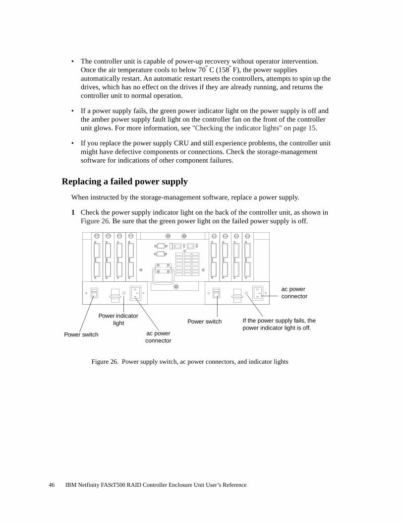
• The controller unit is capable of power-up recovery without operator intervention. Once the air temperature cools to below 70º C (158º F), the power supplies automatically restart. An automatic restart resets the controllers, attempts to spin up the drives, which has no effect on the drives if they are already running, and returns the controller unit to normal operation.
• If a power supply fails, the green power indicator light on the power supply is off and the amber power supply fault light on the controller fan on the front of the controller unit glows. For more information, see "Checking the indicator lights" on page 15.
• If you replace the power supply CRU and still experience problems, the controller unit might have defective components or connections. Check the storage-management software for indications of other component failures.
Replacing a failed power supply
When instructed by the storage-management software, replace a power supply.
1 Check the power supply indicator light on the back of the controller unit, as shown in Figure 26. Be sure that the green power light on the failed power supply is off.
Figure 26. Power supply switch, ac power connectors, and indicator lights
If the power supply fails, the power indicator light is off.
Power switch
ac power connector
ac power connector
Power switch
Power indicator light
46 IBM Netfinity FAStT500 RAID Controller Enclosure Unit User’s Reference
CAUTION:The Power Control button on the device and the power switch on the power supply do not turn off the electrical current supplied to the device. The device also might have more than one power cord. To remove all electrical current from the device, ensure that all power cords are disconnected from the power source
2 Turn off the power switch and unplug the power cord from the failed power supply (see Figure 26 on page 46).
CAUTION:Never remove the cover on a power supply or any part that has the following label attached.
Hazardous voltage, current, and energy levels are present inside any component that has this label attached. There are no serviceable parts inside these components. If you suspect a problem with one of these parts, contact a service technician.
3 Using Figure 27 on page 48 as a guide, remove the failed power supply.
Using the pull handle, lift up and pull out to release the power supply; then, slide it out.
5
1
2
8
Chapter 3. Replacing controller unit components 47

Figure 27. Removing and installing a power supply CRU
Attention: When you handle electrostatic discharge (ESD) sensitive devices, take precautions to avoid damage from static electricity. For details about handling ESD-sensitive devices, refer to the following Web site and use a search term of ESD: http://www.ibm.com/
4 Unpack and install the new power supply, as shown in Figure 27. Using the pull handle, push the power supply into the slot until it locks into place.
5 Plug in the power cord and turn on the power.
6 Check the new power supply and other controller unit indicator lights for faults. For more information, see "Checking the indicator lights" on page 15.
Mini-hubs
The mini-hubs are located on the back of the controller unit (see Figure 28 on page 50). A mini-hub is a single, removable unit that provides the Fibre Channel interface between a controller unit and hosts or drives. The back of the controller unit can accommodate eight mini-hubs: up to four host side and up to four drive side mini-hubs. Each mini-hub has two ports. A Gigabit Interface Converter (GBIC) is installed in a mini-hub port. Then a fiber-optic interface cable is connected into the GBIC. For more information, see "Fibre Channel connections" on page 3 and "GBICs" on page 51.
Pull handle
Power supply
48 IBM Netfinity FAStT500 RAID Controller Enclosure Unit User’s Reference

Servicing notes
Consider the following when servicing mini-hubs:
• You can hot swap (replace) a failed mini-hub while the controller unit is in operation.
• Four indicator lights provide status information. If a mini-hub fails, the interface fault and the bypass indicator lights on the mini-hub glow and the loop good indicator light is off. For more information about indicator lights, see "Checking the indicator lights" on page 15.
• If you replace the mini-hub and the GBICs in them and still experience problems, the controller unit might have defective components or connections. Check the storage-management software for indications of other component failures.
For more information, see "Fibre Channel connections" on page 3 and "Interface ports" on page 5.
Replacing a failed mini-hub
When instructed by the storage-management software, replace a mini-hub. Use this procedure to replace either a failed host-side or drive-side mini-hub.
Attention: To prevent possible data loss, do not pull cables from a mini-hub that has not failed.
1 On the mini-hub that has failed, remove the fiber-optic cables from the GBICs; then, replace the protective caps on the cables.
Note: If you are using IBM GBICs, you must remove the fiber-optic cable from the GBIC before you can remove the GBIC from the mini-hub port.
For proper handling of fiber-optic cables, see "Fibre Channel connections" on page 3.
GBIC
Fiber-opticcable
Chapter 3. Replacing controller unit components 49

2 Remove any GBICs in the mini-hub. If a GBIC you are removing has a metal latch, move the latch to the unlocked (center) position. Pull the GBIC from its mini-hub port; then, replace the protective caps on the GBIC.
3 Loosen the captive screw on the mini-hub; then, grasp the screw and pull the mini-hub from the chassis. Figure 28 shows the location of the mini-hubs and ports.
Figure 28. Removing and installing a mini-hub
Attention: When you handle electrostatic discharge (ESD) sensitive devices, take precautions to avoid damage from static electricity. For details about handling ESD-sensitive devices, refer to the following Web site and use a search term of ESD: http://www.ibm.com/
4 Unpack the new mini-hub and slide it into the appropriate slot; then, tighten the captive screw.
GBIC
Fiber-optic cable
Mini-hub
Mini-hub ports
Captive screw
50 IBM Netfinity FAStT500 RAID Controller Enclosure Unit User’s Reference

5 Replace the GBICs that you removed in Step 2 on page 53.
a Remove the protective cap from the GBIC.
b If the GBIC you are installing has a metal latch, move the metal latch to the unlocked (center) position.
c Slide the GBIC into the mini-hub port.
d Rotate the metal latch outward to the locked position (flush with the rear of the GBIC).
6 Replace the fiber-optic cables that you removed in Step 1 on page 49.
7 Check the indicator lights on the mini-hub.
When the mini-hub is operating properly, the green loop good light is on and the fault light is off. If the mini-hub is connected to a Fibre Channel loop, the amber port bypass light is off. If a problem is indicated, use the storage-management software to check the controller unit status.
GBICs
GBICs (Gigabit Interface Converters) are used to connect mini-hub ports to attached nodes. A GBIC slides into a mini-hub port on the back of the controller unit and then a host- or drive-interface cable connects into the GBIC. For more information, see "Fibre Channel connections" on page 3 and "Mini-hubs" on page 48.
Servicing notes
Consider the following when servicing GBICs:
• You can hot swap (replace) a failed GBIC while the controller unit is in operation.
• The operational loop performance is not affected when you install or remove a GBIC.
• Four indicator lights on a mini-hub provide status information. If a GBIC fails, the interface fault and the bypass indicator lights on the mini-hub glow and the loop good indicator light is off. For more information about indicator lights, see "Checking the indicator lights" on page 15.
• If you replace the GBIC and still experience problems, the controller unit might have defective components or connections. Check the storage-management software for indications of other component failures.
Chapter 3. Replacing controller unit components 51

Replacing a failed GBIC
CAUTION:When laser products (such as CD-ROMs, DVD drives, fiber optic devices, or transmitters) are installed, note the following:
– Do not remove the covers. Removing the covers of the laser product could result in exposure to hazardous laser radiation. There are no serviceable parts inside the device.
– Use of controls or adjustments or performance of procedures other than those specified herein might result in hazardous radiation exposure.
When instructed by the storage-management software, replace a GBIC in the mini-hub.
Attention: To prevent possible data loss, do not pull cables from a GBIC that has not failed.
1 Remove the fiber-optic cable from the GBIC that has failed; then, replace the protective caps on the cables.
Note: If you are using IBM GBICs, you must remove the fiber-optic cable from the GBIC before you can remove the GBIC from the mini-hub port.
DANGER
Some laser products contain an embedded Class 3A or Class 3B laser diode. Note the following.
Laser radiation when open. Do not stare into the beam, do not view directly with optical instruments, and avoid direct exposure to the beam.
52 IBM Netfinity FAStT500 RAID Controller Enclosure Unit User’s Reference

For proper handling of fiber-optic cables, see "Fibre Channel connections" on page 3.
2 Remove the GBICs from the mini-hub ports. If the GBIC you are removing has a metal latch, move the latch to the unlocked (center) position. Pull the failed GBIC from its mini-hub port.
3 Insert the protective cap on the GBIC.
GBIC
Fiber-opticcable
GBIC
Fiber-optic cable
GBIC
Protective cap
Chapter 3. Replacing controller unit components 53

Attention: When you handle electrostatic discharge (ESD) sensitive devices, take precautions to avoid damage from static electricity. For details about handling ESD-sensitive devices, refer to the following Web site and use a search term of ESD: http://www.ibm.com/
4 Unpack the new GBIC; then, do the following:
a Remove the protective cap from the GBIC.
b If the GBIC you are installing has a metal latch, move the metal latch to the unlocked (center) position.
c Slide the GBIC into the mini-hub port.
d Rotate the metal latch outward to the locked position (flush with the rear of the GBIC).
5 Reconnect the interface cables that you removed in Step 1 on page 52.
6 Check the indicator lights on the mini-hub.
When the mini-hub is operating properly, the green loop good light is on and the fault light is off. If the mini-hub is connected to a Fibre Channel loop, the amber port bypass light is off. If a problem is indicated, use the storage-management software to check the controller unit status.
54 IBM Netfinity FAStT500 RAID Controller Enclosure Unit User’s Reference

Appendix. Product warranties and notices
This appendix contains the product warranties, product notices, trademark acknowledgments, electronic emissions statements, and other notices.
Warranty statements
The warranty statements consist of two parts: Part 1 and Part 2. Part 1 varies by country. Part 2 is the same for both statements. Be sure to read both the Part 1 that applies to your country and Part 2.
• United States, Puerto Rico, and Canada (Z125-4753-05 11/97)(Part 1 - General Terms on page 55)
• Worldwide except Canada, Puerto Rico, Turkey, and United States (Z125-5697-01 11/97)(Part 1 - General Terms on page 58)
• Worldwide Country-Unique Terms(Part 2 - Country-Unique Terms on page 60)
IBM Statement of Limited Warranty for United States, Puerto Rico, and Canada (Part 1 - General Terms)
This Statement of Limited Warranty includes Part 1 - General Terms and Part 2 - Country-unique Terms.The terms of Part 2 may replace or modify those of Part 1.The warranties provided by IBM in this Statement of Limited Warranty apply only to Machines you purchase for your use, and not for resale, from IBM or your reseller.The term “Machine” means an IBM machine, its features, conversions, upgrades, elements, or accessories, or any combination of them. The term “Machine” does not include any software programs, whether preloaded with the Machine, installed subsequently or otherwise.Unless IBM specifies otherwise, the following warranties apply only in the country where you acquire the Machine. Nothing in this Statement of Warranty affects any statutory rights of consumers that cannot be waived or limited by contract.If you have any questions, contact IBM or your reseller.
© Copyright IBM Corp. 2000 55

.
The IBM Warranty for MachinesIBM warrants that each Machine 1) is free from defects in materials and workmanship and 2) conforms to IBM’s Official Published Specifications. The warranty period for a Machine is a specified, fixed period commencing on its Date of Installation. The date on your sales receipt is the Date of Installation, unless IBM or your reseller informs you otherwise.
During the warranty period IBM or your reseller, if approved by IBM to provide warranty service, will provide repair and exchange service for the Machine, without charge, under the type of service designated for the Machine and will manage and install engineering changes that apply to the Machine.
If a Machine does not function as warranted during the warranty period, and IBM or your reseller are unable to either 1) make it do so or 2) replace it with one that is at least functionally equivalent, you may return it to your place of purchase and your money will be refunded. The replacement may not be new, but will be in good working order.
Extent of Warranty
The warranty does not cover the repair or exchange of a Machine resulting from misuse, accident, modification, unsuitable physical or operating environment, improper maintenance by you, or failure caused by a product for which IBM is not responsible. The warranty is voided by removal or alteration of Machine or parts identification labels.
THESE WARRANTIES ARE YOUR EXCLUSIVE WARRANTIES AND REPLACE ALL OTHER WARRANTIES OR CONDITIONS, EXPRESS OR IMPLIED, INCLUDING, BUT NOT LIMITED TO, THE IMPLIED WARRANTIES OR CONDITIONS OF MERCHANTABILITY AND FITNESS FOR A PARTICULAR PURPOSE. THESE WARRANTIES GIVE YOU SPECIFIC LEGAL RIGHTS AND YOU MAY ALSO HAVE OTHER RIGHTS WHICH VARY FROM JURISDICTION TO JURISDICTION. SOME JURISDICTIONS DO NOT ALLOW THE EXCLUSION OR LIMITATION OF EXPRESS OR IMPLIED WARRANTIES, SO THE ABOVE EXCLUSION OR LIMITATION MAY NOT APPLY TO YOU. IN THAT EVENT, SUCH WARRANTIES ARE LIMITED IN DURATION TO THE WARRRANTY PERIOD. NO WARRANTIES APPLY AFTER THAT PERIOD.
Items Not Covered by Warranty
IBM does not warrant uninterrupted or error-free operation of a Machine.
Unless specified otherwise, IBM provides non-IBM machines WITHOUT WARRANTIES OF ANY KIND.
Any technical or other support provided for a Machine under warranty, such as assistance via telephone with “how-to” questions and those regarding Machine set-up and installation, will be provided WITHOUT WARRANTIES OF ANY KIND.
Warranty Service
To obtain warranty service for the Machine, contact your reseller or IBM. In the United States, call IBM at 1-800-772-2227. In Canada, call IBM at 1-800-565-3344. You may be required to present proof of purchase.
IBM or your reseller provides certain types of repair and exchange service, either at your location or at a service center, to keep Machines in, or restore them to, conformance with their Specifications. IBM or your reseller will inform you of the available types of service for a Machine based on its country of installation. IBM may repair the failing Machine or exchange it at its discretion.
When warranty service involves the exchange of a Machine or part, the item IBM or your reseller replaces becomes its property and the replacement becomes yours. You represent that all removed items are genuine and unaltered. The replacement may not be new, but will be in good working order and at least functionally equivalent to the item replaced. The replacement assumes the warranty service status of the replaced item.
Machine: IBM Netfinity FAStT500 RAID Controller Enclosure Unit
Warranty Period*: Three Years
*Contact your place of purchase for warranty service information. Some IBM Machines are eligible for On-site warranty service depending on the country where service is performed.
56 IBM Netfinity FAStT500 RAID Controller Enclosure Unit User’s Reference

Any feature, conversion, or upgrade IBM or your reseller services must be installed on a Machine which is 1) for certain Machines, the designated, serial-numbered Machine and 2) at an engineering-change level compatible with the feature, conversion, or upgrade. Many features, conversions, or upgrades involve the removal of parts and their return to IBM. A part that replaces a removed part will assume the warranty service status of the removed part.
Before IBM or your reseller exchanges a Machine or part, you agree to remove all features, parts, options, alterations, and attachments not under warranty service.
You also agree to
1. ensure that the Machine is free of any legal obligations or restrictions that prevent its exchange;
2. obtain authorization from the owner to have IBM or your reseller service a Machine that you do not own; and
3. where applicable, before service is provided
a. follow the problem determination, problem analysis, and service request procedures that IBM or your reseller provides,
b. secure all programs, data, and funds contained in a Machine,
c. provide IBM or your reseller with sufficient, free, and safe access to your facilities to permit them to fulfill their obligations, and
d. inform IBM or your reseller of changes in a Machine’s location.
IBM is responsible for loss of, or damage to, your Machine while it is 1) in IBM’s possession or 2) in transit in those cases where IBM is responsible for the transportation charges.
Neither IBM nor your reseller is responsible for any of your confidential, proprietary, or personal information contained in a Machine which you return to IBM or your reseller for any reason. You should remove all such information from the Machine prior to its return.
Production Status
Each IBM Machine is manufactured from new parts, or new and used parts. In some cases, the Machine may not be new and may have been previously installed. Regardless of the Machine’s production status, IBM’s appropriate warranty terms apply.
Limitation of Liability
Circumstances may arise where, because of a default on IBM’s part or other liability, you are entitled to recover damages from IBM. In each such instance, regardless of the basis on which you are entitled to claim damages from IBM (including fundamental breach, negligence, misrepresentation, or other contract or tort claim), IBM is liable for no more than
1. damages for bodily injury (including death) and damage to real property and tangible personal property; and
2. the amount of any other actual direct damages, up to the greater of U.S. $100,000 (or equivalent in local currency) or the charges (if recurring, 12 months’ charges apply) for the Machine that is the subject of the claim.
This limit also applies to IBM’s suppliers and your reseller. It is the maximum for which IBM, its suppliers, and your reseller are collectively responsible.
UNDER NO CIRCUMSTANCES IS IBM LIABLE FOR ANY OF THE FOLLOWING: 1) THIRD-PARTY CLAIMS AGAINST YOU FOR DAMAGES (OTHER THAN THOSE UNDER THE FIRST ITEM LISTED ABOVE); 2) LOSS OF, OR DAMAGE TO, YOUR RECORDS OR DATA; OR 3) SPECIAL, INCIDENTAL, OR INDIRECT DAMAGES OR FOR ANY ECONOMIC CONSEQUENTIAL DAMAGES (INCLUDING LOST PROFITS OR SAVINGS), EVEN IF IBM, ITS SUPPLIERS OR YOUR RESELLER IS INFORMED OF THEIR POSSIBILITY. SOME JURISDICTIONS DO NOT ALLOW THE EXCLUSION OR LIMITATION OF INCIDENTAL OR CONSEQUENTIAL DAMAGES, SO THE ABOVE LIMITATION OR EXCLUSION MAY NOT APPLY TO YOU.
Appendix. Product warranties and notices 57

IBM Statement of Warranty Worldwide except Canada, Puerto Rico, Turkey, United States (Part 1 - General Terms)
This Statement of Warranty includes Part 1 - General Terms and Part 2 - Country-unique Terms.The terms of Part 2 may replace or modify those of Part 1. The warranties provided by IBM in this Statement of Warranty apply only to Machines you purchase for your use, and not for resale, from IBM or your reseller.The term “Machine” means an IBM machine, its features, conversions, upgrades, elements, or accessories, or any combination of them. The term “Machine” does not include any software programs, whether pre-loaded with the Machine, installed subsequently or otherwise.Unless IBM specifies otherwise, the following warranties apply only in the country where you acquire the Machine.Nothing in this Statement of Warranty affects any statutory rights of consumers that cannot be waived or limited by contract.If you have any questions, contact IBM or your reseller.
The IBM Warranty for MachinesIBM warrants that each Machine 1) is free from defects in materials and workmanship and 2) conforms to IBM’s Official Published Specifications. The warranty period for a Machine is a specified, fixed period commencing on its Date of Installation. The date on your sales receipt is the Date of Installation, unless IBM or your reseller informs you otherwise.
During the warranty period IBM or your reseller, if approved by IBM to provide warranty service, will provide repair and exchange service for the Machine, without charge, under the type of service designated for the Machine and will manage and install engineering changes that apply to the Machine.
If a Machine does not function as warranted during the warranty period, and IBM or your reseller are unable to either 1) make it do so or 2) replace it with one that is at least functionally equivalent, you may return it to your place of purchase and your money will be refunded. The replacement may not be new, but will be in good working order.
Extent of Warranty
The warranty does not cover the repair or exchange of a Machine resulting from misuse, accident, modification, unsuitable physical or operating environment, improper maintenance by you, or failure caused by a product for which IBM is not responsible. The warranty is voided by removal or alteration of Machine or parts identification labels.
THESE WARRANTIES ARE YOUR EXCLUSIVE WARRANTIES AND REPLACE ALL OTHER WARRANTIES OR CONDITIONS, EXPRESS OR IMPLIED, INCLUDING, BUT NOT LIMITED TO, THE IMPLIED WARRANTIES OR CONDITIONS OF MERCHANTABILITY AND FITNESS FOR A PARTICULAR PURPOSE. THESE WARRANTIES GIVE YOU SPECIFIC LEGAL RIGHTS AND YOU MAY ALSO HAVE OTHER RIGHTS WHICH VARY FROM JURISDICTION TO JURISDICTION. SOME JURISDICTIONS DO NOT ALLOW THE EXCLUSION OR LIMITATION OF EXPRESS OR IMPLIED WARRANTIES, SO THE ABOVE EXCLUSION OR LIMITATION MAY NOT APPLY TO YOU. IN THAT EVENT, SUCH WARRANTIES ARE LIMITED IN DURATION TO THE WARRRANTY PERIOD. NO WARRANTIES APPLY AFTER THAT PERIOD.
Items Not Covered by Warranty
IBM does not warrant uninterrupted or error-free operation of a Machine.
Unless specified otherwise, IBM provides non-IBM machines WITHOUT WARRANTIES OF ANY KIND.
Machine: IBM Netfinity FAStT500 RAID Controller Enclosure Unit
Warranty Period*: Three Years
*Contact your place of purchase for warranty service information. Some IBM Machines are eligible for On-site warranty service depending on the country where service is performed.
58 IBM Netfinity FAStT500 RAID Controller Enclosure Unit User’s Reference

Any technical or other support provided for a Machine under warranty, such as assistance via telephone with “how-to” questions and those regarding Machine set-up and installation, will be provided WITHOUT WARRANTIES OF ANY KIND.
Warranty Service
To obtain warranty service for the Machine, contact your reseller or IBM. You may be required to present proof of purchase.
IBM or your reseller provides certain types of repair and exchange service, either at your location or at a service centre, to keep Machines in, or restore them to, conformance with their Specifications. IBM or your reseller will inform you of the available types of service for a Machine based on its country of installation. IBM may repair the failing Machine or exchange it at its discretion.
When warranty service involves the exchange of a Machine or part, the item IBM or your reseller replaces becomes its property and the replacement becomes yours. You represent that all removed items are genuine and unaltered. The replacement may not be new, but will be in good working order and at least functionally equivalent to the item replaced. The replacement assumes the warranty service status of the replaced item.
Any feature, conversion, or upgrade IBM or your reseller services must be installed on a Machine which is 1) for certain Machines, the designated, serial-numbered Machine and 2) at an engineering-change level compatible with the feature, conversion, or upgrade. Many features, conversions, or upgrades involve the removal of parts and their return to IBM. A part that replaces a removed part will assume the warranty service status of the removed part.
Before IBM or your reseller exchanges a Machine or part, you agree to remove all features, parts, options, alterations, and attachments not under warranty service.
You also agree to
1. ensure that the Machine is free of any legal obligations or restrictions that prevent its exchange;
2. obtain authorisation from the owner to have IBM or your reseller service a Machine that you do not own; and
3. where applicable, before service is provided
a. follow the problem determination, problem analysis, and service request procedures that IBM or your reseller provides,
b. secure all programs, data, and funds contained in a Machine,
c. provide IBM or your reseller with sufficient, free, and safe access to your facilities to permit them to fulfil their obligations, and
d. inform IBM or your reseller of changes in a Machine’s location.
IBM is responsible for loss of, or damage to, your Machine while it is 1) in IBM’s possession or 2) in transit in those cases where IBM is responsible for the transportation charges.
Neither IBM nor your reseller is responsible for any of your confidential, proprietary, or personal information contained in a Machine which you return to IBM or your reseller for any reason. You should remove all such information from the Machine prior to its return.
Production Status
Each IBM Machine is manufactured from new parts, or new and used parts. In some cases, the Machine may not be new and may have been previously installed. Regardless of the Machine’s production status, IBM’s appropriate warranty terms apply.
Limitation of Liability
Circumstances may arise where, because of a default on IBM’s part or other liability, you are entitled to recover damages from IBM. In each such instance, regardless of the basis on which you are entitled to claim damages from IBM (including fundamental breach, negligence, misrepresentation, or other contract or tort claim), IBM is liable for no more than
1. damages for bodily injury (including death) and damage to real property and tangible personal property; and
2. the amount of any other actual direct damages, up to the greater of U.S. $100,000 (or equivalent in local currency) or the charges (if recurring, 12 months’ charges apply) for the Machine that is the subject of the claim.
Appendix. Product warranties and notices 59

This limit also applies to IBM’s suppliers and your reseller. It is the maximum for which IBM, its suppliers, and your reseller are collectively responsible.
UNDER NO CIRCUMSTANCES IS IBM LIABLE FOR ANY OF THE FOLLOWING: 1) THIRD-PARTY CLAIMS AGAINST YOU FOR DAMAGES (OTHER THAN THOSE UNDER THE FIRST ITEM LISTED ABOVE); 2) LOSS OF, OR DAMAGE TO, YOUR RECORDS OR DATA; OR 3) SPECIAL, INCIDENTAL, OR INDIRECT DAMAGES OR FOR ANY ECONOMIC CONSEQUENTIAL DAMAGES (INCLUDING LOST PROFITS OR SAVINGS), EVEN IF IBM, ITS SUPPLIERS OR YOUR RESELLER IS INFORMED OF THEIR POSSIBILITY. SOME JURISDICTIONS DO NOT ALLOW THE EXCLUSION OR LIMITATION OF INCIDENTAL OR CONSEQUENTIAL DAMAGES, SO THE ABOVE LIMITATION OR EXCLUSION MAY NOT APPLY TO YOU.
Part 2 - Worldwide Country-Unique Terms
ASIA PACIFIC
AUSTRALIA: The IBM Warranty for Machines: The following paragraph is added to this Section:
The warranties specified in this Section are in addition to any rights you may have under the Trade Practices Act 1974 or other legislation and are only limited to the extent permitted by the applicable legislation.
Extent of Warranty: The following replaces the first and second sentences of this Section:
The warranty does not cover the repair or exchange of a Machine resulting from misuse, accident, modification, unsuitable physical or operating environment, operation in other than the Specified Operating Environment, improper maintenance by you, or failure caused by a product for which IBM is not responsible.
Limitation of Liability: The following is added to this Section:
Where IBM is in breach of a condition or warranty implied by the Trade Practices Act 1974, IBM’s liability is limited to the repair or replacement of the goods or the supply of equivalent goods. Where that condition or warranty relates to right to sell, quiet possession or clear title, or the goods are of a kind ordinarily acquired for personal, domestic or household use or consumption, then none of the limitations in this paragraph apply.
PEOPLE’S REPUBLIC OF CHINA: Governing Law: The following is added to this Statement:
The laws of the State of New York govern this Statement.
INDIA: Limitation of Liability: The following replaces items 1 and 2 of this Section:
1. liability for bodily injury (including death) or damage to real property and tangible personal property will be limited to that caused by IBM’s negligence;
2. as to any other actual damage arising in any situation involving nonperformance by IBM pursuant to, or in any way related to the subject of this Statement of Warranty, IBM’s liability will be limited to the charge paid by you for the individual Machine that is the subject of the claim.
NEW ZEALAND: The IBM Warranty for Machines: The following paragraph is added to this Section:
The warranties specified in this Section are in addition to any rights you may have under the Consumer Guarantees Act 1993 or other legislation which cannot be excluded or limited. The Consumer Guarantees Act 1993 will not apply in respect of any goods which IBM provides, if you require the goods for the purposes of a business as defined in that Act.
Limitation of Liability: The following is added to this Section:
Where Machines are not acquired for the purposes of a business as defined in the Consumer Guarantees Act 1993, the limitations in this Section are subject to the limitations in that Act.
EUROPE, MIDDLE EAST, AFRICA (EMEA)
The following terms apply to all EMEA countries.
60 IBM Netfinity FAStT500 RAID Controller Enclosure Unit User’s Reference

The terms of this Statement of Warranty apply to Machines purchased from an IBM reseller. If you purchased this Machine from IBM, the terms and conditions of the applicable IBM agreement prevail over this warranty statement.
Warranty Service
If you purchased an IBM Machine in Austria, Belgium, Denmark, Estonia, Finland, France, Germany, Greece, Iceland, Ireland, Italy, Latvia, Lithuania, Luxembourg, Netherlands, Norway, Portugal, Spain, Sweden, Switzerland or United Kingdom, you may obtain warranty service for that Machine in any of those countries from either (1) an IBM reseller approved to perform warranty service or (2) from IBM.
If you purchased an IBM Personal Computer Machine in Albania, Armenia, Belarus, Bosnia and Herzegovina, Bulgaria, Croatia, Czech Republic, Georgia, Hungary, Kazakhstan, Kirgihzia, Federal Republic of Yugoslavia, Former Yugoslav Republic of Macedonia (FYROM), Moldova, Poland, Romania, Russia, Slovak Republic, Slovenia, or Ukraine, you may obtain warranty service for that machine in any of those countries from either (1) an IBM reseller approved to perform warranty service or (2) from IBM.
The applicable laws, Country-unique terms and competent court for this Statement are those of the country in which the warranty service is being provided. However, the laws of Austria govern this Statement if the warranty service is provided in Albania, Armenia, Belarus, Bosnia and Herzegovina, Bulgaria Croatia, Czech Republic, Federal Republic of Yugoslavia, Georgia, Hungary, Kazakhstan, Kirghizia, Former Yugoslav Republic of Macedonia (FYROM), Moldova, Poland, Romania, Russia, Slovak Republic, Slovenia, and Ukraine.
The following terms apply to the country specified.
EGYPT: Limitation of Liability: The following replaces item 2 in this Section:
2. as to any other actual direct damages, IBM’s liability will be limited to the total amount you paid for the Machine that is the subject of the claim.
Applicability of suppliers and resellers (unchanged).
FRANCE: Limitation of Liability: The following replaces the second sentence of the first paragraph of this Section:
In such instances, regardless of the basis on which you are entitled to claim damages from IBM, IBM is liable for no more than: (items 1 and 2 unchanged).
GERMANY: The IBM Warranty for Machines: The following replaces the first sentence of the first paragraph of this Section:
The warranty for an IBM Machine covers the functionality of the Machine for its normal use and the Machine’s conformity to its Specifications.
The following paragraphs are added to this Section:
The minimum warranty period for Machines is six months.
In case IBM or your reseller are unable to repair an IBM Machine, you can alternatively ask for a partial refund as far as justified by the reduced value of the unrepaired Machine or ask for a cancellation of the respective agreement for such Machine and get your money refunded.
Extent of Warranty: The second paragraph does not apply.
Warranty Service: The following is added to this Section:
During the warranty period, transportation for delivery of the failing Machine to IBM will be at IBM’s expense.
Production Status: The following paragraph replaces this Section:
Each Machine is newly manufactured. It may incorporate in addition to new parts, re-used parts as well.
Limitation of Liability: The following is added to this Section:
The limitations and exclusions specified in the Statement of Warranty will not apply to damages caused by IBM with fraud or gross negligence and for express warranty.
In item 2, replace “U.S. $100,000” with “1.000.000 DEM.”
Appendix. Product warranties and notices 61

The following sentence is added to the end of the first paragraph of item 2:
IBM’s liability under this item is limited to the violation of essential contractual terms in cases of ordinary negligence.
IRELAND: Extent of Warranty: The following is added to this Section:
Except as expressly provided in these terms and conditions, all statutory conditions, including all warranties implied, but without prejudice to the generality of the foregoing all warranties by the Sale of Goods Act 1893 or the Sale of Goods and Supply of Services Act 1980 are hereby excluded.
Limitation of Liability: The following replaces items one and two of the first paragraph of this Section:
1. death or personal injury or physical damage to your real property solely caused by IBM’s negligence; and 2. the amount of any other actual direct damages, up to the greater of Irish Pounds 75,000 or 125 percent of the charges (if recurring, the 12 months’ charges apply) for the Machine that is the subject of the claim or which otherwise gives rise to the claim.
Applicability of suppliers and resellers (unchanged).
The following paragraph is added at the end of this Section:
IBM’s entire liability and your sole remedy, whether in contract or in tort, in respect of any default shall be limited to damages.
ITALY: Limitation of Liability: The following replaces the second sentence in the first paragraph:
In each such instance unless otherwise provided by mandatory law, IBM is liable for no more than: (item 1 unchanged) 2) as to any other actual damage arising in all situations involving non-performance by IBM pursuant to, or in any way related to the subject matter of this Statement of Warranty, IBM’s liability, will be limited to the total amount you paid for the Machine that is the subject of the claim.
Applicability of suppliers and resellers (unchanged).
The following replaces the second paragraph of this Section:
Unless otherwise provided by mandatory law, IBM and your reseller are not liable for any of the following: (items 1 and 2 unchanged) 3) indirect damages, even if IBM or your reseller is informed of their possibility.
SOUTH AFRICA, NAMIBIA, BOTSWANA, LESOTHO AND SWAZILAND: Limitation of Liability: The following is added to this Section:
IBM’s entire liability to you for actual damages arising in all situations involving nonperformance by IBM in respect of the subject matter of this Statement of Warranty will be limited to the charge paid by you for the individual Machine that is the subject of your claim from IBM.
TURKIYE: Production Status: The following replaces this Section:
IBM fulfils customer orders for IBM Machines as newly manufactured in accordance with IBM’s production standards.
UNITED KINGDOM: Limitation of Liability: The following replaces items 1 and 2 of the first paragraph of this Section:
1. death or personal injury or physical damage to your real property solely caused by IBM’s negligence;
2. the amount of any other actual direct damages or loss, up to the greater of Pounds Sterling 150,000 or 125 percent of the charges (if recurring, the 12 months’ charges apply) for the Machine that is the subject of the claim or which otherwise gives rise to the claim.
The following item is added to this paragraph:
3. breach of IBM’s obligations implied by Section 12 of the Sale of Goods Act 1979 or Section 2 of the Supply of Goods and Services Act 1982.
Applicability of suppliers and resellers (unchanged).
The following is added to the end of this Section:
62 IBM Netfinity FAStT500 RAID Controller Enclosure Unit User’s Reference

IBM’s entire liability and your sole remedy, whether in contract or in tort, in respect of any default will be limited to damages.
NORTH AMERICA
CANADA: Warranty Service: The following is added to this Section:
To obtain warranty service from IBM, call 1-800-565-3344.
UNITED STATES OF AMERICA: Warranty Service: The following is added to this Section:
To obtain warranty service from IBM, call 1-800-772-2227.
Notices
References in this publication to IBM products, programs, or services do not imply that IBM intends to make these available in all countries in which IBM operates. Any reference to an IBM product, program, or service is not intended to state or imply that only that IBM product, program, or service may be used. Subject to IBM’s valid intellectual property or other legally protectable rights, any functionally equivalent product, program, or service may be used instead of the IBM product, program, or service. The evaluation and verification of operation in conjunction with other products, except those expressly designated by IBM, are the responsibility of the user.
IBM may have patents or pending patent applications covering subject matter in this document. The furnishing of this document does not give you any license to these patents. You can send license inquiries, in writing, to:
IBM Director of LicensingIBM CorporationNorth Castle DriveArmonk, NY 10504-1785U.S.A.
Any references in this publication to non-IBM Web sites are provided for convenience only and do not in any manner serve as an endorsement of those Web sites. The materials at those Web sites are not part of the materials for this IBM product and use of those Web sites is at your own risk.
Trademarks
The following terms are trademarks of the IBM Corporation in the United States or other countries or both:
IBMNetfinity
Other company, product, and service names may be trademarks or service marks of others.
Appendix. Product warranties and notices 63

Electronic emissions statements
Federal Communications Commission (FCC) Statement
Note: This equipment has been tested and found to comply with the limits for a Class A digital device, pursuant to Part 15 of the FCC Rules. These limits are designed to provide reasonable protection against harmful interference when the equipment is operated in a commercial environment. This equipment generates, uses, and can radiate radio frequency energy and, if not installed and used in accordance with the instruction manual, may cause harmful interference to radio communications. Operation of this equipment in a residential area is likely to cause harmful interference in which case the user will be required to correct the interference at his own expense.
Properly shielded and grounded cables and connectors must be used in order to meet FCC emission limits. IBM is not responsible for any radio or television interference caused by using other than recommended cables and connectors or by unauthorized changes or modifications to this equipment. Unauthorized changes or modifications could void the user’s authority to operate the equipment.
This device complies with Part 15 of the FCC Rules. Operation is subject to the following two conditions: (1) this device may not cause harmful interference, and (2) this device must accept any interference received, including interference that may cause undesired operation.
Industry Canada Class A emission compliance statement
This Class A digital apparatus complies with Canadian ICES-003.
Avis de conformité à la réglementation d’Industrie Canada
Cet appareil numérique de classe A est conform à la norme NMB-003 du Canada.
United Kingdom telecommunications safety requirements
Notice to Customers
This apparatus is approved under approval number NS/G/1234/J/100003 for indirect connection to public telecommunication systems in the United Kingdom.
European community directive conformance statement
This product is in conformity with the protection requirements of EC Council Directive 89/336/EEC on the approximation of the laws of the Member States relating to electro-magnetic compatibility.
Attention: This is a Class A product. In a domestic environment this product may cause radio interference in which case the user may be required to take adequate measures.
64 IBM Netfinity FAStT500 RAID Controller Enclosure Unit User’s Reference

Australia and New Zealand Class A statement
Attention: This is a Class A product. In a domestic environment this product may cause radio interference in which case the user may be required to take adequate measures.
Taiwanese electromagnetic interference (EMI) statement
Power cords
For your safety, IBM provides a power cord with a grounded attachment plug to use with this IBM product. To avoid electrical shock, always use the power cord and plug with a properly grounded outlet.
IBM power cords used in the United States and Canada are listed by Underwriter’s Laboratories (UL) and certified by the Canadian Standards Association (CSA).
For units intended to be operated at 115 volts: Use a UL-listed and CSA-certified cord set consisting of a minimum 18 AWG, Type SVT or SJT, three-conductor cord, a maximum of 15 feet in length and a parallel blade, grounding-type attachment plug rated 15 amperes, 125 volts.
For units intended to be operated at 230 volts (U.S. use): Use a UL-listed and CSA-certified cord set consisting of a minimum 18 AWG, Type SVT or SJT, three-conductor cord, a maximum of 15 feet in length and a tandem blade, grounding-type attachment plug rated 15 amperes, 250 volts.
For units intended to be operated at 230 volts (outside the U.S.): Use a cord set with a grounding-type attachment plug. The cord set should have the appropriate safety approvals for the country in which the equipment will be installed.
IBM power cords for a specific country are usually available only in that country or region:
Appendix. Product warranties and notices 65

IBM power cord part number
Used in these countries and regions
13F9940 Argentina, Australia, China (PRC), New Zealand, Papua New Guinea, Paraguay, Uruguay, Western Samoa
13F9979 Afghanistan, Algeria, Andorra, Angola, Austria, Belgium, Benin, Bulgaria, Burkina Faso, Burundi, Cameroon, Central African Rep., Chad, Czech Republic, Egypt, Finland, France, French Guiana, Germany, Greece, Guinea, Hungary, Iceland, Indonesia, Iran, Ivory Coast, Jordan, Lebanon, Luxembourg, Macau, Malagasy, Mali, Martinique, Mauritania, Mauritius, Monaco, Morocco, Mozambique, Netherlands, New Caledonia, Niger, Norway, Poland, Portugal, Romania, Senegal, Slovakia, Spain, Sudan, Sweden, Syria, Togo, Tunisia, Turkey, former USSR, Vietnam, former Yugoslavia, Zaire, Zimbabwe
13F9997 Denmark
14F0015 Bangladesh, Burma, Pakistan, South Africa, Sri Lanka
14F0033 Antigua, Bahrain, Brunei, Channel Islands, Cyprus, Dubai, Fiji, Ghana, Hong Kong, India, Iraq, Ireland, Kenya, Kuwait, Malawi, Malaysia, Malta, Nepal, Nigeria, Polynesia, Qatar, Sierra Leone, Singapore, Tanzania, Uganda, United Kingdom, Yemen, Zambia
14F0051 Liechtenstein, Switzerland
14F0069 Chile, Ethiopia, Italy, Libya, Somalia
14F0087 Israel
1838574 Thailand
6252300 Bahamas, Barbados, Bermuda, Bolivia, Brazil, Canada, Cayman Islands, Colombia, Costa Rica, Dominican Republic, Ecuador, El Salvador, Guatemala, Guyana, Haiti, Honduras, Jamaica, Japan, Korea (South), Liberia, Mexico, Netherlands Antilles, Nicaragua, Panama, Peru, Philippines, Saudi Arabia, Suriname, Taiwan, Trinidad (West Indies), United States of America, Venezuela
66 IBM Netfinity FAStT500 RAID Controller Enclosure Unit User’s Reference

Index
Aac power cord locations 12air ventilation around controller unit 39auto-synchronization of firmware on
controller CRUs 30
Bback view of controller unit 2battery
charge indicator 16checking service date 24date of installation 24date of manufacture 24fault indicator lights 16full charge indicator lights 16life expectancy 35maintaining power 35recycling properly 39removing/replacing 35replacement date 24
bezelindicator lights located on 32location 1removing and replacing 11
Ccache memory and battery backup 35cache, installing 256 MB memory 32charging battery 38charging indicator light on battery 16controller CRU
firmware auto-synchronization 30hot swapping 30indicator lights 29redundant pair 30servicing notes 29
controller fanhot swapping 40replacing failed 40servicing notes 40time limit for replacing 40
controller fan fault indicator light 17controller fault indicator light 17controller unit
accessing controls 11adding cache memory 32back view 2front view 1interface ports 7monitoring status through software 14operating tasks table 9overheating 45overtemperature shutdown 22overview 29preparing for move 25proper air ventilation 39shutting down 13, 25temperature overheating in chassis 40turning off power 13turning on power 12
customer replaceable units (CRUs) 1See also individual component names
Ddata, protecting during power outage 35DIMM module installation 32drive enclosures
indicator lightsactivity at powre off 13activity during parity check 13, 25
turning on before controllers 12, 23drive side mini-hub 6
© Copyright IBM Corp. 2000 67
Eelectronic emissions statements 64emergency shutdown 23Ethernet ports 7
Ffailure/fault indicator light
battery 16, 35fan and communications indicator light 19fan and communications module
hot swapping 42overview 42replacing 43servicing notes 42
fast write cache indicator lightchecking before shutdown 13, 25conditions indicated 17
fault indicator lightbattery 16, 18controller CRU 16
fiber-optic cableshandling precautions 4installing in GBICs 5removing protective caps 5
Fibre Channelconnections 3interface ports 7
firmware on controller CRUauto-synchronization 30
front view of controller unit 1full charge battery indicator light 16, 18full charge light on battery 38
GGBICs
described 51hot swapping 51indicator lights on mini-hub 51installing fiber-optic cables 5replacing failed 52servicing notes 51
Gigabit Interface Converter. See GBICs
Hheartbeat indicator light on controller CRU
16
host side mini-hub 6hot swap
controller CRU 30controller fan 40fan and communications module 42GBICs 51mini-hub 48
II/O (input/output), stopping before shutdown
13, 25indicator lights
battery 16, 18bezel 32controller CRU 16controller fan 16, 17fan and communications module 18, 19mini-hub 19, 20overview 15power supply 18, 19, 46
interface portsEthernet 7RS-232 7
Llaser cautions 4, 52life expectancy of battery 24lights, indicator
battery 16, 18bezel 32controller CRU 16controller fan 16, 17drive enclosure activity during parity
check 13, 25fan and communications module 18, 19mini-hub 19, 20overview 15power supply 18, 19, 46
Mmaintenance, battery 35manufacture date, battery 24memory, cache and battery backup 35memory, installing 256 MB cache upgrade 32
68 IBM Netfinity FAStT500 RAID Controller Enclosure Unit User’s Reference
mini-hubdescribed 48drive side 6host side 6hot swapping 48indicator lights 48
bypass (lower port) 20bypass (upper port) 20fault 20icons 20location 19loop good 20
replacing failed 49servicing notes 49
monitoring status of controller unit 14
Nnotices
electronic emissions 64product 55safety information iiitrademarks 63used in this book xvi
Ooperating controller unit
tasks table 9overheating condition
controller unit 39power supply 45
overtemperature condition of controller unit 22
Ppower
battery 35loss and recovery 45turning off 13turning on 12
power cordlocations 12part numbers 65
power indicator lightcontroller CRU 16controller fan 17
power supplyfault indicator lights 46installing/removing 48interchangeable and redundant 45overheating 45overview 45replacing failed 46servicing notes 45
power supply indicator light 17, 19power switch
locations 12turning on and off 12
precautionscontroller fan replacement time limits 40fiber-optic cable 4laser 4, 52
preparing controller unitfor new location 25for shut down 25
publications, related xvi
Rrecovering from emergency shutdown 23redundant pair of controllers 30redundant power supplies 12, 45related publications xviremoving/replacing
battery 35bezel 11controller fan 40fan and communications module 43GBIC 52mini-hub 49power supply 46
replacement date, battery 24RS-232 (serial) ports 7
Ssafety requirements
electrical vfiber-optic cables 4laser cautions vi, 4, 52
serial (RS-232) ports 7service date of battery 24servicing battery 39shutdown sequence for controller unit 13, 25
Index 69

status indicator lights on controller CRU 16status of controller unit, monitoring with
software 14storage-management software
causing controller fan fault in overtemperature condition 22
checking data in cache 35monitoring controller unit status 14
Ttelephone numbers
ordering publications xviitemperature problems
controller unit 39power supply 45
trademarks 63turning off power 13turning on power 12
Vventilation around controller unit 39
Wwarranty statements 55
70 IBM Netfinity FAStT500 RAID Controller Enclosure Unit User’s Reference

®
Part Number: 19K8461
Printed in U.S.A.
April 2000
19K8461