
NetApp Replace Motherboard Tray 215-03669_A0
6
Replacing the Motherboard Tray 1 Replacing the Motherboard Tray This flyer describes how: ◆ “To Remove the Motherboard” on page 1 ◆ “To Install the Replacement Motherboard” on page 4 ◆ “To Complete the Replacement Process” on page 6 You also require the following documentation to perform the identified procedures: ◆ Hardware Overview that is applicable to your system ◆ Data ONTAP® Upgrade Guide or V-Series Upgrade Guide, as and if applicable ◆ Data ONTAP Commands: Manual Page Reference, if applicable ◆ Data ONTAP System Administration Guide, if applicable To Remove the Motherboard This section describes how: ◆ “To Open the System” on page 2 ◆ “To Remove the Components from the Motherboard” on page 2 The following figures shows the location of the components that you must remove before you replace the motherboard. RLM and Risers and PCI Adapter Slots DIMMs DIMMs Thumbscrew CompactFlash Card 215-03669_A0 Copyright © 2008 NetApp, Inc. All rights reserved.
Transcript of NetApp Replace Motherboard Tray 215-03669_A0
Replacing the Motherboard Tray
This flyer describes how:
◆ “To Remove the Motherboard” on page 1
◆ “To Install the Replacement Motherboard” on page 4
◆ “To Complete the Replacement Process” on page 6
You also require the following documentation to perform the identified procedures:
◆ Hardware Overview that is applicable to your system
◆ Data ONTAP® Upgrade Guide or V-Series Upgrade Guide, as and if applicable
◆ Data ONTAP Commands: Manual Page Reference, if applicable
◆ Data ONTAP System Administration Guide, if applicable
To Remove the Motherboard This section describes how:
◆ “To Open the System” on page 2
◆ “To Remove the Components from the Motherboard” on page 2
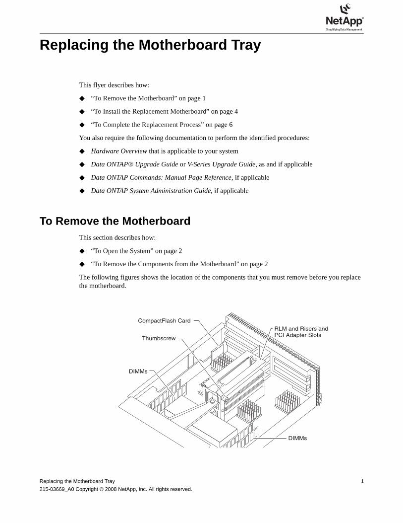
The following figures shows the location of the components that you must remove before you replace the motherboard.
RLM and Risers andPCI Adapter Slots
DIMMs
DIMMs
Thumbscrew
CompactFlash Card
Replacing the Motherboard Tray 1
215-03669_A0 Copyright © 2008 NetApp, Inc. All rights reserved.

To Open the System
1. Ground yourself, shut down the system, unplug the power supplies, remove the cable management tray, and open the system, as described in Hardware Overview, which shipped with your product. If you no longer have that document, you can view it on the NOW™ site at http://now.netapp.com/.
IF your system uses AC power supplies, unplug the power cords from the power source, and then remove the power cords.
IF your system uses DC power supplies, remove the power at the DC source. Remove the DC wires, if necessary.
2. Release the motherboard tray from the system by gently lifting the retaining latch under the motherboard tray, sliding the motherboard tray all the way out of the system, and then placing the motherboard tray on a stable, grounded surface.
To Remove the Components from the Motherboard
You must remove any component, called field-replaceable units (FRUs), from the old motherboard before replacing it. This section describes how:
◆ “To Remove the RLM, PCI Adapters, and Risers” on page 2
◆ “To Remove the DIMMs” on page 4
◆ “To Remove the CompactFlash Card” on page 4
To Remove the RLM, PCI Adapters, and Risers
1. Locate the RLM, in the center of the riser housing, pinch the retaining tabs on the RLM and lift it straight out of the housing, and then set it aside on an antistatic mat.
2. Remove the PCI adapters by completing the following substeps, using the figure as a reference:
RLM
2 To Remove the Motherboard
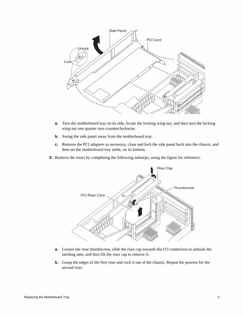
a. Turn the motherboard tray on its side, locate the locking wing nut, and then turn the locking wing nut one quarter turn counterclockwise.
b. Swing the side panel away from the motherboard tray.
c. Remove the PCI adapters as necessary, close and lock the side panel back into the chassis, and then set the motherboard tray aside, on its bottom.
3. Remove the risers by completing the following substeps, using the figure for reference:
a. Loosen the riser thumbscrew, slide the riser cap towards the I/O connectors to unhook the latching tabs, and then lift the riser cap to remove it.
b. Grasp the edges of the first riser and rock it out of the chassis. Repeat the process for the second riser.
Lock
Unlock
PCI Card
Side Panel
Riser Cap
PCI Riser Card
Thumbscrew
Replacing the Motherboard Tray 3

c. Replace the riser cap and slide the top back onto the riser housing. Note that the end tabs should align properly when sliding the top back onto the housing.
d. Secure the top of the riser housing with the thumbscrew.
To Remove the DIMMs
1. Locate the DIMM you want to remove, and then push apart the latches on either side of the DIMM to release the DIMM from its slot.
2. Pull the DIMM straight out of the slot and place it in an antistatic bag.
To Remove the CompactFlash Card
1. Locate the CompactFlash® card on the side of the motherboard tray and gently pull the card straight out of the system. Use the applicable illustration on the back of the motherboard tray as a guide.
2. Set the CompactFlash card aside.
To Install the Replacement Motherboard This section describes how:
◆ “To Reinstall the Components on the Motherboard”
◆ “To Close the System” on page 6
◆ “To Test the System” on page 6
To Reinstall the Components on the Motherboard
You must reinstall the components (FRUs) into the new motherboard tray. This section describes how:
◆ “To Install the CompactFlash Card”
◆ “To Install the DIMMs”
◆ “To Install the Risers, PCI Adapters, and RLM” on page 5
4 To Install the Replacement Motherboard
To Install the CompactFlash Card
1. Turn the motherboard tray so that you can see where the CompactFlash card is inserted.
2. Align the CompactFlash card with the CompactFlash connector inside the system chassis.
IF it is a horizontal installation, insert the CompactFlash card face up.
IF it is a vertical installation, insert the CompactFlash card face in.
3. Seat the CompactFlash card by pushing it firmly into the CompactFlash connector. The CompactFlash card should be squarely seated and should not move. Reseat the CompactFlash card, if necessary.
To Install the DIMMs
1. Locate the DIMM slots on the motherboard. Use the figure in “To Remove the DIMMs” on page 4 for reference.
2. Make sure that you are properly grounded, and then, holding the DIMM by the corners, insert the DIMM straight into the slot.
3. Push carefully, but firmly, on the top edge of the DIMM until the latches snap into place over the notches at the ends of the DIMM. The DIMM fits tightly in the slot, but should go in easily. If not, realign the DIMM with the slot and reinsert it.
4. Repeat Steps 2 and 3 for the remaining DIMMs.
To Install the Risers, PCI Adapters, and RLM
1. Open the riser housing, if necessary. Use the figures in “To Remove the RLM, PCI Adapters, and Risers” on page 2 for reference.
2. Align the first riser with the guide slots on the inside of the riser housing, and then slide the riser all the way down, so that it is seated on top of the adapter socket.
3. Firmly push down on the corners of the riser, fully seating it in the socket.
4. Examine the riser to make sure that it is seated squarely and completely in the socket. The riser must be seated squarely. If it is not, repeat Steps 2 through 4 to reinstall it.
5. Repeat Steps 2 through 4 for the other riser.
6. Reinstall the riser housing cap.
7. Open the system chassis side panels, if necessary, and reinstall the PCI adapters, and then close and lock the side panels. When locking the side panels, push down on the locking wing nut and turn it a quarter turn.
8. Reinstall the RLM.
CautionVisually inspect the DIMM to verify that it is evenly aligned and fully inserted into the slot. The edge connector on the DIMM must make complete contact with the slot.
NoteThere are three sockets where the RLM and risers are installed. The middle socket is reserved for the RLM, while the two outside sockets are reserved for the risers.
Replacing the Motherboard Tray 5

To Close the System
1. Reinstall the motherboard tray and close the system as described in Hardware Overview.
2. Reinstall the cable management tray and recable the system, as needed.
3. Log into NOW site and select the most current version of firmware for your system from those listed at http://now.netapp.com/NOW/download/tools/serviceimage/. Follow the instructions for downloading and installing the new firmware.
NoteInstalling a new motherboard changes the World-Wide Port Name (WWPN) and World-Wide Node Name (WWNN) values associated with each onboard Fibre Channel port. If your configuration uses switched-based zoning, you must adjust the switch zoning to reflect the new WWPN and WWNN values.
To Test the System
After you update the motherboard firmware, you should run diagnostics on the motherboard and motherboard FRUs. If the system passes the diagnostic tests, you can boot the system and bring it back online.
1. Turn on the system and press Ctrl-C to interrupt the boot process.
2. Enter system diagnostics by entering the following command at the prompt:
boot_diags
3. Enter the following command to begin the diagnostics tests on the new motherboard:
run mb
4. Run all motherboard diagnostics by entering 1 from the menu selection.
To Complete the Replacement Process Return the failed part to NetApp®, as described in the RMA instructions shipped with the kit. Contact NetApp technical support at 888-463-8277 (North America), 00-800-44-NETAPP (Europe), or +800-800-80-800 (Asia/Pacific) if you need the RMA number or additional help with the replacement procedure.
NoteYou can run specific motherboard tests by entering the number for the test at the menu prompt. See the Diagnostics Guide for more information.
6 To Complete the Replacement Process