NET1535BU Reference Design for SDDC with NSX and … NSX Network Virtualization Design Guides: NSX...
70
Nimish Desai, Director – NSBU NET1535BU #Vmworld #NET1535BU Reference Design for SDDC with NSX and vSphere: Part 1 VMworld 2017 Content: Not for publication or distribution
Transcript of NET1535BU Reference Design for SDDC with NSX and … NSX Network Virtualization Design Guides: NSX...

Nimish Desai, Director – NSBU
NET1535BU
#Vmworld #NET1535BU
Reference Design for SDDC with NSX and vSphere: Part 1
VMworld 2017 Content: Not fo
r publication or distri
bution
• This presentation may contain product features that are currently under development.
• This overview of new technology represents no commitment from VMware to deliver these features in any generally available product.
• Features are subject to change, and must not be included in contracts, purchase orders, or sales agreements of any kind.
• Technical feasibility and market demand will affect final delivery.
• Pricing and packaging for any new technologies or features discussed or presented have not been determined.
Disclaimer
2
VMworld 2017 Content: Not fo
r publication or distri
bution

Goals of the Session & Customer Takeaway
• Establish reference architecture is validated and proven
• Include existing deployment experience and explain the changes in best practices if any
• Expand session to cover few design topics not covered before – security, routing details etc.
• Include new and upcoming features and changes in design guides
3
VMworld 2017 Content: Not fo
r publication or distri
bution

1 NSX Use Cases
2 NSX Components Connectivity & Design
3 NSX Edge Cluster Design
4 Summary and Q&A
Agenda
4
VMworld 2017 Content: Not fo
r publication or distri
bution

5
SECURITYInherently secure infrastructure
AUTOMATIONApps at the speed of business
APPLICATION CONTINUITYData center anywhere
NSX CUSTOMER USE CASES
Micro-segmentation IT automating IT Disaster recovery
DMZ anywhere Multi-tenant infrastructure Cross cloud
Secure end user Developer cloud Multi data center pooling
VMworld 2017 Content: Not fo
r publication or distri
bution

NSX Architecture and Components
Cloud Consumption • Self Service Portal
• vCloud Automation Center, OpenStack, Custom
Data Plane
ESXiHypervisor Kernel Modules
Distributed Services
• High – Performance Data Plane
• Scale-out Distributed Forwarding Model
Management Plane
NSX Manager
• Single configuration portal
• REST API entry-point
Control Plane• Manages Logical networks
• Control-Plane Protocol
• Separation of Control and Data Plane
Lo
gic
al N
etw
ork
Ph
ys
ica
l
Ne
two
rk
vCenter Server
6
NSX Logical Router Control
VMNSX Controller
NSX Edge
FirewallDistributed
Logical Router
Logical
SwitchVPN
…
…
NSX is AGNOSTIC to Underlay Network Topology
VMworld 2017 Content: Not fo
r publication or distri
bution

1 NSX Use Cases
2 NSX Components Connectivity & Design
3 NSX Edge Cluster Design
4 Summary and Q&A
Agenda
7
VMworld 2017 Content: Not fo
r publication or distri
bution
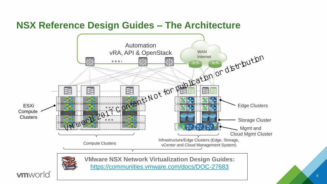
VMware NSX Network Virtualization Design Guides:
https://communities.vmware.com/docs/DOC-27683
NSX Reference Design Guides – The Architecture
Automation
vRA, API & OpenStack
ESXi
Compute
Clusters
Compute ClustersInfrastructure/Edge Clusters (Edge, Storage,
vCenter and Cloud Management System)
Edge Clusters
WAN
Internet
Mgmt and
Cloud Mgmt Cluster
Storage Cluster
8
VMworld 2017 Content: Not fo
r publication or distri
bution

Organizing Compute, Management & Edge
Separation of compute, management and Edge function
with following design advantage
• Managing life-cycle of resources for compute and
Edge functions
• Ability to isolate and develop span of control
• Capacity planning – CPU, Memory & NIC
• Upgrades & migration flexibility
• High availability based on functional need
• Workload specific SLA (DRS & FT)
• Network centric connectivity – P/V, ECMP
• vMotion boundary
• Automation control over area or function that requires
frequent changes
• app-tier, micro-segmentation & load-balancer
Three areas of technology require considerations
• Interaction with physical network
• Overlay (VXLAN) consideration
• Integration with vSphere clustering
Management
WAN
Internet
L3
L2
Compute
Host 1
Host 3
Host 2
Host 6
Host 5
Host 4
Host 1
Host 3
Host 2
Host 6
Host 5
Host 4
Compute
L3
L2
DC Fabric
Edge
NSX
EDGENSX
EDGE
NSX
EDGE
NSX
EDGE
VMworld 2017 Content: Not fo
r publication or distri
bution

Characterization Of Critical Architecture Components
10
ConvergenceAvailability
Rate of Learning
DFW Rule Logic
Availability
API
Bandwidth
Convergence
Availability
Services
Scale
ControllerNSX Manger EDGE
Control Plane
Learning
Convergence
Availability
Control-VM
• Component placement based on design outcome
• Understand management plane & control plane component has different impact then data plane
• Develop metrics and best practices for specific use case
VMworld 2017 Content: Not fo
r publication or distri
bution

▪ NSX Manager deployed as a virtual appliance
• Minimum 16 GB and 4 vCPU
• Larger scale use 24 GB and 8 vCPU
▪ 1:1 relation with vCenter
▪ Availability Considerations – same as any appliance model
• Resiliency of NSX Manager provided by vSphere HA
• Catastrophic failure of NSX Manager is rare, however periodic backup is recommended to restore to the last known configurations
• NSX manger DB schema is specific to version - restore works only with like-to-like version, keep consistence backup
• During the failure all existing data plane connectivity continue to work since data and management plane are separated
▪ NSX Manager also holds DFW rules logic, flow monitoring and local logging data
NSX ManagerDeployment Considerations
11
Management Cluster
WAN
InternetL3
L2
Host 1
Host 3
Host 2
Host 4
VMworld 2017 Content: Not fo
r publication or distri
bution
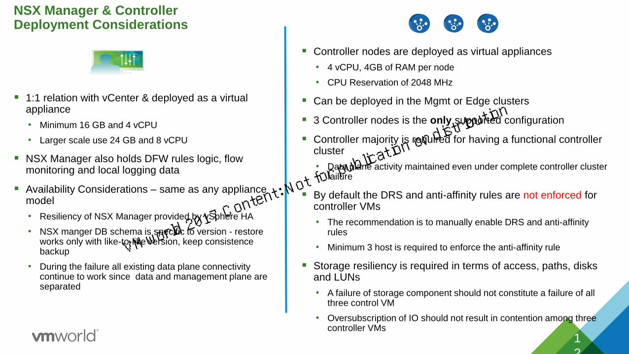
▪ 1:1 relation with vCenter & deployed as a virtual appliance
• Minimum 16 GB and 4 vCPU
• Larger scale use 24 GB and 8 vCPU
▪ NSX Manager also holds DFW rules logic, flow monitoring and local logging data
▪ Availability Considerations – same as any appliance model
• Resiliency of NSX Manager provided by vSphere HA
• NSX manger DB schema is specific to version - restore works only with like-to-like version, keep consistence backup
• During the failure all existing data plane connectivity continue to work since data and management plane are separated
NSX Manager & Controller Deployment Considerations
1
2
▪ Controller nodes are deployed as virtual appliances
• 4 vCPU, 4GB of RAM per node
• CPU Reservation of 2048 MHz
▪ Can be deployed in the Mgmt or Edge clusters
▪ 3 Controller nodes is the only supported configuration
▪ Controller majority is required for having a functional controller cluster
• Data plane activity maintained even under complete controller cluster failure
▪ By default the DRS and anti-affinity rules are not enforced for controller VMs
• The recommendation is to manually enable DRS and anti-affinity rules
• Minimum 3 host is required to enforce the anti-affinity rule
▪ Storage resiliency is required in terms of access, paths, disks and LUNs
• A failure of storage component should not constitute a failure of all three control VM
• Oversubscription of IO should not result in contention among three controller VMs
VMworld 2017 Content: Not fo
r publication or distri
bution

▪ Provide control plane to distribute network information to ESXi hosts
▪ NSX Controllers are clustered for scale out and high availability
▪ Network information is distributed across nodes in a Controller Cluster (slicing)
▪ Remove the VXLAN dependency on multicast routing/PIM in the physical network
▪ Provide suppression of ARP broadcast traffic in VXLAN networks
VXLAN 5000
Logical Router 1
VXLAN 5001
Logical Router 2
VXLAN - 5002
Logical Router 3
Controller VXLAN
Directory Service
MAC table
ARP table
VTEP table
NSX Controllers Functions
VMworld 2017 Content: Not fo
r publication or distri
bution
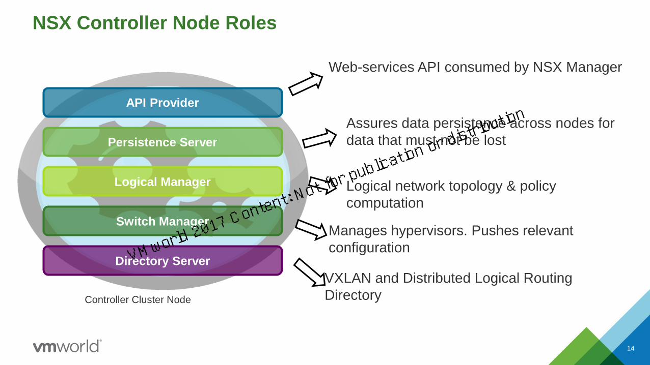
NSX Controller Node Roles
Persistence Server
API Provider
Logical Manager
Switch Manager
Web-services API consumed by NSX Manager
Assures data persistence across nodes for
data that must not be lost
Logical network topology & policy
computation
Manages hypervisors. Pushes relevant
configuration
Controller Cluster Node
Directory Server
VXLAN and Distributed Logical Routing
Directory
14
VMworld 2017 Content: Not fo
r publication or distri
bution
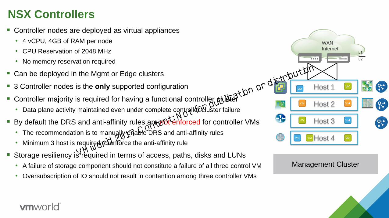
▪ Controller nodes are deployed as virtual appliances
• 4 vCPU, 4GB of RAM per node
• CPU Reservation of 2048 MHz
• No memory reservation required
▪ Can be deployed in the Mgmt or Edge clusters
▪ 3 Controller nodes is the only supported configuration
▪ Controller majority is required for having a functional controller cluster
• Data plane activity maintained even under complete controller cluster failure
▪ By default the DRS and anti-affinity rules are not enforced for controller VMs
• The recommendation is to manually enable DRS and anti-affinity rules
• Minimum 3 host is required to enforce the anti-affinity rule
▪ Storage resiliency is required in terms of access, paths, disks and LUNs
• A failure of storage component should not constitute a failure of all three control VM
• Oversubscription of IO should not result in contention among three controller VMs
NSX Controllers
Management Cluster
WAN
InternetL3
L2
Host 1
Host 3
Host 2
Host 4
VMworld 2017 Content: Not fo
r publication or distri
bution

16
Registration or
Mapping
VM
VM
VM
VM
VM
VM
VM
VM
Compute
A
vCenter Server
NSX Manager NSX
Controller
Compute
B
Edge and Control VM
Single Cluster
Edge ClusterCompute Cluster
▪ Single vCenter Server to manage all Management, Edge and Compute Clusters
• NSX Manager deployed in the Mgmt Cluster and paired to the vCenter Server
• NSX Controllers can also be deployed into the same cluster
• Reduces vCenter Server licensing requirements
Single vCenter Design
VPN VPN
VMworld 2017 Content: Not fo
r publication or distri
bution

17
• Dedicated vCenter Server for managing multiple vCenter domains
• Separate vCenter Server into the Management Cluster to manage the Edge and Compute Clusters
▪ NSX Manager also deployed into the Management Cluster and pared with this second vCenter Server
▪ Can deploy multiple NSX Manager/vCenter Server pairs (separate NSX domains)
• NSX Controllers must be deployed into the same vCenter server where NSX Manager is attached to, therefore the controllers are usually also deployed into the Edge Cluster
Multiple vCenters Design - Multiple NSX Domains
Management VC
Compute
A
Compute
B
Management Cluster
VM
VM
VM
VM
Payload VC for NSX Domain - B
NSX Manager
VM - B
VPN VPN
Edge Cluster
Controller Edge & Control
VM
VM
VM
VM
VM
Payload VC for NSX Domain - A
NSX Manager
VM - A
VPN VPN
Edge Cluster
Controller Edge & Control
VM
Registration or
Mapping
Compute ClustersCompute Clusters
VMworld 2017 Content: Not fo
r publication or distri
bution

Cluster Design with NSX
18
• Flexible DC Design
– Dedicated VC for management cluster
– Dedicated VC that reside in management cluster but manages NSX domain (Edge and Compute)
• Avoid circular dependencies – manager should be always be outside of the infrastructure it manages
• Mobility of mgmt. cluster for remote operations
• Integration with existing VC
• Ability to have more than one NSX-domains with a dedicated VC for mgmt
• Upgrade of VC not affecting – non-NSX domains.
• SRM and other explicit state management is possible
• Simple DC Design
▪ Single VC for managing all components
▪ Separate cluster for compute
▪ Separate Edge & MGMT Cluster
▪ Two VDS that spans VXLAN – compute and Edge
▪ The Edge and MGMT can share the same rack/ToR
VMworld 2017 Content: Not fo
r publication or distri
bution

Transport Zone, VTEP, Logical Networks and VDS ▪ Transport Zone: collection of VXLAN prepared ESXi
clusters
▪ Normally a TZ defines the span of Logical Switches
(Layer 2 communication domains)
▪ VTEP (VXLAN Tunnel EndPoint) is a logical interface
(VMkernel) connects to TZ for encap/decap VXLAN traffic
▪ Multiple TZ is allowed but should not be treated as
security zone
▪ One or more VDS can be part of the same TZ
▪ A given Logical Switch can span multiple VDS
▪ Multiple VDS allows flexibility, connectivity and
operational control
▪ Need to consider L2 vs L3 VTEP Design
▪ IP addressing
▪ Bandwidth and availably considerations VTEP Design
19
vSphere Host
VXLAN Transport
Network
10.20.10.10
Host 1
10.20.10.11
VTEP1 VTEP2
V
M
VXLAN 5002 MAC2
vSphere Host10.20.10.12
Host 2
10.20.10.13
V
M
MAC4
V
MMAC1
V
M
MAC3
VTEP3 VTEP4
vSphere Distributed Switch vSphere Distributed Switch
VMworld 2017 Content: Not fo
r publication or distri
bution

20
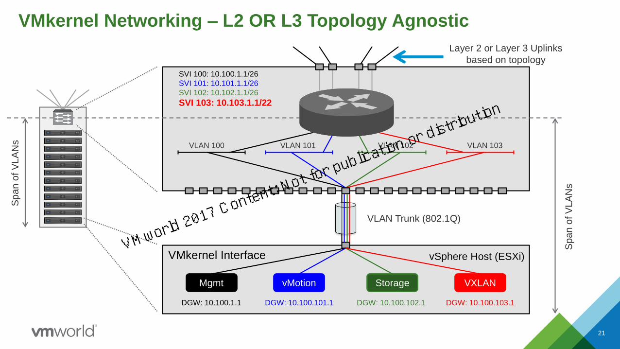
NSX is AGNOSTIC to Underlay Network Topology
L2 or L3 or Any Combination
Only TWO Requirements
IP Connectivity MTU of >1550
https://kb.vmware.com/selfservice/microsites/search.do?lan
guage=en_US&cmd=displayKC&externalId=2093324
vSphere Host (ESXi)
Layer 2 or Layer 3 Uplinks
based on topology
VLAN Trunk (802.1Q)
VLAN 100
Mgmt
DGW: 10.100.1.1
VLAN 101
vMotion
DGW:
10.100.101.1
VLAN 102
Storage
DGW:
10.100.102.1
VLAN 103
VXLAN
DGW:
10.100.103.1
SVI 100: 10.100.1.1/26
SVI 101: 10.101.1.1/26
SVI 102: 10.102.1.1/26
SVI 103: 10.103.1.1/22
Spa
n o
f V
LA
NsSp
an
of V
LA
Ns
VMkernel Interfaces
VMkernel Networking – L2 OR L3 Topology Agnostic
VMworld 2017 Content: Not fo
r publication or distri
bution
VMkernel Networking – L2 OR L3 Topology Agnostic
21
vSphere Host (ESXi)
Layer 2 or Layer 3 Uplinks
based on topology
VLAN Trunk (802.1Q)
VLAN 100
Mgmt
DGW: 10.100.1.1
VLAN 101
vMotion
DGW: 10.100.101.1
VLAN 102
Storage
DGW: 10.100.102.1
VLAN 103
VXLAN
DGW: 10.100.103.1
SVI 100: 10.100.1.1/26
SVI 101: 10.101.1.1/26
SVI 102: 10.102.1.1/26
SVI 103: 10.103.1.1/22
Sp
an
of V
LA
Ns
Sp
an
of V
LA
Ns
VMkernel InterfaceVMworld 2017 Content: N
ot for publicatio
n or distribution

DC Topologies – VLAN ID for VXLAN Must Be the Same
22
VLANs & IP Subnet Defined at each ToR
SVI Interface VLAN ID IP Subnet
Management 100 10.100.R_ID.x/24
vMotion 101 10.101.R_ID.x/24
Storage 102 10.102.R_ID.x/24
VXLAN 103 10.103.R_ID.x/22
VLANs & IP Subnet Defined for POD A
SVI Interface VLAN ID IP Subnet
Management 100 10.100.A.x/24
vMotion 101 10.101.A.x/24
Storage 102 10.102.A.x/24
VXLAN 103 10.103.A.x/22
VLANs & IP Subnet Defined for POD B
SVI Interface VLAN ID IP Subnet
Management 200 10.200.B.x/24
vMotion 201 10.201.B.x/24
Storage 202 10.202.B.x/24
VXLAN 103 10.103.B.x/22
VXLAN VLAN ID 103 - Transport Zone Scope (extends across ALL PODs/clusters)
VLAN ID 100, 101 & 102 Scope VLAN ID 200, 201 and 203 Scope
Compute
Cluster
A
32 Hosts
Compute
Cluster
B
32 Hosts
POD A POD BL3
L2
VLAN ID 100, 101 & 102 Scope VLAN ID 200, 201 and 203 Scope
VXLAN VLAN ID 103 - Transport Zone Scope (extends across ALL PODs/clusters)
Compute
Cluster
A
32 Hosts
Compute
Cluster B
32 Hosts
L3
L2
VMworld 2017 Content: Not fo
r publication or distri
bution

VMkernel Networking – 6.2 Enhancement
▪ TCP/IP Stack for VXLAN – vSphere 5.5
• Introduced with vSphere 5.5 and leveraged by:
VXLAN & NSX vSwitch transport network
▪ Separate routing table, ARP table and default gateway per stack instance
▪ Management, FT, NFS, iSCSI leverage the default TCP/IP stack
▪ VMkernel VLANs do not extend beyond the rack in an L3 fabric design or beyond the
cluster with an L2 fabric, therefore static routes are required for Management and
Storage Traffic
▪ Host Profiles reduce the overhead of managing static routes and ensure persistence
23
▪ TCP/IP Stack for vMotion – vSphere 6.0
• No need for RPQ in for L3 topologies
• Modified TCP stack to improve latency and
speed
VMworld 2017 Content: Not fo
r publication or distri
bution
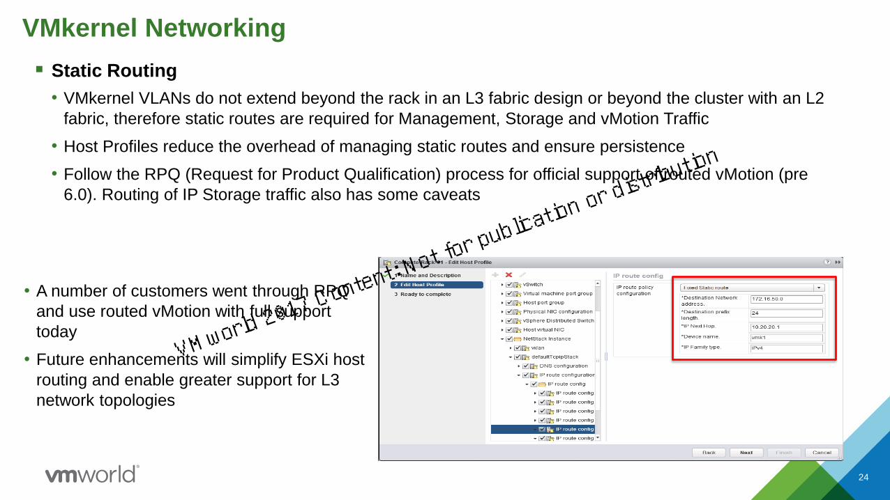
VMkernel Networking
▪ Static Routing
• VMkernel VLANs do not extend beyond the rack in an L3 fabric design or beyond the cluster with an L2
fabric, therefore static routes are required for Management, Storage and vMotion Traffic
• Host Profiles reduce the overhead of managing static routes and ensure persistence
• Follow the RPQ (Request for Product Qualification) process for official support of routed vMotion (pre
6.0). Routing of IP Storage traffic also has some caveats
• A number of customers went through RPQ
and use routed vMotion with full support
today
• Future enhancements will simplify ESXi host
routing and enable greater support for L3
network topologies
24
VMworld 2017 Content: Not fo
r publication or distri
bution

VDS Uplink Design
• NSX create dvUplink port-groups for VXLAN enabled hosts. This
uplink connectivity carrying VXLAN traffic
• Must be consistent for all hosts belonging to the VDS
• For the VXLAN traffic, the choice in teaming mode depends on
• Simplicity
• Bandwidth requirement
• Recommended teaming mode is “Route Based on Originating Port”.
• LACP teaming mode is discouraged:
• LACP teaming mode only allows single VTEP
• LACP teaming forces all the other traffic types to use the same teaming mode
• LACP requires additional configuration and operational consistency
• Having multiple VDS for compute and Edge allow flexibility of teaming more for uplink configuration
• LACP can be used in compute cluster for traffic optimization
25
Teaming and
Failover Mode
NSX
Support
Multi-VTEP
Support
Uplink Behavior
2 x 10G
Route based on
Originating Port
✓ ✓ Both Active
Route based on
Source MAC hash
✓ ✓ Both Active
LACP ✓ × Flow based –both active
Route based on IP
Hash (Static
EtherChannnel)
✓ × Flow based –both active
Explicit Failover Order ✓ × Only one link is active
Route based on
Physical NIC Load
(LBT)
× × ×VMworld 2017 Content: Not fo
r publication or distri
bution
vSphere Host
VXLAN Transport
Network
10.20.10.10
Host 1
10.20.10.11
VTEP1 VTEP2
V
M
VXLAN 5002 MAC2
vSphere Host10.20.10.12
Host 2
10.20.10.13
V
M
MAC4
V
M
MAC1
V
M
MAC3
VTEP3 VTEP4
vSphere Distributed Switch vSphere Distributed Switch
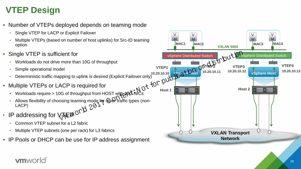
VTEP Design
▪ Number of VTEPs deployed depends on teaming mode
• Single VTEP for LACP or Explicit Failover
• Multiple VTEPs (based on number of host uplinks) for Src-ID teaming option
▪ Single VTEP is sufficient for
• Workloads do not drive more than 10G of throughput
• Simple operational model
• Deterministic traffic mapping to uplink is desired (Explicit Failover only)
▪ Multiple VTEPs or LACP is required for
▪ Workloads require > 10G of throughput from HOST with 10G NICs
• Allows flexibility of choosing teaming mode for other traffic types (non-LACP)
• IP addressing for VTEP
• Common VTEP subnet for a L2 fabric
• Multiple VTEP subnets (one per rack) for L3 fabrics
▪ IP Pools or DHCP can be use for IP address assignment
26
VMworld 2017 Content: Not fo
r publication or distri
bution

NSX for vSphere VXLAN Replication Modes
• Unicast Mode
– All replication occurs using unicast. Applicable to small deployment
• Multicast Mode
– Entire replication is off-loaded to physical network
– Requires IGMP/Querier & and multicast routing for L3(PIM) *
• Hybrid Mode
– Local replication offloaded to physical network, while remote replication occurs via unicast
– Most practical without the complexity of multicast mode
– Only requires IGMP Snooping/Querier. Does not require L3 PIM *
• All modes require an MTU of 1600 bytes.
* Host provides necessary querier function however external querier recommended for manageability/admin-scope
NSX for vSphere provides flexibility for VXLAN Transport – Does not require complex multicast configurations on physical network
27
VMworld 2017 Content: Not fo
r publication or distri
bution
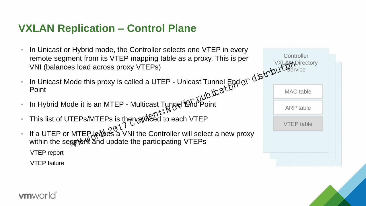
VXLAN Replication – Control Plane
• In Unicast or Hybrid mode, the Controller selects one VTEP in every
remote segment from its VTEP mapping table as a proxy. This is per
VNI (balances load across proxy VTEPs)
• In Unicast Mode this proxy is called a UTEP - Unicast Tunnel End Point
• In Hybrid Mode it is an MTEP - Multicast Tunnel End Point
• This list of UTEPs/MTEPs is then synced to each VTEP
• If a UTEP or MTEP leaves a VNI the Controller will select a new proxy within the segment and update the participating VTEPs
VTEP report
VTEP failure
Controller
VXLAN Directory
Service
MAC table
ARP table
VTEP table
VMworld 2017 Content: Not fo
r publication or distri
bution
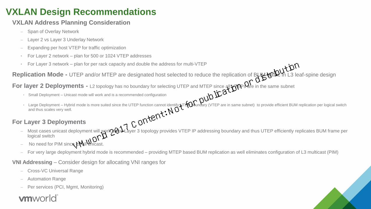
VXLAN Design RecommendationsVXLAN Address Planning Consideration
– Span of Overlay Network
– Layer 2 vs Layer 3 Underlay Network
– Expanding per host VTEP for traffic optimization
• For Layer 2 network – plan for 500 or 1024 VTEP addresses
• For Layer 3 network – plan for per rack capacity and double the address for multi-VTEP
Replication Mode - UTEP and/or MTEP are designated host selected to reduce the replication of BUM traffic in L3 leaf-spine design
For layer 2 Deployments - L2 topology has no boundary for selecting UTEP and MTEP since all VTEPs are in the same subnet
• Small Deployment – Unicast mode will work and is a recommended configuration
• Large Deployment – Hybrid mode is more suited since the UTEP function cannot identify VTEP boundary (VTEP are in same subnet) to provide efficient BUM replication per logical switch
and thus scales very well.
For Layer 3 Deployments
– Most cases unicast deployment will work since Layer 3 topology provides VTEP IP addressing boundary and thus UTEP efficiently replicates BUM frame per logical switch
– No need for PIM since its all unicast.
– For very large deployment hybrid mode is recommended – providing MTEP based BUM replication as well eliminates configuration of L3 multicast (PIM)
VNI Addressing – Consider design for allocating VNI ranges for
– Cross-VC Universal Range
– Automation Range
– Per services (PCI, Mgmt, Monitoring)
VMworld 2017 Content: Not fo
r publication or distri
bution

VXLAN Design Recommendations
Hybrid Mode Functionality and Requirements:
• For the hybrid mode, it is recommended to configure external physical switch with IGMP Querier along with IGMP snooping ( this is an industry standard best practices for most switches including Cisco, Arista, Dell and Brocade).
• If accidentally one forgets to configured IGMP querier in physical switch, as long as IGMP snooping is defined, the hypervisor will send a join to the configured multicast address.
• Hybrid mode is also better when large L2 multicast traffic from VMs requires replication
• It is not recommended to do a replication mode per LS due to enhanced operational complexity.
▪ Beware of multicast reserved address space and avoid using multicast address that will
result into broadcast
▪ http://www.cisco.com/c/dam/en/us/support/docs/ip/ip-multicast/ipmlt_wp.pdf
VMworld 2017 Content: Not fo
r publication or distri
bution

Design Considerations – VDS and Transport ZoneManagement Cluster
Edge Cluster
WebVM
WebVM
VM
VM
WebVM
WebVM
VM
VM
Compute A Compute N
NSX Manager
Controller Cluster NSX Edges
VXLAN Transport Zone Spanning Three Clusters
Compute VDS Edge VDS
VTEP
vSphere Host
vSphere Host
192.168.230.100
192.168.230.101
Compute Cluster 1
vSphere Host
192.168.240.100
Compute Cluster N
vSphere Host
192.168.240.101
vSphere Host
vSphere Host
192.168.220.100
192.168.220.101
VTEP VTEP
Active
VPN
VMworld 2017 Content: Not fo
r publication or distri
bution

1 NSX Use Cases
2 NSX Components Connectivity & Design
3 NSX Edge Cluster Design
4 Summary and Q&A
Agenda
32
VMworld 2017 Content: Not fo
r publication or distri
bution

▪ Resources and components that may be hostsed Edge clusters
• Edge VMs for N-S Traffic
• Control-VM for DLR routing
• Services VM - Load Balancer and VPN
• Optional - Controllers, Monitoring, Log Insight VMs
▪ Type of workload & oversubscriptions desired
• N-S vs. East-West
• Host uplinks, NIC & CPU
▪ Size of DC – Small, Medium & Large
▪ Single vs. multi-VC and DR with SRM
▪ Availability and Scaling
• Limiting VLANs sprawl for peering with ToR
• Rack Availability and BW considerations
• Oversubscription options
33
DC Design ConsiderationEdge Cluster Design
Edge Clusters
Edge Cluster Resource Mapping
WAN
Internet
L3
L2
Compute
Cluster
Host 1
Host 3
Host 2
Host 32
Host y
Host x
VMworld 2017 Content: Not fo
r publication or distri
bution

NSX Edge Gateway: Integrated network services
Firewall
Load Balancing
L2/L3 VPN
Routing/NAT
DHCP/DNS relayDDI
VM VM VM VM VM
• Multi-functional & multi-use VM model. Deployment varies based
on its use, places in the topology, performance etc.
• Functional use – P/V routing only, LB Only, Perimeter FW etc.
• Form factor – X-Large to Compact (one license)
• Stateful switchover of services(FW/NAT, LB, DHCP & IPSEC/SSL)
• Multi-interface routing Support – OSPF & BGP
• Can be deployed in high availability or stand alone mode
• Per tenant Edge services – scaling by interface and instance
• Scaling of north-south bandwidth with ECMP
• Requires design consideration for following
• Edge placement for north-south traffic
• Edge cluster design consideration
• Bandwidth scaling – up to 240 G
• Edge services with multi-tenancy
VMworld 2017 Content: Not fo
r publication or distri
bution

NSX Edge Services Gateway Sizing
35
Edge Services Gateway
Form vCPU Memory MB Specific Usage
X-Large 6 8192Suitable for L7 High Performance LB
VPN Performance
Quad-Large 4 2048Suitable for high performance ECMP
or FW/LB/VPN deployment
Large 2 1024 Small to Medium DC or multi-tenant
Compact 1 512
Small Deployments or single service
use or PoC
• Edge services gateway can be deployed in many sizes depending on services used
• Multiple Edge nodes can be deployed at once e.g. ECMP, LB and Active-Standby for NAT
• When needed the Edge size can be increased or decreased
• In small deployment the Large form is sufficient for many services such as ECMP & LB
• X-Large is required for high performance L7 load balancer configurations
VMworld 2017 Content: Not fo
r publication or distri
bution
36
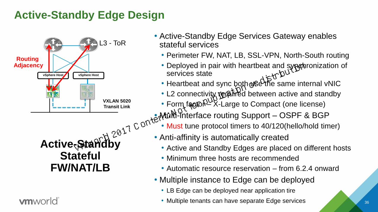
Active-Standby Edge Design
L3 - ToR
Routing Adjacency
vSphere Host vSphere Host
VXLAN 5020
Transit Link
Active-StandbyStateful
FW/NAT/LB
• Active-Standby Edge Services Gateway enables stateful services
• Perimeter FW, NAT, LB, SSL-VPN, North-South routing
• Deployed in pair with heartbeat and synchronization of services state
• Heartbeat and sync both use the same internal vNIC
• L2 connectivity required between active and standby
• Form factor – X-Large to Compact (one license)
• Multi-interface routing Support – OSPF & BGP
• Must tune protocol timers to 40/120(hello/hold timer)
• Anti-affinity is automatically created
• Active and Standby Edges are placed on different hosts
• Minimum three hosts are recommended
• Automatic resource reservation – from 6.2.4 onward
• Multiple instance to Edge can be deployed
• LB Edge can be deployed near application tire
• Multiple tenants can have separate Edge services
VMworld 2017 Content: Not fo
r publication or distri
bution
37
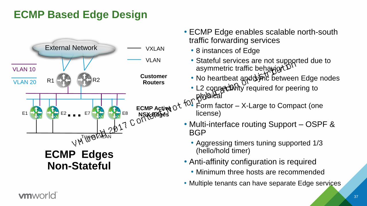
ECMP Based Edge Design
ECMP EdgesNon-Stateful
VXLAN
VLAN
Transit VXLAN
E1 E2 E7 E8
R1 R2
External Network
VLAN 10
VLAN 20
ECMP Active NSX Edges
Customer Routers
…
• ECMP Edge enables scalable north-south traffic forwarding services
• 8 instances of Edge
• Stateful services are not supported due to asymmetric traffic behavior
• No heartbeat and sync between Edge nodes
• L2 connectivity required for peering to physical
• Form factor – X-Large to Compact (one license)
• Multi-interface routing Support – OSPF & BGP
• Aggressing timers tuning supported 1/3 (hello/hold timer)
• Anti-affinity configuration is required
• Minimum three hosts are recommended
• Multiple tenants can have separate Edge services
VMworld 2017 Content: Not fo
r publication or distri
bution

Distributed Logical Routing Components
▪ The Distributed Logical Router Control Plane is
provided by a per instance DLR Control VM and the
NSX Controller
▪ Dynamic Routing Protocols supported with DLR –OSPF and BGP
• Control VM forms the adjacencies with Edge node
▪ Communicates with NSX Manager and Controller Cluster
• NSX Manager sends LIF information to the Control
VM and Controller Cluster
• Control VM sends Routing updates to the Controller Cluster
▪ DLR Control VM and NSX Controller are not in the data path
▪ High availability supported through Active-Standby configuration
▪ Can exist in edge cluster or in compute cluster
Logical Router Control VM
▪ Logical Interfaces (LIFs) on a Distributed Logical Router Instance
• There are internal LIFs and uplink LIFs
• VM Default Gateway traffic is handled by LIFs on the appropriate network
• LIFs are distributed across every hypervisor prepared for NSX
• An ARP table is maintained per LIF
▪ vMAC is the MAC address of an internal LIF
• vMAC is same across all hypervisors and it is never seen by the physical network (only by VMs)
• Routing table on each ESXi hosts is programed via controller
DLR Kernel Module
vSphere
HostLIF1 LIF2
Transit VXLAN
Uplink
VMworld 2017 Content: Not fo
r publication or distri
bution
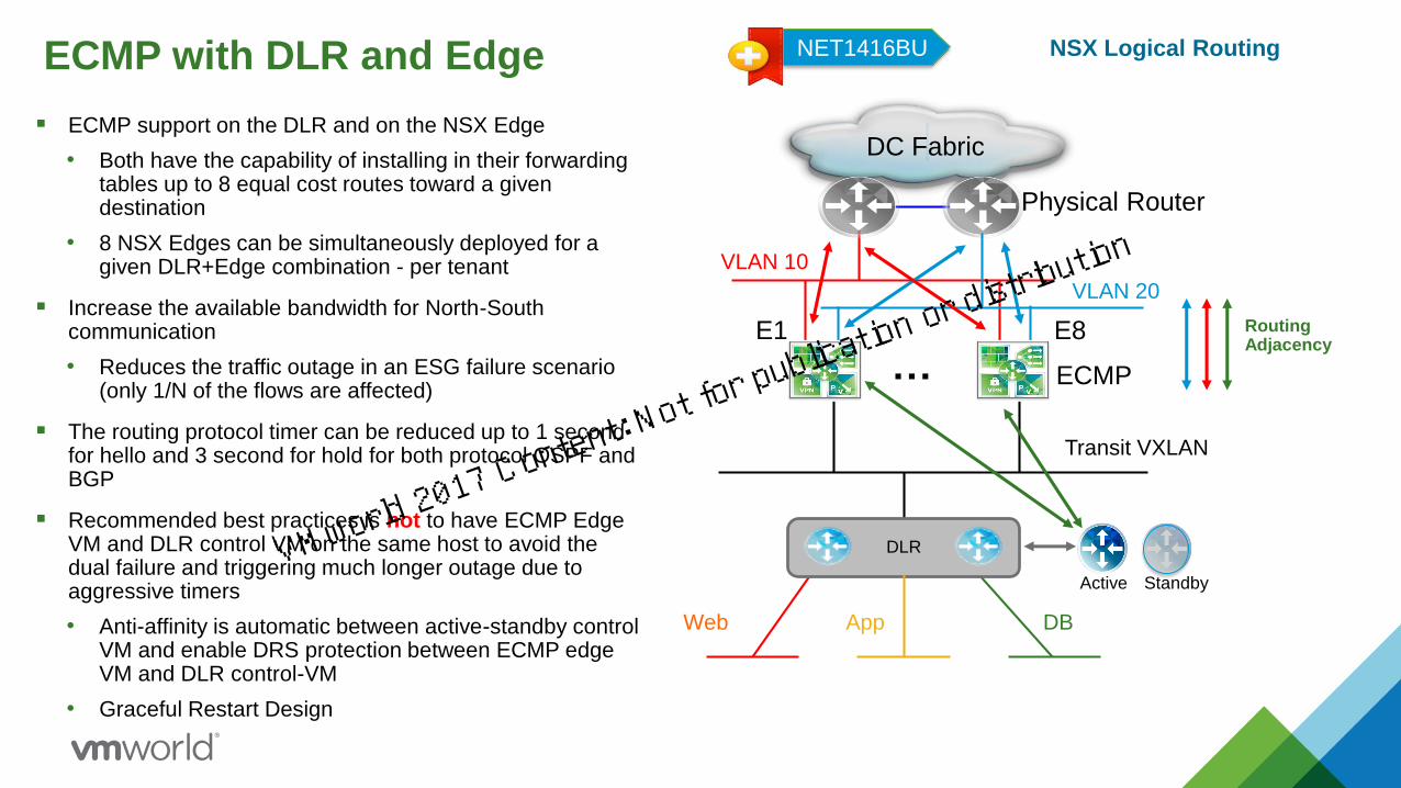
ECMP with DLR and Edge
▪ ECMP support on the DLR and on the NSX Edge
• Both have the capability of installing in their forwarding tables up to 8 equal cost routes toward a given destination
• 8 NSX Edges can be simultaneously deployed for a given DLR+Edge combination - per tenant
▪ Increase the available bandwidth for North-South communication
• Reduces the traffic outage in an ESG failure scenario (only 1/N of the flows are affected)
▪ The routing protocol timer can be reduced up to 1 second for hello and 3 second for hold for both protocol OSPF and BGP
▪ Recommended best practices is not to have ECMP Edge VM and DLR control VM on the same host to avoid the dual failure and triggering much longer outage due to aggressive timers
• Anti-affinity is automatic between active-standby control VM and enable DRS protection between ECMP edge VM and DLR control-VM
• Graceful Restart Design
Web DB
DLR
E1
Physical Router
App
DC Fabric
ECMP
E8
VLAN 20
Transit VXLAN
Active Standby
RoutingAdjacency
…
VLAN 10
NSX Logical RoutingNET1416BU
VMworld 2017 Content: Not fo
r publication or distri
bution

Graceful Restart Design Guidance▪ Graceful Restart (GR) allows the remote node to keep its routing
adjacency alive while the failed node’s control plane undergoing a failure
• Standby node sends a GR message to adjacent neighbor
• The receiving node keep the adjacency alive and continue data plane forwarding to new-actively node
▪ Enabling GR on NSX Edge depends on two factors
• Type of physical router HW support
• Type of Edge configuration – ECMP or Edge-HA
▪ ESG Edge – Stateful Services Mode
• By default its enabled, to avoid secondary failure
• Control-VM GR must also have GR enabled
▪ ECMP Edge
• Disabled GR if the physical router has a single control plane (no dual supervisor)
• The routing protocol timer will expire before GR can kick in. This is the most common case. For physical router with dual-supervisor – the choice depends on what is the probability of failure of physical vs. virtual
• Control-VM GR configuration is irrelevant as adjacency will time out before standby can send GR and does not impact data plane traffic
Web DB
DLR
E1
Physical Router
App
DC Fabric
ECMPOr
ESG
E8
VLAN 20
Transit VXLAN
Active Standby
RoutingAdjacency
…
VLAN 10
NSX Logical RoutingNET1416BU
VMworld 2017 Content: Not fo
r publication or distri
bution

vPC and Routing Peer Termination
Peering over non-VPCParallel LinksUCS FI vPC
Routing Adjacency
Host Host
Uplink TeamingMode
Non-LACP
VXLAN 5020
Transit Link
VXLAN 5020
Transit Link
Routing Adjacency
Host Host
Uplink TeamingMode LACP
Peering over VPCLimited support from Cisco
HW/Release specific Not Recommended
Peering over non-VPCNon-LACP Teaming
Rack Mount
L3
L2
L3
L2
VMworld 2017 Content: Not fo
r publication or distri
bution

NSX Edge Routing Design with Rack-mount server
42
NSX Edge Gateway (all ESGs use same uplink configuration)
VLAN 10 SVI
Router A
VLAN 20 SVI
Router B
VDS-Edge
Uplink A
VLAN 10
dvUplink A
Edge Uplink
Interface 1
connected to
dvPortgroup for
VLAN 10
(vmnic1active
vmnic2 unused)
Uplink B
VLAN20
Edge Uplink
Interface 2
connected to
dvPortgroup for
VLAN 20
(vmnic2 active
vmnic1 unused)
dvUplink B
Default route
from upstream
network is
advertised by
9Ks. Loss of
both uplinks
should withdraw
all routes
eBGP
Peering
▪ 1:1 mapping is created between Edge uplinks (VLAN
backed networks) and routing neighbors on the routers
A/B
▪ Map each of these VLANs (portgroups) to a
different dvUplink on Edge VDS to ensures
distribution of N/S traffic across dvUplinks
▪ The VLANs used for dynamic routing are local to
each router
▪ Edge Uplink = Host Uplink = VLAN = Adjacency
▪ Avoid using LACP to ToR for route peering due to
vendor dependencies
▪ Teaming mode – route based on originating port
▪ Redundancy is handled by Dynamic Routing as Edges
have adjacencies with both routers
▪ eBGP is used between NSX ESG and routers A/B
▪ Equally applicable to OSPF
▪ Default route must follow the uplink status
VMworld 2017 Content: Not fo
r publication or distri
bution

High Availability with Edge Cluster
Edge Active-Standby Guideline
• Minimum three hosts
• Anti-affinity automatic enforced for Edge Active-Standby mode
• Heart beat timers can be reduced from 15 seconds default to 9 seconds
– Internal link for heartbeat for failure detection
• vSphere HA and standby takeover with HB failure routing timer 40/120 Sec.
• Control VM active-standby anti-affinity is automatic
– HB timers for control VM typically do not requires modification
43
ECMP HA Guideline
• Minimum 3 hosts, more if higher BW (VM) is required
• DRS and HA policy governed by how many VMs per host (dependency on BW and uplinks per hosts – 2x10 or 4x10)
• Active Control-VM and Edge VM can not be in same host to avoid dual failure
• Aggressive timers support up to 1/3 sec
• Control VM active-standby anti-affinity is automatic
– HB timers for control VM typically do not requires modification
• In either Edge mode, the vMotion is supported and does not have impact on control plan
VMworld 2017 Content: Not fo
r publication or distri
bution

Edge HA Models Comparison – BW, Services & Convergence
Active/Standby HA Mode
BandwidthSingle Path
(~10-20 Gbps/Tenant)
Stateful Services Supported - NAT, SLB, FW
AvailabilityLow convergence with stateful services
enabled
ECMP Yes with Two Uplinks on Edge HA
ECMP Mode
BandwidthUp to 8 Paths
(~240 Gbps/Tenant)
Stateful Services Not Supported
Availability
High
~ 3-4 sec with (1,3 sec)
timers tuning
E1
Physical Router
Active Standby
E2
Routing Adjacency
Web DB
DLR
AppActive Standby
DLRControl VM
…E8E3E1
Physical Router
E2
Routing Adjacencies
Web DB
DLR
App
Active Standby
DLRControl VMVMworld 2017 Content: N
ot for publicatio
n or distribution

Routing Protocol & Topology
• Enterprise vs. DC Routing
– Core & Aggregation Routing – Handled by backbone team
– DC Spine-Leaf handled by DC Team
– Protocol choices and its connectivity differs in DC
• 10G Links, Convergence is TCP centric – not sub-seconds
• DC Routing Protocol Choices
– Mostly OSPF, BGP is prevalent in large scale design and growing acceptance in enterprise DC fabric
• DC Routing Design and NSX Scope
– NSX domain is connected as Edge routing
• Edge routing features is sufficient for most needs
• Does not act as transport network
– Simplified protocol features and connectivity for NSX
• Use consistent one protocol end-to-end between ESG and physical and DLR to ESG
• Adopting the established routing best practices
– Summarization
– reducing the routing churn as well as protecting black hole of traffic
– Treating NSX as another autonomous system or stub topology
45
OSPF/BGP
L3
L2
WAN/Internet
AS 65501
AS 65002
NSX Routing Domain
DLR
Compute
VMworld 2017 Content: Not fo
r publication or distri
bution

NSX Connectivity with OSPF
• OSPF Protocol Support in NSX
– Support regular as well as NSSA area
• Typically NSSA is a preferred area type
– Supports configurable timers and redistribution
46
Protocol
FeatureEdge HA Edge ECMP
DLR Control-
VM
Area SupportRegular Area &
NSSA
Regular Area &
NSSA
Regular Area &
NSSA
ABR Support Yes Yes NA
RedistributionN2 (if NSSA)
else E2
N2 (if NSSA)
else E2
N2 (if NSSA)
else E2
Hello 10 10 10
Dead 40 40 40
Priority Yes Yes Yes
Cost Yes Yes Yes
Graceful
RestartYes NA Yes
Web DB
DLR
E1
Physical Router
App
DC Fabric
Active
ECMP
E8
VLAN 20
Transit VXLAN
Active Standby
Area 53
NSSA
RoutingAdjacency
…
VLAN 10
Web DB
DLR
E1
Physical Router
App
DC Fabric
Active Standby
E2
Routing Adjacency
External VLAN
Transit VXLAN
Active Standby
Area 53 NSSA
ESG HA
VMworld 2017 Content: Not fo
r publication or distri
bution

NSX Connectivity with OSPF
• N-S Traffic
– Preferred method is to keep ABR at the ToR and peer Edge as a NSSA area router
• The ToR acting as area boarder router - only to send default route to NSX domain
• This allow the summarization of all the logical nets inside NSX to north bound network
– If area 0 cannot be extended to ToR or Area 0 is terminated at aggregation – technical, support and administrative reason
• Edge to peer with ToR as NSSA
• Route summarization at aggregation router
• S-N Traffic
– Redistribute static summary routes towards ABR to avoid control-VM failure with aggressive timers
• Not required in ESG HA model (longer timers)
– In both cases DLR to Edge is also in the same OSPF area as Edge
– DLR control-VM redistribute connected network as E2
47
DLR-1
R1
R2
Area 52
NSSAE1 E2
Control VM
R3
Area 0
REDISTRIBUTE
CONNECTED
REDISTRIBUTE STATIC ROUTE
SUMMARIZING LOGICAL
SWITCH IP ADDRESS SPACE
REDISTRIBUTE STATIC ROUTE
SUMMARIZING LOGICAL
SWITCH IP ADDRESS SPACE
CONVERT LSA 7 INTO LSA 5MAY PROPAGATE SUMMARIZED LOGICAL
SWITCH ADDRESS SPACE ONLY
CONVERT LSA 7 INTO LSA 5MAY PROPAGATE SUMMARIZED LOGICAL
SWITCH ADDRESS SPACE ONLY
ABRINJECT DEFAULT ROUTE
INTO NSSA AREA
ABRINJECT DEFAULT
ROUTE INTO NSSA AREA
Web DBApp
Routing Adjacency
VMworld 2017 Content: Not fo
r publication or distri
bution

NSX Connectivity with BGP
• BGP Protocol Support in NSX
– Support EBGP and iBGP
– Supports configurable timers and redistribution
48Web DB
DLR
E1
Physical Router
App
DC Fabric
Active
ECMP
E8
VLAN 20
Transit VXLAN
Active Standby
AS 65114
RoutingAdjacency
…
VLAN 10
Web DB
DLR
E1
Physical Router
App
DC Fabric
Active Standby
E2
Routing Adjacency
External VLAN
Transit VXLAN
Active Standby
AS 65114
ESG HA
BGP Protocol
FeatureEdge HA Edge ECMP
DLR Control-
VM
EBGP Yes Yes Yes
iBGP Yes Yes Yes
Redistribution Yes Yes Yes
Keepalive 60 60 60
Hold 180 180 180
Multi-Path Yes Yes Yes
Graceful
RestartYes NA Yes
EBGP
iBGP
EBGP
iBGP
VMworld 2017 Content: Not fo
r publication or distri
bution
NSX Connectivity with BGP
49
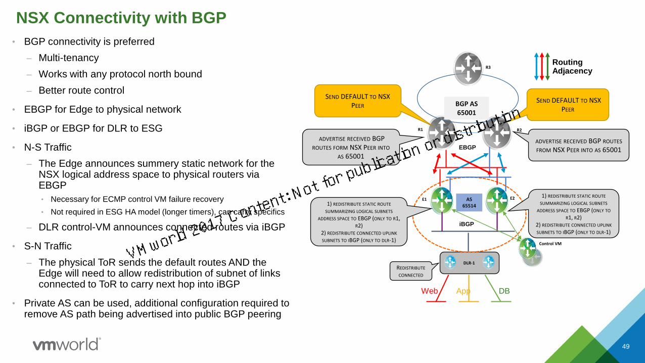
• BGP connectivity is preferred
– Multi-tenancy
– Works with any protocol north bound
– Better route control
• EBGP for Edge to physical network
• iBGP or EBGP for DLR to ESG
• N-S Traffic
– The Edge announces summery static network for the NSX logical address space to physical routers via EBGP
• Necessary for ECMP control VM failure recovery
• Not required in ESG HA model (longer timers), can carry specifics
– DLR control-VM announces connected routes via iBGP
• S-N Traffic
– The physical ToR sends the default routes AND the Edge will need to allow redistribution of subnet of links connected to ToR to carry next hop into iBGP
• Private AS can be used, additional configuration required to remove AS path being advertised into public BGP peering
DLR-1
R1 R2
AS 65514
E1 E2
Control VM
R3
BGP AS 65001
REDISTRIBUTE
CONNECTED
1) REDISTRIBUTE STATIC ROUTE
SUMMARIZING LOGICAL SUBNETS
ADDRESS SPACE TO EBGP (ONLY TO R1, R2)
2) REDISTRIBUTE CONNECTED UPLINK
SUBNETS TO IBGP (ONLY TO DLR-1)
1) REDISTRIBUTE STATIC ROUTE
SUMMARIZING LOGICAL SUBNETS
ADDRESS SPACE TO EBGP (ONLY TO
R1, R2)2) REDISTRIBUTE CONNECTED UPLINK
SUBNETS TO IBGP (ONLY TO DLR-1)
ADVERTISE RECEIVED BGP ROUTES
FROM NSX PEER INTO AS 65001
SEND DEFAULT TO NSX PEER
SEND DEFAULT TO NSX PEER
Web DBApp
Routing Adjacency
EBGP
iBGP
ADVERTISE RECEIVED BGP ROUTES FORM NSX PEER INTO
AS 65001
VMworld 2017 Content: Not fo
r publication or distri
bution
NSX Component Mapping
50
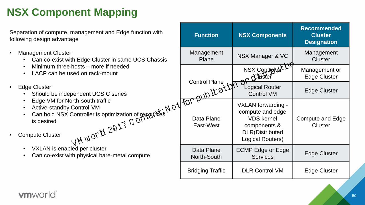
Separation of compute, management and Edge function with
following design advantage
• Management Cluster
• Can co-exist with Edge Cluster in same UCS Chassis
• Minimum three hosts – more if needed
• LACP can be used on rack-mount
• Edge Cluster
• Should be independent UCS C series
• Edge VM for North-south traffic
• Active-standby Control-VM
• Can hold NSX Controller is optimization of resources
is desired
• Compute Cluster
• VXLAN is enabled per cluster
• Can co-exist with physical bare-metal compute
Function NSX Components
Recommended
Cluster
Designation
Management
PlaneNSX Manager & VC
Management
Cluster
Control Plane
NSX Controller
Cluster
Management or
Edge Cluster
Logical Router
Control VMEdge Cluster
Data Plane
East-West
VXLAN forwarding -
compute and edge
VDS kernel
components &
DLR(Distributed
Logical Routers)
Compute and Edge
Cluster
Data Plane
North-South
ECMP Edge or Edge
Services Edge Cluster
Bridging Traffic DLR Control VM Edge Cluster
VMworld 2017 Content: Not fo
r publication or distri
bution
Bridging Design Options
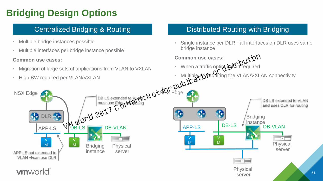
• Multiple bridge instances possible
• Multiple interfaces per bridge instance possible
Common use cases:
• Migration of large sets of applications from VLAN to VXLAN
• High BW required per VLAN/VXLAN
51
NSX Edge
APP-LS
V
M Bridginginstance
Physical server
V
M
DLR
DB-LS DB-VLAN
DB LS extended to VLAN
must use Edge for routing
APP LS not extended to
VLAN can use DLR
Centralized Bridging & Routing
NSX Edge
APP-LS
V
M
V
M
DLR
DB-LS
Bridginginstance
Physical server
DB-VLAN
DB LS extended to VLAN
and uses DLR for routing
Distributed Routing with Bridging
• Single instance per DLR - all interfaces on DLR uses same bridge instance
Common use cases:
• When a traffic optimization required
• Multiple LS requiring the VLAN/VXLAN connectivity
Physical server
VMworld 2017 Content: Not fo
r publication or distri
bution

Web
NSX Edge
App
L3
VM
DB VLAN
VXLAN
VLAN
Combining Overlay to VLAN Routing and Bridging
DB LS
VMVM
The DB tier of our example includes both virtual and physical components: bridging required
• Centralized routing through Edge (HA protected)
• Bridging instance extends logical switch to VLAN:
Bridging instance
52
DLR
VMworld 2017 Content: Not fo
r publication or distri
bution

Web
more Edges…
App
L3
VM
DB VLAN
Combining Overlay to VLAN Routing and Bridging
DB LS
VMVM
NSX Edge
The DB tier of our example includes both virtual and physical components: bridging required
• Centralized routing through Edge (HA protected)
• Bridging instance extends logical switch to VLAN:
• Scale out still possible for other L3 traffic
VXLAN
VLAN
Bridging instance
53
DLR
VMworld 2017 Content: Not fo
r publication or distri
bution
Web
more Edges…
App
L3
V
M
DB VLAN
Combining Overlay to VLAN Routing and Bridging (6.2)
DB LSV
MV
M
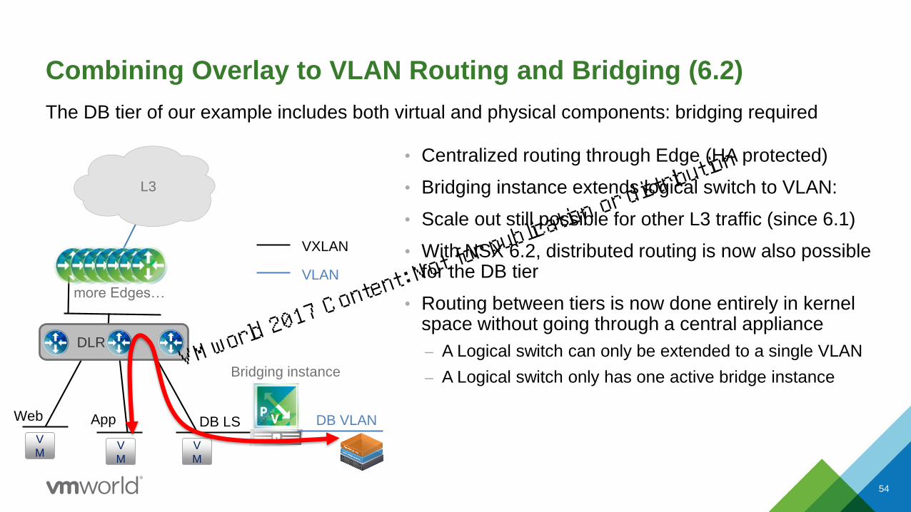
The DB tier of our example includes both virtual and physical components: bridging required
• Centralized routing through Edge (HA protected)
• Bridging instance extends logical switch to VLAN:
• Scale out still possible for other L3 traffic (since 6.1)
• With NSX 6.2, distributed routing is now also possible for the DB tier
• Routing between tiers is now done entirely in kernel space without going through a central appliance
– A Logical switch can only be extended to a single VLAN
– A Logical switch only has one active bridge instance
VXLAN
VLAN
Bridging instance
54
DLR
VMworld 2017 Content: Not fo
r publication or distri
bution
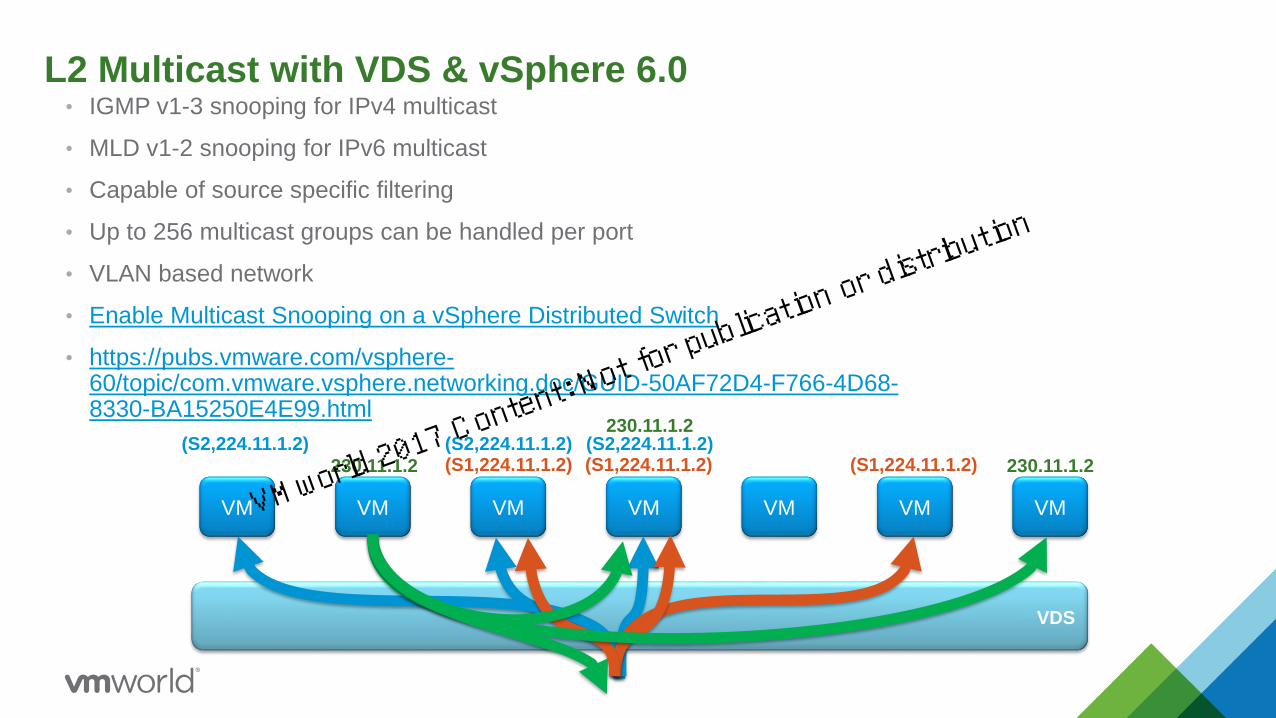
L2 Multicast with VDS & vSphere 6.0• IGMP v1-3 snooping for IPv4 multicast
• MLD v1-2 snooping for IPv6 multicast
• Capable of source specific filtering
• Up to 256 multicast groups can be handled per port
• VLAN based network
• Enable Multicast Snooping on a vSphere Distributed Switch
• https://pubs.vmware.com/vsphere-60/topic/com.vmware.vsphere.networking.doc/GUID-50AF72D4-F766-4D68-8330-BA15250E4E99.html
VDS
VM VM VM VM VM VM VM
(S1,224.11.1.2) (S1,224.11.1.2)(S1,224.11.1.2)(S2,224.11.1.2) (S2,224.11.1.2)(S2,224.11.1.2)
230.11.1.2
230.11.1.2
230.11.1.2
VMworld 2017 Content: Not fo
r publication or distri
bution
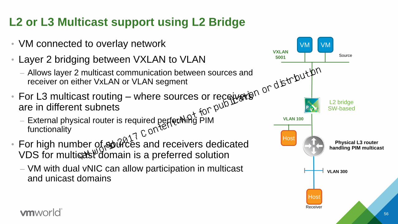
L2 or L3 Multicast support using L2 Bridge
• VM connected to overlay network
• Layer 2 bridging between VXLAN to VLAN
– Allows layer 2 multicast communication between sources and receiver on either VxLAN or VLAN segment
• For L3 multicast routing – where sources or receivers are in different subnets
– External physical router is required performing PIM functionality
• For high number of sources and receivers dedicated VDS for multicast domain is a preferred solution
– VM with dual vNIC can allow participation in multicast and unicast domains
56
L2 bridgeSW-based
VLAN 100
Physical L3 routerhandling PIM multicast
VXLAN
5001 Source
Host
Receiver
VLAN 300
Host
VM VM
VMworld 2017 Content: Not fo
r publication or distri
bution

▪ Edge Cluster design and capacity planning depends
on many factors
▪ Components in Edge clusters
• Edge VMs for N-S Traffic
• Control-VM for DLR routing
• Services VM - Load Balancer and VPN
• Optional - Controllers, Monitoring, Log Insight VMs
▪ Type of workload & oversubscriptions desired
• N-S vs. East-West
• Host uplinks, NIC & CPU
▪ Single vs. multi-VC and DR with SRM
▪ Availability and Scaling
• Limiting VLANs sprawl for peering with ToR
• HA, DRS, BW and Rack Availability
▪ Size of DC – Small, Medium & Large
57
Edge Cluster Design
Should I mix clusters?
Cluster Design Choices and
Components Sizing
WAN
InternetL3
L2
Host 1
Host 3
Host 2
Host z
Host y
Host x
What type of Edge mode is right?
Where would I put control VM?
How do I scale?
Growth & advance functions?
What is the minimum configuration?
VMworld 2017 Content: Not fo
r publication or distri
bution

NSX sizing is based on a modular footprint
• NSX footprint is sized based on customer requirements then map NSX components to infrastructure resources
• Similarly separate VCs for Management and Compute is not an NSX requirement
58
• Flexibility with NSX components
– Controller are in management cluster with single VC
– Controller must register to VC where NSX manager resides
– Edge Resources are flexible in terms of vCPU and memory
– NSX stack is flexible – DFW only vs. full stack
– Three tier licensing allow flexibility that maps to cost and growth
– Understanding the workload that impact NSX component selection
– Edge workload is CPU centric with consistent memory – except in L7 load-balancer Edge services
– Edge resources requires external connectivity to VLANs thus restricting it location to avoid VLAN sprawl
VMworld 2017 Content: Not fo
r publication or distri
bution
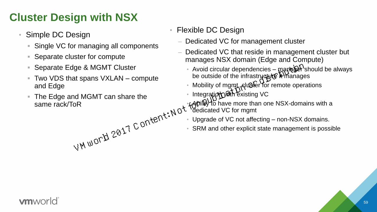
Cluster Design with NSX
59
• Flexible DC Design
– Dedicated VC for management cluster
– Dedicated VC that reside in management cluster but manages NSX domain (Edge and Compute)
• Avoid circular dependencies – manager should be always be outside of the infrastructure it manages
• Mobility of mgmt. cluster for remote operations
• Integration with existing VC
• Ability to have more than one NSX-domains with a dedicated VC for mgmt
• Upgrade of VC not affecting – non-NSX domains.
• SRM and other explicit state management is possible
• Simple DC Design
▪ Single VC for managing all components
▪ Separate cluster for compute
▪ Separate Edge & MGMT Cluster
▪ Two VDS that spans VXLAN – compute and Edge
▪ The Edge and MGMT can share the same rack/ToR
VMworld 2017 Content: Not fo
r publication or distri
bution

Small Design Considerations
• Single cluster for small design, expand to medium with separation of compute cluster
– Single cluster can start with DFW only design
• NSX Manager is the only component required
• VDS license comes with NSX
– Centralize Edge without DLR allows one or two rack deployment
• Static routing for simplicity and reduced need of deploying control-VM
– Progress to full stack for other services such as FW, LB, VPN and VxLAN
• ESG in active-standby – Large form factor
• Quad-large if needed for firewall throughput
60
Single Cluster with NSX
WAN
Internet
L3
L2
Host 1
Host 3
Host 2
Host 32
Host y
Host x
NSX in Small Data Centers for Small and
Medium Businesses NET1345BU
VMworld 2017 Content: Not fo
r publication or distri
bution

Cluster Design with Medium DC
61
• Mixing compute and edge workload requires
– Balanced Compute workload can be mixed with Edge VM resources
– However the growth of compute can put additional burden on managing resource reservation to protect the Edge VM CPU
• Collapsing edge OR compute with management components (VC and NSX manager)
– Requires management component to be dependent on VXLAN since VXLAN enablement is per cluster bases
– Expansion or decoupling of management required for growth
• moving management cluster to remote location
• Having multiple VCs to manage separation
• Mixing Edge and Management is a better strategy
– Consistent static requirements of the resources – mgmt. is relatively time idle resources compared to compute workload
• For growth consider separation of edge and mgmt. cluster
Management
&
Edge Clusters
Separate Compute
Common Edge and Management Cluster
with NSX
WAN
Internet
L3
L2
Compute
Cluster
Host 1
Host 3
Host 2
Host 32
Host y
Host x
VMworld 2017 Content: Not fo
r publication or distri
bution

Cluster Design with Medium DC - Continue
62
• Small to medium design can utilize the edge service gateway features where
– N-S BW is not more then 10 G
– Desire to reduce external FW usage with Edge FW functionality
– Using built in Load Balancer
– Use VPN or SSL functionality
• Edge Services Sizing
– Start with Large (2 vCPU) if the line rate BW is not required
– Can be upgraded to Quad-Large (4 vCPU) for growth in BW
• Consider LB in single arm mode to be near the application segments
• Decouple the need to Edge service mode choice if only LB service is required
Management
&
Edge Clusters
Separate Compute
Common Edge and Management Cluster
with NSX
WAN
Internet
L3
L2
Compute
Cluster
Host 1
Host 3
Host 2
Host 32
Host y
Host x
VMworld 2017 Content: Not fo
r publication or distri
bution

Resiliency Considerations
• vSphere provides tools and options to protect virtual deployment (vSphere license dependent)
• vSphere HA (Enterprise Lic.)
– “Host Monitoring” and “VM Monitoring”
– Redundant management connections
– Datastore heart-beating
• vMotion (Standard Lic.)
• DRS (Distributed Resource Scheduler) (Enterprise Lic.)
• Resource Pool (Enterprise Lic.)
• Individual VM Resource Reservation (All Lic.)
– Use when resource constrained
• VM Boot Order (All Lic.)
• NIC Teaming / NIOC 3 (VDS free with NSX)
• Controller deployed in Cluster
• ESG and DLR Control VM in Active/Standby HA mode
• ESG in ECMP mode
• NSX Manager backup
• Firewall config. Export/Import
Using vSphere Using NSX
VMworld 2017 Content: Not fo
r publication or distri
bution
1 NSX Use Cases
2 NSX Components Connectivity & Design
3 NSX Edge Cluster Design
4 Summary and Q&A
Agenda
64
VMworld 2017 Content: Not fo
r publication or distri
bution
Reference Designs
VMworld 2017 Content: Not fo
r publication or distri
bution

66
NSX
Reference
Designs
NSX
Platform
Hardening
NSX
Getting
Started
Guides
SDDC
Validated
Solutions
NSX
Partner
White
papers
Reference Designs & Technical Papers on VMware Communities:
https://communities.vmware.com/docs
Reference Designs and Technical Papers on the NSX Portal:
http://www.vmware.com/products/nsx/resources.html
NSX and
Fabric
Vendors
VMware NSX Collateral Landscape
VMworld 2017 Content: Not fo
r publication or distri
bution

VMware NSX Network Virtualization Design Guides:
https://communities.vmware.com/docs/DOC-27683
NSX Reference Design Guides – The Architecture
ESXi
Compute
Clusters
Compute ClustersInfrastructure/Edge Clusters (Edge, Storage,
vCenter and Cloud Management System)
Edge Clusters
WAN
Internet
Mgmt and
Cloud Mgmt Cluster
Storage Cluster
67
VMworld 2017 Content: Not fo
r publication or distri
bution

68
Join VMUG for exclusive access to NSX
vmug.com/VMUG-Join/VMUG-Advantage
Connect with your peers
communities.vmware.com
Find NSX Resources
vmware.com/products/nsx
Network Virtualization Blog
blogs.vmware.com/networkvirtualization
WHERE TO GET STARTED
Dozens of Unique NSX Sessions
Spotlights, breakouts, quick talks & group discussions
Visit the VMware Booth
Product overview, use-case demos
Visit Technical Partner Booths
Integration demos – Infrastructure, security, operations,
visibility, and more
Meet the Experts
Join our Experts in an intimate roundtable discussion
Free Hands-on Labs
Test drive NSX yourself with expert-led or self-paces
hands-on labs
labs.hol.vmware.com
Training and Certification
Several paths to professional certifications. Learn
more at the Education & Certification Lounge.
vmware.com/go/nsxtraining
Engage and Learn Experience
Try TakeVMworld 2017 Content: N
ot for publicatio
n or distribution
VMworld 2017 Content: Not fo
r publication or distri
bution

VMworld 2017 Content: Not fo
r publication or distri
bution