INFN Tier1 Status report Spring HEPiX 2005 Andrea Chierici – INFN CNAF.
LABORATORI NAZIONALI DI FRASCATI
SIS – Pubblicazioni
LNF–08/ 25 (IR) November 11, 2008
NERONE TEST AT 2500 m DEPTH
Marco Cordelli, Roberto Habel, Agnese Martini, Luciano Trasatti INFN-Laboratori Nazionali di Frascati Via E. Fermi 40, I-00044 Frascati, Italy
Abstract
NERONE is an instrument designed and built at the LNF to measure with high accuracy and without any bias the attenuation length of light in clean water, capable of operation up to 4000m m depth. Several new technical solutions have been used in the design, including a small and cheap stepper motor assembly. In september 2008, final tests were conducted to a depth of 2500 m, and the results show that the instrument is performing according to design. PACS.: 06.70.Dn

— 2 —
1 INTRODUCTION The attenuation length of light in water is one of the most important parameters for the
design of a deep seawater telescope for neutrino astronomy. It determines the distance between PM tubes which detect the Čerenkov light generated by the µ mesons produced by high energy neutrinos. Commercial instruments are available for this measurement, and have been extensively used by the group [1] for site characterization. Unfortunately they are designed to measure rather dirty waters, and for extremely clear waters, like at the bottom of the Mediterranean sea, they suffer from the need of a reference to absolutely pure water. Their measurements are only relative.
After preliminary tests with a manual system, NERO [2], we have designed and built NERONE, an instrument capable of measuring without the need for external calibration, by the simple method of measuring the attenuation of light over different lengths of water, up to 3 meters, moving a mirror by means of a small motor.
Fig. 1: NERONE in the laboratory and during deployment.
While this method is theoretically very simple, when applied to an instrument which has to work at 3000 m under sea level it creates a number of technical problems. Small motors for deep underwater use are not readily available commercially, and the same is true for long straight rails resistant to seawater. Moreover, a beam with acceptable dimensions from 12 cm to 3 m is difficult to build and to control. NERONE has been tested during five cruises: on 6/11/2001 on the ship Thetis we performed
— 3 —
the first tests at low depth [3], on 16/8/2002 we deployed it to 3100 m on the ship Alliance, on 20/7/2003 and 12/2/2004 on the ship Thetis we solved all movement and alignment problems, and on 1/6/2006 on the ship Universitatis we obtained the first acceptable results, but only at the Catania test site at a depth of 2000 m [4]. In september 2008, during a cruise on the URANIA oceanographic ship owned by CNR, final tests were conducted to a depth of 2500 m, and very good results were obtained. Fig. 1 shows NERONE in the laboratory and during deployment. 2 NERONE
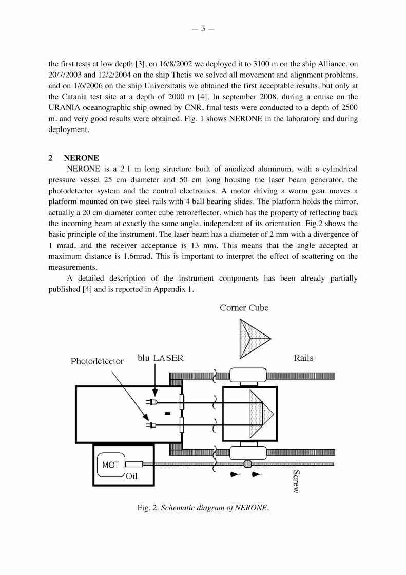
NERONE is a 2.1 m long structure built of anodized aluminum, with a cylindrical pressure vessel 25 cm diameter and 50 cm long housing the laser beam generator, the photodetector system and the control electronics. A motor driving a worm gear moves a platform mounted on two steel rails with 4 ball bearing slides. The platform holds the mirror, actually a 20 cm diameter corner cube retroreflector, which has the property of reflecting back the incoming beam at exactly the same angle, independent of its orientation. Fig.2 shows the basic principle of the instrument. The laser beam has a diameter of 2 mm with a divergence of 1 mrad, and the receiver acceptance is 13 mm. This means that the angle accepted at maximum distance is 1.6mrad. This is important to interpret the effect of scattering on the measurements.
A detailed description of the instrument components has been already partially published [4] and is reported in Appendix 1.
Fig. 2: Schematic diagram of NERONE.
— 4 —
3 THE MEASUREMENTS The measurement campaign took place at the nk16 location south of the sicilian coast,
in September 2008. The site coordinates, measured by GPS, were 36°46.98’ N and 15°27.00’ E during the
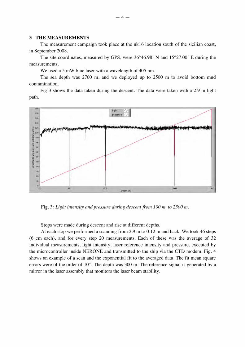
measurements. We used a 5 mW blue laser with a wavelength of 405 nm. The sea depth was 2700 m, and we deployed up to 2500 m to avoid bottom mud
contamination. Fig 3 shows the data taken during the descent. The data were taken with a 2.9 m light
path.
Fig. 3: Light intensity and pressure during descent from 100 m to 2500 m. Stops were made during descent and rise at different depths. At each stop we performed a scanning from 2.9 m to 0.12 m and back. We took 46 steps
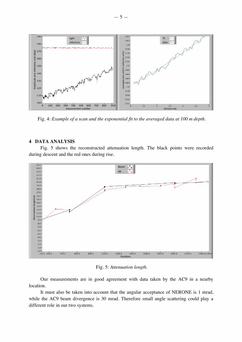
(6 cm each), and for every step 20 measurements. Each of these was the average of 32 individual measurements, light intensity, laser reference intensity and pressure, executed by the microcontroller inside NERONE and transmitted to the ship via the CTD modem. Fig. 4 shows an example of a scan and the exponential fit to the averaged data. The fit mean square errors were of the order of 10-5. The depth was 300 m. The reference signal is generated by a mirror in the laser assembly that monitors the laser beam stability.
— 5 —
Fig. 4: Example of a scan and the exponential fit to the averaged data at 100 m depth. 4 DATA ANALYSIS
Fig. 5 shows the reconstructed attenuation length. The black points were recorded during descent and the red ones during rise.
Fig. 5: Attenuation length. Our measurements are in good agreement with data taken by the AC9 in a nearby
location. It must also be taken into account that the angular acceptance of NERONE is 1 mrad,
while the AC9 beam divergence is 30 mrad. Therefore small angle scattering could play a different role in our two systems.
— 6 —
We want to stress that NERONE, with suitable modifications, could be used to measure small angle scattering, if it is ascertained that this measurement is relevant to the design of the kilometer cube detector.
We also have a method for checking that our instrument is behaving correctly. If a measurement is taken in air, the attenuation length should be infinite. We checked this by performing measurements on the deck of the ship before and after deployment
Before deployment the attenuation length was 950 m. Immediately after recovery we measured 80 m, but after cleaning the windows the final
result was 337 m. Although these results include a large error, they show that our system is stable and not influenced by the drop process.
We must here stress a point. When the instrument is lowered into the water, it has to go through the dirty superficial layers of the sea before reaching the interesting range. Therefore not only NERONE, but also any other instrument suffers from the dirt deposited on the windows, that we attribute mostly to surface oil.
5 THE FUTURE We need further tests and measurements, and to be able to make drops at the KM4 site
down to 3000 m, possibly taking measurements together with the AC-9. We are also planning several improvements for NERONE. First of all we want to be independent of the CTD. Therefore we implemented the
pressure sensor on our instrument. We will also put a Lead-acid battery inside the pressure vessel, to get rid of the battery pack. This kind of battery will give us longer autonomy, and a lighter assembly.
Moreover, we will substitute our large corner cube with 3 small ones, one on the moving platform and two placed between the windows of the laser and the detector. This will effectively double the measuring range with consequent refinement of the measurements or, alternatively, reduction of the overall length of the instrument.
Finally, we want to redesign NERONE to make it resistant to seawater corrosion, to be able to install it permanently in underwater experiments.
— 7 —
APPENDIX 1
We shall now describe in detail the most important features of the design.
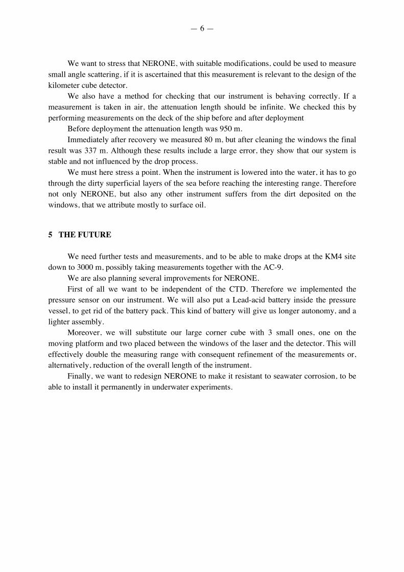
A1 THE MOTOR The motor system has been designed and built at LNF. The structure is a thin oil filled PVC cylindrical container, 10 cm diameter and 20 cm
length, with a rubber membrane to equalize the inside and outside pressures and to allow for thermal expansion of the oil. This allows the motor to operate at any depth independently of the outside pressure. The motor itself is a standard stepper motor, therefore it has no sliding contacts and it can operate normally in an oil environment. A standard rubber gasket seals the motor axis from the water.
A magnet on the spindle and a Hall sensor mounted on the body allow the operator to check the effective movement of the motor, giving the actual revolution count and avoiding slipping.
The motor system has been tested in the LNS pressure chamber and it operated correctly down to 3500 meters.
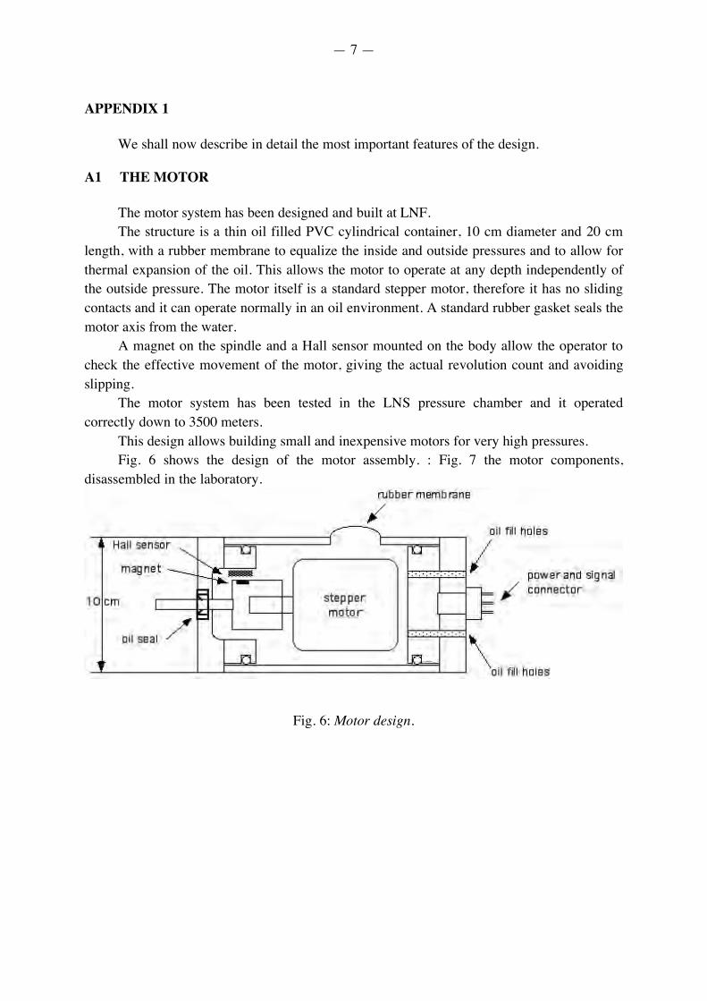
This design allows building small and inexpensive motors for very high pressures. Fig. 6 shows the design of the motor assembly. : Fig. 7 the motor components,
disassembled in the laboratory.
Fig. 6: Motor design.
— 8 —
Fig. 7: The motor components, disassembled in the laboratory.
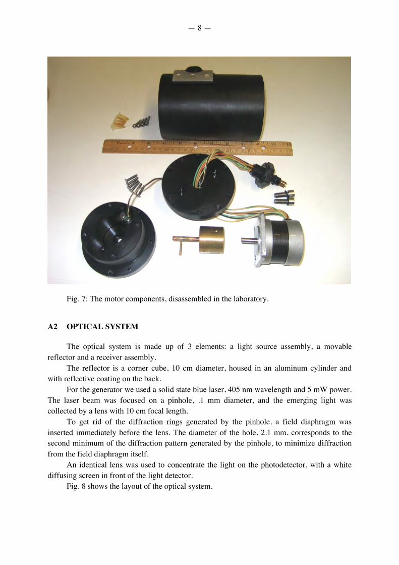
A2 OPTICAL SYSTEM
The optical system is made up of 3 elements: a light source assembly, a movable
reflector and a receiver assembly. The reflector is a corner cube, 10 cm diameter, housed in an aluminum cylinder and
with reflective coating on the back. For the generator we used a solid state blue laser, 405 nm wavelength and 5 mW power.
The laser beam was focused on a pinhole, .1 mm diameter, and the emerging light was collected by a lens with 10 cm focal length.
To get rid of the diffraction rings generated by the pinhole, a field diaphragm was inserted immediately before the lens. The diameter of the hole, 2.1 mm, corresponds to the second minimum of the diffraction pattern generated by the pinhole, to minimize diffraction from the field diaphragm itself.
An identical lens was used to concentrate the light on the photodetector, with a white diffusing screen in front of the light detector.
Fig. 8 shows the layout of the optical system.
— 9 —
Fig. 8: Optical system.
Two photodetectors have been used: one for the light detector and one mounted laterally in the laser housing, to get rid of the laser intensity fluctuations, which did not allow enough precision in the measurements. A3 DATA ACQUISITION SYSTEM
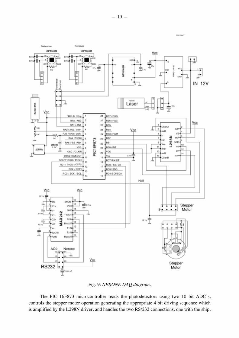
The data acquisition system and the motor control have been designed and built at LNF. The board is based on a PIC 16F873 microcontroller, that reads the photodetectors and the pressure sensor through embedded 10 bit ADC’s, sends out the averaged data on the RS/232 link to the ship, and receives commands to move the motor. Fig. 9 shows the electronics diagram.
— 10 —
Fig. 9: NERONE DAQ diagram.
The PIC 16F873 microcontroller reads the photodetectors using two 10 bit ADC’s, controls the stepper motor operation generating the appropriate 4 bit driving sequence which is amplified by the L298N driver, and handles the two RS/232 connections, one with the ship,
— 11 —
receiving commands and transmitting the measured data, all in ASCII format, and the other with a separate channel going to the AC9, which is the instruments used up to now to measure light transmission. It is possible from the ship to put the NERONE system in a Transparent mode, thereby connecting to the AC9 and allowing to take measurements with both instruments during the same deployment to compare results.
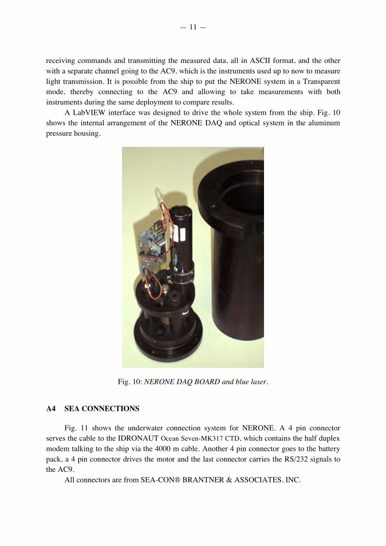
A LabVIEW interface was designed to drive the whole system from the ship. Fig. 10 shows the internal arrangement of the NERONE DAQ and optical system in the aluminum pressure housing.
Fig. 10: NERONE DAQ BOARD and blue laser. A4 SEA CONNECTIONS
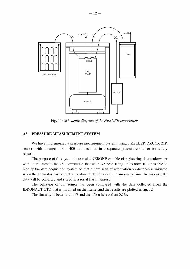
Fig. 11 shows the underwater connection system for NERONE. A 4 pin connector
serves the cable to the IDRONAUT Ocean Seven-MK317 CTD, which contains the half duplex modem talking to the ship via the 4000 m cable. Another 4 pin connector goes to the battery pack, a 4 pin connector drives the motor and the last connector carries the RS/232 signals to the AC9.
All connectors are from SEA-CON® BRANTNER & ASSOCIATES, INC.
— 12 —
Fig. 11: Schematic diagram of the NERONE connections.
A5 PRESSURE MEASUREMENT SYSTEM
We have implemented a pressure measurement system, using a KELLER-DRUCK 21R
sensor, with a range of 0 - 400 atm installed in a separate pressure container for safety reasons.
The purpose of this system is to make NERONE capable of registering data underwater without the remote RS-232 connection that we have been using up to now. It is possible to modify the data acquisition system so that a new scan of attenuation vs distance is initiated when the apparatus has been at a constant depth for a definite amount of time. In this case, the data will be collected and stored in a serial flash memory.
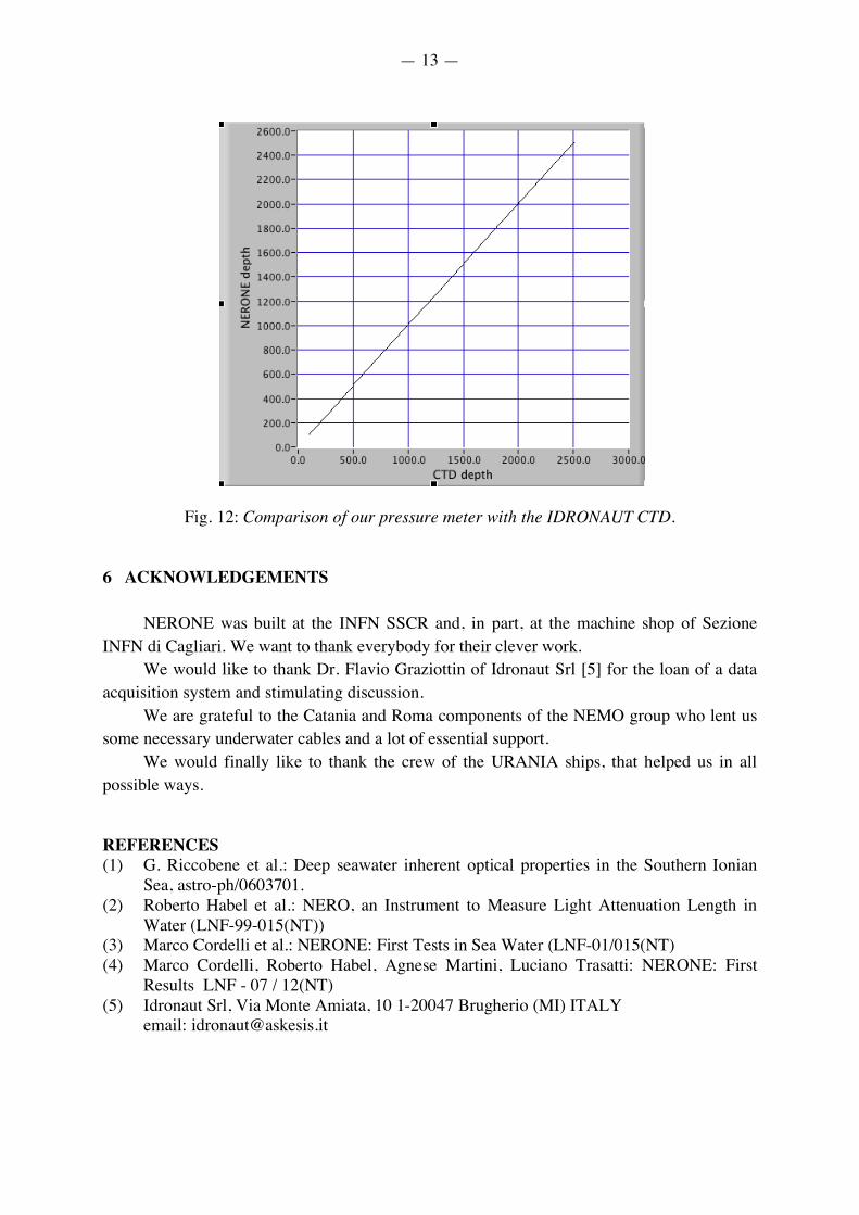
The behavior of our sensor has been compared with the data collected from the IDRONAUT CTD that is mounted on the frame, and the results are plotted in fig. 12.
The linearity is better than 1% and the offset is less than 0.5%.
— 13 —
Fig. 12: Comparison of our pressure meter with the IDRONAUT CTD. 6 ACKNOWLEDGEMENTS
NERONE was built at the INFN SSCR and, in part, at the machine shop of Sezione
INFN di Cagliari. We want to thank everybody for their clever work. We would like to thank Dr. Flavio Graziottin of Idronaut Srl [5] for the loan of a data
acquisition system and stimulating discussion. We are grateful to the Catania and Roma components of the NEMO group who lent us
some necessary underwater cables and a lot of essential support. We would finally like to thank the crew of the URANIA ships, that helped us in all
possible ways. REFERENCES (1) G. Riccobene et al.: Deep seawater inherent optical properties in the Southern Ionian
Sea, astro-ph/0603701. (2) Roberto Habel et al.: NERO, an Instrument to Measure Light Attenuation Length in
Water (LNF-99-015(NT)) (3) Marco Cordelli et al.: NERONE: First Tests in Sea Water (LNF-01/015(NT) (4) Marco Cordelli, Roberto Habel, Agnese Martini, Luciano Trasatti: NERONE: First
Results LNF - 07 / 12(NT) (5) Idronaut Srl, Via Monte Amiata, 10 1-20047 Brugherio (MI) ITALY
email: [email protected]