
Neousys Technology Inc. POC-200 Series - ACCEED · POC-200 Series User’s Manual Neousys...
78
POC-200 Series User’s Manual Copyright © 2014 Neousys Technology Inc. All Right Reserved. Page 1 of 78 Neousys Technology Inc. POC-200 Series Ultra-compact Atom™ Bay Trail-I Fanless Embedded Controller with PoE and USB 3.0 User’s Manual Rev. A1.1 Published Sep 24 th , 2014
Transcript of Neousys Technology Inc. POC-200 Series - ACCEED · POC-200 Series User’s Manual Neousys...

POC-200 Series User’s Manual
Copyright © 2014 Neousys Technology Inc. All Right Reserved. Page 1 of 78
Neousys Technology Inc.
POC-200 Series
Ultra-compact Atom™ Bay Trail-I
Fanless Embedded Controller with PoE and USB 3.0
User’s Manual
Rev. A1.1
Published Sep 24th, 2014

POC-200 Series User’s Manual
Copyright © 2014 Neousys Technology Inc. All Right Reserved. Page 2 of 78
Date Description Version
2014/09/24 Modify 5V TTL GPIO Pin Define, Page 21,75 A1.1

POC-200 Series User’s Manual
Copyright © 2014 Neousys Technology Inc. All Right Reserved. Page 3 of 78
Contents
Declaimer ............................................................................................................................. 6
Declaration of Conformity ............................................................................................. 6
FCC ................................................................................................................... 6
CE ...................................................................................................................... 6
Copyright and Trademarks ........................................................................................... 6
Chapter 1 Introduction ......................................................................................................... 7
1.1 Overview ................................................................................................................. 7
1.2 Product Specification .............................................................................................. 8
1.2.1 Specification of POC-200 .......................................................................... 8
1.2.2 Specification of POC-210 .......................................................................... 9
1.2.3 Specification of POC-212 ........................................................................ 10
1.2.4 Specification of POC-222 ........................................................................ 12
Chapter 2 Getting Started .................................................................................................. 14
2.1 Unpacking your POC-200 ..................................................................................... 14
2.2 Front Panel I/O Functions ..................................................................................... 15
2.2.1 Power Button .......................................................................................... 15
2.2.2 Reset Button ........................................................................................... 16
2.2.3 LED Indicators ........................................................................................ 16
2.2.4 USB 3.0 Connectors ............................................................................... 17
2.2.5 Speaker-out Jack .................................................................................... 17
2.2.6 Gigabit Ethernet Ports ............................................................................. 18
2.2.7 IEEE 802.3at PoE PSE (POC-200 Only) ................................................ 19
2.2.8 DVI-I Connector ...................................................................................... 19
2.2.9 DIO Connector ........................................................................................ 20
2.2.9.1 Isolated DIO on POC-200 ................................................................. 20
2.2.9.2 5V TTL GPIO on POC-210/POC-212/POC-222 ............................... 22
2.3 Back Panel I/O Functions ..................................................................................... 24
2.3.1 USB3.0 Connectors ................................................................................ 24
2.3.2 USB2.0 Connectors ................................................................................ 25
2.3.3 COM Ports on POC-212/222 .................................................................. 25
2.3.4 COM Ports on POC-200/210 .................................................................. 26
2.3.5 2-Pin Terminal Block for DC Input ........................................................... 27
2.4 Internal I/O Functions ........................................................................................... 29
2.4.1 Remote On/Off Control ........................................................................... 29
2.4.2 Mini PCI Express Connector and SIM Socket ......................................... 30
2.4.3 DDR3L SODIMM Socket ......................................................................... 30
2.4.4 SATA Connector ..................................................................................... 31
2.5 POC-200/210 Mechanical Dimension ................................................................... 32

POC-200 Series User’s Manual
Copyright © 2014 Neousys Technology Inc. All Right Reserved. Page 4 of 78
2.5.1 Top View ................................................................................................. 32
2.5.2 Front View ............................................................................................... 33
2.5.3 Side View ................................................................................................ 33
2.5.4 Bottom View ............................................................................................ 34
2.6 POC-212/222 Mechanical Dimension ................................................................... 35
2.6.1 Top View ................................................................................................. 35
2.6.2 Front View ............................................................................................... 36
2.6.3 Side View ................................................................................................ 36
2.6.4 Bottom View ............................................................................................ 37
Chapter 3 Getting Start ...................................................................................................... 38
3.1 Dissemble your POC-200 Series .......................................................................... 38
3.1.1 Dissemble POC-200/210 ........................................................................ 38
3.1.2 Dissemble POC-212/222 ........................................................................ 39
3.2 Install a DDR3L SODIMM Module ........................................................................ 40
3.3 Install a 2.5” HDD/SSD ......................................................................................... 41
3.3.1 Install a 2.5” HDD/SSD on POC-200/210 ................................................ 41
3.3.2 Install a 2.5” HDD/SSD on POC-212/222 ................................................ 43
3.4 Install a Mini-PCIe Module .................................................................................... 44
3.4.1 Install a Mini-PCIe Module on POC-200/POC-210 ................................. 44
3.4.2 Install a Mini-PCIe Module on POC-212/222 .......................................... 46
3.5 Mount your POC-200 Series ................................................................................. 48
3.5.1 Suspend your POC-200 on the Wall ....................................................... 48
3.5.2 Mount your POC-200 Outside-in on a Surface ........................................ 49
3.5.3 Mount your POC-212/222 Inside-out on a Surface ................................. 50
3.5.4 Mount your POC-200 on the DIN Rail ..................................................... 51
3.6 Connect DC power to you POC-200 ..................................................................... 52
3.7 Power on your POC-200 ....................................................................................... 53
3.7.1 To Power on POC-200 Using the Power Button ..................................... 53
3.7.2 To Power on POC-200 Using an Latched Switch (AT-mode) ................. 54
3.7.3 To Power on POC-200 Using an Non-latched Switch (ATX-mode) ........ 55
3.7.4 To Power on POC-200 Using Wake-on-LAN Function............................ 56
Chapter 4 BIOS and Driver ................................................................................................ 59
4.1 BIOS Settings ....................................................................................................... 59
4.1.1 COM1 Operation Mode ........................................................................... 59
4.1.2 COM3 Operation Mode (POC-200/210 Only) ......................................... 60
4.1.3 Chipset SATA Mode................................................................................ 61
4.1.4 C-States and Max C-States .................................................................... 61
4.1.5 Wake-on-LAN Option .............................................................................. 62
4.1.6 Power On after Power Failure Option ..................................................... 63
4.1.7 Watchdog Timer for Booting ................................................................... 63

POC-200 Series User’s Manual
Copyright © 2014 Neousys Technology Inc. All Right Reserved. Page 5 of 78
4.1.8 Select a Boot Device ............................................................................... 64
4.2 Operating System Support ................................................................................... 66
4.3 Driver Installation .................................................................................................. 67
4.3.1 Install All Drivers Using “One-Click” Driver Installation ........................... 67
4.3.2 Install Drivers Manually ........................................................................... 68
Appendix A Using Watchdog Timer and DIO ..................................................................... 70
Install WDT and DIO Library ....................................................................................... 70
Using WDT Function ................................................................................................... 72
WDT Function Reference ................................................................................ 72
InitWDT ........................................................................................................ 72
SetWDT ........................................................................................................ 72
StartWDT ...................................................................................................... 73
ResetWDT .................................................................................................... 73
StopWDT ...................................................................................................... 74
Using DIO Function .................................................................................................... 74
Wiring for Isolated DIO (POC-200 Only) .......................................................... 74
Pin Definition for Isolated DIO (POC-200 Only) ............................................... 75
Pin Definition for 5V TTL GPIO (POC-210/212/222) ........................................ 76
DIO Function Reference .................................................................................. 76
InitDIO .......................................................................................................... 76
DIReadLine .................................................................................................. 77
DIReadPort ................................................................................................... 77
DOWriteLine ................................................................................................. 77
DOWritePort ................................................................................................. 78

POC-200 Series User’s Manual
Copyright © 2014 Neousys Technology Inc. All Right Reserved. Page 6 of 78
Declaimer
This manual is intended to be used as a practical and informative guide only and is subject
to change without prior notice. It does not represent commitment from Neousys Technology
Inc. Neousys shall not be liable for direct, indirect, special, incidental, or consequential
damages arising out of the use of the product or documentation, nor for any infringements
upon the rights of third parties, which may result from such use.
Declaration of Conformity
FCC
This equipment has been tested and found to comply with the limits for a Class A digital
device, pursuant to part 15 of the FCC Rules. These limits are designed to provide
reasonable protection against harmful interference when the equipment is operated in a
commercial environment. This equipment generates, uses, and can radiate radio frequency
energy and, if not installed and used in accordance with the instruction manual, may cause
harmful interference to radio communications. Operation of this equipment in a residential
area is likely to cause harmful interference in which case the user will be required to correct
the interference at his own expense.
CE
The product(s) described in this manual complies with all applicable European Union (CE)
directives if it has a CE marking. For computer systems to remain CE compliant, only
CE-compliant parts may be used. Maintaining CE compliance also requires proper cable
and cabling techniques.
Copyright and Trademarks This document contains proprietary information protected by copyright. All rights are
reserved. No part of this document may be reproduced by any mechanical, electronic, or
other means in any form without prior written permission of the manufacturer.
Company/product names mentioned herein are used for identification purposes only and
are trademarks and/or registered trademarks of their respective companies.

POC-200 Series User’s Manual
Copyright © 2014 Neousys Technology Inc. All Right Reserved. Page 7 of 78
Chapter 1 Introduction
1.1 Overview POC-200 series is a breakthrough of Neousys’ ultra-compact controller series. Inheriting
the concept of favorable POC-100, POC-200 series further incorporates greater computing
power and more versatile functions in its 3.5” HDD footprint.
The new Intel® Atom™ Bay Trail-I platform brings a leaping for both arithmetic and
graphics performance. With Atom™ E3845 quad-core processor, POC-200 can deliver
more than 200% performance over previous D525/D2550 platform. It also feature
comprehensive I/O interfaces to make use of the advance of computing power. Two Gigabit
Ethernet and three USB 3.0 ports are integrated so you can connect GigE/USB3 cameras
for vision applications. Its IEEE 802.3at PoE option is capable to supply 25.5W each port to
power you IP camera for surveillance applications. POC-200 series also features up to four
COM ports and digital I/O for general-purpose industrial applications.
Size is another attractive feature of POC-200. Its 6”x4” footprint makes installation of
POC-200 extremely easy. And its -30°C to 70°C operating temperature eliminates the
restriction for deployment environment. Neousys provides derivative models with different
CPU and I/O configuration so you can always find a fit POC-200 for your application.

POC-200 Series User’s Manual
Copyright © 2014 Neousys Technology Inc. All Right Reserved. Page 8 of 78
1.2 Product Specification
1.2.1 Specification of POC-200
System Core
Processor Intel® Atom™ E3845 1.91 GHz quad-core processor
Graphics Integrated Intel® HD Graphics
Memory 1x SODIMM socket for DDR3L-1333, up to 8GB
Panel I/O Interface
Ethernet 2x Gigabit Ethernet ports by Intel® I210 GbE controller
PoE IEEE 802.3at PoE PSE (25.5W each GbE port))
Video Port 1x DVI-I connector for both analog RGB and DVI/HDMI outputs, supporting up to
2560 x 1600 resolution
Serial Port 2x software-programmable RS-232/422/485 (COM1 & COM3)
2x RS-232 (COM2 & COM4)
USB
1x USB 3.0 port via native USB3 controller
2x USB 3.0 ports via Renasas uPD720202 USB3 host controller
1x USB 2.0 port
Audio 1x Speaker-out
DIO 4-CH isolated DI + 4-CH isolated DO
Internal I/O Interface
Mini-PCIe 1x mini PCI Express slot with USIM socket
Storage Interface
SATA HDD 1x internal SATA port for 2.5” HDD/SSD
Power Supply
DC Input Built-in 8~35 VDC DC input
Input Connector 2-pin pluggable terminal block for DC input
Power Consumption Typical: 7.68W (0.32A@24V)
Full-loading: 13.44W (0.56A@24V)*
Mechanical
Dimension 149mm (W) x 105 mm (H) x 58 mm (D)
Weight 1.1 kg (with one 2.5” SATA HDD)
Mounting Wall-mount (Standard)
DIN-rail mount (Optional)
Environmental
Operating
Temperature
-30°C ~ 70°C with SSD, 100% CPU loading **/***
-10°C ~ 60°C with HDD, 100% CPU loading **/***

POC-200 Series User’s Manual
Copyright © 2014 Neousys Technology Inc. All Right Reserved. Page 9 of 78
Storage
Temperature -40°C ~85°C
Humidity 10%~90% , non-condensing
Vibration Operating, 5 Grms, 5-500 Hz, 3 Axes (w/ SSD, w/o add-on card, according to
Shock Operating, 50 Grms, Half-sine 11 ms Duration (w/ SSD, w/o add-on card, according
to IEC60068-2-27)
EMC CE/FCC Class A, according to EN 55022 & EN 55024
* Full-loading power consumption is measured with 2GB DDR3 memory and one 2.5” SATA HDD installed under the
following conditions:
- 100% loading for Atom E3845 CPU
- 100% loading for 3D graphics
- 100% loading for GbE port
** The 100% CPU loading is applied using Passmark® BurnInTest™ v7.0. For detail testing criteria, please contact
Neousys Technology
*** For sub-zero operating temperature, wide-temperature DDR3-L and wide-temperature HDD/SSD are required.
1.2.2 Specification of POC-210
System Core
Processor Intel® Atom™ E3845 1.91 GHz quad-core processor
Graphics Integrated Intel® HD Graphics
Memory 1x SODIMM socket for DDR3L-1333, up to 8GB
Panel I/O Interface
Ethernet 2x Gigabit Ethernet ports by Intel® I210 GbE controller
PoE N/A
Video Port 1x DVI-I connector for both analog RGB and DVI/HDMI outputs, supporting up to
2560 x 1600 resolution
Serial Port 2x software-programmable RS-232/422/485 (COM1 & COM3)
2x RS-232 (COM2 & COM4)
USB
1x USB 3.0 port via native USB3 controller
2x USB 3.0 ports via Renasas uPD720202 USB3 host controller
1x USB 2.0 port
Audio 1x Speaker-out
DIO 4-CH 5V TTL DI + 4-CH 5V TTL DO
Internal I/O Interface
Mini-PCIe 1x mini PCI Express slot with USIM socket
Storage Interface
SATA HDD 1x internal SATA port for 2.5” HDD/SSD
Power Supply
DC Input Built-in 8~35 VDC DC input

POC-200 Series User’s Manual
Copyright © 2014 Neousys Technology Inc. All Right Reserved. Page 10 of 78
Input Connector 2-pin pluggable terminal block for DC input
Power Consumption Typical: 7.68W (0.32A@24V)
Full-loading: 13.44W (0.56A@24V)*
Mechanical
Dimension 149mm (W) x 105 mm (H) x 58 mm (D)
Weight 1.1 kg (with one 2.5” SATA HDD)
Mounting Wall-mount (Standard)
DIN-rail mount (Optional)
Environmental
Operating
Temperature
-30°C ~ 70°C with SSD, 100% CPU loading **/***
-10°C ~ 60°C with HDD, 100% CPU loading **/***
Storage
Temperature -40°C ~85°C
Humidity 10%~90% , non-condensing
Vibration Operating, 5 Grms, 5-500 Hz, 3 Axes (w/ SSD, w/o add-on card, according to
Shock Operating, 50 Grms, Half-sine 11 ms Duration (w/ SSD, w/o add-on card, according
to IEC60068-2-27)
EMC CE/FCC Class A, according to EN 55022 & EN 55024
* Full-loading power consumption is measured with 2GB DDR3 memory and one 2.5” SATA HDD installed under the
following conditions:
- 100% loading for Atom E3845 CPU
- 100% loading for 3D graphics
- 100% loading for GbE port
** The 100% CPU loading is applied using Passmark® BurnInTest™ v7.0. For detail testing criteria, please contact
Neousys Technology
*** For sub-zero operating temperature, wide-temperature DDR3-L and wide-temperature HDD/SSD are required.
1.2.3 Specification of POC-212
System Core
Processor Intel® Atom™ E3845 1.91 GHz quad-core processor
Graphics Integrated Intel® HD Graphics
Memory 1x SODIMM socket for DDR3L-1333, up to 8GB
Panel I/O Interface
Ethernet 2x Gigabit Ethernet ports by Intel® I210 GbE controller
PoE N/A
Video Port 1x DVI-I connector for both analog RGB and DVI/HDMI outputs, supporting up to
2560 x 1600 resolution
Serial Port 1x software-programmable RS-232/422/485 (COM1)
1x RS-232 (COM2)

POC-200 Series User’s Manual
Copyright © 2014 Neousys Technology Inc. All Right Reserved. Page 11 of 78
USB
1x USB 3.0 port via native USB3 controller
2x USB 3.0 ports via Renasas uPD720202 USB3 host controller
1x USB 2.0 port
Audio 1x Speaker-out
DIO 4-CH 5V TTL DI + 4-CH 5V TTL DO
Internal I/O Interface
Mini-PCIe 1x mini PCI Express slot with USIM socket
Storage Interface
SATA HDD 1x internal SATA port for 2.5” HDD/SSD
Power Supply
DC Input Built-in 8~35 VDC DC input
Input Connector 2-pin pluggable terminal block for DC input
Power Consumption Typical: 7.68W (0.32A@24V)
Full-loading: 13.44W (0.56A@24V)*
Mechanical
Dimension 149mm (W) x 105 mm (H) x 54 mm (D)
Weight 1.1 kg (with one 2.5” SATA HDD)
Mounting Wall-mount (Standard)
DIN-rail mount (Optional)
Environmental
Operating
Temperature
-30°C ~ 70°C with SSD, 100% CPU loading **/***
-10°C ~ 60°C with HDD, 100% CPU loading **/***
Storage
Temperature -40°C ~85°C
Humidity 10%~90% , non-condensing
Vibration Operating, 5 Grms, 5-500 Hz, 3 Axes (w/ SSD, w/o add-on card, according to
Shock Operating, 50 Grms, Half-sine 11 ms Duration (w/ SSD, w/o add-on card, according
to IEC60068-2-27)
EMC CE/FCC Class A, according to EN 55022 & EN 55024
* Full-loading power consumption is measured with 2GB DDR3 memory and one 2.5” SATA HDD installed under the
following conditions:
- 100% loading for Atom E3845 CPU
- 100% loading for 3D graphics
- 100% loading for GbE port
** The 100% CPU loading is applied using Passmark® BurnInTest™ v7.0. For detail testing criteria, please contact
Neousys Technology
*** For sub-zero operating temperature, wide-temperature DDR3-L and wide-temperature HDD/SSD are required.

POC-200 Series User’s Manual
Copyright © 2014 Neousys Technology Inc. All Right Reserved. Page 12 of 78
1.2.4 Specification of POC-222
System Core
Processor Intel® Atom™ E3825 1.33 GHz dual-core processor
Graphics Integrated Intel® HD Graphics
Memory 1x SODIMM socket for DDR3L-1067, up to 4GB
Panel I/O Interface
Ethernet 2x Gigabit Ethernet ports by Intel® I210 GbE controller
PoE N/A
Video Port 1x DVI-I connector for both analog RGB and DVI/HDMI outputs, supporting up to
2560 x 1600 resolution
Serial Port 1x software-programmable RS-232/422/485 (COM1)
1x RS-232 (COM2)
USB
1x USB 3.0 port via native USB3 controller
2x USB 3.0 ports via Renasas uPD720202 USB3 host controller
1x USB 2.0 port
Audio 1x Speaker-out
DIO 4-CH 5V TTL DI + 4-CH 5V TTL DO
Internal I/O Interface
Mini-PCIe 1x mini PCI Express slot with USIM socket
Storage Interface
SATA HDD 1x internal SATA port for 2.5” HDD/SSD
Power Supply
DC Input Built-in 8~35 VDC DC input
Input Connector 2-pin pluggable terminal block for DC input
Power Consumption Typical: 7.27W (0.30A@24V)
Full-loading: 9.60W (0.40A@24V)*
Mechanical
Dimension 149mm (W) x 105 mm (H) x 54 mm (D)
Weight 1.1 kg (with one 2.5” SATA HDD)
Mounting Wall-mount (Standard)
DIN-rail mount (Optional)
Environmental
Operating
Temperature
-30°C ~ 70°C with SSD, 100% CPU loading **/***
-10°C ~ 60°C with HDD, 100% CPU loading **/***
Storage
Temperature -40°C ~85°C
Humidity 10%~90% , non-condensing

POC-200 Series User’s Manual
Copyright © 2014 Neousys Technology Inc. All Right Reserved. Page 13 of 78
Vibration Operating, 5 Grms, 5-500 Hz, 3 Axes (w/ SSD, w/o add-on card, according to
Shock Operating, 50 Grms, Half-sine 11 ms Duration (w/ SSD, w/o add-on card, according
to IEC60068-2-27)
EMC CE/FCC Class A, according to EN 55022 & EN 55024
* Full-loading power consumption is measured with 2GB DDR3 memory and one 2.5” SATA HDD installed under the
following conditions:
- 100% loading for Atom E3845 CPU
- 100% loading for 3D graphics
- 100% loading for GbE port
** The 100% CPU loading is applied using Passmark® BurnInTest™ v7.0. For detail testing criteria, please contact
Neousys Technology
*** For sub-zero operating temperature, wide-temperature DDR3-L and wide-temperature HDD/SSD are required.

POC-200 Series User’s Manual
Copyright © 2014 Neousys Technology Inc. All Right Reserved. Page 14 of 78
Chapter 2 Getting Started
2.1 Unpacking your POC -200 When you receive the package of POC-200 series, please check immediately if the
package contains all the items listed in the following table. If any item is missing or
damaged, please contact your local dealer or Neousys Technology Inc. for further
assistance.
Item Description Qty
1 POC-200/210/212/222 ultra-compact fanless controller
(According to the configuration you order, your POC-200 may contain
DDR3L module or SATA HDD. Please verify these items if necessary.)
1
2 Specialized DVI-to-VGA adapter for POC-200 1
3 2-pin pluggable terminal block 1
4 Neousys Drivers & Utilities DVD 1
5 Screw package 1

POC-200 Series User’s Manual
Copyright © 2014 Neousys Technology Inc. All Right Reserved. Page 15 of 78
2.2 Front Panel I/O Functions On POC-200 series, we design general-purpose I/O functions on the front panel so you can
easily access them. In this section, we’ll illustrate each I/O function on the front panel.
2.2.1 Power Button
The power button is a non-latched switch for ATX mode on/off operation. To turn on the
POC-200, press the power button and the PWR LED on the center-top side is lighted up.
To turn off the POC-200, you can either issue a shutdown command in OS, or just simply
press the power button. In case of system halts, you can press and hold the power button
for 5 seconds to compulsorily shut down the system. Please note that a 5 seconds interval
is kept by the system between two on/off operations (i.e. once turning off the system, you
shall wait for 5 seconds to initiate another power-on operation).

POC-200 Series User’s Manual
Copyright © 2014 Neousys Technology Inc. All Right Reserved. Page 16 of 78
2.2.2 Reset Button
The reset button is used to manually reset the system in case of any abnormal condition.
To avoid unexpected operation, the reset button is hidden behind the front panel. You need
to use a pin-like object to push the reset button.
2.2.3 LED Indicators
There are three LED indicators on the front panel: PWR, WDT and HDD. The descriptions
of these three LED are listed in the following table.
Indicator Color Description
PWR Green Power indictor, lighted-up when system is on, off when system is
off.
WDT Yellow Watchdog timer indicator, flashing when watchdog timer is started.
HDD Red Hard drive indicator, flashing when SATA hard drive is active.

POC-200 Series User’s Manual
Copyright © 2014 Neousys Technology Inc. All Right Reserved. Page 17 of 78
2.2.4 USB 3.0 Connectors
There are totally three USB 3.0 ports and one USB 2.0 port on POC-200 series. Two of
three USB 3.0 ports are located on the front panel. They are implemented via a Renasas
uPD720202 USB3 host controller. By BIOS default, these USB ports are operated in xHCI
(eXtensible Host Control Interface) mode and are compatible to USB 3.0, USB 2.0, USB
1.1 and USB 1.0 devices. Legacy USB support on these ports is provided only when “xHCI
Mode” option in BIOS is configured as “Smart Auto”.
To utilize USB 3.0 function in Windows, you need to install corresponding driver for
Renasas uPD720202 USB3.0 controller. Please refer to section 4.3 for information of driver
installation.
2.2.5 Speaker-out Jack
POC-200 series provides speaker-out function using Intel® High Definition Audio (built-in in
ICH8-M) and Realtek ALC262 codec. An audio jack is located on the front panel. To utilize

POC-200 Series User’s Manual
Copyright © 2014 Neousys Technology Inc. All Right Reserved. Page 18 of 78
the speaker-out function in Windows, you need to install corresponding drivers for both
Intel® ICH8-M chipset and Realtek ALC262 codec. Please refer to section 4.3 for
information of driver installation.
2.2.6 Gigabit Ethernet Ports
POC-200 series offers two Gigabit Ethernet ports using Intel® I210 GbE controller. When
plugging in the Ethernet cable, you can tell the Ethernet status and speed from the LED
indicators on the RJ45 connector as following:
Active/Link LED LED Color Status Description Yellow Off Ethernet port is disconnected
On Ethernet port is connected and no data transmission Flashing Ethernet port is connected and data is transmitting/receiving
Speed LED LED Color Status Description Green or Orange
Off 10 Mbps Green 100 Mbps Orange 1000 Mbps
To utilize the GbE port in Windows, you need to install corresponding driver for Intel® I210
GbE controller. Please refer to 4.3 for information of driver installation.

POC-200 Series User’s Manual
Copyright © 2014 Neousys Technology Inc. All Right Reserved. Page 19 of 78
2.2.7 IEEE 802.3at PoE PSE (POC-200 Only)
PoE, or Power over Ethernet, is a technology to supply electrical power along with data on
a standard CAT-5/CAT-6 Ethernet cable. Two Gigabit Ethernet ports on POC-200 support
IEEE 802.3at PoE PSE (Power Sourcing Equipment) function. Each PoE port can deliver
25.5 W of power to a PoE PD (Powered Device), such as a PoE IP camera or a PoE WIFI
AP. PoE defines a mechanism to automatically detect the device connected and determine
whether to dispatch power. This makes PoE port 100% compatible with traditional Ethernet
devices thus you can use these ports to connect PoE or non-PoE devices.
2.2.8 DVI-I Connector
POC-200 series features a DVI-I connector on its front panel to output both VGA and
DVI/HDMI signals. The DVI/HDMI and VGA outputs are directly driven by integrated Intel
HD Graphics engine and support up to 2560 x 1600 resolution.

POC-200 Series User’s Manual
Copyright © 2014 Neousys Technology Inc. All Right Reserved. Page 20 of 78
For VGA monitor, Neousys offers a specialized DVI-to-VGA adapter as an accessory
shipped with POC-200 series. This adapter supports VGA DDC signals and thus eliminates
compatibility issues with VGA monitors. Or you can use a DVI-I to VGA+DVI-D Y-cable to
support two independent display outputs.
DVI-to-VGA Adapter DVI-I to VGA+DVI-D Y-Cabl e
To have best graphics performance in Windows, you need to install corresponding graphics
driver. Please refer to section 4.3 for information of driver installation.
2.2.9 DIO Connector
2.2.9.1 Isolated DIO on POC-200
POC-200 integrates 2500Vrms isolated DIO function for extending application range. This
feature provides 4 channels of isolated digital input and 4 channels of isolated digital output
via a 16-pin box-header connector. The following table describes the pin definition of
isolated DIO connector.

POC-200 Series User’s Manual
Copyright © 2014 Neousys Technology Inc. All Right Reserved. Page 21 of 78
Pin Definition
Pin# Definition I/O Description
1 ISO_5V O Isolate 5V power supply
2 VDD I DO voltage source input for inductive load
3 DI_0 I Digital input channel 0
4 VDD I DO voltage source input for inductive load
5 DI_1 I Digital input channel 1
6 DO_0 O Digital output channel 0
7 DI_GND - Digital input GND
8 DO_1 O Digital output channel 1
9 DI_2 I Digital input channel 2
10 DO_GND - Digital output GND
11 DI_3 I Digital input channel 3
12 DO_2 O Digital output channel 2
13 DI_GND - Digital input GND
14 DO_3 O Digital output channel 3
15 DI_GND - Digital input signal
16 DO_GND - Digital output GND
Electrical Characteristics
Parameeter Description Min Typ Max
DO Channel [0:3]
V_DO DO output voltage 24 V
I_DO DO current limit 100 250 mA
DI Channel [0:3]
V_DI High Input voltage High 5 24 V
V_DI Low Input voltage Low 0 1.5 V
I_DI Input current 20 mA
Voltage ISO_5V
V_ISO5V Voltage 4.75 5 5.25 V

POC-200 Series User’s Manual
Copyright © 2014 Neousys Technology Inc. All Right Reserved. Page 22 of 78
I_ISO5V Current 200 mA
Input Parameter
Resistor Input resistor 2.4 Kohm
Isolated voltage 2500 V rms
2.2.9.2 5V TTL GPIO on POC-210/POC-212/POC-222
POC-210/212/222 offers 8-CH 5V TTL GPIO for general-purpose usage. By default, these
channels are configured as 4 channels of digital input and 4 channels of digital output. The
following table describes the pin definition of isolated DIO connector.
Pin Definition
Pin# Definition I/O Description
1 N.C - No connection
2 N.C - No connection
3 DI_0 I Digital input channel 0
4 N.C. - No connection
5 DI_1 I Digital input channel 1
6 DO_0 O Digital output channel 0
7 N.C. - No connection

POC-200 Series User’s Manual
Copyright © 2014 Neousys Technology Inc. All Right Reserved. Page 23 of 78
8 DO_1 O Digital output channel 1
9 DI_2 I Digital input channel 2
10 D_GND GND Digital GND
11 DI_3 I Digital input channel 3
12 DO_2 O Digital output channel 2
13 N.C. - No connection
14 DO_3 O Digital output channel 3
15 N.C. - No connection
16 D_GND GND Digital GND

POC-200 Series User’s Manual
Copyright © 2014 Neousys Technology Inc. All Right Reserved. Page 24 of 78
2.3 Back Panel I/O Functions To fit more general application requirements, POC-200 series offers more I/O functions on
its back panel. In this section, we’ll illustrate each I/O function on the back panel.
2.3.1 USB3.0 Connectors
There are totally three USB 3.0 ports and one USB 2.0 port on POC-200 series. One of
three USB 3.0 ports is located on the back panel. This USB 3.0 port is implemented via
native xHCI controller inside Bay Trail SoC. By BIOS default, this USB port is operated in
xHCI (eXtensible Host Control Interface) mode and is compatible to USB 3.0, USB 2.0,
USB 1.1 and USB 1.0 devices.
To utilize USB 3.0 function in Windows, you need to install corresponding USB3 driver for
Bay Trail SoC. Please refer to section 4.3 for information of driver installation.

POC-200 Series User’s Manual
Copyright © 2014 Neousys Technology Inc. All Right Reserved. Page 25 of 78
2.3.2 USB2.0 Connectors
In addition to three USB 3.0 ports, POC-200 series provides another USB 2.0 port on its
back panel. By BIOS default, these USB 2.0 ports are operated in EHCI (Enhanced Host
Control Interface) mode and are compatible with USB 2.0, USB 1.1 and USB 1.0 devices.
Legacy USB support is provided so you can use USB keyboard/mouse in DOS
environment.
2.3.3 COM Ports on POC-212/222
POC-212 and POC-222 provide two COM ports via two 9-pin D-Sub male connectors on
the back panel for communicating with external devices. They are implemented using
industrial-grade ITE8783 Super IO chip (-40 to 85°C) and provide up to 115200 bps baud
rate.
COM1 is a software-selectable RS-232/422/485 port and COM2 supports RS-232 only. The
operation mode of COM1 can be set in BIOS setup utility (refer to section 4.1.1 for detail).
The following table describes the pin definition of COM ports.

POC-200 Series User’s Manual
Copyright © 2014 Neousys Technology Inc. All Right Reserved. Page 26 of 78
COM1 COM2
Pin# RS-232 Mode RS-422 Mode RS-485 Mode
(Two-wire 485) RS-232 Mode
1 DCD DCD
2 RX 422 TXD+ 485 TXD+/RXD+ RX
3 TX 422 RXD+ TX
4 DTR 422 RXD- DTR
5 GND GND GND GND
6 DSR DSR
7 RTS RTS
8 CTS 422 TXD- 485 TXD-/RXD- CTS
9 RI RI
2.3.4 COM Ports on POC-200/210
POC-200 and POC-210 provide four COM ports via four 9-pin D-Sub male connectors on
the back panel for communicating with external devices. They are implemented using
industrial-grade ITE8783 Super IO chip (-40 to 85°C) and provide up to 115200 bps baud
rate.
COM1/COM3 are software-selectable RS-232/422/485 ports and COM2/COM4 support
RS-232 only. The operation mode of COM1/COM3 can be set in BIOS setup utility (refer to
section 4.1.1/4.1.2 for detail). The following table describes the pin definition of COM ports.

POC-200 Series User’s Manual
Copyright © 2014 Neousys Technology Inc. All Right Reserved. Page 27 of 78
COM1/COM3 COM2/COM4
Pin# RS-232 Mode RS-422 Mode RS-485 Mode
(Two-wire 485) RS-232 Mode
1 DCD DCD
2 RX 422 TXD+ 485 TXD+/RXD+ RX
3 TX 422 RXD+ TX
4 DTR 422 RXD- DTR
5 GND GND GND GND
6 DSR DSR
7 RTS RTS
8 CTS 422 TXD- 485 TXD-/RXD- CTS
9 RI RI
2.3.5 2-Pin Terminal Block for DC Input
POC-200 series features a pluggable terminal block for direct DC wiring. The 2-pin
pluggable terminal block on the back panel is fit for field usage where DC power is usually
provided. It accepts a wide range of DC power input from 8 to 35V. And the screw clamping
connection of terminal block gives a very reliable way for wiring the DC power. The
following table describes the pin definition of the pluggable terminal block. For detail
information of connecting DC power, please refer to section 3.6.

POC-200 Series User’s Manual
Copyright © 2014 Neousys Technology Inc. All Right Reserved. Page 28 of 78
Pin Description
V+ Positive polarity of DC power input (8 ~ 35V).
V- Negative polarity of DC power input (usually power ground).
Caution Please make sure the voltage and polarity of DC power is correct before you connect it to POC-200.
Supplying a voltage over 35V will damage the system..

POC-200 Series User’s Manual
Copyright © 2014 Neousys Technology Inc. All Right Reserved. Page 29 of 78
2.4 Internal I/O Functions
2.4.1 Remote On/Off Control
The remote on/off control function allows users to turn on or turn off the system remotely by
connecting an external switch. This function is provided via a 1x3 pins, 2.0mm pitch pin
header.
Both AT-mode and ATX-mode on/off control are supported. For detail information of using
remote on/off control function, please refer to section 3.7.2/3.7.3.
Switch Connection for AT/ATX Mode Remote On/Off Con trol
Mode Jumper Setting
AT
ATX

POC-200 Series User’s Manual
Copyright © 2014 Neousys Technology Inc. All Right Reserved. Page 30 of 78
2.4.2 Mini PCI Express Connector and SIM Socket
POC-200 series provides an on-board Mini PCI Express socket with SIM card support.
There are plenty of off-the-shelf mini-PCIe modules with versatile capabilities. By installing
a mini-PCIe module, your system can have expanded features such as WIFI, 3G, GPS,
RAID and etc. In addition, the SIM card support makes it possible to connect your system to
Internet in wide territory through telecom operator’s GPRS/3G network.
2.4.3 DDR3L SODIMM Socket

POC-200 Series User’s Manual
Copyright © 2014 Neousys Technology Inc. All Right Reserved. Page 31 of 78
POC-200 series provides one 204-pin, SODIMM socket for memory installation. It supports
a maximal 8GB capacity by installing one low-voltage 1.35V DDR3L-1333 SODIMM
modules. For information of installing DDR3L memory modules, please refer to section 3.2
for detail.
Note Please make sure you’re installing a 1.35V DDR3L SODIMM module to POC-200. Installing a 1.5V
DDR3 SODIMM will cause system failed to boot.
2.4.4 SATA Connector
POC-200 series provides one SATA port to accommodate a 2.5” SATA hard drive inside it.
The SATA port is located on the daughter board via a 22-pin SATA connector. With the
HDD bracket shipped with POC-200 series, you can directly mount a 2.5” HDD or SSD to
this port. For information of installing a HDD/SSD to SATA port, please refer to section 3.3
for detail.

POC-200 Series User’s Manual
Copyright © 2014 Neousys Technology Inc. All Right Reserved. Page 32 of 78
2.5 POC-200/210 Mechanical Dimension
2.5.1 Top View

POC-200 Series User’s Manual
Copyright © 2014 Neousys Technology Inc. All Right Reserved. Page 33 of 78
2.5.2 Front View
2.5.3 Side View

POC-200 Series User’s Manual
Copyright © 2014 Neousys Technology Inc. All Right Reserved. Page 34 of 78
2.5.4 Bottom View

POC-200 Series User’s Manual
Copyright © 2014 Neousys Technology Inc. All Right Reserved. Page 35 of 78
2.6 POC-212/222 Mechanical Dimension
2.6.1 Top View

POC-200 Series User’s Manual
Copyright © 2014 Neousys Technology Inc. All Right Reserved. Page 36 of 78
2.6.2 Front View
2.6.3 Side View

POC-200 Series User’s Manual
Copyright © 2014 Neousys Technology Inc. All Right Reserved. Page 37 of 78
2.6.4 Bottom View

POC-200 Series User’s Manual
Copyright © 2014 Neousys Technology Inc. All Right Reserved. Page 38 of 78
Chapter 3 Getting Start
In this chapter, we’ll illustrate how to disassemble your POC-200 and install peripheral
devices. Please note that the procedures might be varied for different POC-200 models.
Please follow the correct procedures to prevent any damage on your POC-200 series.
3.1 Dissemble your POC -200 Series
3.1.1 Dissemble POC-200/210
1. Unscrew 4 hex bolts on the top of the heat sink.
2. Unscrew four M3 F-head screws on the bottom side.

POC-200 Series User’s Manual
Copyright © 2014 Neousys Technology Inc. All Right Reserved. Page 39 of 78
3. Gently slide out the assembly of case and you can see the case and the HDD bracket.
3.1.2 Dissemble POC-212/222
1. Unscrew the hand screw on the back panel.
2. Pull the 2.5” HDD bracket out of POC-212/222.

POC-200 Series User’s Manual
Copyright © 2014 Neousys Technology Inc. All Right Reserved. Page 40 of 78
3. Unscrew 4 hex bolts on the top of the heat sink.
4. Gently slide out the assembly of case.
3.2 Install a DDR3L SODIMM Module Note Please make sure you’re installing a 1.35V DDR3L SODIMM module on POC-200. Installing a 1.5V
DDR3 SODIMM will cause system failed to boot.
1. Follow the steps in section 3.1.1 (POC-200/210) or section 3.1.2 (POC-212/222) to
dissemble your POC-200 series. You can see the DDR3L socket exposed.

POC-200 Series User’s Manual
Copyright © 2014 Neousys Technology Inc. All Right Reserved. Page 41 of 78
2. Tile the DDR3L SODIMM module and insert it to the SODIMM socket. As it’s firmly
contacted with socket connectors, press it down until the clamps of the socket snap
into the latching position of SODIMM module.
3.3 Install a 2.5” HDD/SSD The SATA port of POC-200 series is located on the daughter board via a 22-pin SATA
connector. POC-200/210 and POC-212/222 feature different design of HDD mounting
bracket. To install a 2.5” HDD/SSD to your POC-200 series, please follow the steps listed
below.
3.3.1 Install a 2.5” HDD/SSD on POC-200/210
1. Follow the steps in section 3.1.1 to dissemble your POC-200/210. You can get the
HDD bracket from the chassis assembly.
2. Remove the protective firm from the thermal pad on the HDD bracket.

POC-200 Series User’s Manual
Copyright © 2014 Neousys Technology Inc. All Right Reserved. Page 42 of 78
3. Get four M3 F-head screws from the accessory box. Attach the HDD/SSD to the
bracket using four M3 F-head screws.
(Another two screws are on the opposite side)
4. Gently slide the HDD assembly into the SATA connector till they’re firmly connected.
5. Carefully push back the case and fix the chassis assembly using four M4 F-head
screws.

POC-200 Series User’s Manual
Copyright © 2014 Neousys Technology Inc. All Right Reserved. Page 43 of 78
3.3.2 Install a 2.5” HDD/SSD on POC-212/222
1. Loose the hand screw and pull out the HDD bracket.
2. Remove the protect firm from the thermal pad on the HDD bracket.
3. Get four M3 F-head screws from the accessory box. Attach the HDD/SSD to the
bracket using four M3 F-head screws.
(Another two screws are on the opposite side)
4. Gently slide the HDD assembly into the SATA connector till they’re firmly connected.

POC-200 Series User’s Manual
Copyright © 2014 Neousys Technology Inc. All Right Reserved. Page 44 of 78
5. Fasten the hand screw of POC-212/POC-222.
3.4 Install a Mini-PCIe Module POC-200 series provides one mini-PCIe connector with SIM socket to accommodate
versatile mini-PCIe modules (e.g. 3G/4G/WIFI/GPS) for further function expansion. In this
section, we’ll demonstrate how to install a mini-PCIe WIFI module and attach an antenna to
your POC-200 series. Please note that the mini-PCIe WIFI module, cable and antenna are
not part of POC-200 series and may be different according to your system configuration.
3.4.1 Install a Mini-PCIe Module on POC-200/POC-210
1. Follow the steps in section 3.1.1 to dissemble your POC-200/210. You can see the
mini-PCIe connector exposed.
2. Tilt the mini-PCIe WIFI module and insert it to the mini-PCIe port. And fix the WIFI
module with two M2.5 P-head screws.

POC-200 Series User’s Manual
Copyright © 2014 Neousys Technology Inc. All Right Reserved. Page 45 of 78
3. Attach the IPEX-to-SMA cable to the WIFI module and fix the SMA connector (on the
IPEX-to-SMA cable) to back panel.
4. Carefully push back the case and fix the chassis/HDD assembly using four M4 F-head
screws.
5. Attach the WIFI antenna to the SMA connector.

POC-200 Series User’s Manual
Copyright © 2014 Neousys Technology Inc. All Right Reserved. Page 46 of 78
3.4.2 Install a Mini-PCIe Module on POC-212/222
1. Follow the steps in section 3.1.2 to dissemble your POC-212/222. You can see the
mini-PCIe connector exposed.
2. Tilt the mini-PCIe WIFI module and insert it to the mini-PCIe port. And fix the WIFI
module with two M2.5 P-head screws.
3. Attach the IPEX connector of the IPEX-to-SMA cable to the WIFI module.

POC-200 Series User’s Manual
Copyright © 2014 Neousys Technology Inc. All Right Reserved. Page 47 of 78
4. Carefully push back the case and fix the chassis with heat-sink using four hex bolts.
5. Fix the SMA connector of the IPEX-to-SMA cable to back panel.
6. Attach the WIFI antenna to the SMA connector.

POC-200 Series User’s Manual
Copyright © 2014 Neousys Technology Inc. All Right Reserved. Page 48 of 78
3.5 Mount your POC -200 Series POC-200 series provides versatile ways of mounting. The chassis itself is designed to be
used as a mounting bracket, which can mounted inside-out or outside-in. Neousys also
offers the option of DIN-rail mounting clip so you can mount POC-200 on a DIN rail. To
mount your POC-200, please refer to the information listed below.
3.5.1 Suspend your POC-200 on the Wall
You can take advantage of two keyhole-shaped holes on the bottom side of the chassis to
suspend your POC-200 on the wall. With two pre-installed screws (88 mm pitch) on the wall,
you can easily suspend or displace the POC-200. This way of mounting is only suitable for
a steady environment without shock and vibration.

POC-200 Series User’s Manual
Copyright © 2014 Neousys Technology Inc. All Right Reserved. Page 49 of 78
3.5.2 Mount your POC-200 Outside-in on a Surface
There are two nuts with M4x0.7 thread on the bottom side of POC-200 so you can fix it
outside-in using two M4 screws. This is convenient if you want to deploy POC-200 in a
restricted space where inside-out mounting is not applicable.

POC-200 Series User’s Manual
Copyright © 2014 Neousys Technology Inc. All Right Reserved. Page 50 of 78
3.5.3 Mount your POC-212/222 Inside-out on a Surfac e
For POC-212/222, you can take advantage of four mounting holes on the bottom side to fix
your POC-212/222 inside-out on a surface. To do this, you need to remove its chassis from
the PCBA/heat-sink assembly first. Please follow the steps listed in section 3.1.2, and then
you can use the chassis as the mounting bracket. Once you fix the chassis inside-out on a
surface, you can slide the assembly of PCBA/heat-sink assembly back into the chassis. Fix
it with hex bolts and the POC-212/222 is firmly mounted on a surface.

POC-200 Series User’s Manual
Copyright © 2014 Neousys Technology Inc. All Right Reserved. Page 51 of 78
3.5.4 Mount your POC-200 on the DIN Rail
Neousys also provides the option of the DIN-rail mounting clip. With the mounting clip, you
can fix POC-200 on a DIN rail. This option can be useful if you want to deploy POC-200
inside an equipment cabinet where DIN rail is available.

POC-200 Series User’s Manual
Copyright © 2014 Neousys Technology Inc. All Right Reserved. Page 52 of 78
3.6 Connect DC power to you POC -200 POC-200 series uses a 2-pin pluggable terminal block to accept 8~35V DC power input. It
provides the way for directly wiring the DC power. To connect DC power via the 2-pin
pluggable terminal block, please follow the steps listed below.
1. Make sure the external DC power supply is power off or disconnected before wiring.
2. Get the 2-pin pluggable terminal block from the accessory box. The terminal block fits
the wires with a gauge of 12~24 AWG.
3. Carefully identify the positive and negative contacts of your DC power supply and
pluggable terminal block. The polarities between DC power supply and terminal block
must be positive (+) to positive (+) and negative (-) to negative (-).
4. Find the 2-pin power plug on the PCBA which accepts the terminal block. It’s located
on the right-side of back panel.

POC-200 Series User’s Manual
Copyright © 2014 Neousys Technology Inc. All Right Reserved. Page 53 of 78
5. Push the terminal block to the power plug till it’s firmly attached. Now you can supply
the DC power and operate your POC-200.
Caution
1. POC-200 accepts 8~35 VDC when using terminal block for DC input. Please make sure the
voltage and polarity of DC power is correct before you connect it to POC-200. Supplying a
voltage over 35V will damage the system.
3.7 Power on your POC -200 For better flexibility of operation, POC-200 series provides four alternatives to power on
your POC-200. You can turn on your POC-200 by pressing the power button, using an
external latched or non-latched on/off switch, or by sending a special LAN packet. In this
section, we’ll illustrate these four ways to power on your POC-200.
3.7.1 To Power on POC-200 Using the Power Button
This is the simplest way to turn on your POC-200. The power button on the front panel is a
non-latched switch and behaves the ATX-mode on/off control. As DC power is connected,
push the power button will turn on the system as well as the PWR LED indicator. Push the
button when system is on will turn off the system. If your operating system supports ATX
power mode (i.e. Microsoft Windows or Linux), push the power button causes a pre-defined
system behavior, such as shutdown or hibernation.

POC-200 Series User’s Manual
Copyright © 2014 Neousys Technology Inc. All Right Reserved. Page 54 of 78
3.7.2 To Power on POC-200 Using an Latched Switch ( AT-mode)
For an application which places POC-200 inside a cabinet, it’s useful to control the on/off of
the system using an external switch. POC-200 series provides an on-board connector (for
detail, please refer to section 2.4.1) for connecting a latched/non-latched switch and
behaves either AT-mode or ATX-mode power on/off control.
When using the AT-mode on/off control, you need a latched switch. The external latched
switch controls the feed-in of DC power. When the switch is closed, the DC power is
break-off. When it’s opened, the DC power is feed-in. To power on POC-200 using an
external latched switch (AT-mode), please follow the steps listed below.
1. Prepare a latched switch with a 2-pin, 2.0mm pitch connector.
2. Connect the latched switch to the pin#1 and pin#2 of the on-board 1x3 pins, 2.0mm
pitch pin header (polarity is negligible).

POC-200 Series User’s Manual
Copyright © 2014 Neousys Technology Inc. All Right Reserved. Page 55 of 78
Mode Jumper Setting
AT
ATX
3. When the latched switch is closed, the DC power is break off and system is turn off.
When the latched switch is opened, the DC power is feed-in, and, with the correct
setting of “Power On after Power Failure” BIOS option, the system is turn on.
3.7.3 To Power on POC-200 Using an Non-latched Swit ch (ATX-mode)
For an application which places POC-200 inside a cabinet, it’s useful to control the on/off of
the system using an external switch. POC-200 series provides an on-board 3-pin wafer
connector (for detail, please refer to section 2.4.1) for connecting a latched/non-latched
switch and behaves either AT-mode or ATX-mode power on/off control.
When using the ATX-mode on/off control, you need a non-latch switch. The external
non-latched switch acts exactly the same as the power button on the front panel. To power
on POC-200 using an external non-latched switch (ATX-mode), please follow the steps
listed below.
1. Prepare a non-latched switch with a 2-pin, 2.0mm pitch connector.
2. Connect the non-latched switch to the pin#2 and pin#3 of the on-board 1x3 pins,
2.0mm pitch pin header (polarity is negligible).

POC-200 Series User’s Manual
Copyright © 2014 Neousys Technology Inc. All Right Reserved. Page 56 of 78
Mode Jumper Setting
AT
ATX
3. Push the non-latched switch will turn on the system (the PWR LED indicator on the
front panel is on at the same time). Push the non-latched switch when system is on will
turn off the system. If your operating system supports ATX power mode (i.e. Microsoft
Windows or Linux), push the power button causes a pre-defined system behavior,
such as shutdown or hibernation.
3.7.4 To Power on POC-200 Using Wake-on-LAN Functio n
Wake-on-LAN (WOL) is a mechanism to wake up a computer system from a S3 (standby),
S4 (Hibernate) or S5 (system off with standby power) state via issuing Subnet Directed
Broadcasts (SDB) or a magic packet. POC-200 series implements the Wake-on-LAN
function for its first GbE port.
To enable WOL function and power on you POC-200, please follow the steps listed below.
1. When POC-200 boots up, press F2 to enter BIOS setup utility.
2. Enter the [Power] menu. And configure the [Wake On LAN] option as [Enabled] .
This setting enables the Wake-on-LAN function for POC-200 series. Please refer to
section 4.1.5 for the instruction of configuring this BIOS option.
3. In Windows 7 system, identify the Local Area Connection of corresponding Intel® I210
Gigabit Controller and click the Configure button.

POC-200 Series User’s Manual
Copyright © 2014 Neousys Technology Inc. All Right Reserved. Page 57 of 78
4. Click the Power Management tag, and check the following two options accordingly
Wake on Magic Packet
POC-200 can wake from S3 or S4 state when receiving a magic packet. The
magic packet is a broadcast frame containing anywhere within its payload 6 bytes
of all 255 (FF FF FF FF FF FF in hexadecimal), followed by sixteen repetitions of
the target computer's 48-bit MAC address.

POC-200 Series User’s Manual
Copyright © 2014 Neousys Technology Inc. All Right Reserved. Page 58 of 78
For example, NIC’s 48-bit MAC Address is 78h D0h 04h 0Ah 0Bh 0Ch
DESTINATION SOURCE MISC
FF FF FF FF FF FF
78 D0 04 0A 0B 0C 78 D0 04 0A 0B 0C
78 D0 04 0A 0B 0C 78 D0 04 0A 0B 0C
78 D0 04 0A 0B 0C 78 D0 04 0A 0B 0C
78 D0 04 0A 0B 0C 78 D0 04 0A 0B 0C
78 D0 04 0A 0B 0C 78 D0 04 0A 0B 0C
78 D0 04 0A 0B 0C 78 D0 04 0A 0B 0C
78 D0 04 0A 0B 0C 78 D0 04 0A 0B 0C
78 D0 04 0A 0B 0C 78 D0 04 0A 0B 0C
MISC CRC
There are some free tools available on Internet that can be used to send a magic
packet. Please refer to the following link to understand more about Magic Packet.
http://en.wikipedia.org/wiki/Wake-on-LAN
Wake on Magic Packet from power off state
When checking this option, POC-200 can wake from S5 (system off with standby
power) state when receiving a magic packet.

POC-200 Series User’s Manual
Copyright © 2014 Neousys Technology Inc. All Right Reserved. Page 59 of 78
Chapter 4 BIOS and Driver
4.1 BIOS Settings POC-200 series is shipped with factory-default BIOS settings cautiously programmed for
best performance and compatibility. In this section, we’ll illustrate some of BIOS settings
you may need to modify. Please always make sure you understand the effect of change
before you proceed with any modification.
To Enter BIOS setup:
When POC-200 is booting up, press F2 to enter BIOS setup utility. Use following keys to
edit/change BIOS options.
Keys Function
F1 Help
↑↓←→ Select Item
F5/F6 Change Values
F9 Load Setup Defaults
Esc Exit
Enter Select -> SubMenu
F10 Save and Exit
4.1.1 COM1 Operation Mode
COM1 of POC-200 series supports RS-232 (full-duplex), RS-422 (full-duplex) and RS-485
(half-duplex) mode. You can set the COM1 operating mode via BIOS settings. Another
option in BIOS called “Slew Rate” defines how sharp the rising/falling edge is for the output
signal of COM1. For long-distance RS-422/485 transmission, you may set the “Slew Rate”
option as “High” to improve signal quality. For RS-422/485 communication, the
“RS-422/485 Termination” option determines whether to enable/disable internal termination
of RS-422/485 transceiver according to your wiring configuration (e.g. with or without
external termination).
To set COM1 operating mode:
1. When POC-200 boots up, press F2 to enter BIOS setup utility.
2. Go to [Advanced] [Peripheral Configuration] .
3. Set the [Set COM1 as] option to a proper mode for COM1 of your POC-200.

POC-200 Series User’s Manual
Copyright © 2014 Neousys Technology Inc. All Right Reserved. Page 60 of 78
4.1.2 COM3 Operation Mode (POC-200/210 Only)
POC-200/210 features four COM ports. COM3 also supports RS-232 (full-duplex), RS-422
(full-duplex) and RS-485 (half-duplex) mode. You can set the COM3 operating mode via
BIOS settings. Another option in BIOS called “Slew Rate” defines how sharp the
rising/falling edge is for the output signal of COM3. For long-distance RS-422/485
transmission, you may set the “Slew Rate” option as “High” to improve signal quality. For
RS-422/485 communication, the “RS-422/485 Termination” option determines whether to
enable/disable internal termination of RS-422/485 transceiver according to your wiring
configuration (e.g. with or without external termination).
To set COM3 operating mode:
1. When POC-200 boots up, press F2 to enter BIOS setup utility.
2. Go to [Advanced] [Peripheral Configuration] .
3. Set the [Set COM3 as] option to a proper mode for COM3 of your POC-200.

POC-200 Series User’s Manual
Copyright © 2014 Neousys Technology Inc. All Right Reserved. Page 61 of 78
4.1.3 Chipset SATA Mode
The SATA controller of POC-200 series supports two modes of operations, IDE and AHCI
mode. IDE mode configures SATA controller to access SATA interface in legacy IDE mode,
and is compatible with most storage devices. AHCI mode, which exposes SATA's
advanced capabilities such as hot swapping and native command queuing, can deliver
better performance for disk read/write. As POC-200 series no longer supports Windows XP,
we highly recommend you to set “Chipset SATA Mode” to “AHCI” for better system
performance.
To set Chipset SATA mode:
1. When POC-200 boots up, press F2 to enter BIOS setup utility.
2. Go to [Advanced] [SATA Configuration] .
3. Set the [Chipset SATA Mode] option to a proper mode for your POC-200.
4.1.4 C-States and Max C-States
C-States is a power-saving technique implemented in modern Intel processors. It shuts
down the clock signals and power for idle logic units inside the CPU to save the energy
consumed. The trade-off, however, is a longer latency for CPU to wake up and be 100%
operational. Depending on your application, you can configure these options to have higher
performance (disable “C-States”) or lower power-consumption (enable “C-States” and set
“Max C-States” to C6/C7).
To set C-States and Enhanced C-States:
1. When POC-200 boots up, press F2 to enter BIOS setup utility.
2. Go to [Power] [Advanced CPU Control] .

POC-200 Series User’s Manual
Copyright © 2014 Neousys Technology Inc. All Right Reserved. Page 62 of 78
3. Enable/disable the [C-States] option according to your application.
4. Configure the [Max C-States] option according to your application.
4.1.5 Wake-on-LAN Option
Wake-on-LAN (WOL) is a mechanism which allows you to turn on your POC-200 via
Ethernet connection. To utilize Wake-on-LAN function, you have to enable this option first
in BIOS settings. Please refer to section 3.7.4 for instructions of using WOL function.
To enable/disable “Wake on LAN” option:
1. When POC-200 boots up, press F2 to enter BIOS setup utility.
2. Go to [Power] .
3. Enable/disable the [Wake on LAN] option according to your application.

POC-200 Series User’s Manual
Copyright © 2014 Neousys Technology Inc. All Right Reserved. Page 63 of 78
4.1.6 Power On after Power Failure Option
This option defines the behavior of POC-200 series when DC power is supplied.
Value Description
S0 – Power On System is powered on when DC power is supplied.
S5 – Power Off System is kept in off state when DC power is supplied.
When you want to use the AT-mode remote on/off control function, you have to set this
option to “S0 – Power On”. Please refer to section 3.7.2 for instructions of using AT-mode
remote on/off control function.
To set “Power On after Power Failure” option:
1. When POC-200 boots up, press F2 to enter BIOS setup utility.
2. Go to [Power] .
3. Set the [Power On after Power Failure] option to a proper value for your POC-200.
4.1.7 Watchdog Timer for Booting
The BIOS of POC-200 series has a useful feature which allows users to use the watchdog
timer to secure the booting process. You can specify the timeout value for watchdog timer.
Once the watchdog timer expires, the BIOS issues a reset command to initiate another
booting process. You can also set the behavior of how to stop the watchdog timer. There
are two options in BIOS menu, “Automatically after POST” and “Manually after Entering
OS”. When “Automatically after POST” is selected, the BIOS automatically stop the
watchdog timer after POST (Power-On Self Test) OK. When “Manually after Entering OS”
is selected, it’s user’s responsibility to stop the watchdog timer when entering OS. This

POC-200 Series User’s Manual
Copyright © 2014 Neousys Technology Inc. All Right Reserved. Page 64 of 78
guarantees the system can always boot to OS, otherwise another booting process will be
initiated. For information about programming watchdog timer, please refer to Appendix A
Using W Watchdog Timer and DIO .
To set the watchdog timer for boot in BIOS:
1. When POC-200 boots up, press F2 to enter BIOS setup utility.
2. Go to [Boot] menu.
3. Disable or select timeout value for [WDT for Booting] option.
4. Once you give a timeout value, the [WDT Stop Option] option appears. You can
select either “Automatically after POST” or “Manually after Entering OS”.
4.1.8 Select a Boot Device
When you have multiple bootable devices connected to your POC-200 (i.e. HDD, USB
flash disk, USB DVD-drive), you may need to select one of them as the first boot device.
There are two ways to select the device. You can either, press F12 when system boots up
to go to Boot Manager and then select one of the devices, or select the boot device in BIOS
settings.
To select a boot device in BIOS:
1. When POC-200 boots up, press F2 to enter BIOS setup utility.
2. Go to [Boot] [Boot Device] .
3. The [Boot Menu] option determines whether to list all bootable devices connected to
your POC-200 according to device or device type. The default order of boot device
type is
Hard Disk Drive
USB
CD/DVD-ROM Driver

POC-200 Series User’s Manual
Copyright © 2014 Neousys Technology Inc. All Right Reserved. Page 65 of 78
Floppy Drive
Others
You can use F5/F6 or +/- to change the boot order of devices or device types.

POC-200 Series User’s Manual
Copyright © 2014 Neousys Technology Inc. All Right Reserved. Page 66 of 78
4.2 Operating System Support POC-200 series supports most operating system developed for Intel® x86 architecture.
The following list contains the operating systems which have been tested in Neousys
Technology Inc.
Microsoft Window 7 32-bit
Microsoft Window 7 64-bit
Microsoft Window 8/8.1 32-bit
Microsoft Window 8/8.1 64-bit
Ubuntu 14.04 or later version
*For Linux system, user may need to manually compile and install the driver for Intel I210 GbE controller if the driver is not embedded in kernel. You can visit Intel website for further information.
Neousys will keep this list updated as we continuously test other operating systems with
POC-200 series. Please contact us for the latest OS support list.

POC-200 Series User’s Manual
Copyright © 2014 Neousys Technology Inc. All Right Reserved. Page 67 of 78
4.3 Driver Installation Neousys Technology Inc. provides a very convenient utility in “Drivers & Utilities DVD” to
allow the “One-Click” driver installation. This utility automatically detects your Windows
operating system and installs all necessary drivers to your POC-200 series with just one
mouse click.
4.3.1 Install All Drivers Using “One-Click” Driver Instal lation
1. Insert the “Drivers & Utilities DVD” into a USB DVD-drive attached to your POC-200. A
setup utility launches and the following dialog appears.
2. Click on the “Automatic Driver Installation” . The setup utility will automatically detect
your Windows operating system and install all necessary drivers. According to different
versions of Windows, the installation process takes about 6~8 minutes. Once driver
installation is done, the setup utility reboots your Windows and your system works
normally afterward.

POC-200 Series User’s Manual
Copyright © 2014 Neousys Technology Inc. All Right Reserved. Page 68 of 78
4.3.2 Install Drivers Manually
You can also manually install each driver for POC-200 series. Please refer to the following
information about installing drivers for different operating system.
Windows 7 32-bit
The recommended driver installation sequence is
1. Chipset driver (x:\Driver_Pool\Chipset_Vlv\Win7_8_ALL\SetupChipset.exe)
2. Graphics driver (x:\ Driver_Pool\Graphics_Vlv_EMGD\Win7_32\Setup.exe)
3. Audio driver (x:\Driver_Pool\Audio_ALC262\Win7_8_ALL\Setup.exe)
4. LAN driver
(x:\Driver_Pool\GbE_I210\Win7_8_32\APPS\PROSETDX\Win32\DxSetup.exe)
5. USB 3.0 driver (x:\USB3_Vlv\Win7_ALL\Setup.exe)
6. Renasas USB3 driver (x:\Driver_Pool\USB3_Renasas\Win_ALL\Setup.exe)
Windows 7 64-bit
The recommended driver installation sequence is
1. Chipset driver (x:\Driver_Pool\Chipset_Vlv\Win7_8_ALL\SetupChipset.exe)
2. Graphics driver (x:\Driver_Pool\Graphics_Vlv_EMGD\Win7_64\Setup.exe)
3. Audio driver (x:\Driver_Pool\Audio_ALC262\Win7_8_ALL\Setup.exe)
4. LAN driver
(x:\Driver_Pool\GbE_I210\Win7_8_64\APPS\PROSETDX\Winx64\DxSetup.exe)
5. USB 3.0 driver (x:\Driver_Pool\USB3_Vlv\Win7_ALL\Setup.exe)
6. Renasas USB3 driver (x:\Driver_Pool\USB3_Renasas\Win_ALL\Setup.exe)
Windows 8/8.1 32-bit
The recommended driver installation sequence is
1. Chipset driver (x:\Driver_Pool\Chipset_Vlv\Win7_8_ALL\SetupChipset.exe)
2. Graphics driver (x:\Driver_Pool\Graphics_3rd_i7_Vlv\Win7_8_32\Setup.exe)
3. Audio driver (x:\Driver_Pool\Audio_ALC262\Win7_8_ALL\Setup.exe)
4. LAN driver
(x:\Driver_Pool\GbE_I210\Win7_8_32\APPS\PROSETDX\Win32\DxSetup.exe)
5. TXE driver (x:\Driver_Pool\TXE_Vlv\Win8_ALL\SetupTXE.exe)
Windows 8/8.1 64-bit
The recommended driver installation sequence is
1. Chipset driver (x:\Driver_Pool\Chipset_Vlv\Win7_8_ALL\SetupChipset.exe)
2. Graphics driver (x:\Driver_Pool\Graphics_3rd_i7_Vlv\Win7_8_64\Setup.exe)
3. Audio driver (x:\Driver_Pool\Audio_ALC262\Win7_8_ALL\Setup.exe)

POC-200 Series User’s Manual
Copyright © 2014 Neousys Technology Inc. All Right Reserved. Page 69 of 78
4. LAN driver
(x:\Driver_Pool\GbE_I210\Win7_8_64\APPS\PROSETDX\Winx64\DxSetup.exe)
5. TXE driver (x:\Driver_Pool\TXE_Vlv\Win8_ALL\SetupTXE.exe)

POC-200 Series User’s Manual
Copyright © 2014 Neousys Technology Inc. All Right Reserved. Page 70 of 78
Appendix A Using Watchdog Timer and DIO
POC-200 series provides watchdog (WDT) timer function to ensure reliable system
operation. WDT is a hardware mechanism to reset the system if the watchdog timer is
expired. Users can start WDT and keep resetting the timer to make sure the system or
program is running flawlessly. Otherwise, the system shall be reset. POC-200 series also
supports isolated DIO (POC-200) or 5V TTL GPIO (POC-210/212/222) for extended range
of applications. DIO on POC-200 series supports standard polling mode I/O access. Users
can read or write DIO channel(s) in their applications.
In this chapter, we’ll illustrate how to use the WDT_DIO function library provided by
Neousys to program the WDT and DIO functions.
Install WDT and DIO Library The WDT_DIO function library is delivered in the form of a setup package. For POC-200
series, please use WDT_DIO_Setup_v2.0.4.exe or later revision. In prior to program WDT
and DIO on POC-200 series, you should execute the setup program and install the library.
1. Execute WDT_DIO_Setup.exe . The following dialog appears.
POC-200 Series User’s Manual
Copyright © 2014 Neousys Technology Inc. All Right Reserved. Page 71 of 78
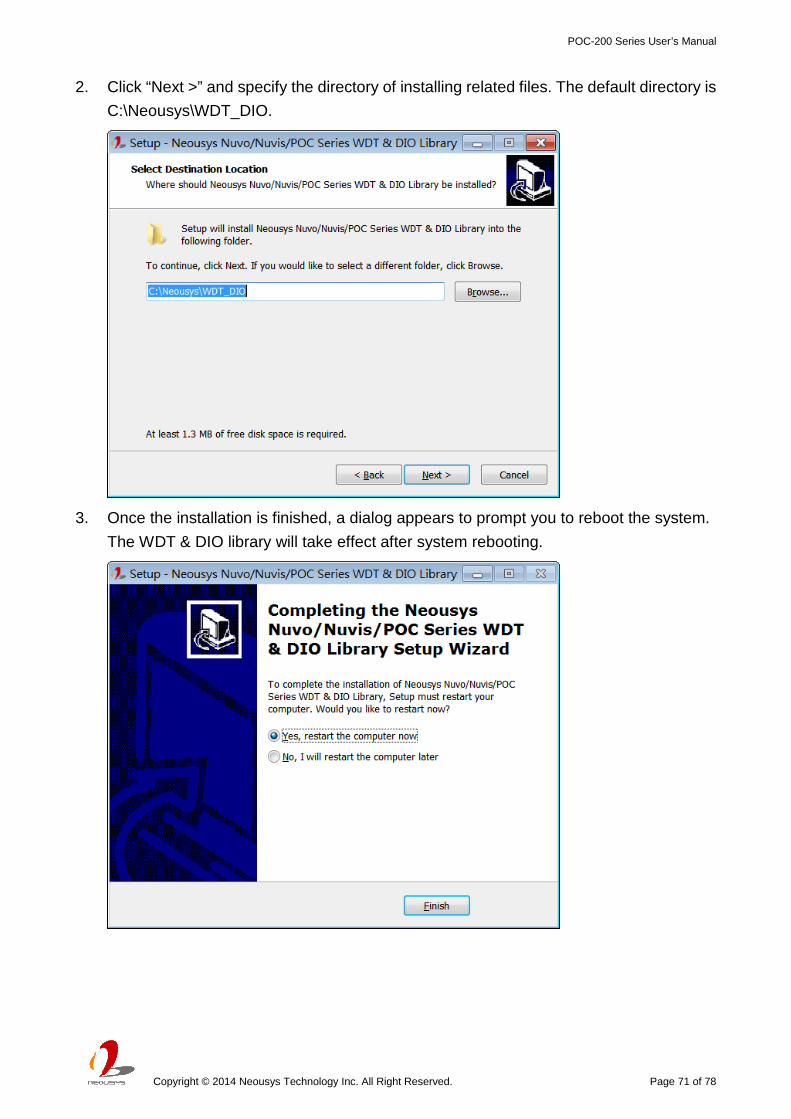
2. Click “Next >” and specify the directory of installing related files. The default directory is
C:\Neousys\WDT_DIO.
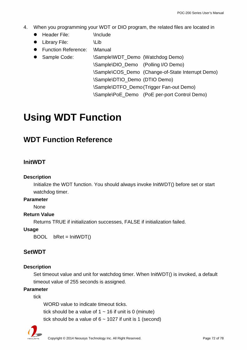
3. Once the installation is finished, a dialog appears to prompt you to reboot the system.
The WDT & DIO library will take effect after system rebooting.
POC-200 Series User’s Manual
Copyright © 2014 Neousys Technology Inc. All Right Reserved. Page 72 of 78
4. When you programming your WDT or DIO program, the related files are located in
Header File: \Include
Library File: \Lib
Function Reference: \Manual
Sample Code: \Sample\WDT_Demo (Watchdog Demo)
\Sample\DIO_Demo (Polling I/O Demo)
\Sample\COS_Demo (Change-of-State Interrupt Demo)
\Sample\DTIO_Demo (DTIO Demo)
\Sample\DTFO_Demo (Trigger Fan-out Demo)
\Sample\PoE_Demo (PoE per-port Control Demo)
Using WDT Function
WDT Function Reference
InitWDT
Description
Initialize the WDT function. You should always invoke InitWDT() before set or start
watchdog timer.
Parameter
None
Return Value
Returns TRUE if initialization successes, FALSE if initialization failed.
Usage
BOOL bRet = InitWDT()
SetWDT
Description
Set timeout value and unit for watchdog timer. When InitWDT() is invoked, a default
timeout value of 255 seconds is assigned.
Parameter tick
WORD value to indicate timeout ticks.
tick should be a value of 1 ~ 16 if unit is 0 (minute)
tick should be a value of 6 ~ 1027 if unit is 1 (second)

POC-200 Series User’s Manual
Copyright © 2014 Neousys Technology Inc. All Right Reserved. Page 73 of 78
unit
BYTE value (0 or 1) to indicate unit of timeout ticks.
0 : unit is minute
1 : unit is second
Return Value
If value of unit is correct (0 or 1), this function returns TRUE, otherwise FALSE.
Usage
WORD tick=255;
BYTE unit=1; //unit is second.
BOOL bRet = SetWDT(tick, unit); //timeout value is 255 seconds
StartWDT
Description
Start countdown of WDT. When WDT is started, the WDT LED indicator starts to blink
in a frequency of 1Hz. If no ResetWDT() or StopWDT is invoked before WDT is
counted to 0, the WDT expires and system resets.
Parameter
None
Return Value
If the timeout value is given in correct format, this function returns TRUE, otherwise
FALSE.
Usage
BOOL bRet = StartWDT()
ResetWDT
Description
Reset the timeout value to the value given by SetWDT(). If no ResetWDT() or
StopWDT is invoked before WDT is counted to 0, the WDT expires and system resets.
Parameter
None
Return Value
Always returns TRUE;
Usage
BOOL bRet = ResetWDT()

POC-200 Series User’s Manual
Copyright © 2014 Neousys Technology Inc. All Right Reserved. Page 74 of 78
StopWDT
Description
Stop the countdown of WDT. When WDT is stopped, the WDT LED indicator stops
blinking.
Parameter
None
Return Value
Always returns TRUE;
Usage
BOOL bRet = StopWDT()
Using DIO Function
Wiring for Isolated DIO (POC-200 Only)
POC-200 supports 4x isolated DI channels and 4x isolated DO channels. The isolated DI
channels are implemented using photo-couplers with internally series-connected 2.4kΩ
resistors. You need to provide a voltage to specify the logic high/low state. The input
voltage for logic high is 5~24V, and the input voltage for logic low is 0~1.5V.
The isolated DO channels are implemented using Power MOSFET + Analog Device
iCoupler® component. The DO channels are configured as NO (normally-open)
configuration. When you turn on system, all DO channels have a deterministic state of logic
0 (circuit disconnected from GND return). When logic 1 is specified, MOSFET is activated

POC-200 Series User’s Manual
Copyright © 2014 Neousys Technology Inc. All Right Reserved. Page 75 of 78
and GND return path is established. The isolated DO on POC-200 supports sinking current
connection. The following diagrams are the suggested wiring for DO:
Pin Definition for Isolated DIO (POC-200 Only)
Pin Definition
Pin# Definition I/O Description
1 ISO_5V O Isolate 5V power supply
2 VDD I DO voltage source input for inductive load
3 DI_0 I Digital input channel 0
4 VDD I DO voltage source input for inductive load
5 DI_1 I Digital input channel 1
6 DO_0 O Digital output channel 0
7 DI_GND - Digital input GND
8 DO_1 O Digital output channel 1
9 DI_2 I Digital input channel 2
10 DO_GND - Digital output GND
11 DI_3 I Digital input channel 3
12 DO_2 O Digital output channel 2
13 DI_GND - Digital input GND
14 DO_3 O Digital output channel 3
15 DI_GND - Digital input signal
16 DO_GND - Digital output GND

POC-200 Series User’s Manual
Copyright © 2014 Neousys Technology Inc. All Right Reserved. Page 76 of 78
Pin Definition for 5V TTL GPIO (POC-210/212/222)
Pin Definition
Pin# Definition I/O Description
1 N.C - No connection
2 N.C - No connection
3 DI_0 I Digital input channel 0
4 N.C. - No connection
5 DI_1 I Digital input channel 1
6 DO_0 O Digital output channel 0
7 N.C. - No connection
8 DO_1 O Digital output channel 1
9 DI_2 I Digital input channel 2
10 D_GND GND Digital GND
11 DI_3 I Digital input channel 3
12 DO_2 O Digital output channel 2
13 N.C. - No connection
14 DO_3 O Digital output channel 3
15 N.C. - No connection
16 D_GND GND Digital GND
DIO Function Reference
InitDIO
Description
Initialize the DIO function. You should always invoke InitDIO() before write/read any
DIO port/channel.
Parameter

POC-200 Series User’s Manual
Copyright © 2014 Neousys Technology Inc. All Right Reserved. Page 77 of 78
None
Return Value
Returns TRUE if initialization successes, FALSE if initialization failed.
Usage
BOOL bRet = InitWDT()
DIReadLine
Description
Read a single channel of isolated digital input.
Parameter ch
BYTE value specifies the DI channel to be read.
ch should be a value of 0 ~ 3.
Return Value
The status (TRUE or FALSE) of the specified DI channel.
Usage
BYTE ch=3; //DI channel #3
BOOL DIChValue = DIReadLine(ch); //read DI channel #3
DIReadPort
Description
Read the entire isolated digital input port (4 channels).
Parameter
None
Return Value
A WORD value indicates the status of DI port (4 DI channels).
Usage
WORD DIPortValue = DIReadPort ();
DOWriteLine
Description
Write a single channel of isolated digital output.
Parameter ch
BYTE value specifies the DO channel to be written.

POC-200 Series User’s Manual
Copyright © 2014 Neousys Technology Inc. All Right Reserved. Page 78 of 78
ch should be a value of 0 ~ 3.
value
BOOL value (TRUE or FALSE) specifies the status of DO channel.
Return Value
None
Usage
BYTE ch=3; //DI channel #3
BOOL DOChValue=TRUE;
DOWriteLine(ch, DOChValue); //write DO channel #3 as TRUE
DOWritePort
Description
Write the entire isolated digital output port (4 channels).
Parameter value
WORD value specifies the status of the DO port.
value should be a value of 0~15.
Return Value
None
Usage
WORD DOPortValue=0x0C; //1100b
DOWritePort(DOPortValue); //write DO port as 1100b