Neotectonic fault analysis .pdf
17
Neotectonic fault analysis by 2D finite element modeling for studying the Himalayan fold-and-thrust belt in Nepal Deepak Chamlagain * , Daigoro Hayashi Department of Physics and Earth Sciences, University of the Ryukyus, Okinawa 903-0213, Japan Received 28 December 2004; accepted 25 October 2005 Abstract This paper examines the neotectonic stress field and faulting in the fold-and-thrust belt of the Nepal Himalaya using the 2D finite element technique, incorporating elastic material behavior under plane strain conditions. Three structural cross-sections (eastern, central and western Nepal), where the Main Himalayan Thrust (MHT) has different geometries, are used for the simulation, because each profile is characterized by different seismicity and neotectonic deformation. A series of numerical models are presented in order to understand the influence of a mid-crustal ramp on the stress field and on neotectonic faulting. Results show that compressive and tensional stress fields are induced to the north and south of the mid-crustal ramp, and consequently normal faults are developed in the thrust sheets moving on the mid-crustal ramp. Since the shear stress accumulation along the northern flat of the MHT is entirely caused by the mid-crustal ramp, this suggests that, as in the past, the MHT will be reactivated in a future large (M w > 8) earthquake. The simulated fault pattern explains the occurrence of several active faults in the Nepal Himalaya. In all models, the distribution of the horizontal r 1 (maximum principal stress) is consistent with the sequence of thrusting observed in the fold-and-thrust belt of the Himalaya. Failure elements around the flat–ramp–flat coincide with the microseismic events in the area, which are believed to release elastic stress partly during interseismic periods. Ó 2007 Published by Elsevier Ltd. Keywords: Numerical simulation; Main Himalayan Thrust; Stress field; Neotectonics; Nepal Himalaya 1. Introduction Thin-skinned fold-and-thrust belts are common in oro- genic belts of all ages. These zones of folding and thrusting along the margin of a mountain belt constitute one of the most widely recognized and best understood deformational features of the earth. Mechanics of fold-and-thrust belts and accretionary wedges have been extensively studied dur- ing the last two decades (Davis et al., 1983; Dahlen, 1990; Lallemand et al., 1994). According to Chapple (1978), the main characteristics of thin-skinned fold-and-thrust belts are: (1) a thin skinned belt, where the limiting horizon is commonly, but not always, close to the crystalline base- ment; (2) a basal layer of detachment or de ´collement, com- posed of weak rock, often shale or evaporite, dipping towards the hinterland; (3) a wedge-shaped region of defor- mation, thicker in the rear where the thrust originates; (4) large amounts of shortening and thickening in the rear of the wedge. This thin-skinned belt is usually composed of a series of thrust sheets with the propagation of deformation from the hinterland towards the foreland, and the development of a surface topography sloping towards the foreland. These typical characteristics can be observed in the Himalayan fold-and-thrust belt, which has developed since ca. 50 Ma as a result of the collision between the Indian and Eurasian plates and the subsequent subduction of India beneath the Himalayas. As the Indian Plate has moved continuously towards the north, the sedimentary prism deposited at the northern tip of the Indian Plate has been detached from the underlying basement to form large south vergent thrust sheets, which are bounded by intra-crustal thrusts (Fig. 1). 1367-9120/$ - see front matter Ó 2007 Published by Elsevier Ltd. doi:10.1016/j.jseaes.2005.10.016 * Corresponding author. Tel.: + 81 906 862 4192; fax: + 81 98 895 8552. E-mail address: [email protected] (D. Chamlagain). www.elsevier.com/locate/jaes Journal of Asian Earth Sciences 29 (2007) 473–489
-
Upload
sushil-dhungana -
Category
Documents
-
view
54 -
download
0
Transcript of Neotectonic fault analysis .pdf

www.elsevier.com/locate/jaes
Journal of Asian Earth Sciences 29 (2007) 473–489
Neotectonic fault analysis by 2D finite element modelingfor studying the Himalayan fold-and-thrust belt in Nepal
Deepak Chamlagain *, Daigoro Hayashi
Department of Physics and Earth Sciences, University of the Ryukyus, Okinawa 903-0213, Japan
Received 28 December 2004; accepted 25 October 2005
Abstract
This paper examines the neotectonic stress field and faulting in the fold-and-thrust belt of the Nepal Himalaya using the 2D finiteelement technique, incorporating elastic material behavior under plane strain conditions. Three structural cross-sections (eastern, centraland western Nepal), where the Main Himalayan Thrust (MHT) has different geometries, are used for the simulation, because each profileis characterized by different seismicity and neotectonic deformation. A series of numerical models are presented in order to understandthe influence of a mid-crustal ramp on the stress field and on neotectonic faulting. Results show that compressive and tensional stressfields are induced to the north and south of the mid-crustal ramp, and consequently normal faults are developed in the thrust sheetsmoving on the mid-crustal ramp. Since the shear stress accumulation along the northern flat of the MHT is entirely caused by themid-crustal ramp, this suggests that, as in the past, the MHT will be reactivated in a future large (Mw > 8) earthquake. The simulatedfault pattern explains the occurrence of several active faults in the Nepal Himalaya. In all models, the distribution of the horizontal r1
(maximum principal stress) is consistent with the sequence of thrusting observed in the fold-and-thrust belt of the Himalaya. Failureelements around the flat–ramp–flat coincide with the microseismic events in the area, which are believed to release elastic stress partlyduring interseismic periods.� 2007 Published by Elsevier Ltd.
Keywords: Numerical simulation; Main Himalayan Thrust; Stress field; Neotectonics; Nepal Himalaya
1. Introduction
Thin-skinned fold-and-thrust belts are common in oro-genic belts of all ages. These zones of folding and thrustingalong the margin of a mountain belt constitute one of themost widely recognized and best understood deformationalfeatures of the earth. Mechanics of fold-and-thrust beltsand accretionary wedges have been extensively studied dur-ing the last two decades (Davis et al., 1983; Dahlen, 1990;Lallemand et al., 1994). According to Chapple (1978), themain characteristics of thin-skinned fold-and-thrust beltsare: (1) a thin skinned belt, where the limiting horizon iscommonly, but not always, close to the crystalline base-ment; (2) a basal layer of detachment or decollement, com-
1367-9120/$ - see front matter � 2007 Published by Elsevier Ltd.
doi:10.1016/j.jseaes.2005.10.016
* Corresponding author. Tel.: + 81 906 862 4192; fax: + 81 98 8958552.
E-mail address: [email protected] (D. Chamlagain).
posed of weak rock, often shale or evaporite, dippingtowards the hinterland; (3) a wedge-shaped region of defor-mation, thicker in the rear where the thrust originates; (4)large amounts of shortening and thickening in the rear ofthe wedge.
This thin-skinned belt is usually composed of a series ofthrust sheets with the propagation of deformation from thehinterland towards the foreland, and the development of asurface topography sloping towards the foreland. Thesetypical characteristics can be observed in the Himalayanfold-and-thrust belt, which has developed since ca. 50 Maas a result of the collision between the Indian and Eurasianplates and the subsequent subduction of India beneath theHimalayas. As the Indian Plate has moved continuouslytowards the north, the sedimentary prism deposited atthe northern tip of the Indian Plate has been detached fromthe underlying basement to form large south vergent thrustsheets, which are bounded by intra-crustal thrusts (Fig. 1).

Fig. 1. Geological map of Nepal (modified after Upreti and Le Fort (1999)). LH, Lesser Himalaya; HH, Higher Himalaya; TTS, Tibetan-Tethys sequence;MBT, Main Boundary Thrust; MCT, Main Central Thrust; MFT, Main Frontal Thrust; STDS, South Tibetan Detachment System. A–A 0, B–B 0, and C–C 0: tentative location of the cross-section lines.
474 D. Chamlagain, D. Hayashi / Journal of Asian Earth Sciences 29 (2007) 473–489
From north to south these are the Main Central Thrust(MCT), the Main Boundary Thrust (MBT) and the MainFrontal Thrust (MFT).
Quantitative estimation of the tectonic stress field inthe fold-and-thrust belt, both on regional and local scales,is an important constraint for understanding faulting andthe resulting geodynamics. In this regard, numerical mod-eling (Willet et al., 1993; Beaumont et al., 1994; Sassi andFaure, 1997; Mikhailov et al., 2002; Chamlagain andHayashi, 2004) has been applied extensively to explorethe style of deformation and the development of thrustsystems during the evolution of the fold-and-thrust belt.Compared to other techniques, numerical techniquesallow the modeling of the structure and the deformationat full scale and to compute stress and strain values overa long time period, using various constitutive laws. How-ever, computations are lengthy and require knowledge ofthe rheological parameters, which are usually poorly con-strained. Makel and Walters (1993) applied finite elementmodeling to the study of the mechanics of thrust forma-tion in rectangular and wedge-shaped basins overlying aweak substratum. Using an elastic–plastic law with strainsoftening characteristics, they obtained a thrust in therectangular block, and a system of a thrusts and a back-thrusts in the tapered wedge, for a relatively small amount
of shortening (tens of meters for a 20 km block). Vanbra-bant et al. (1999) proposed numerical models for the Vari-scan fold-and-thrust belt of Belgium to obtain an insightinto its evolution. They found that ramps have a signifi-cant influence on the development of the belt. For theHimalayan region, Wang and Shi (1982) simulated a1500 km long section from the Gangetic Plain in thesouth to Kunlun in the north, using a 2D finite elementmethod under plane strain conditions. Using nonlinearviscous rheology, they predicted a thickening rate(2 mm yr�1) for Tibet, with shortening partitioned acrossthe entire orogen. They proposed that the Himalaya isdynamically supported. Singh et al. (1990) also modeleda cross-section extending from the Ganga Basin to theTibetan Plateau, aiming to simulate earthquake activityusing force rather than displacement boundary condi-tions. They suggested that the stress concentration indi-cated by frequent shallow earthquakes in the Himalayanand Tibetan regions is due to force acting from the northside, which is associated with a convection currentbeneath the Tibetan Plateau. This idea is somewhat con-troversial in the present state of knowledge of earthquakemechanisms in the Himalaya. Recently, Berger et al.(2004) simulated the interseismic deformations in NepalHimalaya. They pointed out that the brittle–ductile

D. Chamlagain, D. Hayashi / Journal of Asian Earth Sciences 29 (2007) 473–489 475
transition and geometry of the Main Himalayan Thrust(MHT) are the main factors that influence present-daydeformation in the Nepal Himalaya.
Neotectonic studies (Nakata, 1989; Nakata et al., 1990;Mugnier et al., 1994) in the Himalaya have revealed vari-ous recent movements (e.g. normal faulting, strike–slipfaulting and thrust faulting) along active faults close tothe MBT and within the Lesser Himalaya. These move-ments have been attributed to recent changes in the tecton-ic regime in the Himalaya. It has also been found that theapparent slip of normal faults close to the intra-crustalthrusts is down to the north, indicating extension. This isnot consistent with seismic events of a compressive nature.In this paper, we attempt to clarify the cause of normalfaulting in such compressional regimes by applying a 2Dplane strain, elastic finite element modeling technique.We further explore the effect of a mid-crustal ramp onthe neotectonic stress field in the Nepal Himalaya. Finally,we will compare overall results of the modeling with therecord of microseismicity and active faulting in the regionto gain a better understanding of the neotectonics of theNepal Himalaya.
2. Tectonic setting of the Himalayan fold-and-thrust belt
As we mentioned in the previous section, the regionalstructural geology of the fold-and-thrust belt of NepalHimalaya to the south of South Tibetan Detachment System(STDS) is controlled mainly by three major thrust systems,e.g. from north to south the MCT, MBT and MFT(Fig. 1). These thrust faults, with a N–S transport direction,are generally inferred to be splay thrusts of the MHT, whichmarks the underthrusting of the Indian Plate. Most of thecross-sections across the Himalaya suggest a mid-crustalramp beneath a large antiformal structure of the LesserHimalaya, and to the north of a synformal structure (Schel-ling and Arita, 1991; Srivastava and Mitra, 1994; Decelleset al., 2001). Geological, geophysical and structural dataindicate that there are lateral variations in the geometry ofthe MHT (e.g. Zhao et al., 1993; Pandey et al., 1995, 1999),but direct knowledge of the geometry of the MHT is sparseand therefore the validity of the profiles is still in debate.
The MFT system consists of two or three thrust sheetscomposed entirely of Siwalik rocks; from bottom to topmudstone, multi-storied sandstone and conglomerate.These sedimentary foreland basin deposits provide a recordof the final stages of the Himalayan upheaval since�14 Ma, and also record the most recent tectonic eventsin the evolution of the Himalaya. In general, this beltexhibits a fault-bend fold structure throughout the NepalHimalaya. Minor structures include normal faults withcentimeter to several meters of displacement. The northern-most thrust sheet of the MFT is truncated by the LesserHimalayan sequence and overlain by unmetamorphosedto weakly metamorphosed rocks of the Lesser Himalaya,where the Lesser Himalayan rock package is thrust overthe Siwalik Group along the MBT. In western Nepal, crys-
talline thrust sheets are frequently observed within theLesser Himalaya, e.g. Dadeldhura crystalline thrust sheet(Hayashi et al., 1984). The Lesser Himalayan zone general-ly forms a duplex above the mid-crustal ramp (Schellingand Arita, 1991; Srivastava and Mitra, 1994; Decelleset al., 2001). The MCT system overlies the Lesser Himala-yan MBT system and was formed ca. 24 Ma. This MCTsystem consists of high-grade rocks, e.g. kyanite–sillimanitegneiss, schist and quartzite, and is characterized mostly byductile deformation.
3. Active faults in the Nepal Himalaya
The Himalaya is one of the most neotectonically activemountain belts in the world. The active faults, in andaround this belt are direct indicators of recent crustalmovement due to the collision between the Indian and Eur-asian plates. In this section, therefore, active faults andtheir tectonic significance are reviewed, in order to clarifythe neotectonics of the Himalayan fold-and-thrust belt.In the Nepal Himalaya (Fig. 2) active faults, are distributedalong the major tectonic elements, as well as along oldergeological faults, and are classified into four groups (Nak-ata, 1982): the Main Central Active Fault system, activefaults in Lower Himalayas, the Main Boundary ActiveFault system and active faults along the Himalayan Fron-tal Fault (equivalent to MFT). Among these, active faultsalong the MBT and MFT are most active, and have thepotential to produce large earthquakes in the future (Laveand Avouac, 2000; Chamlagain et al., 2000).
The Himalayan front in eastern Nepal is characterizedby landforms produced by active faulting, along both theMBT and MFT. Near Timai Khola in eastern Nepal,active faults trending NW–SE along the MBT merge withthe active faults striking E–W along the MFT and extend-ing farther south into the Gangetic plain (Fig. 2). Theseactive faults exhibit down-throw towards the north. In cen-tral Nepal, traces of active faults are continuous, especiallyin Hetaunda and south of the Kathmandu valley aroundthe Bagmati River (Chamlagain et al., 2000; Kumaharaet al., 2001). Active faults along the MFT also show north-ward downthrows. Active faulting along the MBT is repre-sented by Arung Khola Fault, the Hetaunda Fault andUdaipur Fault in the east. The traces of these faults arecontinuous and the north-facing scarplets suggest that theyindicate northward dipping fault planes. In western Nepal,active faults along the MBT appear as single, straight, con-tinuous, fault traces at many places. A common topo-graphic feature is a pressure ridge and the vertical slipalong the fault is apparently down to the north. Activefaults along the MBT, though considered to be basicallyreverse faults, do not always show a reverse displacement(Nakata et al., 1984), that is active faults close to theMBT are of normal type (Mugnier et al., 1994). Alongthe MFT, active faults appear to be continuous, as in wes-tern Nepal. In the Nepal Himalaya along the Himalayanfront, the characteristics of active faults vary from place

Fig. 2. Active faults in and around Nepal Himalaya. Thick lines without tick marks show newly found active faults. Arrow indicates the direction of strikeslip. Down-thrown side is shown by tick marks (after Nakata and Kumahara (2002)). A–A0, B–B 0 and C–C 0: location of the cross-section lines.
476 D. Chamlagain, D. Hayashi / Journal of Asian Earth Sciences 29 (2007) 473–489
to place, and this is attributed to the difference in the vol-ume of the Siwaliks in different sections of the collisionzone. Nakata et al. (1990) obtained the stress field by usingthe strike and the type of active faults in the collision zone.The stress trajectories show a disturbed pattern near themargin of the Eurasian Plate and are not everywhere con-sistent with the relative motions of the Indian and Eurasianplates. For the central Himalaya, at least, the stress fieldshows a horizontal compressive stress consistent with theplate motion. On the other hand, geomorphic analysisshows that the MFT has absorbed, on average,21±1.5 mm yr�1 of N–S shortening south of the Himalayaduring Holocene period (Lave and Avouac, 2000). Micro-seismicity and geodetic data suggest interseismic stressaccumulation beneath the Higher Himalayan front, whichcould in future induce a devastating earthquake(Mw > 8). Earthquakes along the MHT can break up tothe near surface at the front of the Himalayan foothillsand could result in incremental activation of the MFT.
4. Microseismicity
Present-day deformation in the Himalayan fold-and-thrust belt is characterized by large earthquakes (e.g.1905 Kangra earthquake; 1934 Bihar–Nepal earthquake)of which the magnitude in Mw is ca. 8. These earthquakesappear to be due to ruptures along the MHT. During theseevents segments of the MHT, 200–300 km along strike and60–100 km down-dip, are affected by coseismic displace-ments. The locations of the ruptured areas indicate that
there is a gap along the mountain range between the Kan-gra (1905) and Bihar–Nepal earthquakes (1934) (Fig. 3). Inthe Himalayan fold-and-thrust belt, focal mechanism dataindicates shallow (10–20 km) earthquakes beneath theLesser Himalaya, demonstrating the activation of thrustplanes gently dipping to the north (Ni and Barazangi,1984). Detailed analysis of the Uttarkashi earthquake (Cot-ton et al., 1996) in the west of Nepal indicates that thisevent was initiated to the south of the Higher Himalayanfront at 12±3 km depth, corresponding to the southwardpropagation of a rupture along this segment of the MHT.
Intense microseismicity and moderate earthquake eventsthroughout the Nepal Himalaya cluster along the foothillsof the Higher Himalaya (Pandey et al., 1995), forming anE–W trending zone, as shown in Fig. 3. In western Nepal,this cluster lies between 80.5�E and 82.5�E, whereas in cen-tral Nepal it lies between longitudes 82.5�E and 86.5�E.The eastern Nepal cluster is characterized by higher levelof events between 86.5�E and 88.5�E. The projection ofmicroseismic events into the structural cross-section showsa noticeable change in the shape and location of clustersbetween central and western Nepal (Fig. 4). In centralNepal, the cluster has a rounded form and is located inthe vicinity of the flat-ramp transition of the MHT. Thecluster in western Nepal shows an elongate form and isnearly horizontal. These clusters reflect stress accumulationin the interseimic period, during which the decollementbeneath the Higher Himlaya probably remained lockedwith the mid-crustal ramp acting as a geometrical asperity(Pandey et al., 1995).

Fig. 3. Seismicity in the Himalayas of Nepal (after Jouanne et al. (2004)). Intense microseismicity (monitored between 1985 and 1998) shown by gray tintand small circles, tend to cluster south of the Higher Himalayas (Pandey et al. (1999)) at mid-crustal level. Stars represent medium size earthquakes. A–A 0,B–B 0 and C–C 0: location of the cross-section lines.
a
b
Fig. 4. Density distribution of epicenters (a) central Nepal (b) western Nepal (modified after Pandey et al. (1999)).
D. Chamlagain, D. Hayashi / Journal of Asian Earth Sciences 29 (2007) 473–489 477
5. Simulation of stress and faulting
The neotectonic stress distribution and the resultingfaults can be computed using 2D finite element method
adopting a simple modeling approach. In this study, weadopt elastic rheology under plane strain conditions. Grav-itational force is incorporated in all models. We considerthat the MHT is a weak zone, so that it is allocated a
a
b
c
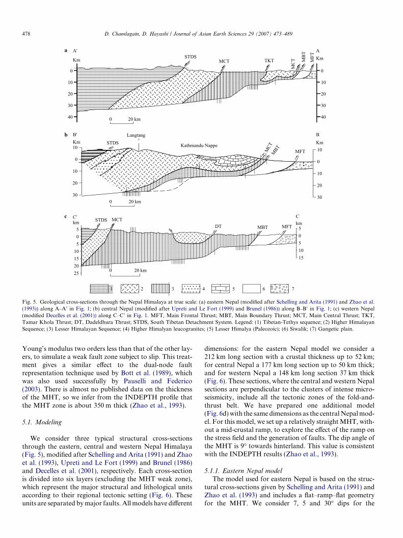
Fig. 5. Geological cross-sections through the Nepal Himalaya at true scale: (a) eastern Nepal (modified after Schelling and Arita (1991) and Zhao et al.(1993)) along A–A0 in Fig. 1; (b) central Nepal (modified after Upreti and Le Fort (1999) and Brunel (1986)) along B–B 0 in Fig. 1; (c) western Nepal(modified Decelles et al. (2001)) along C–C 0 in Fig. 1. MFT, Main Frontal Thrust; MBT, Main Boundary Thrust; MCT, Main Central Thrust; TKT,Tamar Khola Thrust; DT, Dadeldhura Thrust; STDS, South Tibetan Detachment System. Legend: (1) Tibetan-Tethys sequence; (2) Higher HimalayanSequence; (3) Lesser Himalayan Sequence; (4) Higher Himalyan leucogranites; (5) Lesser Himalya (Paleozoic); (6) Siwalik; (7) Gangetic plain.
478 D. Chamlagain, D. Hayashi / Journal of Asian Earth Sciences 29 (2007) 473–489
Young’s modulus two orders less than that of the other lay-ers, to simulate a weak fault zone subject to slip. This treat-ment gives a similar effect to the dual-node faultrepresentation technique used by Bott et al. (1989), whichwas also used successfully by Pauselli and Federico(2003). There is almost no published data on the thicknessof the MHT, so we infer from the INDEPTH profile thatthe MHT zone is about 350 m thick (Zhao et al., 1993).
5.1. Modeling
We consider three typical structural cross-sectionsthrough the eastern, central and western Nepal Himalaya(Fig. 5), modified after Schelling and Arita (1991) and Zhaoet al. (1993), Upreti and Le Fort (1999) and Brunel (1986)and Decelles et al. (2001), respectively. Each cross-sectionis divided into six layers (excluding the MHT weak zone),which represent the major structural and lithological unitsaccording to their regional tectonic setting (Fig. 6). Theseunits are separated by major faults. All models have different
dimensions: for the eastern Nepal model we consider a212 km long section with a crustal thickness up to 52 km;for central Nepal a 177 km long section up to 50 km thick;and for western Nepal a 148 km long section 37 km thick(Fig. 6). These sections, where the central and western Nepalsections are perpendicular to the clusters of intense micro-seismicity, include all the tectonic zones of the fold-and-thrust belt. We have prepared one additional model(Fig. 6d) with the same dimensions as the central Nepal mod-el. For this model, we set up a relatively straight MHT, with-out a mid-crustal ramp, to explore the effect of the ramp onthe stress field and the generation of faults. The dip angle ofthe MHT is 9� towards hinterland. This value is consistentwith the INDEPTH results (Zhao et al., 1993).
5.1.1. Eastern Nepal model
The model used for eastern Nepal is based on the struc-tural cross-sections given by Schelling and Arita (1991) andZhao et al. (1993) and includes a flat–ramp–flat geometryfor the MHT. We consider 7, 5 and 30� dips for the

a
b
c
d
Fig. 6. Geometry and boundary conditions for (a) eastern Nepal model (b) central Nepal model (c) western Nepal model (d) model without ramp. TTS,Tibetan-Tethys sequence; HHS, Higher Himalayan sequence; LHS, Lesser Himalaya–sequence; SW, Siwalik; GP, Gangetic Plain; IS, Indian Shield;STDS, South Tibetan Detachment System; MCT, Main Central Thrust; TKT, Tamar Khola Thrust; DT, Dadeldhura Thrust; MBT, Main BoundaryThrust; MFT, Main Frontal Thrust; MHT, Main Himalayan Thrust.
D. Chamlagain, D. Hayashi / Journal of Asian Earth Sciences 29 (2007) 473–489 479
northern flat, the southern flat and the ramp, respectively,as proposed by Berger et al. (2004) (Fig. 6a). These data areconsistent with INDEPTH seismic profile given by Zhaoet al. (1993).
5.1.2. Central Nepal modelThe central Nepal model is based on the cross-section
after Upreti and Le Fort (1999) and the geometry of the
MHT is based on Brunel’s (1986) cross-section. This geom-etry has a dip of 5.5� for the northern flat, 5� for the south-ern flat and 30� for the mid-crustal ramp (Berger et al.,2004) (Fig. 6b).
5.1.3. Western Nepal modelFor the western Nepal model, we have taken the struc-
tural geometry proposed by Decelles et al. (2001). They

480 D. Chamlagain, D. Hayashi / Journal of Asian Earth Sciences 29 (2007) 473–489
propose only a single mid-crustal ramp along the MHT inwestern Nepal Himalaya. For computation, we considerthe dip of the northern flat, the southern flat and themid-crustal ramp to be 6, 5 and 30�, respectively(Fig. 6c), based on the dip angles proposed by Bergeret al. (2004).
5.2. Boundary conditions
Selection of the boundary conditions is one of the keysteps in simulating tectonic processes. In order to matchthe natural situation, we impose reasonable boundary con-ditions to represent present-day plate kinematics in theHimalayan fold-and-thrust belt. In all models, the uppersurface is free. Since the basal boundary of all models isinclined, the convergent displacement is resolved into bothx and y directions, and imposed accordingly. The nodesalong the left boundary of each model can only move ver-tically, whereas from the right side of the models, weimpose a convergent displacement at incremental steps,which gradually decrease toward left side of the model.The lowermost node of the left hand side of the model isfixed in each model (Fig. 6). We apply a uniform conver-gence displacement of up to 500 m, at a rate of 21 mm yr�1
Fig. 7. Rock laye
for eastern Nepal and 20 mm yr�1 for central and westernNepal. These convergence rates are consistent with GPSmeasurements (Jouanne et al., 2004) and Quaternary dis-placements (Lave and Avouac, 2000) along the MFT inthe Nepal Himalaya.
5.3. Rock layer properties
As mentioned above, for the sake of simplicity in calcu-lation, all models are divided into six layers taking accountof the tectonostratigraphy. To calculate the stress field andthe resulting deformation in a specific area of the litho-sphere, it is essential to know the mechanical propertiesin that area. In our FEM elastic calculation, we need twoindependent constants: Young’s modulus (E), and the Pois-son ratio (m). These parameters are poorly constrained forthe Himalayan rocks. Since the density of the major rocksof the each tectonic rock packages is known, we obtain P-wave seismic velocity (Vp) for each rock layer from the dia-gram proposed by Barton (1986) and compare them withthe published velocity model (Pandey et al., 1995) for theNepal Himalaya. Since we know the density (q), Vp andm, the dynamic Young’s modulus for each layer can be cal-culated using equation:
r properties.

D. Chamlagain, D. Hayashi / Journal of Asian Earth Sciences 29 (2007) 473–489 481
E ¼ qV 2p
ð1þ mÞð1� 2mÞð1� mÞ ð1Þ
Assuming that the static Young’s modulus is 80% of thedynamic Young’s modulus, for calculation we use the staticYoung’s modulus for each tectonic rock unit as shown inFig. 7. These are consistent with the values for continentalcrustal rocks determined in the laboratory and with otherpublished data (Sydney and Clark, 1966).
6. Results
Stress state is one of the good proxies for understandingdeformation in the crust and depends entirely on the tec-tonic boundary conditions and the rheology of the rocklayers. These constraints also maintain for the Himalayanfold-and-thrust belt, where the state of stress is governedby geometry, tectonic boundary conditions and the conver-gence rate of the Indian Plate. The MHT is the main struc-tural discontinuity in the Himalaya, its geometry has asignificant influence on the changes in the stress field andcontrols the stress state and the associated deformation.Since the convergence rate of the Indian Plate has beendecreasing (Patrait and Achache, 1984) since 40 Ma, thestress field will show consequent changes. Therefore, it isnecessary to explore the changes in stress regime with eachnew tectonic phase, taking into account the changes in the
52 k
m0
0
a STDS
0
52 k
m0
b STDS
0
Fig. 8. Stress distribution in the eastern Nepal model: (a) at 50 m convergperpendicular lines represents r1 (long lines) r3 (short lines) in the stress field. TFig. 6.
geometry of the structure. In the context of neotectonics inthe Himalaya, in the following sections, we will discuss thesimulated stress field and the faulting separately, to appre-ciate differences in each section.
6.1. Results of stress field
We simulate the pattern of the stress field as a functionof the model geometry and rock layer properties under var-ious convergent displacements. The simulated stress fieldsfor eastern Nepal, central Nepal and western Nepal areshown in Figs. 8–10, respectively. In general, all modelsshow two characteristic regimes of the stress field underlow convergent displacement (50 m): a compressive stressfield to the north, and a tensional stress field to the southof the mid-crustal ramp (Figs. 8a, 9a and 10a). The orien-tation of the stress field is also changed according to thestructural characteristics of the model. To the north ofthe mid-crustal ramp, the stress field shows rotation wherer1 is deflected from its vertical position and finally becomeshorizontal in the upper part of the model. This stress fieldhas the potential to give rise to thrust faulting in a conver-gent tectonic environment. In contrast, to the south of themid-crustal ramp, r1 is oriented vertically, together withthe tensional component of the minimum principal stress(r3). In this stress field extensional tectonics will develop.With increasing convergent displacement (500 m) the stress
212 km
500 MPa
50 m
MFT
MBT
MCT
MCT
TKT
212 km
500 m
MFT
MBT
MCT
MCT
TKT
ent displacement; (b) at 500 m convergent displacement. Every pair ofhe tensional stress field is shown by open circles. Abbreviations are same as

a
b
Fig. 9. Stress distribution in the central Nepal model: (a) at 50 m convergent displacement; (b) at 500 m convergent displacement. Every pair ofperpendicular lines represents r1 (long lines) r3 (short lines) in the stress field. The tensional stress field is shown by open circles. Abbreviations are same asFig. 6.
482 D. Chamlagain, D. Hayashi / Journal of Asian Earth Sciences 29 (2007) 473–489
field changes into a compressive state (Figs. 8b, 9b and10b) because the stress state is a function of the convergentdisplacement in such a tectonic setting. Further, the mid-crustal ramp acts as a geometrical asperity, which conse-quently changes the magnitude of the stress and the orien-tation of the stress field. The central and western Nepalmodels, however, still show a tensional stress field to thesouth of the mid-crustal ramp. In the following sections,we will describe separately the specific features of the stressfield in each model.
6.1.1. Eastern Nepal
The tectonic setting and geometry of the eastern Nepalmodel is different from that of the other models. The High-er Himalayan sequence has been thrust over the LesserHimalayan sequence along the MCT and a few kilometersto the north a mid-crustal ramp is located beneath thissequence. These differences have induced a distinct stressfield. A tensional stress field is prevalent to the south ofthe mid-crustal ramp (Fig. 8a). Increased convergent dis-placement has, however, induced a compressive stress field.In the Indian Shield, the orientation of r1 remainsunchanged as we increase the convergence displacement(Fig. 8b). Shear stress shows a non-uniform distribution(Fig. 11a). The contour of the lowest value (50 MPa) ofshear stress extends from north to south at shallow depth.
Below this, the shear stress increases gradually, reaching300 MPa around the northern flat of the MHT.
6.1.2. Central Nepal
The structure and geometry of the central Nepal section,where the Kathmandu Nappe is emplaced above the mid-crustal ramp, is different from the other models. We assumethat the rock unit in the core is mechanically equivalent tothe Tibetan Tethys sequence and is characterized by a ten-sional stress field (Fig. 9a). A few elements in the Siwalikalso show a tensional stress field. With increasing conver-gent displacement the stress field changes into compressivestate (Fig. 9b). The shear stress shows its lowest value(50 MPa) in two regions: first to the south of the mid-crust-al ramp and second at the shallow depth to the north ofmid-crustal ramp, where more or less hydrostatic condi-tions prevail. The northern flat of the MHT shows themaximum (350 MPa) shear stress buildup (Fig. 11b).
6.1.3. Western Nepal
In western Nepal, we consider a single mid-crustal ramplocated beneath the Dadeldhura crystalline thrust sheet,which is equivalent to the Higher Himalayan sequence.Comparatively, this model shows more elements with atensional stress field, mainly distributed in the LesserHimalayan sequence and in the Siwalik (Fig. 10a). To the

a
b
Fig. 10. Stress distribution in the western Nepal model: (a) at 50 m convergent displacement; (b) at 500 m convergent displacement. Every pair ofperpendicular lines represents r1 (long lines) r3 (short lines) in the stress field. The tensional stress field is shown by open circles. Abbreviations are same asFig. 6.
D. Chamlagain, D. Hayashi / Journal of Asian Earth Sciences 29 (2007) 473–489 483
south of the mid-crustal ramp, the Indian Shield differentlyshows a compressive state of stress where stress trajectoriesare rotated, indicating the strong influence of the mid-crustal ramp on the stress state (Fig. 10b). Similarly, tothe north of the mid-crustal ramp the r1 axis rotatesanti-clockwise and finally becomes horizontal. The westernNepal model shows a different shear stress distribution pat-tern to that of eastern and central Nepal. The contours ofthe minimum shear stress (50 MPa) are sparsely distributed(Fig. 11c). The magnitude of shear stress reaches up to250 MPa along the northern flat, less than that in the east-ern and central Nepal Himalaya.
6.1.4. Model without mid-crustal ramp
We have also simulated another central Nepal model,without a ramp along the MHT to understand the effectof the ramp on the neotectonic stress field and the devel-opment of faults. This model shows very few elementswith a tensional stress field (Fig. 12a). Furthermore, thenorthern flat shows a smaller magnitude of shear stress(300 MPa) than the model with ramp geometry, wherein a small area of the model the magnitude of the shearstress reaches 350 MPa (Fig. 11d). Although the differencein shear stress (50 MPa), and its extent is smaller, theoverall features of the simulated stress field are differentfrom those of the same model with a ramp geometry,indicating positively the influence of the mid-crustal rampon the stress field.
6.2. Results of fault distribution
Using well-known Mohr–Coulomb failure criterion, wehave computed several failure elements in each section forthe eastern, central and western Nepal Himalaya, shownin Figs. 13–15, respectively. In general, all sections showa similar pattern of fault development. Only representa-tive models are described here. Under convergent dis-placement of 150 m, we observe mostly thrust faults tothe north of the mid-crustal ramp, whereas normal faultsare extensively developed to the south (Figs. 13a, 14a and15a). Thrust faults are developed mostly in the LesserHimalayan and the Higher Himalayan sequences of cen-tral and western Nepal Himalaya. Their numbers, howev-er, increase from the eastern to western Nepal Himalaya.Since south of the mid-crustal ramp the stress field is ten-sional, normal faults are obtained accordingly, distributedmostly in the Lesser Himalayan sequence and in the Siwa-liks in eastern and western Nepal. In addition, in centralNepal we also observe normal faults in the core of Kath-mandu Nappe (Fig. 14a). Beside these, a cluster of failureelements is observed around the mid-crustal ramp in cen-tral Nepal and along the northern flat of the MHT inwestern Nepal. However, in the eastern Nepal model wecould not observe such a cluster of failure elements. Withincreasing convergent displacement (500 m), the numberof failure elements increases to the north of mid-crustalramp, but decreases to the south (Figs. 13b, 14b and
a
b
c
d
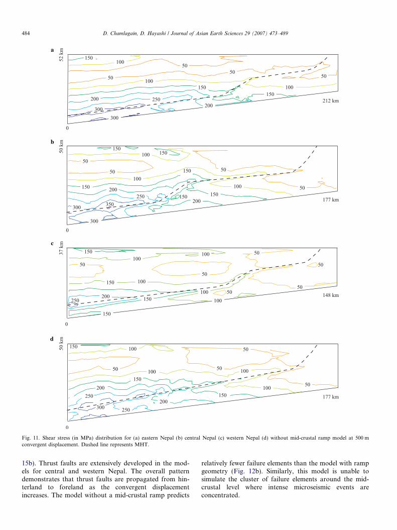
Fig. 11. Shear stress (in MPa) distribution for (a) eastern Nepal (b) central Nepal (c) western Nepal (d) without mid-crustal ramp model at 500 mconvergent displacement. Dashed line represents MHT.
484 D. Chamlagain, D. Hayashi / Journal of Asian Earth Sciences 29 (2007) 473–489
15b). Thrust faults are extensively developed in the mod-els for central and western Nepal. The overall patterndemonstrates that thrust faults are propagated from hin-terland to foreland as the convergent displacementincreases. The model without a mid-crustal ramp predicts
relatively fewer failure elements than the model with rampgeometry (Fig. 12b). Similarly, this model is unable tosimulate the cluster of failure elements around the mid-crustal level where intense microseismic events areconcentrated.

a
b
Fig. 12. Model without mid-crustal ramp: (a) stress distribution at 50 m convergent displacement; (b) failure elements at 150 m convergent displacement.Every pair of perpendicular lines represents r1 (long lines) r3 (short lines) both in the stress field and failure elements. The tensional stress field is shown byopen circles. Abbreviations are same as Fig. 6.
D. Chamlagain, D. Hayashi / Journal of Asian Earth Sciences 29 (2007) 473–489 485
7. Discussion
7.1. Modeling assumptions
We have presented a series of 2D finite element modelsto gain a better understanding of the neotectonics of thefold-and-thrust belt of the Nepal Himalaya using three dif-ferent structural cross-sections, which are representative ofthe present-day geometry of the Nepal Himalaya. We haveimposed reasonable boundary conditions consistent withthe present-day plate kinematics of the region. Further, aconvergence displacement has been applied, instead ofthe forces or stress, because latter are difficult to assess,whereas the relative velocity of the Indian Plate withrespect to Eurasian Plate for the Nepal Himalaya is wellconstrained. All models assume that each layer represent-ing the tectonic rock units is a homogeneous and isotropicbody. We have also assumed that the crust behaves elasti-cally by which we can simulate the faulting.
7.2. Neotectonic stress field in Nepal Himalaya
Numerical models, presented herein to explore the neo-tectonic stress field and faults, have been simplified withrespect to structure of the Himalaya and associated platekinematics. Nevertheless, they still provide a rigorous basisfor interpreting the neotectonic stress distribution in rela-
tionship to the major structural features, active faults, seis-micity and the kinematics of the collison-subduction zone.Nakata et al. (1990) deduced the N–S direction of the max-imum horizontal principal stress (rHmax) for eastern andcentral sectors of the Himalaya, using the type and thestrike of active faults. They further argued that thedirection of rHmax is shifted according to a change in thedirection of relative plate motion. We have set up the mod-el section plane so that the strike (approximately NE–SW)coincides with rHmax.
Our simulated models fall into two categories: a modelwith ramp geometry along the MHT, and a model withoutramp geometry. Models with a mid-crustal ramp show twotypes of stress field at lower convergent displacement: acompressive stress field north of the mid-crustal ramp,and a tensional stress to the south of the mid-crustal ramp.These states of stress are also maintained with a higherconvergent displacement (500 m) in the eastern and westernNepal models. In contrast, a model without a mid-crustalramp shows a more or less compressive stress field in allregions, which may not be consistent with observations inthe tectonically active fold-and-thrust belt, where neotec-tonics is characterized by active normal faulting in a con-vergent tectonic setting. Furthermore, the r1 axisgradually changes from an inclined to a horizontal positionto the north of the mid-crustal ramp. All these results clear-ly indicate the influence of the mid-crustal ramp on the

52 k
m0
0 212 km
500 MPa
150 m
MFT
MBT
MCT
MCT
STDS
TKT
52 k
m0
0 212 km
500 m
MFT
MBT
MCT
MCT
STDS
TKT
a
b
Fig. 13. Failure elements in the eastern Nepal model: (a) at 150 m convergent displacement; (b) at 500 m convergent displacement. Every pair of perpendicularlines represents r1 (long lines) r3 (short lines) in failure elements. The tensional stress field is shown by open circles. Abbreviations are same as Fig. 6.
486 D. Chamlagain, D. Hayashi / Journal of Asian Earth Sciences 29 (2007) 473–489
stress field. Therefore, both the compressive nature of thestress field with horizontal r1 trajectory, and the tensionalstress field in thrust sheets displaced above mid-crustalramp, can be attributed to the effect of the mid-crustalramp. Taking advantage of the simulated stress field above,we can say that the recent changes in tectonic regime fromthrusting to normal and strike slip faulting (Nakata et al.,1990) in the Lesser Himalaya are probably related to thedevelopment of the mid-crustal ramp along the MHT.Moreover, the mid-crustal ramp is believed to act as a geo-metrical barrier to a change in the orientation of r1 in theHimalaya. The computed stress field to the north is com-patible with the stress field predicted by earthquake focalmechanism solutions in the Himalaya. Similarly, the modelwith a ramp geometry clearly shows a maximum accumu-lation of shear stress along the northern flat of the MHT,suggesting an active role for the mid-crustal ramp duringinterseismic periods. This is consistent with other studies:e.g. numerical simulation (Cattin and Avouac, 2000; Ver-gne et al., 2001; Berger et al., 2004), seismicity (Pandeyet al., 1995) and GPS measurements (Jouanne et al.,2004). The concentration of shear stress along the northernflat of the MHT means that it is likely to be reactivated in afuture devastating earthquake (Mw > 8), as in the past(compare Figs. 11, 12, 14 and 15 with Fig. 4). This study,therefore, clearly shows the style of stress buildup in theHimalaya during interseismic periods and the significanceof this stress pattern for the neotectonic deformation ofthe region.
7.3. Neotectonic faults in Nepal Himalaya
To gain better understanding of neotectonic movementsin the existing stress field, we have carried out fault analysisusing the Mohr–Coulomb failure criterion. We have com-puted failure elements for the three cross-sections of theNepal Himalaya using the simulated stress field and takinginto account the possible mechanical properties, i.e. fric-tion angle and cohesion. We have also simulated anothermodel without ramp geometry, which did not produce arealistic fault pattern. Our models have predicted two typesof fault: thrust faults to the north of the mid-crustal rampand normal faults to the south. In all models, thrusts arepropagated towards the foreland as we increase the conver-gent displacement. This is a characteristic feature of thrustpropagation in fold-and-thrust belts. It is also observedthat once an element failed in the thrust mode, r1 trajecto-ries in the failure element rotate to a more or less horizon-tal position, which has some bearing on the formation ofimbricate thrusts. For such situation, Mandl and Shippam(1981) have argued that the rotation of the stress trajecto-ries would allow the transfer of the push, and facilitate theformation of imbricate thrusts further ahead of the movingthrust sheet. Therefore, in this connection, the rotation ofthe r1 trajectory in failure elements in all models may havehad a significant influence in the development of an imbri-cate thrust system in the Himalayan fold-and-thrust belt.
Clusters of failure elements have been computed aroundthe flat–ramp–flat region of the MHT, which coincide with

50 k
m0
0 177 km
150 m
50 k
m0
0 177 km
500 MPa
MFTMBT
MCTSTDS
500 m
MFTMBT
MCTSTDS
a
b
Fig. 14. Failure elements in the central Nepal model: (a) at 150 m convergent displacement; (b) at 500 m convergent displacement. Every pair ofperpendicular lines represents r1 (long lines) r3 (short lines) in failure elements. The tensional stress field is shown by open circles. Abbreviations are sameas Fig. 6.
D. Chamlagain, D. Hayashi / Journal of Asian Earth Sciences 29 (2007) 473–489 487
the clusters of microseismic events observed along theHigher Himalayan front, except in the eastern Nepal mod-el, where the cluster of failure elements is quite far from thecluster of the microseismic events, so that there are veryfew failure elements along the northern flat. In contrast,numerous failure elements have been observed in centralNepal around the mid-crustal ramp, and along the north-ern flat in the western Nepal model, corresponding withthe microseismicity of the region. It is believed that micro-seismic events around the mid-crustal ramp partly releasethe interseismic stress accumulated around the ramp. How-ever, the ramp and flat are only activated during a hugeearthquake and allowing the transfer of nearly all theinterseismic deformation to the most frontal structures(Pandey et al., 1995; Lave and Avouac, 2000). In thisregard, our results have some implications for interseismicdeformation. Above the mid-crustal ramp and in the south-ern part of all the models, active deformation is character-ized by normal faulting. Furthermore, numbers of activenormal faults with a strike slip component have also beenreported (Nakata, 1989; Nakata et al., 1990; Mugnieret al., 1994; Saijo et al., 1995), at least in the Nepal Hima-laya. This observation is in good agreement with the simu-lated stress field and fault pattern. Similar fault patternshave also been predicted within a thrust sheet deformed
above a ramp, using analytical calculation (Wiltschko,1979) and numerical modeling (Erickson et al., 2001).The nature of the stress field and the resulting fault patternto the south of the mid-crustal ramp are in good agreementwith the neotectonic model of Nakata et al. (1990), inwhich they predict that the Lesser Himalayan block is sub-siding due to a change in the tectonic regime. Thus ourmodels are able to show the effect of mid-crustal ramp onthe neotectonic stress field and the distribution of faultingin the fold-and-thrust belt of the Nepal Himalaya. Howev-er, we cannot rule out the influence of the strength contrastbetween the decollement and the displaced thrust sheet,pore water pressure and decollement slope, which can leadto a new type of inversion, in which the tectonic regimechanges from thrust faulting into normal thrusting.
8. Conclusions
The neotectonic stress field and resulting faults havebeen numerically modeled using 2D finite element method.Our models are based on present-day cross-sections of east-ern, central and western Nepal Himalaya with differentgeometries of the MHT as revealed by structural and geo-physical data. The results presented in this study are first-order estimates. The results are compared with records of

37 k
m0
0 148 km
500 MPa
150 m
MFT
MBT
MCT
STDS
DT
37 k
m0
0 148 km
500 m
MFT
MBT
MCT
STDS
DT
a
b
Fig. 15. Failure elements in the western Nepal model: (a) at 150 m convergent displacement; (b) at 500 m convergent displacement. Every pair ofperpendicular lines represents r1 (long lines) r3 (short lines) in failure elements. The tensional stress field is shown by open circles. Abbreviations are sameas Fig. 6.
488 D. Chamlagain, D. Hayashi / Journal of Asian Earth Sciences 29 (2007) 473–489
active faults and seismicity in the fold-and-thrust belt of theNepal Himalaya. Comparing the results of modeling withthe available data of the active faults and microseismicity,we draw following conclusions:
1. Neotectonic stress field in the Himalaya is governedmainly by the geometry of the MHT. The area to thenorth of the mid-crustal ramp is in compressive stressstate, whereas the area to the south is in a tensionalstress field. This difference in the stress field is attributedto the presence of the mid-crustal ramp along the MHT.
2. Shear stress accumulation along the northern flat of theMHT is induced entirely by the mid-crustal ramp, whichacts as a geometrical asperity during interseismic peri-ods. Since microseismic events are simply the local stressadjustments, accumulation of the shear stress along thenorthern flat indicates that the MHT will be reactivatedin the next large (Mw > 8) earthquake.
3. The simulated fault pattern corresponds to several activenormal faults in Nepal Himalaya. Normal faults resultsfrom the change in stress field due to the formation of amid-crustal ramp along the MHT.
4. The direction of thrust propagation is in good agreementwith the sequence of thrusting in the Himalaya.
5. Failure elements along the flat–ramp–flat coincide withthe microseismicity of the central and western Nepal.These microseismic events are considered to release a
part of the elastic stress accumulated around the mid-crustal ramp during interseismic periods.
Acknowledgements
DC is indebted to the Ministry of Education, Culture,Sports, Science and Technology (Monbukagakusho) Ja-pan, for financial support to carry out this research. Weare grateful to Dr Francois Jouanne, who permitted us touse his figure. We thankfully acknowledge constructivecomments and corrections from Dr A.J. Barber, Universityof London and two anonymous reviewers. We are equallythankful to guest editors (Profs. K. Arita, A. Yin, H. Oka-da and Dr S. Singh) and the editorial board for their effortsto bring this issue.
References
Barton, P.J., 1986. The relationship between seismic velocity and densityin continental crust — a useful constraint? Geophysical Journal RoyalAstronomical Society 87, 195–208.
Beaumont, C., Fullsack, P., Hamilton, J., 1994. Styles of crustaldeformation in compressional orogens caused by subduction of theunderlying lithosphere. Tectonophysics 232, 119–132.
Berger, A., Jouanne, F., Hassani, R.D., Mugnier, J.L., 2004. Modellingthe spatial distribution of the present-day deformation in Nepal: howcylindrical is the main Himalayan thrust in Nepal? GeophysicalJournal International 156, 94–114.

D. Chamlagain, D. Hayashi / Journal of Asian Earth Sciences 29 (2007) 473–489 489
Bott, M.H.P., Waghorn, G.D., Whittaker, 1989. Plate boundary forces atsubduction zones and trench-arc compression. Tectonophysics 170, 1–15.
Brunel, M., 1986. Ductile thrusting in the Himalayas: shear sense criteriaand stretching lineations. Tectonics 5, 247–265.
Cattin, R., Avouac, J.P., 2000. Modelling mountain building and theseismic cycle in the Himalaya of Nepal. Journal of GeophysicalResearch 105, 13389–13407.
Chamlagain, D., Hayashi, D., 2004. Numerical simulation of faultdevelopment along NE–SW Himalayan profile in Nepal. Journal ofNepal Geological Society 29, 1–11.
Chamlagain, D., Kumahara, Y., Nakata, T., Upreti, B.N., 2000. Activefaults of Nepal Himalaya with references to Himalayan frontal faultand their neotectonic significance. Proceedings of QUCTEHR.Kumaon University, India, pp. 124–125.
Chapple, W.M., 1978. Mechanics of thin-skinned fold-and-thrust belts.Geological Society of America Bulletin 89, 1189–1198.
Cotton, F., Campillo, M., Deschamps, A., Rastogi, B., 1996. Rupturehistory and seismotectonics of the 1991 Uttarkashi Himalaya earth-quake. Tectonophysics 258, 35–51.
Dahlen, F.A., 1990. Critical taper model of fold-and-thrust belts andaccretionary wedges. Annual Review of Earth and Planetary Sciences18, 55–99.
Davis, D., Suppe, J., Dahlen, F.A., 1983. Mechanics of fold-and-thrustbelts and accretionary wedges. Journal of Geophysical Research 88,1153–1172.
Decelles, P.G., Robinson, D.M., Quade, J., Ojha, T.P., Garzione, C.N.,Copeland, P., Upreti, B.N., 2001. Stratigraphy, structure, and tectonicevolution of the Himalayan fold-thrust belt in western Nepal.Tectonics 20, 487–509.
Erickson, S.G., Stryer, L.M., Suppe, J., 2001. Initiation and reactivationof faults during movement over a thrust-fault ramp: numerical models.Journal of Structural Geology 23, 11–23.
Hayashi, D., Fujii, Y., Yoneshiro, T., Kizaki, K., 1984. Observations onthe geology of the Karnali region, west Nepal. Journal of the NepalGeological Society 4, 29–40.
Jouanne, F., Mugnier, J.L., Gamond, J.F., Le Fort, P., Pandey, M.R.,Bollinger, L., Flouzat, M., Avouac, J.P., 2004. Current shorteningacross the Himalayas of Nepal. Geophysical Journal International 157,1–14.
Kumahara, Y., Upreti, B.N., Chamlagain, D., Nakata, T., 2001. Activefaults along the Himalayan front in eastern and central Nepal. ILP,New Zealand.
Lallemand, S.E., Schnurle, P., Malavieille, J., 1994. Coulomb theoryapplied to accretionary and nonaccretionary wedges: possible causesfor tectonic erosion and/or frontal accretion. Journal of GeophysicalResearch 99, 12033–12055.
Lave, J., Avouac, J.P., 2000. Active folding of fluvial terraces across theSiwaliks Hills, Himalayas of central Nepal. Journal of GeophysicalResearch 105, 5735–5770.
Makel, G., Walters, J., 1993. Finite-element analyses of thrust tectonics:computer simulation of detachment phase and development of thrustfaults. Tectonophysics 226, 167–185.
Mandl, G., Shippam, G.K., 1981. Mechanical model for thrust sheetgliding and imbrication. In: McClay, K.R., Price, N.J. (Eds.), Thrustand Nappe Tectonics. Geological Society, Special Publication, Lon-don, pp. 79–98.
Mikhailov, V.O., Smolyaninova, E.I., Sebrier, M., 2002. Numericalmodeling of the neotectonic movements and the state of stress in theNorth Caucasus foredeep. Tectonics 21. doi:10.1029/2002TC001379.
Mugnier, J.-L., Huyghe, P., Chalaron, E., Mascle, G., 1994. Recentmovements along the main boundary thrust of the Himalayas: normalfaulting in an over-critical wedge? Tectonophysics 238, 199–215.
Nakata, T., 1982. A photogrammetric study on active faults in the NepalHimalayas. Journal of the Nepal Geological Society 2, 67–80.
Nakata, T., 1989. Active faults of the Himalaya of India and Nepal.Geological Society of America Special Paper 232, 243–263.
Nakata, T., Kumahara, Y., 2002. Active faulting across the Himalaya andits significance in the collision tectonics. Active Fault Research 22, 7–16.
Nakata, T., Iwata, S., Yamanaka, H., Yagi, H., Maemoku, H., 1984.Tectonic landforms of several active faults in the western NepalHimalayas. Journal of the Nepal Geological Society 4, 177–200.
Nakata, T., Otsuki, K., Khan, S.H., 1990. Active faults, stress field, andplate motion along the Indo-Eurasian plate boundary. Tectonophysics181, 83–95.
Ni, J., Barazangi, M., 1984. Seismotectonics of the Himalayan collisionzone: geometry of the underthrusting Indian plate beneath theHimalaya. Journal of Geophysical Research 89, 1147–1163.
Pandey, M.R., Tandukar, R.P., Avouac, J.P., Lave, J., Massot, P., 1995.Interseismic strain accumulation on the Himalayan crustal ramp(Nepal). Geophysical Research Letters 22, 751–754.
Pandey, M.R., Tandukar, R.P., Avouac, J.P., Vergne, J., Heritier, Th.,1999. Seismotectonics of the Nepal Himalaya from a local seismicnetwork. Journal of Asian Earth Sciences 17, 703–712.
Patrait, P., Achache, J., 1984. India–Eurasia collision chronology and itsimplications for crustal shortening and driving mechanisms of plates.Nature 311, 615–621.
Pauselli, C., Federico, C., 2003. Elastic modeling of the Alto Tiberinanormal fault (central Italy): geometry and lithological stratificationinfluences on the local stress field. Tectonophysics 374, 99–113.
Saijo, K., Kimura, K., Komatsubara, T., Yagi, H., 1995. Active faults insouthwestern Kathmandu basin, central Nepal. Journal of the NepalGeological Society 11, 217–224.
Sassi, W., Faure, J.-L., 1997. Role of faults and layer interfaces on thespatial variation of stress regimes in basins: inferences from numericalmodelling. Tectonophysics 266, 101–119.
Schelling, D., Arita, K., 1991. Thrust tectonics, crustal shortening andthe structure of the far eastern Nepal Himalaya. Tectonics 10, 851–862.
Singh, R.P., Li, Q., Nyland, E., 1990. Lithospheric deformation beneaththe Himalayan region. Physics of the Earth and Planetary Interiors 61,291–296.
Srivastava, P., Mitra, G., 1994. Thrust geometries and deep structure ofthe outer and Lesser Himalaya, Kumaon and Garhwal (India):Implications for evolution of the fold-and-thrust belt. Tectonics 13,89–109.
Sydney, P., Clark, J.R. (Eds.), 1966. Handbook of Physical Constants.Geological Society of America Memoir, Vol. 97, 587 p.
Upreti, B.N., Le Fort, P., 1999. Lesser Himalayan crystalline nappes ofNepal: problem of their origin. In: Macfarlane, A., Quade, J.,Sorkhabi, R. (Eds.), Geological Society of America Special Paper,328, pp. 225–238.
Vanbrabant, Y., Jongmans, D., Hassani, R., Bellino, D., 1999. Anapplication of two-dimensional finite-element modelling for studyingthe deformation of the Variscan fold-and-thrust belt (Belgium).Tectonophysics 309, 141–159.
Vergne, J., Cattin, R., Avouac, J.P., 2001. On the use of dislocations tomodel interseismic strain and stress build-up at the intracontinentalthrust faults. Geophysical Journal International 47, 155–162.
Wang, C., Shi, Y., 1982. On the tectonics of the Himalaya and Tibetplateau. Journal of Geophysical Research 87, 2949–2957.
Willet, S., Beaumont, C., Fullsack, P., 1993. A mechanical model for thetectonics of doubly vergent compressional orogens. Geology 21, 371–374.
Wiltschko, D.V., 1979. A mechanical model for thrust sheet deformationat a ramp. Journal of Geophysical Research 84, 1091–1104.
Zhao, W., Nelson, K.D., Project INDEPTH Team, 1993. Deep seismicreflection evidence for continental underthrusting beneath southernTibet. Nature 366, 557–559.