NELSON COUNTY LORETTO ROAD @ M.P. 6transportation.ky.gov/Construction-Procurement/Project Related...
6
ITEM NUMBER DRAWING NO. SHEET NO. Commonwealth of Kentucky DEPARTMENT OF HIGHWAYS COUNTY ROUTE CROSSING PREPARED BY DETAILED BY: DESIGNED BY: DATE: CHECKED BY REVISION DATE 23 - F E B- 2017 J :\Di s tri ct04 \4 - 938 H SI P Cul vert E xtens i on\27674 . dgn j os eph. vanzee US E R NAM E : F I LE NAM E : DATE : E - S HEET NAM E : Structural Design Division of S1 ESTIMATE OF QUANTITIES BID CODE ITEM QUANTITY UNIT 8100 Class "A" Concrete C.Y. 8150 Reinforcement Lb 8003 Foundation Preparation 1 L.S. 8002 Structure Excavation Rock 13 C.Y. GENERAL NOTES SPECIFICATIONS: All references to the standard Specifications are to the current edition of the Kentucky Department of Highways Standard Specifications for Road and Bridge Construction with current Supplemental Specifications. All references to the AASHTO are to the current edition of the AASHTO LRFD Bridge Design Specifications, with interims. DESIGN LOAD: This structure is designed for HL-93 live load increased by 25%. The 25% increase is arrived by increasing the design truck or tandem and the design lane load by 25%. DESIGN METHOD: MASONRY COATING: Masonry coating will not be required for this structure. COMPLETION OF THE STRUCTURE: The Contractor is required to complete the structure in accordance with the plans and specifications. Material, labor or construction operations, not otherwise specified, are to be included in the bid item most appropiate to the work involved. This may include cofferdams, shoring, excavatuions, backfilling, removal of all or parts of existing structures, phase construction, incidental materials, labor, or anything else required to complete the structure. REINFORCEMENT: Dimensions shown from the face of concrete to bars are to center of bars unless otherwise shown. Spacing of bars is from center to center of bars. Clear distance to face of concrete is 2" unless otherwise noted. Any reinforcing bars designated by suffix (e) in the Plans shall be epoxy coated in accordance with section 811.10 of the Standard Specifications. Any reinforcing bars designated by suffix (s) in a Bill of Reinforcement shall be considered a stirrup for purposes of bend diameters. BEVELED EDGES: All exposed edges shall be beveled " unless otherwise shown. DIMENSIONS: Dimensions are for a normal temperature of 60 degrees Fahrenheit. Layout dimensions are horizontal measurements. WEIGHT OF FILL MATERIAL: The assumed weight of fill material is 120 lbs per cubic foot. CONCRETE: Class "A" concrete shall be used throughout. CONSTRUCTION JOINTS: Vertical construction joints shall be located in the field, except that no construction joint shall be located in the barrel within six feet of the ends of the culvert. FOOTING PRESSURE: Foundation materials for barrel and wing footings shall resist a maximum bearing pressure of 3927 PSF. FLOWLINE REINFORCEMENT: Reinforcement in the 6 in thick slab shall be Size 4 bars at 18 in centers in each direction or an equivalent area of welded deformed steel fabric. The bars shall extend a minimum of 12 in into wing footings and/or the bottom slab. The cost of this reinforcement shall be incidental to the unit price bid for Concrete, Class "A". 1 Title 2 Layout 3 & 4 Barrel Details 5 Wings 1 & 2 6 Bill of Reinforcement NELSON KY 49 UNNAMED CREEK 27674 NELSON COUNTY KY 49 OVER UNNAMED CREEK FEB. 2017 J. VAN ZEE Computer N.O. BODY J. VAN ZEE 4-938.00 All reinforced concrete members are designed by the load and resistance factor method as specified in the current AASHTO Specifications. TRANSPORTATION CABINET DEPARTMENT OF HIGHWAYS INDEX OF SHEETS Sheet No. Description SPECIAL NOTES SPECIAL PROVISIONS STANDARD DRAWINGS SPECIFICATIONS Construction 2012 Standard Specifications for Road and Bridge CONSTRUCTI ON PROJ E CT NO. LETTI NG DATE 2014 AASHTO LRFD Bridge Design Specifications SINGLE 5.0 x 7.0 CULVERT EXT. 2184 CULVERTS WITH UNKNOWN FOUNDATIONS: Construct the extension as the original box culvert, either entirely on compressible or non-compressible material. For non-compressible material, if solid rock is not encountered at the design footing elevation, soil must be excavated and backfilled with "Granular excavation (common or solid rock), rock, and backfilling in the lump sum bid for Foundation Preparation. soil to the base of the slab. Include all costs associated with this item of work including, but not limited to material, rock within 3ft of the design flowline must be excavated and backfilled with properly compacted the Kentucky Standard Specifications with the exception that the maximum size is 4 inches. For compressible Embankment," non-erodible only, meeting the material requirements of Section 805 in the current edition of hardened concrete in all locations using a Type V Epoxy Resin or other approved Structural Adhesive as prescribed in section 826 of the specifications. Follow the manufacturer’s recommended application instructions. This work and material is incidental to the unit price bid for concrete. BONDING TO EXISTING CONCRETE USING STRUCTURAL ADHESIVES: Bond proposed plastic concrete to existing SAWCUTTING EXISTING CONCRETE: Prior to the removal of the existing concrete masonry, cut the surface with a concrete saw to a depth of one inch to facilitate a neat line. The cost of cutting concrete shall be included in the unit price bid for removing concrete masonry. CONCRETE: Class "A" concrete shall be used throughout. LORETTO ROAD @ M.P. 6.493 C.Y. Remove Concrete Masonry EXISTING PLANS: Existing plans are based on Std. Dwg. C-35 (1928). ON SITE INSPECTION: Each contractor submitting a bid for this work shall make a thorough inspection will not be honored by the Department. considered evidence of this inspection having been made. Any claims resulting from site conditions that work can be expeditiously performed after a contract is awarded. Submission of a bid will be of the project site prior to submitting a bid and shall be thoroughly familiarized with existing conditions so DAMAGE TO THE STRUCTURE: The contractor is responsible for any and all damages to the existing damaged due to his actions. structure during reconstruction even to the replacement of the entire structure, should it be Stencils for Structures BGX-006-10 0.4 2403 19.9
Transcript of NELSON COUNTY LORETTO ROAD @ M.P. 6transportation.ky.gov/Construction-Procurement/Project Related...
ITEM NUMBER
DRAWING NO.
SHEET NO.
Commonwealth of Kentucky
DEPARTMENT OF HIGHWAYSCOUNTY
ROUTE CROSSING
PREPARED BY
DETAILED BY:
DESIGNED BY:
DATE: CHECKED BY
REVISION DATE
23-F
EB-2017
J:\
District04\4-938
HSIP
Culv
ert
Exte
nsio
n\27674.dgn
jose
ph.vanzee
US
ER
NA
ME:
FIL
E
NA
ME:
DA
TE:
E-S
HEET
NA
ME:
Structural DesignDivision of
S1
ESTIMATE OF QUANTITIES
BID CODE ITEM QUANTITY UNIT
8100 Class "A" Concrete C.Y.
8150 Reinforcement Lb
8003 Foundation Preparation 1 L.S.
8002 Structure Excavation Rock 13 C.Y.
GENERAL NOTES
SPECIFICATIONS: All references to the standard Specifications are to the
current edition of the Kentucky Department of Highways Standard Specifications
for Road and Bridge Construction with current Supplemental Specifications. All
references to the AASHTO are to the current edition of the AASHTO LRFD Bridge
Design Specifications, with interims.
DESIGN LOAD: This structure is designed for HL-93 live load increased by 25%.
The 25% increase is arrived by increasing the design truck or tandem and the
design lane load by 25%.
DESIGN METHOD:
MASONRY COATING: Masonry coating will not be required for this structure.
COMPLETION OF THE STRUCTURE: The Contractor is required to complete the
structure in accordance with the plans and specifications. Material, labor or
construction operations, not otherwise specified, are to be included in the
bid item most appropiate to the work involved. This may include cofferdams,
shoring, excavatuions, backfilling, removal of all or parts of existing
structures, phase construction, incidental materials, labor, or anything else
required to complete the structure.
REINFORCEMENT: Dimensions shown from the face of concrete to bars are to
center of bars unless otherwise shown. Spacing of bars is from center to
center of bars. Clear distance to face of concrete is 2" unless otherwise
noted. Any reinforcing bars designated by suffix (e) in the Plans shall be
epoxy coated in accordance with section 811.10 of the Standard Specifications.
Any reinforcing bars designated by suffix (s) in a Bill of Reinforcement shall
be considered a stirrup for purposes of bend diameters.
BEVELED EDGES: All exposed edges shall be beveled �" unless otherwise shown.
DIMENSIONS: Dimensions are for a normal temperature of 60 degrees Fahrenheit.
Layout dimensions are horizontal measurements.
WEIGHT OF FILL MATERIAL: The assumed weight of fill material is 120 lbs per
cubic foot.
CONCRETE: Class "A" concrete shall be used throughout.
CONSTRUCTION JOINTS: Vertical construction joints shall be located in the
field, except that no construction joint shall be located in the barrel
within six feet of the ends of the culvert.
FOOTING PRESSURE: Foundation materials for barrel and wing footings shall
resist a maximum bearing pressure of 3927 PSF.
FLOWLINE REINFORCEMENT: Reinforcement in the 6 in thick slab shall be Size 4
bars at 18 in centers in each direction or an equivalent area of welded
deformed steel fabric. The bars shall extend a minimum of 12 in into wing
footings and/or the bottom slab. The cost of this reinforcement shall be
incidental to the unit price bid for Concrete, Class "A".
1 Title
2 Layout
3 & 4 Barrel Details
5 Wings 1 & 2
6 Bill of Reinforcement
NELSON
KY 49 UNNAMED CREEK
27674
NELSON COUNTY
KY 49 OVER UNNAMED CREEK
FEB. 2017
J. VAN ZEE
Computer
N.O. BODY
J. VAN ZEE
4-938.00
All reinforced concrete members are designed by the load and
resistance factor method as specified in the current AASHTO Specifications.
TRANSPORTATION CABINETDEPARTMENT OF HIGHWAYS
INDEX OF SHEETSSheet No. Description
SPECIAL NOTES
SPECIAL PROVISIONS
STANDARD DRAWINGS
SPECIFICATIONS
Construction
2012 Standard Specifications for Road and Bridge
CO
NS
TR
UC
TIO
N
PR
OJ
EC
T
NO.
LE
TTIN
G
DA
TE
2014 AASHTO LRFD Bridge Design Specifications
SINGLE 5.0 x 7.0 CULVERT EXT.
2184
CULVERTS WITH UNKNOWN FOUNDATIONS: Construct the extension as the original box culvert, either
entirely on compressible or non-compressible material. For non-compressible material, if solid rock is not
encountered at the design footing elevation, soil must be excavated and backfilled with "Granular
excavation (common or solid rock), rock, and backfilling in the lump sum bid for Foundation Preparation.
soil to the base of the slab. Include all costs associated with this item of work including, but not limited to
material, rock within 3ft of the design flowline must be excavated and backfilled with properly compacted
the Kentucky Standard Specifications with the exception that the maximum size is 4 inches. For compressible
Embankment," non-erodible only, meeting the material requirements of Section 805 in the current edition of
hardened concrete in all locations using a Type V Epoxy Resin or other approved Structural Adhesive
as prescribed in section 826 of the specifications. Follow the manufacturer’s recommended
application instructions. This work and material is incidental to the unit price bid for concrete.
BONDING TO EXISTING CONCRETE USING STRUCTURAL ADHESIVES: Bond proposed plastic concrete to existing
SAWCUTTING EXISTING CONCRETE: Prior to the removal of the existing
concrete masonry, cut the surface with a concrete saw to a depth of one
inch to facilitate a neat line. The cost of cutting concrete shall be
included in the unit price bid for removing concrete masonry.
CONCRETE: Class "A" concrete shall be used throughout.
LORETTO ROAD @ M.P. 6.493
C.Y.Remove Concrete Masonry
EXISTING PLANS: Existing plans are based on Std. Dwg. C-35 (1928).
ON SITE INSPECTION: Each contractor submitting a bid for this work shall make a thorough inspection
will not be honored by the Department.
considered evidence of this inspection having been made. Any claims resulting from site conditions
that work can be expeditiously performed after a contract is awarded. Submission of a bid will be
of the project site prior to submitting a bid and shall be thoroughly familiarized with existing conditions so
DAMAGE TO THE STRUCTURE: The contractor is responsible for any and all damages to the existing
damaged due to his actions.
structure during reconstruction even to the replacement of the entire structure, should it be
Stencils for StructuresBGX-006-10
0.42403
19.9
ITEM NUMBER
DRAWING NO.
SHEET NO.
Commonwealth of Kentucky
DEPARTMENT OF HIGHWAYSCOUNTY
ROUTE CROSSING
PREPARED BY
DETAILED BY:
DESIGNED BY:
DATE: CHECKED BY
REVISION DATE
23-F
EB-2017
J:\
District04\4-938
HSIP
Culv
ert
Exte
nsio
n\27674.dgn
jose
ph.vanzee
US
ER
NA
ME:
FIL
E
NA
ME:
DA
TE:
E-S
HEET
NA
ME:
Structural DesignDivision of
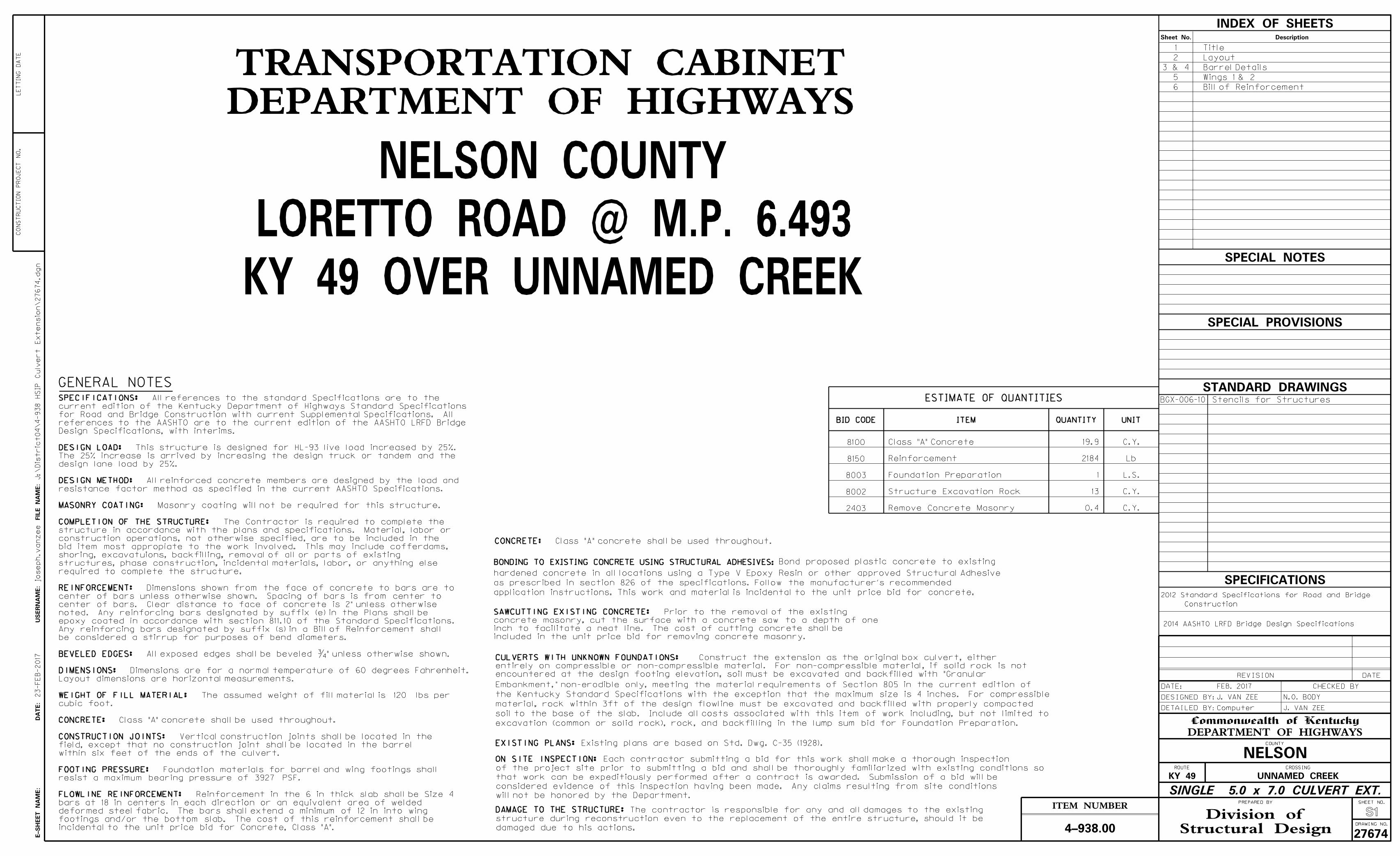
LAYOUT
S2
! CulvertFlow
N
13’-0" (Outlet End)
PLANSCALE = 1:48
Wing 1
Wing 2
SECTION ON !
20’-0" Inlet End (Existing + Proposed)
NELSON
KY 49 UNNAMED CREEK
27674
FEB. 2017
J. VAN ZEE
Computer
N.O. BODY
J. VAN ZEE
4-938.00
! Existing Roadway
Inlet End)
13’-0" (Existing*7’-0" Extension
90°0’0"
SCALE = 1:48
PLAN SHOWING REMOVAL
by the Engineer.existing box culvert or as directedRemove the hatched portion of the
with the Engineer. and in conjuction adjust as needed* Field verify and
in accordance with Section 610.03.03.Provide 4" diameter weep hole drains
Single 5’-0" x 7’-0" x 7’-0" R.C.B.C. Extension
0° Skew ~ KYHL-93 Loading ~ 0.50 Fill Slope
Unknown Foundation
*33’-0" (Out to Out Culvert Barrel)

ITEM NUMBER
DRAWING NO.
SHEET NO.
Commonwealth of Kentucky
DEPARTMENT OF HIGHWAYSCOUNTY
ROUTE CROSSING
PREPARED BY
DETAILED BY:
DESIGNED BY:
DATE: CHECKED BY
REVISION DATE
23-F
EB-2017
J:\
District04\4-938
HSIP
Culv
ert
Exte
nsio
n\27674.dgn
jose
ph.vanzee
US
ER
NA
ME:
FIL
E
NA
ME:
DA
TE:
E-S
HEET
NA
ME:
Structural DesignDivision of
BARREL
S3
Roughened Construction Joint
Keyed Construction Joint
D6 D6
C5 C5
1�"
Cl.
1�"
Cl.
8"
9"
7~
E9
@ 1’-0"
= 6’-
0"
(Ty
p. Each
Sid
ewall)
6" 6"
10" 10"5’-0"
10"
A Bars
B Bars
10"
(Top and Bottom Slab)
11"
10"
7’-
0"
1" Cl.
2"
Cl.
TYPICAL BARREL SECTION
SCALE = 1:16
1’-6"
Flowline Reinforcement. See General Notes.
6" 6"
6"
"A" 5~R53 @ 1’-0" = 4’-0"
"A"
6"
PLAN
SCALE = 1:48
NELSON
KY 49 UNNAMED CREEK
27674
FEB. 2017
J. VAN ZEE
Computer
N.O. BODY
J. VAN ZEE
4-938.00
12"
Concrete
Existing
New Concrete
new concrete
Material before placing
Apply Epoxy Bonding
DOWEL DETAILS
NOTE: The cost of drilling holes,
material shall be incidental to
the cost of Class "A" Concrete.
grouting, and epoxy bonding
Dowel
! Culvert
1’-6"
11~A1 @ 6" = 5’-0" (Top Slab)
9~B2 @ 6" = 4’-0" (Bottom Slab)
6"
6"
12"
6~C5 @ 1’-0" = 5’-0" (Each Sidewall)
6~D6 @ 1’-0" = 5’-0" (Each Sidewall)
3�"
Typ.
SCALE = 1:16
DOWEL LOCATION
10" 10"
9"
6~X55 @ 12" = 5’-0"
(Top & Bot. Slab)
7~
X55
@ 12
" = 6’-
0"
(Ty
p. Each
Sid
ewall)
X55 X55
B3
B3
B4
B4
Typ. Ea. Sidewall1~C5 & 1~D7
recommendations. Min. Lap 2’-2".and epoxy grout according to manufacturersNote: Drill B3 & B4 1’-0" min. into existing culvert
recommendations.and epoxy grout according to manufacturersNote: Drill D7 8" min. into existing culvert
6~E10 @ 1’-0" = 5’-0"
E10 E10
to the Reinforcement.and directed by the Engineer. Incidentalremoved concrete or elsewhere as neededNote: Trim E bars if necessary to fit around
epoxy grout
Grout bars with an
ITEM NUMBER
DRAWING NO.
SHEET NO.
Commonwealth of Kentucky
DEPARTMENT OF HIGHWAYSCOUNTY
ROUTE CROSSING
PREPARED BY
DETAILED BY:
DESIGNED BY:
DATE: CHECKED BY
REVISION DATE
23-F
EB-2017
J:\
District04\4-938
HSIP
Culv
ert
Exte
nsio
n\27674.dgn
jose
ph.vanzee
US
ER
NA
ME:
FIL
E
NA
ME:
DA
TE:
E-S
HEET
NA
ME:
Structural DesignDivision of
BARREL
S4
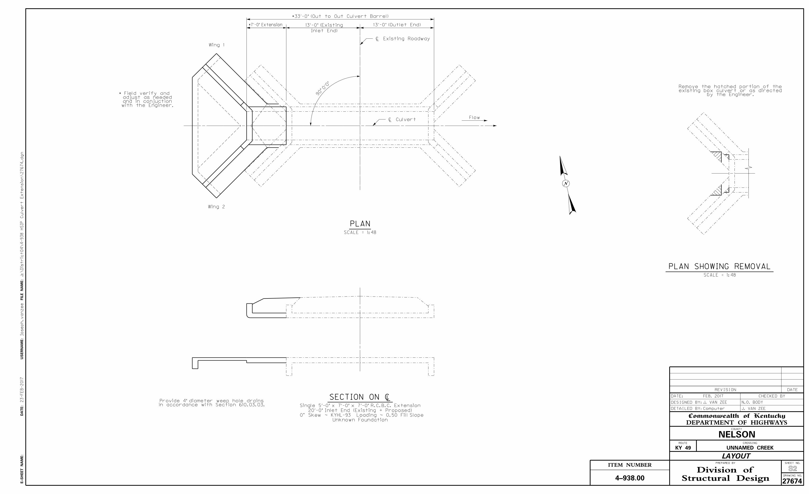
A1
SECTION ON !
SCALE = 1:12
8" Radius
P47 P44
P48 P45
R53
1’-0"
1’-3�
"
P49
P46
2’-
6"
1’-0"
1�"
Cl.
1�"
Cl.
1’-8"1�
"
Cl.
LEFT PARAPET
SCALE = 1:12
(Perpendicular to Parapet)
Q52 Q51
6"
4" 4"
*4’-
0"
1’-0"
P50
3�
"
4"
8"
6"
11"
LEFT END
SCALE = 1:12
(Perpendicular to Apron)
NELSON
KY 49 UNNAMED CREEK
27674
FEB. 2017
J. VAN ZEE
Computer
N.O. BODY
J. VAN ZEE
4-938.00
E10 E10
E10B2-B4
on top of solid rock if on a unyielding foundation.
yielding foundation (soil). Apron shall be poured
*Note: Apron shall be 4’-0" deep if culvert is on a

ITEM NUMBER
DRAWING NO.
SHEET NO.
Commonwealth of Kentucky
DEPARTMENT OF HIGHWAYSCOUNTY
ROUTE CROSSING
PREPARED BY
DETAILED BY:
DESIGNED BY:
DATE: CHECKED BY
REVISION DATE
23-F
EB-2017
J:\
District04\4-938
HSIP
Culv
ert
Exte
nsio
n\27674.dgn
jose
ph.vanzee
US
ER
NA
ME:
FIL
E
NA
ME:
DA
TE:
E-S
HEET
NA
ME:
Structural DesignDivision of
Wings 1 & 2
S5
6’-0"
2’-8"
10"
2’-6"
2’-
6"
10"
6"
! Culvert
4’-
2�
"
4’-2�" 3’-7�"
11’-0
"
45°
M Bars
E8
P Bars
K Bars
3"
13~
H3
5
@
10" =
10
’-0
" To
p
of
Ft
g.
13~
H3
6
@
10" =
10
’-0
" Bot
of
Ft
g.
PLAN
SCALE = 1:16
1’-3"
5’-
0"
4’-
6"
9’-
6"
1’-6"
11’-0"
3"
G Bars
13~D8 @ 10" = 10’-0" B.F.
G24~G34 @ 1’-0" = 10’-0" F.F.
K47
M Bars
"A" 5~M38,M39~M40 @ 1’-0" = 6’-0" B.F.
"A"
9"
"B" 5~M41,M42~M53 @ 1’-0" = 6’-0" F.F.
"B"
9"
3"
T54
WING ELEVATION
SCALE = 1:24
Roughened Construction JointD8
G24 to G34G11 to G23
2"
Cl.
M38
M38
M39
M41
M41
M42
T54
1’-3"
2’-
2"
6"
2’-8"2’-6"
10"
6’-0"
H35
H36
"C" 6~K37 @ 1’-0" = 5’-0" Bot of Ftg.
"C"
3"
Cl.
2"
Cl.
6"
"D" 6~K37 @ 1’-0" = 5’-0" Top of Ftg.
"D"
Fill Against
This Side
WING SECTION
SCALE = 1:24
NELSON
KY 49 UNNAMED CREEK
27674
FEB. 2017
J. VAN ZEE
Computer
N.O. BODY
J. VAN ZEE
4-938.006’-
4�
"
3’-2�" 9�"
G11~G23 @ 10" = 10’-0" B.F.
M40 M43

NELSON
KY 49 UNNAMED CREEK
27674
FEB. 2017
J. VAN ZEE
Computer
N.O. BODY
J. VAN ZEE
4-938.00
BILL OF REINFORCEMENT
MARK TYPE NO. SIZE LENGTH LOCATION A/E B/F C/G D/H
B4 Str. 2 5 3- 3 Bottom Slab
C5 Str. 14 5 7- 8 Sidewalls
D6 4 12 5 3- 6 Sidewalls 2- 7� 0-10 0- 5 2-10
D7 Str. 2 5 2-10 Sidewall Dowels
D8 4 26 5 3-10 B.F. Wings 1 & 2 2-11� 0-10 0- 5 3- 2
E9 Str. 14 4 6-10 Top & Bottom Slabs
E10 Str. 14 4 6-10 Sidewalls
G11 Str. 2 5 4-11 B.F Wings 1 & 2
G12 Str. 2 5 5- 3 B.F Wings 1 & 2
G13 Str. 2 5 5- 8 B.F Wings 1 & 2
G14 Str. 2 5 6- 1 B.F Wings 1 & 2
G15 Str. 2 5 6- 6 B.F Wings 1 & 2
G16 Str. 2 5 6-10 B.F Wings 1 & 2
G17 Str. 2 5 7- 3 B.F Wings 1 & 2
G18 Str. 2 5 7- 8 B.F Wings 1 & 2
G19 Str. 2 5 8- 1 B.F Wings 1 & 2
G20 Str. 2 5 8- 5 B.F Wings 1 & 2
G21 Str. 2 5 8-10 B.F Wings 1 & 2
G22 Str. 2 5 9- 3 B.F Wings 1 & 2
G23 Str. 2 5 9- 4 B.F Wings 1 & 2
G24 Str. 2 3 4-11 F.F. Wings 1 & 2
G25 Str. 2 3 5- 4 F.F. Wings 1 & 2
G26 Str. 2 3 5-10 F.F. Wings 1 & 2
G27 Str. 2 3 6- 4 F.F. Wings 1 & 2
G28 Str. 2 3 6- 9 F.F. Wings 1 & 2
G29 Str. 2 3 7- 3 F.F. Wings 1 & 2
G30 Str. 2 3 7- 9 F.F. Wings 1 & 2
G31 Str. 2 3 8- 2 F.F. Wings 1 & 2
G32 Str. 2 3 8- 8 F.F. Wings 1 & 2
G33 Str. 2 3 9- 2 F.F. Wings 1 & 2
G34 Str. 2 3 9- 4 F.F. Wings 1 & 2
H35 Str. 26 5 5- 8 Top Ftg Wings 1 & 2
H36 Str. 26 5 5- 8 Bot Ftg Wings 1 & 2
K37 Str. 24 5 12- 3 Ftg Wings 1 & 2
M38 8 10 5 13- 3 B.F. Wings 1 & 2 11- 1� 2- 2 1- 6� 1- 6�
M39 8 2 5 11- 5 B.F. Wings 1 & 2 9- 2� 2- 2 1- 6� 1- 6�
M40 8 2 5 9- 3 B.F. Wings 1 & 2 7- 1� 2- 2 1- 6� 1- 6�
M41 8 10 5 12-11 F.F. Wings 1 & 2 10- 9� 2- 2 1- 6� 1- 6�
M42 8 2 5 11- 0 F.F. Wings 1 & 2 8-10� 2- 2 1- 6� 1- 6�
M43 8 2 5 8-11 F.F. Wings 1 & 2 6- 9� 2- 2 1- 6� 1- 6�
P44 7 1 5 9- 0 B.F. Parapet Lt. End 5- 3 1-10� 1-10� 1- 4�
1- 4� 1- 4� 1- 4�
P45 7 1 5 9- 1 B.F. Parapet Lt. End 5- 1� 2- 0� 2- 0� 1- 5
1- 5 1- 5 1- 5
P46 7 1 5 9- 0 B.F. Parapet Lt. End 5- 3 1-10� 1-10� 1- 4�
1- 4� 1- 4� 1- 4�
P47 7 1 5 8- 4 F.F. Parapet Lt. End 5- 1� 1- 7� 1- 7� 1- 2
1- 2 1- 2 1- 2
P48 7 1 5 8- 3 F.F. Parapet Lt. End 5- 3 1- 6� 1- 6� 1- 1
1- 1 1- 1 1- 1
P49 7 1 5 8- 4 F.F. Parapet Lt. End 5- 1� 1- 7� 1- 7� 1- 2
1- 2 1- 2 1- 2
P50 Str. 2 5 7- 4 Bottom Slab Lt. End
Q51 7 1 5 27- 5 Appron Lt. End 16- 5� 5- 5� 5- 5� 3-10�
3-10� 3-10� 3-10�
Q52 7 1 5 27-11 Appron Lt. End 16- 9� 5- 7� 5- 7� 3-11�
3-11� 3-11� 3-11�
R53 11s 5 5 5-11 Parapet Wall (Left End) 2- 3� 0- 9 0- 2� 1- 9
0- 6� 0- 9�
T54 8 4 6 11-10 Top of Wings 1 & 2 10- 4� 1- 5� 0- 7� 1- 3�
X55 Str. 28 8 2- 0 Dowels
BILL OF REINFORCEMENT
MARK TYPE NO. SIZE LENGTH LOCATION A/E B/F C/G D/H
A1 1 11 5 7- 7 Top Slab 5-11 0-10 0- 5 6- 4
B2 1 9 5 8- 7 Bottom Slab 6-11 0-10 0- 5 7- 4
B3 Str. 2 5 3- 9 Bottom Slab
TYPE 1
A
D
BB C
TYPE 4
D
BC
A
TYPE 7
D
F
C
GA
B
E
TYPE 8
C
AD
B
F
D
B
C
A
E
TYPE 11
6"
ITEM NUMBER
DRAWING NO.
SHEET NO.
Commonwealth of Kentucky
DEPARTMENT OF HIGHWAYSCOUNTY
ROUTE CROSSING
PREPARED BY
DETAILED BY:
DESIGNED BY:
DATE: CHECKED BY
REVISION DATE
23-F
EB-2017
J:\
District04\4-938
HSIP
Culv
ert
Exte
nsio
n\27674.dgn
jose
ph.vanzee
US
ER
NA
ME:
FIL
E
NA
ME:
DA
TE:
E-S
HEET
NA
ME:
BILL OF REINFORCEMENT
S6
Structural DesignDivision of