Neighborhood Traffic Mitigation Program - Lincoln
23
City of Lincoln, Nebraska Neighborhood Traffic Mitigation Program (7-30-2009)
Transcript of Neighborhood Traffic Mitigation Program - Lincoln
City of Lincoln, Nebraska
Neighborhood Traffic Mitigation Program
(7-30-2009)

TABLE OF CONTENTS
CHAPTER 1: INTRODUCTION ............................................................................................................... 1
CHAPTER 2: TRAFFIC MITIGATION PROCESS ................................................................................ 2
CHAPTER 3: APPROVED TRAFFIC CALMING DEVICES................................................................. 3
3.1 TRAFFIC CIRCLE.............................................................................................................. 33.2 SPEED HUMPS.................................................................................................................. 53.3 SPEED TABLES................................................................................................................. 73.4 NARROWINGS: NECKDOWNS & CHOKERS.............................................................. 103.5 CHICANES......................................................................................................................... 133.6 DIVERTERS....................................................................................................................... 16
CHAPTER 4: IMPACTS OF TRAFFIC CALMING MEASURES ...................................................... 18
LIST OF TABLES
TABLE 1: SPEED IMPACTS OF TRAFFIC CALMING MEASURES........................................................ 18TABLE 2: VOLUME IMPACTS OF TRAFFIC CALMING MEASURES................................................... 19TABLE 3: COLLISION IMPACTS OF TRAFFIC CALMING MEASURES............................................... 19TABLE 4: APPLICATION GUIDELINES..................................................................................................... 20
LIST OF FIGURES
FIGURE 1: TYPICAL TRAFFIC CIRCLE.................................................................................................... 4FIGURE 2: ISLAND SECTION..................................................................................................................... 5FIGURE 3: TYPICAL SPEED HUMP........................................................................................................... 7FIGURE 4: TYPICAL SPEED TABLE.......................................................................................................... 9FIGURE 5: TYPICAL NECKDOWN............................................................................................................. 11FIGURE 6: TYPICAL CHOKER.................................................................................................................... 12FIGURE 7: RETROFIT CHICANE................................................................................................................ 14FIGURE 8: NEW CONSTRUCTION CHICANE.......................................................................................... 15FIGURE 9: TYPICAL DIVERTER................................................................................................................ 17

1
CHAPTER 1: INTRODUCTION
The Institute of Transportation Engineers' (ITE), Traffic Calming State-of-the-Practice (Ewing, 1999) defines trafficcalming as follows: "Traffic calming involves changes in street alignment, installation of barriers, and otherphysical measures to reduce traffic speeds and/or cut-through volumes in the interest of street safety, livability, andother public purposes." The ITE definition does not include non-engineering measures that modify street appearanceto affect vehicle speeds nor does it appease residents that perceive a traffic volume or speed problem. Examples ofthese non-engineering measures include roadside tree and flower planting, increased traffic enforcement, andneighborhood traffic safety campaigns.
Traffic Calming is used for volume control, vertical speed control and horizontal speed control. Volume controlmeasures consist of modifications that reduce the quantity of vehicles that use a specific roadway. Typical measuresinclude full street closures, half street closures, forced turn islands, and diverters. Vertical speed control measuresare elevated segments of roadway that require vehicles to slow down. Typical measures include speedhumps/bumps, speed tables, raised crosswalks, and raised intersections. Horizontal speed control measures alter thetypical straight-line traveled way of a specific roadway in an effort to reduce speed. Typical measures include trafficcircles, roundabouts, lateral shifts, chicanes and narrowings.
Traffic calming improvement projects should be implemented following a neighborhood traffic analysis thatconsiders the area roadway system that will be impacted by the proposed improvements. Spot improvements shouldbe more rare in occurrence and implementation will be heavily dependent on engineering judgment. An area-wideapproach is favored so traffic problems do not simply spill over from one neighborhood street to another. Thesuccess of traffic calming improvements is dependent on an appropriate level of public and resource agencyinvolvement in both disseminating the information and involving residents and agency representatives in selectingwhich device(s) will provide the greatest level of support and benefit to the neighborhood. There is no one devicethat should be used for any one particular problem, each problem must be considered independently. Engineeringjudgment must be used along with continuous community involvement to come to an appropriate solution. Traffic calming measures typically reduce speeds and volumes while increasing traffic safety. Waiting until afterstreets have been constructed and then retrofitting them with traffic calming treatments is not necessarily the mostcost-effective approach. Implementing traffic calming into the design and construction of new neighborhoods anddevelopments is the best approach.

2
CHAPTER 2: TRAFFIC MITIGATION PROCESS
Step 1: Written request made to the Public Works & Utilities Department, Traffic Operations Section, by arepresentative of the affected neighborhood, stating the specific issue(s), (i.e. speeding traffic, high traffic volumes,etc.) and location of the residential street(s) for which “Traffic Calming” is being requested. Times of day and daysof week when traffic issues are occurring, along with any other pertinent information should also be included to helpstaff facilitate traffic studies. (Please note that neighborhood requesting the “Traffic Calming”will be responsible to fund installation of any permanent solutions)
Step 2: Traffic Operations staff will conduct traffic volume and speed studies, observe conditions and becomefamiliar with the neighborhood characteristics. Traffic Operations staff will attempt to answer the following six (6)basic questions:
a) Are vehicle volumes higher than average for a residential street? (more than 1000 vehicles/day)b) Are vehicle speeds higher than average for a residential street? (greater than 30 mph)c) Is the traffic being generated from within the neighborhood or is it “cut-through” traffic?d) If this traffic was discouraged from using this residential street, are there other streets in the neighborhood where it could easily shift?e) What Traffic Calming Devices should be considered; andf) What is the * Area of Influence that would be impacted by the implementation of each specific Traffic Calming Device?g) What is the estimated cost of each device?
Step 3: If the traffic studies indicate that traffic volumes and/or vehicle speeds exceed the averages, TrafficOperations staff will require the neighborhood representative requesting “Traffic Calming” to gather signatures fromat least 67% of the property frontage located within the *Area of Influence first, acknowledging that there is atraffic problem and second, that they would like to begin the process of implementing “Traffic Calming” in theirneighborhood.
* The Area of Influence is the area within the neighborhood which will potentially experience dramatic negativechanges in traffic patterns if traffic calming is implemented.
Step 4: Once the required number of signatures are gathered and verified, Traffic Operations staff will lead a**neighborhood meeting, informing the residents of the types of “Traffic Calming” devices the City would consider,the locations of where the devices could be installed, the projected impact to the traffic within the neighborhood ifthe devices were installed, the approximate cost to implement each of the devices and the process for implementation& payment by the neighborhood, as well as for follow-up studies.
**The neighborhood meeting will also include City Council, Police and Fire representative(s).
Step 5: The neighborhood will submit a written notice to the Public Works & Utilities Department stating if theywould like to continue moving forward with implementation of “Traffic Calming”. If the desire is to continue withimplementation, the written notice shall also include which of the “Traffic Calming” devices and the locations of thedevices, the neighborhood would like to implement and the method and time line for payment by the neighborhood.
Step 6: Once payment is received, Traffic Operations will begin the process for any needed design, as well as forthe implementation of the requested “Traffic Calming”.
Step 7: Follow-up studies will be conducted to determine positive and negative impacts to traffic, as well as todetermine any other impacts to the neighborhood. If at any time following the studies, residents wish to modify orremove the “Traffic Calming” devices, signatures from at least 67% of the property frontage located within the Areaof Influence will be required.

3
CHAPTER 3: TRAFFIC CALMING DEVICES
3.1 TRAFFIC CIRCLE
Traffic circles are raised islands placed in intersections around which traffic circulates. They are sometimes calledintersection islands. They are usually circular in shape and landscaped in their center islands, though not always. Traffic circles are distinguished from roundabouts by smaller radii, correspondingly lower design speeds andcapacities, and traffic circles have no splitter islands on approaches therefore the appropriate signage will need to beinstalled to communicate counterclockwise circulation at the traffic circle.
Traffic circles should be used on streets where speed control is desired or intersections where improved side-streetaccess is desired. Traffic circles can be used on intersections of local or collector streets where only one lane fromeach direction enters the intersection. Traffic circles should not be used at intersections with high volumes of largetrucks or buses turning left.
Advantages and Disadvantages
Traffic circles are similar to roundabouts in their positive impacts on traffic safety and operations.
Traffic circles are likely to have minimal impact on traffic volume. Sometimes they can increase traffic volume byattracting motorists seeking reduced delay compared to stop controlled intersections. On the other hand, somevehicles may be diverted to adjacent roadways to avoid the device. Traffic circles, on average, reduce traffic volumeby 5 percent. If high volumes of left turning large vehicles exist, volume may decrease more due to left turnobstruction.
Speed near the intersection is reduced unless there was previously a stop sign in that direction; in which case, thespeed near the intersection will increase. Decreased speeds allow for increased access to the street from the sidestreet.
Depending on accident patters, there could be a decrease in accidents by reducing the likelihood of right-anglecrashes. Some intersections may see a decrease of up to 70 percent in crash rates. Emergency response will beaffected. There will also be a decrease in the amount of on-street parking and landscaping affecting line-of-sight.
Geometric Design
A typical traffic circle is shown in Figure 1. The travel path through the intersection has a horizontal curve radius of95 feet yielding a crossing speed of 20 mph. A low design speed was chosen to keep the circle as small as practical.

4
Figure 1: Typical Traffic Circle
The design vehicle for the typical circle is a school bus. A typical school bus should be able to pass through atreated intersection without having to mount the center island of the circle. If large truck, bus and/or emergencyvehicle concerns exist, the design process can include a "test run" where cones are placed in a circle in theintersection and the diameter is adjusted as necessary as the vehicle in question (usually a fire truck) attempts tonegotiate around the circle. Trucks and buses generally cannot make left turns in the prescribed manner, that is, bycirculating counterclockwise around the center island. Most traffic circles, including the typical circle in Figure 1, have circular center islands and circular perimetersformed by the intersection corners and all traffic circles should be constructed without driveways within them. Where intersecting streets differ significantly in width, the center island may be elongated to better fit theintersection. An elongated circle consists of half circles with tangent sections between them. Most traffic circles are deployed at four-way intersections. This is where the greatest safety benefits are gained. Driveways should not enter into a traffic circle intersection. For traffic circles at "T" intersections, curbs should beeither extended at the entrance and exit to the intersection or indented within the intersection to ensure adequatedeflection of vehicle paths along the top of the "T." The center island of a traffic circle has the cross section shownin Figure 2.

5
Figure 2: Island Section
For aesthetics and to draw motorists' attention, the center island should be landscaped. Landscaping should becarefully planned for unrestricted visibility. To preserve sight lines, trees should have clear stem heights of at leasteight feet and should be no more than four inches in diameter to ensure that they break away upon impact. Bushesor shrubs should grow to no more than two feet above the top of the curb. Groundcover plantings are particularlyuseful for landscaping of islands because they leave sight lines open and pose no danger to out-of-control drivers.
For visibility and drainage, the circulating lane will ordinarily slope away from the center island of the traffic circle. A slope of one to two percent offers these advantages without the risk of heavy vehicles turning over due to reversesuperelevation.
Mini circles that fit within the curb lines of smaller intersections can be considered on an exception basis. Minitraffic circles can be considered where two conditions are met: (1) intersection widening is infeasible and (2)entering volumes are less than 500 vpd (50 vehicles during the peak hour). At mini traffic circles, buses and trucksare permitted to make left turns in front of the center island. Island radius will depend upon curb radii and lanewidths. Since island radius is smaller than lane width, benefits of traffic speed reduction and traffic safety will bereduced.
3.2 SPEED HUMPS
Speed humps are rounded raised areas placed across the road to reduce vehicle speeds. They are also referred to asundulations or road humps. They are most effective at reducing speeds when placed in series.
Speed humps are not the same as speed bumps. Within typical residential speed ranges, humps create a gentlevehicle rocking motion that causes some driver discomfort and results in most vehicles slowing to 20 mph at eachhump and 25 to 30 mph between properly spaced humps in a system. A bump, on the other hand, causes significantdriver discomfort at typical residential speeds and generally results in vehicles slowing to 5 mph or less at the bump. Speed bumps jolt vehicles, even at low speed, and create potential liability. Speed bumps may cause damage tovehicles, and injury to passengers and cyclists. At high speeds a hump can act as a bump and jolt the vehiclessuspension and its occupants or cargo. Speed humps are typically not effective below 15 mph.
Speed humps should be used on local streets where speed control is desired or where cut-through traffic is to bediscouraged. Speed humps should not be used on major roads, bus routes, or primary emergency response routes. They should be placed mid-block, not at intersections and will have advanced warning signs to inform drivers. Theycannot be used on grades greater than eight percent because of safety concerns. Speed humps work well with othertraffic calming devices such as curb extensions.
6
Advantages and Disadvantages
Speed humps are an effective tool in reducing travel speeds to be consistent with posted speed limits. They areeffective in reducing the speeds of the higher speed drivers and slightly effective in reducing speeds on paralleluntreated streets (2 mph reduction). On average, speed humps reduce 85th percentile travel speeds by about 7 mph. The average speeds over speed humps is about 20 mph. Speeds typically increase approximately 0.5 mph midwaybetween humps for each 100 feet of separation.
Traffic volumes tend to decrease on streets with speed humps. The amount of volume reduction depends on theamount of speed reduction and availability of alternate routes. Traffic volume reduction averages about 20 percent. On average, parallel untreated streets experienced slight increases in traffic volume of about four percent.
Speed humps have many effects on safety. The incidence of crashes on treated streets decreases an average of 39percent. Emergency response vehicles may be damaged if the hump is not designed properly. There may also be anincrease in traffic noise in the vicinity of the hump.
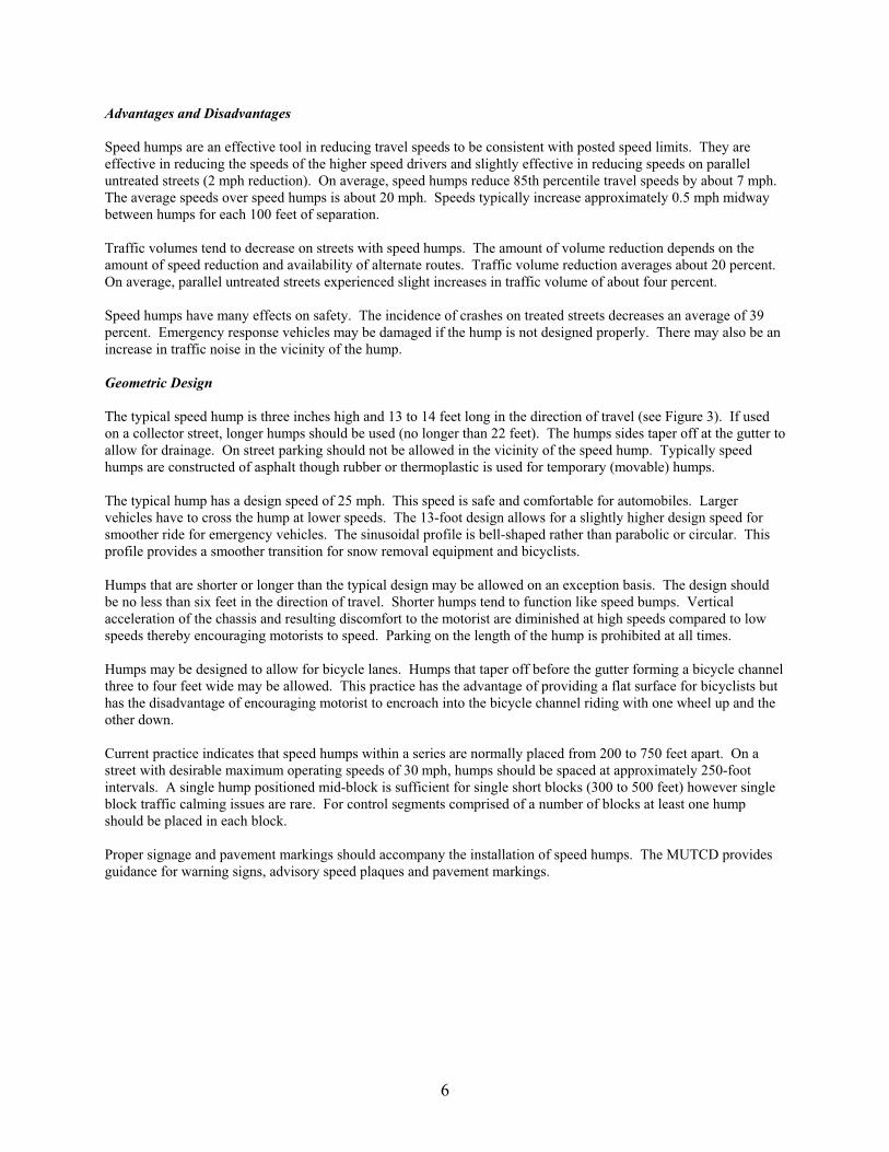
Geometric Design
The typical speed hump is three inches high and 13 to 14 feet long in the direction of travel (see Figure 3). If usedon a collector street, longer humps should be used (no longer than 22 feet). The humps sides taper off at the gutter toallow for drainage. On street parking should not be allowed in the vicinity of the speed hump. Typically speedhumps are constructed of asphalt though rubber or thermoplastic is used for temporary (movable) humps. The typical hump has a design speed of 25 mph. This speed is safe and comfortable for automobiles. Largervehicles have to cross the hump at lower speeds. The 13-foot design allows for a slightly higher design speed forsmoother ride for emergency vehicles. The sinusoidal profile is bell-shaped rather than parabolic or circular. Thisprofile provides a smoother transition for snow removal equipment and bicyclists.
Humps that are shorter or longer than the typical design may be allowed on an exception basis. The design shouldbe no less than six feet in the direction of travel. Shorter humps tend to function like speed bumps. Verticalacceleration of the chassis and resulting discomfort to the motorist are diminished at high speeds compared to lowspeeds thereby encouraging motorists to speed. Parking on the length of the hump is prohibited at all times.
Humps may be designed to allow for bicycle lanes. Humps that taper off before the gutter forming a bicycle channelthree to four feet wide may be allowed. This practice has the advantage of providing a flat surface for bicyclists buthas the disadvantage of encouraging motorist to encroach into the bicycle channel riding with one wheel up and theother down.
Current practice indicates that speed humps within a series are normally placed from 200 to 750 feet apart. On astreet with desirable maximum operating speeds of 30 mph, humps should be spaced at approximately 250-footintervals. A single hump positioned mid-block is sufficient for single short blocks (300 to 500 feet) however singleblock traffic calming issues are rare. For control segments comprised of a number of blocks at least one humpshould be placed in each block.
Proper signage and pavement markings should accompany the installation of speed humps. The MUTCD providesguidance for warning signs, advisory speed plaques and pavement markings.
7
Figure 3: Typical Speed Hump
3.3 SPEED TABLES
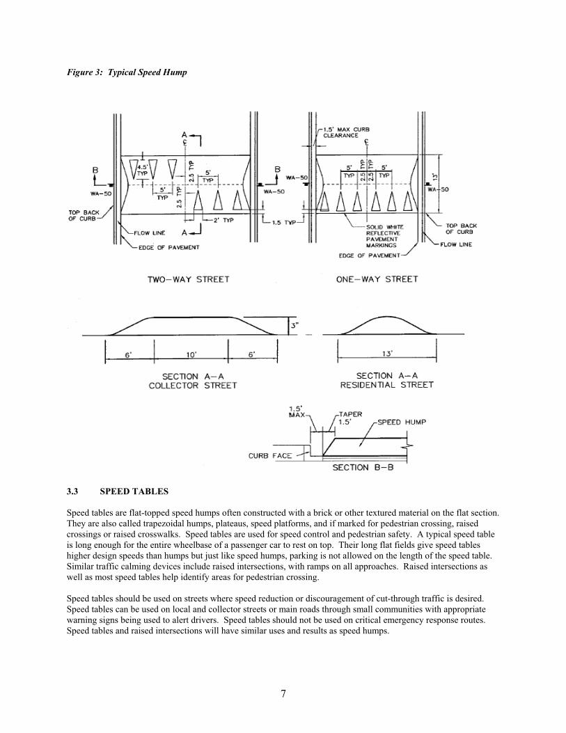
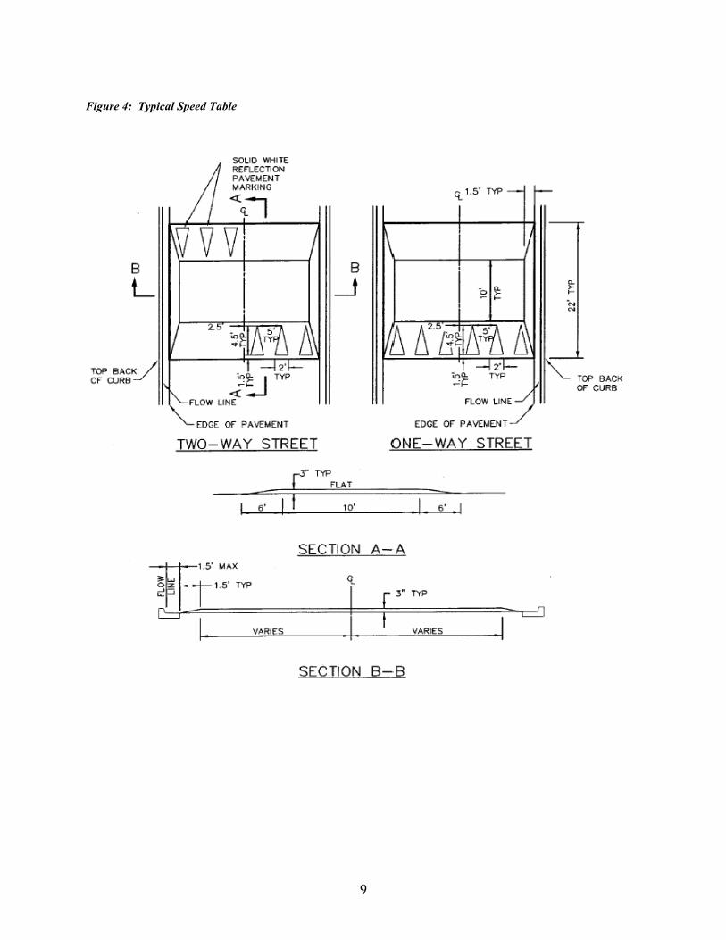
Speed tables are flat-topped speed humps often constructed with a brick or other textured material on the flat section. They are also called trapezoidal humps, plateaus, speed platforms, and if marked for pedestrian crossing, raisedcrossings or raised crosswalks. Speed tables are used for speed control and pedestrian safety. A typical speed tableis long enough for the entire wheelbase of a passenger car to rest on top. Their long flat fields give speed tableshigher design speeds than humps but just like speed humps, parking is not allowed on the length of the speed table. Similar traffic calming devices include raised intersections, with ramps on all approaches. Raised intersections aswell as most speed tables help identify areas for pedestrian crossing.
Speed tables should be used on streets where speed reduction or discouragement of cut-through traffic is desired. Speed tables can be used on local and collector streets or main roads through small communities with appropriatewarning signs being used to alert drivers. Speed tables should not be used on critical emergency response routes. Speed tables and raised intersections will have similar uses and results as speed humps.

8
Advantages and Disadvantages
Speed tables are an effective tool for decreasing traffic speeds. There is an average of 18 percent decrease in 85thpercentile travel speeds. They also show a 12 percent decrease in traffic volumes. Roads where speed tables areplaced have an average of a 45 percent decrease in crashes resulting in increased pedestrian safety.
Speed tables provide opportunity for attractive pavement treatments that can lead to higher costs. If no attractivepavement treatments are used, aesthetic quality is questionable.
Emergency response vehicles have fewer delays due to speed tables than speed humps but still experience minordelays.
Geometric Design
The typical speed table is three inches high and 22 feet long in the direction of travel (see Figure 4). The plateau(flat top) is ten feet long, and each ramp is six feet long. The plateau is made of asphalt, concrete, stamped asphaltor concrete, or other approved patterned materials. The ramps are sinusoidal in shape and ordinarily made of asphaltthough concrete, brick, and concrete pavers are also used. Speed tables can be designed with or without taperedsides. For speed tables used as pedestrian crosses, ramps from the sidewalk must meet ADA standards. Such speedtables will require storm water drainage reconstruction. Speed tables with tapered sides will be less costly sincethere will be no drainage reconstruction. The taper can allow for a bicycle lane but may lead to vehicles driving withone wheel up and one wheel down through the speed table.
The typical speed table has a design speed of 30 mph. This speed is safe and comfortable for automobiles. Largervehicles have to cross the table at lower speeds.
The plateaus of speed tables may be as short as eight feet in the direction of travel. Speed table will lose theireffectiveness if more than 50 feet long. On transit and emergency response routes, plateaus of 20 feet or more arerecommended so that long wheelbase vehicles can cross with all wheels on the flat portion. All other dimensionalrequirements for speed humps (height, profile development, etc.) also apply to speed tables.
Parking on the length of the hump is prohibited at all times. Proper signage and pavement markings shouldaccompany the installation of speed tables. The MUTCD provides guidance for warning signs, advisory speedplaques and pavement markings.
9
Figure 4: Typical Speed Table
10
3.4 NARROWINGS: NECKDOWNS & CHOKERS
Narrowings are short roadway segments that are narrower than the typical roadway section. Typical narrowingsinclude neckdowns, chokers, and island narrowings. Narrowings increase pedestrian safety but have little effect ontraffic volume or speed.
Neckdowns are curb extensions at intersections that reduce roadway width curb-to-curb. They are sometimes callednubs, bulbouts, corner bulges, knuckles, or intersection narrowings. Placed at the entrance to a neighborhood, oftenwith textured paving between them, they are called gateways. Their effect on vehicle speeds is limited by theabsence of pronounced vertical or horizontal deflection. Instead, their primary purpose is to "pedestrianize"intersections.Chokers are curb extensions or edge islands at mid-block that narrow a street at that location. In differentconfigurations, they are called mid-block narrowings, mid-block yield points, parallel chokers, angled chokers,twisted chokers, angle points, and pinch points. If marked as crosswalks, they are also called safe crosses. Chokerscan leave the street cross section with two lanes, albeit narrower lanes than before, or take it down to one lane.
Narrowings should be used adjacent to intersections where parking is restricted or to shorten pedestrian crossings. Narrowings should be used on local and collector streets and main roads through small communities. Narrowingsare effective for improving pedestrian crossings and work well in addition to many other traffic calming devices.
Advantages and Disadvantages
Neckdowns and chokers have similar impacts on traffic safety and operations.
They typically have little or no effect on traffic volumes unless there is a reduction in the number of lanes. Highlyeffective narrowings may achieve volume reductions of 10 percent. Narrowings have a minimal impact on trafficspeeds unless there is a severe restriction in the shy distance to instigate slower speeds.
There is potential for improved pedestrian safety due to improved visibility of crossing point, shorter crosswalks, andno on-street parking near the crosswalk. However, narrowings create a less safe environment for bicycles due to lessvisibility when they are in the narrowed area.
Snow maintenance is typically slowed by roadway narrowings and roadway design should include vertical elementssuch as bollards to assist the snowplow operators in identifying the locations of curb extensions. The narrowingsprovide landscape areas that enhance aesthetics and define neighborhood entries.
Narrowings may create drainage issues where curb and gutter exist and they may also create some loss in parking.
Geometric Design
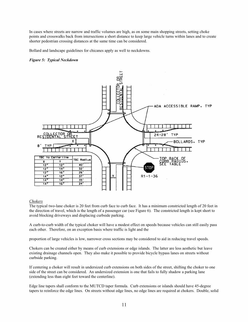
NeckdownsThe typical neckdown is used in connection with on-street parking and, unlike a conventional intersection with alarge curb return radius, offers a short crossing distance and high visibility for pedestrians (see Figure 5). In thetypical design, the curb return radii and street widths are such that single unit trucks can stay to the right of thecenterlines when making right turns.
When streets are wide to begin with and have parking lanes on main and cross streets, intersections can be narroweddown without necessitating encroachment by trucks into opposing lanes. When streets are narrow and/or withoutcurbside parking, intersections cannot be narrowed down without encroachment. Many jurisdictions keep cornerradii small and allow large vehicles to swing wide into the opposing lane when making right turns. On an exceptionbasis, this practice can be considered when volumes entering the intersection are less than 500 vpd (50 vehiclesduring the peak hour), heavy vehicle traffic is less than two percent of the daily total, and the roadway is not a transitroute. Otherwise, curb radius should be large enough to allow a single unit truck (or bus) to maneuver the cornerwithout encroaching into the opposite lane.
11
In cases where streets are narrow and traffic volumes are high, as on some main shopping streets, setting chokepoints and crosswalks back from intersections a short distance to keep large vehicle turns within lanes and to createshorter pedestrian crossing distances at the same time can be considered.
Bollard and landscape guidelines for chicanes apply as well to neckdowns.
Figure 5: Typical Neckdown
ChokersThe typical two-lane choker is 20 feet from curb face to curb face. It has a minimum constricted length of 20 feet inthe direction of travel, which is the length of a passenger car (see Figure 6). The constricted length is kept short toavoid blocking driveways and displacing curbside parking.
A curb-to-curb width of the typical choker will have a modest effect on speeds because vehicles can still easily passeach other. Therefore, on an exception basis where traffic is light and the
proportion of large vehicles is low, narrower cross sections may be considered to aid in reducing travel speeds.
Chokers can be created either by means of curb extensions or edge islands. The latter are less aesthetic but leaveexisting drainage channels open. They also make it possible to provide bicycle bypass lanes on streets withoutcurbside parking.
If centering a choker will result in undersized curb extensions on both sides of the street, shifting the choker to oneside of the street can be considered. An undersized extension is one that fails to fully shadow a parking lane(extending less than eight feet toward the centerline).
Edge line tapers shall conform to the MUTCD taper formula. Curb extensions or islands should have 45-degreetapers to reinforce the edge lines. On streets without edge lines, no edge lines are required at chokers. Double, solid

12
yellow lines should only be used on local streets.
When used in connection with curbside parking, chokers may extend to the edge of the travel lane to form protectedparking bays. Absent an edge line or marked parking spaces, chokers should extend no farther than eight feet towardthe centerline.
Curb extensions or edge islands that form chokers should have vertical elements to draw attention to them,preferably landscaping. Any vertical element shall be of breakaway or yielding design. Bollard and landscapingguidelines for chicanes also apply to chokers.
Within the choker, a change in pavement material should be considered. Textured surfaces, such as stamped asphaltor concrete, reinforce the visual cues of narrowing and landscaping thereby warning motorists of the constriction andemphasizing its special character.
For chokers that serve as pedestrian peninsulas, barrier curbs shall be used to provide an added measure ofpedestrian protection. Otherwise, barrier or mountable curbs shall be selected on a case-by-case basis.
Figure 6: Typical Choker

13
3.5 CHICANES
Chicanes are curb extensions that alternate from one side of the street to the other forming s-shaped curves. Theyare also referred to as deviations, serpentines, and reversing curves.
Chicanes should be used when a reduced line-of-sight is desired or in addition to other forms of street narrowing forspeed control. Chicanes are appropriate for mid-block locations only and are most effective with equivalent volumeson both approaches. They are most effective when in a series of at least three curb extensions, meaning a vehiclemust change their direction of travel at least twice to maneuver through the chicane.
Advantages and Disadvantages
Chicanes are a form of street narrowing. They typically have little or no effect on traffic volumes unless there is areduction in the number of lanes. The curvilinear alignment requires additional maneuvering and reduces drivers'line-of-sight, but this has little to no impact on traffic speeds unless there is significant reduction in line-of-sight. The reduction in line-of-sight creates hazardous conditions for pedestrians. There is little impact on emergencyvehicle time and snow maintenance.
Chicanes create a substantial decrease in the amount of on-street parking (about a 2/3 reduction within the vicinity ofthe device). This can be beneficial depending on neighborhood issues. Currently there is no documented impact onvehicular crashes due to chicane installation.
The right-of-way in a chicane should be parallel to the curbline although construction may require additionalright-of-way to be effective but also will allow for landscaping opportunities.
Geometric Design
Chicanes can be created either by means of curb extensions or edge islands. The latter are less attractive but leaveexisting drainage channels open and tend to be less costly to construct. The typical chicane has trapezoidal islandsbased on the finding that this shape is more effective in reducing speeds than is a semi-circular shape.
Edge line tapers shall conform to MUTCD taper standards. The curb extensions or edge islands should have45-degree tapers to reinforce the edge lines.
Curb extensions should have vertical elements to draw driver attention. Trees and other landscape materials maymeet this requirement. Care should be taken to maintain plantings at these locations to avoid obstructing intersectionand driveway sight distance requirements.
Barrier curbs should be used on curb extensions and edge islands that form chicanes. Bollards should be placed atall changes in horizontal alignment to clearly delineate the curb line for snow removal operations. The bollards shallbe placed with a minimum of two feet and a maximum of three feet from the face of the curb to the face of thebollard. Mountable curbs may be used if emergency vehicle needs must be met or if edge islands within the chicaneare not expected to serve as pedestrian refuge.
Figure 7 shows a retrofit chicane with the existing roadway already in place. Construction of the two islands withbollards, revised signing and pavement marking are the additions needed to construct a retrofit chicane.
Appropriate warning signs will be installed to inform drivers of approaching road changes. The typical chicaneseparates opposing traffic by means of double, solid yellow lines except when used on local streets. This may not beenough to discourage some motorists from cutting across the centerline. To further discourage this behavior, araised median may be installed. The median should be a minimum of four feet wide and mountable with or withoutlandscaping.
On an exception basis, chicanes formed with parallel parking bays alternating from one side of the street to the othercould be considered. This is a relatively inexpensive design option and is common in redesigned streets. This

14
option makes negotiating a chicane even more difficult due to watching for vehicles pulling in and out of parkingspaces with reduced visibility. This is also the primary reason as to why driveways are not allowed in chicanes.
Figure 7: Retrofit Chicane

15
Figure 8 shows a new construction chicane. It is important that the right of way lines parallel the curb line in thisnew construction.
Figure 8: New Construction Chicane
16
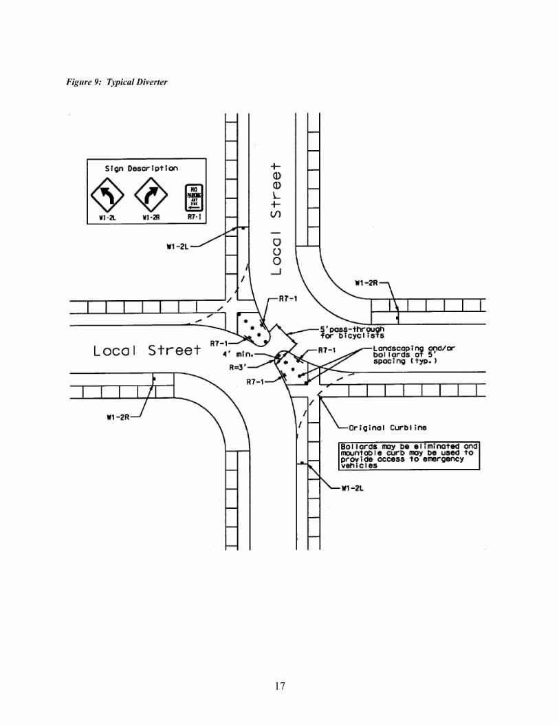
3.6 DIVERTERS
Diagonal diverters are barriers placed diagonally across a four-way intersection, blocking through movement. Theyare also called full diverters and diagonal road closures.Diverters are a volume reducing device that should be used on local streets where cut-through traffic is a problem. They should only be used after other measures have failed. Diverters should be used in sets to make travel throughneighborhoods more circuitous. They are typically staggered internally in a neighborhood, which leaves throughmovement possible but less attractive than alternative (external) routes.
Advantages and Disadvantages
Diverters reduce through volume traffic by diverting it to other streets. The typical objective of diverters is to routecut-through traffic to collectors or arterials. Diverters can have a substantial impact on traffic volumes depending onthe percentage of cut-through traffic versus local traffic. Average reduction in traffic volume is 35%. Speeds arereduced adjacent to the diverter intersection, but there are only minimal speed reductions at mid-block locations.
Safety benefits of diverters are achieved by diverting cut-through traffic and by reducing accidents at the diverterintersection through elimination of all conflict points. The intersection will require no police enforcement and is notas restrictive as street closure.
Traffic may be redirected to other local streets so diverters should be used as part of a comprehensive area-wideplan. Continuous routing opportunities are maintained but there may be increased trip length for some drivers. Thediverter will be in effect at all times, even if cut-through problem exists only at certain times of the day. Diverters may be designed with minimal landscaping and mountable curbs for emergency vehicle needs but shouldnot be used on critical emergency response routes.
Geometric Design
Diverters present few design issues as they are simple barriers blocking one or more movements at an intersection asseen in Figure 9.
Advance warning signs must be installed prior to the diverter to alert drivers of the geometrical change in theroadway. Diagonal diverters should have clear widths sufficient for single unit trucks (or buses if on a transit route)to make turns at treated intersections without encroaching opposing lanes. Diagonal diverters may have curb rampsup to the sidewalk at the corners to allow pedestrian traffic across the diverter. Such ramps must meet theAmericans with Disabilities Act (ADA) Standards for Accessible Design, 28 CFR Part 36, Appendix A.
Diagonal diverters can be landscaped for aesthetic reasons and to reinforce the idea that barriers are not to betraversed. On an exception basis, bollards may be used instead of landscape materials. Where traversal byemergency vehicles is anticipated, a clear width of at least ten feet shall be left free of landscaping and bollards.
Diagonal diverters shall have barrier curbs to discourage unauthorized vehicles from traversing them. Curb heightsshall meet Lincoln's standard barrier curb height requirements. Special consideration will be taken if emergencyvehicles needs must be met. If a mountable curb is used for emergency vehicle purposes, the height must be largeenough to discourage private vehicles from mounting the curb.
17
Figure 9: Typical Diverter

18
CHAPTER 4: IMPACTS OF TRAFFIC CALMING MEASURES
Traffic calming involves matching engineering measures to specific traffic problems. From the measures justdescribed, the most cost-effective and conservative measure that will solve the problem should be used. It isimportant to stress the importance of community involvement throughout the decision making process. Manycommunities employ a 60 percent approval need in which 60 percent of the residents and business owners in the areamust understand and approve of the traffic calming project.
To assist in the choice of traffic calming devices, this section summarizes speed, volume, collision and cost impactsof different traffic calming measures. Impact data is taken from ITE's Traffic Calming State-of-the-Practice manual,which draws on before-and-after studies to derive average values including standard deviations. Sample averagescan be used to initially screen traffic calming measures for further consideration.
Table 1 is a summary of the impacts of several traffic calming devices on speed. As can be seen, vertical speedcontrol measures are much more effective in reducing speeds than horizontal speed control measures.
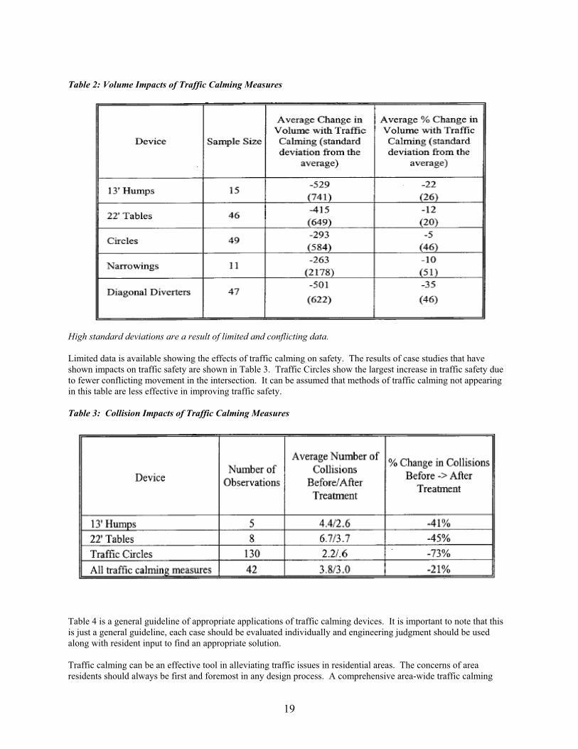
The most effective forms of volume control can be seen in Table 2. As is to be expected, diagonal diverters are themost effective form of volume control. Vertical control devices such as humps are more effective than horizontalcontrol devices such as narrowings.
19
Table 2: Volume Impacts of Traffic Calming Measures
High standard deviations are a result of limited and conflicting data.
Limited data is available showing the effects of traffic calming on safety. The results of case studies that haveshown impacts on traffic safety are shown in Table 3. Traffic Circles show the largest increase in traffic safety dueto fewer conflicting movement in the intersection. It can be assumed that methods of traffic calming not appearingin this table are less effective in improving traffic safety.
Table 3: Collision Impacts of Traffic Calming Measures
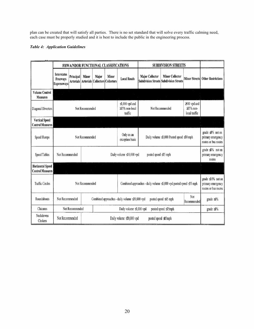
Table 4 is a general guideline of appropriate applications of traffic calming devices. It is important to note that thisis just a general guideline, each case should be evaluated individually and engineering judgment should be usedalong with resident input to find an appropriate solution.
Traffic calming can be an effective tool in alleviating traffic issues in residential areas. The concerns of arearesidents should always be first and foremost in any design process. A comprehensive area-wide traffic calming
20
plan can be created that will satisfy all parties. There is no set standard that will solve every traffic calming need,each case must be properly studied and it is best to include the public in the engineering process.
Table 4: Application Guidelines

21
Source Materials:
Wiersig, Douglas W. 1997. Guidelines for the Design and Application of Speed Humps. Institute of TransportationEngineers Traffic Engineering Council Speed Humps Task Force (June).
Municipality of Anchorage, Alaska. 2001. Traffic Calming Protocol Manual. Municipality of Anchorage TrafficDepartment (March).
Delaware State Department of Transportation. 2000. Traffic Calming Design Manual. Delaware Register ofRegulations, Vol. 4, Issue 3 (September 1).
Noyes, Pat. 1998. Traffic Calming Primer. Harris, Lisa. 1997. Traffic Calming in Kansas: Examples from Topeka and Manhattan.Kansas University Transportation Center Newsletter.
Traffic Calming. 1994. ITE 1994 Compendium of Technical Papers.
www.trafficcalming.org. Accessed June 2004.
Schoneman, Noel F. Low Cost vs. High Cost Traffic Calming Devices in Seattle. Seattle Transportation, City ofSeattle. 2003.
Wilmington Area Planning Council. 2002. Old Newark Traffic Calming Plan (March).
Cockril, Scott. City of Lincoln.
http://www.ite.org/traffic/tcdevices.htm. Accessed June 2004.