Negative Pressure Units - deconta
34
Original instruction manual Negative Pressure Units green dec G 700 Manufacturer: deconta GmbH Im Geer 20, 46419 Isselburg Designation / Type No.: Negative pressure unit green dec G 700 Typ 704 Serial No.: .................
Transcript of Negative Pressure Units - deconta

Original instruction manual
Negative Pressure Units
green dec
G 700
Manufacturer: deconta GmbH Im Geer 20, 46419 Isselburg Designation / Type No.: Negative pressure unit green dec G 700 Typ 704 Serial No.: .................

Instruction Manual Negative Pressure Unit green dec G 700
Version 3 Page 2
Table of contents 1. Basic safety advice ............................................................................................................ 3
1.1. Intended use .................................................................................................................................... 4 1.2. Dangers ........................................................................................................................................... 5
2. Transport and storage ....................................................................................................... 6 2.1. Transport .......................................................................................................................................... 6 2.2. Storage ............................................................................................................................................ 6
3. Delivery contents ............................................................................................................... 6 4. Technical data .................................................................................................................... 7
4.1. Performance data ............................................................................................................................ 7 4.2. Connections, dimensions, weights .................................................................................................. 7 4.3. Filter description / classification ....................................................................................................... 8
4.3.1. Pre-filter ................................................................................................................................... 8 4.3.2. Bag filter ................................................................................................................................... 9 4.3.3. HEPA filter ............................................................................................................................... 9
5. Technical description ...................................................................................................... 10 5.1. Unit description .............................................................................................................................. 10 5.2. Control SRE connect ..................................................................................................................... 10
6. Assembly instruction ....................................................................................................... 11 7. Initial operation ................................................................................................................ 12
7.1. Preparations .................................................................................................................................. 12 7.2. Control SRE connect ..................................................................................................................... 13
7.2.1. Create your user account ...................................................................................................... 14 7.2.2. Add the device to your user account ..................................................................................... 15 7.2.3. Manual mode ......................................................................................................................... 18 7.2.4. Automatic mode ..................................................................................................................... 19 7.2.5. Day / Night setting ................................................................................................................. 20 7.2.6. Standby mode ........................................................................................................................ 20 7.2.7. Consumption .......................................................................................................................... 21 7.2.8. Dust sensor ............................................................................................................................ 21 7.2.9. Service ................................................................................................................................... 22 7.2.10. Software packages ................................................................................................................ 24 7.2.11. Device information ................................................................................................................. 25 7.2.12. Alarms .................................................................................................................................... 25 7.2.13. Turn off the device ................................................................................................................. 27
8. Maintenance ..................................................................................................................... 28 8.1. Information on filter change ........................................................................................................... 28 8.2. Filter change .................................................................................................................................. 29
9. Possible disturbances and their elimination ................................................................. 32 10. Sound level measurements ............................................................................................. 33 11. Declaration of Conformity ............................................................................................... 34

Instruction Manual Negative Pressure Unit green dec G 700
Version 3 Page 3
The copyright of this instruction manual remains with deconta. This manual is intended for assembly, operation and maintenance personnel. It contains instructions and drafts of technical nature which may neither be distributed nor used in any unauthorised way for competitive purposes or passed on to others.
1. Basic safety advice The operation of the negative pressure unit (NPU) must only be carried out by trained competent personnel. The information and instructions contained within this publication are of paramount importance to the user. The manual is always to be kept in the immediate proximity, accessible to all personnel. deconta insists as the NPU user you follow the information and instruction contained within the handbook and only use it in accordance with the regulations and never use this Negative Pressure Unit in an inappropriate way. In case of non-observance, deconta assumes no liability. To ensure safe operation of the NPU, the following must be strictly observed:
Do not use in potentially explosive atmospheres. Maintenance work, including removal and replacement of the filters, may only be
carried out by authorized persons wearing suitable protective clothing. The device must be completely disconnected from the power supply during all
repairs and maintenance work. The safety and protective systems must be maintained and functioning correctly. Safety instructions affixed to the unit must be maintained in a legible condition and
must be adhered to. General, legal and other binding regulations and procedures for accident prevention
and handling of hazardous substances must be observed. To ensure safety, modifications to the device are not permitted. To avoid damage, never operate the unit without built-in filters. ATTENTION! The negative pressure units are not suitable for use in condensing, corrosive, flammable and explosive atmospheres. We explicitly refer to the additional regional and national safety measures and regulations when operating the device technology. The filter must be checked by an oil thread test (DOP / DEHS) upon initial operation and after each HEPA filter change by the operator. Devices with SRE connect control should be checked and calibrated once a year by the deconta service. In addition to the instruction manual, general, legal and other binding regulations on accident prevention and environmental protection must be observed.

Instruction Manual Negative Pressure Unit green dec G 700
Version 3 Page 4
1.1. Intended use The negative pressure unit is designed for filtering non-condensing, asbestos-contaminated room air, in the temperature range up to +45 ° C, with exhaust air discharged to atmosphere. In the case of asbestos removal work within contaminated areas, it is expected that airborne asbestos fibres will escape the contaminated area and pose a risk to human health and environment. For these reasons, contaminated areas are separated from the asbestos-free areas and kept under dynamic negative pressure by means of negative pressure units. An integrated filter system reduces the airborne asbestos fiber concentration to a figure of max. 1000F/m3 in the exhaust air. The exhaust air is expelled to the open air. The device is not suitable for filtering flammable gases or dusts. The user must comply with the specified operating parameters of this manual. The device may only be used according to its intended use. Any further use beyond this is not intended. The user is liable for any damages or injuries of any kind whatsoever.

Instruction Manual Negative Pressure Unit green dec G 700
Version 3 Page 5
1.2. Dangers
DANGER Electric shock due to faulty mains cable. Touching a defective mains cable may result in death or serious injury. Do not damage the mains cable (e.g. by vehicle overrun, tearing, squeezing). Regularly check the mains cable for damage. Have defective mains cable replaced before use by the deconta service or a
qualified electrician
CAUTION Damage due to unsuitable mains voltage. The device can be damaged if it is connected to an unsuitable mains voltage. Check whether the voltage indicated on the rating plate matches the local mains
voltage.
WARNING Hazardous materials. The following materials must not be filtered: Hot materials (glowing cigarettes, hot ash, etc.) Combustible, explosive, aggressive materials and dusts
WARNING Contaminated filters. Filter changes may only be carried out by authorised persons who carry suitable
protective clothing. Dispose of the filter according to the legal requirements.

Instruction Manual Negative Pressure Unit green dec G 700
Version 3 Page 6
2. Transport and storage 2.1. Transport A crane / forklift with a minimum lifting capacity of 2.2 tons is required for unloading. The unloading point should be firm and level. Transport damages must be documented immediately upon delivery by the supplier. Please also note any damage on the consignment note. 2.2. Storage To avoid any damages, the device should only be stored in clean dry inaccessible rooms intended for unauthorised persons only. Attach the transport lids on the suction side and, if used filters are installed, also cover them.
3. Delivery contents Included in the delivery contents of a negative pressure unit, independent of whether a device has been purchased or rented, unless other agreements have been made: Negative Pressure Unit Instruction manual Transport lid (3 parts) 25 m measuring hose Return after the end of the rental period For the protection of our customers and in the sense of dangerous goods transport regulations, we must insist on the following conditions of return: As listed above Thoroughly cleaned (ready for use) Free from any adhesive residues Without residual fiber bonding agent Without filters Without damages

Instruction Manual Negative Pressure Unit green dec G 700
Version 3 Page 7
4. Technical data All data on air performance and volume flows are taking into account a measuring tolerance of ± 15% based on the measuring range end value, determined in a multi-point measuring method with a calibrated vane anemometer. Please note! When using an FI protective device, only all-current sensitive FI protective devices (type B or B +) are permitted. When the power supply of the device is switched on, impulse-shaped charging currents of the capacitors in the integrated EMC filter can trigger the FI protective devices with instantaneous tripping. We recommend residual current circuit breakers with delayed tripping (super resistant). 4.1. Performance data Air performance incl. filters 70.000 m³/h Power connection 400 V, 50 Hz Power consumption 35 A Motor power 4 x 5,7 kW Filter system 3-stage Pre-filter EU4 dimensions: 610 x 610 x 47 Bag filter F5 dimensions: 592 x 592 x 600 HEPA filter dimensions: 610 x 610 x 292 4.2. Connections, dimensions, weights Power connection 400 V, 63 A CEE add-on device connector, 5-pin Length x width x height 2990 x 2435 x 2890 mm Total weight without filter approx. 1900 kg Total weight incl. filter approx. 2200 kg

Instruction Manual Negative Pressure Unit green dec G 700
Version 3 Page 8
4.3. Filter description / classification Integrated in the device is a 3-stage filter combination. 4.3.1. Pre-filter
Quality class acc. to DIN 24185 / EN 779 G4 / EU4
Frame Cardboard frame, 47 mm wide
Filter medium Synthetic
Degree of separation (Am) 90 %
Nominal volume flow 5400m³/h/m²
Nominal flow velocity at nominal volume 1,5 m/s
Initial pressure drop 42 Pa
Recommended final pressure drop 250 Pa
Temperature / humidity 100°C/100% RH (relative humidity)
Filter dimensions (in mm) 610 x 610 x47

Instruction Manual Negative Pressure Unit green dec G 700
Version 3 Page 9
4.3.2. Bag filter
Filter class acc. to DIN EN 779 F5
Degree of separation (Am) 96 %
Nominal volume flow 3400 m³/h
Initial pressure drop 48 Pa
Recommended final pressure drop 250 Pa
Temperature / humidity 55 °C / 100 % RH (relative
humidity)
Filter dimensions (in m²) 5,1 m²
Filter dimensions (in mm) 592 x 592 x 600 mm
4.3.3. HEPA filter
Frame Plastic
Filter medium Micro fiberglass paper
Casting compound Polyurethane
Seal Polyurethane
Filter class H13 or H 14 acc. to EN 1822
Temperature / humidity 70°C/100% RH (relative humidity)
Filter dimensions (in mm): 610 x 610 x 292
Grip protection Double-sided

Instruction Manual Negative Pressure Unit green dec G 700
Version 3 Page 10
5. Technical description 5.1. Unit description Negative pressure unit as a container system for filtering asbestos-contaminated room air via a 3-stage filter unit.
effective air output 70,000 m³ / h three filter stages consisting of a HEPA filter, bag filter and pre-filter energy-efficient and performance-optimised fan with high-capacity HEPA filter acc. to EN 1822 class H13 or H14 automatic or manual negative pressure control / volume flow control automatic soft start, even after power failure all operating control and functional elements are shock-protected automatically opening / closing exhaust flaps
5.2. Control SRE connect IoT (Internet of Things) => Devices with SRE connect control can be remotely controlled and monitored with any internet-enabled computer, mobile phone or tablet. For power regulation, the negative pressure unit is supplied with a control via a touch display to measure and regulate the negative pressure and / or the volume flow. The negative pressure is measured between the containment area and a reference point to be defined (adjacent rooms) and kept at the set point value by continuous speed control of the electric fan. The volume flow is measured in the device and kept at the set point value by continuous speed control of the electric fan. A manual control is also possible. A filter sensor monitors the particle concentration in the exhaust air and triggers an optical and acoustic alarm if a value of 100 particles per liter is permanently exceeded. A necessary filter change is shown on the display.

Instruction Manual Negative Pressure Unit green dec G 700
Version 3 Page 11
6. Assembly instruction The Negative Pressure Unit is shipped ready-to-use from the factory and is intended for immediate commissioning. In case of visible damage, do not operate the unit. Please contact deconta GmbH immediately. • Place the container on the containment area • Seal the container with the containment area • Ensure sufficient supply air in the containment area • Remove the transport lid • Establish a power connection
clean area
containment area supply
air

Instruction Manual Negative Pressure Unit green dec G 700
Version 3 Page 12
7. Initial operation 7.1. Preparations
Set the measuring point in the contaminated area and connect it to the negative pressure connection with the PE hose 8 x 1
Determine the measuring point in the clean area (adjoining rooms) and connect to the atmosphere connection with PE hose 8 x 1
Turn on the main switch
After initialization, the device is ready for operation. The last saved settings are set automatically.
connection atmosphere
connection negative pressure
main switch
Instruction Manual Negative Pressure Unit green dec G 700
Version 3 Page 13
7.2. Control SRE connect The connect functions are supported by default in the following countries: Albania, Algeria, Armenia, Aruba, Australia, Austria, Azerbaijan, Bangladesh, Belarus, Belgium, Bolivia, Bonaire, Bulgaria, Cambodia, China, Croatia, Curacao, Cyprus, Czech Republic, Denmark, El Salvador, Estonia, Faroe Islands, Finland, France, French Guyana, Georgia, Germany, Ghana, Gibraltar, Greece, Guadeloupe, Guyana, Honduras, Hong Kong, Hungary, Iceland, Indonesia, Ireland, Israel, Italy, Japan, Jersey, Kazakhstan, Kuwait, Kyrgyzstan, Laos, Latvia, Liechtenstein, Lithuania, Luxembourg, Macau, Macedonia, Malaysia, Malta, Martinique, Moldova, Mongolia, Montenegro, Nepal, Netherlands, Netherlands Antilles, New Zealand, Nigeria, Norway, Pakistan, Palestine, Panama, Papua New Guinea, Philippines, Poland, Portugal, Puerto Rico, Qatar, Romania, Russia, Saint Eustatius and Saba, Saint Martin (French part), Saint-Barthélemy, Serbia, Singapore, Slovakia, Slovenia, South Africa, South Korea, Spain, Suriname, Sweden, Switzerland, Taiwan, Tajikistan, Tanzania, Thailand, Tonga, Trinidad and Tobago, Tunisia, Turkey, Ukraine, United Kingdom, United States, Uzbekistan, Vietnam, Virgin Islands, U.S., Zambia All other, unlisted countries on request.

Instruction Manual Negative Pressure Unit green dec G 700
Version 3 Page 14
7.2.1. Create your user account Open the website www.deconta-connect.com in your internet browser.
Press the tab „Sign Up“ and enter your e-mail address and desired password. The password must be at least 8 characters long and must meet 3 of the following 4 criteria: .
At least 1 number At least 1 capital letter At least 1 lowercase letter At least 1 special character
After successful registration, this page appears. Now you can allocate any number of devices to the user account.

Instruction Manual Negative Pressure Unit green dec G 700
Version 3 Page 15
7.2.2. Add the device to your user account
Turn on your device. Press the button „Menu“.
Press the button „Service“.
Press the button „deconta connect“.
The page with a QR code and below a key are displayed.

Instruction Manual Negative Pressure Unit green dec G 700
Version 3 Page 16
Log in with your e-mail address and with your password on the connect page.
Press the menu icon and then choose „Devices“.
Press the button „SCAN QR CODE (our recommendation) or alternatively press the button „SOFTWARE KEY“.

Instruction Manual Negative Pressure Unit green dec G 700
Version 3 Page 17
Scan the QR code, that appears on the device’s display.
If the QR code is detected, the button „SUBMIT“ changes to green. In order to add the device, press this button. Now the device is registered in your user account.
Alternative registration via the button „SOFTWARE KEY“.
Enter the key that appears on the device below the QR code in the field provided. Then press the green button „SUBMIT DEVICE KEY“ and the device is registered in your user account.

Instruction Manual Negative Pressure Unit green dec G 700
Version 3 Page 18
The negative pressure unit can be operated via the touch display on the device or via the central control station (supplied by customer). The control can be used in 2 different operating modes. 7.2.3. Manual mode In manual operation mode, the fan power is specified with the "+" and "-" buttons. The display shows the performance value in % (power), the measured negative pressure in the containment area in Pa, the volume flow in m³/h and cfm and the filter pressure in Pa.

Instruction Manual Negative Pressure Unit green dec G 700
Version 3 Page 19
7.2.4. Automatic mode
To make the settings and turn on / off the automatic mode, press the "Menu" button. In the following menu press on the button "Automatic mode settings".
The following parameters can be set: • minimum negative pressure in day mode • minimum negative pressure in night mode • minimum volume flow in m³/h • maximum negative pressure The automatic mode is started by pressing the button "Start automatic". By comparing the entered set point with the permanently measured actual value, the speed of the fan is automatically adjusted, meaning that the fan automatically runs "up" or "down".

Instruction Manual Negative Pressure Unit green dec G 700
Version 3 Page 20
7.2.5. Day / Night setting
By selecting time ranges, it is possible to set on which days and at what time the set value in automatic mode for the minimum negative pressure in night mode is activated. 7.2.6. Standby mode A negative pressure unit with SRE connect can be operated as a standby device (replacement device). If this function is activated, the device switches itself automatically on if a predefined negative pressure falls below the minimal negative pressure (for example, if the actual negative pressure unit fails). The standby mode is switched on in the menu by pressing the button "stand-by". In the field “Standby waiting time”, a delay of 0-600 seconds can be entered for power up.

Instruction Manual Negative Pressure Unit green dec G 700
Version 3 Page 21
7.2.7. Consumption
Left side: displays the actual performance of the device in % Middle top side: displays the actual consumption (actual current) in A Middle down side: displays the actual power in kW Right side: displays the watt hours and below the total consumption in KWh 7.2.8. Dust sensor A filter sensor monitors the particle concentration in the exhaust air. The functions and condition of the filter sensors are shown in the display.
The measured values of the filter sensors can be graphically displayed via the button "Record".
Instruction Manual Negative Pressure Unit green dec G 700
Version 3 Page 22
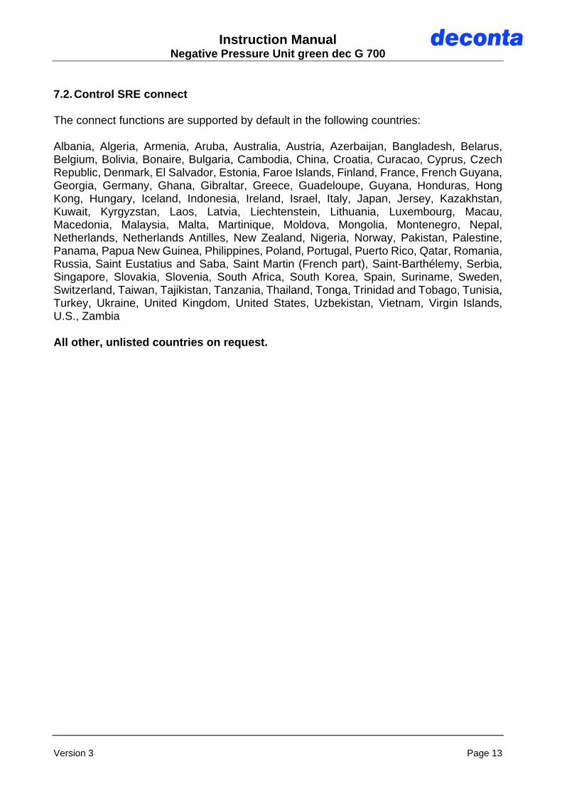
7.2.9. Service
deconta connect Allocate the device to a connect account (see point 7.2.2.). Maintenance Settings in this menu can only be made by qualified deconta service partners. Software packages See point 7.2.10.

Instruction Manual Negative Pressure Unit green dec G 700
Version 3 Page 23
System settings
Setting the day of the week and time. These values are displayed on the device display and are required for day / night settings. Data sent to the connect user account are displayed there in the set time zone (default UTC ± 0 = coordinated world time). By pressing the yellow button "Reset factory settings?” the red button "Reset factory settings!" is activated. By pressing on this red button, all settings are reset to factory settings! Language setting. Tapping the language button takes you to the menu for setting the display language. Selectable languages: English, German, French, Italian, Spanish, Japanese, Dutch and Portuguese.

Instruction Manual Negative Pressure Unit green dec G 700
Version 3 Page 24
7.2.10. Software packages Display of the booked options and the expiration date of the licenses.
Instruction Manual Negative Pressure Unit green dec G 700
Version 3 Page 25
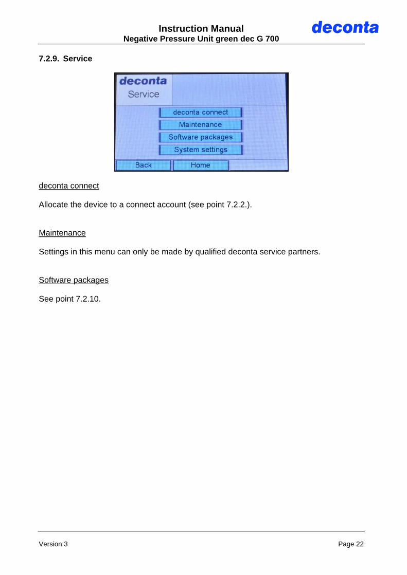
7.2.11. Device information Display of device information.
7.2.12. Alarms Alarms are visually displayed via a flashing icon on the main screen. At the same time, an acoustic signal sounds. There are 3 different icons: green checkmark: there is no alarm message.
yellow bell: there was an alarm that no longer exists but hasn’t been acknowledged yet.
red bell: there is an acute alarm message.

Instruction Manual Negative Pressure Unit green dec G 700
Version 3 Page 26
A submenu with details about alarms can be accessed by pressing the button with the green checkmark, the yellow or red bell. Alarms are displayed with a red button. After the removal of the fault, the alarm must be acknowledged by pressing on the respective button. Then the color changes to green.
Negative pressure:
- The set nominal value for the minimum negative pressure could not be reached. Volume flow:
- The set nominal value for the minimum volume flow could not be reached. High dust load:
- Message filter sensor for many particles within a short period of time. Low dust load:
- Message filter sensor for a few particles over a longer period. Filter pressure:
- with the buttons "-" and "+" the alarm value for the filter pressure can be continuously adjusted (yellow area in the display = filter needs to be replaced soon). The red area is set by factory. Filter change see point 8.2.1.

Instruction Manual Negative Pressure Unit green dec G 700
Version 3 Page 27
Stop dust sensor / Start dust sensor: - Turn on / off the dust sensors. Please note: when the sensors are switched off, the particle concentration in the exhaust air is not monitored! 7.2.13. Turn off the device
To switch off the device press on the red button "OFF"
In order to avoid an accidental switch-off, the process must be confirmed again.
The device shuts down and the power plug can be unplugged.

Instruction Manual Negative Pressure Unit green dec G 700
Version 3 Page 28
8. Maintenance Maintenance work, including changing/removing filters, may only be carried out by authorised persons wearing suitable protective clothing. The appliance must be completely disconnected from the power supply during all repairs and maintenance work. We expressly refer to possible additional regional and national regulations in the maintenance of the appliance technology. The air-conditioning systems (dust extraction unit, industrial vacuum cleaners and devices used for venting or negative pressurisation) must be serviced as required, at least once a year, and checked by a qualified technician. The test result shall be presented on request. 8.1. Information on filter change The frequency of the filter change depends on the degree of contamination of the filters. As the filter occupancy is increased (contamination of the filters), the air performance decreases. For filter monitoring, the filter pressure is shown in the display of the control system. If the display reaches the red area, please replace pre or bag filter first. If the display value drops by 100 Pascal or more, the unit can be operated again. If the value drops by less than 100 pascals, the HEPA filter must be replaced.
Important: Only use approved filters!
filter pressure

Instruction Manual Negative Pressure Unit green dec G 700
Version 3 Page 29
8.2. Filter change Attention: Contaminated filters must only be changed while observing all relevant safety
precautions Filter change only when the unit is switched off Use only approved filters Do not use residual fiber bonding agent on the unit Change of prefilter: • Carefully remove and dispose filters • Insert new filters
pre-filter

Instruction Manual Negative Pressure Unit green dec G 700
Version 3 Page 30
Change of bag filters: • Remove the pre-filters • Open the locks of the bag filters • Remove bag filters • Insert new bag filters, the bags should be vertical • Close the locks • Insert pre-filters
lock
Instruction Manual Negative Pressure Unit green dec G 700
Version 3 Page 31
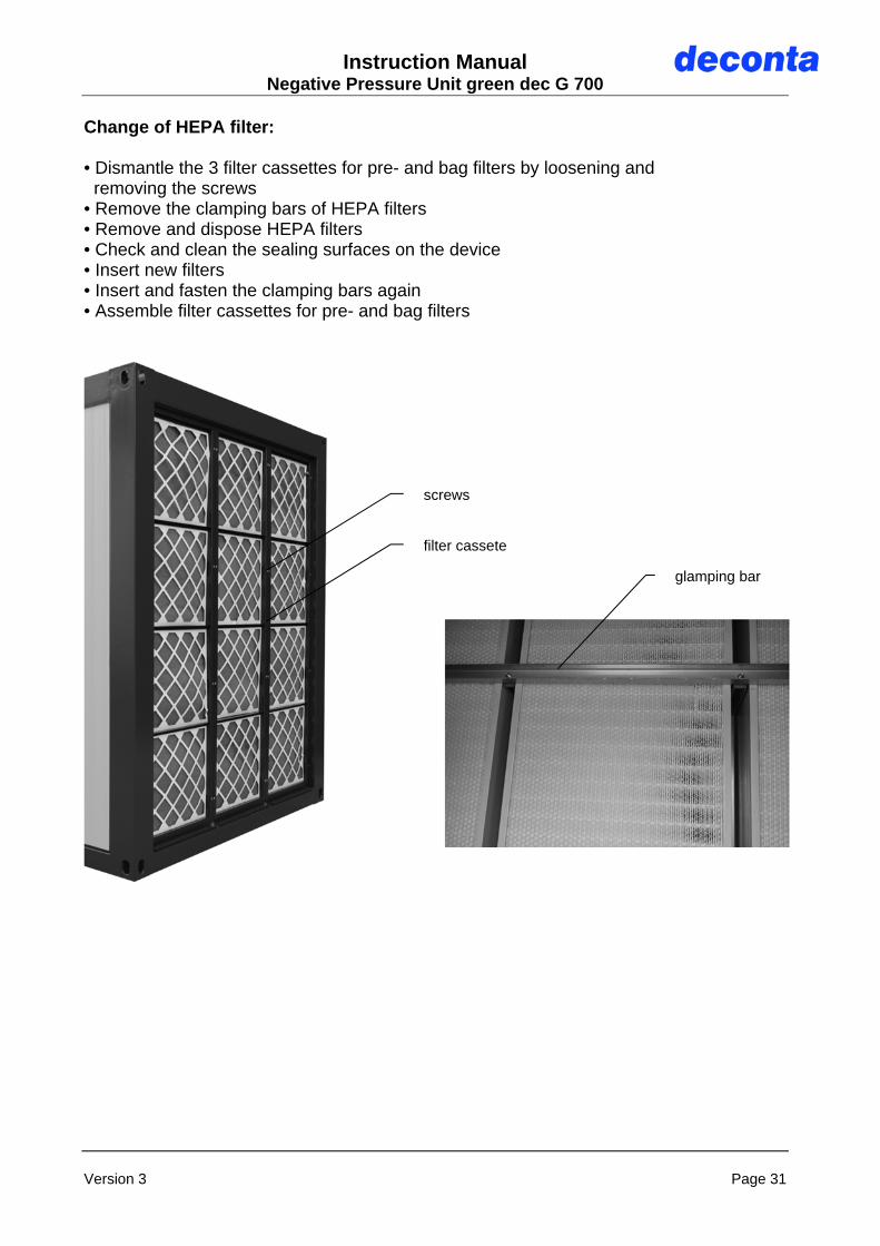
Change of HEPA filter: • Dismantle the 3 filter cassettes for pre- and bag filters by loosening and removing the screws • Remove the clamping bars of HEPA filters • Remove and dispose HEPA filters • Check and clean the sealing surfaces on the device • Insert new filters • Insert and fasten the clamping bars again • Assemble filter cassettes for pre- and bag filters
filter cassete
glamping bar
screws

Instruction Manual Negative Pressure Unit green dec G 700
Version 3 Page 32
9. Possible disturbances and their elimination
Fault Possible cause Elimination
Negative pressure too low
Pre- / intermediate or HEPA filter contaminated
Filter change as described in 8.2
Unit does not work Power source out of order Get the power source checked and repaired by a qualified technician
Unit does not work Defective components on the negative pressure unit
Have the unit repaired by deconta or a workshop authorised by deconta

Instruction Manual Negative Pressure Unit green dec G 700
Version 3 Page 33
10. Sound level measurements
Status: Outdoor area
Fan performance A1 A2 A3 A4 A5 B1 B2 B3 B4 B5
C1 D1
C2 D2
C3 D3
C4 D4
C5 D5
30 % 67 65 64 61 60 67 65 63 61 60 64 63 61 60 60
40 % 68 67 64 63 63 69 65 64 62 61 67 67 66 65 63
50 % 69 68 67 66 64 71 70 68 66 63 68 67 66 65 64
70 % 74 72 70 68 66 77 75 75 74 73 75 72 72 70 68
100 % 74 72 71 69 68 81 77 76 75 73 75 72 72 70 68
value in dB (A)

Instruction Manual Negative Pressure Unit green dec G 700
Version 3 Page 34
11. Declaration of Conformity
EC Declaration of Conformity acc. to Machinery Directive 2006/42 / EC Annex II 1.A
The manufacturer
deconta GmbH Im Geer 20 46419 Isselburg
hereby declares that the following product Product designation: green dec G 700
Type designation: G 700
Serial number: see type plate
Commercial designation: Negative Pressure Unit green dec G 700
Year of construction: see type plate Description: Negative Pressure Unit green dec G 700 complies with all applicable regulations of the above mentioned directive and the other applicable directives (hereafter), including the amendments applicable at the time of the declaration. The sole responsibility for issuing this Declaration of Conformity lies with the manufacturer. The protection objectives of the following EU directives have been complied with:
Low Voltage Directive 2014/35 / EU The following harmonised standards were applied:
EN 349:1993+A1:2008 Safety of machinery – minimum gaps to avoid crushing or parts of the human body
EN 50274:2002/AC:2009 Low-voltage switchgear and controlgear assemblies - Protection against electric shock - Protection against accidental direct contact with dangerous active parts
EN 50274:2002 Low-voltage switchgear and controlgear assemblies - Protection against electric shock - Protection against accidental direct contact with dangerous active parts
EN 60204-1:2006/A1:2009 Safety of machinery - Electrical equipment of machines - Part 1: General requirements (IEC 60204-1: 2005 / A1: 2008)
EN 60204-1:2006/AC:2010 Safety of machinery - Electrical equipment of machines - Part 1: General requirements (IEC 60204-1: 2005 (modified))
EN 60335-2-69:2012 Safety of household and similar electrical appliances - Part 2-69: Particular requirements for wet and dry vacuum cleaners (IEC 60335-2-69: 2012 (modified))
EN ISO 13850:2015 Machine safety - Emergency stop – Principles of design (ISO 13850: 2015)
EN ISO 13857:2008 Safety of machinery – Safety distances to prevent hazard zones being reached by upper and lower limbs (ISO 13857:2008)
Name and address of the person authorised to compile the technical documentation: Krolle, Christian Place: Isselburg Date: 03.12.2019 _______________________________ (Signature) Managing Director


![QBE at a glance UK · QBE Insurance Group Limited A– [negative] A– [negative] bbb [negative] QBE Insurance (Europe) Limited A– [negative] a [negative] QBE Re (Europe) Limited](https://static.fdocuments.in/doc/165x107/5fa8e28b58047158406a3b4f/qbe-at-a-glance-uk-qbe-insurance-group-limited-aa-negative-aa-negative-bbb.jpg)