
NEF 280 Use and maintenance - Cloudinary
26
1 ENGLISH NEF 280 (N67 MNT M28) USE AND MAINTENANCE SUMMARY Page FOREWORD . . . . . . . . . . . . . . . . . . . . . . . . . . . . . . . . . . . . . . . 2 ■ GENERAL INFORMATION . . . . . . . . . . . . . . . . . . . . . . . . . . . . 3 Warranty . . . . . . . . . . . . . . . . . . . . . . . . . . . . . . . . . . . . . . . . . . . 3 Spare Parts . . . . . . . . . . . . . . . . . . . . . . . . . . . . . . . . . . . . . . . . . 3 Responsibility . . . . . . . . . . . . . . . . . . . . . . . . . . . . . . . . . . . . . . . 3 Safety . . . . . . . . . . . . . . . . . . . . . . . . . . . . . . . . . . . . . . . . . . . . . . 3 Engine Data . . . . . . . . . . . . . . . . . . . . . . . . . . . . . . . . . . . . . . . . . 4 Engine Views . . . . . . . . . . . . . . . . . . . . . . . . . . . . . . . . . . . . . . . . 5 Labels. . . . . . . . . . . . . . . . . . . . . . . . . . . . . . . . . . . . . . . . . . . . . . 6 Personnel appointed to maintenance . . . . . . . . . . . . . . . . . . . . . 7 ■ USE . . . . . . . . . . . . . . . . . . . . . . . . . . . . . . . . . . . . . . . . . . . . . . . 8 Preliminary checks . . . . . . . . . . . . . . . . . . . . . . . . . . . . . . . . . . . 8 Engine stop . . . . . . . . . . . . . . . . . . . . . . . . . . . . . . . . . . . . . . . . . 8 Alarm status recognition . . . . . . . . . . . . . . . . . . . . . . . . . . . . . 10 Engine stop . . . . . . . . . . . . . . . . . . . . . . . . . . . . . . . . . . . . . . . . 11 Ensuring proper engine use . . . . . . . . . . . . . . . . . . . . . . . . . . . 11 Specific warnings . . . . . . . . . . . . . . . . . . . . . . . . . . . . . . . . . . . . 12 Refilling . . . . . . . . . . . . . . . . . . . . . . . . . . . . . . . . . . . . . . . . . . . 13 Running in . . . . . . . . . . . . . . . . . . . . . . . . . . . . . . . . . . . . . . . . . 14 ■ CHECKING AND MAINTENANCE . . . . . . . . . . . . . . . . . . . . 15 Accident prevention . . . . . . . . . . . . . . . . . . . . . . . . . . . . . . . . . 15 Checking frequency . . . . . . . . . . . . . . . . . . . . . . . . . . . . . . . . . 16 Instructions . . . . . . . . . . . . . . . . . . . . . . . . . . . . . . . . . . . . . . . . 17 How to proceed . . . . . . . . . . . . . . . . . . . . . . . . . . . . . . . . . . . . 18 Engine handling . . . . . . . . . . . . . . . . . . . . . . . . . . . . . . . . . . . . . 22 Waste disposal . . . . . . . . . . . . . . . . . . . . . . . . . . . . . . . . . . . . . 22 ■ ENGINE LEFT IDLE FOR THE LONG TERM . . . . . . . . . . . . . 23 Preparing the engine for long-term idle time . . . . . . . . . . . . . . 23 Putting into service an engine left idle for the longer term. . .24 ■ EMERGENCIES . . . . . . . . . . . . . . . . . . . . . . . . . . . . . . . . . . . . . 25
Transcript of NEF 280 Use and maintenance - Cloudinary

1
EN
GL
ISH
NEF 280 (N67 MNT M28)
USE AND MAINTENANCE
SUMMARY PageFOREWORD . . . . . . . . . . . . . . . . . . . . . . . . . . . . . . . . . . . . . . .2
■ GENERAL INFORMATION. . . . . . . . . . . . . . . . . . . . . . . . . . . .3Warranty. . . . . . . . . . . . . . . . . . . . . . . . . . . . . . . . . . . . . . . . . . .3Spare Parts . . . . . . . . . . . . . . . . . . . . . . . . . . . . . . . . . . . . . . . . .3Responsibility . . . . . . . . . . . . . . . . . . . . . . . . . . . . . . . . . . . . . . .3Safety . . . . . . . . . . . . . . . . . . . . . . . . . . . . . . . . . . . . . . . . . . . . . .3Engine Data . . . . . . . . . . . . . . . . . . . . . . . . . . . . . . . . . . . . . . . . .4Engine Views . . . . . . . . . . . . . . . . . . . . . . . . . . . . . . . . . . . . . . . .5Labels. . . . . . . . . . . . . . . . . . . . . . . . . . . . . . . . . . . . . . . . . . . . . .6Personnel appointed to maintenance . . . . . . . . . . . . . . . . . . . . .7
■ USE . . . . . . . . . . . . . . . . . . . . . . . . . . . . . . . . . . . . . . . . . . . . . . .8Preliminary checks . . . . . . . . . . . . . . . . . . . . . . . . . . . . . . . . . . .8Engine stop . . . . . . . . . . . . . . . . . . . . . . . . . . . . . . . . . . . . . . . . .8Alarm status recognition . . . . . . . . . . . . . . . . . . . . . . . . . . . . .10Engine stop . . . . . . . . . . . . . . . . . . . . . . . . . . . . . . . . . . . . . . . .11Ensuring proper engine use . . . . . . . . . . . . . . . . . . . . . . . . . . .11Specific warnings . . . . . . . . . . . . . . . . . . . . . . . . . . . . . . . . . . . .12Refilling . . . . . . . . . . . . . . . . . . . . . . . . . . . . . . . . . . . . . . . . . . .13Running in . . . . . . . . . . . . . . . . . . . . . . . . . . . . . . . . . . . . . . . . .14
■ CHECKING AND MAINTENANCE. . . . . . . . . . . . . . . . . . . .15Accident prevention . . . . . . . . . . . . . . . . . . . . . . . . . . . . . . . . .15Checking frequency . . . . . . . . . . . . . . . . . . . . . . . . . . . . . . . . .16Instructions . . . . . . . . . . . . . . . . . . . . . . . . . . . . . . . . . . . . . . . .17How to proceed . . . . . . . . . . . . . . . . . . . . . . . . . . . . . . . . . . . .18Engine handling . . . . . . . . . . . . . . . . . . . . . . . . . . . . . . . . . . . . .22Waste disposal . . . . . . . . . . . . . . . . . . . . . . . . . . . . . . . . . . . . .22
■ ENGINE LEFT IDLE FOR THE LONG TERM. . . . . . . . . . . . .23Preparing the engine for long-term idle time. . . . . . . . . . . . . .23Putting into service an engine left idle for the longer term. . .24
■ EMERGENCIES . . . . . . . . . . . . . . . . . . . . . . . . . . . . . . . . . . . . .25
NEF_280 Use and maintenance.fm Page 1 Sunday, November 21, 2004 11:58 AM

2
FOREWORDWe thank you for having selected IVECO MOTORS and extend our compliments for the engine selected.Before putting in place any operation involving the engine or its fit-tings and equipment, please read carefully the instructions set forth in this Manual; the related observance thereof ensures to you their perfect operation and enhanced duration over time.
The content of this Manual refers exclusively to the engine, in its standard configuration, and the illustrations are purely indicative. Some instructions are given describing the sequence of operations that enable the engine and/or its fittings and equipment to deliver expected performance. In certain cases, these depend upon the configuration of the controls and equipping of the craft in which the engine is installed; as and when differing from this Manual's content, reference should be made to the instructions issued by the Building Yard or contained in a specific manual.As set forth herein below, the information is correct at the date of publication.Constructor reserves the right to implement modifications without prior notice and at any time whatever, for technical or commercial cause or reason and, not least, to adapt the engines to ensure com-pliance with the legal requirements enacted in the differing nations.All and any liability is declined for errors and omissions, if any.
Please remember that the IVECO MOTORS Technical Support Network is there wherever you are with its professional skills and expertise.
NEF_280 Use and maintenance.fm Page 2 Sunday, November 21, 2004 11:58 AM
3
EN
GL
ISH
■ GENERAL INFORMATION
WARRANTYTo ensure the best engine efficiency and to exercise the IVECO MOTORS warranty, it is necessary to strictly follow the indications set forth in the herein Manual. The guarantee may lapse in the event of non-performance or incorrect performance of the above men-tioned indications.
SPARE PARTSUtilisation of IVECO MOTORS Original Spare Parts is an essential condition for maintaining he engine's original integrity.Use of non-original spare parts will make the warranty lapse and will also exempt IVECO MOTORS form any responsibility on the en-gine's life.
RESPONSIBILITYThe responsibility of the Manufacturer is subject to the execution of check-up and maintenance operations described in the herein Man-ual: the relevant execution shall be duly evidenced.Any extraordinary maintenance operation which may be necessary shall be executed by qualified engineers operating at authorized Technical Support Centres IVECO MOTORS Network.
SAFETYThe purpose of the following information is to draw your attention on the use of the engine in order to prevent injury or damages to people and things which may derive from incorrect behaviour or misconduct.
❑ The engines must be used exclusively for the applications speci-fied by the Manufacturer.
❑ Any manumission, change and/or use of non-original spare parts may compromise the engine's working efficiency and safe naviga-tion insofar; it is strictly prohibited to provide any change to the electric networks and to the wiring harness of the engine units.
❑ The engine has some parts in motion, other heated to high tem-perature and other parts containing pressurized fluids; its electri-cal equipment includes voltages and electric currents.
❑ Exhaust gas emissions from the engine are harmful.
❑ Engine handling must be executed by means of suitable hoisting equipment, using the specially provided ringbolts on the engine.
❑ The engine must not be started and used before safety require-ments prescribed for the craft on which it is installed are fully complied with; moreover, craft compliance with the laws and lo-cal legislation must be ensured as well.
❑ All operations required ensuring the best conditions of use and preservation of the engine must be executed only by qualified and experienced engineers, provided with IVECO MOTORS cer-tified tools.
Further recommendations concerning safety are reported in the "CHECKING AND MAINTENANCE" chapter following.
NEF_280 Use and maintenance.fm Page 3 Sunday, November 21, 2004 11:58 AM

4
ENGINE DATAThe technical acronym and the matrix number are reported on a plate applied, depending on the model, on different parts of the en-gine: fly-wheel cover carter, tappet cover, cooling liquid reservoir.
(*)Net Power to the fly-wheel in compliance with ISO 3046-1 Standard. Test conditions: 25 °C temperature, atmosphere p. 100 kPa; 30% relative humidity.
Acronym N67 MNT M28
Engine family NEF
Cycle 4-stroke Diesel
Number of cylinders available 6, on line
Stroke boring 104 x 132 mm
Total Swept Volume 6.700 cm3
Air feed Boost fed and post-cooled (TCA or TAA)
Ignition mode Direct with mechanical pump
Engine rotation direction (from fly-wheel side view) Anti-clock-wise
Dry Weight 595 kg
Electrical Equipment 12 V Rated voltage (24 V on request)
Accumulator/s - capacity 120 Ah or more - discharging current 900 A or more
Calibration available (*)
A1 206 kW (280 CV) @ 2800 rev/min
B 191 kW (260 CV) @ 2800 rev/min
C 147 kW (200 CV) @ 2800 rev/min
D 132 kW (180 CV) @ 2500 rev/min
W A R N I N G
It is strictly prohibited, warranty lapses as well as IVECO Motors Responsibility, to alter the above specified charac-teristics and, in particular, to change the ignition system
adjustment or the features of the electric system.
NEF_280 Use and maintenance.fm Page 4 Sunday, November 21, 2004 11:58 AM

5
EN
GL
ISH
N67 MNT M28 NEF ENGINE: right side view1. Exhaust gas discharge - 2. Turbo-compressor - 3. Heat exchanger for the engine cooling liquid/sea water - 4. Pipe fitting for cooling liq-uid heat release from the engine - 5. Oil filter - 6. Engine eyebolt for hoisting - 7. Cooling liquid filling cap - 8. Solenoid valve displacement - 9. Alternator - 10. Pipe fitting to the cooling liquid reservoir - 11. Cooling liquid input to the engine - 12. Caps for cooling liquid drainage - 13. Connection to the positive pole of the battery - 14. Electric starter - 15. Anode.
N67 MNT M28 NEF ENGINE: left side view1. Fuel filter - 2. Fuel input pipe fitting - 3. Cooling liquid expansion tank - 4. Oil priming pump - 5. Oil filling cap - 6. Oil level check rod - 7. Fuel output pipe fitting - 8. Engine eyebolt for hoisting - 9. Oil vapour filter - 10. Air filter - 11. Sea water pipe-fitting - 12. Ignition pump - 13. Sea water pump input - 14. Anode displacement - 15. Pul-ley fairing of auxiliary units - 16. Sea water drainage cap.
NEF_280 Use and maintenance.fm Page 5 Sunday, November 21, 2004 11:58 AM

6
LABELSThe yard organization shall ensure that the following warning labels are placed on the engines. The meaning of such labels is explained here below.Warning: Labels with exclamation mark highlight potential danger.
Hoisting point (of engine only)
Fuel filling cap (on tank, if available)
Lubrication oil filling cap
Lubrication oil level check rod
Danger: burnsExpulsion of pressurized heated water
Danger: burnsPresence of high temperature heated parts
Danger: firePresence of fuel
Danger: crash and hook-up to parts in motionPresence of fans, pulleys, belts and other.
NEF_280 Use and maintenance.fm Page 6 Sunday, November 21, 2004 11:58 AM

7
EN
GL
ISH
PERSONNEL APPOINTED TO MAINTENANCEAll necessary operations prescribed to ensure the best conditions to use and preserve the engine, and reported in the herein Manual, require preparation, competence and respect of the safety regula-tions and therefore must be executed by specially appointed per-sonnel, as indicated here following:
❑ Checking, to be performed by workshop staff or by the person using the craft.
❑ Periodical maintenance, to be performed by quali-fied staff appropriately equipped with tools and instru-ments, and duly protected; periodical maintenance is highlighted by the key symbol (see picture).
❑ Extraordinary maintenance, to be performed by qualified and skilled staff, endowed with specific tech-nical expertise and know-how, operating at authorized Technical Support Centres equipped with proper tooling and equipment. Extraordinary maintenance is highlighted by the key symbol (see picture).
The "Authorised Technical Support Centres" are those Centres forming part of the IVECO MOTORS Technical Support Network.
NEF_280 Use and maintenance.fm Page 7 Sunday, November 21, 2004 11:58 AM
8
■ USE
PRELIMINARY CHECKS Before starting the engine:
❑ Ensure that the sea water intake valve is open. Dry working of the sea water pump would cause irreparable deterioration of the internal rotor in few seconds.
❑ Check the level of the technical fuels (fuel, engine oil and cooling liquid).
ENGINE START
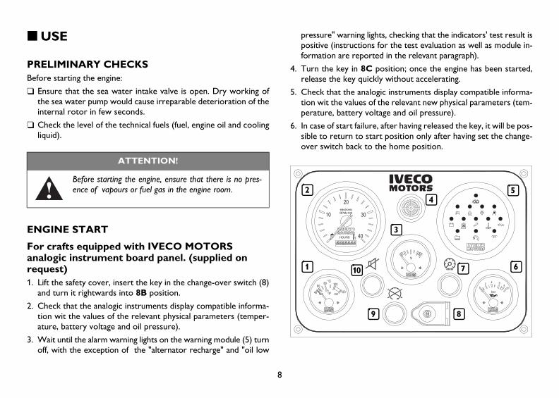
For crafts equipped with IVECO MOTORS analogic instrument board panel. (supplied on request)1. Lift the safety cover, insert the key in the change-over switch (8)
and turn it rightwards into 8B position.
2. Check that the analogic instruments display compatible informa-tion wit the values of the relevant physical parameters (temper-ature, battery voltage and oil pressure).
3. Wait until the alarm warning lights on the warning module (5) turn off, with the exception of the "alternator recharge" and "oil low
pressure" warning lights, checking that the indicators' test result is positive (instructions for the test evaluation as well as module in-formation are reported in the relevant paragraph).
4. Turn the key in 8C position; once the engine has been started, release the key quickly without accelerating.
5. Check that the analogic instruments display compatible informa-tion wit the values of the relevant new physical parameters (tem-perature, battery voltage and oil pressure).
6. In case of start failure, after having released the key, it will be pos-sible to return to start position only after having set the change-over switch back to the home position.
ATTENTION!
Before starting the engine, ensure that there is no pres-ence of vapours or fuel gas in the engine room.
1
2
3
45
67
89
10
NEF_280 Use and maintenance.fm Page 8 Sunday, November 21, 2004 11:58 AM

9
EN
GL
ISH
1. Cooling liquid temperature indicator - 2. Engine speed indicator and hour counter - 3. Voltmeter - 4. Acoustic warning device - 5. Alarm warning module - 6. Engine oil pressure indicator - 7. In-strument and instrument board lighting switch - 8. Key change-over switch for engine start/disconnection - 9. Engine disconnection switch - 10. Push button to exclude the acoustic warning device.
For crafts equipped with secondary IVECO MOTORS analogic instrument board panel (supplied on request).1. Enable the secondary board panel (fly bridge) to work,
turning the key change-over switch of the main board in 8B position (see procedures and checks set forth in the previ-ous paragraph).
2. Wait until the alarm warning lights on the warning module (4) turn off, with the exception of the "alternator recharge" and "oil low pressure" warning lights, checking that the indicators' test result is positive (instructions for the test evaluation as well as module in-formation are reported in the relevant paragraph).
3. Press the green push button (1) and hold it pressed until start has been completed, and then release it.
4. Check that the engine speed indicator displays reliable informa-tion.
1. Engine start switch - 2. Engine speed indicator - 3. Acoustic warn-ing device - 4. Alarm warning module - 5. Engine disconnection switch - 6. Push button to exclude the acoustic warning device.
For crafts equipped with customised instrument board panel (Not manufactured by IVECO MOTORS)The starting procedures described previously must be followed even in case the instrument board panel has been customised for the craft.
8A 8B
8C
1
2 43
5
6
NEF_280 Use and maintenance.fm Page 9 Sunday, November 21, 2004 11:58 AM

10
ALARM STATUS RECOGNITIONIVECO MOTORS on-board consoles are equipped with an elec-tronic module housing illuminated symbols and alarm memorization and timing interface circuits.The chart illustrates the module's dial and explains all illuminated symbols; some engine typologies and related equipment thereof make available certain functions, and only certain functions, as re-ferred to above.Owing to the differing technical options selected by the Yard, the foregoing may be modified.
1. Permitted maximum rotation operation in excess (on demand) - 2. Water present in fuel pre-filter - 3. Engine cooling fluid low level - 4. Alternator anomaly - 5. Clogged oil filter - 6. Clogged blow-by filter - 7. Pre-lubrication in progress - 8. Clogged air filter - 9. Clogged fuel filer 10. Cooling fluid high temperature - 11. Low oil pressure - 12. Pre-post warm up - 13. EDC failure.
Operation logicExcluding those relating to "Pre-lubrication", "Pre-post warm up" and "EDC failure", the efficiency test for all illuminated symbols is ac-tivated, for 5 seconds, by turning the change-over switch's key into position 8B; by pressing the relevant press-button, the warning horn produced during testing is inhibited.All alarm functions are inhibited during start-up phase and for 15 seconds immediately thereafter; after 15 seconds, each and every alarm status detected by the engine's sensors alights in flashing mode the related illuminated symbol and, at the same time, the warning horn. The warning horn may be silenced by pressing the rel-evant push-button. As a consequence thereof, the illuminated sym-bol turns from flashing to steady mode and alarm memorization remains until the engine is switched off.
12 12
11101334
5 6 8 9
7
NEF_280 Use and maintenance.fm Page 10 Sunday, November 21, 2004 11:58 AM
11
EN
GL
ISH
ENGINE STOPBefore switching off the engine, the engine should be kept in rota-tion for a few minutes at minimum and without load; this will reduce consistently the temperature of the engine parts and will help to avoid damaging thermal shocks.1. The engine is arrested by pressing the red push-button posi-
tioned on the IVECO MOTORS consoles or similar push-button as and when fitted in personalized consoles.
2. Should the engine be equipped with a "drop-out arrest" device (on demand), the IVECO MOTORS primary instrument board is arrested by turning the key-switch into the 8A rest position.
Restarting engine from the primary board:A. Turn the key-switch back to the rest position (8A) thereby dis-
enabling all functions performed by the on-board consolesB. Proceed as indicated under paragraph "ENGINE START-UP".
Restarting engine from the secondary board:A. Press the green push-button (1) until engine start-up, and then
release it.B. Make sure that the number rotation symbol provides plausible
indications.
ENSURING PROPER ENGINE USE❑ Once the engine has been started, do not prolong the start-up
command, insofar as this might damage the engine and the start-er.
❑ Do not remain docked while waiting for the engine to warm up. After start-up, start navigating at low speed; proper attainment
of running temperatures is obtained with the engine at running conditions other than minimum running conditions and with lim-ited engine load.
❑ Do not continue minimum running conditions for a long time as this heightens the release of hazardous emissions by the engine and does not assure best performance.
❑ Upward and downward curved engine running conditions should be attained gradually in order to assure regular combustion and better engine operation as a whole; sudden and abrupt accelera-tion may generate exhaust fumes.
❑ As and when the craft is new, maximum rotation conditions at-tained by the engine should be more than 50 revolutions/min. vis-à-vis engine's maximum power conditions, as detected when nav-igating a craft at full load and with proper propeller.
❑ Maximum cruising conditions should be maintained at a value in-ferior to approximately 10% of max. power conditions.
❑ During navigation, make sure that:• the temperature of the engine's cooling fluid does not exceed
the alarm thresholds, and;• the oil pressure remains within normal values.
Should the temperature be deemed to be excessive, reduce speed and return to the harbor to check the sea-water circuit's status; also check. The following should be checked:a) voltage of water pump command belts and alternator;b) thermostat operation; andc) heat exchanger cleanliness
NEF_280 Use and maintenance.fm Page 11 Sunday, November 21, 2004 11:58 AM
12
SPECIFIC WARNINGSCooling fluid circuitOnce the engine has warmed up, established within the cooling cir-cuits is a pressure having the capability to expel hot liquid with ex-treme violence thereby giving rise to the risk of burns.
Lubrication circuitShould the "low oil pressure" (11) warning light on the ALLARMS AND SIGNALLING MODULE alight, the engine should be arrested. With the craft running under safety conditions, check the oil level and, where applicable, add oil.Should the warning light continue to stay alight, call an authorized Technical Support Centre.
Exhaust and suction circuitInspect regularly the air suction circuit for cleanliness. The mainte-nance frequency schedules set forth below vary according to how the engine is used.
Fuel circuitTry not to use the engine when its fuel tank is in reserve; operating in reserve might cause the formation of condensation or air suction thereby arresting the engine.
Starter electric systemCheck periodically the batteries, especially in the winter season, for cleanliness and efficiency, controlling and topping up the batteries as recommended under the heading "CHECKING AND MAINTE-NANCE".
ATTENTION!
Where necessary, the cooling liquid float chamber's refu-elling plug should be removed when, and only when, the engine is cold.
ATTENTION!
In order to avoid fumes and hazardous releases to the air, examine the exhaust circuit to ensure that it is neither ob-structed nor damaged.
ATTENTION!
Maximum attention is required during refuelling in order to ensure that no liquid or solid pollutants enter into the tank; of particular note, do not smoke or alight flames
during refuelling.
ATTENTION!
The batteries contain an acid solution, which cauticizes skin and corrodes garments; when checking the batteries, please wear protective clothing, gloves and glasses; do not
smoke or alight flames near to them and, not least, ensure that the rooms in which the batteries are housed are properly ventilated.
NEF_280 Use and maintenance.fm Page 12 Sunday, November 21, 2004 11:58 AM

13
EN
GL
ISH
REFILLING
.1) Use 50% PARAFLUE 11 and 50% water also in the summer sea-
son in order to ensure cooling circuit optimum protection. On condition that international standard SAEJ 1034 compliance is ensured, a similar product may be employed in alternative to PARAFLU 11.
2) The quantity indicated is the quantity needed for periodical oil replacement.
3) Use lubricants that comply with the following international standards:• for supercharged engines: ACEA E3-E5 (MIL. L 2104E/F)• for non-supercharged engines: ACEA 32 (MIL. L 2104/F)Acceptable oil consumption: not more than 0.2% of fuel con-sumption.
4) With atmospheric temperature below 0° C, use winter fuel.
RefuellingUse only normally commercialized diesel-oil (EN 590 Standard). Fuel additives should be avoided. Fuel additives should be used for engine performances only.Drum or jerry-can refuelling may cause diesel-oil pollution, with re-sultant damage to the fuel-injection system; where applicable, filter adequately or sediment impurities prior to refuelling.
Diesel-oil in low temperaturesIn the instance of low temperatures, diesel-oil fluidity may be inad-equate due to paraffin solidification thus giving rise to filter clogging risk. EN 590 Standard envisages the employment of diverse diesel-oil classes at low environmental temperatures.
Entrusted entirely to Oil Companies is compliance with the Stand-ard calling for the distribution of fuel in accordance with the geo-graphic and weather conditions prevailing in the differing countries.
Parts to be refilled Quantity Product (liters kg.)
Cooling ≈24.5 - PARAFLU Circuit 11 and 50% water (1)
Engine oil 16.5 15 Lubricating oil (3)
pan and oil filter ACEA E3 - E5 (3)
(total capacity)
Engine oil pan only: • at minimum level 9 8 • at maximum level (2) 14.5 13.2
Fuel - - Diesel-oil (4)
Tank
W A R N I N G
Should fuel with a sulphur percentage in excess of 0.5% or ACEA E2 (MIL. L 2104E/F) be used in supercharged engines, engine oil must be changed every 300 hours.
NEF_280 Use and maintenance.fm Page 13 Sunday, November 21, 2004 11:58 AM
14
Reversing gear oil refillingInformation as to the quantity and type of oil to be employed in the reversing gear can be found in the manual supplied by Manufacturer.
RUNNING INOwing to the modern technologies applied when constructing the engines, no particular running in procedures are required. Howev-er, use of the engine for long periods of time at high power is not recommended for the first 50 hours.
NEF_280 Use and maintenance.fm Page 14 Sunday, November 21, 2004 11:58 AM

15
EN
GL
ISH
■ CHECKING AND MAINTENANCE
As reported hereunder, engine checking and maintenance requires preparation, competence and compliance with Safety Standards; as a consequence thereof, engine checking and maintenance should be carried out, as set out below, by specifically assigned personnel:
❑ Engine checking, to be performed by workshop staff or by the person using the craft.
❑ Periodical maintenance, to be performed by qualified staff ap-propriately equipped with tools and instruments, and duly pro-tected; periodical maintenance is highlighted by the key symbol.
❑ Extraordinary maintenance, to be performed by qualified and skilled staff, endowed with specific technical expertise and know-how, operating at authorized Technical Support Centres equipped with proper tooling and equipment.
"Authorized Technical Support Centres" are those Centres forming part of the IVECO MOTORS Technical Support Network.
ACCIDENT PREVENTION❑ Always wear accident prevention shoes and overalls.
❑ Do not wear loose clothing, rings, bracelets and/or necklaces when standing near to the engines or moving engine parts.
❑ Wear protective gloves and glasses when:• topping up batteries with acid solution;• refilling with inhibitors or anti-freeze, and;• replacing or refilling with lubricating oil (hot engine oil may
cause burns. We recommend that this should be replaced or refilled when, and only when the temperature of the oil is less than 50°C).
❑ Wear glasses using pressurized air (maximum air pressure em-ployed for cleaning must not exceed 200 kPa (2 bar, 30 psi, 2 kg/cm2).
❑ Wear a protective helmet when working in places with over-hanging loads or with head-height installations.
❑ Use protective hand-cream.❑ Remove and change immediately wet overalls.❑ Always keep the engine clean, eliminating any spots of oil, diesel
oil and/or cooling fluids.❑ Place greasy rags in flame-retardant cases.❑ Do not leave any cloths or rags on the engine.❑ Use proper and safe containers to store used oil.❑ Once overhauled and repaired, appropriate measures should be
taken to arrest air suction should starter be out-of-revolution.
ATTENTION!
Avoid performing maintenance in the presence of electric voltage: in all cases, check installation's effective earthing. When regulating the installation, make sure that your hands
and feet are dry and stand on insulating footboards.
ATTENTION!
Unless you are fully qualified and sufficiently informed, do not try to make repairs. Always follow the instructions contained in the Repair & Overhaul Manuals. In the absence thereof,
please contact Vendor or IVECO MOTORS Network qualified staff mem-bers.
NEF_280 Use and maintenance.fm Page 15 Sunday, November 21, 2004 11:58 AM

16
CHECKING FREQUENCY
As discussed below, the following checks should be carried out by authorized Technical Support Centre maintenance crews.As indicated in the form of engine operating hours, maintenance fre-quency compliance is required.The more appropriate space of time elapsing from one maintenance intervention to another shall be indicated by the maintenance crew on a basis consistent with engine operating conditions and usage.
Checks (to be carried out Frequency when engine is not left idle)
Oil pan oil level check daily
Reversing gear oil level check daily
Cooling fluid level check daily
Fuel pre-filter check for the presence of water daily
Battery (1) electrolytic solution level check six-monthly
Routine maintenance Frequency
Air filter cleaning (1) 300 hours
Zinc anode corrosion checking (5) 300 hours
Oil pan oil replacement (2) (3) ≈ 600 hours
Oil filter replacement (2) (3) 600 hours
Fuel filter replacement (2) (4) 600 hours
Fuel pre-filter replacement (2) (4) 1200 hours
Rotating sea-water pump inspection (2) 1200 hours
Equalizer/Valve gap regulation 3000 hours
Reversing gear oil replacement (6) -
Extraordinary maintenance Frequency
Turbo-compressor cleaning (where applicable) 1200 hours
Water/Air exchanger cleaning (2) 1200 hours
Water/Water exchanger cleaning (2) 1200 hours
Reversing gear water/oil exchanger cleaning (where applicable) (2) 1200 hours
Alternator/Water pump belt command replacement 1200 hours
NEF_280 Use and maintenance.fm Page 16 Sunday, November 21, 2004 11:58 AM

17
EN
GL
ISH
1) Frequency depends upon environmental conditions and product effectiveness.After long periods of engine idle time, check prior to start-up.
2) To be performed every year even if number of operating hours envisaged is not reached.
3) Frequency applicable to ACEA E3-E5 and API CH 4.Standards compliant lubricants.Frequency reduced to 300 hours for ACEA E3-E5 and API CH 4 Standards compliant lubricants.Should fuel having a sulphur percentage in excess of 0.5% be used, the engine oil replacement span is halved.
4) Maximum period relating to the employment of good quality fuel; this is reduced in relation to fuel contamination and alarms sig-nalling clogging and the presence of water in the pre-filter. At low temperatures, diesel-oil fluidity may become inadequate due to paraffin separation with resultant risk of filter clogging.Clogging signalling calls for filter replacement; the presence of water calls for drainage using the specific drain plug. Should the warning light remain alight, replace pre-filter (further information can be found under the heading "CHECKING AND MAINTE-NANCE").
5) Zinc corrosion limit is equal to 50%; should such limit be exceed-ed, this must be replaced.
6) Please refer to reversing gear Manufacturer's Manual.
INSTRUCTIONS1. Do not disconnect supply to the batteries while engine is in mo-
tion.
2. Do not arc weld near to the engine without having first removed its electric cable.
3. After every maintenance intervention requiring battery discon-nection, make sure that the terminals are once again well clamped on the poles.
4. Do not use battery chargers to start engine.
5. Disconnect electrically the battery/batteries from the board net-work during its/their recharging.
6. Do not paint the engine equipment sets, components and elec-tric components.
7. Disconnect electrically the battery/batteries prior to any electri-cal intervention whatever.
8. Contact the Yard before installing any onboard electronic equip-ment (two-way radio sets, echo-sounders, etc.).
NEF_280 Use and maintenance.fm Page 17 Sunday, November 21, 2004 11:58 AM
18
HOW TO PROCEED
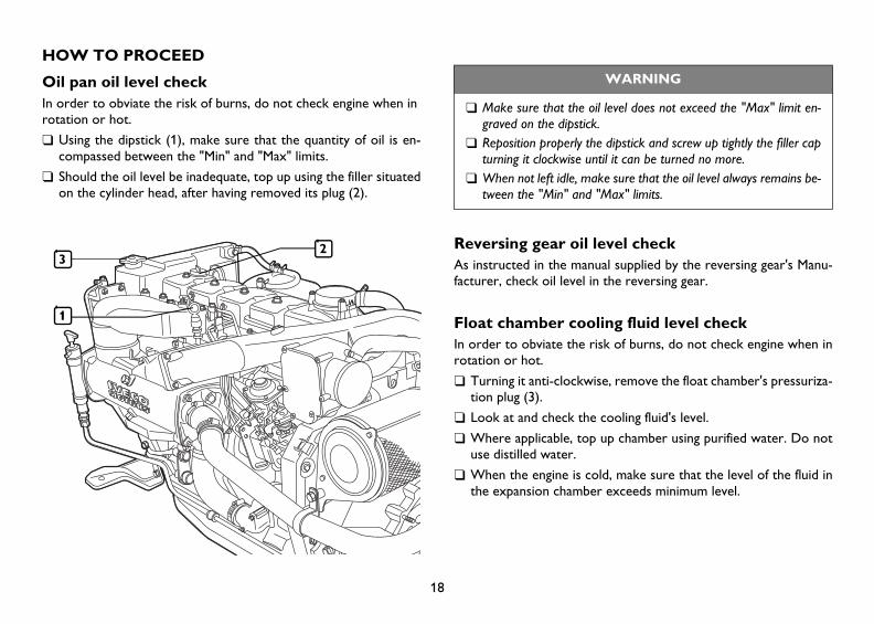
Oil pan oil level checkIn order to obviate the risk of burns, do not check engine when inrotation or hot.
❑ Using the dipstick (1), make sure that the quantity of oil is en-compassed between the "Min" and "Max" limits.
❑ Should the oil level be inadequate, top up using the filler situated on the cylinder head, after having removed its plug (2).
Reversing gear oil level checkAs instructed in the manual supplied by the reversing gear's Manu-facturer, check oil level in the reversing gear.
Float chamber cooling fluid level checkIn order to obviate the risk of burns, do not check engine when in rotation or hot.
❑ Turning it anti-clockwise, remove the float chamber's pressuriza-tion plug (3).
❑ Look at and check the cooling fluid's level.
❑ Where applicable, top up chamber using purified water. Do not use distilled water.
❑ When the engine is cold, make sure that the level of the fluid in the expansion chamber exceeds minimum level.
WARNING
❑ Make sure that the oil level does not exceed the "Max" limit en-graved on the dipstick.
❑ Reposition properly the dipstick and screw up tightly the filler cap turning it clockwise until it can be turned no more.
❑ When not left idle, make sure that the oil level always remains be-tween the "Min" and "Max" limits.
3
1
2
NEF_280 Use and maintenance.fm Page 18 Sunday, November 21, 2004 11:58 AM

19
EN
GL
ISH
Pre-filter check for the presence of waterDue to the high risk of refuelling being polluted by chemical agents and water, the check should be performed even when no alarm is signalled on the board panel.Check should be performed with engine at rest.
❑ Place a case or tray under the pre-filter so that the fluids can be collected.
❑ Unscrew the tap plug (1) situated on the lower part of the pre-fil-ter; in on-demand equipment, the plug comprises the sensor de-tecting the presence of water in diesel-oil.
❑ Drain fluid until only diesel-oil is detected.
❑ Screw plug completely back by hand.
❑ Get rid of drained fluids in ac-cordance with currently prevail-ing waste disposal laws and regulations.
Battery electrolytic solution level checkCheck should be performed once batteries are placed on a horizon-tal plane.
❑ Visually check that the liquid level is between the "Min." and "Max." references. If there are no references, check that the liq-uid covers the lead plates inside the elements.
❑ Top up the elements whose level is underneath the minimum with distilled water only.
❑ Contact specialised workshop personnel if the battery needs re-charging.
❑ During the procedure, check that the battery terminal and clamps are clean, tight and protected by a coat of Vaseline
Some batteries are equipped with a single inspection cap lid. Lever as shown in the figure to access the elements.
WARNING
❑ Batteries contain highly caustic and corrosive sulphuric acid; when top-ping up, wear protective gloves and glasses. Where possible, we rec-ommend that the check should be performed by specifically assigned staff members.
❑ When checks are being performed, do not smoke or alight flames near the batteries. Of particular note, make sure that the rooms in which the checks are being performed are properly ventilated.
❑ Should the voltage be lower than 21V (for installation at nominal 24V) or 10V (for installation at 12V), the batteries and the electric recharg-ing system must be checked for serviceability.
1
NEF_280 Use and maintenance.fm Page 19 Sunday, November 21, 2004 11:58 AM
20
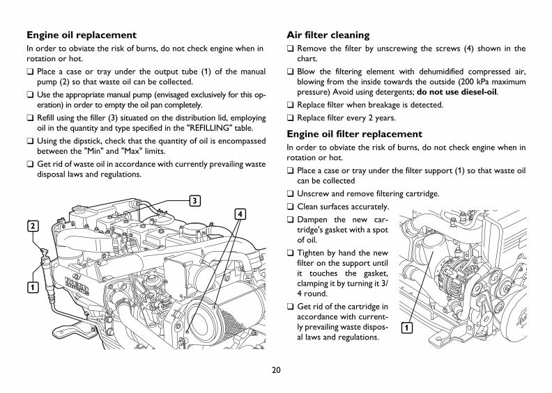
Engine oil replacementIn order to obviate the risk of burns, do not check engine when inrotation or hot.
❑ Place a case or tray under the output tube (1) of the manual pump (2) so that waste oil can be collected.
❑ Use the appropriate manual pump (envisaged exclusively for this op-eration) in order to empty the oil pan completely.
❑ Refill using the filler (3) situated on the distribution lid, employing oil in the quantity and type specified in the "REFILLING" table.
❑ Using the dipstick, check that the quantity of oil is encompassed between the "Min" and "Max" limits.
❑ Get rid of waste oil in accordance with currently prevailing waste disposal laws and regulations.
Air filter cleaning❑ Remove the filter by unscrewing the screws (4) shown in the
chart.
❑ Blow the filtering element with dehumidified compressed air, blowing from the inside towards the outside (200 kPa maximum pressure) Avoid using detergents; do not use diesel-oil.
❑ Replace filter when breakage is detected.
❑ Replace filter every 2 years.
Engine oil filter replacementIn order to obviate the risk of burns, do not check engine when in rotation or hot.
❑ Place a case or tray under the filter support (1) so that waste oil can be collected
❑ Unscrew and remove filtering cartridge.
❑ Clean surfaces accurately.
❑ Dampen the new car-tridge's gasket with a spot of oil.
❑ Tighten by hand the new filter on the support until it touches the gasket, clamping it by turning it 3/4 round.
❑ Get rid of the cartridge in accordance with current-ly prevailing waste dispos-al laws and regulations.
3
1
24
1
NEF_280 Use and maintenance.fm Page 20 Sunday, November 21, 2004 11:58 AM

21
EN
GL
ISH
Fuel filter replacement❑ Unscrew the filter and remove it.
❑ Make sure that the new filter's performance meets the needs of the engine (e.g., on a comparative basis with the replaced filter's performance).
❑ Dampen the new filter's gasket with diesel-oil or engine oil. In or-der to obviate the risk of introducing hazardous impurities in the circuit and in the fuel-injection system, do not fill the new filter before it has been placed on the support.
❑ Tighten by hand the new filter on the support until it touches the gasket, clamping it by turning it 3/4 round.
N.B.: Air may be blown out by loosening the diesel-oil delivery pipe's connector to the engine
Fuel pre-filter replacement❑ Unscrew and remove pre-filter.
❑ Make sure that the new filter's performance meets the needs of the engine (e.g., on a comparative basis with the replaced filter's performance).
❑ Dampen the new filter's gasket with diesel-oil or engine oil.
❑ Tighten by hand the new filter on the support until it touches the gasket, clamping it by turning it 3/4 round.
❑ Operate the manual pump situated on the pre-filter's support un-til the feeding circuit is refilled.
❑ Start the engine and keep it rotating at minimum for a few min-utes until all residual air has been removed.
N.B.: Air may be blown out by loosening the diesel-oil delivery pipe's connector to the engine.
NEF_280 Use and maintenance.fm Page 21 Sunday, November 21, 2004 11:58 AM

22
Equalizer/Valve gap regulationReversing gear oil replacementTurbo-compressor cleaningWater/Air exchanger cleaningWater/Water exchanger cleaningReversing gear water/oil exchanger cleaningAlternator/Water pump belt command replacementRotating sea-water pump inspection
ENGINE HANDLINGThe engine should be disembarked and successively re-embarked exclusively by authorized Technical Support Centre crews.When lifting the engine only, use the eyelets indicated herein un-der the heading "ENGINE PLAN VIEWS" and labelled appropriately on the engine.The engine should be lifted by a rocker arm that holds in parallel the wire ropes supporting the engine, and using, at the same time, all of the eyelets made available; the use of one eyelet only is not permit-ted.The rage and size of the engine's lifting system should be consistent with the engine's weight and dimension; make sure that nothing in-terferes with the lifting system and the engine's gears.Do not lift the engine before having removed the transmission gears coupled thereto.
WASTE DISPOSALComposing the engine are parts and elements, which, if released to the environment, might create ecological hazards.The materials listed below should be delivered to properly author-ized hazardous waste collection Centres; enacted laws currently prevailing around the globe punish transgressors severely:❑ starter batteries❑ waste lubricating oil❑ water mixed with anti-freeze❑ filters❑ ancillary cleaning material (e.g., greasy rages or rags soaked in fuel).
WARNING
The operations listed below should be carried out exclu-sively by Technical Support Centre maintenance crews. The related modalities thereof are set out in the Repair
and Overhaul Technical Manuals.
NEF_280 Use and maintenance.fm Page 22 Sunday, November 21, 2004 11:58 AM

23
EN
GL
ISH
■ ENGINE LEFT IDLE FOR THE LONGER TERM
PREPARING THE ENGINE FOR LONG-TERM IDLE TIMEShould the engine not be expected to be used for more than two months straight, the following must be performed on a six-monthly basis in order to avoid any parts inside the engine and/or certain fuel injector components oxidizing:
1. After warming up the engine, drain out the lubricating oil from the oil pan.
2. Pour 30/M protective oil (or, alternatively, MIL 2160B type 2 compliant oil) into the engine, up to the "minimum" oil level marked on the dipstick. Turn on the engine and keep it rotating for about 5 minutes.
3. Drain the injection circuit, filter and injection pump ducts from fuel.
4. Having excluded injection system operation, joint the fuel circuit to a tank containing CFB protective liquid (ISO 4113) and help the fluid to flow out by exerting pressure on the circuit and drag-ging in rotation the engine for about 2 minutes. This may then be terminated by polarizing directly terminal 50 of the electric start-er with positive current equal to the system's rated current, us-ing the applicable voltage conductor.
5. During the dragging discussed earlier, spray 30/M protective oil in a quantity approximating 70 g. (10g. per displacement litre) over the turbo-compressor's suction head.
6. Obscure appropriately with plugs, or seal with adhesive tape, all engine vents and aeration, draining and suction vents.
7. Drain from the crankcase any residual 30/M protective oil, which can be used again for another 2 engine preparations.
8. Affix "ENGINE WITHOUT OIL" labels to the engine and board console.
9. As and when not mixed with anti-freeze and anti-corrosives, drain out the cooling fluid, affixing labels confirming that the fluid has been drained.
Should you wish to protect the external parts of the engine, spray unpainted metal parts, such as the flywheel, pulleys and other, with OVER 19 AR protective fluid, without spraying belts, connection ca-bles and electric equipment.
NEF_280 Use and maintenance.fm Page 23 Sunday, November 21, 2004 11:58 AM
24
PUTTING INTO SERVICE AN ENGINE LEFT IDLE FOR THE LONGER TERM1. Drain out any residual 30/M protective oil from the oil pan.
2. As prescribed, pour into the engine lubricating oil of the type and in the quantity shown in the "REFUELLING" table.
3. Drain the CFB protective fluid from the fuel circuit terminating the operations as indicated earlier under the heading "PREPARING THE ENGINE FOR LONG-TERM IDLE TIME", paragraph 3.
4. Remove the plugs and/or seals from the engine vents and aera-tion, draining and suction vents restoring normal working condi-tions. Connect the turbo-compressor's suction head to the air filter.
5. Joint the fuel circuits to the craft's tank terminating the opera-tions as indicated earlier under the heading "PREPARING THE ENGINE FOR LONG-TERM IDLE TIME", paragraph 4. During refuelling, joint the fuel's feedback tube to a fluid collector in or-der to avoid any residual CFB protective fluid flowing into the craft's tank.
6. Check and refuel the engine with cooling fluid as prescribed.
7. Turn on the engine and keep it rotating until running smoothly at minimum.
8. Check that the indications shown by the instruments fitted in the board console (consoles) are plausible and that there are no alarm signals.
9. Turn off the engine.
10.Remove the "ENGINE WITHOUT OIL" labels from the engine and from the board console.
NEF_280 Use and maintenance.fm Page 24 Sunday, November 21, 2004 11:58 AM
25
EN
GL
ISH
■ EMERGENCIES
As created and built in accordance with safety standards, and on a basis consistent with the instructions set forth herein in conjunction with the indications reported on the engine labels, the person using the craft operates under safety conditions.Should improper use or conduct cause accidents, please call imme-diately for the assistance of qualified first-aid personnel.In the event of emergency and pending the arrival of rescue squads, reference should be made to the following:
FirePut out the fire using the fire-fighting appliances fitted on board as re-quired by the competent Authorities (mandatory on-board fire-pre-vention appliances required by enacted and currently prevailing safety laws and regulations).
Burns1. Put out the flames on the garments worn by the victim by:
• pouring water on the victim's garments;• using a powder fire extinguisher, trying not to spray the victim's
face;• cover or role the victim on the floor.
2. Do not pull off any pieces of clothing sticking to the victim's skin.
3. In the case of burns caused by fluids, remove the victim's gar-ments drenched in hot fluids.
4. Cover the burn with anti-burn dressing or sterile bandage.
Carbon monoxide (CO) intoxicationThe carbon monoxide contained in the engine's exhaust gas is odourless and dangerous because it causes intoxication and, not least, forms and explosive mixture when mixed with air.In closed rooms and premises, carbon monoxide is very dangerous because it can reach critical concentration in a very short time.As and when rescuing an intoxicated person in a closed room:
1. Ventilate immediately the room in order to reduce the concen-tration of gas.
2. When entering the room, the rescuer must hold his breath, not turn on any lights, or press electric bells or telephones in order to avoid explosions.
3. Help the victim out the room taking him or her to a well venti-lated room or outside in the open air, lying the victim on his or her side if unconscious.
Electric shocksThe engine's 12V or 24V electric system does not give rise to the risk of electric shocks. However, in the instance of a short circuit caused, for example, by a metal tool, the risk of burns might arise due to the overheating of the object touched by the electric cur-rent. In this instance:
1. Remove the object that caused the short circuit using means that ensure adequate thermal insulation.
2. Where applicable, turn off the cut-out switch in order to cut off the electricity supply.
NEF_280 Use and maintenance.fm Page 25 Sunday, November 21, 2004 11:58 AM

26
Injuries and fracturesThe broad array of case studies and the specificity of the steps and measures to be taken call necessarily for medical aid.
1. In the instance of injuries with loss of blood, compress the wound from the outside until rescuers arrive.
2. In the instance of suspected fracture, do not move the part of the body concerned and transfer the injured person with extreme caution, and only in the case of extreme need.
CausticizationSkin causticization is caused by coming into contact with substances with high acidity or basicity content.Typically, causticization suffered by electric system maintenance crews is caused by battery acid leakage; in this instance:
1. Remove the garments drenched in the caustic substance.
2. Wash abundantly with running water, trying not to wet any parts not affected.
In the instance of eye causticization, whether caused by coming into contact with battery acid or lubricant oil or diesel oil: wash the eye with water for 20 minutes at least holding the eyelid open so that the water flows over the eyeball (help the eyewash by moving the eye in all directions).
NEF_280 Use and maintenance.fm Page 26 Sunday, November 21, 2004 11:58 AM