Neexxyyss33 uBBSSBB iSSuppppoorrtt FFilleess ffoorr...
14
Nexys3 BSB Support Files for AXI-based EDK 13_2..14_4 Designs Revision: March 17, 2013 1300 NE Henley Court, Suite 3 Pullman, WA 99163 (509) 334 6306 Voice | (509) 334 6300 Fax www.digilentinc.com page 1 of 14 Copyright Digilent, Inc. All rights reserved. Other product and company names mentioned may be trademarks of their respective owners. Overview These files will integrate Base System Builder (BSB) support for the Nexys3 Spartan-6 field programmable gate array (FPGA) Development Board with tools from the Xilinx Embedded Development Kit (EDK). These support files include board definition files and Digilent custom core support files that will help customers create AXI-based MicroBlaze embedded designs in the BSB. Operators can use these files to enable the BSB to create Platform Studio projects initialized with properly configured cores for controlling on-board peripherals. This reference describes the procedures and important information for: I. Utilizing the BSB Support Files II. Creating a Base System using BSB Wizard III. Making Connections for the Custom Cores I. Utilizing the BSB Support Files Before beginning to use the BSB Support Files, Digilent recommends that customers first uninstall any older versions of the AXI IPCore support files and download the support files for the most current version of the Xilinx EDK labeled 1_34. Users that employ Digilent products may already have the most current version of the Digilent AXI IPCore Support Files. These files have to be installed only once per EDK version and are valid for all applicable Digilent boards. For instance, if customers have installed another Digilent board (e.g. the Atlys) the Digilent AXI IPCore Support Files will provide the current version of EDK to support all other Digilent boards. Users must follow steps 1-1 through 1-6 to use supported Xilinx BSB peripherals. 1-1. Install the Digilent AXI IPCore Support Files by running the batch file “..\Digilent_AXI_IPCore_Support_v_1_34\inst_uninst.bat” and then following the on- screen instructions. 1-2. Begin by creating the Base System using the Base System Builder Wizard. See section II “Creating a Base System using BSB Wizard” for more details. Note: Table one outlines the peripherals Xilinx BSB currently supports. To use the custom core supported peripherals go to “System Assembly View” and follow steps 1-3 through 1- 6. 1-3. Make the AXI clock connections for each custom core. For details on making AXI clock connections refer to the section 3a “Connecting AXI Clock Signals to the custom cores.” 1-4. Connect the external ports for each custom core. Refer to section 3b “Making external port connections for the custom cores” for more details
Transcript of Neexxyyss33 uBBSSBB iSSuppppoorrtt FFilleess ffoorr...

NNeexxyyss33 BBSSBB SSuuppppoorrtt FFiilleess ffoorr
AAXXII--bbaasseedd EEDDKK 1133__22....1144__44 DDeessiiggnnss
Revision: March 17, 2013 1300 NE Henley Court, Suite 3
Pullman, WA 99163 (509) 334 6306 Voice | (509) 334 6300 Fax
www.digilentinc.com page 1 of 14
Copyright Digilent, Inc. All rights reserved. Other product and company names mentioned may be trademarks of their respective owners.
Overview These files will integrate Base System Builder (BSB) support for the Nexys3 Spartan-6 field
programmable gate array (FPGA) Development Board with tools from the Xilinx Embedded
Development Kit (EDK). These support files include board definition files and Digilent custom
core support files that will help customers create AXI-based MicroBlaze embedded designs
in the BSB.
Operators can use these files to enable the BSB to create Platform Studio projects
initialized with properly configured cores for controlling on-board peripherals. This reference
describes the procedures and important information for:
I. Utilizing the BSB Support Files II. Creating a Base System using BSB Wizard III. Making Connections for the Custom Cores
I. Utilizing the BSB Support Files
Before beginning to use the BSB Support Files, Digilent recommends that customers first uninstall any older versions of the AXI IPCore support files and download the support files for the most current version of the Xilinx EDK labeled 1_34. Users that employ Digilent products may already have the most current version of the Digilent AXI IPCore Support Files. These files have to be installed only once per EDK version and are valid for all applicable Digilent boards. For instance, if customers have installed another Digilent board (e.g. the Atlys) the Digilent AXI IPCore Support Files will provide the current version of EDK to support all other Digilent boards. Users must follow steps 1-1 through 1-6 to use supported Xilinx BSB peripherals.
1-1. Install the Digilent AXI IPCore Support Files by running the batch file
“..\Digilent_AXI_IPCore_Support_v_1_34\inst_uninst.bat” and then following the on-screen instructions.
1-2. Begin by creating the Base System using the Base System Builder Wizard. See
section II “Creating a Base System using BSB Wizard” for more details. Note: Table one outlines the peripherals Xilinx BSB currently supports. To use the custom core supported peripherals go to “System Assembly View” and follow steps 1-3 through 1-6.
1-3. Make the AXI clock connections for each custom core. For details on making AXI clock connections refer to the section 3a “Connecting AXI Clock Signals to the custom cores.”
1-4. Connect the external ports for each custom core. Refer to section 3b “Making
external port connections for the custom cores” for more details

Nexys3 BSB Support Files for AXI-based EDK 13_2..14_4 Designs
www.digilentinc.com page 2 of 14
Copyright Digilent, Inc. All rights reserved. Other product and company names mentioned may be trademarks of their respective owners.
1-5. For custom cores having I/O signals, check and correct the I/O signal names in order to match them to the signal names in the .ucf file. See section 3c “Checking I/O signal naming for the _pin suffix” for more details.
1-6. Users have the option to connect each core having interrupt output signals to the
interrupt controller. For more information on this see the sections 2a “Configuring and removing peripherals” and then 3d “Connecting internal and interrupt signals for custom cores”.
Table two outlines the current peripherals custom cores support. By default, users select custom cores and can remove any core in the BSB Wizard. Go to the “Select and Configure Peripherals” window in the BSB Wizard to select or remove cores. For details, see section 2a “Configuring and removing peripherals”
Users can generate the bitstream and export their project to the SDK after completing steps
1-1 to 1-6.
Table 1
Peripherals Supported by Xilinx Cores
Peripheral Supported Interface Core name(s) Notes
8 User Switches AXI4-Lite axi_gpio --
4 User Push Buttons AXI4-Lite axi_gpio --
8 LED outputs AXI4-Lite axi_gpio --
UART AXI4-Lite axi_uartlite/
axi_uart16550 --
10/100/1000 Mbps PHY
AXI4-Lite axi_ethernet Requires license; exclusive to
axi_ethernetlite
10/100 Mbps PHY AXI4-Lite axi_ethernetlite Supports 10/100 mbps speeds; Exclusive to
axi_ethernet
Table 2 Peripherals Supported by Custom Cores
Peripheral Supported Interface Core name(s) Notes
7-Segment display AXI4-Lite svn_seg_axi Custom core
USB-EPP AXI4-Lite d_usb_epp_dstm_axi Custom core
Shared Memory Bus Controller
AXI4-Lite d_shared_mem_bus
Custom core, including memory controllers and
a memory bus multiplexer to connect
the onboard memories: Micron PSRAM (16MB),
PCM FLASH (16MB) and Quad SPI FLASH (16
MB)
Note: For additional information on using the cores above, please refer to their PDF datasheets found at www.xilinx.com under the link “Product Support and Documentation.”
Nexys3 BSB Support Files for AXI-based EDK 13_2..14_4 Designs
www.digilentinc.com page 3 of 14
Copyright Digilent, Inc. All rights reserved. Other product and company names mentioned may be trademarks of their respective owners.
II. Creating a Base System using BSB Wizard Note: The example screenshots in this section are not accurate for EDK versions older than 14.2. However, the data users enter into the text boxes and combo boxes is very similar. 2-1. Start Xilinx Platform Studio and create a new project using the Base System Builder
by selecting “Create New Project Using Base System Builder.” Select “Create a New Project” and the “Create New XPS Project Using BSB Wizard” window should open.
2-2. Select the “AXI System” (#1). Click on the BROWSE button beside the “Project File” and select a folder location for the system.xmp project file (#2). (See figure one for a screen shot of this window) Digilent Inc. does NOT recommended users assign a path for the project folder that contains spaces (e.g. “My Documents”) because these spaces may affect the functionality of the Linux-based EDK and SDK tools. Digilent Inc. also recommends users assign an empty folder to store the entire EDK hardware project. Dedicating a folder to storage makes it easier to copy and archive the project later. Users may, at their discretion, utilize the same folder for their project workspace. The default project description file name is “system.xmp.” Users also have the option to give the project description file any name, as long as the file extension remains and there are no spaces.
2-3. Click on the BROWSE button beside the “Set Project Peripheral Repository Search
Path” (#3) box and browse to the path containing the “.\lib” subfolder from the BSB Support Files folder. Select the “.\lib” subfolder and click OK.
Note: Users may assign fields in any order until they finalize them by clicking the OK button in the “Create New XPS Project Using BSB Wizard” window.
2-4. After clicking OK the next window will allow the user to select the default Digilent
Spartan-6 Nexys3 as the development board. (See figure two) Upon selecting the Digilent Spartan-6 Nexys3 ensure the fields are correct and click “NEXT.” The next window is the “Processor, Cache and Peripheral Configuration” window. Users can select the peripherals from this window, configure some of them and remove other unwanted peripherals. See section 2a “Configuring and removing peripherals” for information on removing peripherals.
Figure 1 “Create New XPS Project Using BSB Wizard”

Nexys3 BSB Support Files for AXI-based EDK 13_2..14_4 Designs
www.digilentinc.com page 4 of 14
Copyright Digilent, Inc. All rights reserved. Other product and company names mentioned may be trademarks of their respective owners.
Figure 2 Board and System Selection Window
2a. Configuring and removing peripherals
2
1
3

Nexys3 BSB Support Files for AXI-based EDK 13_2..14_4 Designs
www.digilentinc.com page 5 of 14
Copyright Digilent, Inc. All rights reserved. Other product and company names mentioned may be trademarks of their respective owners.
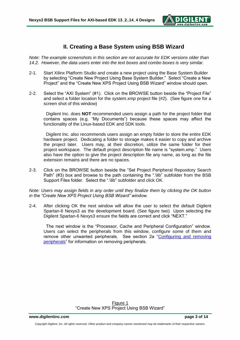
Users can remove a peripheral by clicking on the specific peripheral (#1) and then selecting “Remove” (#2). (See figure three for details)
Figure 3 Removing a Peripheral in BSB
When users select a peripheral the system shows those parameters, if any, that they can configure in BSB. For example, figure four shows the selection of the interrupt option for the Digilent USB-EPP interface. Selecting the “Use Interrupt” option for any peripheral with the option will make BSB add an interrupt controller to the system. If no other peripheral has this option, users must follow the steps in 2a to use interrupts with the Digilent USB-EPP interface. Because the Digilent USB-EPP interface is a custom core, users will have to manually connect the interrupt signal to the interrupt controller. Refer to section 3a “Connecting internal and interrupt signals” for additional information. Users must click FINISH after they have selected and configured their desired cores. Clicking FINISH generates the Base System and the Xilinx Platform Studio (XPS) brings up the “System Assembly View” to show the Bus Connections for the available peripherals.
Figure 4 Selecting the interrupt option for the Digilent USB-EPP interface
1
2
Nexys3 BSB Support Files for AXI-based EDK 13_2..14_4 Designs
www.digilentinc.com page 6 of 14
Copyright Digilent, Inc. All rights reserved. Other product and company names mentioned may be trademarks of their respective owners.
III. Making Connections for the Custom Cores
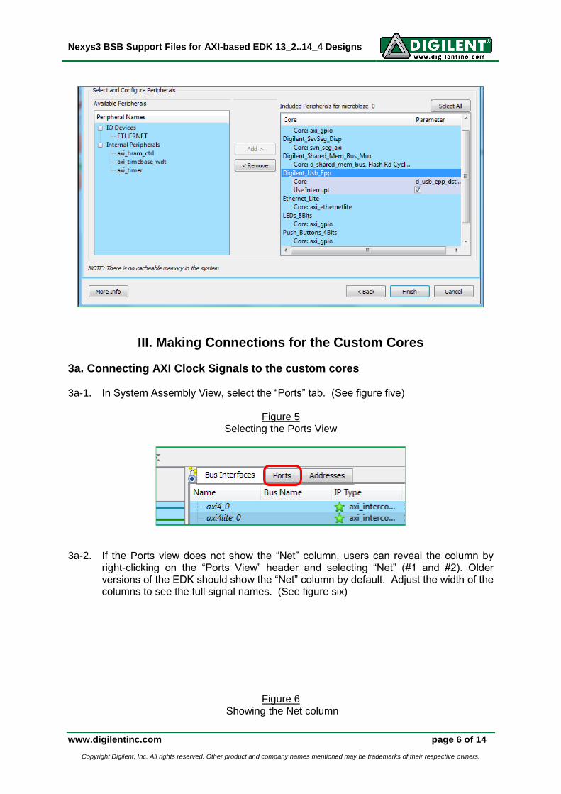
3a. Connecting AXI Clock Signals to the custom cores 3a-1. In System Assembly View, select the “Ports” tab. (See figure five)
Figure 5
Selecting the Ports View
3a-2. If the Ports view does not show the “Net” column, users can reveal the column by
right-clicking on the “Ports View” header and selecting “Net” (#1 and #2). Older versions of the EDK should show the “Net” column by default. Adjust the width of the columns to see the full signal names. (See figure six)
Figure 6 Showing the Net column
1 2

Nexys3 BSB Support Files for AXI-based EDK 13_2..14_4 Designs
www.digilentinc.com page 7 of 14
Copyright Digilent, Inc. All rights reserved. Other product and company names mentioned may be trademarks of their respective owners.
3a-3. Expand “Digilent_Usb_Epp” and then the “(BUS_IF) S_AXI.” Select the connection
signal “clk_100_0000MHzPLL0” for the “S_AXI_ACLK” in the “Net” column. (See figure seven)
Figure 7
Connecting the AXI clock signal for a custom core
Note: The signal “clk_100_0000MHz” is both the processor clock and the AXI clock as long as the “Processor, Cache and Peripheral Configuration” window (its lower part is shown in figure three) clock frequency did not change from 100 MHz. Run “clk_frequencyMHz” to name the system clock signal and remember to add the PLL number for larger devices, “clk_frequencyMHzPLLnumber.” 3a-4. Repeat Step 3a-3 above for the “Digilent_SevSeg_Disp” and
“Digilent_Shared_Mem_Bus_Mux,” if either of these cores is present in the system.
3b. Making external port connections for the custom cores
1. Right-Click
2
Nexys3 BSB Support Files for AXI-based EDK 13_2..14_4 Designs
www.digilentinc.com page 8 of 14
Copyright Digilent, Inc. All rights reserved. Other product and company names mentioned may be trademarks of their respective owners.
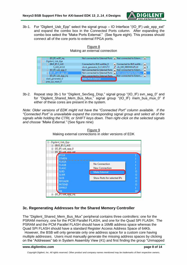
3b-1. For “Digilent_Usb_Epp” select the signal group – IO Interface “(IO_IF) usb_epp_ext” and expand the combo box in the Connected Ports column. After expanding the combo box select the “Make Ports External.” (See figure eight). This process should connect all of the core ports to external FPGA ports.
Figure 8
Making an external connection
3b-2. Repeat step 3b-1 for “Digilent_SevSeg_Disp,” signal group “(IO_IF) svn_seg_0” and
for “Digilent_Shared_Mem_Bus_Mux,” signal group “(IO_IF) mem_bus_mux_0” if either of these cores are present in the system.
Note: Older versions of EDK might not have the “Connected Port” column available. If the “Connected Port” is unavailable expand the corresponding signal group and select all of the signals while holding the CTRL or SHIFT keys down. Then right-click on the selected signals and choose “Make External.” (See figure nine)
Figure 9
Making external connections in older versions of EDK
3c. Regenerating Addresses for the Shared Memory Controller The “Digilent_Shared_Mem_Bus_Mux” peripheral contains three controllers: one for the PSRAM memory, one for the PCM Parallel FLASH, and one for the Quad SPI FLASH. The PSRAM and the PCM Parallel FLASH should have a 16MB address space whereas the Quad SPI FLASH should have a standard Register Access Address Space of 64Kb. However, the BSB will only generate only one address space for a custom core having multiple addresses. Users must manually generate the missing address spaces by clicking on the “Addresses” tab in System Assembly View (#1) and first finding the group “Unmapped
Nexys3 BSB Support Files for AXI-based EDK 13_2..14_4 Designs
www.digilentinc.com page 9 of 14
Copyright Digilent, Inc. All rights reserved. Other product and company names mentioned may be trademarks of their respective owners.
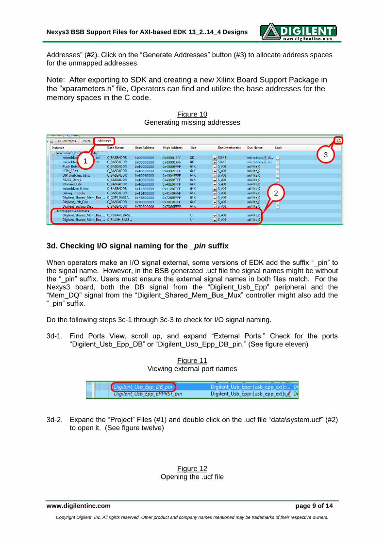
Addresses” (#2). Click on the “Generate Addresses” button (#3) to allocate address spaces for the unmapped addresses.
Note: After exporting to SDK and creating a new Xilinx Board Support Package in the “xparameters.h” file, Operators can find and utilize the base addresses for the memory spaces in the C code.
Figure 10 Generating missing addresses
3d. Checking I/O signal naming for the _pin suffix
When operators make an I/O signal external, some versions of EDK add the suffix “_pin” to the signal name. However, in the BSB generated .ucf file the signal names might be without the “_pin” suffix. Users must ensure the external signal names in both files match. For the Nexys3 board, both the DB signal from the “Digilent_Usb_Epp” peripheral and the “Mem_DQ” signal from the “Digilent_Shared_Mem_Bus_Mux” controller might also add the “_pin” suffix.
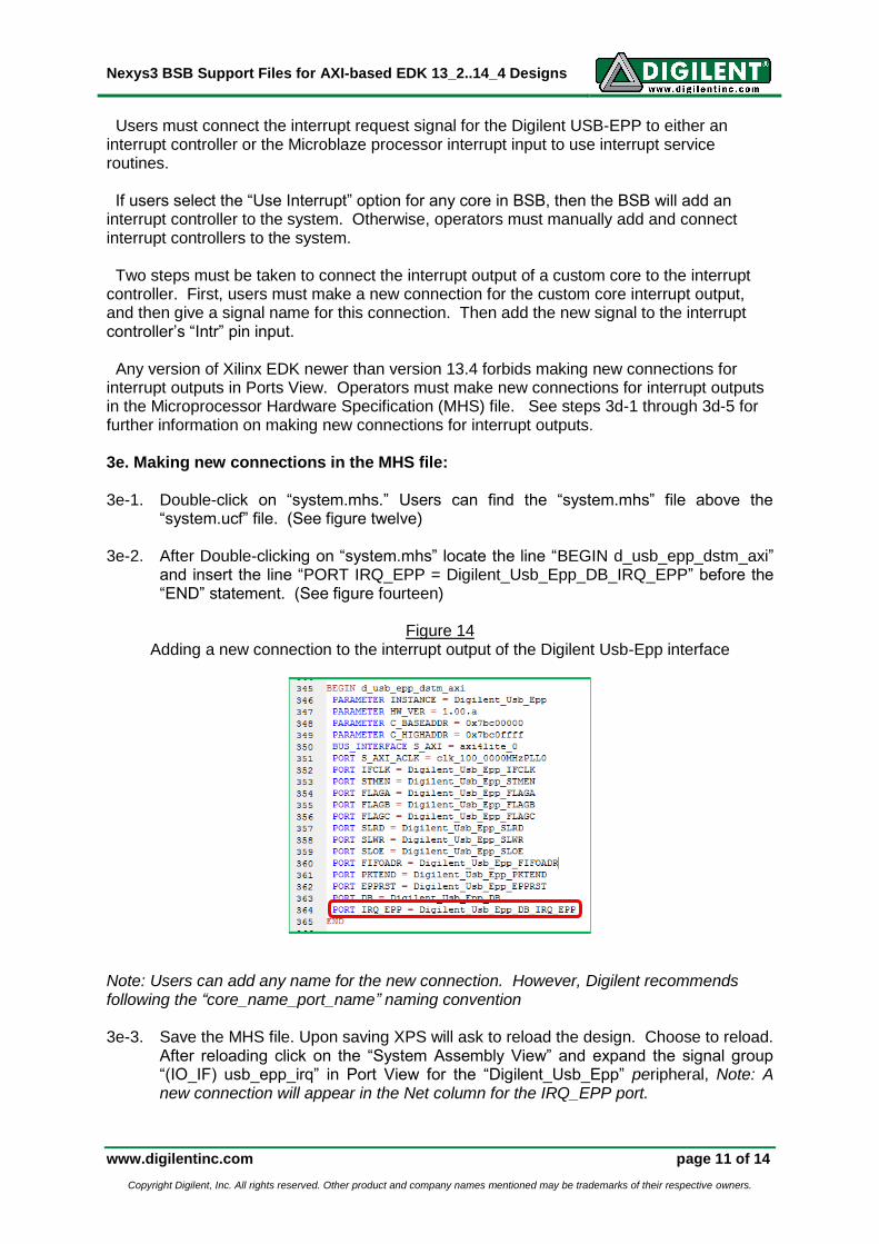
Do the following steps 3c-1 through 3c-3 to check for I/O signal naming. 3d-1. Find Ports View, scroll up, and expand “External Ports.” Check for the ports
“Digilent_Usb_Epp_DB” or “Digilent_Usb_Epp_DB_pin.” (See figure eleven)
Figure 11 Viewing external port names
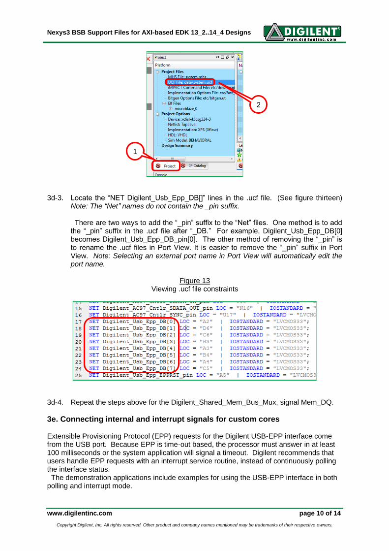
3d-2. Expand the “Project” Files (#1) and double click on the .ucf file “data\system.ucf” (#2) to open it. (See figure twelve)
Figure 12 Opening the .ucf file
1
2
3
Nexys3 BSB Support Files for AXI-based EDK 13_2..14_4 Designs
www.digilentinc.com page 10 of 14
Copyright Digilent, Inc. All rights reserved. Other product and company names mentioned may be trademarks of their respective owners.
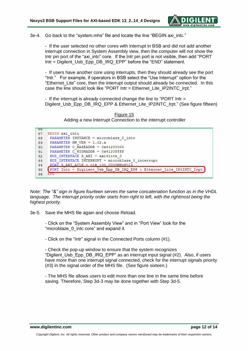
3d-3. Locate the “NET Digilent_Usb_Epp_DB[]” lines in the .ucf file. (See figure thirteen)
Note: The “Net” names do not contain the _pin suffix. There are two ways to add the “_pin” suffix to the “Net” files. One method is to add the “_pin” suffix in the .ucf file after “_DB.” For example, Digilent_Usb_Epp_DB[0] becomes Digilent_Usb_Epp_DB_pin[0]. The other method of removing the “_pin” is to rename the .ucf files in Port View. It is easier to remove the “_pin” suffix in Port View. Note: Selecting an external port name in Port View will automatically edit the port name.
Figure 13
Viewing .ucf file constraints
3d-4. Repeat the steps above for the Digilent_Shared_Mem_Bus_Mux, signal Mem_DQ.
3e. Connecting internal and interrupt signals for custom cores Extensible Provisioning Protocol (EPP) requests for the Digilent USB-EPP interface come from the USB port. Because EPP is time-out based, the processor must answer in at least 100 milliseconds or the system application will signal a timeout. Digilent recommends that users handle EPP requests with an interrupt service routine, instead of continuously polling the interface status. The demonstration applications include examples for using the USB-EPP interface in both polling and interrupt mode.
1
2
Nexys3 BSB Support Files for AXI-based EDK 13_2..14_4 Designs
www.digilentinc.com page 11 of 14
Copyright Digilent, Inc. All rights reserved. Other product and company names mentioned may be trademarks of their respective owners.
Users must connect the interrupt request signal for the Digilent USB-EPP to either an interrupt controller or the Microblaze processor interrupt input to use interrupt service routines. If users select the “Use Interrupt” option for any core in BSB, then the BSB will add an interrupt controller to the system. Otherwise, operators must manually add and connect interrupt controllers to the system.
Two steps must be taken to connect the interrupt output of a custom core to the interrupt controller. First, users must make a new connection for the custom core interrupt output, and then give a signal name for this connection. Then add the new signal to the interrupt controller’s “Intr” pin input. Any version of Xilinx EDK newer than version 13.4 forbids making new connections for interrupt outputs in Ports View. Operators must make new connections for interrupt outputs in the Microprocessor Hardware Specification (MHS) file. See steps 3d-1 through 3d-5 for further information on making new connections for interrupt outputs.
3e. Making new connections in the MHS file:
3e-1. Double-click on “system.mhs.” Users can find the “system.mhs” file above the
“system.ucf” file. (See figure twelve) 3e-2. After Double-clicking on “system.mhs” locate the line “BEGIN d_usb_epp_dstm_axi”
and insert the line “PORT IRQ_EPP = Digilent_Usb_Epp_DB_IRQ_EPP” before the “END” statement. (See figure fourteen)
Figure 14 Adding a new connection to the interrupt output of the Digilent Usb-Epp interface
Note: Users can add any name for the new connection. However, Digilent recommends following the “core_name_port_name” naming convention 3e-3. Save the MHS file. Upon saving XPS will ask to reload the design. Choose to reload.
After reloading click on the “System Assembly View” and expand the signal group “(IO_IF) usb_epp_irq” in Port View for the “Digilent_Usb_Epp” peripheral, Note: A new connection will appear in the Net column for the IRQ_EPP port.
Nexys3 BSB Support Files for AXI-based EDK 13_2..14_4 Designs
www.digilentinc.com page 12 of 14
Copyright Digilent, Inc. All rights reserved. Other product and company names mentioned may be trademarks of their respective owners.
3e-4. Go back to the “system.mhs” file and locate the line “BEGIN axi_intc.”
- If the user selected no other cores with interrupt in BSB and did not add another interrupt connection in System Assembly view, then the computer will not show the Intr pin port of the “axi_intc” core. If the Intr pin port is not visible, then add “PORT Intr = Digilent_Usb_Epp_DB_IRQ_EPP” before the “END” statement. - If users have another core using interrupts, then they should already see the port “Intr.” For example, if operators in BSB select the “Use Interrupt” option for the “Ethernet_Lite” core, then the interrupt output should already be connected. In this case the line should look like “PORT Intr = Ethernet_Lite_IP2INTC_Irpt.” - If the interrupt is already connected change the line to “PORT Intr = Digilent_Usb_Epp_DB_IRQ_EPP & Ethernet_Lite_IP2INTC_Irpt.” (See figure fifteen)
Figure 15
Adding a new Interrupt Connection to the interrupt controller
Note: The “&” sign in figure fourteen serves the same concatenation function as in the VHDL language. The interrupt priority order starts from right to left, with the rightmost being the highest priority. 3e-5. Save the MHS file again and choose Reload.
- Click on the “System Assembly View” and in “Port View” look for the “microblaze_0_intc core” and expand it. - Click on the “Intr” signal in the Connected Ports column (#1). - Check the pop-up window to ensure that the system recognizes “Digilent_Usb_Epp_DB_IRQ_EPP” as an interrupt input signal (#2). Also, if users have more than one interrupt signal connected, check for the interrupt signals priority (#3) in the signal order of the MHS file. (See figure sixteen.) - The MHS file allows users to edit more than one line in the same time before saving. Therefore, Step 3d-3 may be done together with Step 3d-5.

Nexys3 BSB Support Files for AXI-based EDK 13_2..14_4 Designs
www.digilentinc.com page 13 of 14
Copyright Digilent, Inc. All rights reserved. Other product and company names mentioned may be trademarks of their respective owners.
Figure 16 Checking for interrupt inputs and its priorities for an interrupt controller
Users can make all of the connections presented in section three by editing the MHS file. However, operators may find that Port View is easier and more error-proof than making connections in the System Assembly View. Be careful when editing the MHS file. Improper connections may lead to bitstream generation failures. Also, syntax errors might cause EDK project corruption. (I.e. the situation that XPS closes the project and announces MHS errors, being unable to open it until the errors are corrected) Digilent recommends users make a backup copy of their MHS file before editing it. Users may backup their MHS File by either issuing a File -> Save As… command or by making a backup copy of the “system.mhs file” in a file explorer. Operators can find the “system.mhs file” in the root of the project directory. Users can find more information about the MHS file syntax in the “Xilinx Platform Specification Manual” UG642 chapter on “Microprocessor Hardware Specification” (MHS), available at www.xilinx.com. Note: For older versions of EDK such as 13.2 and earlier, interrupt outputs for custom cores allow new connections. After users make a new connection, they can then connect the interrupt output of a custom core through the wizard shown in figure fifteen by selecting the specific signal and clicking the right facing arrow “->.”
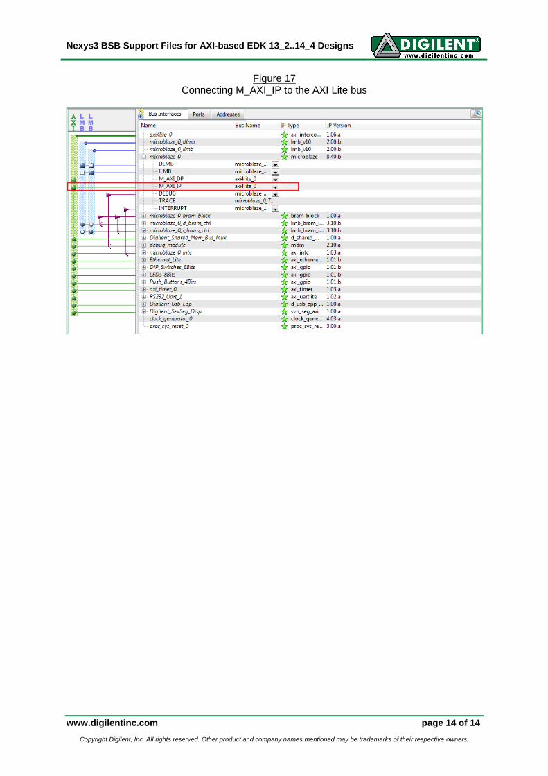
3f. Connecting Microblaze instruction port to the Shared Memory Controller In order for Microblaze to execute a program that is stored in the PSRAM, the instruction port must be connected to the AXI Lite bus. Under the “Bus Interfaces” tab, ensure that the M_AXI_IP port of the Microblaze processor is connected to “axi4lite_0” as a master. This is indicated by a solid green box, as seen below.
1
2
3
Nexys3 BSB Support Files for AXI-based EDK 13_2..14_4 Designs
www.digilentinc.com page 14 of 14
Copyright Digilent, Inc. All rights reserved. Other product and company names mentioned may be trademarks of their respective owners.
Figure 17 Connecting M_AXI_IP to the AXI Lite bus