needed for the - ERIC
88
DOCUMENT RESUME ED 028 280 08 VT 007 998 By-Adams, Jon P. A Guide for Planning Facihties for Occupahcf ''reparation Programs in Automotive Service. Research 29. Ohio State Univ., C" !As. Center for 7,-;caticai.,-1 and Technical Education. Spans Agency-Cffice of Edwation (DHEW), Wathington, Bureau No-BR-7-0158 Pub Date Apr 69 Grant - OEG-3-7 -000158 -2037 Note- 89p. Available from-Center for Vocational and Technical Educatun, Ohio State University, 1900 Kenny Road. Columbus, Ohio 47210 ($2.00) EDRS Price MF-$0.50 HC-$4.55 Descriptors- Annotated Biblioarzphies, *Auto Mechanics, *Educational Facilities, Educational Planning, *Educational Specifications, *Facility Guidelines, Facility Requirements, Instructional Programs, Rating Scales, Records (Forms), *School Shops, Spate Utihzahon, Vocational Education The major purpose of this guide is to elicit the information needed for the writing of educational specifications used in the planning of educational facilities for automotive servicing programs. It is for krze by instructors, supervisors, school plant planners, and local school officials. Part I is a docussion of the major purpose , the underlying assumptions, the guiding principles, and the recent trends which were utilized in the preparation of the guide. 'z\irt II provides data collection instruments covering basic program features, objectives, and the kinds of programs organized to implement the objectives. Part III contains data collection instruments covering facts relative to the actual desired space. Part IV is an annotated bibliography of 24 related items published between 1959 and 1968. Fifteen data collection instruments are included. A related document is "A Guide to Systematic Planning for Vocational and Technical Schools" (VT 007 825). (EM)
Transcript of needed for the - ERIC

DOCUMENT RESUME
ED 028 280 08 VT 007 998
By-Adams, Jon P.A Guide for Planning Facihties for Occupahcf ''reparation Programs in Automotive Service. Research 29.Ohio State Univ., C" !As. Center for 7,-;caticai.,-1 and Technical Education.Spans Agency-Cffice of Edwation (DHEW), Wathington,Bureau No-BR-7-0158Pub Date Apr 69Grant - OEG-3-7 -000158 -2037Note- 89p.Available from-Center for Vocational and Technical Educatun, Ohio State University, 1900 Kenny Road.Columbus, Ohio 47210 ($2.00)
EDRS Price MF-$0.50 HC-$4.55Descriptors- Annotated Biblioarzphies, *Auto Mechanics, *Educational Facilities, Educational Planning,*Educational Specifications, *Facility Guidelines, Facility Requirements, Instructional Programs, Rating Scales,Records (Forms), *School Shops, Spate Utihzahon, Vocational Education
The major purpose of this guide is to elicit the information needed for thewriting of educational specifications used in the planning of educational facilities forautomotive servicing programs. It is for krze by instructors, supervisors, school plantplanners, and local school officials. Part I is a docussion of the major purpose , theunderlying assumptions, the guiding principles, and the recent trends which wereutilized in the preparation of the guide. 'z\irt II provides data collection instrumentscovering basic program features, objectives, and the kinds of programs organized toimplement the objectives. Part III contains data collection instruments covering factsrelative to the actual desired space. Part IV is an annotated bibliography of 24related items published between 1959 and 1968. Fifteen data collection instrumentsare included. A related document is "A Guide to Systematic Planning for Vocationaland Technical Schools" (VT 007 825). (EM)

0Z
Zux!6;
to)Ct
timbhielb.<
OBZ
aim
mon
isC ma ictClat
Lill atCU CZ
CC ra3 GI CCszc OMUm UM CS

The Center for Vocational and Technical Education has
been established as an independent unit on The Ohio State
University campus with a grant from the Division of
Comprehensive and Vocational Education Research, U. S.
Office of Education. It servet a catalytic role in
establishing consortia to focus on relevant problems in
vocational and technical education. The Center is
comprehensive in its commitment and responsibility,multidisciplinary in its approach, and interinstituti.onal
in its program.
The major objectives of The Center follow:
1. To provide continuing reappraisal of the
role and function of vocational and tech-
nical education in our democratic society;
2. To stimulate and strengthen state, regional,
and national programs of applied research
and development directed toward the solution
of pressing problems in vocational and
technical education;
3. To encourage the development of research to
improve vocational and technical education
in institutions of higher education and
other appropriate settings;
4. To conduct research studies directed towardthe development of new knowledge and newapplications of existing knowledge in
vocational and technical education;
S. To upgrade vocational education leadership
(state supervisors, teacher educators,
research specialists, and others) through
an advanced study and inservice education
program;
6. To provide a national information retrieval,
storage, and dissemination system for
vocational and technical education linked
with the Educational Resources InformationCenter located in the U. S. Office of
Education.

U.S. DEPARTMENT Of HEALTH, EDUCATION & WELFARE
OffICE Of EDUCATION
THIS DOCUMENT HAS BEEN REPROMD EXACTLY AS RECEIVID FROM THE
trtR5OP OR ORGANIZATION ORIGINATING IT. POINTS Of VIEW OR OPINIONS
STAUD DO NOT NECESSARILY REPRESENT OfFICIAL NOCE Of EDUCATION
POSITION OR POLICY.
INTERIM REPORTGRANT NO. 0EG-3-7-000158-2037
RESEARCH 29
IN 411ONIOT1VE SERVICE
JON P. ADAMS
THE CENTER FOR VOCATIONAI AND TECHNICAL EDUCATIONTHE OHIO STATE UNIVERSITY 1900 KENNY ROAD
COLUMBUSt OHIO 43210
APRI L 1969
This publication was prepared pursuant to a grant with the Office ofEducation, U.S. Department of Health, Education and Welfare, contractorsundertaking such projects under Government sponsorship are encouraged toexpress freely their judgment in pro,asional and tee/mica! matters. Points ofview or opinions do not, therefore, necessarily represent official Office ofEducation position or policy.

FOREWORDOne of the most fundamental concerns in planning for vocational
and technical education facilities is that of assuring that educa-tional requirements dictate the nature of the facilities. Otherconcerns include planning a sufficiently adaptable and flexiblestructure to permit needed modifications and programmatic changesover the lifetime of the building. Experiences have shown thatadequate manuals and guide materials can provide substantialassistance in planning educational facilities. This document is aguide for planning facilities for occupational preparation programsin automotive services. The information recorded in the guide isto be used in the preparation of educational specifications.
The guide lists a series of pivotal questions about the educa-tional program to be offered. The answers to these program questionsbear directly on th. numbers and kinds of instructional areas neededin the contemplated facilities. After program decisions arerecorded, the guide provides fe: the description of instructionalareas needed to meet program requirements. Much of the material ispresented in a checklist format which allows for consideration ofalternatives in facility planning.
The guide was designed for use by any person or groups ofpersons responsible for planning automotive service trainingfacilities. It is anticipated that knowledgeable persons such asautomotive service instructors, state supervisors, university schoolplant planners, and local administrators will find the guide auseful planning tool. The guide can also be used for instructionalpurposes at universities, colleges, seminars, and institutes.
This guide is the seventh in a series being developed by TheCenter. Subsequent guides will be published for dental technology,electrical technology, and medical technology. The first six guidesdeveloped were in the fields of home economics, machine trades, dataprocessing, business and office occupations, animal science techno-logy, and metallurgy technology. All guides follow the generalformat developed by The Center project staff and M. J. Conrad,head, Administration and Facilities Unit, College of Education, TheOhio State University. Vocational educators should also refer tothe basic guide, A Guide to S stematic Plannin for Vocational andTechnical Education .aci ties.
The Center for Vocational and Technical Education, The OhioState University, worked cooperatively with Jon P. Adams, dean,Technical-Vocational Instruction, Schoolcraft College, Livonia,Michigan in preparing this planning guide. Center project staffmembers were Richard F. Meckley, Ivan E. Valentine, and Zane McCoy.
The Center is grateful to the many individuals and groupswhose assistance and suggestions led to the successful conclusionof the project. Special appreciation is due Samuel D. Morgan,Richmond Technical Institute, Rockingham, North Carolina, and LowellA. Welsh, director, Nebraska Vocational Technical School, Milford,Nebraska for their thoughtful and helpful review of the initialdraft of the guide.
Robert E. Taylor, DirectorThe Center for Vocationaland Technical Education

pcNP.Alat 1140
v
PART I INTRODUCTION
3 Purpose of Guide3 Organization of Guide4 Underlying Assumptions4 Recent Instructional Trends
5 Guiding Principles
PART II THE INSTRUCTIONAL PROGRAM
7 Basic Program Features9 Educational Objectives
11 Program Content Areas14 Planning Instructional Areas by Modes of Learning
15 Specialized and Multi-Use of Instructional Areas
16 Occupational Preparation Programs to be Offered
17 Instructions for Completing Form A
20 Form A--Basic Program Information
PART III DISTINCT TYPES OF INSTRUCTIONAL AREAS TO BE PROVIDED
25 Quantitative Facility Needs27 Instructions for Completing Form B
29 Form B--Lecture/Demonstration Area Requirements by
Content Areas31 Instructions for Completing Form C
33 Form C--Seminar Area Requirements by Content Areas
35 Instructions for Completing Form D
37 Form D--Laboratory Area Requirements by Content Areas
39 Form E--Summary of Facility Requirements for Automotive
Service Occupational Preparation Programs
41 Qualitative Facility Needs *
42 Form F--Description of Lecture/Demonstration Area(s)
46 Form G--Description of Seminar Area(s)
49 Form H--Description of Engine, Electrical and Fuel
Laboratory Area(s)57 Form I--Description of Alignment and Steering
Laboratory Area(s)62 Form J--Description of Brake and Brake Power Systems
Laboratory Area(s)67 Form K--Description of Drive Line and Transmission
Laboratory Area(s)71 Form L--Description of Accessories and Power Units
Laboratory Area(s)76 Form M--Description of Other Planning Considerations
Related to the Entire Automotive Laboratory
80 Form N--Additional Planning Considerations
PART IV ANNOTATED BIBLIOGRAPHY
81 Selected References

OCCU PAHONAL 1'R()CRA IS4.1r.valmaig MENEM.
IN AUTOMOTIVE SERVICE

PART i
INTRODUCTION
PURPOSE OF GUIDE
The major purpose of this guide is to elicit the necessary
information for the writing of educational specifications for
facilities to house needed programs in automotive service.
In addition to the major purpose of providing important and
comprehensive information to be incorporated in educational
specifications, the guide is also designed to:
Assist planners in the formation of creative solutions
to the housing of desired educational programs.
Prevent important considerations from being overlooked
in the facility planning process.
Encourage logical and systematic facility planning.
ORGANIZATION OF GUIDE
The facility planning guide is organized under four major
headings or parts. Part I (Introduction) is a discussion of the
major purpose, the underlying assumptions, recent instructional
trends, and the guiding principles which were utilized in the
preparation of the guide.
In Part II (The Instructional Program) important information
is sought on automotive service basic program features, objectives,
and the kinds of programs which will be organized to implement them.
In Part III (Distinct Types of Instructional Areas to be
Provided) the actual spaces desired to house the programs are
described in detail.
Part IV is an annotated bibliography of reference sources
which offer a more detailed treatment of the various phases of
facility planning.
3

UNDERLYING ASSUMPTIONS
Important assumptions were made in the preparation of thisguide. They were:
Major educational program decisions have or are beingmade. Content of instruction has been determined througheducational surveys, advisory committees, school boardstudy, etc. Instructional methods have been determined byqualified automotive service and other appropriate staffmembers. To assure adequate educational program planning,the guide will ask important questions which may serve asguidelines to such planning.
A cooperative and collaborative relationship has beenestablished with knowledgeable local agencies who areaware of economic, political, and social conditions whichmust be taken into account in short- and long-rangeeducational planning.
Educational, economic, political, and social planning hasrevealed the approximate numbers and kinds of students(school-age and adult) to be served by the proposedschool. Such information has been provided by enrollmentprojections, census tract data, student interest studies,etc.
The information recorded in this document will be used inthe preparation of educational specifications for use byan architect(s) in facility design.
Sufficient funds are or can be made available to supportboth the provision of facilities and the operation of thedesired occupational preparation programs.
RECENT INSTRUCTIONAL TRENDS
Expanded programs to reach not only the average and thosewho are college bound, Lut also the unusually gifted, thephysically handicapped, the mentally retarded, and theculturally disadvantaged are needed and being provided byoccupational preparation programs.
Cooperation among instructors in developing interdisci-plinary units or courses is increasing. Cooperativeinstruction is encouraged and facilitated by the proximityof instructional and work areas where the teachers canplan together and produce instructional materials.
Mobile equipment and convenient space for storing it ismaking the same space available for many purposes andresulting in more effective and efficient use of. space.
Mechanical and electronic teaching aids are being utilizedto a greater degree by instructors in occupational
4

preparation programs. To some extent, the effective
use of such devices depends upon the acce:25ibility
and convenience of storage.
GUIDING PRINCIPLES
In planning fac. ities to house occupational preplration
programs, it is suggested that educational progrum and facility
decisions be consistent with the following guiding principles.
The educational program is the basis for planning space
and facilities.
Space and facilities should accomodate changes in the
educational program.
The program must serve the needs of a variety of groups
in the community.
Space and facilities for the program can be extended
through the use of community resources.
Safe and healthful housing must be provided for al]
students.
Space and facilities for occupational preparation pre-grams
should be considered in context with the total educational
program of the institution and the community,

PART II
THE INSTRUCTIONAL PROGRAM
Part II of the guide records important instructional program
decisions with respect to basic program features, objectives, and
needed information on occupational preparation programs to be
housed.
BASIC PROGRAM FEATURES
Basic features of the educational program are determined
greatly by a school or departmentls educational philosophy. A
philosophy of education provides a base from which program
objectives and teaching and learning activities designed to meet
these objectives can be derived. In the final analysis, it is
the kinds of teaching and learning activities to be carrjed on
which shou:d determine facility needs.
In this section, planners have an opportunity to express
basic program features which will serve as guidelines for the
planned occupational preparation programs in automotive service.
Indicate below the relative degree of emphasis to be placed
on each of the program features stated by circling the appropriate
number. The scale provided for this purpose ranges from 1 for
major emphasis, 2 for .ome emphasis, 3 for slight emphasis, to N
for no emphasis. Ihis same scale will be used frequently through-
out the planning guide.
Purpose of program
a. The purpose of the program will be to
orient the student or trainee to the
following levels of automotive service:
1) Automotive service specialist (for
the gas and oil industry)
1 major emphasis2 some emphasis3 slight emphasisN no emphasis
1 2 3 N
6/7

1 major emphasis2 some emphasis3 slight emphasisN no emphasis
2) Auto mechanic3) Service technician (diagnostician)4) Service managementTo give students background which providesfor:1) Shop safety2) Shop organization3) Application of technical information4) Ability to analyze each job
c. To prepare trainees for gainful employmentin one of the levels of automotive servicementioned under (a) above
d. To give the student the background andtraining needed for him to continue hiseducation beyond this program and to knowthe kinds of training available and sourcesof information needed to keep abreast ofindustry changes
e. To provide leadership training to enabletrainens to move into higher echelons ofservice (i.e. management)
f. Other program purposes which should beincluded are:
1 2 3 N1 2 3 N1 2 3 N
1 2 3 N1 2 3 N1 2 3 N1 2 3 N
1 2 3 N
1 2 3 II
2 3 N
2. Students
a.
1)2)3)4)
Student admission to the program is on thebasis of selective criteria which include:1)2)
3)
b.4)The program will place emphasis on skill
c.acquisition.The program will place emphasis on the
1 2 3 N
d.learning of theory.Students will have freedom of movement
1 2 3 N
e.
and access to learning materials.Students will be encouraged to act
1 2 3 N
f.independently.Students will be provided with coopera-
1 2 3 N
g.
tive work experience outside the school.Other basic program features relating tostudents which should be included are:
1 2 3 N
1)2)3)
4)
8

Instruction
The instructional approach will be single
discipline (automotive service) as opposed
to inter-disciplinary (automotive service,
science, etc.). If not a single discipline
approach, describe the inter-disciplinaryapproach and the disciplines involved
ooperative or team instruction wi
used. If this mode of instruction is
be extensively emphasized, describe in
general terms.
c. ommunity resources wi ut1iZc4 in
instruction. If a high emphasis is to be
placed on use of community resources,describe some of these resources.
d. TEStructiona en. 1 ty is require.
If a high epphasis is to be placed on
instructional flexibility, please describe
the kinds of flexibility desired
S.1011.11. 1.31.111N10111[
4. Other basic program features important to the
planned instructional program:
a.
b.
C.
EDUCATIONAL OBJECTIVES
Yes No
Yes No
Yes No
Yes No
Educational objectives are often identified as goals or
outcomes of the educational program. An objective should describe
a desired educational outcome that is consistent with a school's
philosophy.

Objectives are important to both the planner and the architectsince they determine the school's program and related activities.They provide important implications which when translated intofacilities can both enhance as well as adequately house thedesired program. Thus it becomes imperative to clearly establishthe program objectives prior to embarking on educationalspecifications and subsequent building design.
The purpose of this part of the guide is to bring togetherthese elements in a way to provide direction and understandingfor both the planner and the architect. Space is provided belowto indicate degree of emphasis by circling the appropriate numberfor each of the objectives, and to list additional objectives.The scale provided for this stated purpose ranges from 1 formajor emphasis down to N for no emphasis.
To prepare students for entry intogainful employment.
To motivate and recruit capable andqualified students to enroll in post-secondary school programs.
To permit students to retrain or returnto continue training.
To provide pre-professional educationaltraining for students who plan to entercolleges and universities.
S. To develop the ability and desire to workand live harmoniously together with mutualrespect for the rights of others.
6. To develop in each student an understandingof the mechanical and scientific principalsinvolved in the automobile.
7. To develop the ability to use and care forthe basic automotive tools and specializedequipment used in the following areas:
a. Enginesb. Fuel systemsc. Electrical systemsd. Suspension systemse. Brake systemsf. Drive line and standard transmissionsg. Transmission--automatich. Accessory systems--such as power seats,
brakes, etc.
10
1 major emphasis2 some emphasis3 slight emphasisN no emphasis
1 2 3 N
1 2 3 N
1 2 3 N
12 3 N
2 3 N
1 2 3 N
1 2 3 N1 2 3 N1 2 3 N1 2 3 N1 2 3 N1 2 3 N1 2 3 N
1 2 3 N

To develop sufficient skills and relatedtechnical knowledge of the trade to meetminimum entry requirements of the automotive
industry.
To develop an understanding of logical stepby step diagnostic procedure.
a. Engine and componentsb. Steering and alignmentc. Brakesd. Accessories
10. To develop good work habits of orderliness,cleanliness, and care of property.
a. Engine rebuildingb. Drive linec. Steeringd. Brakes0. Tool cribf. Parts departmentg.
11. To develop safe work habits and to promotesafety consciousness.
12. To motivate the student to aspire to higherlevels--or to the highest of his ability.
13. Other program objectives include:
a.b.C.d.
IIMM11.411111.014111.1MINFIM.M.
PROGRAM CONTENT AREAS
1 major emphasis2 some emphasis3 slight emphasisN no emphasis
2 3 N
1 2 3 N1 2 3 N1 2 3 N1 2 3 N
1 2 3 N1 2 3 N1 2 3 N1 2 3 N1 2 3 N1 2 3 N1 2 3 N
1 2 3 N
1 2 3 N
Occupational preparation programs in automotive service or
automotive technology should be designed to meet established
objectives. All decisions made with respect to educational
programs should be consistant with established philosophy and
objectives.
Instruction in the automotive field can be provided on a
number of levels. This could include the service specialist (see
D.O.T. 7-81) a person trained in the areas of service usually
performed in the gas and oil industry. The areas of service which
may be performed in the well equipped service station include:
11

1. Wheel bearing and seal service2. Cooling system service3. Spark plug service4. Exhaust system serviceS. Battery service6. Lighting circuit service7. Automatic transmission--minor service8. Tire service9. Minor brake service
10. Lubrication and preventive maintenance procedures
In the post high school automotive service or the automotivetechnician program, major emphasis should be on the elements relatedto the performance of the automobile. These can be grouped intothe following areas:
1. Engine and related performance areas--electrical andfuel
2. Alignment--steering and all related accessories whichhelp keep the car on the road
3. Brakes and all related accessories which assist instopping the automobile
4. Drive line and transmissionsS. Accessoriespower units of all types, instruments,
safety accessories
The content areas listed above are used in this planning guidebecause the facilities for each of these represent specializedareas and special equipment. In addition the supporting servicesin the academic areas are elements such as:
6. English, mathematics, government and speech
The following areas are directly related to the automotivefield:
7. Air conditioning, physics, automotive accounting,management
Instruction in the vast field of automotive service may includecareer opportunities in the following areas: automotive mechanic,specialty mechanic, shop foreman, service writer, service salesman,service manager, parts manager, service station operator. It alsoincludes career opportunities related to sales such as: jobbersalesman, insurance and claims adjuster, automobile dealer.
This guide is designed to assist in the planning of facilitiesrelated only to preparation of programs leading to a career inautomotive service.
In occupational preparation, the courses or units of instructionemphasize -he students acquisition of knowledge, the development ofunderstandiLg attitudes and skills relevent to occupational prepara-tion, the utilization of specialized skills, and the application ofapplied scientific principles in the field of automotive service.Learning activities and experiences are organized to enable studentsto develop competencies essential for success in the automotive
12

service industry. In addition the opportunity should be provided
for upgrading the skills of people who are presently engaged in
this occupation.
Instruction in automotive service is usually presented in
well defined subject areas. The subject areas of necessity at
times may be grouped in clusters because of the relationship of
components. An example is the relationship of steering components
to the total front end and geometry.
In keeping with the modern trends of the automotive industry--
which places the major emphasis on the factors concerning perfor-
mance and de-emphasizes the heavy repair aspect such as engine
rebuilding--the programs related to performance may be placed in
five content areas related to performance and operation. These
are: 1) engine and related performance areas--electrical and fuel;
2) alignment--steering and all related accessories which help keep
the vehicle on the road; 3) brakes aad all related accessories which
help stop the vehicle; 4) drive line and transmissionsequipment
used to transmit power from the engine to the drive wheels; 5)
accessories--power units of all types (windows, seats, etc.,)
instruments and safety accessories, as well as convenience items
such as air conditioning.
The five content areas listed above related directly to the
performance of the vehicle and will include most up to date
occupational preparation related to SERVICE--service being defined
previously as the functions of the vehicle related to 1) power;
2) control (keeping the vehicle on the road); 3) stopping; 4)
transmission of power to wheels; 5) accessories (safety, convenience
and power assisted).
The automotive service program should include: 1) the basic
understanding of the automobile and all of its components; 2) the
instruction directly related to the automotive area, i.e., air
conditioning; 3) instruction in academic areas directly related to
automotive service, i.e., applied physics; 4) academic instruction
essential to the individual as well as the program, i.e., communi-
cation skills; and at least some exposure to general education,
ie., political science, basic accounting.
An example of a program designed to provide occupational
competency in automotive service may include the following:
Courses
Communication SkillsBasic ElectricityPhysical EducationFront End Alignment
Content Area
AcademicSciencePhysical EducationAlignment and Steering
The concept of content areas is used in this planning guide
beause different instructionarEmcent areas usually call for
different kinds of instructional facilities and equipment. The
following content areas, which usually call for specialized
instructional areas, are used in this guide.
13

Engines--electrical and fuelAlignment and steeringBrakes and power systemsDrive line and transmissionsAccessories and power unitsAcademic supporting services (e.g., English mathematics)
Science--physicsPhysical educationOthers
PLANNING INSTRUCTIONAL AREAS BY MODES OF LEARNING
The planning of instructional areas for occupational prepara-tion facilities can be substantially aided through utilization of
the concept of modes of learning. Learning can be divided into
three distinct modes--reaction learning, interaction learning, and
action learning.
Reaction learnin witch usually occurs in an instructional
area iIgnedfor Iiiture and demonstration, is characterized by
activities which tinT37576-773TETTUWEEBT-centered with thecentral focus on instruction. Student activities include listening,observing, and the taking of notes. Group size may vary from one
to a very large number as the number of students has little effect
on the learning experience if proper technological aids such as
television, microphones, projectors and the like are used. Because
student activities are relatively passive in reaction learning ashort optimal type span is normally employed.
Lecture/demonstration areas can be used commonly for reactionlearning in all subject areas. For example, in planning facilitiesfor two diverse occupational preparation programs in automotiveservice such as front end alignment and brake service, the planner
should bear in mind that reaction learning for students in bothprograms can occur in the same kind of instructional area. This
means that facility planning should be done in terms of the total
program rather than its fractional part. In many instances, lecture/demonstration areas can be shared not only by occupational prepara-
tion programs within vocational service areas, but also shared by
distinct and dissimilar service areas, such as automotive service
and highway technology. Where a great deal of facility sharing is
planned, the planner should consider the optimal location within the
total building and the advisability of clustering variousinstructional areas.
Interaction learning, which usually occurs in a seminarinstructional area, is c aracterized by both teacher and learneractivity participating as both listener and speaker. This mode
of learning, of course, must occur in groups; however, sociologicalresearch suggests these groups should not exceed 15 persons for
optimal effectiveness. Active interaction of all students generally
requires a longer time span than reaction learning.
Seminar areas, like lecture/demonstration areas, are usuallydesigned for common use by all vocational service areas. The same
considerations which were outlined for lecture/demonstration areasalso apply to seminar areas.
14

Action learning, which usually occurs in a laboratorinstriTEMEWFWarallows individual students to earn y doing.
Students learn on an individual basis, but may, nevertheless,
function in a group setting. Often in more flexible types of
educational programs, students are scheduled for laboratory work
on an individual basis. Since action learning involves overt
action by individual students, the teacher's role is largely that
of a consultant to the learner.
Laboratory areas, of necessity, are more specialized than
lecture/demonstration areas used for reaction learning and seminar
areas used for interaction learning. Since laboratory areas are
designed to facilitate the learning of specific vocational and
technical skills, there is less likelihood of sharing such areas
by students in various vocational training programs. However,
whenever common elements of skill instruction are found among
vocational training programs, the sharing and clustering laboratory
facilities can be both expedient and economical.
SPECIALIZED AND MULTI-USE OF INSTRUCTIONAL AREAS
The relative amounts of time to be spent by students in a
given vocational program in reaction, interaction, and action
learning has definite implications for the number and kind of
spaces to be provided. These time considerations combined with
decisions on the degree of s ecialization versus multi-use help
determine the nature of faci ities required. Since most voca-
tional programs have concentrated on action learning experiences,
facilities designed for a particular vocational program have
seldom provided adequate reaction and interaction facilities
because of the limited utilization of such spaces. However, if
the learning activities in any vocational program are broken down
into the modes of learning, it will be noted that reaction and
interaction spaces are the same regardless of the vocational area.
Therefore, by providing common reaction and interaction spaces
for all vocational programs, the most modern technological aids
can be justified which, in most cases, will permit lectures,demonstrations and other group reaction learning experiences for
groups larger than typically used in vocational education programs.
Not only will group reaction learning be improved but more time
will become available for the professional staff to work with
individuals and small groups in interaction and action learning
activities.
Scheduling group reaction and interaction learning experiences
into specialized facilities permits complete flexibility in the use
of action learning laboratories on an open individualized basIs
since students would no longer need to be scheduled into the action
learning laboratories on a specific class basis. This will permit
100 percent room utilization of the action learning laboratories
and also permit the introduction of differentiated staff assign-
ments into vocational education.
The open laboratory concept also permits the planned sharing
of certain specialized equipment which may be required by two or
more vocational programs.
15

r-NOTE: THE FOLLOWING SECTIONS OF THE GUIDE (PAGES 17
vi
37)l ASSIST THE PLANNER IN MAKING MATHEMATICAL DETERMINATIONS-
OF THE NUMBER OF INSTRUCTIONAL AREAS NEEDED TO HOUSE THE DESIREDPROGRAM. IF THE NUMBERS OF INSTRUCTIONAL AREAS REQUIRED AREALREADY KNOWN, THE PLANNER MAY NOW PROCEED TO FORM E, PAGE 39.
IF, HOWEVER, MATHEMATICAL DETERMINATIONS ARE TO BE MADE, ALLFORMS SHOULD BE COMPLETED AS ACCURATELY AS POSSIBLE.
OCCUPATIONAL PREPARATION PROGRAMS TO BE OFFERED
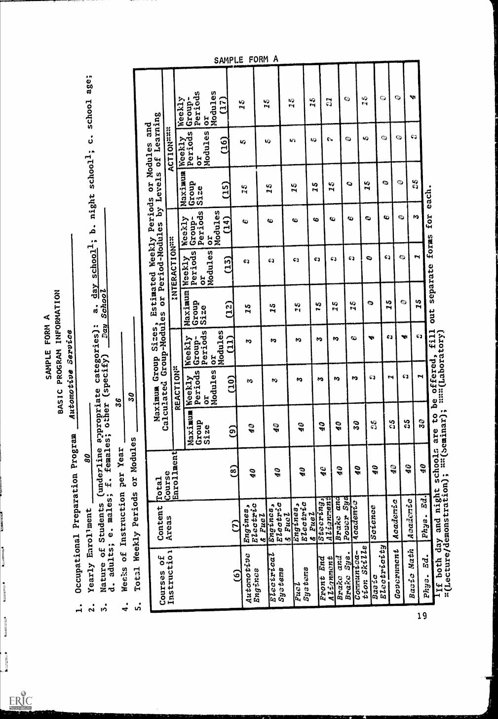
Information on each occupational preparation program to beoffered is entered on a separate Form A which follows. Directionsfor completing Form A appear on pages 17-18. To assist planners,
a sample completed Form A is given on page 19. Data entered in thesample FOTM A are for an automotive service program. The data were
assumed for purpose of illustration.
Form A for each occupational preparation program should befilled out as completely as possible. However, it is realized,for example, that an automotive instructor completing FOTM A may
be unaware of time allotments and methods of instruction in other
subject areas. If such is the case, the instructor can only supplyinformation on courses within the content areas of automotive
service.

INSTRUCTIONS FOR COMPLETING
FORM A
BASIC PROGRAM INFORMATION
Item 1 Occupational PreparationProgramEnter here the name
of the occupational program
to be
offered.
Item 2 Yearly EnrollmentEnter
here the projectedmaximum number of students
to be enrolled
yearly in the program.
Item 3 Natnre of StudentsUnderline
all categories which apply
to the students to
be enrolled
in the program.
Item 4 Weeks of Instruction per
Year--Enter here the numberof weeks per year the
school will
be open for instruction, e.g.,
36 weeks, 52 weeks.
Item 5 Total Weekly Periods orModulesEnter here the total
number of periods or modules
(if
modular scheduling is to
be used) per weekavailable for instructional purposes
for each
student.
Do not count periods ormodules scheduled for lunch or
other non-instructional
purposes.
Column 6
Courses of InstructionList
the courses or units of
instruction to be offered
either on
a required or
elective basis for the
occupational preparation program.
Column 7
Content Area--Opposite
each course of instruction,
enter the appropriate
content area as
presented on page 11.
Column 8
Total Course
Enrollment,--Opposite each course of
instruction, enter the projectedmaximum
student enrollment.
Column 9
Maximum Group Size forReaction LearningOpposite
each course or unit of
instruction,
enter the maximum group
size in number of students
for reaction
(lectureidemonstration)
4type learning.

Column 10
Estimated Weekly Periods or Modules of ReactionLevel LearningOpposite each course or
unit of instruction, enter the
estimated number of periods or modules per week to
be
co
devoted to reaction learning per student.
Column 11
Weekly Group-Periods or Modules
(Lecture/Demonstration)--To compute weekly group-periods
or modules, divide
the entry in Column 8 by the entry in Column 9 and
round up to the
nearest whole number.
Then multiply the whole number by the entry in Column
10.
Column 12
Maximum Group Size for Interaction LearningOpposite
each course or unit of instruction,
enter the maximum group size innumber of students for interaction (seminar) type
learning.
Column 13
Estimated Weekly Periods or Modules or Interaction LevelLearningOpposite each course
or unit of instruction, enter
the estimated number of periods or modules per week tobe
devoted to interaction learning per student.
Column 14
Weekly Group-Periods or Modules (Seminar)--To compute weeklygroup-periods or modules,
divide the entry in Column 8 by the entry in Column 12 andround up to the nearest
whole number.
Then multiply the whole number by the entry in Column 13.
Column 15
Maximum Group Size for Action Learning--Opposite each course orunit of instruction,
enter the maximum group size in number of
students
action (laboratory) type learning.
Column 16
Estimated Weekly Periods or Modules of Action Level LearningOpposite
each course or
unit of instruction, enter the estimated number ofperiods or modules per week to be
devoted to action learning per student.
Column 17
Weekly Group-Periods or Modules (Laboratory)--To compute
weekly group-periods or modules,
divide the entry in Column 8 by the entry ia Column 15 andround up to the nearest whole
number.
Then multiply the whole number by Vic entry in Column 16.
SAMPLE FORM A
BASIC PROGRAM
INFORmATION
1.
Occupational
Preparation Program
Automotive Service
2.
Yearly Enrollment
80
3.
Nature of Students
(underline a2propriate
categories):
a. day
schoo
d. adults; e.
males; f. females;
other (specify)
Day School
4.
Weelm of Instructionper Year
36
S.
Total Weekly
Periods or Modules
30
- b. nightschooll; c, school age;
of
Instructiol
I
6
Content
Areas
7
1Total
Course
Enrollment
8
MaxiCourses
mum Group
Sizes, EstimatedWeekly Periods orModules and
Calculated Group-Modules
orPeriod-Modules by Levels
of Learning
REACTIOW
INTERACTION=
ACTION=
aximum
Group
Size 9)
Weekly
Periods
or
Modules
10
Weekly
Group-
Periods
or
Modules
11
Maximum
Group
Size 12
Weekly
Periods
or
Modules
13
Weekly
Group-
Periods
or
Modules
14
Maximum
Group
Size 15
Weekly
Periods
OrModules
16
Weekly
Group-
Periods
or
Modules
1
Automotive
Engines
Engines,
Electric
& Fuel
40
40
33
25
26
15
S15
E ectrzca
Syatems
Engules,
Electric
& Fuel
40
40
33
15
.)
4.,
615
535
FUC
Systems
Engtnes,
Electric
& Fuel
40
40
N..
33
15
,)
4.
615
515
Front
nAU2nment
Steer ng
Alisnmen
40
40
33
15
.)
4,
625
515
Brake and
Brake Sys.
Brake an
Power S
40
40
33
IS
26
15
P
Communica-
tion Skil/
Academtc
40
30
3e
15
00
0
Daeic
ElectricityScien e
40
nz
c ,.,
40
00
15
Government
Academic
40
25
24,"
41,,
60
0
Basic Math
Academic
40
25
.) u
40
00
00
Phys. Ed.
4111
k1.
1.11
11
Phys. Ed.
40
30
IIM
MIN
NIW
12
15
I3
25
24
If both day andnight schools are to
be offered, fill
out separate
forms for each.
g(Lectureidemonstration);
=(heminar);
(Laboratory)

wia
ll1,
FORM A
BASIC PROGRAM INFORMATION
1.
Occupational PreparationProgram
c)
2.
Yearly Enrollment
3.
Nature of Students
(underline appropriate
categories):
a. day
schooll; b. night schooll; c. school age;
d. adults; e. males;
f. females; other
(specify)
4.
Weeks of Instruction perYear
5.
Total Weekly Periods orModules
Courses of
Instruction
6
Content
Areas
7
frotai
JCourse
nrollment
8
Maximum Group Sizes, EstimatedWeekly Periods or Nodules and
Calculated Group-Modules or
Period-Modules by Levels of Learning
REACT10W
INTERACTION
ACTION
I
Maximum'Weekly
Group
Size
9
Periods
or
Modules
10
'Weekly Maximum
Group-
Group
'Periods
Periods Size
orModules
11
12
Weekly
orModules
13
Weekly
Group-
Periods
or
Modules
14
Maximum
Group
15
Weekly
Periods
or
Modules
16
Weekly
Group-
Periods
or
Modules
17
-I
,
1L
.........
.....
IIIIIIIMIIIIIIIII
f
If both day and night schools are
to be offered, fill out separate
forms for each.
(Lecture/demonstration); =(Seminar);
(Laboratory)

FORM A
BASIC PROGRAM
INFORMATION
1.
Occupational PreparationProgram
2.
Yearly Enrollment
3.
Nature of Students
(underline appropriate
categories):
a. day school
b. night school
c. school age;
d. adults; e. males;
f. females; other
(specify)
4.
Weeks of Instruction perYear
S.
Total Weekly Periods orModules
Courses of
Instruction
IIIIIIIIIIIIIIIIIIIIIIIIII.
ill
alilailll
IIIIIIIIIIHIIIIIIIHMIIIIMIIIIIIIIIIIIIHIIIIIMIIIIIIIIIIII
11111111111111111111111111111EM
Content
Areas
otal
ourse
nrollment
Maximum Group Sizes,
Estimated Weekly Periods orNodules and
Calculated Group-Modules or
Period-Modules by Levels ofLearning
REACTION%
INTERACTION%
ACTION%%%
M4ximum Weekly Weekly
,M4ximum Weekly
Group
Periods Grout- ,Group
Periods
Size
or
PeriodsSize
Or
Modules or
Modules
Modules'
910
11
12
13
Wekly 1Maximum
Group- 1Group
Periods
or
Modules
14) a=Size
15
Weekly
Periods
or
Modules
16
Weekly
Group-
Periods
or
Modules
17
allIl
1111116111111111111
IIIIMMIIIIIIII
MAE
1
11f both day and night
schools are to be offered,
fill out separate forms
for each.
x(Lecture/demonstration);
==(Seminar); ==(Laboratory)

FORM A
BASIC PROGRAM INFORMATION
1.
Occupational PreparationProgram
2.
Yearly Enrollment
3.
Nature of Students
(underline appropriate
categories):
a. dayschooll; b. night schooll; c. school age;
d. adults; e. males;
f. females; other
(specify)
4.
Weeks of Instruction perYear
S.
Total Weekly Periods orModules
Courses of
Instruction
Content
Areas
otal
ourse
Maximum Group Sizes,
Estimated Weekly Periods orModules and
Calculated Group-Nodules or
Period-Modules by Levels ofLearning
Enrollmen
REACTION
DflERACTION
ACTIO ==
Maximum
Group
Size
Weekly
Periods
or
Modules
10
Weekly
Group-
Periods
or odules
11
Maximum
Group
Size
12
Weekly
Periods
or
Modules
13
Weekly
Group-
Periods
or
;odules
14
Maximum
Group
Size 15
Weekly
Periods
or
Modules
(16)
Weekly
Group-
Periods
or
Modules
(17)
1 IIIIIIIIIIHIIIIIIIHIIIIIIHIIIIMIIIIMIIIIIIIIMIIIIIIIIHIIIIIIIIIIIIII
If both day and night
schools are to be offered,
fill out separate forms
for each.
r:(Lecture/demonstration); 2:=(Seminar);
(Laboratory)

FORM A
BASIC PROGRAM INFORMATION
1.
Occupational Preparation Program
2.
Yearly Enrollment
3.
Nature of Students
(underline appropriate
categories):
a. day school
b. night
schooll
c. school age;
d. adults; e. males; f.
females; other (specify)
4.
Weeks of Instruction perYear
S.
Total Weekly Periods orNodules
Courses of
Instruction
Conten
Areas
otal
fCourse
Enrollmen
Maximum Group Sizes, EstimatedWeekly Periods or Modules and
Calculated Group-Nodules orPeriod-Modules by Levels of Learning
REACTION14
INTERACTIO 'x
ACTION
aximum
Gro,Ap
Size
Weekly
Periods
or
Modules
10
Weekly
Group-
Periods
or
Modules
11
Naxiu m
Group
Size
12
Weekly
Periods
or
Modules
13
Weekly
Group-
Periods
or
Nodules
14
Maximum
Group
'Periods
Size 15
Weekly
or
Nodules
16
Meekly
Group-
Periods
or
Modules
17
I 11
1111111111111111111
1111111111111111
11111111
IIIIIIII
If both day and night schools areto be offered, fill out separate
forms for each.
:4(Lecture/demonstration); =n(Seminar);
===(Laboratory)

PART III
DISTINCT TYPES OF INSTRUCTIONAL
AREAS TO BE PROVIDED
QUANTITATIVE FACILITY NEEDS
The number of instructional areas to house the programs
described75Firt II (The Instructional Program) are recorded
in this section of the guide.
As indicated in Part II, there are three principal types of
instructional areas used to accommodate educational programs.
They are:
Leetureldemonetration areae--used principally for
group reaction learning;
Seminar areae--used principally for group interaction
learning; and
Laboratory areae--used principally for group or
individual action learning.
In addition to these instructional areas, there are, of course,
other school-wide auxiliary areas such as instructional materials
centers, language laboratories, gymnasiums, and auditoriums which
are part of the overall school plan. Requirements for such
facilities are calculated as a part of total school planning and
are not made in this guide.
It is recommended that facility needs, including occupational
preparation programs in automotive service, be made on a school-
wide blsis in order to provide planners with a balanced picture
of the building to be constructed and in order to provide economy
and convenience through the sharing and clustering of various kinds
of facilities and equipment.
c0,2e25

Forms B, C, and 0 can be used to compute the number of lecture/demonstration, seminar, and laboratory areas requifUTTFespectively,for the planned programs in automotive service. The use of theseforms requires some mathematical ability. Personnel responsible forcompleting the guide may want to utilize the services of individualswith this special competence.
Results of the computations on Forms B, C, and 0 are entered onForm E which is a summary of total instructional area requirementsfor automotive service occupational preparation programs.
In*the event that instructional area requirements are alreadydetermined (e.g., it has been decided that one combinationlaboratory and lecture/demonstration area will be provided) the
information can be recorded directly on Form E without making thecomputations on Forms B, C, and D.
It is strongly recommended that appropriate personnel beutilized to ensure that the number of instructional areas issufficient to meet program requirements. After the number ofeach type of instructional area is determined and recorded onForm E., information can then be recorded in the following sectionof the guide concerning the nature of these instructional areas.
2 el

c
INSTRUCTIONS FOR COMPLETING
FORM B
LECTURE/DEMONSTRATION AREAREQUIREMENTS BY CONTENT
AREAS
Column 1
Content Area--Content areas
are listed
in Column 1
Column 2
Total EnrollmentTo
obtain total enrollment
for content areas,
find the total enrollment
for each content area as
indicated in Columns 7
and 8 of Form A(s) for
all occupational
preparation programs.
Column 3
Maximum Group Size--Opposite
each content area, enter
the maximum group size
desired for
alecture/demonstration area to serve
the content area (FormA, Column 9).
Column 4
TotaZ Weekly Periods orModulesOpposite each content area,
enter the total
periods or
modules per week the
school will be open for
day school instruction.
This entry will
be identical for all
content areas and
identical to the number
recorded for Item 5,
Form A.
Column S
Total Weekly ReactionGroup-Periods or ModulesOpposite
each content area, enter
the
total group periods ormodules per week to be
devoted to reaction
learning as indicated
in Column 11 of FormA(s) for all occupationalpreparation programs.
Column 6
Lecture/Demonstration Areas
RequiredOpposite each content area,
enter the quotient
of
Item 5 divided by
Item 4.
Round up to the nearest
hundredth.
Column 7
Adjusted Lecture/DemonstrationAreas RequiredTo
adjust for scheduling
difficulties
which result in areas
being less than 100 percent
utilized, multiply the entry
in
Column 6 by 1.3 and enter
the result, rounded up to
the nearest hundredth,
in Column
7 for each content area.
Column 8
TotalsSince
lecture/demonstration areas,
unlike laboratory areas, canbe utilized by
nearly all content areas,
the entries in Column
7 can be added for all
lecture/demon-
'44
stration areas with
identical maximum group
sizes as entered in Column
3.
For example,
8a might read 2
lecture/demonstration areas with a
student capacity of SO
each.

SAMPLE FORM B
LECTURE/DEMONSTRATION AREA REQUIREMENTS BY CONTENT AREA
Content Area
(1)
Total
Enrollment
(2)
Maximum
Group
Size (3)
I
Total Weekly
Periods or
Modules (4)
Total Weekly
Reaction Group
Periods or
Modules (5)
Lecture/Demon-
stration Areas
Required
(S)
i(4)
(6)
Adjusted Lecture/
Demonstration
Areas Required
(6) X 1.3(7)
I Engines, Electrica
and Fuel Systems
120
40
30
90.30
0.39
II Alignment and
Steering
40
40
30
30.10
0.13
III Brakes and Power
Systems
40
40
30
30.10
0.13
IV Drive Line and
Transmissions
0__
......
__
..._
V Accessories an.
Power Units
0_...
.._
......
_..
......
VI Academic
120
25
30
60.20
0.26
VII Science
40
25
30
40.13
0.1?
/III Physical Education
40
30
30
g A.0.67
0.6?
IX Ottier (specify)
(S) Totals (Figures in Column 7 can be added together for areas with same student capacity as entered in
Column 3.)
Round off total to next higher whole number.
a.
/lecture/demonstration areas with a student capacity of
40
1each.
b.
/lecture/demonstration areas with a student capacity of
25
each.
lecture/demonstration areas with a student capacity of
3C
c.
/each.
d.
lecture/demonstration areas with a student capacity of
,each.
Note:
The entries in Column 7 indicate clearly that the lecture/demonstration areas would only be used
sparingly by students enrolled in each of the content areas.
One possibility night be construc-
tion of one lecture/demonstration area with a student capacity of 40 which could be subdivided
to meet program requirements of all content areas.
Another possibility would be the sharing of
lecture/demonstration with other students enrolled in various other programs.

LECTURE/DEMONSTRATION AREA REQUIREMENTS trCONTENT AREAS
Content Area
(1)
Total
Enrolimenti
(2)
1
Maximum
Group
Size (3)
Total Weekly
Periods or
Modules (4)
Total Weekly
Reaction Group-
Periods or
Modules (5)
Lecture/Demon-
stration Areas
Required
(S)
..r
(4)
(6)
Adjusted Lecture/
Demonstration
Areas Required
(6) X 1.3(7)
1 Engines, Electrical
and Fuel Systems
II Alignment and
Steering
III Brakes and Power
Systems
IV Drive Line and
Transmissions
V Accessories and
Power Units
VI Academic
VII Science
VIII Physical Education
IX Other (specify)
(8) Totals (Figures in Column 7 can be added together for areaswith same student capacity as entered in
Column 3.)
Round off total to next higher whole number.
a.
lecture/demonstration areas with a student capacity of
each.
b.
lecture/demonstration areas with a student capacity of
,each.
c.
lecture/demonstration areas with a student capacity of
,each.
dlecturd/demonstration areas with a student capacity of
.,each.

INSTRUCTIONS FOR COMPLETING FORM C
SEMINAR AREA REQUIREMENTS BY
CONTENT AREAS
Column 1
Content AreaContent areas are
listed in Column 1.
Column 2
Totai EnrollmentTo obtain total
enrollment for content areas, find
the total enrollment
for each content area indicated
in Column 7 and 8 of FormA(s) for all occupational
preparation programs.
Column 3
Maximum Group SizeOpposite each content
area, enter the maximum group
size desired
for a seminar area to serve the content area
(Form A, Column 12).
Column 4
Total WeekZy Periods
modules per week the
be identical for all
Form A.
or ModulesOpposite
each content area, enter the total
periods Or
school will be open for day school
instruction.
This entry -will
content areas and identical to
the number recorded for Item 5,
Column S
Total Weekly Interaction GroupPeriods orModuZes--Opposite each content area, enter
the total group periods ormodules per week to be devoted to
interaction learning as
indicated in Column 14 of Form A(s)
for all occupational preparation programs.
Column 6
Seminar Areas Required--Opposite each content area,
enter the quotient of Item
divided by Item 4.
Round up to the nearest hundredth.
Column 7
Adjusted Seminar Areas Required--Toadjust for scheduling difficulties which result
in areas being less than 100 percentutilized, multiply the entry in Column 6 by
1.3
and enter the result, rounded up to
the nearest hundredth, in Column 7 for
each
content area.
Column 8
Totals--Since seminar areas, unlike
laboratory areas, can be commonly utilizedby nearly
all content areas, the entries in
Column 8 can be added for all seminar areas
with
identical maximum group sizes or
entered in Column 3.
For example, 8a might read 2
seminar areas with a student
capacity of 20, each.

1
SAMPLE FORM C
SEMINAR AREA REQUIREMENTS BY CONTENTAREAS
Content Area
(1)
Total
Enrollment
(2)
Maximum
Group
Size (3)
Total Meekly
Periods or
Modules
(4)
Total Weekll
Interaction
Group-Periods
or Modules
(5)
Seminar Areas
Required
(5) 4 (4)
(6)
Adjusted Seminar
Areas Required
(6) X 1.3
(7)
I Engines, Electrical
and Fuel Systems
220
15
30
18
0.60
0.78
II Alignment and
Steering Systems
40
15
30
60.20
0.26
_III Brakes and Power
Systems
40
15
39
60.20
0.26
IV Drive Line and
Transmissions
0--
V Accessories and
Power Systems
0__
__
...._
VI Academic
120
15
30
12
0.40
0,52
VII Science
40
15
30
0...
....
......
III Physical Education
40
15
30
30.10
0.10
IX Other (specify)
(8) Totala (Figures in Column 7 can
be
triiiamn 3.)
Round up total to next
a.
2 (1.92) seminar areas with a
b.
seminar areas with a
c.
seminar areas with a
d.
seminar areas with a
added together for aras with same
student capacity as entered in
higher whole number.
minimum student capacity of
15
,each.
minimum student capacity of
,each.
minimum student capacity of
,each.
minimum student capacity
of
each.

FORM C
SEMINAR AREA REQUIREMENTS BY CONTENT AREAS
Content Area
(1)
Total
Enrollment
(2)
Maximum
Group
Size 3)
Total Weekly
Periods or
Modules
(4)
Total Weekly
Interaction
Group-Periods
or Modules
(5)
Seminar Areas
Required
(5) 4 (4)
(6)
Adjusted Seminar
Areas Required
(6) X 1.3
(7)
I Engines, Electric
and Fuel Systems
II Alignment and
Steering Systems
II
Brakes and Power
Systems
IV Drive Line and
Transmissions
V Accessories and
Power Systems
VI Academic
VII Science
VIII Physical Education
IX Other (specify)
(8) Totals (Figures in Column 7 can be
Column 3.)
Round up total to next
a.
seminar areas with a
b.
seminar areas with a
c.
seminar areas with a
d.
seminar areas with a
added together for areas with same studentcapacity as entered in
higher whole number.
minimum student capacity of
,each.
minimum student capacity of
each.
minimum student capacity of
each.
minimum student capacity of
,each.

INSTRUCTIONS FOR COMPLETING FORM D
LABORATORY AREA REQUIREMENTS BY
CONTENT AREAS
Column 1
Content AreaContent areas are
listed in Column 1.
Column 2
Total EnrollmentTo obtain total
enrollment for content areas, find
the total enrollment
for each area as indicated
in Columns 7 and 8 of Form A for
all occupational preparation
programs.
CCIlmn 3
Maximum Group Size--Opposite
each content area, enter the maximum groupsize desired
for a laboratory area to serve
the content area (Form A, Column
15).
Column 4
Total Weekly Periods or ModulesOpposite
each content area, enter the totalperiods or
modules per week the school will
be open for day school instruction,
This entry will
be identical for all content areas
and identical to the number recorded
for Item S,
Form A.
Column S
Total Weekly Action Group-Periods or
ModulesOpposite each content area, enter
the
total group periods or modules perweek to be devoted to action learning as
indicated
in Column 17 of Form A(s) for
all occupational preparation programs.
Column 6
Laboratory Areas Requ redOpposite
each content area, enter the quotient
of Item S
divided by Item 4.
Round up to the nearest hundredth.
C4
Column 7
Adjusted Laborator Areas RequiredTo
adjust for scheduling difficulties which
result
'Ln
in areas being less than 100 percent
utilized, multiply the entry in Column 6
by 1.3 and
enter the result, rounded up to
the nearest hundredth, in Column 7 foreach content
area.

AMPLE FORM O
LABORATORY AREA REQUIREMENTS BY CONTENTAREAS
Content Areas
(1)
Total
Enrollment
(2)
Maximum
Group
Size
(3)
Total Weekly
Periods or
Modules
(4)
Total Weekly
Action Group
Periods or
Modules
(5)
Laboratory
Areas Required
(5) 4
(4)
(6)
Adjusted Areas
Required
(6) X 1.3
(7)
I Engines, Electrical
and Fuel Systems
If°
2S
30
4S
1.S0
2.9S
II Alignment and Steering
Systems
40
230
..
0.a
III Brakes and Power
Systems
40
2Z
30
f:
0.P0
0..92
IV Drive Line and
Transmissions
__
-._
__
_-
V Accessories and
Power Systems
__
__
__
__
VI Physical Education
40
30
40.23
VII Science
40
fS
30
2Z
0.0
0.a

FOR
M!)
LABORATORY AREA REQUIREMENTS BY
CONTENT AREAS
Content Areas
(1)
Total
Enrollment
(2)
Maximum
Group
Size
(3)
Total Weekly
Periods or
Modules
(4)
Total Weekly
Action Group-
Periods or
Modules
(S)
Laboratory
Areas Required
(5) 4 (4)
(6)
Adjusted Areas
Required
(6) X 1,3
(7)
I Engines, Electrical
and Fuel Systems
II Alignment and Steering
Systems
III Brakes and Power
Systems
IV Drive Line and
Transmissions
V Accessories and
Power Systems
,
VI Physical Education
VII Science

SAMPLE FORM E
SUMMARY OF FACILITY REQUIREMENTS FOR OCCUPATIONAL PREPARATION
PROGRAMS IN AUTOMOTIVE SERVICES
Instructional Areas
( )
Number Required* RequiredStudentCapacity
(4)
CalculatedForms B, C, DColumn 7 (2)
Next HigherWhole Numbe
(3
Lecture/Demonstration 0. O 2 40
Lecture/Demonstration
Lecture/Demonstration
Lecture/Demons a on
Seminar,, 2C
Seminar
Semina
SeminaEngines, Electrical, andFuel S stems Laborator
0.78 2 26
Alignment and Steering_ySstemsbalorato_______i Brakes and Powerastem LaboratoryDrive Line and TransmissionLaboratorAccessories and PowerSystems Laboratory
4 Multi-purpose areasIf any of the specialized areas entered above are to be combined asmulti-purpose areas, indicate the combinations desired.
a. Drive Line and Tranemiosion Laboratorx Arca and cminar Area
b.C.d.
5 Summary of facility requirements for automotive services occupationalpreparation program requirements. Based on the above entries, summarizethe total quantitative facility requirements for the planned program.11 ANI
*Enter the number of instructional areas needed for each student capacityrequired. In the event that the numbers required indicate that an areawill be used only sparingly, consideration should be given to sharinglecture/demonstration and seminar areas with other training programs orthe construction of high student capacity areas which are capable ofbeing subdivided for instructional purposes.
38

FORM E
SUMMARY OF FACILITY REQUIREMENTS FOR OCCUPATIONAL PREPARATION
PROGRAMS IN AUTOMOTIVE SERVICES
Instructional Areas
( )
Number Required* RequiredStudentCapacity
(4)
CalculatedForms B, C, DColumn 7 (2)
Next HigherWhole Number
(3)
ecturc/Demon ion
Lecture/Demonstration
cture/Demonstration
Lecture/Demonstration
Seminar
Semina
mina
SeminaEngines, Electrical, and
Systems Laboralmr_FuelAlignment and SteeringSystems LaboratoryBrakes and PowerSystem Laboratory'Drive Line and TransmissionLaboratoAccessories and Powerlystems Laboratory
4 Multi-purpose areasIf any of the specialized areas entered above are to be combined as
mulgi-purpose areas, indicate the combinations desired.
a.
b.C.d.
5 Summary of facIlity requirements for automotive services occupational
preparation program requirements. Based on the above entries, summarize
the total quantitative facility requirements for the planned program.
immerome
IIIMIIMME11101111101111V
.....mm.1.11.1111Mil
*Enter the number of instructional areas needed for each student capacity
required. In the event that the numbers required indicate that an area
will be used only sparingly, consideration should be given to sharing
lecture/demonstration and seminar areas with other training programs or
the construction of high student capacity areas which are capable of
being subdivided for instructional purposes.
39

QUALITATIVE FACILITY NEEDS
In this section, detailed information on the kind ofinstructional areas required is recorded. SpecialMMs areprovided for describing the nature of lecture/demonstration areas,seminar areas, laboratory areas, and auxiliary areas to be provided.For each general type of instructional area required informationis sought in the following catt.gories.
1. The relationship of the area to other instructionalareas (specialized versus multi-purpose utilizationof space).
2. The number of these kinds of areas needed.
The activities of students and teachers in theinstructional area.
4. The spatial relationships within the area and thearea's spatial relationships to other instructionalareas and the building as a whole.
S. The furniture and equipment required for the area.
6. The environmental factors required for the area.
7. The special utility services required for the area.
8. The minimal space requirements for the area.
440/

FORM
DESCRIPTION OF LECTURE/DEMONSTRATION AREA(S)
TO BE USED PRINCIPALLY FOR GROUP REACTION LEARNING
1 major emphasis2 some emphasis3 slight emphasisN no emphasis
1. The lecture/demonstration area(s) should be
planned:
a. As independent unit(s) Yes No
b. In combination withlaboratory area(s) 75-FFM-77 Yes No
c. In combination with seminar area(s) Yes No
d. As an area within a single multi-use area Yes No
2. Number of lecture/demonstration areas required
for the desired program (see Form E)
3. Student and instructor activities in this space.
Indicate the extent to which each of the
activities listed below will occur.
a. Listening to lecture:,b. Observing demonstrationsc. Taking notesd. Viewing films, slides, overhead
projections, etc.e.1
4. Spatial relationships. Indicate the extent to
which the lecture/demonstration area(s) should
be accessible to the:
a. Instructional materials center
b. Building entrancec. Delivery aread. Other instructional areas
1)2)3)
e. Other building areas1)2)3)
S. Furniture and equipment
a. Student seating1) Individual desks and chairs
1 2 3 N1 2 3 N1 2 3 N
1 2 3 N1 2 3 N1 2 3 N
1 2 3 N1 2 3 N
2 3 N
1 2 3 N1 2 3 N1 2 3 N
1 2 3 N1 2 3 N1 2 3 N
P A NA*
*Code: P = Preferred; A = Acceptable; NA Not Acceptable. This
scale is used frequently on the following pages.
42

FORM F
a) Number of desks and chairs required
b) Provision for storage2) Permanent-type desk
a) Number requiredb) Provision for storage
3) Desk and chair combinationa) Number requiredb) Provision for storage
4) Tables and chairsa) Number of tables rtluiredb) Number of chairs rt4iredc) Provision for storage
5) Auditorium-type seatingNumber of seats required
b. Stage1) Permanent type2) Portable type
The approximate area in square
feet desiredc. Sound amplifying systemd. Controls for regulating light intensity
e. Lectern1) Permanent type2) Portable type3) Provision for storageProjection screen1) Built-in type2) Portable type3) Approximate dimensions4) Provision for storage
g. Other equipment requirements for lecture/demonstration area(s) are:1)2)3)4)
6. Environmental factors
P A NA
YöiP A NA
YsNOP A NA
Yes NoP A NA
Yes NoP A NAP A NA
P A NAP A NAYes NoP A NAP A NAYes NoYes NoP A NAP A NA
Yes No
a. Aesthetic. Factors to be considered in the aesthetic
domain are colors, light, style of architecture, design
and the like. Indicate any special aesthetic considera-
tions important to the planning of the lecture/demonstra-
tion area(s).
b. Aerial. Factors to be considered in this category include
al77Taperature, radiant temperature, relative humidity,
and ventilation. Indicate any special considerations
important to the planning of the lecture/demonstration
area(s).
1+3

FORM F
c. lsua . proper y contro e an a ance visuaTiVI7Uhment ls important. The visual environment affectssuch things as accuracy in perception, attention to tasks,and speed of performance. Indicate any special factorswhich should be taken into account inylanning the visualenvironment of the lecture/demonstrw.ion area(s).
Talc. actors to e cor3.derea in t is category inc u eTgathings as acoustical requirements and sound systems.Indicate any special considerations important to theplanning of the lecture/demonstration area(s).
=1.1WwT.M.
e . 37fTE.- n p a,nro.1-1Th tu en ts
an instructors is of prime concern. Indicate any specialsafety considerations which have implications for designof the lecture/demonstration area(s),
WORM.
7. Vertical instructional surfaces
a. Chalkboard1) Wall-mounted
Number of lineal feet2) Portable
Provision for storageb. Tack board
Number of lineal feetc. Pegboard
Number of lineal feet
Yes NoP A NA
P A NAYes NoYes No
Yes No
Special utility services required
a. Electricity1) Projection equipment Yes No
2) Sound amplifying equipment Yes No
3) Electrical needs for otherequipment (specify) Yes No
a)
b)c)d)

FORM F
Other utility needs for the lecture/demonstration area(s)1)2)3)
4)
9. The minimum space requirement in square feet
for each lecture/demonstration area (optional).
(The planner should be aware of
any state or local regulation or recommendations
concerning floor space requirements.)
10. Other important factors to be considered in the planning of
the lecture/demonstration area(s) are:
45

FORM G
DESCRIPTION OF SEMINAR AREA(S)TO BE USED PRINCIPALLY FOR GROUP INTERACTION LEARNING
1 major emphasis2 some emphasis3 slight emphasisN no emphasis
The seminar area(s) should be planned:
a. As independent unit(s) Yes Nob. In combination with
laboratory area(s) -71,176-Err77- Yes Noc. In combination with lecture/demonstration
area(s) Yes Nod. As an area within a single multi-use area Yes No
2. The number of seminar area(s) required for thedesired program (see Form E)
Student and instructor activities In this space.Indicate the extent to which each of the activitieslisted below will occur.
a. Small group discussingb. Viewing films, slides, overhead projections,
etc.c. Demonstratingd. Reportinge. Working on projectsf.
g. nnwomg=0.1.1.1111
4. Spatial relationships. Indicate the extent towhich the seminar area(s) should be accessibleto the:
a
a. Instructional materials centerb. Building entrancec. Delivery aread. Other instructional areas
1)
2)
3)
e. Other building areas1)2)
3)#11.1110
1 2 3 N
1 2 3 N1 2 3 N1 2 3 N1 2 3 N1 2 3 N1 2 3 N
1 2 3 N1 2 3 N1 2 3 N
1 2 3 N1 2 3 N1 2 3 N
1 2 3 N1 2 3 N1 2 3 N
5. Furniture and equipment
a. Seminar table Yes No1) Number required2) Seating for how many persons3) Permanent type P A NA
46

FORM G
4) Portable type5) Provision for sto rageChairs1) Number required2) Straight-back type P A la3) Folding type P A NA
4) Provision for storage Yes No
Ocher equipment requirements for seminararea(s) are:
P A NAYes No
2)3)4)
Invironmcntal factors
a Aesthetic. Factors to be considered in the aestheticURIII-iffe colors, light, style of architecture, designand the like. Indicate any special aesthetic considera-tions important to the planning of seminar arels.
=s1.7mrroeff=a,I.:,
eria17--TraTtors to e consiafo-d-iti--tris category incluW7dr-temperature, radiant temperature, relative humidity,
and ventilation. Indicate ahy special considerationsimportant to the planning of the seminar area(s).
c, isua prop y cont o e a a ail-6177M=environment is important. The visual environment affectssuch things as accuracy in perception, attention to tasks,
and speed of performance. Indicate any special factorswhich should be taken into account in planning the visualenvironment of the seminar arca(s).
SZEITT-1iEf57g-T673-15-171TFFEU-Ifitl c tegory lnc u"Oathings as acoustical requirements and sound system.Indicate any special considerations important to theplanning of the seminar area(s).
...e. Safety.. iii-gaighng a scloo ui ing, sa ety o stu óis
and instructors is of prime concern. Indicate any sper.:ial
safety considerations which havr implications for design ofthe seminar arca(s).
47

FORM G
Vertical instructional surfaces
a Chalkboard1) Wall-mounted2) Number of lineal feet3) Portable4) Provision for storage
b. Tack boardNumber of lineal feet
c. PegboardNumber of lineal feet
Special utility services required
a. Electricity1) Projection equipment2) Sound amplifying equipment3) Electrical needs for other equipment
(specify)
b. OtheTUTITITY-Tani-175711TTE7-EFFa(s)1)
2)
3)4)
Yes NoP A NA
Yes NoYes No
Yes No
Yes NoYes No
10. Minimum space requirement in square feet for eachseminar arca (optional) (The plannershould be aware of any state or local regulationsor recommendations concerning floor spacerequirements.)
11. Other important factors to be considered in the planning ofthe seminar area(s) aro:
.10==.011...
ftwealel.eowwW.
j.111111.=11110111.411.MINIMI.NIEM.1=11111111MMININIMINFIMIla
AIMPIIINNOw.mIlsIMIIIII11.111..IImagIP~

FORME.'
DESCRIPTION OF ENGINE, ELECTRICAL AND pUEL LABORATORY AREA(S)TO BE USED PRINCIPALLY FOR ACTION LEARNING
1 major emphasis2 some emphasis3 slight emphasisN no emphasis
The engine, electrical and fuel laboratoryshould be planned:
a. As one independent unit Yes No
b. As a combination withother units 7-ifivarirr Yes No
c. As part of a complete service laboratory Yes No
d. As three separate units Yes No
e. In combination with lecture/demonstrationspace Yes No
f. As an area within a single multi-use area Yes No
2. Student capacity required for scheduledactivities (see Form E)
3. Student and instructor activities and spacearrangements in various space divisions withinthe engine, electrical and fuel laboratoryarea(s). Indicate the extent to which eachactivity will occur.
a Automotive engine area (engine out ofcar--mounted on stand)1) Working on heads and cylinder block2) Valves and valve mechanisms1) Piston and connecting rod assembly4) Crankshaft and bearings5) Lubrication systems oil pump and
filter6) Cooling systems7) Exhaust systems8) Crankcase and ventilation systemsAutomotive engine area1) Automotive engine dynamometer2) Automotive engines in car--stalls
for cars for work on engine3) Indicate number of stalls needed in
engine area4) Indicate space requirements needed
for each mounted engine5) Indicate number of mounted engines
needec:c. Automotive electrical area
1) Basic electrical2) Battery area3) Diagnosis of electrical malfunctions
1 2 3 Ni 2 3 N1 2 3 N1 2 3 N
1 2 3 N1 2 3 N1 2 3 N1 2 3 N
1 2 3 N
1 2 3 N
1 2 3 N1 2 3 N1 2 3 N
49
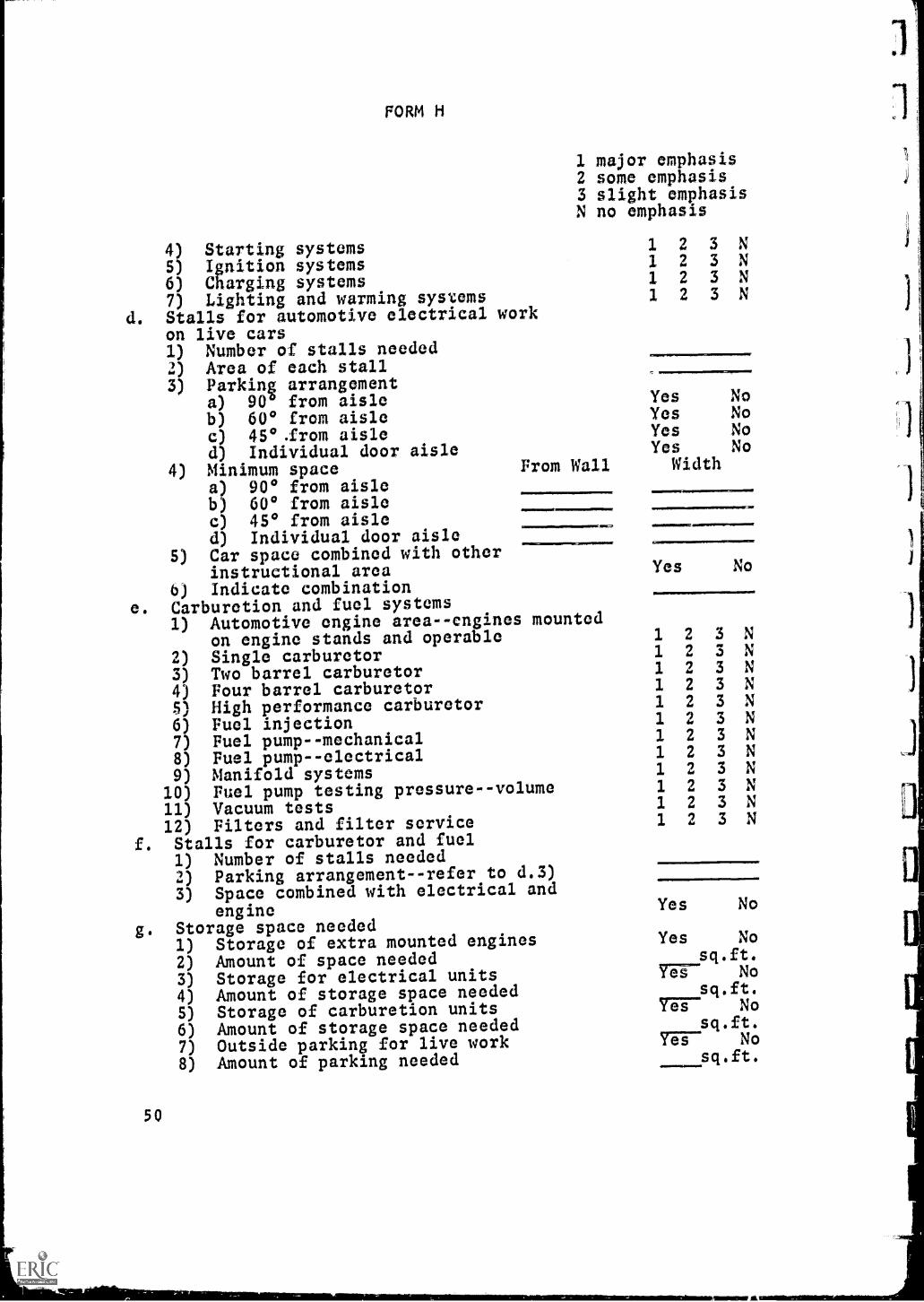
FORM H
4) Starting systems5) Ignition systems6) Charging systems7) Lighting and warming systemsStalls for automotive electrical workon live cars1) Number of stalls needed2) Area of each stall3) Parking arrangement
a) 90° from aisleb) 60* from aislec) 45*.from aisled) Individual door aisle
4) Minimum spacea) 90* from aisleb) 60* from aislec) 45* from aisled) Individual door aisle
5) Car space combined with otherinstructional area
6) Indicate combinatione. Carburetion and fuel systems
1) Automotive engine areaengines mountedon engine stands and operable
2) Single carburetor3) Two barrel carburetor4) Four barrel carburetorS) High performance carburetor6) Fuel injection7) Fuel pump--mechanical8) Fuel pumpelectrical9) Manifold systems
10) Fuel pump testing pressurevolume11) Vacuum tests12) Filters and filter serviceStalls for carburetor and fuel
1) Number of stalls needed2) Parking arrangement--refer to d.3)
3) Space combined with electrical andengine
Storage space needed1) Storage of extra mounted engines
2) Amount of space needed3) Storage for electrical units4) Amount of storage space needed5) Storage of carburetion units6) Amount of storage space needed7) Outside parking for live work8) Amount of parking needed
1 major emphasis2 some emphasis3 slight emphasisN no emphasis
From Wall
VIIIIIIMIERIMNIEPPIMINI1111.
50
1111
22
2
2
333
3
YesYesYesYes
Width
NoNoNoNo
Yes No
1 2 3 N1 2 3 N1 2 3 N1 2 3 N1 2 3 N1 2 3 N1 2 3 N1 2 3 N1 2 3 N1 2 3 N1 2 3 N1 2 3 N
Yes No
Yes Nosq.ft.
MT- No
76?- Nosq.ft.
7-6F- Nosq.ft.

FORM H
Spatial relationships to other areas
a. Accessibility to chassis dynamometer Yes No
b. Other (specify)
Equipment
a. Dynamometer--engine Yes No
Number of engine dynamometers required
b. Engines mounted in stands 7-7-1VNumber of mounted engines required
c. Work benches in engine area1) Standard free standing service benches P A NA
2) Wall hung service benches P A NA
3) Area of bench spaces needed4) Relationship of bench areas to engine
area--describe
5) IsspErrE'rif"-Fai-E--eatiolicareastoservice
stalls--describe
ElecTREUT-FITUTWEI1) Master automotive engine analyzer P A NA
Number of master engine analyzersneeded
2) Generatoralternatorregulator tester P A NA
Numbrwr of generator, alternator andregulator testers needed
3) Distributor testerNumber of distributor testers needed
4) Portable starterbattery tester 1 A NANumber of starter--battery tastersneeded
5) Combustion analyzer P A NA
Number of combustion analyzersneeded
6) Portable alternator--generator test
stand P A NANumber of portable alternator,generator test stands needed
7) Portable ignition analyzer P A NA
Number of ignition analyzers needed
8) Coil, condenser tester P A NA
Number of coil condenser testersneeded
9) Volt, ampere tester A A'Number of volt, ampere testers needed
51

FORM H
10) Electrical unit with separateremovable meters: A.V.R., Dwell,Tach, Combustion, Volt-amp.a) Indicate specific meters needed
in unit
b) Nt-TnEZT-Firaoveurrnsneee-11) Fast charge battery charger
Number of fast charge batterychargers needed
12) Slow charge battery chargersNumber of slow charge batterychargers needed
13) Combination fast-slow charge batterychargers
Number of combination fast-slowcharge battery chargers needed
14) Spark plug cleanerNumber of spark plug cleanersneeded
15) Ignition simulatorNumber of ignition simulatorsneeded
e. Engine equipment1) Portable crane P A NA
a) Capacity of crane(1) 2000ff(2) 1000#
b) Number needed2) Portable engine stands
Number of portable engine standsneeded
3) Honing machine P A NA
Number of honing machines needed4) Cap and rod grinder P A NA
Number of cap and rod grindersneeded
5) Rod aligner P A NANumber of rod aligners needed
6) Valve refacer P A NA
Number of valve refacers needed
7) Valve reconditioning shop (seats andvalves) P A NA
Number of valve reconditioningshops needed
8) Hydraulic press P A NA
Number of hydraulic presses needed
J) Three ton arbor press P A NA
Number of arbor presses needed10) Engine cleaning machine
a) Number of engine cleaning machinesneeded
b) State type and size
52
P A NA
FMNTTr A NA
P A NA
Yes NoYes No

FORM H
Environmental factors
a. Aesthetic. Factors to be considered in the aestheticUBT417-517e colors, light, style of architecture, design
and the like. Indicate any special aesthetic considera-
tions important to the planning of the engine, electrical,
and fuel laboratory area(s).
re-i73717 actors to e cons ere in t is category IncETTiMperature, radiant temperature, relative humidity,
and ventilation. Indicate any special considerations
important to the planning of the engine, electrical, and
fuel laboratory area(s).
c. proper y contro e an a ance v sua
FIVI-Whment is important. The visual environment affects
such things as accuracy in perception, attention to tasks,
and speed of performance. Indicate any special factors
which should be taken into account in planning the visual
environment of the engine, electrical, and fuel laboratory
area(s).
1111111110111111=1
ety. n p anning scloo ui ings, sa ety or stu ents
and instructors is of prime concern. Indicate any special
safety considerations which .ave implications of the
engine, electrical, and fuel laboratory area(s).
7. Vertical instructional surfaces
a. Chalkboardl) Wall-mounted
Number of lineal feet2) Portable
a) Number of lineal feetb) Provision for storage
b. Tack boardNumber of lineal feet
c. PegboardNumber of lineal feet
8. Special utilities needed
Yes NoP A NA
P A NA
Yes NoYes No
Yes No
53

FORM H
a. Electricity1) Generator--alternator tester
a) 110V 60C 1 Phase Yes No
b) 220V 60C 1 Phase Yes No
c) 220V 60C 3 Phase Yes No
2) Location of 110V outlets for electricaltest units (list)a)b)c)d)e)f)
3) Location o it out ets or ot ermechanical equipment (list)a)b)c)d)e)
4) Special lighting requirements (specify)
a)b)c)d)e)
5) ElecfFTEETUSERUUTTURTor dynamometer.If electrical specify special concerns todissipate power generated--or heatgenerated.
!MVO
b. Water1) Water supply to engine dynamometer if
absorption unit is water cooled Yes No
2) Minimum size of water sutiply to engine
dynamometer3) Minimum size of drain to dispose of
water from the engine dynamometer4) Water supply to mounted engine units
if cooled by water from the line Yes No
5) Size of supply to each engine stationif used
6) Size and disposition of return water(i.e., drain to floor drain to keep size
floor drain clean) disposition
c. Gasoline1) Gasoline supply to dynamometer Yes No
2) Gasoline supply to mounted engines Yes No
3) Limit of storage capacity within thelab in keeping within local codes gal.
4) Distribution of gasoline to units
..4,0=1011.11.1t
51t

FORM II
a) Pumpb) Gravityc) Underground
5) Description of gasoline system
Exhaust system1) Exhaust from engine mounted in
dynamometer Yes No
2) Exhaust from mounted engines Yes No
a) Overhead P A NA
b) In the floor P A NA
c) Connected to central system P A NA
d) Separate system P A NA
3) Describe how outlets will be connected
to:a) Enginesb) Dynamometerc) Cars in stalls
e. Installation1) Special footing needed for engine
dynamometer Yes No
2) Describe special footing and sizeand location for:a) Dynamometer
P A NAP A NAP A NA
b) EITTEFEERUYETEEFEaEY7517EaTacentto absorption unit
c) Other special conditions to be metconcerning floor weight, concealedelements in the floor, or unitsattached to the wall
9. Minimum space requirements in square feet
a. Floor area needed for the entire engine,electrical and fuel laboratory
b. If distinct space divisions are desiredaccording to function, give minimum floor
area requirements in square feet for each
of the following areas if included in thedesired program:1) Dynamometer area2) Mounted engine area3) Engine area for live cars
55

4)
5)
FORM H
Engine area for benchesElectrical area
0) Storage area--engines7) Storage area--electrical8) Storage area--carburetor9)
10)11)12)
10. Other important factors to be considered in the planning of
the automotive engine, electrical and fuel laboratory area(s)
are:
VIMI111.111......
56
.....m..

FORM I
DESCRIPTION OF ALIGNMENT AND STEERING LABORATORY AREA(S)TO BE USED PRINCIPALLY FOR ACTION LEARNING
1 major emphasis2 some emphasis3 slight emphasisN no emphasis
1. The alignment and steering laboratory shouldba planned:
a. As an independent unit(s) Yes No
b. In combination with seminar area(s) Yes No
c. In combination withlaboratory area(s) '-W6-6-13:75r7 Yes No
d. As a part of a complete automotiveservice laboratory Yes No
e. As a combination of separate unitsi.e., alignment, steering, balancing Yes No
f. In combination with lecture/demonstrationarea(s) Yes No
g. As an area within a single multi-usepurpose area Yas No
2. Student capacity required for scheduledactivities (see Form E)
3. Student and instructor activities in variousareas involved in the alignment and steeringarea(s).Indicate the extent to which each activitywill occur.
a. Alignment space1) Check and adjust camber2) Check and adjust caster3) Check and adjust toe in
4) Check and correct steering geometry(toe out on turns)
5) Check and correct rear wheel camber6) Check and correct rear wheel toe7) Check and correct rear wheel track8) Check suspension specifications9) Other (specify)
b. Steering space1) Disassemble, assemble and identify
all parts of each type of steeringgear
2) Disassemable, assemble and identifyparts of power steering units
3) Adjust each steering gear worked on
4) Adjust steering gear and all linkageon live automobile
5) Adjust wheel to "straight ahead" position
c. Wheel balancing
1 2 3 N1 2 3 N1 2 3 N
1 2 3 N1 2 3 N1 2 3 N1 2 3 N1 2 3 N1 2 3 N
1 2 3 N
1 2 3 N1 2 3 N
1 2 3 N1 2 3 N
57

FORM I
1 major emphasis2 some emphasis3 slight emphasisN no emphasis
1) Demonstrate wheel balancing using theon-the-car balancer 1 2 3 N
2) Demonstrate wheel balancing using theoff-the-car balancer 1 2 3 N
3) Balance wheels using the on-the-carbalancer 1 2 3 N
4) Balance wheels using the off-the-carbalancer (dynamic) 1 2 3 N
5) Balance wheels using the off-the-carbalancer (bubble) 1 2 3 N
6) Correction of out of balance conditionsby truing tire 1 2 3 N
4. Spatial relationships desired
a. Areas within the alignment and steeringlaboratory area(s) (e.g., alignment rackadjacent to wheel balancing area)1)2)
3)
4)b. LaboTatiFfrairraiirTieas
(e.g., alignment and steering laboratoryadjacent to building delivery area)1)2)
3)
4)
S. Equipment
a. Pit installed alignment rack P A NA1) Number required2) Other (specify)
b. Above floor alignment rack P A NA1) Number required2) Optical system of amplification P A NA3) Electrical system of amplification P A NA4) Mechanical system of amplification P A NA5) Other (specify)
c. Portable alignment system P A NA1) Number required2) Optical system P A NA3) Mechanical system P A NA4) Bubble gage system P A NAS) Other (specify)
d. Wheel balancing equipment P A NA1) On the car balancer P A NA
5 8

r17,4,0, r,o4.
FORM I
2)3)
1 major2 some3 slightN no
Number neededType of balancera) Electronicb) Shifting weightsc) Stroboscopic
emphasisemphasis
emphasisemphasis
YesYesYes
NoNoNo
4) Off-the-car balancera) Static P A NAb) Dynamic P A NA
5) Number of off-the-car balancers needed6) Tire changing equipment P A NA
a) Electric 1 2 3 Nb) Air operated 1 2 3 N
7) Power equirementsa) 110Vb) 220Vc) Shop air pressure
YesYesYes
NoNoNo
8) Other (specify)
6. Environmental factors
a. Aesthetic. Factors to be considered in the aestheticdomain are colors, light, style of architecture, designand the like. Indicate any special aesthetic considera-tions important to the planning of the alignment andsteering laboratory area.
b. Aerial. Factors to e consi ere in t is category inch.' eair temperature, radiant temperature, relative humidity,and ventilation. Indicate any special considerationsimportant to the planning of the alignment and steeringlaboratory area.
c. Visual. A properly controlle an alance visualenvironment is important. The visual environment affectssuch things as accuracy in perception, attention to tasks,and speed of performance. Indicate any special factorswhich should be taken into account in planning the visualenvironment of the alignment and steering laboratory area.
d. Sonic. Factors to e consi erea in t is category inclu eFaathings as acoustical requirements and sound systems.
5 9

FORM I
Indicate any special considerations important to the
planning of the alignment and steering laboratory area.
e. Safety. In planning a school building safety for studentsand instructors is of prime concern. Indicate any specialsafety considerations which have implications for designof the alignment and steering laboratory area.
7. Vertical instructima1 surfaces
a. Chalkboard1) Wall-mounted
Number of lineal feet2) Portable
a) Number of lineal feetb) Provision for storage
b. Tack boardNumber of lineal feet
c. PegboardNumber of lineal feet
8. Special utilities needed (describe)
a. Electricity
b. Water
C. as
d. Compressed air
e. Other (specify)
60
Yes NoP A NA
P A NA
Yes NoYes No
Yes No

FORM I
9. Minimum floor areas in square feet (optional)
a. Floor area in square feet desired for entire
alignment and steering laboratory area sq.ft.
b. If distinct space Axisions within the
alignment and steering laboratory area
are desired according to function, give
minimum floor areas for the various areaswithin the total laboratory area.
1)sq.ft.
2)sq.ft.
3)sq.ft.
4)sq.ft.
10. Other important factors to be considered in the planning of
the alignment and steering laboratory area(s) are:
61

FORM J
DESCRIPTION OF BRAKE AND BRAKE POWER SYSTEMS LABORATORY AREA(S)TO BE USED PRINCIPALLY FOR ACTION LEARNING
1 major emphasis2 some emphasis3 slight emphasisN no emphasis
1. The brake and brake power systems laboratoryshould be planned:
a.
b.As an independent unit(s)In combination with lectuye/demonstration
Yes No
c.area(s)In combination with
Yes No
laboratory area(s) (specify) Yes Nod. In combination with seminar area(s) Yes No
e. As an area within a single multi-use area Yes No
2. Student capacity required for scheduledactivities (see Form E)
3. Student and instructor activities and physicalarrangements in various space divisions withinthe brake service and brake power systemslaboratory area(s).
a. Minor brake service area1) Check pedal height and travel2) Check condition of hydraulic lines3) Remove wheels and check condition
of brake lining and drums4) Check condition of U-bolts5) Check condition of shock absorbers6) Check condition of rubber bushings
and ball joints7) Check fluid level of master cylinder8) Other (specify)
b. Brake adjustment area1) Fixed anchor type--adjustment2) Huck brake--adjustment3) Wagner brake--self-centering adjustment4) Center plane total contact adjustment5) Bendix self-centering adjustment6) Bendix duo-servo--adjustment7) Disc brake
a) Chrysler self-adjustingb) Caliper disc-adjusting
8) Adjust parking brake--real wheel9) Adjust parking brake--transmission
c. Brake overhaul area1) Recondition drums (turn drums)2) Recondition drums (grind drums)3) Remove and replace linings
1 2 3 N1 2 3 N
1 2 3 N1 2 3 N1 2 3 N
1 2 3 N1 2 3 N
1 2 3 N1 2 3 N1 2 3 N1 2 3 N1 2 3 N1 2 3 N
1 2 3 N1 2 3 N1 2 3 N1 2 3 N
1 2 3 N1 2 3 N1 2 3 N

FORM J
4) Grind shoes to fit drumsd. Hydraulic reconditioning area
1) Remove, clean and inspect wheel7ylinders
2) Rebuild wheel cylinders3) Remove, clean and inspect master
cylinders4) Rebuild mast:I.' cylinders5) Reassemble brake components and
mount on vehicle6) Flush and refill hydraulic system7) Major brake adjustment
e. Entire brake system area1) Road test2) Dynamometer test
f. Service brake power area1) Disassemble, replace seals and
reassemble power unit2) Replace entire unit with rebuilt kit
g. Stalls for brake service and brakebooster systems1) Number of stalli needed2) Area of each stall3) Parking arrangement
a) 900 from aisleb) 60° from aislec) 45° from aisled) Individual door aisle
4) Minimum space for stalls for brakeservicea) 90° from aisleb) 60° from aislec) 45° from aisied) IndivIdual door aisle
Brake service aisles combined withother instructional laboratory area(s)Stall for brake tester/dynamometerSpace required for brake tester and/ordynamometerStorage space neededa) Storage for laboratory brake componentsb) Storage for brake components (parts room)c) Square foot area of parts room shelf
spaceRelationship to other areas of the laboratory
5)
6)7)
8)
9)
1 major emphasis2 some emphasis3 slight emphasisN no emphasis
1 2 3 N1 2 3 N
1 2 3 N1 2 3 N
1 2 3 N1 2 3 N1 2 3 N
1 2 3 N1 2 3 N
1 2 3 N1 2 3 N
Yes NoYes NoYes NoYes No
Yes NoYes No
Yessq.ft.
No
sq.ft.
63

FORM J
4. Spatial relationships desired
a. Areas within the brake and power systemslaboratory areas (e.g., brake service areaadjacent to shoe grinder area)1)2)3)
4)
b. Brake and power systems la oratory areasto other building areas (e.g., brake andpower systems laboratory adjacent todelivery areas)1)2)3)4)
5. Equipment
a. Brake drum reconditioning1) Complete brake shop P A NA
2) Brake drum lathe P A NA
3) Brake drum grinder P A NA
4) Number of units requiredb. Brake shoe reconditioning
1) On-the-car shoe grinder P A NA
2) Off-the-car shoe grinder P A NA
3) Cam shoe grinder P A NA
4) Brake lhoe riviting machine P A NA
5) Brake shoe bonding machine P A NA
6) Number of brake shoe grinders required7) Number of brake lining installing
machines requiredc. Benches for brake service and brake booster
service needed1) Wall-hung-benches P A NA
2) Standard--free-standing benches P A NA
3) Benches with storage cabinets attached P A NA
4) Number of benches requiredd. Brake testing equipment
1) Dynamometer P A NA
2) Drive over tester P A NA
3) Other (specify)4) Area needed for brake tester sq.ft.
e. Relationship of equipment area(s) toother area(s) in laboratory1) Relationship to alignment area(s)
2) Relationship to general service area(s)

3) Relationship of brake service stalls to
brake shop and brake service bench area(s)
6. Environmental factors
a. Aesthetic. Factors to be considered in the aesthetic
domain are colors, light, style of architecture, design
and the like. Indicate any special aesthetic considera-
tions important to the planning of the brake and power
systems laboratory area.
b. Aerial. Factors to e consi ere in t is category inclu e
air temperature, radiant temperature, relative humidity,
and ventilation. Indicate any special considerations
important to the planning of the brake and powers systems
laboratory area.
c. isual. A properly control e an alance visual
environment is important. The visual environment affects
such things as accuracy in perception, attention to tasks,
and speed of performance. Indicate any special factors
which should be taken into account in planning the visual
environment of the brake and power systems laboratory area.
d. Sonic. Factors to be considered in this category include
galthings as acoustical requirements and sound systems.
Indicate any special considerations important to the
planning of the brake and power systems laboratory area.
e. a ety. n planning a sc ool ui ing sa ety fin' students
and instructors is of prime concern. Indicate any special
safety considerations which have implications for design
of the brake and power systems laboratory area.
65

FORM J
7. Vertical instructional surfaces
a. Chalkboard1) Wall-mounted
Number of lineal feet2) Portable
a) Number of lineal feetb) Provision for storage
b. Tack boardNumber of lineal feet
c. PegboardNumber of lineal feet
8. Special utilities needed (describe)
a. Electricity
b. Water
c. Gas
d. Compressed air
e. Other (specify)
9. Minimum floor areas in square feet (optional)
a. Floor area in square feet desired for theentire brake and power systems laboratoryarea's)
b. If distinct space divisions within thebrake and power systems laboratory areaare desired according to function, giveminimum floor areas for the variousareas within the total laboratory area.1)2)
3)
4)
Yes NoP A NA
P A NA
Yes NoYes No
Yes No
sq.ft.
sq.ft.
sq.ft.sq.ft.
10. Other important factors to be considered in the planning of thebrake and power systems laboratory area(s) are:
66

FORM K
DESCRIPTION OF DRIVE LINE AND TRANSMISSION LABORATORY AREA(S)
TO BE USED PRINCIPALLY FOR ACTION LEARNING
1 major emphasis2 some emphasis3 slight emphasisN no emphasis
1. The drive line and transmission laboratoryarea(s) should be planned:
a. As an independent unit(s) Yes No
b.c.
As a combination with other unit(s)As a part of a ccmplete automotive
Yes No
d.
service laboratoryAs two separate laboratories (transmission
Yes No
e.
and/or drive line)In combination with lecture/demonstration
Yes No
laboratory area(s) Yes No
f. As an area within a single multi-use area Yes No
2. Student capacity required for scheduledactivities (see Form E)
3. Student and instructor activities, physicalarrangements, equipment, and space divisionswithin the drive line and transmission area(s).Indicate the extent to which each of the followingwill occur.a. Transmission--standard
1) Remove standard transmission from
vehicle2) Rebuild transmission3) Rebuild standard clutch4) Install standard transmission5) Simulate above 'operations on
laboratory unitsb. Transmissions--automatic
1) Remove automatic transmission from
vehicle2) Rebuild automatic transmission3) Install automatic transmission4) Remove transmission, install new
seals5) Adjust linkage on automatic
transmission6) Perform any or all of the operations
on automatic transmissions in a speciallaboratory on laboratory models
c. Automatic transmission--dynamometer1) Install automatic transmission on
transmission dynamometer2) Check performance of automatic
transmission dynamometer
1 2 3 N1 2 3 N1 2 3 N1 2 3 N
1 2 3 N
1 2 3 N1 2 3 N1 2 3 N
1 2 3 N
1 2 3 N
1 2 3 N
1 2 3 N
1 2 3 N
67

FORM K
1 major emphasis2 some emphasis3 slight emphasisN no emphasis
d. Drive line1) Remove drive shaft from vehicle 1 2 3 N2) Rebuild universal joints on drive
shaft 1 2 3 N3) Install drive shaft on vehicle 1 2 3 N
e. Rear axle1) Remove rear axle from vehicle 1 2 3 N2) Rebuild and/or repair rear axle 1 2 3 N3) Install rear axle in vehicle 1 2 3 N
f. Stalls needed for drive line service1) Number of stalls needed2) Area of each stall3) Parking arrangement
a) 90° from aisle Yes Nob) 60° from aisle Yes Noc) 45° from aisle Yes Nod) Individual door aisle Yes No
4) Minimum space needed for drive lineservicea) 900 from aisle Xb) 60° from aisle Xc) 45' from aisle Xd) Individual door aisle X
5) Drive line service aisle(s) combinedwith other instructional area(s) Yes No
6) Indicate combination of area(s)
7) Storage space needed for "mock-up"unit(s) Yes No
8) Indicate total storage space needed X
4. Spatial relationships desired
a. Areas within the drive line and transmissionlaboratory areas (e.g., parking stall areaadjacent to drive line area)112)
3)
4)b. Drive line and tTansmission laboratory areas
to other building areas (e.g., drive lineand transmission laboratory adjacent todelivery area)1)2)
3)
5. Environmental factors
68
(

4,1IMiCOMMINNIMIINI..14
FORM K
a. Aesthetic. Factors to be considered in the aesthetic
domain are colors, light, style of architecture, design
and the like. Indicate any special aesthetic considera-
tions important to the planning of the drive line and
transmission laboratory area.
b. Aerial. Factors to be considered in this category include
aiTTaperature, radiant temperature, relative humidity,
and ventilation. Indicate any special considerations
important to the planning of the drive line and trans-
mission laboratory area.
c. Visual. A properly controlled and balanced visualenvironment is important. The visual environment affects
such things as accuracy in perception, attention to tasks,
and speed of performance. Indicate any special factors
which should be taken into account in planning the visual
environment of drive line and transmission laboratory area.
d. Sonic. Factors to be considered in this category include
REFthings as acoustical requirements and sound systems.
Indicate any special considerations important to the
planning of the drive line and transmission laboratory
area.
e. a ety. n p anning a sc ool uil ing safety for students
and instructor., is of prime concern. Indicate any special
safety considerations whicl- have implications for design
of the drive line and transmission laboratory area.
. Vertical instructional surfaces
a. ChalkboardYes No
1) Wall-mounted P A NA
Number of lineal feet
2) Portable P A NA
a) Number of lineal feetb) Provision for storage Yes No
69

FORM K
b. Tack board Yes NoNumber of lineal feet
c. Pegboard Yes NoNumber of lineal feet
7. Minimum floor areas in square feet (optional)
a. Floor area in square feet desired for thisentire drive line and transmission labora-tory area(s).
b. If distinct space divisions are desiredaccording to function, give minimum floorareas for the various areas within the totallaboratory area.1) sq.ft.2) sq.ft.
3) sq.ft.
4) sq.ft.
8. Other important factors to be considered in the planning ofthe drive line and transmission laboratory area(s) are:
70
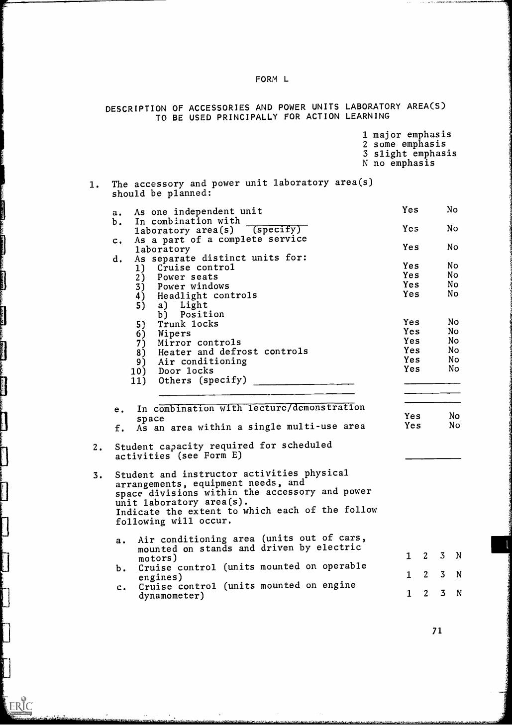
FORM L
DESCRIPTION OF ACCESSORIES AND POWER UNITS LABORATORY AREA(S)TO BE USED PRINCIPALLY FOR ACTION LEARNING
1 major emphasis2 some emphasis3 slight emphasisN no emphasis
1. The accessory and power unit laboratory area(s)should be planned:
a. As one independent unit Yes No
b. In combination withlaboratory area(s) (specify) Yes No
c. As a part of a complete servicelaboratory Yes No
d. As separate distinct units for:1) Cruise control Yes No
2) Power seats Yes No
3) Power windows Yes No
4) Headlight controls Yes No
5) a) Lightb) Position
5) Trunk locks Yes No
6) Wipers Yes No
7) Mirror controls Yes No
8) Heater and defrost controls Yes No
9) Air conditioning Yes No
i 10) Door locks Yes No
1
11) Others (specify)
e. In combination with lecture/demonstrationspace Yes No
f. As an area within a single multi-use area Yes No
2. Student capacity required for scheduledactivities (see Form E)
3. Student and instructor activities physicalarrangements, equipment needs, andspace divisions within the accessory and powerunit laboratory area(s).Indicate the extent to which each of the followfollowing will occur.
a. Air conditioning area (units out of cars,mounted on stands and driven by electricmotors) 1 2 3 N
b. Cruise control (units mounted on operableengines) 1 2 3 N
c. Cruise control (units mounted on enginedynamometer) 1 2 3 N
71

FORM L
1 major emphasis2 some emphasis3 slight emphasisN no emphasis
d. Other accessoriesseat, window, etc.(units mounted and operable) 1 2 3 N
e. Benches needed for unit overhaul Yes No
Number of benches neededf. Stalls needed for accessory work on
live vehicles Yes No
1) Number of stalls needed2) Parking arrangement
a) 900 from aisle Yes No
b) 600 from aisle Yes No
c) 450 from aisle Yes No
d) Individual door aisle Yes No
3) Minimum space required for stallsa) 900 from aisle xb) 60° from aisle xc) 450 from aisle xd) Individual door aisle x
4) Car space combined with otherinstructional area(s) Yes No
Indicate combination withlaboratory unit(s) (specify)
5) Storage space needed6) a) Storage space for laboratory
units--operable Yes Nob) Indicate total storage space
needed sq.ft.7) Indicate total outside parking area
needed sq.ft.g. Relationship to other automotive
laboratory area(s)1) Accessibility to chassis dynamometer Yes No2) Accessibility to electrical area Yes No3) Accessibility to engine area
(mounted units) Yes Noh. Equipment needed
1) Air conditioninga) Freon testing and charging units Yes Nob) Number of units needed
2) Benches in the work areaa) Free-standing service benches P A NAb) Wall-hung service benches P A NAc) Other (describe)
3) Relationship of bench area to accessoryservice stalls (describe)
4) Relationship of bench area to otherlaboratory area(s) (describe)
72

FORM L
5) Storage cabinets for extra laboratoryaccessory units Yes No
Total amount of storage space neededi. Electrical requirements
1) Electrical outlets to provide power todrive automotive air conditioning unitsmounted in laboratory Yes No
2) Number of electrical outlets needed3) Location of electrical outlets
a)b)c)d)
4) Powera) 110V--1 Phase Yes No
b) 220V--1 Phase Yes No
c) 220V--3 Phase Yes No
4. Spatial relationships desired
a. Areas within the accessories and power unitslaboratory area(s) (e.g., parking areaadjacent to bench area)1)2)
3)
4)
b. Laboratory areas to ot er uil ing areas(e.g., accessories and power unitslaboratory adjacent to delivery area)1)
2)
3)
4)
5. Environmental factors
a. Aesthetic. Factors to be considered in the aestheticdomain are colors, light, style of architecture, designand the like. Indicate any special aesthetic considera-tions important to the planning of the accessories andpower units laboratory area.
b. Aerial, actors to e consi ere in t is category inc u e
air temperature, radiant temperature, relative humidity,and ventilation. Indicate any special considerationsimportant to the planning of the accessories and powerunits laboratory area.
73

c. Visual. A properly controlled and balanced visualenvironment is important. The visual environment affectssuch things as accuracy in perception, attention to tasks,and speed of performance. Indicate any special factorswhich should be taken into account in planning the visualenvironment of the accesFL.ies and power units llboratoryarea.
d. Sonic. Factors to be considered in this category includeFLTEEthings as acoustical requirements and sound systems.Indicate any special considerations important to theplanning of the accessories and power units laboratoryarea.
e. Safety. In planning a school building safety for studentsand instructors is of prime concern. Indicate any specialsafety considerations which have implications for designof the accessories and power units laboratory area.
6. Vertical instructional surfaces
a. Chalkboard Yes No
1) Wall-mounted P A NANumber of lineal feet
2) Portable P A NAa) Number of lineal feetb) Provision for storage Yes No
b. Tack board Yes NoNumber of lineal feet
c. Pegboard Yes NoNumber of lineal feet
7. Minimum floor areas in square feet (optional)
a. Floor area in square feet desired for thisentire accessories and power units laboratoryarea
b. If distinct space division: are desiredaccording to function, give minimum floorareas for the various areas within thetotal laboratory area.
74

1)
2)3)
4)
FORM L
sq.ft.sq.ft.sq.ft.sq.ft.
8. Other important factors to be considered in the planning of
the accessories and power units laboratory area(s) are:
,,e1/,117
75

FORM M
DESCRIPTION OF OTHER PLANNING CONSIDERATIONENTIRE AUTOMOTIVE LABORATORY BUT NOT DIRE
WITH ONLY ONE PARTICULAR AREA TO BE USED F
1. Tool and parts crib
a. Tool crib and parts department comin one room
b. If yes--give total sizec. If no--give size of each
1) Tool crib2) Parts department
d. Location with respect to othearea(s)
S RELATED TO THECTLY ASSOCIATED
OR ACTION LEARNING
bined
r laboratory
e. Arrangement of-counter1) Dutch door2) Open counter
2. Oil storage area--size
3. Exhaust systems
a,. For individual stallb. C.F.M. required forc. Single or dual connd. Exhaust systems foe. Size of connectiof. C.F.M. exhaustedg. Total number ofh. Total C.F.M. toi. Total numberj. Total C.F.M.
areak. Separate ex1. Exhaust sym. Engine dynn. General v
area
4. Hoists
a. Totalb. Type
1)
2)
3)
c. L
76
each stallections
r mounted enginesn for each engine--each outletstall connectionsbe exhausted
f engine connectionsto be exhausted from engine
haust system for each area abovestem combined into oneamometer exhaustentilation of entire laboratory
number of hoists neededof hoists to be usedTwo post in-line frame contactSingle post frame contactSingle post wheel contact
ocation of hoists1) Alignment area2) Brake service area3) Transmission area4) Lubrication area5) Other (specify)
Yes Nosq.ft.
sq.ft.sq.ft.
Yes NoYes No
Yes
Yes
sq.ft.
No
No
Yes NoYes No
Yes No
P A NAP A NAP A NA
P A NAP A NAP A NAP A NA

FORM M
d. Other conside.rations pertaining to type ofhoist or location
5. Engine and parts cleaning area
a. Location in general service area orcleaning area (specify)
b. Heat and power requirements for enginecleaning equipment1) Gas Yes No
2) Steam Yes No
3) Electricity--110V--1 Phase Yes No
4) Electricity--220V--1 Phase Yes No
5) Electricity--220V--3 Phase Yes No
6) Shop air pressure Yes No
c. Special considerations for installationof engine cleaning tank (i.e., air toimpeller bearing) (specify)
d. Location of small parts cleaning equipment(specify)
e. Heat and/or power needed for small partswasher1) Shop air pressure Yes No
2) Reduced air pressure Yes No3) Electricity--110--1 Phase Yes No
6. Wash rack area for entire vehicle
a. Size of wash rack sq.ft.
b. High pressure cleaning equipment Yes No
c. Power required for high pressure unit1) Air Yes No
2) Electricity 110V--1 Phase Yes No
3) Other (specify)
7. Floor drains
a. Floor drains for each stall Yes No
b. Trench drain serving entire laboratory Yes No
c. Sludge and oil interceptor Yes No
d. Separate drain for alignment pit Yes No
8. Lubrication equipment
a. Number of lubrication stations neededb. Type of lubrication equipment
77

, auasesumas
FORM M
1) Overhead reels Yes No
2) Island dispensers Yes No
3) Other (specify)
c. LocaEia of lubrication equipment (specify)
d. Lubrication equipment combined with hoistequipment used for other purposes (state
combination)
9. Service desk and customer waiting area
a. Location (specify)
b. Size of area required (specify)
10. Air compressor
a.
b.c.
Location (specify)
Size C.F.M. neededPower required1) 110V--1 Phase Yes No
d.
2) 220V--3 PhaseLocation of air outlets
Yes No
1) Each bench Yes No
2) Spark plug cleaner Yes No
3) Parts cleaning area Yes No
4) Air operated car wash Yes No
5) Grease dispensing equipment Yes No
6) Air operated hoists Yes No
e.7) Other (specify)Location of water outlets1) Parts cleaning area Yes No
2) General around-wall space(state spacing)
3) Mounted engine area Yes No
4) Other (specify)
f.Yes NoGasoline storage
Describe distribution system to enginearea(s) after consultation with local
78
fire authorities

FORM N
11. Laboratory lighting
a. General illumination of laboratory area(s)area(s) foot candles
b. Portable illumination Yes No
d. 1) Reel type drop cords Yes No
2) Over each stall Yes No
3) Over each hoist Yes No
4) Others (describe)
12. Laboratory doors
a. Size 12 x 12 Yes No
b. Size 12 x 14 Yes No
c. Other (specify)d. Power operated
1) Location of power operatingcontrol buttons (state)
2) Other (specify)
13. Safety
a. Master shut off for all air operatedequipment Yes No
b. Master shut off for all electricallyoperated equipment Yes No
c. Location of master controls (state)
79

FORM N
ADDITIONAL PLANNING CONSIDERATIONS
Other important factors to be considered in the rwerall planning
and design of instructional areas for the planned automotive
service occupational preparation program(s) are:
80

PART IN'
ANNOTATED BIBLIOGRAPHY
GENERAL FACILITY PLANNING
American Association of School Administrators. PlanningAmerica's School Buildings. Washington, D. C.: TheAssociation, 1960.
Contributors to this publication were teachers, supervisors,administrators, architects, engineers, school board members,and school plant planning specialists. In addition tobackground material on school house construction, the bookdeals with specific topics including school surveys,analysis and computation of space and facility needs,enrollment projections, building designs, site selection,finance, and building maintenance and operation. Manypictures and illustrations are found, along with sampleforms and outlines, which can be used in the facility planningprocess. No special consideration is given to uniqueproblems faced in the planning for vocational and technicaleducation facilities.
Boles, Harold W. Step by Step to Better School Facilities.New York: Holt, Rinehart, and Winston, 1965.
A textbook on overall planning procedures for new andimproved school facilities. The typical topics (schoolsurveys, building planning, site selection and acquisition,architectural planning, contracting for construction,and the equipping 'Ind furnishing of buildings) are covered.The only mention of vocational schools is on page 270where the author quotes from another source:
Vocational training should be de-emphasized in theschools since this training often becomes obsoletebefore it can be used; also, special "trade" andIf vocational" schools should be discontinued, unlessthe vocational curriculum is liberal in approach andbroad in character. Such schools are often used asdumping grounds for students who are not wanted else-where and often more than custodial care is providedfor them. When more is provided, the skills taughtare frequently too partial in nature.
81

Conrad, M. J. Four Steps to New Schools. Columbus, Ohio:Educational Administration and Facilities Division of theBureau of Educational Research and Service. The OhioState University.
A book prepared for the inexperienced school planner. Theauthor emphasizes that a school building is an educationaltool and should be designed to do the job they are intendedto do. The four steps discussed are: 1) district-widebuilding survey; 2) educational planning; 3) architecturalplanning and construction; and 4) moving in and settlingdown. A glossary of important terms used in plant planningis located in the back of the book.
Conrad, M. J.; Wohlers, E. E.; and Griggs, Norman. School Plant
Plannin : An Annotated Biblio.ra h Columbus, Ohio: The
A ministration an Facilities Unit, School of Education, TheOhio State University, 1968.
A compilation of references in the following categories:general references; periodicals; overview of school plantfield; district-wide building survey; educational planning;the architect and his work; moving in and settling down;and related topics.
Finchum R. N. Extended Use of School Facilities. Washington,D. C.: U. S. Department of Health, Education, and Welfare,1967.
This manual is intended to assist officials of school dis-tricts who are planning programs for maximum use of schoolproperties and who must develop policies and regulations forefficient management of such programs. Various schedules offacility use are illustrated for nine different school systems.
Green, Alan C. Educational Facilities with New Media. WashingtonD. C.: Department of Audiovisual Instruction, NationalEducation Association,1966.
This work is designed to meet the needs of three distinctgroups interested in providing educational facilities. Report
A: "A Guide for Policy Makers" is directed to boards, adminis-trators, planning committees, and institutional planners.Report B: "A Guide for the Design of Professions" is designedfor architects, planners, and design specialists and planningcommittees; and Report C: "A Technical Guide" is intended fordesign-architects, engineers, equipment and furniture suppliers,
and media specialists.
National Council on School House Construction. NCSC Guide for Plan-
ning Plants. East Lansing, Michigan: The Council, 1964.
A basic reference on school plant planning and constructionfor use by superintendents, school board members, school plantplanners, state department of education personnel, local schoolsystem officials, collegiate institutions, architects, layadvisory groups, and graduate students. Major topics covered
82
Vi

are: planning and programming educational plants;spaces and equipment for learning; non-instructionalsystems; space organization and economy and resources.Much attention is given to plant planning through adescription of a survey technique used to determineand satisfy school plant needs for a community. Siteselection, kinds of instructional spaces, sonic, termal,and visual environments, and best use of natural andplant resources are also treated.
North Carolina. Department of Public Instruction. A Digestof Educational Planning. Raleigh.
The contents of this book include a description of whateducational planning is, when it is done, who does it,and how it is done. The three steps of planning areidentified as 1) identification and analysis of educationaland facility needs, 2) adapting and implementing plantimprovement programs, and 3) completing and evaluatinga process of the educational planning.
North Carolina. Department of Public Instruction. The Divisionof School Planning. School Design. Raleigh.
Basic principles of school design is the thrust of thispublication. It focuses on the interrelationship of patternsof school activities, organizaticn of activities on thesite, design potentials for various sites, and ,:he buildingdesign data necessary for communicating the school's needs
to the architect.
School Planning Laboratory. Spectrum of Electronic Teaching Aidsin Education. Stanford, California: Stanford University, 1965.
This publication seeks to suggest which learning functionscan be served electronically, to symbolize the nature andprogressive complexity of each electronic system, and finallyto estimate budgets which will provide for adequate systemsin relation to engineering and warranty costs.
Strevell, Wallace H., and Burke, Arvid J. Administration of theSchool Building Program. New York: McGraw-Hill Book Company,Inc., 1959.
A comprehensive textbook on the administration of the schoolplant program. The book is organized into three major parts:Part I - "Policy Decisions" deals with school building needs,studies and long-range planning; Part 2 - "Program Recommendations"deals with local study of plant needs, evaluation of existingplant, determination of additional plant needs, site selectionand development, and the preparation of educational specifica-tions. Part 3 - "Project Administration" is concerned withthe financial aspects of a building program and with publicrelations. There is a brief mention of the objectives ofvocational education as contrasted with the objectives ofgeneral education on page 12.
83

The Cost of a Schoolhouse. New York: Educational FacilitiesLaboratories, 1960.
This book deals with the cost of a schoolhouse and theprocess of planning and financing it. It provides mediancosts for various building elements, designates individualresponsibilities in process of building, and discussesarrangement of space and environmental factors.
VOCATIONAL-TECHNICAL FACILITY PLANNING
American Vocational Association. Developing Educational Specifi-cations for Vocational and PraZTIcal Arts Facilities.Washington, D. C.: The Association.
The purpose of this publication is to reduce the broadprinciples and processes of school plant planning to thosemost applicable to vocational and practical arts education.Effective techniques for developing educational specificationsare suggested. The committee provides a sequential treat-ment of program and administrative considerations, desiredspace and education program, special site arrangement fea-tures, special physical aspects of building, and the financialrequirements for the project.
Calder, Clarence R. Modern Media for Vocational-Technical Education.Connecticut: State Department of Education, 1967.
A study of related literature on programmed instruction,instructional films, instructional television, and learningfrom various instructional media. It analyzes new instruc-tional media approaches used at North Carolina's FundamentalLearning Laboratories System, and the integrated experienceapproach at Oakland Community College.
Chase, William W., Browne; Johnny W.; and Russo, Michael. BasicPlanning Guide for Vocational and Technical EducationFacilities. Washington, D. C.: Department of Health,Education, and Welfare, U. S. Government Printing Office,1965.
A general guide that describes important steps to be followedin the planning for and construction of vocational and techni-cal education facilities. Important topics covered are: theimpact of the Vocational Education Act of 1963; surveys ofarea educational needs; use of consultant services; basicplanning considerations; educational specifications; generalplanning; and school construction cost and outlay. Samplefloor plans and picture illustrations of vocational schoolsare included.
McKee, Robert L, and Ripley, Katherine J. The Documentation ofSteps to Establish a Technical College and the Evaluation ofPERT as a Planning Tool for Educators. Bailey's Crossroads,Virginia: Unpu lished report, 1966.
8 4

An account of the procedures followed in the establishment of
a technical college within a period of less than 90 days. The
entire planning process and implementation is described along
with the PERT technique which was applied. The author con-
cluded the PERT (Program Evaluation and Review Technique) was
effective in assisting the planners in reaching their objec-
tives within a short period of time.
Stanford University. Trends in Facility Design-Vocational-
Technical Continuing Information Program. Stanford,
California: School of Education, 1966.
The pamphlet emphasizes the need for a total flexibility con-
cept in school building. Consideration is given to the use
of building components to provide flexibility in space, light-
ing, air-conditioning, sewage system, and the like.
U. S. Department of Health, Education, and Welfare. New Ideas and
Construction for Vocational Education. Washington, D. C.:
Unpublished, 1967.
A report on new trends in the construction of vocational
education facilities. Among topics covered are occupational
clusters, teaching tecibliques such as micro-teaching and
educational television, facilities for handicapped children,
educational parks, and unique problems faced by large city
school systems. Special consideration is given to maximum
utilization of vocational education facilities on an around-
the-clock basis.
Valentine, Ivan E., and Conrad, M. J. Progress Report: Vocational-
Technical Facilities Project. Columbus, Ohio: The Center for
Vocational and Technical Education, The Ohio State University,
1967.
A report which relates the thinking of six outstanding con-
sultants on various topics relating current trends in voca-
tional-technical education and facility planning. Review
the work of a local consortium consisting of three Center
vocational specialists, three school plant planners, three
representatives from the State Department of Education, three
local school officials, and three practicing architects in
defining problems, clarifying issues, suggesting approaches
to organizing planning guides, and establishing guidelines
for a series of facility planning guides in selected voca-
tional and technical subject areas.
Wohlers, A. E. A Manual for Planning a Secondary School Building
(Vocational Education). Columbus, Ohio: The Administration
and Facilities Unit, School of Education, The Ohio State
University, Pamphlet C-14.
A general facility planning guide for programs of vocational
education. Principal topics covered include: 1) number of
teaching stations; 2) types of teaching stations; 3) equip-
ment needs; and 4) floor areas required. The planning manual
also deals with spatial relationships of teaching facilities
and utilization of auxiliary areas such as libraries,
85
't

cafeterias, and administrative suites. Planners using theguide are directed to complete checklists and fill-in blankswith the necessary information pertinent to vocationalfacility planning.
AUTOMOTIVE SERVICE FACILITIES PLANNING
Automobile Manufacturers Association. Standards for Post Hi..ghSchool Automotive Programs. 320 New Center Building, Detroit,Michigan: Unpublished 1968.
A general guide for post secondary programs. This guide wasdeveloped by the joint Automobile Manufacturers Association-American Vocational Association Industry Planning Council,and will be available for distrubution in December, 1968.
Automobile Manufacturers Association. Standards for AutomotiveService Instruction in Secondary Schools. Detroit, Michigan:Automobile Manufacturers Association, 1965.
A guide book planned to be used by people planning programsand facilities for High School Programs. Much information isavailable, however, which does apply to Post High SchoolPrograms (i.e., charts showing suggested laboratory layouts).
Automotive Service Industries Association. Check List of Toolsand Equipment for Automotive Programs. Chicago, Illinois:The Association, 1965.
School Shop. Modern School Shop Planning. Prakken Publications,Incorporated, Ann Arbor, Michigan: Fifth Edition, Revised,1967.
A publication compiled over a period of years, and based uponactual school shop planning conducted throughout the country.The publication covers many industrial areas--is not confinedto any one area.
8 6
:1
Ti

PUBLICATIONS OFTHE CENTER FOR VOCATIONAL AND TECHNICAL EDUCATION
RESEARCH SERIES
no. name of publication
1 A National Survey of Vocational Education Programs for Students
with Special Needs. April 1967. 89+ e143p. ED011041
2 The Demand for and Selected Sources of Teachers in Vocational and
Technical Education, State Directory. January 1967. 31+013 p. ED012331 o
3 Research and Development Priorities in Technical Education.
May 1967. 34 p. ED013888 o
4 Review and Synthesis of Research in Agricultural Education.
August 1966. 140 p. ED011562
5 Review and Synthesis of Research in Business and Office Occupations
Education. August 1966. 128 p. ED011566 o
6 Review and Synthesis of Research in Distributive Education. August
1966. 212 p. ED011565o
7 Review and Synthesis of Research in Home Economics Education.
August 1966. 104 p. ED011563 o
8 Review and Synthesis of Research in Industrial Arts Education.
August 1966. 88 p. ED011564 o
9 Review and Synthesis of Research in Technical Education. August
1966. 69 p. ED011559
10 Review and Synthesis of Research in Trade and Industrial Education.
August 1966. 76 p. ED011560 o
Set of Seven Research Reviews (nos. 4-10)
11 The Emerging Role of State Education Departments with SpecificImplications for Divisions of Vocational-Technical Education.
1967. ED016870
cost
$2.00
1.50
1.50
12 A Taxonomy of Office Activities for Business and Office Education.
July 1968. 163 p. VT005935 RIF
13 Enlisted Men Separating from the Military Service as a Potential
Source of Teachers for Vocational and Technical Schools. October
1967. 53 p. ED016131
14 Boost: Business and Office Education Student Training; Preliminary
Report. 1967. 251 p. VT005131 RIE
18 Research Priorities in Technical Teacher Education: A Planning
Model. October 1967. 48 p. ED016815
19 Implications of Women's Work Patterns for Vocational and Technical
Education. October 1967. 70 p. ED016815
21 An Evaluation of Off-farm Agricultural Occupations Materials.October 1967. 74 p. ED016853
LEADERSHIP SERIES
1 Report of a National Seminar on Agricultural Education, "ProgramDevelopment and Research," August 9-11, 1965. 176 p. ED011036
2 Guidance in Vocational Education. Guidelines for Research and
Practice. 1966. 181 p. ED011922
3 Guidelines for State Supervisors of Office Occupations Educat Jn.
1965. 84 p. VT001266 RIE
4 National Vocational-Technical Education Sewinar on the Development
and Coordination of Research by State Research Coordinating Units.
1966. 72 p. ED011042
5 A Report of the Business and Office Education Research Planning
Conference. 1966. 116 p. ED013304
6 Program Development for Occupational Education. A Report of a
National Seminar for Leaders in Home Economics Education, March
28-31, 1966. 118 p. ED011040
7 Report of a National Invitational Research Planning Conference on
Trade and Industrial Teacher Education, May 23-27, 1966. 1966.
197 p. ED011043
10.00
4.50
2.75
*
3.00
o
2.00
*
*
o
o
o
o
o
2.00

no.
PUBLICATIONS (CONT.)
name of publication cost
8 Report of a National Seminar, "Evaluation and Program Planning inAgricultural Education," June 27-30, 1966. 1966. 129 p. ED011037
9 Health Occupations Education Centers: Report of a National Seminarheld July 11-14, 1966. 1967. ED016823
10 Guidelines for Cooperative Education and Selected Materials fromthe National Seminar held August 1-5, 1966. 1967. 255 p. ED011044
11 Systems Under Development for Vocational Guidance. 1966. 60 p.
ED011039
12 Compilation of Technical Education Instructional Materials--Supplement I. April 1967. 203 p. ED012340 3.00
13 Compilation of Technical Education Instructional Materials--Supplement II. April 1967. 242 p. ED011933 3.50
14 Educational Media in Vocational and Technical Education: Report
of a National Seminar. 1967. 240 p. ED017730
15 Vocational-Technical Education: National Seminar Proceedings.1968: 283 p. VT005627 RIE 3.25
16 National Program Development Institutes in Technical Education,
Summer 1967: A Compilation of Selected Presentations andInstructional Material-. 194 p. VT005628 RIE
BIBLIOGRAPHY SERIES
1 Implications of Women's Work Patterns for Vocational and Technical
Education: An Annotated Bibliography. 1967. 25 p. ED016812
2 Worker Adjustment: Youth in Transition from School to Work: AnAnnotated Bibliography. 1968. 135 p. VT005631 RIE
INFORMATION SERIES
Abstracts of Research and Related Materials in Vocational andTechnical Education. Fall 1967. Quarterly.
Abstracts of Instructional Materials in Vocational and TechnicalEducation. Fall 1967. Quarterly.
Rotated Display of Descriptors Used by the ERIC Clearinghouse onVocational and Technical Education. 1967. 35 p.
OFF-FARM AGRICULTURAL OCCUPATIONS
1.50
3.25
9.00per year
9.00per year
1.50
Instructional Material in:
Agricultural Chemicals Technology (Course outline and eight 6.75
modules) ED013894-ED013902
Agricultural Machinery--Service Occupations (Course outline and
and sixteen modules) ED012761-ED012777 7.50
Agricultural Supply--Sales and Service Occupations (Course outlineand twelve modules) ED015232-ED015241 7.00
Horticulture--Service Occupations (Course outline and twelvemodules) ED013290-ED013302
Occupational Guidance for Off-farm Agriculture. ED011030 .60
Organizing to Provide Agricultural Education for Off-farmOccupations. ED011032
Planning and Conducting Cooperative Occupational Experience in Off-farm Agriculture. ED011035 1.35
Policy and AdrInistrative Decisions in Introducing Vocational andTechnical Education in Agriculture for Off-farm Occupations. ED011033 .75
Summary of Research Findings in Off-farm Agriculture Occupations. 1.00ED015245
Vocational and Technical Education in Agriculture for Off-farmOccupations. ED011034 .75
* limited complimentary supply availableo out-of-print, available through ERIC Document Reproduction Service (EDRS)