
nedsp1062kbd
40
bhi bhi bhi bhi bhi NEDSP1062 KBD Amplified Noise Eliminating DSP Module Installation and Operating Manual Sound Engineering Solutions from bhi 1062-107D Issue D
-
Upload
pw-publishing-limited -
Category
Documents
-
view
214 -
download
1
description
bhi bhi bhi bhi bhi Installation and Operating Manual Amplified Noise Eliminating DSP Module 1062-107D Issue D Page 1 NEDSP1062-KBD Operating Manual
Transcript of nedsp1062kbd

Page 1NEDSP1062-KBD Operating Manual
bhibhibhibhibhiNEDSP1062 KBD
Amplified Noise Eliminating DSP Module
Installation and Operating Manual
Sou
nd E
ngin
eerin
g S
olut
ions
from
bhi
1062-107DIssue D

Page 2 NEDSP1062-KBD Operating Manual
Copyright
This publication, including all photographs andillustrations is protected under internationalcopyright laws, with all rights reserved. Neitherthis manual, nor any of the material within, maybe copied or reproduced without the writtenconsent of bhi Ltd.
Disclaimer
The information in this document is subject tochange without notice. bhi Ltd. makes norepresentations or warranties with respect to thecontents hereof and specifically disclaims anyimplied warranties of merchantability or fitness forany particular purpose. Furthermore, bhi Ltd.reserves the right to revise this publication and tomake changes from time to time in the contenthereof without obligation of bhi Ltd. to notify anyperson of such revision or changes.
Important Information
Page 3NEDSP1062-KBD Operating Manual
1. Introduction1.1 NEDSP1062-KBD features 51.2 Limitations 51.3 Module connection and mounting 61.4 Keyboard mounting 71.5 Sounder mounting 81.6 DSP noise cancellation 9
2. Module description2.1 Block diagram 102.2 Module layout 112.3 Pin functions 112.4 Controls 12
2.4.1 PCB controls 122.4.2 Keyboard 12
2.5 Electrical characteristics 12
3. Installation3.1 Installation overview 163.2 Module setup 17
3.2.1 Overview 173.2.2 Suggested set up procedure 173.2.3 Changes to output load 183.2.4 Other signal considerations 18
3.3 Driving the module from a low level signal 19
4. Functions4.1 Keyboard 20
4.1.1 Power button 204.1.2 DSP level button 20
4.2 Set up 214.3 Demonstration modes 234.4 Noise cancellation levels 24
5. Application notes5.1 Yaesu SP8 255.2 Kenwood SP31 285.3 bhi label 31
Contents

Page 4 NEDSP1062-KBD Operating Manual
6. Physical dimensions6.1 Physical dimensions 326.2 Keyboard hole drilling detail 35
7. TroubleshootingTroubleshooting 37
8. Other bhi productsOther bhi products 38
Page 5NEDSP1062-KBD Operating Manual
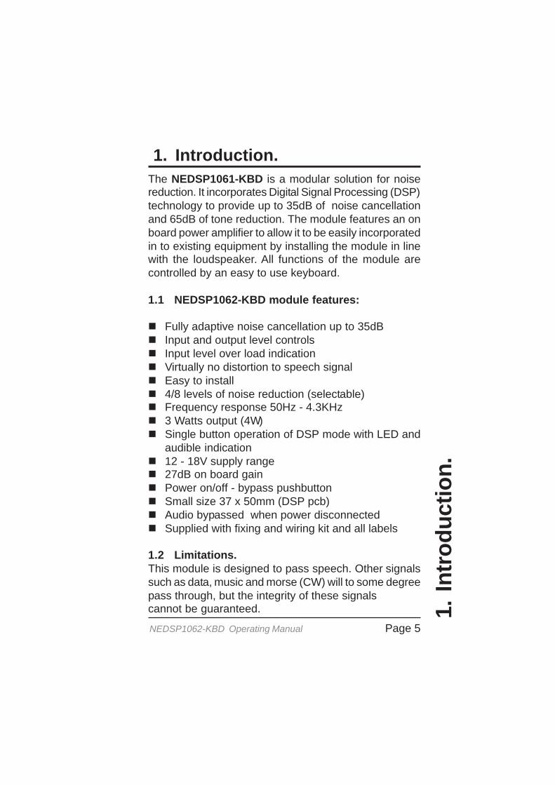
1. Introduction.The NEDSP1061-KBD is a modular solution for noisereduction. It incorporates Digital Signal Processing (DSP)technology to provide up to 35dB of noise cancellationand 65dB of tone reduction. The module features an onboard power amplifier to allow it to be easily incorporatedin to existing equipment by installing the module in linewith the loudspeaker. All functions of the module arecontrolled by an easy to use keyboard.
1.1 NEDSP1062-KBD module features:
Fully adaptive noise cancellation up to 35dBInput and output level controlsInput level over load indicationVirtually no distortion to speech signalEasy to install4/8 levels of noise reduction (selectable)Frequency response 50Hz - 4.3KHz3 Watts output (4W)Single button operation of DSP mode with LED andaudible indication12 - 18V supply range27dB on board gainPower on/off - bypass pushbuttonSmall size 37 x 50mm (DSP pcb)Audio bypassed when power disconnectedSupplied with fixing and wiring kit and all labels
1.2 Limitations.This module is designed to pass speech. Other signalssuch as data, music and morse (CW) will to some degreepass through, but the integrity of these signalscannot be guaranteed. 1.
Intr
od
uct
ion
.
Page 6 NEDSP1062-KBD Operating Manual
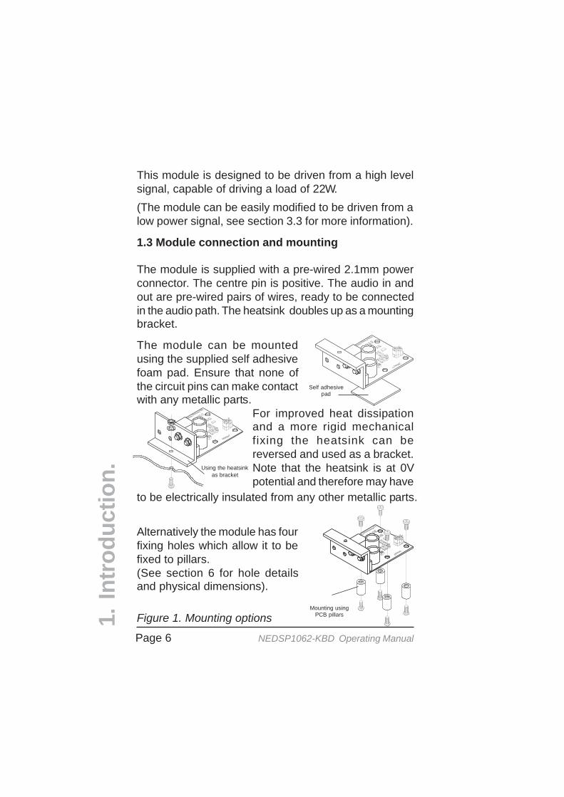
Figure 1. Mounting options
1.3 Module connection and mounting
The module is supplied with a pre-wired 2.1mm powerconnector. The centre pin is positive. The audio in andout are pre-wired pairs of wires, ready to be connectedin the audio path. The heatsink doubles up as a mountingbracket.
This module is designed to be driven from a high levelsignal, capable of driving a load of 22W.(The module can be easily modified to be driven from alow power signal, see section 3.3 for more information).
The module can be mountedusing the supplied self adhesivefoam pad. Ensure that none ofthe circuit pins can make contactwith any metallic parts.
For improved heat dissipationand a more rigid mechanicalfixing the heatsink can bereversed and used as a bracket.Note that the heatsink is at 0Vpotential and therefore may have
to be electrically insulated from any other metallic parts.
Alternatively the module has fourfixing holes which allow it to befixed to pillars.(See section 6 for hole detailsand physical dimensions).
1.In
tro
du
ctio
n. Using the heatsink
as bracket
Self adhesivepad
Mounting usingPCB pillars
Page 7NEDSP1062-KBD Operating Manual
1.In
tro
du
ctio
n.
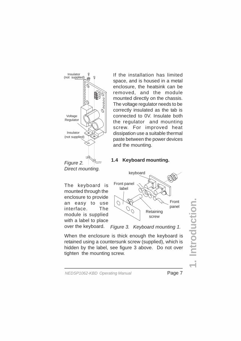
If the installation has limitedspace, and is housed in a metalenclosure, the heatsink can beremoved, and the modulemounted directly on the chassis.The voltage regulator needs to becorrectly insulated as the tab isconnected to 0V. Insulate boththe regulator and mountingscrew. For improved heatdissipation use a suitable thermalpaste between the power devicesand the mounting.
Figure 2.Direct mounting.
Figure 3. Keyboard mounting 1.
The keyboard ismounted through theenclosure to providean easy to useinterface. Themodule is suppliedwith a label to placeover the keyboard.
When the enclosure is thick enough the keyboard isretained using a countersunk screw (supplied), which ishidden by the label, see figure 3 above. Do not overtighten the mounting screw.
keyboard
Front panellabel
Retainingscrew
Frontpanel
Insulator
Insulator
VoltageRegulator
1.4 Keyboard mounting.
(not supplied)
(not supplied)
Page 8 NEDSP1062-KBD Operating Manual
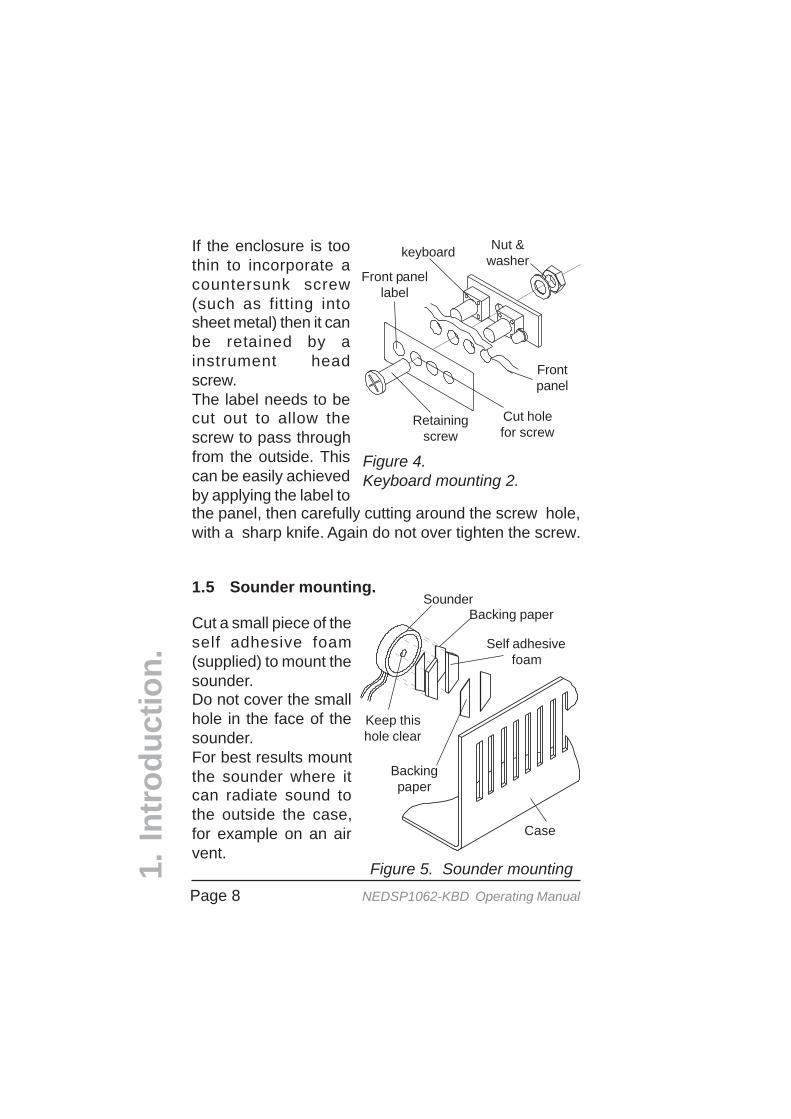
Figure 4.Keyboard mounting 2.
If the enclosure is toothin to incorporate acountersunk screw(such as fitting intosheet metal) then it canbe retained by ainstrument headscrew.The label needs to becut out to allow thescrew to pass throughfrom the outside. Thiscan be easily achievedby applying the label tothe panel, then carefully cutting around the screw hole,with a sharp knife. Again do not over tighten the screw.
Nut &washer
Front panellabel
keyboard
Retainingscrew
Frontpanel
1.5 Sounder mounting.
Cut a small piece of theself adhesive foam(supplied) to mount thesounder.Do not cover the smallhole in the face of thesounder.For best results mountthe sounder where itcan radiate sound tothe outside the case,for example on an airvent.
Figure 5. Sounder mounting
SounderBacking paper
Backingpaper
Self adhesivefoam
Case
Keep thishole clear
Cut holefor screw
1.In
tro
du
ctio
n.
Page 9NEDSP1062-KBD Operating Manual
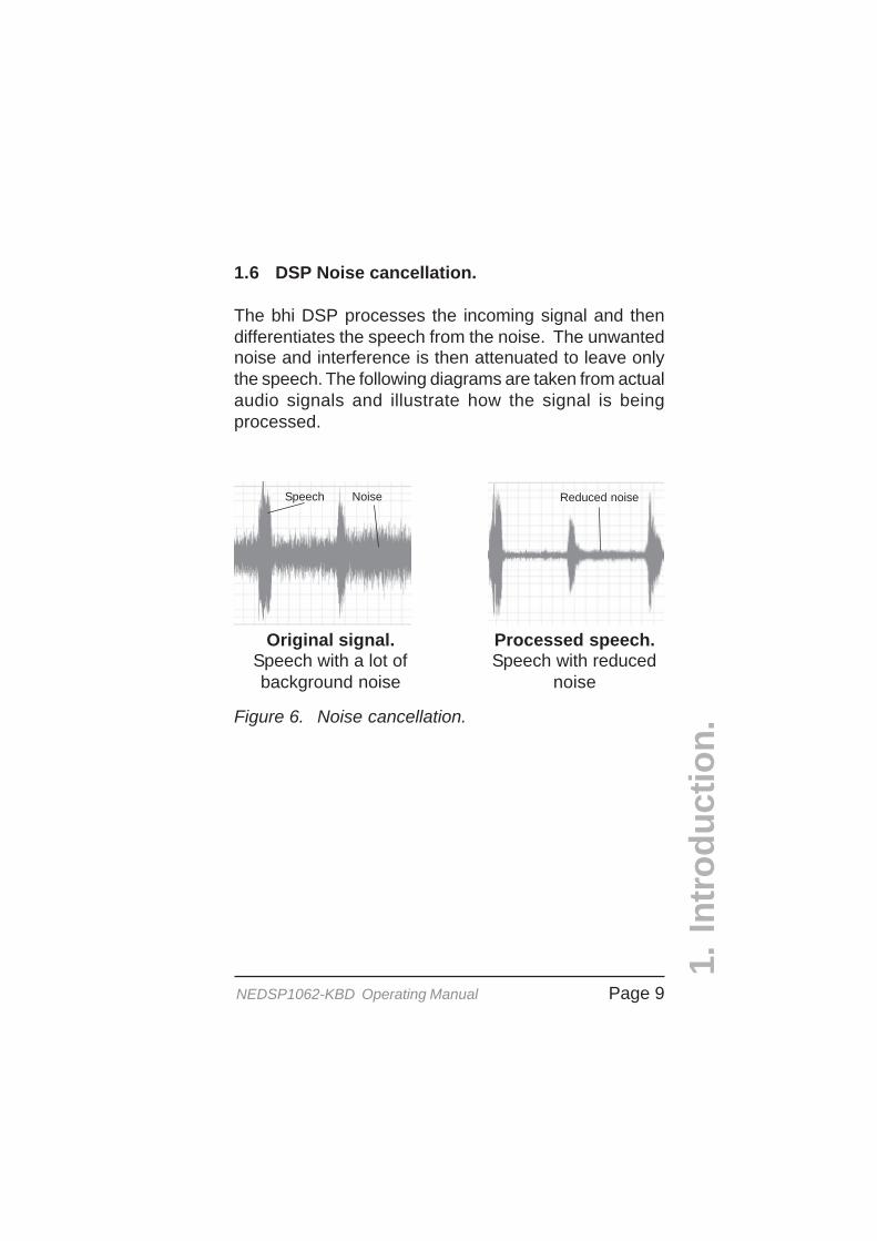
1.6 DSP Noise cancellation.
The bhi DSP processes the incoming signal and thendifferentiates the speech from the noise. The unwantednoise and interference is then attenuated to leave onlythe speech. The following diagrams are taken from actualaudio signals and illustrate how the signal is beingprocessed.
Figure 6. Noise cancellation.
Original signal.Speech with a lot ofbackground noise
Processed speech.Speech with reduced
noise
Speech Noise Reduced noise
1.In
tro
du
ctio
n.

Page 10 NEDSP1062-KBD Operating Manual
2. Module description.
Figure 7. NEDSP1062-KBD block diagram
1
3
8
Polarityprotection
Internalpull up
resistors
Input levelset
In 9
overloaddetect
Digital to analogueconversion
Output levelset
Pow er Amp
BCD DSP level select
Xtal
Clock generator
DSP core
5V5VRegulator
Latch
12V regulator
3.3V regulator
3.3V 12VRelayDrive
Relay 1
ON 14
Analogue to Digital conversion
70V
10
12
6
Power supplysection
PCBConnections
13
5
J3
InputLoad
resistor
Agnd
Agnd
Vin
NC
NO
NO
NCDSP
3V3 0V
PCB
microcontroller 4Keyboardinterface
8
N/C
N/C
Relay 1 Out
11
2.1 Block diagram.
2.M
od
ule
des
crip
tion
.

Page 11NEDSP1062-KBD Operating Manual
2.2 Module Layout.
The following diagram shows the layout of theNEDSP1062-KBD module.
Pin No. Name Description Notes
4 N/C Do not connect Not used
5 Vin Supply voltage 12 - 18VDC power in
6 N/C Do not connect Not used
7 0V 0V connection 0V power connections
9 In Audio input Audio signal in to be processed
10 Out Audio output Procesed audio signal out
11 Agnd 0V for input audio signal Analogue ground for audio in
12 Agnd 0V for output audio signal Analogue ground for audio out
Table 1. NEDSP1062 connection functions 2.M
od
ule
des
crip
tio
n.
Figure 8. NEDSP1062-KBD connections and controls
Inputlevel set
(P2)
Outputlevel set (P1)
Input overloadindicator LED
Mountingholes
Audiobypassrelay
The following table gives a description of the pin functions.
Note:Wiring obmitted for clarity
Soundervolume (P3)
2.3 Pin functions.
Page 12 NEDSP1062-KBD Operating Manual
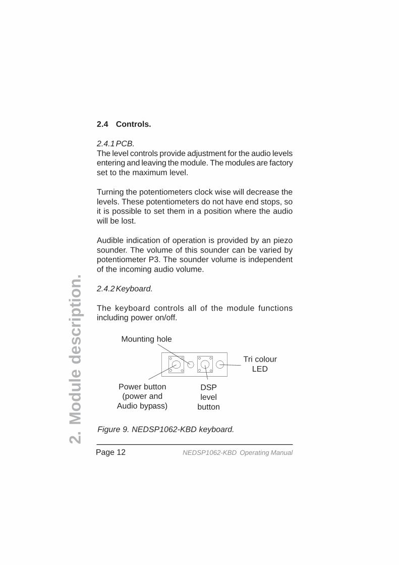
2.4 Controls.
2.4.1PCB.The level controls provide adjustment for the audio levelsentering and leaving the module. The modules are factoryset to the maximum level.
Turning the potentiometers clock wise will decrease thelevels. These potentiometers do not have end stops, soit is possible to set them in a position where the audiowill be lost.
Audible indication of operation is provided by an piezosounder. The volume of this sounder can be varied bypotentiometer P3. The sounder volume is independentof the incoming audio volume.
2.4.2Keyboard.
The keyboard controls all of the module functionsincluding power on/off.
2.M
od
ule
des
crip
tion
.
Figure 9. NEDSP1062-KBD keyboard.
Power button(power and
Audio bypass)
DSPlevel
button
Tri colourLED
Mounting hole

Page 13NEDSP1062-KBD Operating Manual
2.5 Electrical characteristics.
Symbol Parameter Test Conditions Min. Typ. Max. Units
Vs Supply voltage 12 16 18 V
Iqs Quiescent currentVs = 12VVs = 16VVs = 18V
4.66.87.1
mA
IqonQuiescent current DSP onno load no signal
Vs = 12VVs = 16VVs = 18V
143160161
mA
ELECTRICAL CHARACTERISTICS(Vs=16V, Tamb= 25iiiiiC unless otherwise stated)
DC CHARACTERISTICS
AC CHARACTERISTICSSymbol Parameter Test Conditions Min. Typ. Max. Units
Po Output power
d = 10%f = 1KHz
RL = 8WRL = 4W
12V
1.161.7
16V 18V
2.063.17
Vs
WW
Vi
Input sensitivty4W load
f = 1KHzPO = 0.5WPO = 1.0WPO = 2.0W
6090
130
mV
ViInput sensitivty8W load
f = 1KHzPO = 0.5WPO = 1.0WPO = 2.0W
81117180
mV
B Frequency response(-3dB)
Po = 1WRL = 8W
50 4300 Hz
d Distortionf = 1KHzPO = 0.2 - 2.4W R L= 8WPO = 0.2 - 2.4W R L= 4W
0.80.8
%
Ri Input resistance 21 22 23 W
Gv Voltage gain f = 1KHz 27 dB
n Efficiencyf = 1KHzPO = 3W R L = 4WPO = 2W R L = 8W
3338
%
ANALOGUE CHARACTERISTICSSymbol Parameter Test Conditions Min Typ Max. Units
Td System delay 26 mS
2.M
od
ule
des
crip
tion
.
Table 2. Electrical characteristics 1

Page 14 NEDSP1062-KBD Operating Manual
-20
-15
-10
-5
0
5
0 1000 2000 3000 4000 5000 6000
Figure 10. Frequency response
Frequency (Hz)
Out
put (
dB)
0
2
4
6
8
10
12
0 0.5 1 1.5 2 2.5 3 3.5
Figure 11. Distortion vs. Output power
Dis
torti
on
Output power (W)
VS = 16Vf = 1KHz RL = 8W
RL = 4W
2.M
od
ule
des
crip
tion
.
RL = 8W
VS = 16V
P = 1W
-3dB
Page 15NEDSP1062-KBD Operating Manual
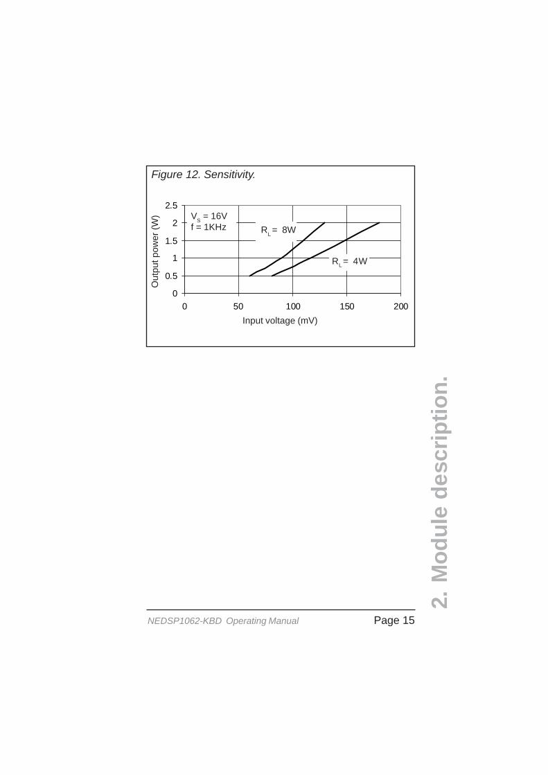
Figure 12. Sensitivity.
0
0.5
1
1.5
2
2.5
0 50 100 150 200Input voltage (mV)
Out
put p
ower
(W)
RL = 8W
RL = 4W
VS = 16Vf = 1KHz
2.M
od
ule
des
crip
tion
.

Page 16 NEDSP1062-KBD Operating Manual
Figure 13. Basic connection diagram
3.1 Installation overview.
The NEDSP1062-KBD module is inserted into the pathof noisy audio. The input and output level controls allowthe module to be fine tuned to suit most applications.
3. Installation
Audio in
Power amp
+
-
Break Circuithere
Audio Out(Loudspeaker)
The input to the module is loaded at 22W to provide adummy load to the preceding circuit. This can be removedif required, such as using the module in applicationswhere the audio source is provided by a low level, lowpower signal source. More information on this can befound in section 3.3 in this operating manual.
If Vin is less than approx. 13.8V ensure the power supplyis well decoupled otherwise the power supply rejectionratio will deteriorate. Best results are obtained in therange of 13.8V - 16Vdc.
Audio in
NEDSP1062Power amp
+
-
IN
Agnd Agnd
OUT
Keyboard
Power
10
12
9
11 Black
Piezosounder
BlueRed
Black
3.In
stal
lati
on
.

Page 17NEDSP1062-KBD Operating Manual
3.2 Module setup.
3.In
stal
lati
on
.3.2.2 Suggested set up procedure:
Basic setup procedure.Connect input source and output device.Ensure the NEDSP1062-KBD is switched off.Set the audio source to a typical audio level.Switch on the NEDSP1062-KBD.Adjust the input control (P2) until the overload LEDilluminates. Reduce the level by approx. 1/4 turn.Adjust the output level to the desired level.Hold down the DSP button and adjust the volume
of the sounder to suit using P3.
To obtain the best results from the noise reduction themodule should be set up to give optimum performance.The input sensitivity control has a range of 0.70mW -3W to provide 2W (W)output.
Under certain conditions, RF breakthrough cansometimes occur. To minimize this, the input level (P2)may need to be reduced or go to the FAQ page on thebhi website and download the FAQ on RF breakthrough.
Under certain conditions the DSP can create a smallamount of noise, normally when the unit has no signalapplied. You should not be able to hear this noise whena signal is applied.
Both the input and output levels are adjustable on themodule. This allows easy integration into the target system.
3.2.1 Overview.
Page 18 NEDSP1062-KBD Operating Manual
The NEDSP1062-KBD requires a signal of 125mV rmsor greater for optimum performance. Signals lower thanthis may be used but the noise cancellation performancewill decrease, as the signal levels drops. If the unit isused with low level signals such as microphones, thesignal will need amplifying before applying it to theNEDSP1062-KBD.Due to the adaptive nature of the noise cancellation asmall delay may be heard when the audio signalchanges. For optimum performance provide the modulewith a constant signal where possible.
When switching on the unit a thump may be heard in theloudspeaker.3.
Inst
alla
tio
n.
Figure 14. Input circuit -module powered down
22W
OUT
12Agnd
Agnd
9
10
V
AudioInput
NEDSP1062
R6
IN
Load
11
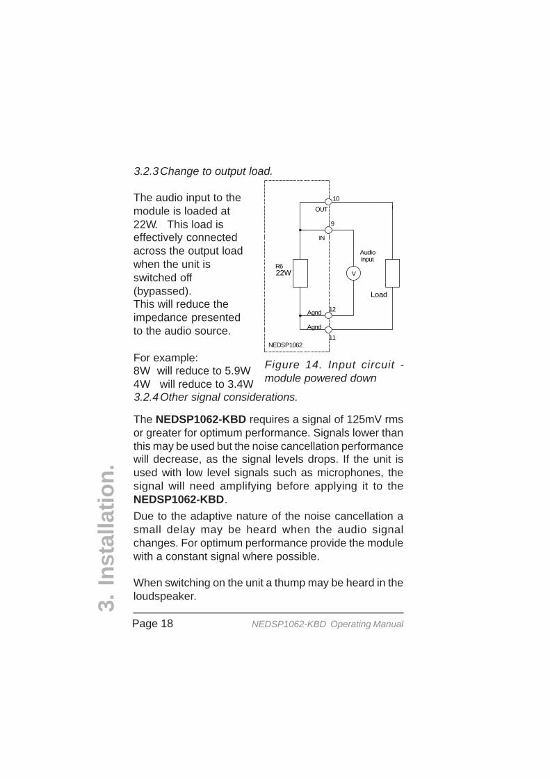
The audio input to themodule is loaded at22W. This load iseffectively connectedacross the output loadwhen the unit isswitched off(bypassed).This will reduce theimpedance presentedto the audio source.
For example:8W will reduce to 5.9W4W will reduce to 3.4W
3.2.3Change to output load.
3.2.4Other signal considerations.

Page 19NEDSP1062-KBD Operating Manual
Figure 16. Circuit modification for low power signal drive.
3.3 Driving from a low signal source.
The input to the module has a low impedance. This is toprovide correct loading to any power circuits driving it. Ifthe module needs to be driven from a low power signalthen it must be modified in the following manner.
Cut theleg on this
resistor
3.In
stal
lati
on
.
22W
OUT
12Agnd
Agnd
9
10
LoadV
AudioInput
NEDSP1062
R6
IN
11
Circuitmodification
Figure 15. Physical modification for low power signaldrive.
Note:Wiring
omitted forclarity.

Page 20 NEDSP1062-KBD Operating Manual
4. Operation.
4.O
per
atio
n.
4.1 Keyboard.The keyboard has 2 buttons and a tricolour LED.
4.1.1Power button.The power button switched the module on and off. Whenthe module is off, the audio bypasses the module, sothe circuit will behave as if the module isn’t present.Switching the power on routes the audio through themodule.
Note: If the power is on and the DSP is switched off, theaudio still passes through the DSP - but without any signalprocessing.A single press on the button switches on, and a singlepress will switch off. Also with the power connected andthe module switched off the circuit will still draw 6mA.
4.1.2DSP level button.This button is used to set the following:• DSP on/off• DSP level• 4 or 8 levels of noise cancellation• Demonstration modes
Figure 17. NEDSP1062-KBD keyboard.
Power button(power and
Audio bypass)
DSPlevel
button
Tri colourLED

Page 21NEDSP1062-KBD Operating Manual
Power up
DSP buttonpressed
2 tone sound
DSP buttonpressed
2 tone sound
2 tone sound
Demonstration2
Demonstration1
No
Yes
No
Yes
No
Yes
DSP buttonpressed
DSP buttonpressed
2 tone sound
DSP buttonpressed
Change 4 or 8 lev els
Normal operation
No
Yes beep numberof DSP lev els
Yes No DSP button
pressed
Yes
No
4.O
per
atio
n.
4.2 Set up.The following flow chart shows the functions of the DSPbutton.
Releasing the DSP buttonat this point the modulegoes in to demonstrationmode 1
Keep the button downuntil the desired levelhas been reached, thenrelease the button. Themodule will continouslyscroll through 4 and 8levels until the button isreleased.
Figure 18. 4/8 level setting.
Holding down the DSPbutton when switching oncauses the module to enterthe set up mode.
This is indicated by a 2tone beep.
Releasing the DSP buttonat this point the modulegoes in to demonstrationmode 2
Page 22 NEDSP1062-KBD Operating Manual
4.O
per
atio
n.
To listen to the demonstration modes, or change thenumber of DSP levels it is necessary to put the moduleinto the set up mode.
To do this, ensure the module is Off. Press and hold theDSP level button. Turn on the module and a 2 tonebeep will be heard indicating that the module is in theset up mode.
Releasing the button after the first 2 tone beep will enterdemonstration mode 1.
Releasing after the second 2 tone beep will enterdemonstration mode 2.
Keeping the button depressed with change the numberof levels available. 4 beeps will indicate 4 level modeand 8 beeps 8 levels. Release the button when thedesired level is reached.
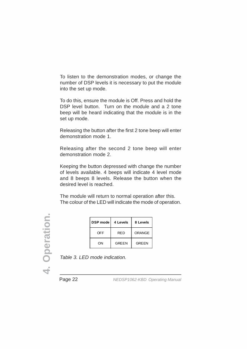
The module will return to normal operation after this.The colour of the LED will indicate the mode of operation.
DSP mode 4 Levels 8 Levels
OFF RED ORANGE
ON GREEN GREEN
Table 3. LED mode indication.
Page 23NEDSP1062-KBD Operating Manual
4.O
per
atio
n.
Start
Noise cancellationOn
Wait 1.5 Seconds
Noise cancellation of f
HighestLev el?
Normal operation
No
Yes
Increase DSPnoise cancellation
lev el
Start
Noise cancellation of f
Noise cancellationOn
Wait 3 Seconds
No
Yes
DSP buttonpressed?
2 tone beep
Normal operation
Wait 3 Seconds
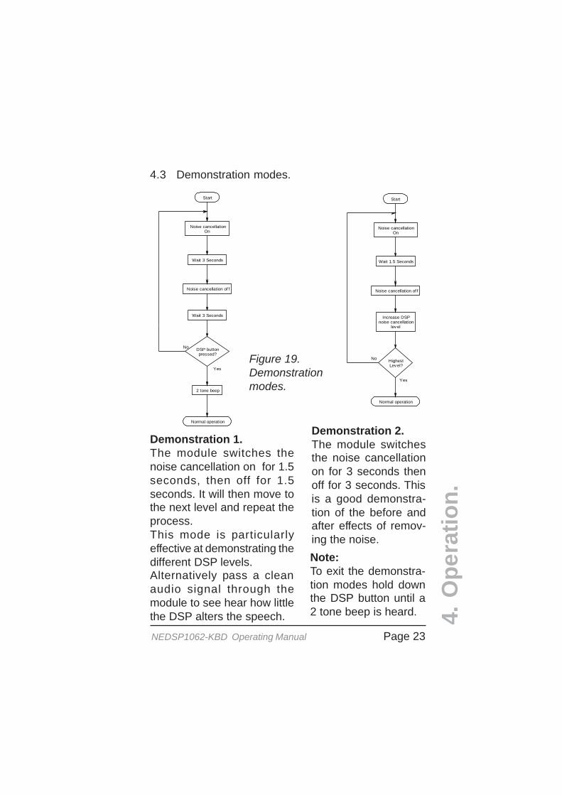
Demonstration 2.The module switchesthe noise cancellationon for 3 seconds thenoff for 3 seconds. Thisis a good demonstra-tion of the before andafter effects of remov-ing the noise.
Demonstration 1.The module switches thenoise cancellation on for 1.5seconds, then off for 1.5seconds. It will then move tothe next level and repeat theprocess.This mode is particularlyeffective at demonstrating thedifferent DSP levels.Alternatively pass a cleanaudio signal through themodule to see hear how littlethe DSP alters the speech.
Note:To exit the demonstra-tion modes hold downthe DSP button until a2 tone beep is heard.
Figure 19.Demonstrationmodes.
4.3 Demonstration modes.
Page 24 NEDSP1062-KBD Operating Manual
4.O
per
atio
n.
4.4 Noise reduction levels.
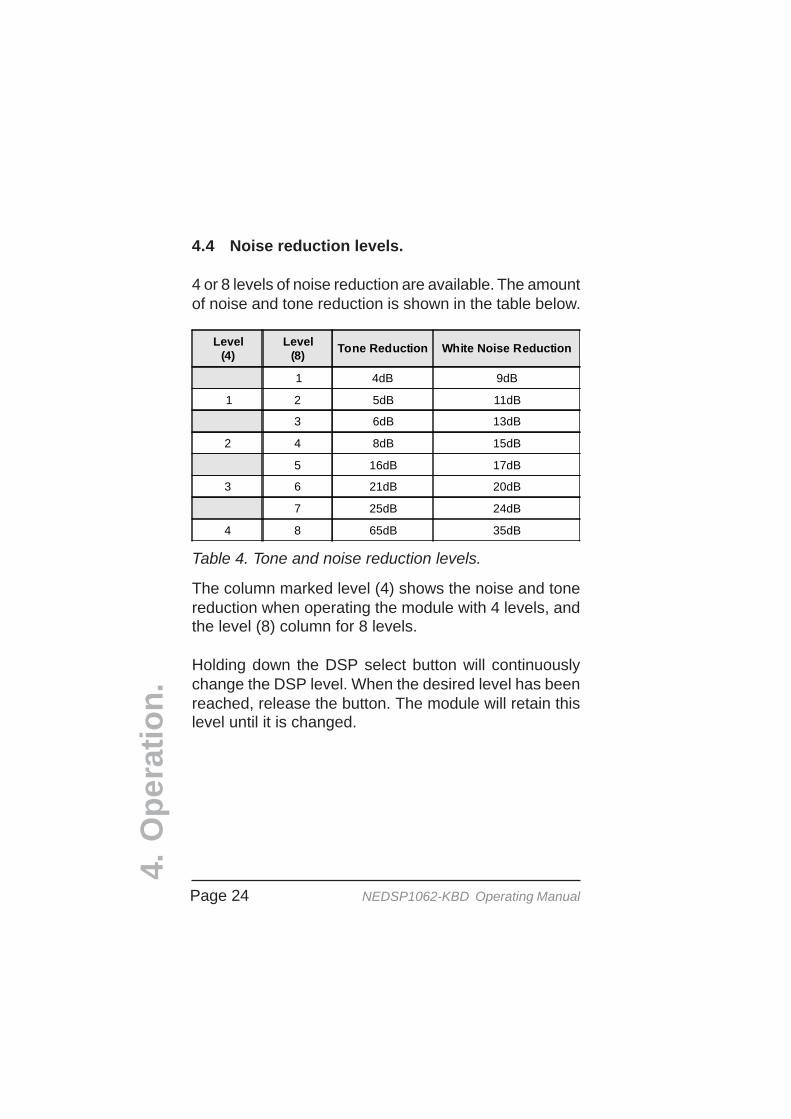
4 or 8 levels of noise reduction are available. The amountof noise and tone reduction is shown in the table below.
Level(4)
Level(8) Tone Reduction White Noise Reduction
1 4dB 9dB
1 2 5dB 11dB
3 6dB 13dB
2 4 8dB 15dB
5 16dB 17dB
3 6 21dB 20dB
7 25dB 24dB
4 8 65dB 35dB
Table 4. Tone and noise reduction levels.
The column marked level (4) shows the noise and tonereduction when operating the module with 4 levels, andthe level (8) column for 8 levels.
Holding down the DSP select button will continuouslychange the DSP level. When the desired level has beenreached, release the button. The module will retain thislevel until it is changed.
Page 25NEDSP1062-KBD Operating Manual
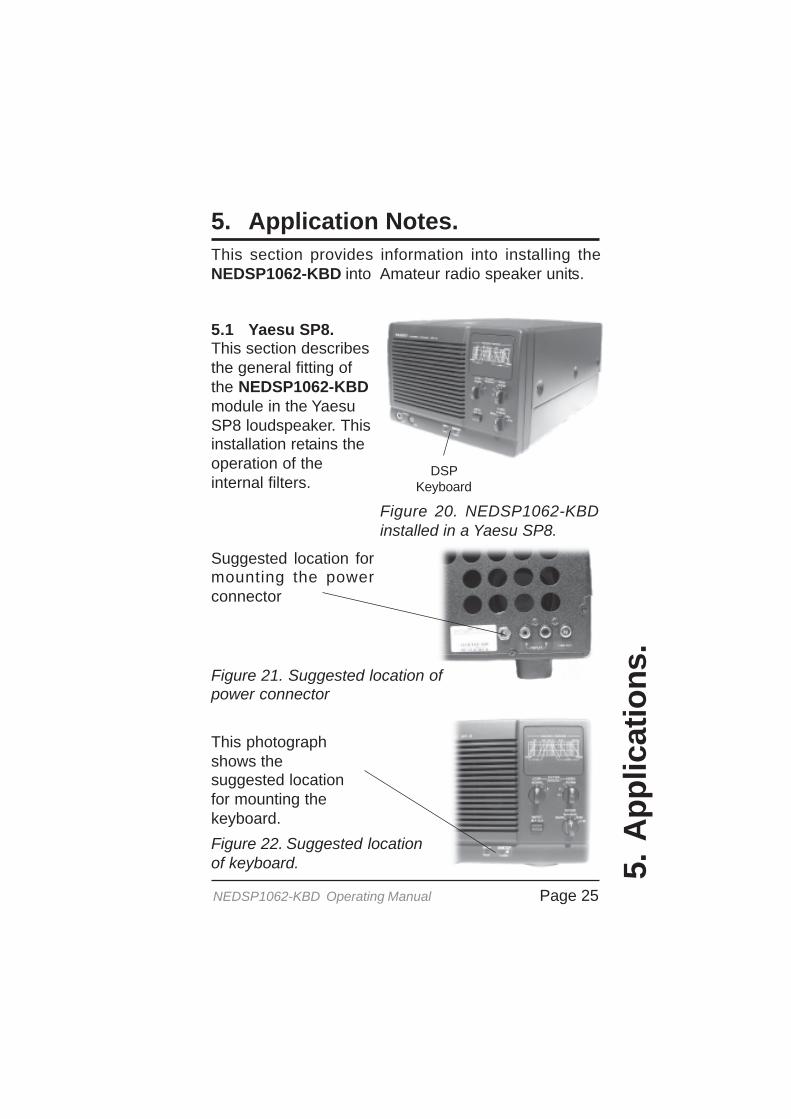
5. Application Notes.
5.A
pp
licat
ion
s.
This section provides information into installing theNEDSP1062-KBD into Amateur radio speaker units.
Figure 20. NEDSP1062-KBDinstalled in a Yaesu SP8.
5.1 Yaesu SP8.This section describesthe general fitting ofthe NEDSP1062-KBDmodule in the YaesuSP8 loudspeaker. Thisinstallation retains theoperation of theinternal filters.
DSPKeyboard
Figure 21. Suggested location ofpower connector
Figure 22. Suggested locationof keyboard.
This photographshows thesuggested locationfor mounting thekeyboard.
Suggested location formounting the powerconnector
Page 26 NEDSP1062-KBD Operating Manual
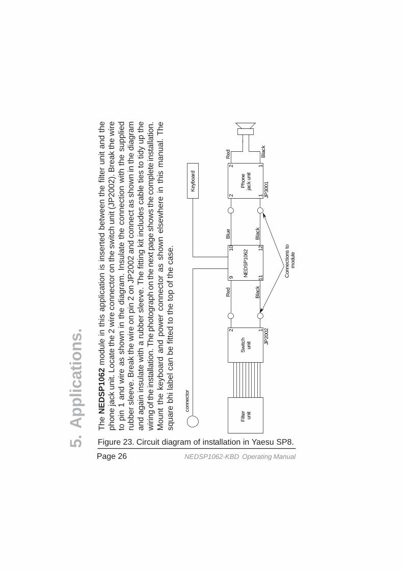
Figure 23. Circuit diagram of installation in Yaesu SP8.5.A
pp
licat
ion
s.
NED
SP10
62Fi
lter
unit
Switc
hun
itPh
one
jack
uni
t
12
Blac
k
Red
122 1
Keyb
oard
conn
ecto
r
Blac
kBl
ack
9 111210
Con
nect
ions
to
mod
ule
JP20
02JP
3001
Red
Blue
The
NED
SP10
62 m
odul
e in
this
app
licat
ion
is in
serte
d be
twee
n th
e fil
ter u
nit a
nd th
eph
one
jack
uni
t. Lo
cate
the
2 w
ire c
onne
ctor
on
the
switc
h un
it (J
P20
02).
Bre
ak th
e w
ireto
pin
1 a
nd w
ire a
s sh
own
in th
e di
agra
m. I
nsul
ate
the
conn
ectio
n w
ith th
e su
pplie
dru
bber
sle
eve.
Bre
ak th
e w
ire o
n pi
n 2
on J
P20
02 a
nd c
onne
ct a
s sh
own
in th
e di
agra
man
d ag
ain
insu
late
with
a ru
bber
sle
eve.
The
fitti
ng k
it in
clud
es c
able
ties
to ti
dy u
p th
ew
iring
of t
he in
stal
latio
n. T
he p
hoto
grap
h on
the
next
pag
e sh
ows
the
com
plet
e in
stal
latio
n.M
ount
the
key
boar
d an
d po
wer
con
nect
or a
s sh
own
else
whe
re in
thi
s m
anua
l. Th
esq
uare
bhi
labe
l can
be
fitte
d to
the
top
of th
e ca
se.

Page 27NEDSP1062-KBD Operating Manual
Figure 24. Complete installation in the Yaesu SP8.
DSPmodule
InputPCB
Powerconnector
5.A
pp
licat
ion
s.
Page 28 NEDSP1062-KBD Operating Manual
5.A
pp
licat
ion
s.
DSPKeyboard
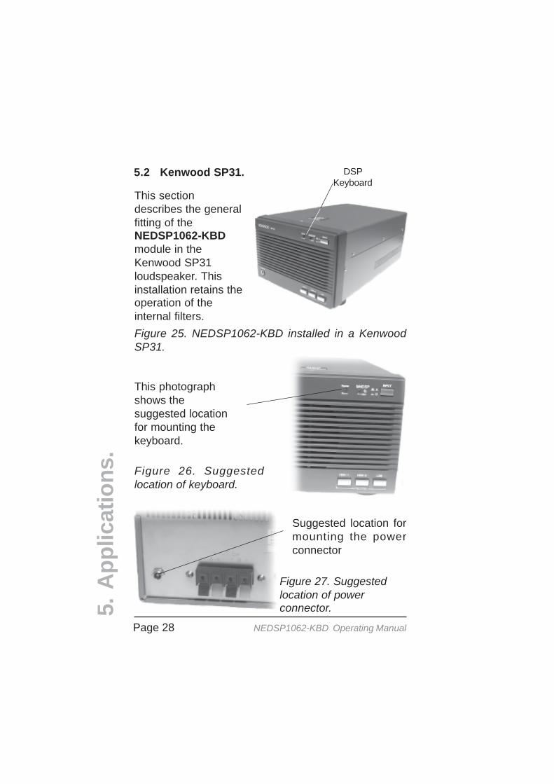
5.2 Kenwood SP31.
Figure 25. NEDSP1062-KBD installed in a KenwoodSP31.
This sectiondescribes the generalfitting of theNEDSP1062-KBDmodule in theKenwood SP31loudspeaker. Thisinstallation retains theoperation of theinternal filters.
Figure 26. Suggestedlocation of keyboard.
Figure 27. Suggestedlocation of powerconnector.
Suggested location formounting the powerconnector
This photographshows thesuggested locationfor mounting thekeyboard.

Page 29NEDSP1062-KBD Operating Manual
5.A
pp
licat
ion
s.
NE
DS
P10
62
Line
out
Inpu
tS
elec
tor
Inpu
tP
CB
Pow
er
Red
Whi
te
Bla
ck
Bro
wn
0V
Hea
dpho
nes
Filte
rB
lue
Bla
ck0V
Line
out
Key
boar
d
Yel
low
Yel
low
43
125
12
3
12
21
43
Bla
ckB
lack
9 11
10 12
Con
nect
ions
to
mod
ule
Bla
ck
Red
Blu
eR
ed
Figure 28. Circuit diagram of installation in KenwoodSP31.
The
mod
ule
is in
serte
d in
to th
e ci
rcui
t bef
ore
the
filte
r PC
B. I
dent
ify th
e ye
llow
wire
conn
ectin
g th
e in
put s
elec
tor s
witc
h to
the
filte
r boa
rd. B
reak
the
wire
and
con
nect
the
NED
SP10
62-K
BD
as
show
n be
low
. Ins
ulat
e th
e w
ires
with
the
supp
lied
rubb
ersl
eeve
s. Id
entif
y th
e bl
ack
wire
from
the
inpu
t PC
B a
nd c
onne
ct a
s sh
own
belo
w,ag
ain
insu
latin
g th
e co
nnec
tions
. Th
e fit
ting
kit
incl
udes
cab
le t
ies
to t
idy
up t
hew
iring
of
the
inst
alla
tion.
The
pho
togr
aph
on t
he n
ext
page
sho
ws
the
com
plet
ein
stal
latio
n. M
ount
the
keyb
oard
and
pow
er c
onne
ctor
as
show
n el
sew
here
in th
ism
anua
l. Th
e sq
uare
bhi
labe
l can
be
fitte
d to
the
top
of th
e ca
se.
Page 30 NEDSP1062-KBD Operating Manual
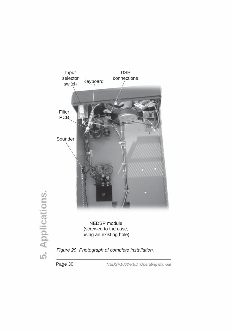
Figure 29. Photograph of complete installation.
Sounder
NEDSP module(screwed to the case,using an existing hole)
Inputselectorswitch
FilterPCB
DSPconnections
Keyboard
5.A
pp
licat
ion
s.
Page 31NEDSP1062-KBD Operating Manual
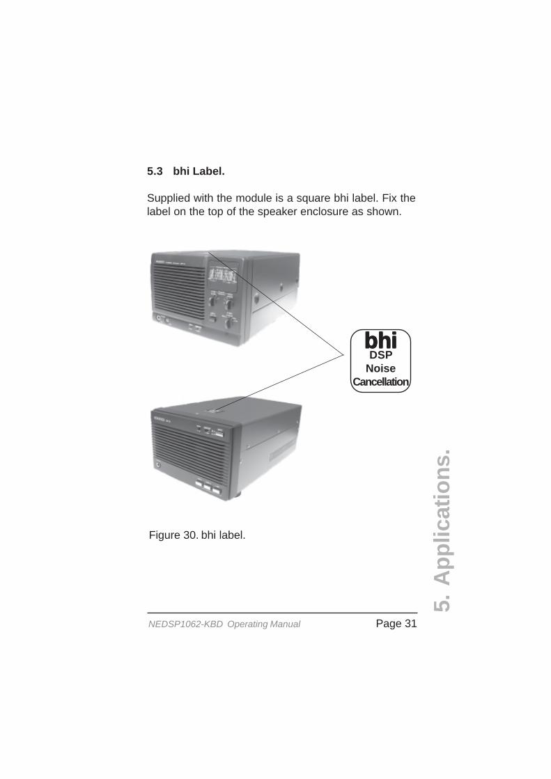
Figure 30. bhi label.
5.A
pp
licat
ion
s.
5.3 bhi Label.
Supplied with the module is a square bhi label. Fix thelabel on the top of the speaker enclosure as shown.
bhibhibhibhibhiDSP
NoiseCancellation

Page 32 NEDSP1062-KBD Operating Manual
23.4
2.97
30.3
34.3
36.5
49.6
2.97 Pin 1
3mm dia
6.P
hys
ical
dim
ensi
on
s.
6. Physical Dimensions
Figure 31. Mounting hole positions.
Top
6.1 Physical dimensions.The following diagrams detail the physical dimensionsof the module. All dimensions are in mm.

Page 33NEDSP1062-KBD Operating Manual
6.P
hys
ical
dim
ensi
on
s.Components fitted torear of PCB
Figure 32. Overall dimensions.
Figure 33. Hole dimensions of power devices - for directmounting applications.
16.1
5.3
17.9
16.4
Viewed fromthe end ofthe module
34.2
64.4
5.8
Page 34 NEDSP1062-KBD Operating Manual
6.P
hys
ical
dim
ensi
on
s.
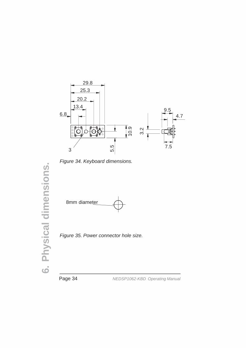
Figure 34. Keyboard dimensions.
Figure 35. Power connector hole size.
29.825.3
20.213.4
6.89.5
4.7
7.53.
2
10.9
5.5
3
8mm diameter

Page 35NEDSP1062-KBD Operating Manual
6.P
hys
ical
dim
ensi
on
s.
6.2 Template.
The following drawing shows the sizes and positions ofholes for the keyboard.
Figure 36. Keyboard drilling detail .
Not to scaleall dimensions in mm
29.818.5
13.4
6.7
6.7
10.9 5.
54mm
4mm 4mm
3mm CSKto 5mm

Page 36 NEDSP1062-KBD Operating Manual
<This page is intentionaly blank>

Page 37NEDSP1062-KBD Operating Manual
Star
t
Incr
ease
inpu
tle
vel
Ove
r loa
d LE
Dillu
min
ates
? N
o
Yes
Redu
ce in
put
so L
ED g
oes
out
Incr
ease
out
put
leve
l P1
Suff
icie
ntou
tput
vol
ume?
Supp
ly v
olta
ge<1
3.8
Vdc
Inpu
t lev
elto
o lo
w
Incr
ease
supp
lyvo
ltage
Fini
sh Yes
Disc
onne
ctR6
(see
sec
tion
3.3)
Ove
r loa
d LE
Dillu
min
ates
?
Add
add
itiona
lam
plifi
catio
n
No
Yes
No
No
Yes
7.2
Insu
ffuci
ent o
utpu
tvo
lum
e 7. Troubleshooting
Inpu
tsi
gnal
Ove
rload
LE
D on
Redu
ce in
put
leve
l
Incr
ease
ou
tput
leve
lP1
App
lyau
dio
sign
al
Incr
ease
inpu
tsi
gnal
P2
No
Yes
No
Yes
Aud
io
out?
Fini
sh
Star
t
Yes
No
7.1
No
audi
o ou
t
7.Tr
ou
ble
sho
oti
ng
.

Page 38 NEDSP1062-KBD Operating Manual
8. Other bhi productsOther noise cancellation products from bhi. Visit www.bhi-ltd.co.ukfor more information.
DSP noise cancellation built into a compactspeaker unit. the unit provides an easy toinstall solution to noise reduction
Features:• Fully adaptive noise cancellation 9 -35dB• 8 user selectable noise cancellation levels• Mono earpiece socket• Input sensitivity control• Noise cancellation On/Off switch• LED indication of power and noise cancellation• 12-24VDC operation• On/Off audio bypass switch.• Greatly improved signal to noise ratio• Easy to install with adjustable mounting bracket• 2m audio lead• Optional extras avaiable.
8.1 NES10-2 MKII Noise Eliminating speaker.
Basic plug and go noise cancellingspeaker preset to 20dB of noisereduction.
Features:• Fully adaptive noise cancellation 20dB• 12-24VDC operation• Compact robust speaker unit.• Greatly improved signal to noise ratio• Easy to install with adjustable mounting bracket• 2m audio lead
8.2 NES5 Noise Eliminating speaker.
8.O
ther
bh
i pro
du
cts.
Page 39NEDSP1062-KBD Operating Manual
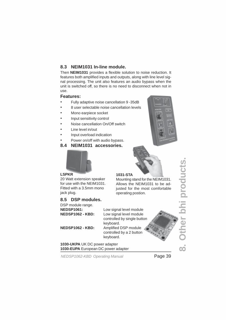
8.3 NEIM1031 In-line module.Then NEIM1031 provides a flexible solution to noise reduction. Itfeatures both amplified inputs and outputs, along with line level sig-nal processing. The unit also features an audio bypass when theunit is switched off, so there is no need to disconnect when not inuse.Features:• Fully adaptive noise cancellation 9 -35dB• 8 user selectable noise cancellation levels• Mono earpiece socket• Input sensitivity control• Noise cancellation On/Off switch• Line level in/out• Input overload indication• Power on/off with audio bypass.8.4 NEIM1031 accessories.
8.5 DSP modules.
LSPKR20 Watt extension speakerfor use with the NEIM1031.Fitted with a 3.5mm monojack plug.
1031-STAMounting stand for the NEIM1031.Allows the NEIM1031 to be ad-justed for the most comfortableoperating postion.
8.O
ther
bh
i pro
du
cts.
DSP module range.NEDSP1061: Low signal level moduleNEDSP1062 - KBD: Low signal level module
controlled by single buttonkeyboard.
NEDSP1062 - KBD: Amplified DSP modulecontrolled by a 2 buttonkeyboard.
1030-UKPA UK DC power adapter1030-EUPA European DC power adapter
Page 40 NEDSP1062-KBD Operating Manual
bhi LtdP.O. Box 318Burgess Hill
West SussexRH15 9NR
tel: +44 (0)845 2179926fax: +44 (0)845 2179936
bhibhibhibhibhi
DSP
Noi
se C
ance
llatio
n Pr
oduc
ts
DSP Noise Cancellation


