NDN Membrane Software
11
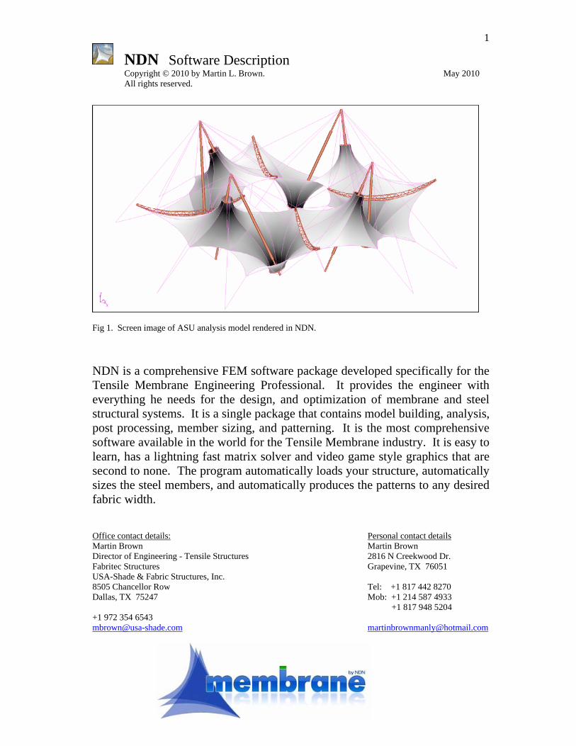
1 NDN Software Description Copyright © 2010 by Martin L. Brown. May 2010 All rights reserved. Fig 1. Screen image of ASU analysis model rendered in NDN. NDN is a comprehensive FEM software package developed specifically for the Tensile Membrane Engineering Professional. It provides the engineer with everything he needs for the design, and optimization of membrane and steel structural systems. It is a single package that contains model building, analysis, post processing, member sizing, and patterning. It is the most comprehensive software available in the world for the Tensile Membrane industry. It is easy to learn, has a lightning fast matrix solver and video game style graphics that are second to none. The program automatically loads your structure, automatically sizes the steel members, and automatically produces the patterns to any desired fabric width. Office contact details: Personal contact details Martin Brown Martin Brown Director of Engineering - Tensile Structures 2816 N Creekwood Dr. Fabritec Structures Grapevine, TX 76051 USA-Shade & Fabric Structures, Inc. 8505 Chancellor Row Tel: +1 817 442 8270 Dallas, TX 75247 Mob: +1 214 587 4933 +1 817 948 5204 +1 972 354 6543 [email protected] [email protected]
-
Upload
shaikh-muhammad-ateeq -
Category
Documents
-
view
700 -
download
76
description
NDN Membrane Software for the design of High Tensile membrane Structures
Transcript of NDN Membrane Software
1
NDN Software Description Copyright © 2010 by Martin L. Brown. May 2010 All rights reserved.
Fig 1. Screen image of ASU analysis model rendered in NDN. NDN is a comprehensive FEM software package developed specifically for the Tensile Membrane Engineering Professional. It provides the engineer with everything he needs for the design, and optimization of membrane and steel structural systems. It is a single package that contains model building, analysis, post processing, member sizing, and patterning. It is the most comprehensive software available in the world for the Tensile Membrane industry. It is easy to learn, has a lightning fast matrix solver and video game style graphics that are second to none. The program automatically loads your structure, automatically sizes the steel members, and automatically produces the patterns to any desired fabric width. Office contact details: Personal contact details Martin Brown Martin Brown Director of Engineering - Tensile Structures 2816 N Creekwood Dr. Fabritec Structures Grapevine, TX 76051 USA-Shade & Fabric Structures, Inc. 8505 Chancellor Row Tel: +1 817 442 8270 Dallas, TX 75247 Mob: +1 214 587 4933
+1 817 948 5204 +1 972 354 6543 [email protected] [email protected]
2
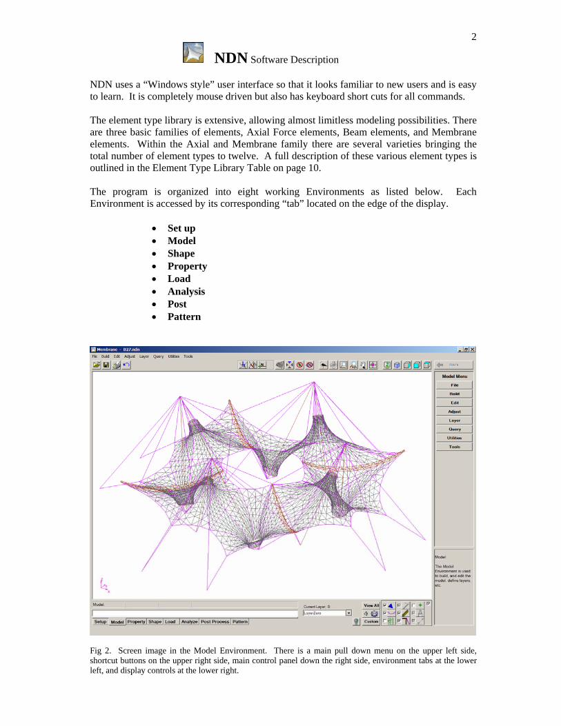
NDN Software Description NDN uses a “Windows style” user interface so that it looks familiar to new users and is easy to learn. It is completely mouse driven but also has keyboard short cuts for all commands. The element type library is extensive, allowing almost limitless modeling possibilities. There are three basic families of elements, Axial Force elements, Beam elements, and Membrane elements. Within the Axial and Membrane family there are several varieties bringing the total number of element types to twelve. A full description of these various element types is outlined in the Element Type Library Table on page 10. The program is organized into eight working Environments as listed below. Each Environment is accessed by its corresponding “tab” located on the edge of the display.
• Set up • Model • Shape • Property • Load • Analysis • Post • Pattern
Fig 2. Screen image in the Model Environment. There is a main pull down menu on the upper left side, shortcut buttons on the upper right side, main control panel down the right side, environment tabs at the lower left, and display controls at the lower right.
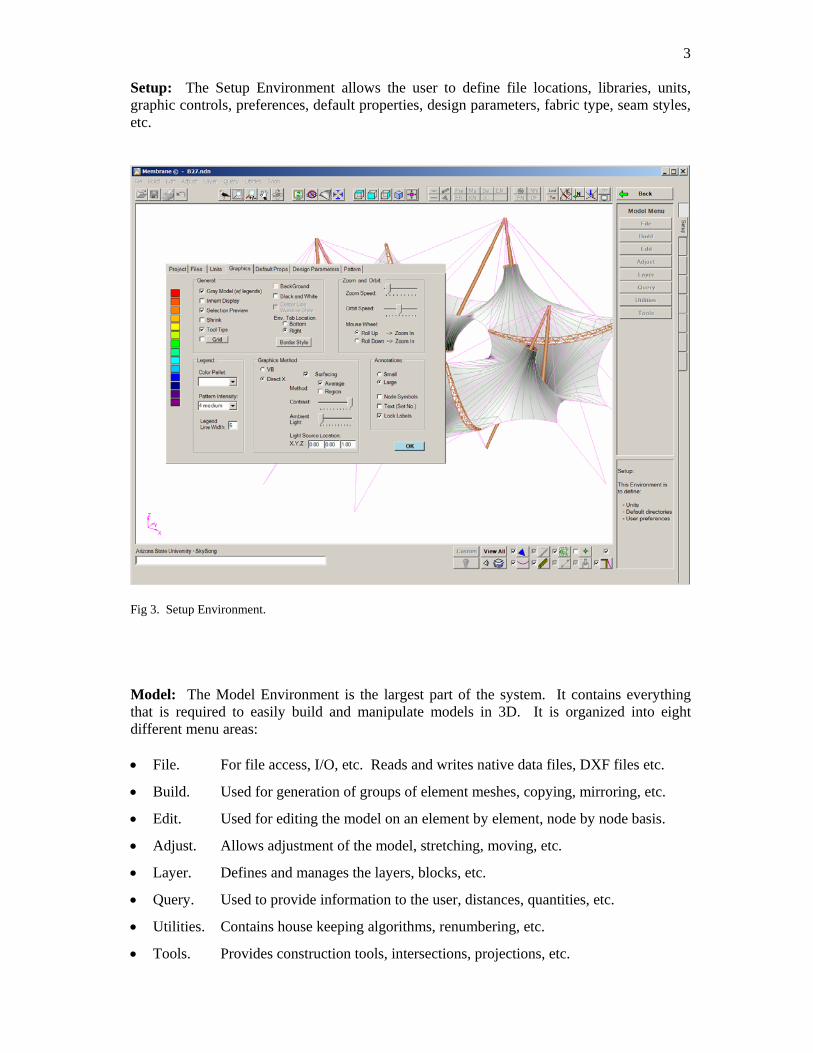
3 Setup: The Setup Environment allows the user to define file locations, libraries, units, graphic controls, preferences, default properties, design parameters, fabric type, seam styles, etc.
Fig 3. Setup Environment. Model: The Model Environment is the largest part of the system. It contains everything that is required to easily build and manipulate models in 3D. It is organized into eight different menu areas: • File. For file access, I/O, etc. Reads and writes native data files, DXF files etc.
• Build. Used for generation of groups of element meshes, copying, mirroring, etc.
• Edit. Used for editing the model on an element by element, node by node basis.
• Adjust. Allows adjustment of the model, stretching, moving, etc.
• Layer. Defines and manages the layers, blocks, etc.
• Query. Used to provide information to the user, distances, quantities, etc.
• Utilities. Contains house keeping algorithms, renumbering, etc.
• Tools. Provides construction tools, intersections, projections, etc.
4
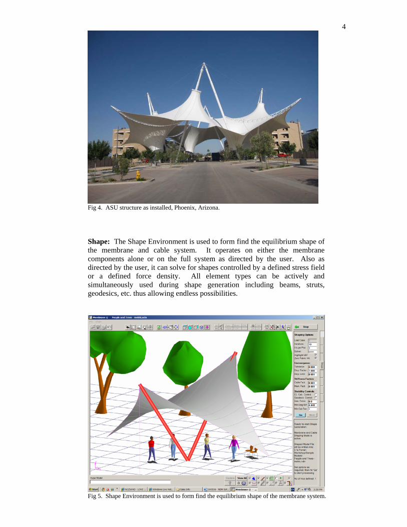
Fig 4. ASU structure as installed, Phoenix, Arizona.
Shape: The Shape Environment is used to form find the equilibrium shape of the membrane and cable system. It operates on either the membrane components alone or on the full system as directed by the user. Also as directed by the user, it can solve for shapes controlled by a defined stress field or a defined force density. All element types can be actively and simultaneously used during shape generation including beams, struts, geodesics, etc. thus allowing endless possibilities.
Fig 5. Shape Environment is used to form find the equilibrium shape of the membrane system.
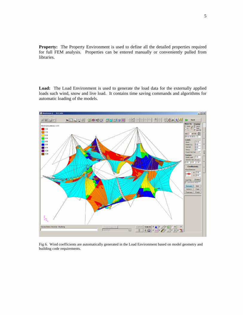
5 Property: The Property Environment is used to define all the detailed properties required for full FEM analysis. Properties can be entered manually or conveniently pulled from libraries. Load: The Load Environment is used to generate the load data for the externally applied loads such wind, snow and live load. It contains time saving commands and algorithms for automatic loading of the models.
Fig 6. Wind coefficients are automatically generated in the Load Environment based on model geometry and building code requirements.
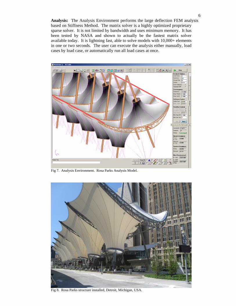
6Analysis: The Analysis Environment performs the large deflection FEM analysis based on Stiffness Method. The matrix solver is a highly optimized proprietary sparse solver. It is not limited by bandwidth and uses minimum memory. It has been tested by NASA and shown to actually be the fastest matrix solver available today. It is lightning fast, able to solve models with 10,000+ elements in one or two seconds. The user can execute the analysis either manually, load cases by load case, or automatically run all load cases at once.
Fig 7. Analysis Environment. Rosa Parks Analysis Model.
Fig 8. Rosa Parks structure installed, Detroit, Michigan, USA.
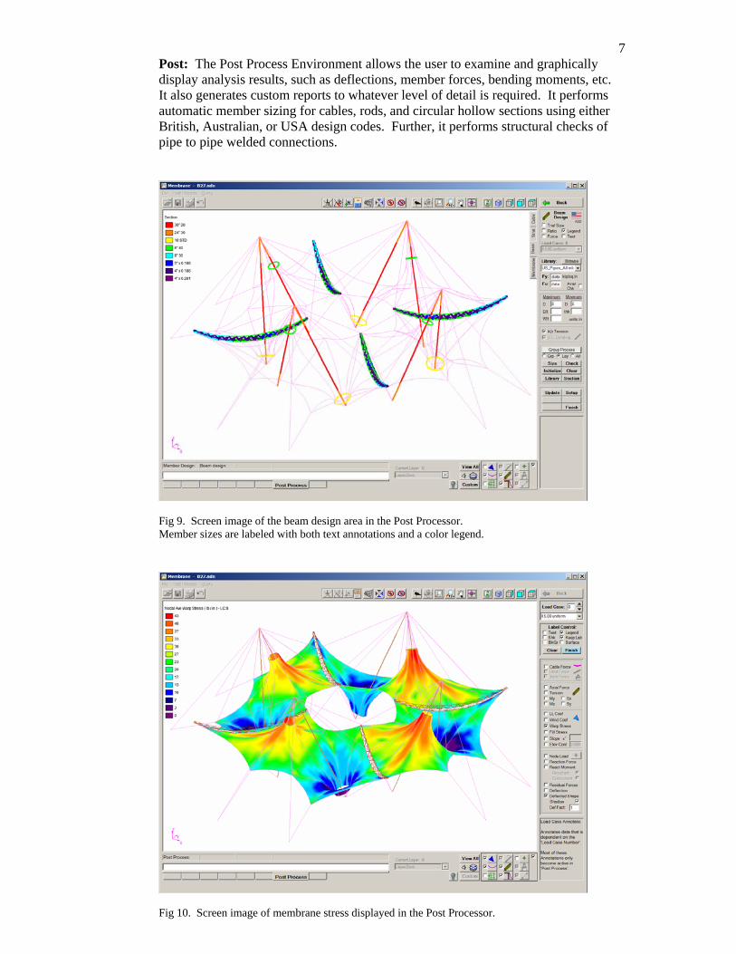
7Post: The Post Process Environment allows the user to examine and graphically display analysis results, such as deflections, member forces, bending moments, etc. It also generates custom reports to whatever level of detail is required. It performs automatic member sizing for cables, rods, and circular hollow sections using either British, Australian, or USA design codes. Further, it performs structural checks of pipe to pipe welded connections.
Fig 9. Screen image of the beam design area in the Post Processor. Member sizes are labeled with both text annotations and a color legend.
Fig 10. Screen image of membrane stress displayed in the Post Processor.
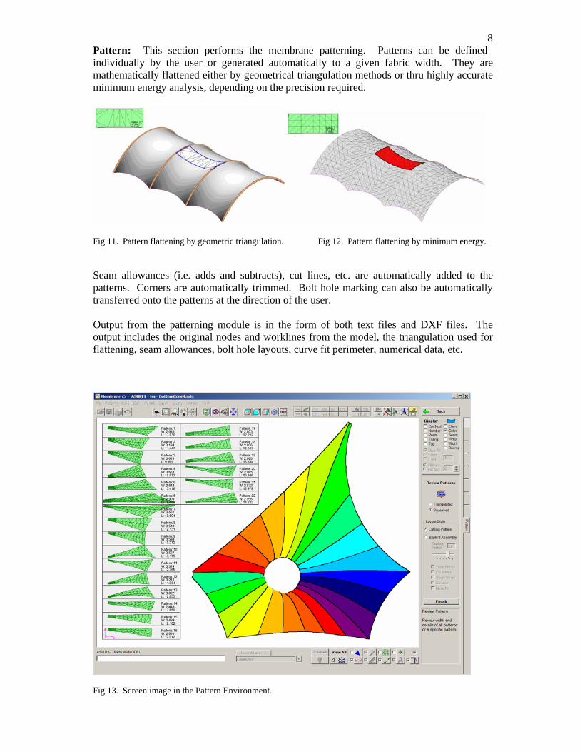
8Pattern: This section performs the membrane patterning. Patterns can be defined individually by the user or generated automatically to a given fabric width. They are mathematically flattened either by geometrical triangulation methods or thru highly accurate minimum energy analysis, depending on the precision required.
Fig 11. Pattern flattening by geometric triangulation. Fig 12. Pattern flattening by minimum energy. Seam allowances (i.e. adds and subtracts), cut lines, etc. are automatically added to the patterns. Corners are automatically trimmed. Bolt hole marking can also be automatically transferred onto the patterns at the direction of the user. Output from the patterning module is in the form of both text files and DXF files. The output includes the original nodes and worklines from the model, the triangulation used for flattening, seam allowances, bolt hole layouts, curve fit perimeter, numerical data, etc.
Fig 13. Screen image in the Pattern Environment.
9
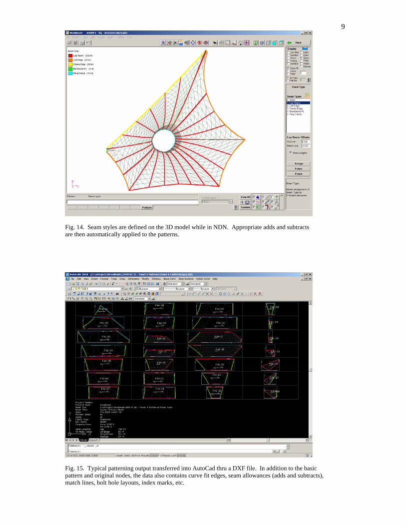
Fig. 14. Seam styles are defined on the 3D model while in NDN. Appropriate adds and subtracts are then automatically applied to the patterns.
Fig. 15. Typical patterning output transferred into AutoCad thru a DXF file. In addition to the basic pattern and original nodes, the data also contains curve fit edges, seam allowances (adds and subtracts), match lines, bolt hole layouts, index marks, etc.
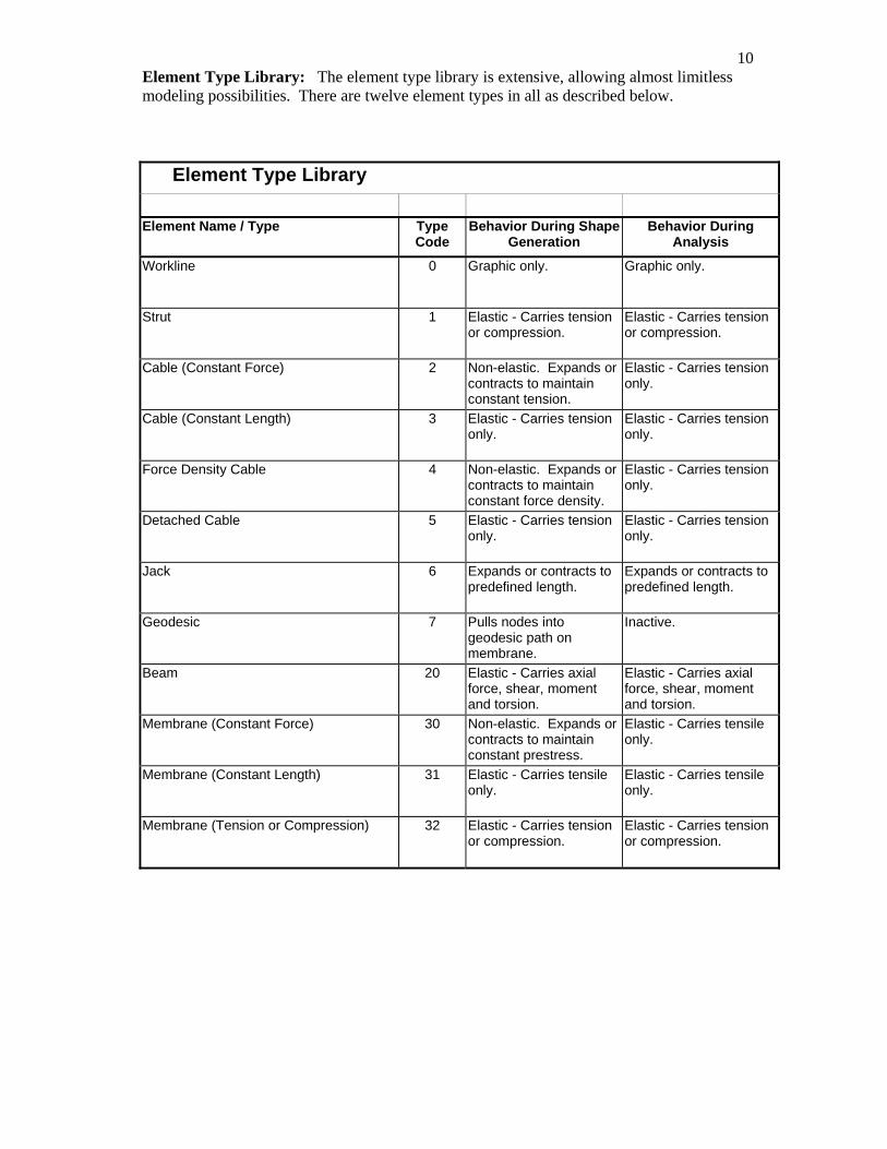
10Element Type Library: The element type library is extensive, allowing almost limitless modeling possibilities. There are twelve element types in all as described below.
Element Type Library
Element Name / Type Type Code
Behavior During Shape Generation
Behavior During Analysis
Workline 0 Graphic only. Graphic only.
Strut 1 Elastic - Carries tension or compression.
Elastic - Carries tension or compression.
Cable (Constant Force) 2 Non-elastic. Expands or contracts to maintain constant tension.
Elastic - Carries tension only.
Cable (Constant Length) 3 Elastic - Carries tension only.
Elastic - Carries tension only.
Force Density Cable 4 Non-elastic. Expands or contracts to maintain constant force density.
Elastic - Carries tension only.
Detached Cable 5 Elastic - Carries tension only.
Elastic - Carries tension only.
Jack 6 Expands or contracts to predefined length.
Expands or contracts to predefined length.
Geodesic 7 Pulls nodes into geodesic path on membrane.
Inactive.
Beam 20 Elastic - Carries axial force, shear, moment and torsion.
Elastic - Carries axial force, shear, moment and torsion.
Membrane (Constant Force) 30 Non-elastic. Expands or contracts to maintain constant prestress.
Elastic - Carries tensile only.
Membrane (Constant Length) 31 Elastic - Carries tensile only.
Elastic - Carries tensile only.
Membrane (Tension or Compression) 32 Elastic - Carries tension or compression.
Elastic - Carries tension or compression.
11NDN is currently used by many of the leading tensile membrane designers, engineering consultants and fabricators world wide.
Fig. 16. Whitsunday Shopping Center, Australia.
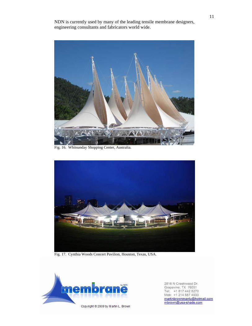
Fig. 17. Cynthia Woods Concert Pavilion, Houston, Texas, USA.