NDA-24282 ISSUE 1 - PDF.TEXTFILES.COMpdf.textfiles.com/manuals/TELECOM-F-R/NEC NEAX2400 IMX... ·...
485
NDA-24282 ISSUE 1 STOCK # 200874 CallCenterWorX-Enterprise ACD System Manual SEPTEMBER, 2000 NEC America, Inc. ®
Transcript of NDA-24282 ISSUE 1 - PDF.TEXTFILES.COMpdf.textfiles.com/manuals/TELECOM-F-R/NEC NEAX2400 IMX... ·...

NDA-24282ISSUE 1
STOCK # 200874
CallCenterWorX-EnterpriseACD System Manual
SEPTEMBER, 2000
NEC America, Inc.
®

LIABILITY DISCLAIMER
NEC America, Inc. reserves the right to change the specifications,functions, or features, at any time, without notice.
NEC America, Inc. has prepared this document for use by its em-ployees and customers. The information contained herein is theproperty of NEC America, Inc. and shall not be reproduced withoutprior written approval from NEC America, Inc.
NEAX and Dterm are registered trademarks of NEC Corporation.
CAUTION: The use of a monitoring, recording or listening deviceto eavesdrop, monitor, retrieve or record telephone conversationsor other sound activities, whether or not contemporaneous with itstransmission, may be illegal in certain circumstances under federalor state laws. Legal advice should be sought prior to implementingany practice that monitors or records any telephone conversation.Some federal and state laws require some form of notification to allparties to the telephone conversation, such as using a beep toneor other notification methods or require the consent of all parties tothe telephone conversation, prior to monitoring or recording a tele-phone conversation. Some of these laws incorporate strict penal-ties.
Copyright 2000
NEC America, Inc.
Printed in USA

ISSUE 1 ISSUE 2
PAGE No.ISSUE No.
1 2 3 4 5 6 7 8
i 1
ii 1
iii 1
iv 1
v 1
vi 1
vii 1
viii 1
ix 1
x 1
1 1
2 1
3 1
4 1
5 1
6 1
7 1
8 1
9 1
10 1
11 1
12 1
13 1
14 1
15 1
16 1
17 1
18 1
19 1
20 1
21 1
22 1
23 1
24 1
25 1
26 1
27 1
28 1
DATE SEPTEMBER, 2000 DATE
ISSUE 5 ISSUE 6
DATE DATE
NEAX2400 IMXCallCenterWorX-Enterprise ACD System Ma
ISSUE 3 ISSUE 4
29 1
30 1
31 1
32 1
33 1
34 1
35 1
36 1
37 1
38 1
39 1
40 1
41 1
42 1
43 1
44 1
45 1
46 1
47 1
48 1
49 1
50 1
51 1
52 1
53 1
54 1
55 1
56 1
57 1
58 1
59 1
60 1
61 1
62 1
63 1
64 1
65 1
66 1
PAGE No.ISSUE No.
1 2 3 4 5 6 7 8
DATE DATE
ISSUE 7 ISSUE 8
DATE DATE
nual Revision Sheet 1/7
NDA-24282

ISSUE 1 ISSUE 2 ISSUE 3 ISSUE 4
67 1
68 1
69 1
70 1
71 1
72 1
73 1
74 1
75 1
76 1
77 1
78 1
79 1
80 1
81 1
82 1
83 1
84 1
85 1
86 1
87 1
88 1
89 1
90 1
91 1
92 1
93 1
94 1
95 1
96 1
97 1
98 1
99 1
100 1
101 1
102 1
103 1
104 1
PAGE No.ISSUE No.
1 2 3 4 5 6 7 8
105 1
106 1
107 1
108 1
109 1
110 1
111 1
112 1
113 1
114 1
115 1
116 1
117 1
118 1
119 1
120 1
121 1
122 1
123 1
124 1
125 1
126 1
127 1
128 1
129 1
130 1
131 1
132 1
133 1
134 1
135 1
136 1
137 1
138 1
139 1
140 1
141 1
142 1
PAGE No.ISSUE No.
1 2 3 4 5 6 7 8
DATE SEPTEMBER, 2000 DATE DATE DATE
ISSUE 5 ISSUE 6 ISSUE 7 ISSUE 8
DATE DATE DATE DATE
NEAX2400 IMXCallCenterWorX-Enterprise ACD System Manual Revision Sheet 2/7
NDA-24282

ISSUE 1 ISSUE 2 ISSUE 3 ISSUE 4
143 1
144 1
145 1
146 1
147 1
148 1
149 1
150 1
151 1
152 1
153 1
154 1
155 1
156 1
157 1
158 1
159 1
160 1
161 1
162 1
163 1
164 1
165 1
166 1
167 1
168 1
169 1
170 1
171 1
172 1
173 1
174 1
175 1
176 1
177 1
178 1
179 1
180 1
PAGE No.ISSUE No.
1 2 3 4 5 6 7 8
181 1
182 1
183 1
184 1
185 1
186 1
187 1
188 1
189 1
190 1
191 1
192 1
193 1
194 1
195 1
196 1
197 1
198 1
199 1
200 1
201 1
202 1
203 1
204 1
205 1
206 1
207 1
208 1
209 1
210 1
211 1
212 1
213 1
214 1
215 1
216 1
217 1
218 1
PAGE No.ISSUE No.
1 2 3 4 5 6 7 8
DATE SEPTEMBER, 2000 DATE DATE DATE
ISSUE 5 ISSUE 6 ISSUE 7 ISSUE 8
DATE DATE DATE DATE
NEAX2400 IMXCallCenterWorX-Enterprise ACD System Manual Revision Sheet 3/7
NDA-24282

ISSUE 1 ISSUE 2 ISSUE 3 ISSUE 4
219 1
220 1
221 1
222 1
223 1
224 1
225 1
226 1
227 1
228 1
229 1
230 1
231 1
232 1
233 1
234 1
235 1
236 1
237 1
238 1
239 1
240 1
241 1
242 1
243 1
244 1
245 1
246 1
247 1
248 1
249 1
250 1
251 1
252 1
253 1
254 1
255 1
256 1
PAGE No.ISSUE No.
1 2 3 4 5 6 7 8
257 1
258 1
259 1
260 1
261 1
262 1
263 1
264 1
265 1
266 1
267 1
268 1
269 1
270 1
271 1
272 1
273 1
274 1
275 1
276 1
277 1
278 1
279 1
280 1
281 1
282 1
283 1
284 1
285 1
286 1
287 1
288 1
289 1
290 1
291 1
292 1
293 1
294 1
PAGE No.ISSUE No.
1 2 3 4 5 6 7 8
DATE SEPTEMBER, 2000 DATE DATE DATE
ISSUE 5 ISSUE 6 ISSUE 7 ISSUE 8
DATE DATE DATE DATE
NEAX2400 IMXCallCenterWorX-Enterprise ACD System Manual Revision Sheet 4/7
NDA-24282

ISSUE 1 ISSUE 2 ISSUE 3 ISSUE 4
295 1
296 1
297 1
298 1
299 1
300 1
301 1
302 1
303 1
304 1
305 1
306 1
307 1
308 1
309 1
310 1
311 1
312 1
313 1
314 1
315 1
316 1
317 1
318 1
319 1
320 1
321 1
322 1
323 1
324 1
325 1
326 1
327 1
328 1
329 1
330 1
331 1
332 1
PAGE No.ISSUE No.
1 2 3 4 5 6 7 8
333 1
334 1
335 1
336 1
337 1
338 1
339 1
340 1
341 1
342 1
343 1
344 1
345 1
346 1
347 1
348 1
349 1
350 1
351 1
352 1
353 1
354 1
355 1
356 1
357 1
358 1
359 1
360 1
361 1
362 1
363 1
364 1
365 1
366 1
367 1
368 1
369 1
370 1
PAGE No.ISSUE No.
1 2 3 4 5 6 7 8
DATE SEPTEMBER, 2000 DATE DATE DATE
ISSUE 5 ISSUE 6 ISSUE 7 ISSUE 8
DATE DATE DATE DATE
NEAX2400 IMXCallCenterWorX-Enterprise ACD System Manual Revision Sheet 5/7
NDA-24282

ISSUE 1 ISSUE 2 ISSUE 3 ISSUE 4
371 1
372 1
373 1
374 1
375 1
376 1
377 1
378 1
379 1
380 1
381 1
382 1
383 1
384 1
385 1
386 1
387 1
388 1
389 1
390 1
391 1
392 1
393 1
394 1
395 1
396 1
397 1
398 1
399 1
400 1
401 1
402 1
403 1
404 1
405 1
406 1
407 1
408 1
PAGE No.ISSUE No.
1 2 3 4 5 6 7 8
409 1
410 1
411 1
412 1
413 1
414 1
415 1
416 1
417 1
418 1
419 1
420 1
421 1
422 1
423 1
424 1
425 1
426 1
427 1
428 1
429 1
430 1
431 1
432 1
433 1
434 1
435 1
436 1
437 1
438 1
439 1
440 1
441 1
442 1
443 1
444 1
445 1
446 1
PAGE No.ISSUE No.
1 2 3 4 5 6 7 8
DATE SEPTEMBER, 2000 DATE DATE DATE
ISSUE 5 ISSUE 6 ISSUE 7 ISSUE 8
DATE DATE DATE DATE
NEAX2400 IMXCallCenterWorX-Enterprise ACD System Manual Revision Sheet 6/7
NDA-24282

ISSUE 1 ISSUE 2 ISSUE 3 ISSUE 4
447 1
448 1
449 1
450 1
451 1
452 1
453 1
454 1
455 1
456 1
457 1
458 1
459 1
460 1
461 1
462 1
463 1
464 1
465 1
466 1
PAGE No.ISSUE No.
1 2 3 4 5 6 7 8PAGE No.
ISSUE No.
1 2 3 4 5 6 7 8
DATE SEPTEMBER, 2000 DATE DATE DATE
ISSUE 5 ISSUE 6 ISSUE 7 ISSUE 8
DATE DATE DATE DATE
NEAX2400 IMXCallCenterWorX-Enterprise ACD System Manual Revision Sheet 7/7
NDA-24282

NDA-24282ISSUE 1
SEPTEMBER, 2000
NEAX2400 IMXCallCenterWorX-Enterprise
ACD System Manual
TABLE OF CONTENTS
Page
LIST OF FIGURES. . . . . . . . . . . . . . . . . . . . . . . . . . . . . . . . . . . . . . . . . . . . . . . . . . . . . . . . . . . . . . . . . . . . . . . . vii
LIST OF TABLES. . . . . . . . . . . . . . . . . . . . . . . . . . . . . . . . . . . . . . . . . . . . . . . . . . . . . . . . . . . . . . . . . . . . . . . . . ix
Chapter 1 Introduction . . . . . . . . . . . . . . . . . . . . . . . . . . . . . . . . . . . . . . . . . . . . . . . . . . . . . . . . . . . . . . . . . . 1
1. General . . . . . . . . . . . . . . . . . . . . . . . . . . . . . . . . . . . . . . . . . . . . . . . . . . . . . . . . . . . . . . . . . . . . . . . . . 11.1 Configuration of this Manual . . . . . . . . . . . . . . . . . . . . . . . . . . . . . . . . . . . . . . . . . . . . . . . . . . . . 11.2 Related Reference Manuals . . . . . . . . . . . . . . . . . . . . . . . . . . . . . . . . . . . . . . . . . . . . . . . . . . . . 21.3 Precaution on Using the ACD Features. . . . . . . . . . . . . . . . . . . . . . . . . . . . . . . . . . . . . . . . . . . . 2
Chapter 2 General Information . . . . . . . . . . . . . . . . . . . . . . . . . . . . . . . . . . . . . . . . . . . . . . . . . . . . . . . . . . . 3
1. General . . . . . . . . . . . . . . . . . . . . . . . . . . . . . . . . . . . . . . . . . . . . . . . . . . . . . . . . . . . . . . . . . . . . . . . . . 31.1 System Specifications . . . . . . . . . . . . . . . . . . . . . . . . . . . . . . . . . . . . . . . . . . . . . . . . . . . . . . . . . 31.2 Glossary of Terms . . . . . . . . . . . . . . . . . . . . . . . . . . . . . . . . . . . . . . . . . . . . . . . . . . . . . . . . . . . . 3
2. System Specifications . . . . . . . . . . . . . . . . . . . . . . . . . . . . . . . . . . . . . . . . . . . . . . . . . . . . . . . . . . . . . . 42.1 General . . . . . . . . . . . . . . . . . . . . . . . . . . . . . . . . . . . . . . . . . . . . . . . . . . . . . . . . . . . . . . . . . . . . 42.2 Functional Outline . . . . . . . . . . . . . . . . . . . . . . . . . . . . . . . . . . . . . . . . . . . . . . . . . . . . . . . . . . . . 52.3 System Configuration . . . . . . . . . . . . . . . . . . . . . . . . . . . . . . . . . . . . . . . . . . . . . . . . . . . . . . . . . 6
2.3.1 System Capacity . . . . . . . . . . . . . . . . . . . . . . . . . . . . . . . . . . . . . . . . . . . . . . . . . . . . . . . 92.4 MIS . . . . . . . . . . . . . . . . . . . . . . . . . . . . . . . . . . . . . . . . . . . . . . . . . . . . . . . . . . . . . . . . . . . . . . 102.5 Interface Between ACD and MIS. . . . . . . . . . . . . . . . . . . . . . . . . . . . . . . . . . . . . . . . . . . . . . . . 102.6 Equipment Related to ACD System. . . . . . . . . . . . . . . . . . . . . . . . . . . . . . . . . . . . . . . . . . . . . . 10
2.6.1 Agent Position . . . . . . . . . . . . . . . . . . . . . . . . . . . . . . . . . . . . . . . . . . . . . . . . . . . . . . . . 102.6.2 Supervisory Position . . . . . . . . . . . . . . . . . . . . . . . . . . . . . . . . . . . . . . . . . . . . . . . . . . . 13
3. Glossary of Terms . . . . . . . . . . . . . . . . . . . . . . . . . . . . . . . . . . . . . . . . . . . . . . . . . . . . . . . . . . . . . . . . 14
Chapter 3 Installation. . . . . . . . . . . . . . . . . . . . . . . . . . . . . . . . . . . . . . . . . . . . . . . . . . . . . . . . . . . . . . . . . . 19
1. General . . . . . . . . . . . . . . . . . . . . . . . . . . . . . . . . . . . . . . . . . . . . . . . . . . . . . . . . . . . . . . . . . . . . . . . . 19
2. Precautions . . . . . . . . . . . . . . . . . . . . . . . . . . . . . . . . . . . . . . . . . . . . . . . . . . . . . . . . . . . . . . . . . . . . . 192.1 Essential/Critical Information . . . . . . . . . . . . . . . . . . . . . . . . . . . . . . . . . . . . . . . . . . . . . . . . . . . 19
3. Installation Procedures. . . . . . . . . . . . . . . . . . . . . . . . . . . . . . . . . . . . . . . . . . . . . . . . . . . . . . . . . . . . . 213.1 Peripheral Equipment Installation . . . . . . . . . . . . . . . . . . . . . . . . . . . . . . . . . . . . . . . . . . . . . . . 21NAP-200-101 Installation of ACD Agent Position . . . . . . . . . . . . . . . . . . . . . . . . . . . . . . . . . . . . . . . . . 22NAP-200-102 Installation of ACD Supervisory Position . . . . . . . . . . . . . . . . . . . . . . . . . . . . . . . . . . . . 25NAP-200-103 Installation of MIS. . . . . . . . . . . . . . . . . . . . . . . . . . . . . . . . . . . . . . . . . . . . . . . . . . . . . . 28NAP-200-104 Installation of Emergency Recorder . . . . . . . . . . . . . . . . . . . . . . . . . . . . . . . . . . . . . . . . 29NAP-200-105 Installation of Announcement Machine . . . . . . . . . . . . . . . . . . . . . . . . . . . . . . . . . . . . . 30
NDA-24282 TABLE OF CONTENTSPage i
Revision 1.0

TABLE OF CONTENTS (CONTINUED)
PageNAP-200-106 Installation of IVR/Host. . . . . . . . . . . . . . . . . . . . . . . . . . . . . . . . . . . . . . . . . . . . . . . . . . 31
4. System Start-Up Procedure for Adding ACD Features . . . . . . . . . . . . . . . . . . . . . . . . . . . . . . . . . . . . 344.1 ACD Software Installation . . . . . . . . . . . . . . . . . . . . . . . . . . . . . . . . . . . . . . . . . . . . . . . . . . . . . 344.2 Basic Data Assignment for Start-Up . . . . . . . . . . . . . . . . . . . . . . . . . . . . . . . . . . . . . . . . . . . . . 36
5. Upgrading ACD System from NEAX2400 ICS to NEAX2400 IMX. . . . . . . . . . . . . . . . . . . . . . . . . . . . 375.1 Hardware and Software Requirements . . . . . . . . . . . . . . . . . . . . . . . . . . . . . . . . . . . . . . . . . . . 375.2 Upgrading Procedure. . . . . . . . . . . . . . . . . . . . . . . . . . . . . . . . . . . . . . . . . . . . . . . . . . . . . . . . . 39
Chapter 4 Switch Setting of ACD Circuit Cards. . . . . . . . . . . . . . . . . . . . . . . . . . . . . . . . . . . . . . . . . . . . . . 41
1. General . . . . . . . . . . . . . . . . . . . . . . . . . . . . . . . . . . . . . . . . . . . . . . . . . . . . . . . . . . . . . . . . . . . . . . . . 41
2. Explanation of ACD Circuit Cards . . . . . . . . . . . . . . . . . . . . . . . . . . . . . . . . . . . . . . . . . . . . . . . . . . . . 42PA-CP53 (CPU) . . . . . . . . . . . . . . . . . . . . . . . . . . . . . . . . . . . . . . . . . . . . . . . . . . . . . . . . . . . . . . . . . . 43PH-PC22 (EAPI) . . . . . . . . . . . . . . . . . . . . . . . . . . . . . . . . . . . . . . . . . . . . . . . . . . . . . . . . . . . . . . . . . . 49PH-PC27 (EAPI) . . . . . . . . . . . . . . . . . . . . . . . . . . . . . . . . . . . . . . . . . . . . . . . . . . . . . . . . . . . . . . . . . . 54PA-AL16 (ALMC) . . . . . . . . . . . . . . . . . . . . . . . . . . . . . . . . . . . . . . . . . . . . . . . . . . . . . . . . . . . . . . . . . 59PH-PC21 (APINT) . . . . . . . . . . . . . . . . . . . . . . . . . . . . . . . . . . . . . . . . . . . . . . . . . . . . . . . . . . . . . . . . . 64PA-PC56-A (COPY) . . . . . . . . . . . . . . . . . . . . . . . . . . . . . . . . . . . . . . . . . . . . . . . . . . . . . . . . . . . . . . . 68PA-CP54 (CPU) . . . . . . . . . . . . . . . . . . . . . . . . . . . . . . . . . . . . . . . . . . . . . . . . . . . . . . . . . . . . . . . . . . 72PA-ME34 (CRAM). . . . . . . . . . . . . . . . . . . . . . . . . . . . . . . . . . . . . . . . . . . . . . . . . . . . . . . . . . . . . . . . . 79PA-IO02-A (IOC) . . . . . . . . . . . . . . . . . . . . . . . . . . . . . . . . . . . . . . . . . . . . . . . . . . . . . . . . . . . . . . . . . . 83PH-BS16 (PBI) . . . . . . . . . . . . . . . . . . . . . . . . . . . . . . . . . . . . . . . . . . . . . . . . . . . . . . . . . . . . . . . . . . . 90PA-GT17 (SPGT) . . . . . . . . . . . . . . . . . . . . . . . . . . . . . . . . . . . . . . . . . . . . . . . . . . . . . . . . . . . . . . . . . 95PA-16ELCDD (ELC) . . . . . . . . . . . . . . . . . . . . . . . . . . . . . . . . . . . . . . . . . . . . . . . . . . . . . . . . . . . . . . . 99PA-16ELCH (16ELC) . . . . . . . . . . . . . . . . . . . . . . . . . . . . . . . . . . . . . . . . . . . . . . . . . . . . . . . . . . . . . 111PA-16ELCJ (16ELC) . . . . . . . . . . . . . . . . . . . . . . . . . . . . . . . . . . . . . . . . . . . . . . . . . . . . . . . . . . . . . . 124PA-4DATA (4DAT) . . . . . . . . . . . . . . . . . . . . . . . . . . . . . . . . . . . . . . . . . . . . . . . . . . . . . . . . . . . . . . . 135PA-4DATB (DAT) . . . . . . . . . . . . . . . . . . . . . . . . . . . . . . . . . . . . . . . . . . . . . . . . . . . . . . . . . . . . . . . . 145PA-4DTLA (4DTL). . . . . . . . . . . . . . . . . . . . . . . . . . . . . . . . . . . . . . . . . . . . . . . . . . . . . . . . . . . . . . . . 155PA-CC98 (ETHER) . . . . . . . . . . . . . . . . . . . . . . . . . . . . . . . . . . . . . . . . . . . . . . . . . . . . . . . . . . . . . . . 163PA-GT16 (MBB) . . . . . . . . . . . . . . . . . . . . . . . . . . . . . . . . . . . . . . . . . . . . . . . . . . . . . . . . . . . . . . . . . 170
Chapter 5 Office Data Design . . . . . . . . . . . . . . . . . . . . . . . . . . . . . . . . . . . . . . . . . . . . . . . . . . . . . . . . . . 175
1. General . . . . . . . . . . . . . . . . . . . . . . . . . . . . . . . . . . . . . . . . . . . . . . . . . . . . . . . . . . . . . . . . . . . . . . . 175
2. Basic Office Data Assignment . . . . . . . . . . . . . . . . . . . . . . . . . . . . . . . . . . . . . . . . . . . . . . . . . . . . . . 1752.1 Back-Up UCD . . . . . . . . . . . . . . . . . . . . . . . . . . . . . . . . . . . . . . . . . . . . . . . . . . . . . . . . . . . . . 1762.2 ACD In a Fusion Network Data Assignment . . . . . . . . . . . . . . . . . . . . . . . . . . . . . . . . . . . . . . 181
2.2.1 ACD Trunk In a Fusion Network . . . . . . . . . . . . . . . . . . . . . . . . . . . . . . . . . . . . . . . . . 1842.2.2 Multiple ACDPs In a FuSion Network . . . . . . . . . . . . . . . . . . . . . . . . . . . . . . . . . . . . . 186
3. ACD Service Feature . . . . . . . . . . . . . . . . . . . . . . . . . . . . . . . . . . . . . . . . . . . . . . . . . . . . . . . . . . . . . 196A-31A Abandoned Call Search - ACD . . . . . . . . . . . . . . . . . . . . . . . . . . . . . . . . . . . . . . . . . . . . . . . 199A-34A Assistance - ACD Agent - ACD. . . . . . . . . . . . . . . . . . . . . . . . . . . . . . . . . . . . . . . . . . . . . . . 200A-35A Automatic Answer - ACD . . . . . . . . . . . . . . . . . . . . . . . . . . . . . . . . . . . . . . . . . . . . . . . . . . . 202A-37A Availability - ACD Position - ACD . . . . . . . . . . . . . . . . . . . . . . . . . . . . . . . . . . . . . . . . . . . . . 204A-80A Announcements - ACD . . . . . . . . . . . . . . . . . . . . . . . . . . . . . . . . . . . . . . . . . . . . . . . . . . . . . 206A-85A Agent Personal Queue - ACD. . . . . . . . . . . . . . . . . . . . . . . . . . . . . . . . . . . . . . . . . . . . . . . . 208A-86A Auto Work Mode for PBX Calls - ACD . . . . . . . . . . . . . . . . . . . . . . . . . . . . . . . . . . . . . . . . . 211A-91A Analog ACD Position - ACD . . . . . . . . . . . . . . . . . . . . . . . . . . . . . . . . . . . . . . . . . . . . . . . . . 212
TABLE OF CONTENTS NDA-24282Page iiRevision 1.0

TABLE OF CONTENTS (CONTINUED)
PageA-93A Alternate Night CCV - ACD. . . . . . . . . . . . . . . . . . . . . . . . . . . . . . . . . . . . . . . . . . . . . . . . . . 214A-133A Agent Anywhere - ACD. . . . . . . . . . . . . . . . . . . . . . . . . . . . . . . . . . . . . . . . . . . . . . . . . . . . . 215B-20A Break Mode - ACD . . . . . . . . . . . . . . . . . . . . . . . . . . . . . . . . . . . . . . . . . . . . . . . . . . . . . . . . 217B-21A Bad Call Notifications - ACD . . . . . . . . . . . . . . . . . . . . . . . . . . . . . . . . . . . . . . . . . . . . . . . . . 219C-35A Call Distribution to Agents - ACD . . . . . . . . . . . . . . . . . . . . . . . . . . . . . . . . . . . . . . . . . . . . . 220C-67A Call Transfer to Split Queue - ACD. . . . . . . . . . . . . . . . . . . . . . . . . . . . . . . . . . . . . . . . . . . . 222C-68A Call Waiting Indication - LCD Display/CW Lamp - ACD . . . . . . . . . . . . . . . . . . . . . . . . . . . . 224C-70A Calling Party Identification - ACD . . . . . . . . . . . . . . . . . . . . . . . . . . . . . . . . . . . . . . . . . . . . . 225C-108A Call Control Vector - ACD. . . . . . . . . . . . . . . . . . . . . . . . . . . . . . . . . . . . . . . . . . . . . . . . . . . 227C-110A Call Waiting Lamp with Chime - ACD . . . . . . . . . . . . . . . . . . . . . . . . . . . . . . . . . . . . . . . . . . 235C-127A Call Forwarding - Split - ACD . . . . . . . . . . . . . . . . . . . . . . . . . . . . . . . . . . . . . . . . . . . . . . . . 236C-191A Call Recover - ACD. . . . . . . . . . . . . . . . . . . . . . . . . . . . . . . . . . . . . . . . . . . . . . . . . . . . . . . . 238C-199A Connection Displays - ACD . . . . . . . . . . . . . . . . . . . . . . . . . . . . . . . . . . . . . . . . . . . . . . . . . 239D-133A Do Not Disturb - Split - ACD . . . . . . . . . . . . . . . . . . . . . . . . . . . . . . . . . . . . . . . . . . . . . . . . . 242E-6A Emergency/Recorder - ACD . . . . . . . . . . . . . . . . . . . . . . . . . . . . . . . . . . . . . . . . . . . . . . . . . 244F-10A Function Groups (Splits) - ACD . . . . . . . . . . . . . . . . . . . . . . . . . . . . . . . . . . . . . . . . . . . . . . 248F-25A Flexible ID Codes - ACD. . . . . . . . . . . . . . . . . . . . . . . . . . . . . . . . . . . . . . . . . . . . . . . . . . . . 249H-20A Holiday Scheduling - ACD . . . . . . . . . . . . . . . . . . . . . . . . . . . . . . . . . . . . . . . . . . . . . . . . . . 251H-31A Hot Split - ACD . . . . . . . . . . . . . . . . . . . . . . . . . . . . . . . . . . . . . . . . . . . . . . . . . . . . . . . . . . . 252I-99A Infolink Data Messages - ACD . . . . . . . . . . . . . . . . . . . . . . . . . . . . . . . . . . . . . . . . . . . . . . . 254L-19A Logon/Logoff Position - ACD . . . . . . . . . . . . . . . . . . . . . . . . . . . . . . . . . . . . . . . . . . . . . . . . 257L-48A Language Default - ACD. . . . . . . . . . . . . . . . . . . . . . . . . . . . . . . . . . . . . . . . . . . . . . . . . . . . 259L-92A Logoff Warning - ACD. . . . . . . . . . . . . . . . . . . . . . . . . . . . . . . . . . . . . . . . . . . . . . . . . . . . . . 260M-28A Monitoring - ACD Supervisor - ACD . . . . . . . . . . . . . . . . . . . . . . . . . . . . . . . . . . . . . . . . . . . 261M-29A Multiple Customer Groups - ACD . . . . . . . . . . . . . . . . . . . . . . . . . . . . . . . . . . . . . . . . . . . . . 264M-79A Multiple Supervisor Groups (Splits) - ACD . . . . . . . . . . . . . . . . . . . . . . . . . . . . . . . . . . . . . . 266M-88A MIS Operator Selection - ACD . . . . . . . . . . . . . . . . . . . . . . . . . . . . . . . . . . . . . . . . . . . . . . . 268M-89A Monitor Me - ACD . . . . . . . . . . . . . . . . . . . . . . . . . . . . . . . . . . . . . . . . . . . . . . . . . . . . . . . . . 269M-90A Multi-Split Agent - ACD. . . . . . . . . . . . . . . . . . . . . . . . . . . . . . . . . . . . . . . . . . . . . . . . . . . . . 271N-12A Night Service - ACD . . . . . . . . . . . . . . . . . . . . . . . . . . . . . . . . . . . . . . . . . . . . . . . . . . . . . . . 275N-14A Non-ACD Call - ACD. . . . . . . . . . . . . . . . . . . . . . . . . . . . . . . . . . . . . . . . . . . . . . . . . . . . . . . 277O-10A Overflow - ACD. . . . . . . . . . . . . . . . . . . . . . . . . . . . . . . . . . . . . . . . . . . . . . . . . . . . . . . . . . . 278O-19A Overflow Outside - ACD . . . . . . . . . . . . . . . . . . . . . . . . . . . . . . . . . . . . . . . . . . . . . . . . . . . . 279P-21A Priority Queuing - ACD . . . . . . . . . . . . . . . . . . . . . . . . . . . . . . . . . . . . . . . . . . . . . . . . . . . . . 280P-40A Pilot Numbers - ACD. . . . . . . . . . . . . . . . . . . . . . . . . . . . . . . . . . . . . . . . . . . . . . . . . . . . . . . 282P-45A Personal Emergency and Assist - ACD . . . . . . . . . . . . . . . . . . . . . . . . . . . . . . . . . . . . . . . . 283Q-1A Queuing - ACD . . . . . . . . . . . . . . . . . . . . . . . . . . . . . . . . . . . . . . . . . . . . . . . . . . . . . . . . . . . 285R-19A Release - ACD Position - ACD . . . . . . . . . . . . . . . . . . . . . . . . . . . . . . . . . . . . . . . . . . . . . . . 288R-145A Ring Delay - ACD . . . . . . . . . . . . . . . . . . . . . . . . . . . . . . . . . . . . . . . . . . . . . . . . . . . . . . . . . 289S-91A Splits - ACD . . . . . . . . . . . . . . . . . . . . . . . . . . . . . . . . . . . . . . . . . . . . . . . . . . . . . . . . . . . . . 290S-97A Split Display - ACD Position - ACD. . . . . . . . . . . . . . . . . . . . . . . . . . . . . . . . . . . . . . . . . . . . 294S-98A Split Selection - ACD . . . . . . . . . . . . . . . . . . . . . . . . . . . . . . . . . . . . . . . . . . . . . . . . . . . . . . 295S-108A Stranded Call Routing - ACD . . . . . . . . . . . . . . . . . . . . . . . . . . . . . . . . . . . . . . . . . . . . . . . . 296T-24A Trunk Trouble Report - MIS - ACD . . . . . . . . . . . . . . . . . . . . . . . . . . . . . . . . . . . . . . . . . . . . 297T-49A Tally Count - ACD. . . . . . . . . . . . . . . . . . . . . . . . . . . . . . . . . . . . . . . . . . . . . . . . . . . . . . . . . 298T-50A Time of Day/Week Routing - ACD . . . . . . . . . . . . . . . . . . . . . . . . . . . . . . . . . . . . . . . . . . . . 299T-51A Tally-Oh Codes - ACD . . . . . . . . . . . . . . . . . . . . . . . . . . . . . . . . . . . . . . . . . . . . . . . . . . . . . 300T-85A Tally Required - ACD . . . . . . . . . . . . . . . . . . . . . . . . . . . . . . . . . . . . . . . . . . . . . . . . . . . . . . 305
NDA-24282 TABLE OF CONTENTSPage iii
Revision 1.0

TABLE OF CONTENTS (CONTINUED)
PageV-10 VARIABLE QUEUEING . . . . . . . . . . . . . . . . . . . . . . . . . . . . . . . . . . . . . . . . . . . . . . . . . . . . 306W-5A Work Mode - ACD. . . . . . . . . . . . . . . . . . . . . . . . . . . . . . . . . . . . . . . . . . . . . . . . . . . . . . . . . 307W-6A Work Mode Time Limit - ACD . . . . . . . . . . . . . . . . . . . . . . . . . . . . . . . . . . . . . . . . . . . . . . . . 309Z-1A Zip Tone - ACD. . . . . . . . . . . . . . . . . . . . . . . . . . . . . . . . . . . . . . . . . . . . . . . . . . . . . . . . . . . 310
Chapter 6 ACD Service Features Functional Test Procedures . . . . . . . . . . . . . . . . . . . . . . . . . . . . . . . . . 311NAP-215-101 ACD Incoming . . . . . . . . . . . . . . . . . . . . . . . . . . . . . . . . . . . . . . . . . . . . . . . . . . . . . . . 314NAP-215-102 Call Distribution to Agents . . . . . . . . . . . . . . . . . . . . . . . . . . . . . . . . . . . . . . . . . . . . . . 316NAP-215-103 Priority Processing . . . . . . . . . . . . . . . . . . . . . . . . . . . . . . . . . . . . . . . . . . . . . . . . . . . . 317NAP-215-104 Automatic Call Distribution . . . . . . . . . . . . . . . . . . . . . . . . . . . . . . . . . . . . . . . . . . . . . . 318NAP-215-105 Delay Announcement . . . . . . . . . . . . . . . . . . . . . . . . . . . . . . . . . . . . . . . . . . . . . . . . . . 319NAP-215-106 Center Closed Announcement . . . . . . . . . . . . . . . . . . . . . . . . . . . . . . . . . . . . . . . . . . . 320NAP-215-107 Overflow . . . . . . . . . . . . . . . . . . . . . . . . . . . . . . . . . . . . . . . . . . . . . . . . . . . . . . . . . . . . 321NAP-215-108 Emergency Recorder . . . . . . . . . . . . . . . . . . . . . . . . . . . . . . . . . . . . . . . . . . . . . . . . . . 322NAP-215-109 After Call Work (Manual) . . . . . . . . . . . . . . . . . . . . . . . . . . . . . . . . . . . . . . . . . . . . . . . 323NAP-215-110 After Call Work (Automatic) . . . . . . . . . . . . . . . . . . . . . . . . . . . . . . . . . . . . . . . . . . . . . 324NAP-215-111 Assistance . . . . . . . . . . . . . . . . . . . . . . . . . . . . . . . . . . . . . . . . . . . . . . . . . . . . . . . . . . 325NAP-215-112 Auxiliary Work . . . . . . . . . . . . . . . . . . . . . . . . . . . . . . . . . . . . . . . . . . . . . . . . . . . . . . . 326NAP-215-113 Monitoring–ACD Supervisor. . . . . . . . . . . . . . . . . . . . . . . . . . . . . . . . . . . . . . . . . . . . . 327NAP-215-114 Night Service . . . . . . . . . . . . . . . . . . . . . . . . . . . . . . . . . . . . . . . . . . . . . . . . . . . . . . . . 328NAP-215-115 Abandoned Call Search . . . . . . . . . . . . . . . . . . . . . . . . . . . . . . . . . . . . . . . . . . . . . . . . 330NAP-215-116 Trunk Trouble Report . . . . . . . . . . . . . . . . . . . . . . . . . . . . . . . . . . . . . . . . . . . . . . . . . . 331
Chapter 7 PBX and ACD Command Programming. . . . . . . . . . . . . . . . . . . . . . . . . . . . . . . . . . . . . . . . . . 333
1. General . . . . . . . . . . . . . . . . . . . . . . . . . . . . . . . . . . . . . . . . . . . . . . . . . . . . . . . . . . . . . . . . . . . . . . . 333
2. Commands. . . . . . . . . . . . . . . . . . . . . . . . . . . . . . . . . . . . . . . . . . . . . . . . . . . . . . . . . . . . . . . . . . . . . 3332.1 NEAX2400 IMX Commands . . . . . . . . . . . . . . . . . . . . . . . . . . . . . . . . . . . . . . . . . . . . . . . . . . 333
ASYD Assignment of System Data . . . . . . . . . . . . . . . . . . . . . . . . . . . . . . . . . . . . . . . . . . . 334ASYDL Assignment of System Data into Local DM (LDM) . . . . . . . . . . . . . . . . . . . . . . . . . . 338ASYDN Assignment of System Data in NDM. . . . . . . . . . . . . . . . . . . . . . . . . . . . . . . . . . . . . 341AOKC Assignment of OAI Key Code . . . . . . . . . . . . . . . . . . . . . . . . . . . . . . . . . . . . . . . . . . 342ASDT Assignment of Station Data. . . . . . . . . . . . . . . . . . . . . . . . . . . . . . . . . . . . . . . . . . . . 344ASFC Assignment of Service Feature Restriction Class Data . . . . . . . . . . . . . . . . . . . . . . 346AKYD Assignment of Key Data for Dterm . . . . . . . . . . . . . . . . . . . . . . . . . . . . . . . . . . . . . . 348AMNO Assignment of Monitored Number. . . . . . . . . . . . . . . . . . . . . . . . . . . . . . . . . . . . . . . 354AMNOL Assignment of Monitored Number for LDM. . . . . . . . . . . . . . . . . . . . . . . . . . . . . . . . 356AMNON Assignment of Monitored Number for NDM . . . . . . . . . . . . . . . . . . . . . . . . . . . . . . . 358ACNO Assignment of Conversion Number Data . . . . . . . . . . . . . . . . . . . . . . . . . . . . . . . . . 360ACNOL Assignment of Conversion Number Data for LDM . . . . . . . . . . . . . . . . . . . . . . . . . . 362ACNON Assignment of Conversion Number Data for NDM . . . . . . . . . . . . . . . . . . . . . . . . . . 364AADT Assignment of Announcement/Dictation Trunks . . . . . . . . . . . . . . . . . . . . . . . . . . . . 366AADTN Assignment of Announcement/Dictation Trunks for NDM. . . . . . . . . . . . . . . . . . . . . 368ALGNN Assignment of Telephone Number Data for NDM. . . . . . . . . . . . . . . . . . . . . . . . . . . 370ALGSN Assignment of Telephone Station Data for NDM . . . . . . . . . . . . . . . . . . . . . . . . . . . 372
2.2 ACD Commands . . . . . . . . . . . . . . . . . . . . . . . . . . . . . . . . . . . . . . . . . . . . . . . . . . . . . . . . . . . 3762.2.1 Command Relationships . . . . . . . . . . . . . . . . . . . . . . . . . . . . . . . . . . . . . . . . . . . . . . . 377
2.3 Setting Up the ACD . . . . . . . . . . . . . . . . . . . . . . . . . . . . . . . . . . . . . . . . . . . . . . . . . . . . . . . . . 378ACDTN Assignment of ACD Tenant Data . . . . . . . . . . . . . . . . . . . . . . . . . . . . . . . . . . . . . . . 380
TABLE OF CONTENTS NDA-24282Page ivRevision 1.0

TABLE OF CONTENTS (CONTINUED)
PageACDSPL Assignment of ACD Split Data . . . . . . . . . . . . . . . . . . . . . . . . . . . . . . . . . . . . . . . . . 384ACDLOG Assignment of ACD Receiver ID Code. . . . . . . . . . . . . . . . . . . . . . . . . . . . . . . . . . . 389ACDPSN Assignment of ACD Position Data . . . . . . . . . . . . . . . . . . . . . . . . . . . . . . . . . . . . . . 392ACDCCV Assignment of ACD CCV Data . . . . . . . . . . . . . . . . . . . . . . . . . . . . . . . . . . . . . . . . . 395ACDPLT Assignment of ACD Monitor Number . . . . . . . . . . . . . . . . . . . . . . . . . . . . . . . . . . . . 400ACDTG Assignment of ACD Trunk Group Data . . . . . . . . . . . . . . . . . . . . . . . . . . . . . . . . . . . 402ACDANA Assignment of ACD Analog Split Access Code . . . . . . . . . . . . . . . . . . . . . . . . . . . . 404ACDIVR Assignment of ACD IVR Data . . . . . . . . . . . . . . . . . . . . . . . . . . . . . . . . . . . . . . . . . . 406ACDHS Assignment of ACD Holiday Schedule . . . . . . . . . . . . . . . . . . . . . . . . . . . . . . . . . . . 408ACDHC Assignment of ACD Holiday Calendar . . . . . . . . . . . . . . . . . . . . . . . . . . . . . . . . . . . 411ACDWS Assignment of ACD Week Schedule. . . . . . . . . . . . . . . . . . . . . . . . . . . . . . . . . . . . . 414ACDCOM ACD Communications Data. . . . . . . . . . . . . . . . . . . . . . . . . . . . . . . . . . . . . . . . . . . 417 System Information . . . . . . . . . . . . . . . . . . . . . . . . . . . . . . . . . . . . . . . . . . . . . . . . . . 418 ACD Backup . . . . . . . . . . . . . . . . . . . . . . . . . . . . . . . . . . . . . . . . . . . . . . . . . . . . . . . 422
Chapter 8 System Operations . . . . . . . . . . . . . . . . . . . . . . . . . . . . . . . . . . . . . . . . . . . . . . . . . . . . . . . . . . 425
1. General . . . . . . . . . . . . . . . . . . . . . . . . . . . . . . . . . . . . . . . . . . . . . . . . . . . . . . . . . . . . . . . . . . . . . . . 425
2. Operation of Dterm Agent Position/Supervisory Position. . . . . . . . . . . . . . . . . . . . . . . . . . . . . . . . . . 4262.1 Log On/Log Off . . . . . . . . . . . . . . . . . . . . . . . . . . . . . . . . . . . . . . . . . . . . . . . . . . . . . . . . . . . . 4262.2 Answer Mode. . . . . . . . . . . . . . . . . . . . . . . . . . . . . . . . . . . . . . . . . . . . . . . . . . . . . . . . . . . . . . 4282.3 Work Mode . . . . . . . . . . . . . . . . . . . . . . . . . . . . . . . . . . . . . . . . . . . . . . . . . . . . . . . . . . . . . . . 4292.4 Break Mode . . . . . . . . . . . . . . . . . . . . . . . . . . . . . . . . . . . . . . . . . . . . . . . . . . . . . . . . . . . . . . . 4302.5 Tally Count. . . . . . . . . . . . . . . . . . . . . . . . . . . . . . . . . . . . . . . . . . . . . . . . . . . . . . . . . . . . . . . . 4312.6 Trunk Trouble Report. . . . . . . . . . . . . . . . . . . . . . . . . . . . . . . . . . . . . . . . . . . . . . . . . . . . . . . . 4312.7 Call Transfer . . . . . . . . . . . . . . . . . . . . . . . . . . . . . . . . . . . . . . . . . . . . . . . . . . . . . . . . . . . . . . 4322.8 Night Service . . . . . . . . . . . . . . . . . . . . . . . . . . . . . . . . . . . . . . . . . . . . . . . . . . . . . . . . . . . . . . 4322.9 Assistance . . . . . . . . . . . . . . . . . . . . . . . . . . . . . . . . . . . . . . . . . . . . . . . . . . . . . . . . . . . . . . . . 4332.10 Emergency/Recorder. . . . . . . . . . . . . . . . . . . . . . . . . . . . . . . . . . . . . . . . . . . . . . . . . . . . . . . . 4332.11 Monitoring/Supervisory Override . . . . . . . . . . . . . . . . . . . . . . . . . . . . . . . . . . . . . . . . . . . . . . . 434
3. ACD System Restart Processing . . . . . . . . . . . . . . . . . . . . . . . . . . . . . . . . . . . . . . . . . . . . . . . . . . . . 434
Chapter 9 System Maintenance . . . . . . . . . . . . . . . . . . . . . . . . . . . . . . . . . . . . . . . . . . . . . . . . . . . . . . . . 435
1. General . . . . . . . . . . . . . . . . . . . . . . . . . . . . . . . . . . . . . . . . . . . . . . . . . . . . . . . . . . . . . . . . . . . . . . . 435
2. Maintenance. . . . . . . . . . . . . . . . . . . . . . . . . . . . . . . . . . . . . . . . . . . . . . . . . . . . . . . . . . . . . . . . . . . . 4362.1 Daily Maintenance . . . . . . . . . . . . . . . . . . . . . . . . . . . . . . . . . . . . . . . . . . . . . . . . . . . . . . . . . . 436
2.1.1 The Relationship between System Messages and Lamp Indications . . . . . . . . . . . . . 436
3. System Messages . . . . . . . . . . . . . . . . . . . . . . . . . . . . . . . . . . . . . . . . . . . . . . . . . . . . . . . . . . . . . . . 4373.1 System Messages and Their Meanings. . . . . . . . . . . . . . . . . . . . . . . . . . . . . . . . . . . . . . . . . . 4373.2 Message Detail Data . . . . . . . . . . . . . . . . . . . . . . . . . . . . . . . . . . . . . . . . . . . . . . . . . . . . . . . . 438
3.2.1 Message Detail Data of System Message “4-R” . . . . . . . . . . . . . . . . . . . . . . . . . . . . . 4383.2.2 Message Detail Data of System Message “5-Q” . . . . . . . . . . . . . . . . . . . . . . . . . . . . . 4403.2.3 Message Detail Data of System Message “6-H” . . . . . . . . . . . . . . . . . . . . . . . . . . . . . 4413.2.4 Message Detail Data of System Message “26-V” . . . . . . . . . . . . . . . . . . . . . . . . . . . . 447
4. Fault Diagnostics . . . . . . . . . . . . . . . . . . . . . . . . . . . . . . . . . . . . . . . . . . . . . . . . . . . . . . . . . . . . . . . . 4484.1 Fault Information and Fault Diagnostics . . . . . . . . . . . . . . . . . . . . . . . . . . . . . . . . . . . . . . . . . 4484.2 Diagnostics from System Messages . . . . . . . . . . . . . . . . . . . . . . . . . . . . . . . . . . . . . . . . . . . . 449
NDA-24282 TABLE OF CONTENTSPage v
Revision 1.0

TABLE OF CONTENTS (CONTINUED)
Page4.2.1 TCP/IP Link Failure . . . . . . . . . . . . . . . . . . . . . . . . . . . . . . . . . . . . . . . . . . . . . . . . . . . 4504.2.2 Bad Call Notification. . . . . . . . . . . . . . . . . . . . . . . . . . . . . . . . . . . . . . . . . . . . . . . . . . . 451
5. Fault Recovery Procedure . . . . . . . . . . . . . . . . . . . . . . . . . . . . . . . . . . . . . . . . . . . . . . . . . . . . . . . . . 4515.1 Before Starting Fault Recovery . . . . . . . . . . . . . . . . . . . . . . . . . . . . . . . . . . . . . . . . . . . . . . . . 4515.2 ACD SYSTEM FAULT RECOVERY PROCEDURES . . . . . . . . . . . . . . . . . . . . . . . . . . . . . . . 4515.3 MIS Fault Recovery Procedures . . . . . . . . . . . . . . . . . . . . . . . . . . . . . . . . . . . . . . . . . . . . . . . 452
Appendix A Glossary . . . . . . . . . . . . . . . . . . . . . . . . . . . . . . . . . . . . . . . . . . . . . . . . . . . . . . . . . . . . . . . . . 453
Appendix B Field Values for ACD Screens . . . . . . . . . . . . . . . . . . . . . . . . . . . . . . . . . . . . . . . . . . . . . . . . 455
Appendix C ACD Service in Fusion Network . . . . . . . . . . . . . . . . . . . . . . . . . . . . . . . . . . . . . . . . . . . . . . . 463
TABLE OF CONTENTS NDA-24282Page viRevision 1.0

LIST OF FIGURES
Figure Title Page
Figure 2-1 Functional Outline of NEAX2400 CallCenterWorX-Enterprise ACD System . . . . . . . . . . . . . 4Figure 2-2 Block Diagram of ACD System (Single CPU Configuration) . . . . . . . . . . . . . . . . . . . . . . . . . . 7Figure 2-3 Block Diagram of ACD System (Dual CPU Configuration) . . . . . . . . . . . . . . . . . . . . . . . . . . . 8Figure 2-4 Outer View of Dterm Series III Agent Position . . . . . . . . . . . . . . . . . . . . . . . . . . . . . . . . . . . 11Figure 2-5 Over View of Dterm Series E Agent Position . . . . . . . . . . . . . . . . . . . . . . . . . . . . . . . . . . . . 12Figure 2-6 Supervisory Positions . . . . . . . . . . . . . . . . . . . . . . . . . . . . . . . . . . . . . . . . . . . . . . . . . . . . . . 13Figure 2-7 NEAX2400 CallCenterWorX-Enterprise ACD System Configuration . . . . . . . . . . . . . . . . . . 14Figure 2-8 ACD Group Configuration . . . . . . . . . . . . . . . . . . . . . . . . . . . . . . . . . . . . . . . . . . . . . . . . . . . 15Figure 2-9 Concept of Operation Mode . . . . . . . . . . . . . . . . . . . . . . . . . . . . . . . . . . . . . . . . . . . . . . . . . 17Figure 3-1 Static Caution Indication . . . . . . . . . . . . . . . . . . . . . . . . . . . . . . . . . . . . . . . . . . . . . . . . . . . . 19Figure 3-2 3M Model 8012 Portable Field Service Kit . . . . . . . . . . . . . . . . . . . . . . . . . . . . . . . . . . . . . . 20Figure 3-3 Peripheral Equipment Installation Procedures . . . . . . . . . . . . . . . . . . . . . . . . . . . . . . . . . . . 21Figure 3-4 Connection of ACD Agent Position . . . . . . . . . . . . . . . . . . . . . . . . . . . . . . . . . . . . . . . . . . . . 22Figure 3-5 Key Pads on ACD Agent Position Keyboard (Dterm Series III) . . . . . . . . . . . . . . . . . . . . . . 23Figure 3-6 Key Pads on ACD Agent Position Keyboard (Dterm Series E) . . . . . . . . . . . . . . . . . . . . . . . 24Figure 3-7 Connection of ACD Supervisory Position . . . . . . . . . . . . . . . . . . . . . . . . . . . . . . . . . . . . . . . 25Figure 3-8 Key Pads on Supervisory Position Keyboard (Dterm Series III) . . . . . . . . . . . . . . . . . . . . . . 26Figure 3-9 Key Pads on Supervisory Position Keyboard (Dterm Series E) . . . . . . . . . . . . . . . . . . . . . . 27Figure 3-10 Cable Connection between MIS and PBX . . . . . . . . . . . . . . . . . . . . . . . . . . . . . . . . . . . . . . 28Figure 3-11 Connection of Emergency Recorder (When Emergency Recorder Has Starting Terminal) 29Figure 3-12 Connection of Emergency Recorder (When Emergency Recorder Does Not Have
Starting Terminal) . . . . . . . . . . . . . . . . . . . . . . . . . . . . . . . . . . . . . . . . . . . . . . . . . . . . . . . . . 29Figure 3-13 Connection of Announcement Machine . . . . . . . . . . . . . . . . . . . . . . . . . . . . . . . . . . . . . . . . 30Figure 3-14 System Configuration (when IVR/Host is installed) . . . . . . . . . . . . . . . . . . . . . . . . . . . . . . . 31Figure 3-15 Connection of Host . . . . . . . . . . . . . . . . . . . . . . . . . . . . . . . . . . . . . . . . . . . . . . . . . . . . . . . . 32Figure 3-16 Connection of IVR . . . . . . . . . . . . . . . . . . . . . . . . . . . . . . . . . . . . . . . . . . . . . . . . . . . . . . . . . 33Figure 3-17 Hardware and Software Upgrading Requirements . . . . . . . . . . . . . . . . . . . . . . . . . . . . . . . . 37Figure 4-1 RS Connector Leads Accommodation . . . . . . . . . . . . . . . . . . . . . . . . . . . . . . . . . . . . . . . . . 88Figure 4-2 Position in IMGdxh . . . . . . . . . . . . . . . . . . . . . . . . . . . . . . . . . . . . . . . . . . . . . . . . . . . . . . . . 95Figure 4-3 LT Connector Leads Accommodation of PIMU-A (1/2) . . . . . . . . . . . . . . . . . . . . . . . . . . . . 103Figure 4-3 LT Connector Leads Accommodation of PIMU-A (2/2) . . . . . . . . . . . . . . . . . . . . . . . . . . . . 104Figure 4-4 LT Connector Leads Accommodation of PIMB (1/2) . . . . . . . . . . . . . . . . . . . . . . . . . . . . . 105Figure 4-4 LT Connector Leads Accommodation of PIMB (2/2) . . . . . . . . . . . . . . . . . . . . . . . . . . . . . 106Figure 4-5 ELC Connector Leads Accommodation of PIMB (1/2) . . . . . . . . . . . . . . . . . . . . . . . . . . . . 107Figure 4-5 ELC Connector Leads Accommodation of PIMB (2/2) . . . . . . . . . . . . . . . . . . . . . . . . . . . . 108Figure 4-6 Connection Diagram . . . . . . . . . . . . . . . . . . . . . . . . . . . . . . . . . . . . . . . . . . . . . . . . . . . . . . 109Figure 4-7 LT Connector Leads Accommodation of PIMU-A (1 of 3) . . . . . . . . . . . . . . . . . . . . . . . . . . 116Figure 4-7 LT Connector Leads Accommodation of PIMU-A (2 of 3) . . . . . . . . . . . . . . . . . . . . . . . . . . 117Figure 4-7 LT Connector Leads Accommodation of PIMU-A (3 of 3) . . . . . . . . . . . . . . . . . . . . . . . . . . 118Figure 4-8 LT Connector Leads Accommodation of PIMB (1 of 3) . . . . . . . . . . . . . . . . . . . . . . . . . . . 119Figure 4-8 LT Connector Leads Accommodation of PIMB (2 of 3) . . . . . . . . . . . . . . . . . . . . . . . . . . . 120Figure 4-8 LT Connector Leads Accommodation of PIMB (3 of 3) . . . . . . . . . . . . . . . . . . . . . . . . . . . 121Figure 4-9 Connecting Route Diagram . . . . . . . . . . . . . . . . . . . . . . . . . . . . . . . . . . . . . . . . . . . . . . . . . 122Figure 4-10 LT Connector Leads Accommodation of PIMU-A (1 of 3) . . . . . . . . . . . . . . . . . . . . . . . . . . 128Figure 4-10 LT Connector Lead Accommodation of PIMU-A (2 of 3) . . . . . . . . . . . . . . . . . . . . . . . . . . 129Figure 4-10 LT Connector Leads Accommodation of PIMU-A (3 of 3) . . . . . . . . . . . . . . . . . . . . . . . . . . 130Figure 4-11 LT Connector Leads Accommodation of PIMK (1 of 3) . . . . . . . . . . . . . . . . . . . . . . . . . . . 131Figure 4-11 LT Connector Leads Accommodation of PIMK (2 of 3) . . . . . . . . . . . . . . . . . . . . . . . . . . . 132
NDA-24282 LIST OF FIGURESPage vii
Revision 1.0

LIST OF FIGURES (CONTINUED)
Figure Title Page
Figure 4-11 LT Connector Leads Accommodation of PIMK (3 of 3) . . . . . . . . . . . . . . . . . . . . . . . . . . . 133Figure 4-11 Connecting Route Diagram . . . . . . . . . . . . . . . . . . . . . . . . . . . . . . . . . . . . . . . . . . . . . . . . . 134Figure 4-12 LT Connector Leads Accommodation of PIMU-A . . . . . . . . . . . . . . . . . . . . . . . . . . . . . . . . 141Figure 4-13 LT Connector Leads Accommodation of PIMB . . . . . . . . . . . . . . . . . . . . . . . . . . . . . . . . . . 142Figure 4-14 Location of PA-4DATB (DAT) card within the system . . . . . . . . . . . . . . . . . . . . . . . . . . . . . 145Figure 4-15 LT Connector Lead Accommodation (PIMU-A) . . . . . . . . . . . . . . . . . . . . . . . . . . . . . . . . . 151Figure 4-16 LT Connector Lead Accommodation (PIME) . . . . . . . . . . . . . . . . . . . . . . . . . . . . . . . . . . . 152Figure 4-17 LT Connector Leads Accommodation of PIMU-A (1/2) . . . . . . . . . . . . . . . . . . . . . . . . . . . . 158Figure 4-17 LT Connector Leads Accommodation of PIMU-A (2/2) . . . . . . . . . . . . . . . . . . . . . . . . . . . . 159Figure 4-18 LT Connector Leads Accommodation of PIMB (1/2) . . . . . . . . . . . . . . . . . . . . . . . . . . . . . 160Figure 4-18 LT Connector Leads Accommodation of PIMB (2/2) . . . . . . . . . . . . . . . . . . . . . . . . . . . . . 161Figure 5-1 Legend . . . . . . . . . . . . . . . . . . . . . . . . . . . . . . . . . . . . . . . . . . . . . . . . . . . . . . . . . . . . . . . . 189Figure 5-2 Fusion Network with Single ACDP (Example) . . . . . . . . . . . . . . . . . . . . . . . . . . . . . . . . . . 189Figure 5-3 Fusion Network with Multiple ACDPs (Example) . . . . . . . . . . . . . . . . . . . . . . . . . . . . . . . . 190Figure 5-4 Network Configuration of ACD systems . . . . . . . . . . . . . . . . . . . . . . . . . . . . . . . . . . . . . . . 191Figure 7-1 Assigning and Removing Tenant Data Information . . . . . . . . . . . . . . . . . . . . . . . . . . . . . . 382Figure 7-2 Assigning and Removing ACD Split Data . . . . . . . . . . . . . . . . . . . . . . . . . . . . . . . . . . . . . . 388Figure 7-3 Assigning and Removing ACD Agent Logon ID Code . . . . . . . . . . . . . . . . . . . . . . . . . . . . 391Figure 7-4 Assigning and Removing ACD Position Data . . . . . . . . . . . . . . . . . . . . . . . . . . . . . . . . . . . 394Figure 7-5 Assigning and Removing Call Control Vectors . . . . . . . . . . . . . . . . . . . . . . . . . . . . . . . . . . 399Figure 7-6 Assigning and Removing ACD Pilot Data . . . . . . . . . . . . . . . . . . . . . . . . . . . . . . . . . . . . . . 401Figure 7-7 Assigning and Removing ACD Trunk Group Data . . . . . . . . . . . . . . . . . . . . . . . . . . . . . . . 403Figure 7-8 Assigning and Removing Holiday Schedule Information . . . . . . . . . . . . . . . . . . . . . . . . . . 409Figure 7-9 Assigning and Removing Holiday Calendar Information . . . . . . . . . . . . . . . . . . . . . . . . . . . 412Figure 7-10 Assigning and Removing Week Schedule Information . . . . . . . . . . . . . . . . . . . . . . . . . . . . 415Figure 9-1 Flow of Maintenance Work . . . . . . . . . . . . . . . . . . . . . . . . . . . . . . . . . . . . . . . . . . . . . . . . . 435Figure 9-2 Flow from Fault Occurrence to Fault Diagnostics . . . . . . . . . . . . . . . . . . . . . . . . . . . . . . . . 448Figure 9-3 Flow of Diagnostics from System Message . . . . . . . . . . . . . . . . . . . . . . . . . . . . . . . . . . . . 449Figure 9-4 Flow of Fault Recovery Procedures . . . . . . . . . . . . . . . . . . . . . . . . . . . . . . . . . . . . . . . . . . 451
LIST OF FIGURES NDA-24282Page viiiRevision 1.0

LIST OF TABLES
Table Title Page
Table 1-1 Configuration of this Manual . . . . . . . . . . . . . . . . . . . . . . . . . . . . . . . . . . . . . . . . . . . . . . . . . . 1Table 1-2 Related Reference Manuals . . . . . . . . . . . . . . . . . . . . . . . . . . . . . . . . . . . . . . . . . . . . . . . . . . 2Table 2-1 CallCenterWorX-Enterprise (I) ACD Capacities . . . . . . . . . . . . . . . . . . . . . . . . . . . . . . . . . . . 9Table 2-2 Interface Condition. . . . . . . . . . . . . . . . . . . . . . . . . . . . . . . . . . . . . . . . . . . . . . . . . . . . . . . . . 10Table 3-1 Hardware and Software Upgrading Requirements . . . . . . . . . . . . . . . . . . . . . . . . . . . . . . . . 38Table 4-1 List of ACD Circuit Cards . . . . . . . . . . . . . . . . . . . . . . . . . . . . . . . . . . . . . . . . . . . . . . . . . . . . 41Table 5-1 CCV for ACD Calls Transfer (in case of Traffic Congestion) . . . . . . . . . . . . . . . . . . . . . . . . 183Table 5-2 ACD SERVICE LIST . . . . . . . . . . . . . . . . . . . . . . . . . . . . . . . . . . . . . . . . . . . . . . . . . . . . . 196Table 5-3 Call Distribution Algorithm - I . . . . . . . . . . . . . . . . . . . . . . . . . . . . . . . . . . . . . . . . . . . . . . . . 271Table 5-4 Call Distribution Algorithm - II . . . . . . . . . . . . . . . . . . . . . . . . . . . . . . . . . . . . . . . . . . . . . . . 271Table 5-5 Valid Logon ID/Position Combinations. . . . . . . . . . . . . . . . . . . . . . . . . . . . . . . . . . . . . . . . . 273Table 7-1 NEAX2400 IMX Command List in Alphabetical Order . . . . . . . . . . . . . . . . . . . . . . . . . . . . . 333Table 7-2 ACD Command List . . . . . . . . . . . . . . . . . . . . . . . . . . . . . . . . . . . . . . . . . . . . . . . . . . . . . . . 376Table 7-3 Related Commands . . . . . . . . . . . . . . . . . . . . . . . . . . . . . . . . . . . . . . . . . . . . . . . . . . . . . . 377Table 7-4 COND (Conditional Thresholds) . . . . . . . . . . . . . . . . . . . . . . . . . . . . . . . . . . . . . . . . . . . . . 384Table 7-5 Programming Considerations . . . . . . . . . . . . . . . . . . . . . . . . . . . . . . . . . . . . . . . . . . . . . . . 393Table 7-6 CCV Parameters . . . . . . . . . . . . . . . . . . . . . . . . . . . . . . . . . . . . . . . . . . . . . . . . . . . . . . . . . 397Table 9-1 System Messages and Lamp Indications on the TOPU . . . . . . . . . . . . . . . . . . . . . . . . . . . 436Table 9-2 System Messages for MIS . . . . . . . . . . . . . . . . . . . . . . . . . . . . . . . . . . . . . . . . . . . . . . . . . . 437Table 9-3 Repairing Procedure for TCP/IP Link Failure (Message “4-R”) (1/2) . . . . . . . . . . . . . . . . . . 450Table 9-3 Repairing Procedure for TCP/IP Link Failure (Message “4-R”) (2/2) . . . . . . . . . . . . . . . . . . 450Table 9-4 Repairing Procedure for TCP/IP Link Failure (Message “26-V”) . . . . . . . . . . . . . . . . . . . . . 450Table B-1 Field Values for ACD Screens (1/8) . . . . . . . . . . . . . . . . . . . . . . . . . . . . . . . . . . . . . . . . . . 455Table C-1 ACD Service List in Fusion Network . . . . . . . . . . . . . . . . . . . . . . . . . . . . . . . . . . . . . . . . . 463
NDA-24282 LIST OF TABLESPage ix
Revision 1.0

This page is for your notes.
LIST OF TABLES NDA-24282Page xRevision 1.0

CHAPTER 1 INTRODUCTION
1. GENERAL
This manual describes the system outline and procedures for installation/installation tests, operations, mainte-nance and data assignment of Automatic Call Distribution (ACD) in the IMX System.
1.1 CONFIGURATION OF THIS MANUAL
The configuration of this manual is shown in Table 1-1.
Table 1-1 Configuration of this Manual
CHAPTER TITLE CONTENTS
2GENERAL INFORMATION This chapter explains the concept, function and configuration of
the NEAX2400 CallCenterWorX-Enterprise ACD System.
3INSTALLATION This chapter explains the procedures of installation and or
installation tests of the NEAX2400 CallCenterWorX-Enterprise ACD System.
4CIRCUIT CARDS This chapter explains the circuit cards and switch settings for
External ACD in the IMX System.
5OFFICE DATA DESIGN This chapter explains office data assignment applicable to the
NEAX2400 CallCenterWorX-Enterprise ACD System.
6ACD SERVICE FEATURES FUNCTIONAL TEST PROCEDURES
This chapter explains the test procedure of each ACD service feature.
7
PBX AND ACD COMMAND PROGRAMMING
This chapter explains the commands used in the NEAX2400 CallCenterWorX-Enterprise ACD System. Sample programming sheets that may be copied and used to help configure a system are included.
8SYSTEM OPERATIONS This chapter explains the operating methods of Agent/
Supervisory Position. And explains the restart processing of the NEAX2400 CallCenterWorX-Enterprise ACD System.
9SYSTEM MAINTENANCE This chapter explains the maintenance, diagnoses (according to
system messages), and fault repair of the NEAX2400 CallCenterWorX-Enterprise ACD System.
APPENDIX A GLOSSARY This appendix gives explanations of ACD-related terms.
APPENDIX BFIELD VALUES FOR ACD SCREENS
This appendix gives descriptions of all data values entered into MAT command screens when configuring and managing an ACD system.
APPENDIX CACD SERVICE IN FUSION NETWORK
This appendix gives descriptions of the ACD service activated between two fusion nodes through Fusion link.
NDA-24282 CHAPTER 1Page 1
Revision 1.0

INTRODUCTION
1.2 RELATED REFERENCE MANUALS
For maintenance to be performed on the NEAX2400 CallCenterWorX-Enterprise ACD System, there areoperations pertaining to ACD functions and those pertaining to the NEAX2400 IMX itself. Because this manualexplains only the operations pertaining to ACD functions, related reference manuals explaining the proceduresof the NEAX2400 IMX must be used with this manual when performing maintenance on the NEAX2400CallCenterWorX-Enterprise ACD System as a whole.
IMX reference manuals and their relation with this manual are shown in Table 1-2.
1.3 PRECAUTION ON USING THE ACD FEATURES
CAUTION: The use of a monitoring, recording or listening devices to eavesdrop, monitor or record telephoneconversations or other sound activities, whether or not contemporaneous with its transmission, may be illegalin certain circumstances under federal or state laws. Legal advice should be sought prior to implementing anypractice that monitors or records any telephone conversation. Some federal and state laws require some formof notification to all parties to the telephone conversation, such as using a beep tone or other notificationmethods or require the consent of all parties to the telephone conversation, prior to monitoring or recording atelephone conversation. Some of these laws incorporate strict penalties.
Table 1-2 Related Reference Manuals
MANUAL NAME RELATION TO THIS MANUAL
Installation Manual When performing installation/installation tests, use the manuals named in conjunction with Chapter 2, “General Information”, Chapter 3, “Installation” and Chapter 4, “Switch Setting of ACD Circuit Cards” located in this manual
Circuit Card Manual
System Operations and Maintenance Manual
Maintenance operations can be performed by referring to the manual listed in addition to Chapter 8, “System Operations” and Chapter 9, “System Maintenance” in this manual.
Office Data Specification Refer to the manual listed when programming office data other than for the ACD. Chapter 7, “PBX and ACD Command Programming” includes some information for commands used with the ACD System.
CHAPTER 1 NDA-24282Page 2Revision 1.0

CHAPTER 2 GENERAL INFORMATION
1. GENERAL
This chapter provides the user with a basic working knowledge of the NEAX2400 CallCenterWorX-Enterprise(ACD) System. It also explains how to use documents furnished with the NEAX2400 CallCenterWorX-Enterprise (ACD) System.
The contents of this chapter and how to follow the information are as follows:
1.1 SYSTEM SPECIFICATIONS
The System Specifications section describes the NEAX2400 CallCenterWorX-Enterprise (ACD) Systemequipment configuration, functions and specifications, interface conditions for external equipment, and otherrelated subjects.
Persons having little or no basic working knowledge of the NEAX2400 CallCenterWorX-Enterprise (ACD)System (equipment configuration, component functions, etc.) should read and thoroughly understand thischapter before proceeding.
1.2 GLOSSARY OF TERMS
The terms used throughout the manual are listed and described in Section 3, “Glossary of Terms” of this chapter.
NDA-24282 CHAPTER 2Page 3
Revision 1.0

GENERAL INFORMATION
2. SYSTEM SPECIFICATIONS
2.1 GENERAL
This section describes the concept, functions and configuration of the ACD in the IMX System.
This chapter includes the following information:
• Functional Outline: Describes the outline of the ACD.
• System Configuration: Describes the configuration of the ACD.
• MIS: Describes the MIS functions.
• Interface between ACD and MIS: Describes the interface condition to be used with the ACD in the IMXSystem and MIS.
• Equipment related to ACD: Describes the related equipment used with the ACD in the IMX System.
Figure 2-1 Functional Outline of NEAX2400 CallCenterWorX-Enterprise ACD System
NEAX2400 IMX
positionSupervisory
MachineAnnouncement
CallCenterWorX - EnterpriseACD System
CHAPTER 2 NDA-24282Page 4Revision 1.0

GENERAL INFORMATION
2.2 FUNCTIONAL OUTLINE
Presently, telephone reception services are provided to a wide variety of businesses including mail orders andtravel reservations. However, as the number of customers increase, these services are often subjected to com-plaints such as telephone calls not answered for long periods of time, or the telephones being busy.
The agent positions receiving these calls also have problems which make their operators busy, such as calls be-ing concentrated on specific positions.
To solve the problems of customers and telephone operators, the CallCenterWorX-Enterprise (ACD) systemprovides a range of service features. The addition of the Management Information System (MIS) to the ACDsystem saves excessive personnel expenses and communications costs based on calculations of the optimumnumber of operators and trunks.
The NEAX2400 CallCenterWorX-Enterprise (ACD) System can connect large amount of incoming calls auto-matically to the groups composed of ACD agent positions. These calls are processed in the order of their arrival,and distributed evenly among the ACD agent positions.
When all agent positions handling incoming calls are busy or their splits have already finished the service, theACD can transmit various announcements to the calling customers.
The supervisor is able to supervise the agent positions. The supervisor can monitor the performance of eachagent and change the system administration style to optimize the personnel arrangement.
NDA-24282 CHAPTER 2Page 5
Revision 1.0

GENERAL INFORMATION
2.3 SYSTEM CONFIGURATION
The ACD system can be implemented in the internal Type configuration, with which the ACDP is built in theCPU of the NEAX2400 IMX.
The configuration of the NEAX2400 CallCenterWorX-Enterprise (ACD) System is defined as follows.
ACDP
MIS Interface Circuit
Ether: TCP/IP
Built-in CPU
Provided with External LAN
cable connected from the PBX
External Type
Single CPU configuration (Figure 2-2)
Dual CPU configuration (Figure 2-3)
Internal Type
CHAPTER 2 NDA-24282Page 6Revision 1.0

GENERAL INFORMATION
Figure 2-2 Block Diagram of ACD System (Single CPU Configuration)
SYMBOL FUNCTIONCIRCUIT CARD
NAMEREMARKS
CPU Central Processing Unit (ACDP) RAM: Built-in Data Memory
ELC Electronic Line Circuit PA-16ELCJ
Dterm Digital Multifunction Telephone
MIS Management Information System
ETHEREthernet Controller Ethernet + TCP/IP protocol
management
Dterm
ELC
TSW
CPU
MIS ETHER (External LAN)
Externally installed equipment
LPMCPR
NEAX2400IMX Single Configuration
NDA-24282 CHAPTER 2Page 7
Revision 1.0

GENERAL INFORMATION
Figure 2-3 Block Diagram of ACD System (Dual CPU Configuration)
SYMBOL FUNCTIONCIRCUIT CARD
NAMEREMARKS
CPU Central Processing Unit (ACDP) RAM: Built-in Data Memory
ELC Electronic Line Circuit PA-16ELCJ
Dterm Digital Multifunction Telephone
MIS Management Information System
ETHEREthernet Controller Ethernet + TCP/IP protocol
management
Dterm
ELC
CPU
MIS
LPM
CPR
TSW
ETHER (External LAN)
Externally installed equipment
NEAX2400IMX Dual Configuration
CHAPTER 2 NDA-24282Page 8Revision 1.0

GENERAL INFORMATION
2.3.1 SYSTEM CAPACITY
CallCenterWorX-Enterprise (ACD) system capacity can be upgraded by installing the ACD Option ServiceSoftware (standard) for extending ACD capacity.
For the procedure to link with the Optional Service Software, refer to Chapter 4 “System Startup” in theInstallation Manual.
Note: Due to the amount of memory allocated to the ACD database, use consecutive numbering when possible togain the maximum number of pilot numbers, ACD myline, ACD line, IVR parts, and analog access codesavailable.
Table 2-1 CallCenterWorX-Enterprise (I) ACD Capacities
System Components25-1,000 Seats
Version (I4.01.00.000)
Analog Agent Access Codes 4,000 *
Announcement Routes 58
Call Active (simultaneous calls) 6,000
Call Control Vectors (20 steps each) 1,200
Holiday Schedules per Tenant 3
IVR Ports 400
Logon IDs (9 digits maximum) 7,000
Personal Pilot Numbers 4,000 *
Pilot Numbers 4,000 *
Priority Level 250
Splits 900
Splits per Agent 16
Station Calls 500
TCP/IP Clients 8
Tenants 10
Transfer to PBX Numbers 1,200
Trunk Groups 255
* Note: Personal Pilots, Pilots, and Analog Access Codes cannot exceed 4,000.
NDA-24282 CHAPTER 2Page 9
Revision 1.0

GENERAL INFORMATION
2.4 MIS
The Management Information System (MIS) expands the benefits of the telephone reception services of theACD system by providing efficient administration.
The number of handled ACD calls, system capacity and functions of the MIS vary depending on whether it isbased on a Navigator MIS. The MIS calculates the traffic related to the ACD calls and issues reports. The basicpurpose of MIS is to provide statistical data to be used in calculations of the number of agents required and theamount of C.O. trunk traffic.
System administration can be optimized by the supervisor, by setting the average delay time response of thetrunk group or split between 20 and 40 seconds. If the delay time is less than 20 seconds, agents become idle,thus the number of agents can be reduced. When delay time is more than 40 seconds, the number of agentsshould be increased. (Note the number of agents is dependent on the customers.)
From the MIS, the supervisor can change the office data related to the ACD, including the C.O. call destination,overflow condition and the number of agents.
[Precautions for Use of Navigator MIS]
When using the Navigator MIS, please note the following points:
• If the customer uses the Navigator MIS on a 24-hour basis, be sure to install the Navigator MIS in anair-conditioned room to ensure normal operation and preventing the hard disk from overheating.
• Be sure to perform shutdown procedure before powering off the MIS personal computer. If the poweris turned off without running the procedure, statistical data on the hard disk will be corrupted ordestroyed.
2.5 INTERFACE BETWEEN ACD AND MIS
Table 2-2 shows the interface condition between the ACD in the IMX System and MIS.
2.6 EQUIPMENT RELATED TO ACD SYSTEM
2.6.1 AGENT POSITION
1. Function
This type of agent position is comprised of a telephone, jack set and a headset. It is equipped with the ACDfunctions as well as the multifunction telephone functions including the single-key speed dialing. Itoperates off the 16ELCJ card.
Table 2-2 Interface Condition
CIRCUIT CARD INTERFACE CONDITION
ETHER
Physical Interface ETHER
Communication protocol TCP/IP
Data Transmission Speed 10 Mbps
CHAPTER 2 NDA-24282Page 10Revision 1.0

GENERAL INFORMATION
2. Specifications
3. Outer View
Figure 2-4 shows the outer view of Dterm Series III Agent Position.
Figure 2-4 Outer View of Dterm Series III Agent Position
DimensionsDterm Series III 105 (H) mm × 205 (W) mm × 225 (D) mm
Dterm Series E 98.1 (H) mm × 177.0 (W) mm × 223.7 (D) mm
Cable Conductors 2-conductor (1 Pair)
Distance from PBX Less than 850m (2787 ft.)
12
345
678
9* 0#
Dterm Series III
NDA-24282 CHAPTER 2Page 11
Revision 1.0

GENERAL INFORMATION
Figure 2-5 shows the outer view of Dterm Series E Agent Position.
Figure 2-5 Over View of Dterm Series E Agent Position
Dterm Series E
NEC
Feature
......
......
...
......
......
...
......
......
...
Speaker
Answer
Transfer
Hold
4GHI
5JKL
6M
NO
7PQRS8
TUV9W
XYZ
#
0OPER
Exit
Help
MIC
Feature
1
2ABC
3DEF
......
......
...
Recall
Conf
Redia l
CHAPTER 2 NDA-24282Page 12Revision 1.0

GENERAL INFORMATION
2.6.2 SUPERVISORY POSITION
1. Function
The supervisory position is equipped with the agent position functions and the display terminal. It is usedas the supervisor of splits to manage the ACD operations by overriding calls to agent positions, call moni-toring, agent position status display, etc.
The supervisor position consists of an ACD agent position and a display with keyboard (MIS terminal).Some supervisor positions are not equipped with the MIS terminal.
Figure 2-6 Supervisory Positions
Note
ACD Supervisory Position (Dterm)
Personal Computer/Data
Terminal Equipment
12
345
678
9* 0#
Note: Distance between ACD Agent position and MIS terminal: Max.15m (49 feet)
NDA-24282 CHAPTER 2Page 13
Revision 1.0

GENERAL INFORMATION
3. GLOSSARY OF TERMS
This section defines ACD-related terms.
Figure 2-7 NEAX2400 CallCenterWorX-Enterprise ACD System Configuration
Split
Split Trunk Group
Trunk Group
NEAX2400 IMX ACD System
COT
COT
COT
COT
COT
ACD Agent Position
ACD Agent Position
Group Supervisory
Position
ACD Agent Position
ACD Agent Position
Group Supervisory
Position
System Supervisory
Position
Queue
Queue
ACDP
MIS Printer
ELC
ELC
ELC
ELC
ELC
ELC
ELC
ETHER CPR
CHAPTER 2 NDA-24282Page 14Revision 1.0

GENERAL INFORMATION
• Trunk Group
A group, organized according to routes, of trunks which transmits calls incoming to or originated from theACD System.
• ACD Group (Tenant)
An ACD system can be divided into groups according to the user firms or departments. The ACD group isthe unit of such a division. Its configuration is as shown in Figure 2-8.
Note: The following data must be assigned on an ACD tenant basis:
• Trunk Group• ACD Monitored Number (Pilot Number)• Split• Announcement Equipment• Transferring Destination (STN)• Transferring Destination (TRK)
Figure 2-8 ACD Group Configuration
Split Split
n1
Supervisory position
ACD
NEAX2400 IMX
C.O. Line
Group(Tenant)
ACDGroup
(Tenant)
NDA-24282 CHAPTER 2Page 15
Revision 1.0

GENERAL INFORMATION
• Split
The unit of division of an ACD group according to functions. Each split is composed of a queue to holdincoming calls temporarily, agent positions to answer the incoming calls, and a group supervisory position.
• Queue
The queue is the area in which calls incoming to the ACD in the IMX System wait for handling. Each splithas multiple queues.When all of the agent positions of a queue are busy, the calls assigned to that queue will wait. As agentpositions become idle, the calls are distributed to the agent positions according to first-in, first-out condition.However, since queues are assigned different priority levels, the calls in higher-priority queues aredistributed before the calls in lower-priority queues.
• Overflow
An ACD call waiting in a queue of a split that cannot be connected to an agent position assigned to the queue(overflow origination) once a predetermined period of time had elapsed, the call is sent to the queue ofanother split (overflow destination) where it can wait for an agent position to become idle in both queues.This allows the ACD call to be answered by the first available agent.
• Overflow ThresholdThe period of time between the origination of an ACD call and its overflow.
• Inflow ThresholdSpecific value defined by number of waiting calls in the overflow destination.
• ACD Agent PositionAll agent positions belong to any ACD group and an ACD call is originated/picked up from the agentposition. Also, when Client/Server MIS system is used, ACD agent positions may have the client MIS.
• Group Supervisory Position
The position assigned the agent position supervisory functions, such as monitoring of agent positions andassistance of agent positions, as well as the functions of an agent position. It may be equipped with the MISTerminal (DTE) which can display the status of the ACD subsystem.
• Agent
The operator using an agent position to handle calls via the ACD system. Every agent can be assigned anID code to logon to the CallCenterWorX-Enterprise (ACD) system. For the purpose of effective use, theagent can use to connect the client MIS.
• Group SupervisorThis is the manager who uses a supervisory position to assist agent positions, monitor them, supervise theirstatus using the MIS terminal, and change the system configuration of an ACD group. Every supervisor canbe assigned an ID code.
• MIS Terminal (DTE)
This is the MIS Data Terminal Equipment used to display the ACD status and/or change the system config-uration.
CHAPTER 2 NDA-24282Page 16Revision 1.0

GENERAL INFORMATION
Figure 2-9 Concept of Operation Mode
• Day/Night ModeThe day and night mode determine the destination of incoming ACD calls on a per-split basis. Set the daymode when starting the ACD call reception service, and set the night mode to end the ACD call receptionservice in the evening or before the agent leaves position.
• Ready ModeThis is the status of an ACD position (including group or system supervisory position) after starting thereception service. In this state, the position can answer ACD calls.
• Work Mode
This is the state of an ACD position (including supervisory position) in which it restricts the termination ofincoming ACD calls. The agent may then perform nonverbal tasks, such as the creation of a business slip.The Work mode can be set either automatically at the end of conversation with an incoming call (AutomaticAfter Call Work mode) or manually by pressing the “Work” key as needed.
0:00 9:00 10:00 11:00 12:00 13:00 14:00 15:00 16:00 17:00 18:00 24:00
SupervisoryPosition
Night ModeDay Mode
“Night” key pressed
AgentPosition 1
Unavailable
Break
“Break”key pressed
“Log ON/OFF” key pressed
Available(Ready Mode)
Night Mode
“Night” key pressed
BreakAvailableUnavailable
“Log ON/OFF” key pressed
“Break”key pressed
Unavailable Available
Break
BreakUnavailable
“Log ON/OFF” key pressed
“Break”key pressed
“Break”key pressed
AgentPosition 2
“Log ON/OFF” key pressed
NDA-24282 CHAPTER 2Page 17
Revision 1.0

GENERAL INFORMATION
• Break Mode
This is the state of an ACD position (including supervisory position), which is activated by the agentpressing the “BREAK” key to disallow the termination of incoming ACD calls before the agent temporarilyleaves the position.
• ACD Trunk in a Fusion Network
ACD trunks can be accommodated in the multiple nodes within the Fusion network and via the trunk in theremote node, ACD calls can be originated or picked up from the agent accommodated in the node that pro-vides ACDP.
• Agent AnywhereWith this function, ACD agent positions can be installed in multiple nodes of a Fusion Network, and ACDcalls can be distributed to ACD agents in the remote node. Those agent positions are controlled by oneACDP in a Fusion Network.
• Expanding ACD capacity
With the ACD Option Service Software, the built-in ACDP capacity will be extended and more than 1000agent positions can be installed.
• Split of Supervisors (see Multiple Supervisor Groups (Splits) - ACD [M-79A])
Split formed by multiple supervisors. It is beneficial when more than one supervisor serves a split of agents.
CHAPTER 2 NDA-24282Page 18Revision 1.0

CHAPTER 3 INSTALLATION
1. GENERAL
This chapter describes the installation and test procedures for the NEAX2400 CallCenterWorX-Enterprise ACDSystem.
The installation of the ACD in the IMX system is completed by the installing the MIS, MIS interface, and ter-minal equipment such as agent positions and supervisory positions.
Because the installation procedures required for the NEAX2400 IMX are the same as for the business system,this manual describes only the terminal equipment related to the MIS and ACD positions. For information oninstallation procedures related to the NEAX2400 IMX, refer to the NEAX2400 IMX Installation Manual.
2. PRECAUTIONS
2.1 ESSENTIAL/CRITICAL INFORMATION
To prevent accidents or equipment damage from occurring while installation is being performed, eachNEAX2400 IMX manual provides “WARNING”, “CAUTION”, and “Note” indications to draw the techni-cian’s attention to specific matters.
1. Meaning
WARNING: Personal injury may result if the warning is not heeded.
CAUTION: Damage to the equipment and/or the system may result if the caution is not heeded.
Note: Indicates an item which requires special attention.
2. Locations of Indicators
WARNING and CAUTION indications are located at the top of the page. Descriptions are included as partof the procedures on the page.
Figure 3-1 Static Caution Indication
ATTENTIONContentsStatic SensitiveHandlingPrecautions Required
NDA-24282 CHAPTER 3Page 19
Revision 1.0

INSTALLATION
This manual provides Static Caution indicators (see Figure 3-1) on page where work involving static-sensitivecomponents is described.
The 3M Model 8012 Portable Field Service Kit, shown in Figure 3-2 is recommended as an effective counter-measure against static electricity. The kit is available from NEC.
Figure 3-2 3M Model 8012 Portable Field Service Kit
Wrist Strap
Place the Circuit Cardon a Conductivesheet.
Connect ground wire to the Earthterminal of the Module Group
CHAPTER 3 NDA-24282Page 20Revision 1.0

INSTALLATION
3. INSTALLATION PROCEDURES
3.1 PERIPHERAL EQUIPMENT INSTALLATION
This section explains the procedures to install peripheral equipment for the ACD in the IMX system (Agent po-sitions, MIS terminals, etc.).
The reference NAPs for the peripheral equipment are indicated in Figure 3-3.
Figure 3-3 Peripheral Equipment Installation Procedures
MDF
ACD Supervisory Position
NEAX2400 IMX
ACD Agent Position
MIS
Emergency Recorder
Announcement Machine
NAP-200-101
NAP-200-102
NAP-200-103
NAP-200-104
NAP-200-105
IVR/Host
NAP-200-106
NDA-24282 CHAPTER 3Page 21
Revision 1.0

INSTALLATION
Figure 3-4 shows the cable connection between the Agent Position and the NEAX2400 IMX.
Figure 3-4 Connection of ACD Agent Position
NAP-200-101
Sheet 1/3
Installation of ACD Agent Position
Note 2: For more details of connector lead accommodation, see “Circuit Card Manual”.
PIM
MDF
Installation Cable
MDF
Max. 850m (0.5φ)
16ELC CampConnector Leads (example)
Modular Rosette
Modular Jack
Note 1
LTNo.1
No.15
Dterm No.0(Dterm Series III/Series E)
PA-16ELCJ
26272829303132333435363738394041424344454647484950
1 2 3 4 5 6 7 8 910111213141516171819202122232425
B0B1B2B3B4B5B6B7B8B9B10B11B12B13B14B15
A0A1A2A3A4A5A6A7A8A9A10A11A12A13A14A15
Agent Position
1 2
3 4
No.0No.1No.2No.3No.4No.5
No.6No.7No.8No.9No.10No.11No.12No.13No.14No.15
A0 B0
12
34
PA-16ELCJ
Note 1: Connector leads (A0 and B0)may be connected with Modu-lar Rosette.
CHAPTER 3 NDA-24282Page 22Revision 1.0

INSTALLATION
• Attach the provided key pad/labels to identify the names of the keys. For the function key data assignments,refer to the AKYD command in Chapter 7.
(1) Dterm Series III
Figure 3-5 Key Pads on ACD Agent Position Keyboard (Dterm Series III)
NAP-200-101
Sheet 2/3
Installation of ACD Agent Position
HOLD XFR CONF WORK
* 0 # TALLY
87 9
54 6
21 3
LOGON
BREAK
RLS
CW AUTO/MAN ASSIST EMER TRKTRBL RECALL
ACD CALL LINE FNC HAND/HEAD MIC SPKR
NDA-24282 CHAPTER 3Page 23
Revision 1.0

INSTALLATION
(2) Dterm Series E
Figure 3-6 Key Pads on ACD Agent Position Keyboard (Dterm Series E)
NAP-200-101
Sheet 3/3
Installation of ACD Agent Position
1 2 3
4 5 6
7 8 9
0 #
CW
ACDCALL LINETRKTRBL RECALL
FUNC HAND/HEAD MIC SPKR
RLS
BREAK
LOGON
TALLY
WORKCONFXFRHOLD
FLEX KEY
ASSIST EMERAUTO/MAN
CHAPTER 3 NDA-24282Page 24Revision 1.0

INSTALLATION
Figure 3-7 shows the cable connection between the Supervisory Position and the NEAX2400 IMX.
Figure 3-7 Connection of ACD Supervisory Position
NAP-200-102
Sheet 1/3
Installation of ACD Supervisory Position
Note 2: For more details of connector lead accommodation, see “Circuit Card Manual”.
LTNo.1
No.15
26272829303132333435363738394041424344454647484950
1 2 3 4 5 6 7 8 910111213141516171819202122232425
B0B1B2B3B4B5B6B7B8B9B10B11B12B13B14B15
A0A1A2A3A4A5A6A7A8A9A10A11A12A13A14A15
Supervisory Position
1 2
3 4
No.0No.1No.2No.3No.4
No.5No.6No.7
A0 B0
MDF
MDFPIM
Installation Cable
Max. 850m (0.5 f )
Dterm No. 0(Dterm Series III/Series E)
No.8No.9No.10No.11No.12No.13No.14No.15
16ELC CampConnector Leads (example)
Modular Rosette
Modular Jack
12
34
Note 1
PA-16ELCJPA-16ELCJ
Note 1: Connector leads (A0,B0) may be connectedwith Modular Rosette.
NDA-24282 CHAPTER 3Page 25
Revision 1.0

INSTALLATION
• Attach the provided key pad/labels to identify the names of the keys. For the function key data assignments,refer to the AKYD command in Chapter 7.
(1) Dterm Series III
Figure 3-8 Key Pads on Supervisory Position Keyboard (Dterm Series III)
NAP-200-102
Sheet 2/3
Installation of ACD Supervisory Position
CW AUTO/MAN TRKTRBL RECALL
ACD CALL LINE FNC HAND/HEAD MIC SPKR
HOLD XFR CONF WORK
* 0 # TALLY
87 9
54 6
21 3
LOGON
BREAK
RLS
NIGHTMON/BARGE
CHAPTER 3 NDA-24282Page 26Revision 1.0

INSTALLATION
(2) Dterm Series E
Figure 3-9 Key Pads on Supervisory Position Keyboard (Dterm Series E)
NAP-200-102
Sheet 3/3
Installation of ACD Supervisory Position
1 2 3
4 5 6
7 8 9
0 #
CW
ACDCALL LINETRKTRBL RECALL
FNC HAND/HEAD MIC SPKR
BREAK
RLS
TALLY
WORK
CONF
XFRHOLD
FLEX KEY
MON/BARGE NIGHTAUTO/MAN
LOGON
NDA-24282 CHAPTER 3Page 27
Revision 1.0

INSTALLATION
Figure 3-10 shows the cable connection between the MIS and the NEAX2400 IMX.
Figure 3-10 Cable Connection between MIS and PBX
NAP-200-103
Sheet 1/1
Installation of MIS
Note: When the client MIS and IVR/Host are installed in a system together, LAN network for these terminalsshould be separated by the router.
00 01 02 03 04 05 06 07 08 09 10 11
00 01 02 03 04 05 06 07 08 09 10 11
12 13 14 15 16 17 18 19 20 21 22 23
LANI (PZ-PC19)
MIS
HUB
BASEU
LPM
10BASE-T (Straight)
PH
-PC
40 (EM
A)
PH
-IO24 (IO
C)
CHAPTER 3 NDA-24282Page 28Revision 1.0

INSTALLATION
Figures 3-11 and 3-12 show connection for an Emergency Recorder.
Figure 3-11 Connection of Emergency Recorder (When Emergency Recorder Has Starting Terminal)
Figure 3-12 Connection of Emergency Recorder (When Emergency Recorder Does Not Have Starting Terminal)
NAP-200-104
Sheet 1/1
Installation of Emergency Recorder
Emergency
Recorder
AC
A
B
G
MDFR0
T0
M (T1)
16COT
No.0 circuit
No.1 circuit
-48V
Power Receiving Terminal
G
-48V RPT0
FUSE
Speech Wires
Starting Wire
AC
A
B
G
MDF
R0
T0
M (T1)
16COT
No.0 circuit
No.1 circuit
-48V
Power Receiving Terminal
G
RPT0
Emergency
Recorder
Power Relay
Note
Starting Wire
Speech Wires
AC Receptacle
Note: If a power relay is used, select an optimum relay byconfirming the amplifiers current drain.
NDA-24282 CHAPTER 3Page 29
Revision 1.0
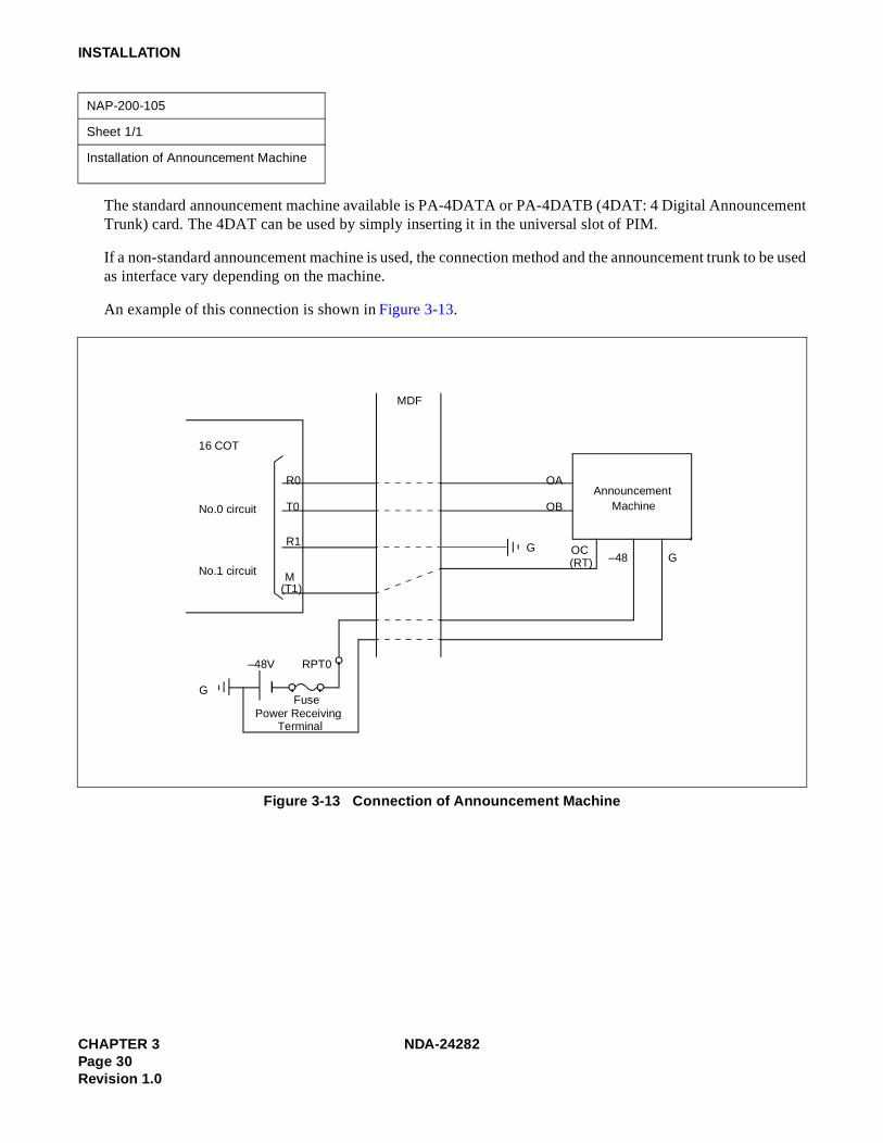
INSTALLATION
The standard announcement machine available is PA-4DATA or PA-4DATB (4DAT: 4 Digital AnnouncementTrunk) card. The 4DAT can be used by simply inserting it in the universal slot of PIM.
If a non-standard announcement machine is used, the connection method and the announcement trunk to be usedas interface vary depending on the machine.
An example of this connection is shown in Figure 3-13.
Figure 3-13 Connection of Announcement Machine
NAP-200-105
Sheet 1/1
Installation of Announcement Machine
Announcement Machine
FusePower Receiving
Terminal
G
–48V RPT0
16 COT
No.0 circuit
No.1 circuit
R0
T0
M (T1)
MDF
OA
OB
OC (RT) –48 G
R1 G
CHAPTER 3 NDA-24282Page 30Revision 1.0

INSTALLATION
Figure 3-14 shows the system configuration when IVR/Host is installed.For more details of IVR cable connection, refer to Figure 3-15 and for the Host connection, refer to Figure 3-16.
Figure 3-14 System Configuration (when IVR/Host is installed)
NAP-200-106
Sheet 1/1
Installation of IVR/Host
Note: When the client MIS and IVR/Host are installed in a system together, LAN network directly connectedwith these terminals should be separated by the router.
Router
MIS
IVR/Host
Dterm
(ACD Positions)
ELC
LC
HUB
PBX
LAN
LAN
Note
NDA-24282 CHAPTER 3Page 31
Revision 1.0

INSTALLATION
Figure 3-15 shows the cable connection between Host and the PBX.
Figure 3-15 Connection of Host
Note: When the client MIS and IVR/Host are installed in a system together, LAN network directly connectedwith these terminals should be separated by the router.
LANI
LANI
10BASE-T(Straight)
10BASE-T(Straight)
10BASE-T (Straight)
HUB PKG
PIM
LPM
BASEU
CHAPTER 3 NDA-24282Page 32Revision 1.0

INSTALLATION
Figure 3-16 shows the cable connection between IVR and the PBX.
Figure 3-16 Connection of IVR
PIM
16LCA0
B0A1
B1
~
A15
B15
Note
L2
L1
L2
L1
IVRRosette
MDFInstallation cable
Note: Connector leads (A0, B0) may be connected differently.
NDA-24282 CHAPTER 3Page 33
Revision 1.0

INSTALLATION
4. SYSTEM START-UP PROCEDURE FOR ADDING ACD FEATURES
4.1 ACD SOFTWARE INSTALLATION
This section explains the installation procedure for adding the Built-in ACDP software to the PBX in on-lineoperation. For more detailed information about start-up procedures before the ACD application software install,see the “Installation Manual”.
[Operation Procedure]
a. Basic Operating Procedure
STEP 1 : By using MEM_HDD command, save all data to both HDDs.
STEP 2 : Insert the Built-in ACDP software FD into the HDD of the PBX.
Note 1: When ACD service is used in a Fusion Network and when “ACD Trunk in a FCCS Network” is used:Install the software into the node that accommodates the ACDP.When “AGENT ANYWHERE” is used:Install the software into one node only. In this case, the node with the most ACD agent positions is recom-mended to prevent network traffic congestion. The node that uses the ACDP is most recommended accord-ing to the service condition Item 3 described in “Agent Anywhere - ACD” in Chapter 5.
STEP 3 : Install the Configuration Software to all nodes. Note 2
Note 2: This software is used to define the CallCenterWorX-Enterprise (ACD) system capacity (50, 200, 500, 900,or 2000 Agent Positions).
STEP 4 : Initialize the system (perform IPL, DM loading).PROGRAM=“LOAD”SYSTEM DATA=“LOAD”
CHAPTER 3 NDA-24282Page 34Revision 1.0
INSTALLATION
b. When Installing ACD Trunk into Multiple Fusion Nodes (Software installation when the ACD trunk is in-stalled at Fusion Nodes.)
(1) At the node that uses the ACDP, the ACD software (Built-in ACDP software) and ACD Option Soft-ware installation is necessary.
(2) At the node that accommodates the ACD trunk, only ACD Option Software installation is necessary.Do not install the ACD software.
(3) Initialize the node that uses the ACDP after the software installation.
c. When Installing ACD Agent Position into Multiple Fusion Nodes (For PBX Software Series 7300 or later)
(1) At the node that uses the ACDP, the ACD software (Built-in ACDP software) and the basic ACDOption Software, installation is necessary.
(2) At the node that accommodates the ACD trunk, ACD agent position, the basic ACD Option ServiceSoftware must be installed.
(3) Initialize the node that uses the ACDP after the software installation.
d. When Installing ACDP into Multiple Fusion Nodes (For PBX Software Series 7400 or later)
(1) At the node that uses the ACDP, the ACD software (Built-in ACDP software) and ACD Option Soft-ware installation is necessary.
(2) At the node that accommodates the ACD trunk, only ACD Option Software installation is necessary.Do not install the ACD software.
(3) Initialize the node that uses the ACDP after the initialization of the other nodes (non-ACDP nodes).
NDA-24282 CHAPTER 3Page 35
Revision 1.0

INSTALLATION
4.2 BASIC DATA ASSIGNMENT FOR START-UP
STEP 1 : Change the system data written in DM.ASYD SYS1INDEX2 - b0=1 (ACDP mounted)INDEX31 - b0~b3: CM mounting capacity
Assign Normally “06”. Note 1INDEX79 - b6=0 (ACD service is effective) Note 1INDEX207 - b0=1 (ACDP in system0 is used)
b1: ACDP in system10/1=Not used/Used
INDEX241 - b2=1 (call event process) Note 1
Note 1: When the ACD service is activated via FCCS, this data must be set to all nodes providing ACD service (Notjust the node accommodating the ACDP).
STEP 2 : Assign the system data written in LDM as shown below.ASYDL SYS1INDEX512: FPC of the self-nodeINDEX513: 01 Hex (LDM usage)INDEX515~518 b0~b7: IP address (Hex) for PBX over external LAN Note 2INDEX519~522 b0~b7: Subnet Mask (Hex) for PBX over external LAN Note 2INDEX523~526 b0~b7: Default Gateway Address for External LAN(This data is required when the Host is connected via gateway) Note 2INDEX864 - b0=1 (Built-in ACDP is provided)INDEX864 b1: Output the system message (4-R) when TCP-IP is normally disconnected.
0/1 = Effective/Ineffective Note 3b2: 0/1 = “Agent Anywhere” Out of Service/In Serviceb3: 0/1 = Multiple ACDPs Not Available/Available
INDEX865: FPC of Node Providing IP.INDEX866: FPC of Node Providing ACDP.
Note 2: If the MAT or SMDR has been connected with external LAN already, this data assignment is not necessary.
STEP 3 : Assign the System data written in NDM.This data is necessary when using “AGENT ANYWHERE” (Available since the PBX softwareSeries 7300.)ASYDN SYS1INDEX514- NDM usageINDEX533- FPC of the node that provides VNDM
STEP 4 : Check the station-to-station connection and confirm no fault status occurs or system messagesare output (such as cable connection fault, LCD display fault, memory alarm fault, abnormalinterrupt, etc.).
STEP 5 : Program the ACD office data. Also, program the Fusion data to make ACD service effectivethrough Fusion network, if necessary. Refer to Chapter 5, “Office Data Design”.
STEP 6 : Save the DM, ACD data memory into the HDD by using MEM_HDD.
CHAPTER 3 NDA-24282Page 36Revision 1.0

INSTALLATION
5. UPGRADING ACD SYSTEM FROM NEAX2400 ICS TO NEAX2400 IMX
Figure 3-17 and Table 3-1 show the requirements when upgrading the CallCenterWorX-Enerprise (ACD) sys-tem from NEAX2400 ICS to 2400 IMX.
5.1 HARDWARE AND SOFTWARE REQUIREMENTS
Figure 3-17 Hardware and Software Upgrading Requirements
(See Table 3-1.)
PBX
MAT
Router [9] Server MIS
DM
CPU
ACD DM
LAN
MIS DB
Client MIS
[3]
[1] [2]
[4]
[5]
[6]
[7]
[8]
ACDP
IVR/Host
[10]
Note 1: [5], [6], [7], [8] are not necessary for the ACD without MIS.
Note 2: [10] is not necessary for the ACD without IVR/Host.
NDA-24282 CHAPTER 3Page 37
Revision 1.0

INSTALLATION
Table 3-1 Hardware and Software Upgrading Requirements
No.Upgrading Hardware or
SoftwareNEAX2400 ICS
(before upgrading)NEAX2400 IMX
(after upgrading)
[1]
Generic Software• Basic software• Standard Service software• Optional software
All types of system PBX software Release 3 or later• Basic software (#1~#11)• Internal MAT software
(#1~#2)• TCP/IP software
[2]ACD software SC-2242 PRG-E or
SC-2243 PRG-FBuilt-in ACDP software
[3]MATHardware and Software
IBMPC/AT Windows
[4]ACD Data Memory PBX software Release 2 or
Release 3Built-in typeNecessary to be reprogrammed via [3]
[5], [6]Server MIS
Hardware and Software
Navigator MIS (IBMPC/AT) Navigator MIS (IBMPC/AT)For NEAX2400 IMX system
[7]Data base(Config., static data, etc.)
Navigator MIS (IBMPC/AT) Navigator MIS (IBMPC/AT)
[8]
Client MIS terminal Software Navigator MIS (IBMPC/AT) (a) Remote MIS terminal MIS terminal for Navigator MIS (IBMPC/AT)
(b) Client MIS terminal Navigator MIS client for NEAX2400 IMX system
[9] Router – Router
[10]
IVR/Host Hardware and Soft-ware
Note: Necessary when IVR/Host is added only.
CHAPTER 3 NDA-24282Page 38Revision 1.0

INSTALLATION
5.2 UPGRADING PROCEDURE
STEP 1 : Print out the existent data in the MIS terminal or save the data as the text file. Note 4
STEP 2 : List up the office data related to the current ACDP.
STEP 3 : Shutdown MIS operation following the appropriate procedure. Note 4
STEP 4 : Make busy the CPU (ACDP) card (CP53/CP54) and disconnect all cables connected to cardsrelated to ACD.
STEP 5 : Upgrade the PBX hardware following the Upgrade Manual for the PBX.
STEP 6 : Install the software below to upgrade the PBX software. Refer to Chapter 3, Section 4.1, “ACDSoftware Installation”.• An assortment of software for NEAX2400 IMX
• Built-in ACDP software Note 1
• System Configuration Software containing ACD Options Note 2
STEP 7 : Program the following ACD commands data again.ACDTN/ACDSPL/ACDLOG/ACDPSN/ACDCCV/ACDPLT/ACDTG/ACDANA/ACDIVR/ACDHS/ACDHC/ACDWS
STEP 8 : Start up the Navigator MIS for IBMPC/AT. Note 3
• Standard MIS hardware and software• MIS terminal hardware and software
STEP 9 : Start up the IVR/Host. Note 4
• IVR/Host hardware and software
• Related Equipment for LAN
STEP 10 : Perform the installation test.
Note 1: When ACD service is used in a Fusion Network, and when “ACD Trunk in aFusion Network” is used:Install the software into the node that accommodates the ACDP.When “AGENT ANYWHERE” is used:Install the software into one node only. In this case, the node with the most ACD agent positions isrecommended to prevent network traffic congestion. The node that uses the ACDP is most recommendedaccording to the service condition Item 3 described in “Agent Anywhere - ACD” in Chapter 5.
Note 2: When ACD features are activated in Fusion network, this software is installed in all nodes.
Note 3: This procedure is not necessary for the ACD without MIS.
Note 4: Details for start-up procedure are decided by the IVR/Host feature specifications.This procedure is not necessary when IVR/Host is not used.
NDA-24282 CHAPTER 3Page 39
Revision 1.0

This page is for your notes.
CHAPTER 3 NDA-24282Page 40Revision 1.0

CHAPTER 4 SWITCH SETTING OF ACD CIRCUIT CARDS
1. GENERAL
This chapter explains the circuit cards related to the NEAX2400 CallCenterWorX-Enterprise (ACD) Systemwhich are shown in Table 4-1.
Table 4-1 List of ACD Circuit Cards
SYMBOL CIRCUIT CARDMOUNTING
MODULEREMARKS
CPU PA-CP53 PIMU For circuit card type
EAPI PH-PC22/PH-PC27 LPRJ-A
ALMC PA-AL16 APM For module type
APINT PH-PC21 LPRJ-A
COPY PA-PC56-A APM
CPU PA-CP54 APM
CRAM PA-ME34 APM
IOC PA-IO02-A APM
PBI PH-BS16 APM
SPGT PA-GT17 MISCME For MISCME type
ELC PA-16ELCDD PIMU Common
16ELC PA-16ELCH PIMU Common
16ELC PA-16ELCJ PIMU Common
4DAT PA-4DATA PIMU Common
DAT PA-4DATB PIMU Common
4DTL PA-4DTLA PIMU Common
ETHER PA-CC98 APM/PIMU Module/Package
MBB PA-GT16 APM Module
NDA-24282 CHAPTER 4Page 41
Revision 1.0

SWITCH SETTING OF ACD CIRCUIT CARDS
2. EXPLANATION OF ACD CIRCUIT CARDS
This section explains each of the ACD circuit cards regarding the following items.
1. Function
Explanations are given about the functional outline and the purpose of each circuit card.
2. Mounting Location/Condition
The mounting location of each circuit card is illustrated with the mounting module name, slot number, etc.Any conditions pertaining to mounting are also denoted.
3. Face Layout of Lamps, Switches, and Connectors
The locations of the lamps, switches, and connectors provided on each circuit card are illustrated by a facelayout.
4. Lamp Indications
Lamps equipped on each circuit card, their names, colors, and indication states are tabulated.
5. Switch Setting
Switches equipped on each circuit card, their names, switch numbers, setting and its meaning, standard set-ting, etc. are tabulated.
6. External Interface
If the lead outputs of the circuit card are provided by an LT connector, the relation between the mountingslots and the LT connector is illustrated by an LT Connector Lead Face Layout. Also, if the lead outputs areprovided by other than an LT connector or the lead outputs are provided by the circuit card front connector,the connector lead accommodations and the connecting routes are illustrated.
A SWITCH SETTING SHEET showing module name, slot number, switch name, switch shape, etc. is providedat the end of the explanation of each circuit card.
CHAPTER 4 NDA-24282Page 42Revision 1.0

PA-CP53 (CPU)
PA-CP53 (CPU)
1. Function
This circuit card is the CPU card (Central Processing Unit) which controls the ACD Circuit Card Type Sys-tem. Using V60 microprocessor (32 bits), this CPU card provides programs and data memory. The card isequipped with EPROM of 2MB and SRAM of 1MB, respectively.
GATE
I/O LOCAL BUS
RS-232C (Non-protocol)
ACD-MISEAPI
CPU
ACDP
LPRJ-A
ACD in IMX system (Circuit Card Type)
Position within the system
SYSTEM
NDA-24282 CHAPTER 4Page 43
Revision 1.0
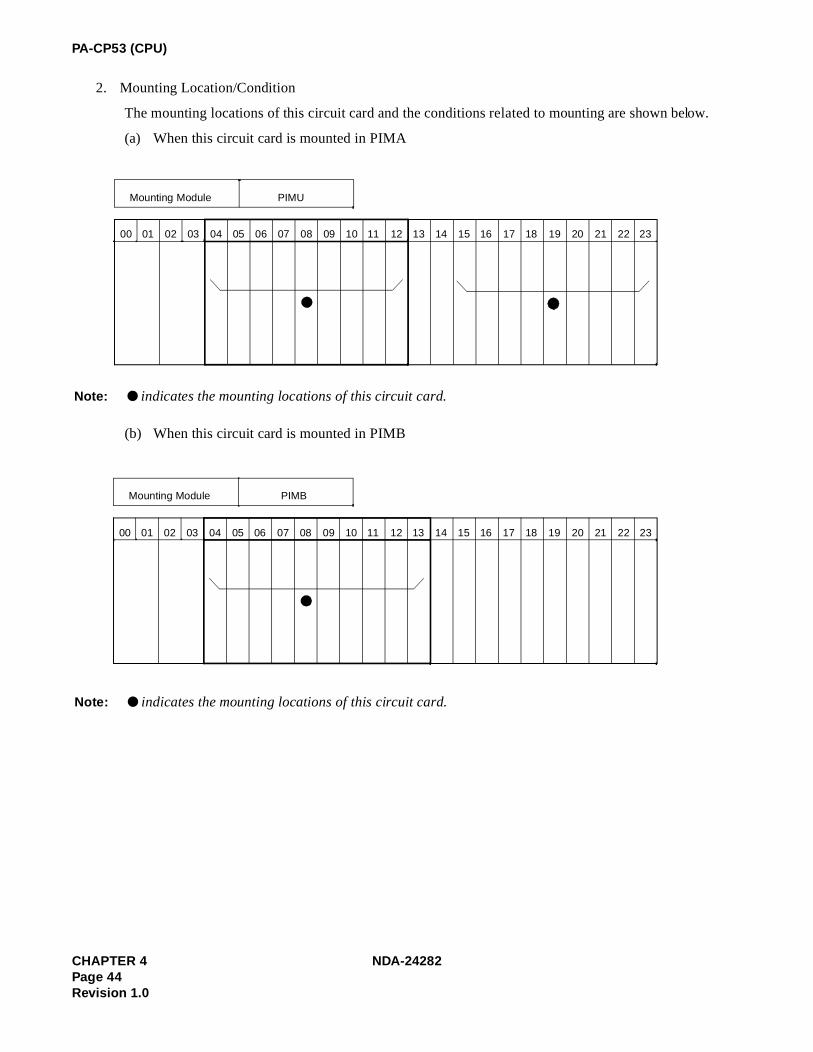
PA-CP53 (CPU)
2. Mounting Location/Condition
The mounting locations of this circuit card and the conditions related to mounting are shown below.
(a) When this circuit card is mounted in PIMA
(b) When this circuit card is mounted in PIMB
00 01 02 03 04 05 06 07 08 09 10 11 12 13 14 15 16 17 18 19 20 21 22 23
Mounting Module PIMU
Note: ● indicates the mounting locations of this circuit card.
00 01 02 03 04 05 06 07 08 09 10 11 12 13 14 15 16 17 18 19 20 21 22 23
Mounting Module PIMB
Note: ● indicates the mounting locations of this circuit card.
CHAPTER 4 NDA-24282Page 44Revision 1.0

PA-CP53 (CPU)
3. Face Layout of Lamps, Switches, and Connectors
The face layout of lamps, switches, and connectors of this circuit card is shown below.
4. Lamp Indications
The contents of lamp indications of this circuit card are shown in the table below.
Note: When this circuit is used only as ACDP, PA-CC98 card is not used and thus this card is operating normallyeven if this lamp is lighting.
LAMP NAME COLOR STATE
CPU OPE Green Remains lit while this circuit card is operating.
CLKA RedLights when a microprocessor operating clock failure has occurred in this circuit card.
COPA Red Lights when a C-level infinite loop has occurred.
LANA YellowLights when a major failure has occurred in PA-CC98 card or when this circuit card is not connected with PA-CC98 card. Note
DMWE Green Remains lit when the data memory in this circuit card is in write enable state.
CPU OPE
MBR
SW1 SW0 SW2
CLKA COPA LANA DMWE
RESET
SENSE
NDA-24282 CHAPTER 4Page 45
Revision 1.0

PA-CP53 (CPU)
5. Switch Settings
Standard settings of various switches on this circuit card are shown in the table below.
SWITCHNAME
SWITCHNO.
SETTINGSTANDARD
SETTINGMEANING
MBRUP Circuit card make busy request.
DOWN Circuit card make busy request cancel
RESET PUSH Starting of reset of this circuit card
SENSE
5 × On line (Normal Operation)
DClearing the data memory area at the time of initialization
SW0
1 OFF × Fixed
2 OFF × Fixed
3 OFF × Fixed
4 OFF × Fixed
5 OFF × Fixed
6 OFF × Fixed
7 OFF × Fixed
8 ON × Fixed
SW1
1 OFF × Fixed
2 OFF × Fixed
3 OFF × Fixed
4 OFF × Fixed
5 OFF × Fixed
6 ON × Fixed
7ON IMX
OFF ICS
8 OFF × Fixed
CHAPTER 4 NDA-24282Page 46Revision 1.0

PA-CP53 (CPU)
SW2
1ON × Internal NMI possible
OFF Internal NMI inhibited
2ON × Data Memory Write Protect cancel
OFF Data Memory Write Protect controllable
3ON Data Memory Write inhibited
OFF × Data Memory Write controllable
4ON When connecting PA-CC98 card
OFF When not connecting PA-CC98 card
5 OFF × Fixed
6 OFF × Fixed
7 OFF × Fixed
8 OFF × Fixed
SWITCHNAME
SWITCHNO.
SETTINGSTANDARD
SETTINGMEANING
NDA-24282 CHAPTER 4Page 47
Revision 1.0

PA-CP53 (CPU)
SWITCH SETTING SHEET
MODULE SLOT NO.SWITCH NAME
SWITCH SHAPE REMARKS
PIM any universal slot
MBR UP: Circuit card make busy request
DOWN: Circuit card make busy request cancel
RESET
SENSE
SW0
SW1 7 = ON for IMX7 = OFF for ICS
SW2 4 ON When connecting PA-CC98
ON
ON1 2 3 4 5 6 7 8
ON1 2 3 4 5 6 7 8
ON1 2 3 4 5 6 7 8
CHAPTER 4 NDA-24282Page 48Revision 1.0

PH-PC22 (EAPI)
PH-PC22 (EAPI)
1. Function
This circuit card is an I/O system functions integrated card to be used in the ACD Circuit Card Type System.This card supports the following functions.
(a) APINT Function: For processor communications between the CPU of the System and ACDP card,this circuit card provides FIFO for mutual I/O bus connections.
(b) IOC Function: For ACD-MIS connection, this circuit card provides a serial interface which conformswith RS-232C (two I/O ports).
2. Mounting Location/Condition
The mounting locations of this circuit card and the conditions related to mounting are shown below.
GATE
CPU
MEM
ECPY
GATE
CPU
MEM
MISC EAPI
ACDP
MISC
8-bit I/O Bus
RS-232C Extended 8-bit I/O Bus
TSW, INT
8-bit I/O Bus
32-bit MEM Bus
Position within the system
00 01 02 03 04 05 06 07 08 09 10 11 12 13 14 15 16 17 18 19 20 21 22 23
Mounting Module CMA
PH
PC
-22
PH
PC
-22
PH
PC
-22
Note
Note: This circuit card is mounted in any one of Slot No. 02~04.
NDA-24282 CHAPTER 4Page 49
Revision 1.0

PH-PC22 (EAPI)
3. Face Layout of Lamps, Switches, and Connectors
The face layout of lamps, switches, and connectors of this circuit card is shown below.
00 01 02 03 04
Mounting Module LPRJ-A
PH
PC
-22
PH
PC
-22
PH
PC
-22
Note
CPRAC-0 CPRAC-1
Note: This circuit card is mounted in any one of Slot No. 00~02
IOC OPE CLKALM
OPE/MB
MB
SW0 SW01
SW11
MBR
CHAPTER 4 NDA-24282Page 50Revision 1.0

PH-PC22 (EAPI)
4. Lamp Indications
The contents of lamp indications of this circuit card are shown in the table below.
5. Switch Settings
Standard settings of various switches on this circuit card are shown in the table below.
LAMP NAME COLOR STATE
OPE/MB Green Remains lit while this circuit card is operating.
IOCOPE Red Remains lit while the non-protocol/RS-232C Port Controller is operating normally.
CLKALM Red Lights when a clock failure has occurred.
SWITCH NAME
SWITCH NO. SETTINGSTANDARD
SETTINGMEANING
MBUP Circuit card make busy request
DOWN Circuit card make busy cancel
MBR
UPRequests the software to place the ACD-MIS Interface Port Controller into make-busy state.
DOWNCancels the request to place the ACD-MIS Interface Port Controller into make-busy state. (Circuit card operating state)
SW0
1 OFF ×
2 OFF ×
3 OFF ×
4 OFF ×
5 OFF ×
6 ON ×
7 OFF ×
8 ON ×
Fixed
NDA-24282 CHAPTER 4Page 51
Revision 1.0

PH-PC22 (EAPI)
SWITCH NAME
SWITCH NO. SETTINGSTANDARD
SETTINGMEANING
SW01 (for Port 0)
SW11 (for Port 1)(When using ACD-MIS
Interface Port)
1
2
3
4
ON ×Sets the non-protocol RS-232C port stop bit length to 1 bit.
OFFSets the non-protocol RS-232C port stop bit length to 2 bit.
5
ON ×Sets the non-protocol RS-232C port data length to 7 bit.
OFFSets the non-protocol RS-232C port data length to 8 bit.
6
7
8
ONSets the polarity of non-protocol RS-232C PB signal to Not Provided.
OFF ×Sets the polarity of non-protocol RS-232C PB signal to +, or sets PB signal to Provided.
SW01-1SW11-1
SW01-2SW11-2
SW01-3SW11-3
NON-PROTOCOL RS-232CPORT DATA SPEED SETTING
ON ON ON 300 bps
ON ON OFF 600 bps
ON OFF ON 1200 bps
ON OFF OFF 2400 bps
OFF ON ON 4800 bps
OFF ON OFF 9600 bps
OFF OFF ON 19200 bps
SW01-6SW11-6
SW01-7SW11-7
NON-PROTOCOL RS-232C PORTPARITY BIT SETTING
ON ON ODD Parity Check
ON OFF EVEN Parity Check (standard setting)
OFF OFF No Parity Check is to be made
CHAPTER 4 NDA-24282Page 52Revision 1.0

PH-PC22 (EAPI)
SWITCH SETTING SHEET
MODULE SLOT NO.SWITCH NAME
SWITCH SHAPE REMARKS
LCMA 020304
MB UP: Circuit card make busy
MBR DOWN: Circuit card make idle
LPRJ-A 000102
SW0
SW01 9600 bps Port 0, 1 Stop 7 Even
SW11 9600 bps Port 1, 1 Stop 7 Even
DOWN
DOWN
ON 1 2 3 4 5 6 7 8
ON 1 2 3 4 5 6 7 8
ON 1 2 3 4 5 6 7 8
NDA-24282 CHAPTER 4Page 53
Revision 1.0

PH-PC27 (EAPI)
PH-PC27 (EAPI)
1. Function
This circuit card is an I/O system functions integrated card to be used in the ACD Circuit Card Type System.This card supports the following functions.
(a) APINT Function: For processor communications between the CPU of the System and ACDP card,this circuit card provides FIFO for mutual I/O bus connections.
(b) IOC Function: For ACD-MIS connection, this circuit card provides a serial interface which conformswith RS-232C (three I/O ports).
2. Mounting Location/Condition
The mounting locations of this circuit card and the conditions related to mounting are shown below.
GATE
CPU
MEM
ECPY
GATE
CPU
MEM
MISC EAPI
ACDP
MISC
8-bit I/O Bus
RS-232C Extended 8-bit I/O Bus
TSW, INT
8-bit I/O Bus
32-bit MEM Bus
Position within the system
00 01 02 03 04 05 06 07 08 09 10 11 12 13 14 15 16 17 18 19 20 21 22 23
Mounting Module LCMA
PH
-PC
27
PH
-PC
27
PH
-PC
27
NoteNote: This circuit card is mounted in any one of Slot No. 02~04.
CHAPTER 4 NDA-24282Page 54Revision 1.0

PH-PC27 (EAPI)
3. Face Layout of Lamps, Switches, and Connectors
The face layout of lamps, switches, and connectors of this circuit card is shown below.
00 01 02 03 04
Mounting Module LPRJ-A
PH
-PC
27
PH
-PC
27
PH
-PC
27
Note
CPRAC-0 CPRAC-1
Note: This circuit card is mounted in any one of Slot No. 00~02.
IOC OPE CLKALM
OPE/MB
MB
SW10
SW12
SW11
MBR
SW0to CP-53
to CP-53
AP-1
AP-0
NDA-24282 CHAPTER 4Page 55
Revision 1.0

PH-PC27 (EAPI)
4. Lamp Indications
The contents of lamp indications of this circuit card are shown in the table below.
5. Switch Settings
Standard settings of various switches on this circuit card are shown in the table below.
LAMP NAME COLOR STATE
OPE/MB Green Remains lit while this circuit card is operating.
IOCOPE Red Remains lit while the non-protocol/RS-232C Port Controller is operating normally.
CLKALM Red Lights when a clock failure has occurred.
Note: The PH-PC27 is a three port EAPI card.
SWITCH NAME
SWITCH NO. SETTINGSTANDARD
SETTINGMEANING
MBUP Circuit card make busy.
DOWN Circuit card make idle.
MBR
UPRequests the software to place the ACD-MIS Interface Port Controller into make-busy state.
DOWNCancels the request to place the ACD-MIS Interface Port Controller into make-busy state. (Circuit card operating state)
SW0
1 OFF ×
2 OFF ×
3 OFF ×
4 OFF ×
5 OFF ×
6 ON ×
7 OFF ×
8 ON ×
Fixed
CHAPTER 4 NDA-24282Page 56Revision 1.0

PH-PC27 (EAPI)
Note: Ports 0, 1 and 2 translate to MIS ports 1, 2 and 3.
SWITCH NAME
SWITCH NO. SETTINGSTANDARD
SETTINGMEANING
SW10 (for Port 0)
SW11(for Port 1)
SW12(for Port 2)
1
2
3
MIS PortInterface
4
ON ×Sets the non-protocol RS-232C port stop bit length to 1 bit.
OFFSets the non-protocol RS-232C port stop bit length to 2 bit.
5
ON ×Sets the non-protocol RS-232C port data length to 7 bit.
OFFSets the non-protocol RS-232C port data length to 8 bit.
6
7
8
ONSets the polarity of non-protocol RS-232C PB signal to Not Provided.
OFF ×Sets the polarity of non-protocol RS-232C PB signal to +, or sets PB signal to Provided.
SW01-1SW11-1
SW01-2SW11-2
SW01-3SW11-3
NON-PROTOCOL RS-232CPORT DATA SPEED SETTING
ON ON ON 300 bps
ON ON OFF 600 bps
ON OFF ON 1200 bps
ON OFF OFF 2400 bps
OFF ON ON 4800 bps
OFF ON OFF 9600 bps
OFF OFF ON 19200 bps
SW01-6SW11-6
SW01-7SW11-7
NON-PROTOCOL RS-232C PORTPARITY BIT SETTING
ON ON ODD Parity Check
ON OFF EVEN Parity Check (standard setting)
OFF OFF No Parity Check is to be made
NDA-24282 CHAPTER 4Page 57
Revision 1.0

PH-PC27 (EAPI)
SWITCH SETTING SHEET
MODULE SLOT NO.SWITCH NAME
SWITCH SHAPE REMARKS
LCMA 020304
MB UP: Circuit card make busy.
MBR DOWN: Circuit card make idle.
LPRJ-A 000102
SW0
SW10 2, 4, 5, 6 ON only
SW11 2, 4, 5, 6 ON only
SW12 2, 4, 5, 6 ON only
DOWN
DOWN
ON 1 2 3 4 5 6 7 8
ON 1 2 3 4 5 6 7 8
ON 1 2 3 4 5 6 7 8
ON 1 2 3 4 5 6 7 8
CHAPTER 4 NDA-24282Page 58Revision 1.0

PA-AL16 (ALMC)
PA-AL16 (ALMC)
1. Function
This circuit card collects fault information and manages a dual-configuration system of the ACD ModuleType System. The card displays the collected fault information on the TOPU. Besides, the card providesthe functions for data communication between two ACDPs in the dual system configuration.
2. Mounting Location/Condition
The mounting location of this circuit card and the condition related to mounting are shown below.
When ACDP is provided by single system configuration in the IMG (IMX), this circuit card is to bemounted in its mounting slot only when the APMA is installed externally.
CPU
APINT APINT
CPU CPU
COPY COPY
CRAM CRAM
IOC
ACD-MIS
ALMC
RS-232C (Non-protocol)
IMX ACD system (Module Type)
I/O LOCAL BUS
(ACDP) (ACDP)
APM-A\E
Position within the System
00 01 02 03 04 05 06 07 08 09 10 11 12 13 14 15 16 17 18 19 20 21 22 23
Mounting Module APM-A\E
PA
-AL16
NDA-24282 CHAPTER 4Page 59
Revision 1.0

PA-AL16 (ALMC)
3. Face layout of Lamps, Switches, and Connectors
The face layout of lamps, switches, and connectors of this circuit card is shown below.
MBR
SW1
EMA SUP
MG
SW5
SW4
SW6
SW0
SW2
(SW3)
CPUSEL
CHAPTER 4 NDA-24282Page 60Revision 1.0

PA-AL16 (ALMC)
4. Switch Settings
Standard settings of various switches on this circuit card are shown in the table below.
Note 1: For IMG (IMX) (ICS), IMGx, IMGxh
Note 7: For MMG (ICS), UMG (ICS), UMGx
SWITCH NAMESWITCH
NO.SETTING
STANDARDSETTING
MEANING
MB UP Circuit card make busy.
DOWN Circuit card make idle.
EMASUP UP × Fixed
DOWN
CPUSEL UP
MIDDLE For ACDP Dual System Configuration
DOWN For ACDP Single System Configuration
MG (SW3) 0 Single CPU System Note 1
9 Multi CPU System Note 2
SW0 1 OFF × Fixed
2 OFF × Fixed
3 OFF × Fixed
4 ON × Fixed
SW1 1 OFF × Fixed
2 ON × Fixed
3 OFF × Fixed
4 ON × Fixed
SWITCH NAMESWITCH
NO.SETTING
STANDARDSETTING
MEANING
SW2 1 OFF × Fixed
2 ON × Fixed
ON
ON
ON
ON1 2 3 4
ON1 2 3 4
1 2ON
NDA-24282 CHAPTER 4Page 61
Revision 1.0

PA-AL16 (ALMC)
SW4 1 OFF × Alarm Bus Fixed
2 OFF × Alarm Bus Fixed
3 OFF × Alarm Bus Fixed
4 OFF × Alarm Bus Fixed
SW5 1 ON × Fixed
2 OFF × Fixed
3 OFF × Fixed
4ON For ACDP Dual System Configuration
OFF For ACDP Single System Configuration
SW61 OFF ×
Alarm Bus Fixed
2 OFF ×Alarm Bus Fixed
SWITCH NAMESWITCH
NO.SETTING
STANDARDSETTING
MEANING
ON1 2 3 4
ON1 2 3 4
1 2ON
CHAPTER 4 NDA-24282Page 62Revision 1.0

PA-AL16 (ALMC)
SWITCH SETTING SHEET
MODULE SLOT NO.SWITCH NAME
SWITCH SHAPE REMARKS
APM 20 MB UP: Circuit card make busy
DOWN:Circuit card make idle
EMASUP
CPUSEL Middle = ACDP Dual SystemDown = ACDP Single System
MG (SW3) 0 = Single CPU Systems9 = Multi CPU Systems
SW0
SW1 2 and 4 ON (Fixed)
SW2
SW4 Alarm Bus
SW5 4 ON = Dual ACDP4 OFF = Single ACDP
SW6 Alarm Bus
ON
ON
ON
0
9
ON 1 2 3 4
ON 1 2 3 4
1 2ON
ON 1 2 3 4
ON 1 2 3 4
1 2ON
NDA-24282 CHAPTER 4Page 63
Revision 1.0

PH-PC21 (APINT)
PH-PC21 (APINT)
1. Function
This circuit card is an inter-processor interface card and is used only for the Module Type ACD.
The card provides FIFO for mutual I/O bus connections for processor communication between the systemCPU and the ACDP.
2. Mounting Location/Condition
The mounting location of this circuit card and the condition related to mounting are shown below.
GATE
CPU
MEM
ECPY
GATE
CPU
MEM
APINT APINT
ACD Module
8-bit I/O Bus
Extended 8-bit I/O BusTSW, INT
8-bit I/O Bus
32-bit MEM Bus
Position within the system
00 01 02 03 04
Mounting Module LPRJ-AP
H-P
C27
PH
-PC
27
PH
-PC
27
Note
CPRAC-0 CPRAC-1
Note: This circuit card is mounted in any one of Slot No. 00~02.
CHAPTER 4 NDA-24282Page 64Revision 1.0

PH-PC21 (APINT)
3. Face Layout of Lamps, Switches, and Connectors
The face layout of lamps, switches, and connectors of this circuit card is shown below.
4. Lamp Indications
The contents of lamp indications of this circuit card are shown in the table below.
5. Switch Settings
Standard settings of various switches on this circuit card are shown in the table below.
LAMP NAME COLOR STATE
OPE/MBGreen Remains lit while this circuit card is operating.
Red Lights while this circuit card is in make-busy state.
CLKALM Red Lights when a failure has occurred to clocks for I/O bus synchronization.
SWITCH NAME
SWITCH NO. SETTINGSTANDARD
SETTINGMEANING
MBUP Circuit card make busy.
DOWN Circuit card make idle.
CLKALMOPE/MB
MB
SW01
AP0
AP1
NDA-24282 CHAPTER 4Page 65
Revision 1.0

PH-PC21 (APINT)
SW0
1
ON
When using this circuit card in the ACDP of single-system configuration or when connecting this circuit card to No. 0 system of the ACDP of dual-system configuration.
OFFWhen connecting this circuit card to No. 1 system of the ACDP of dual-system configuration.
2 ON × Fixed
3
ONWhen the ACDP is provided by single-system configuration.
OFFWhen the ACDP is provided by dual-system configuration.
4 OFF × Fixed
5 OFF × Fixed
6 ON
7 OFF
8 ON
SWITCH NAME
SWITCH NO. SETTINGSTANDARD
SETTINGMEANING
SW0-6 SW0-7 SW0-8 DEFINITION OF SOFTWARE TYPE
ON ON OFFTo be used in ACD Module Type (Single-System Configuration)
OFF ON OFFTo be used in ACD Module Type (Dual-System Configuration)
Others Not used
CHAPTER 4 NDA-24282Page 66Revision 1.0

PH-PC21 (APINT)
SWITCH SETTING SHEET
MODULE SLOT NO.SWITCH NAME
SWITCH SHAPE REMARKS
LPRJ-A 000102
MB UP: Circuit card make busyDOWN: Circuit card make idle
SW0
ON
ON 1 2 3 4 5 6 7 8
NDA-24282 CHAPTER 4Page 67
Revision 1.0

PA-PC56-A (COPY)
PA-PC56-A (COPY)
1. Function
This circuit card provides the function to copy the contents of the RAM of both the standby (ST-Y) systemand the active (ACT) system so that the contents of the RAM of both system may be always coinciding witheach other.
2. Mounting Location/Condition
The mounting locations of this circuit card and the conditions related to mounting are shown below.
• This circuit card is not used when the ACDP is provided in a single-system configuration.
CPU CPU
COPY COPY
CRAM CRAM
IOC
APM
ALMC
RS-232C (Non-protocol)
Position within the system
(ACDP) (ACDP)
00 01 02 03 04 05 06 07 08 09 10 11 12 13 14 15 16 17 18 19 20 21 22 23
Mounting Module APM
PA
-PC
56-A
PA
-PC
56-A
For No.1 systemFor No.0 system
CHAPTER 4 NDA-24282Page 68Revision 1.0

PA-PC56-A (COPY)
3. Face Layout of Lamps, Switches, and Connectors
The face layout of lamps, switches, and connectors of this circuit card is shown below.
4. Lamp Indications
The contents of lamp indications of this circuit card are shown in the table below.
LAMP NAME COLOR STATE
OPE Green Remains lit while this circuit card is operating in ACT state.
COPY Green Remains lit while this circuit card is operating in COPY mode.
OPE
SREQ
SW0
MB
MBS1
COPY
MBS0
NDA-24282 CHAPTER 4Page 69
Revision 1.0

PA-PC56-A (COPY)
5. Switch Settings
Standard settings of various switches on this circuit card are shown in the table below.
SWITCH NAME
SWITCH NO. SETTINGSTANDARD
SETTINGMEANING
MBUP Circuit card make busy.
DOWN Circuit card make idle.
SREQUP Separate mode request.
DOWN Separate mode request cancel (Copy mode).
SW0
1
ONTo be set in the case of System No. 0.(To be mounted in Slot No. 08 of APMA.)
OFFTo be set in the case of System No. 1.(To be mounted in Slot No. 17 of APMA.)
2 OFF ×
3 OFF ×
4 OFF ×
5 ON ×
6 ON ×
7 ON ×
8 ON ×
Fixed
CHAPTER 4 NDA-24282Page 70Revision 1.0

PA-PC56-A (COPY)
SWITCH SETTING SHEET
MODULE SLOT NO.SWITCH NAME
SWITCH SHAPE REMARKS
APM-A\E 0817
MB UP: Circuit card make busyDOWN:Circuit card make idle
SREQ
SW0 1 ON = System No. 01 OFF = System No. 1
ON
ON
ON 1 2 3 4 5 6 7 8
NDA-24282 CHAPTER 4Page 71
Revision 1.0

PA-CP54 (CPU)
PA-CP54 (CPU)
1. Function
This circuit card is the CPU card (Central Processing Unit) which controls the ACD Module Type System.Using the V60 microprocessor (32 bits), this CPU card provides programs and working memory. The cardis equipped with EPROM of 2MB and SRAM of maximum 384KB respectively.
2. Mounting Location/Condition
The mounting locations of this circuit card and the conditions related to mounting are shown below.
CPU
APINT APINT
CPU CPU
COPY COPY
CRAM CRAM
IOC
ACD-MIS
ALMC
RS-232C (Non-protocol)
ACD in IMX system (Module Type) Position within the System
I/O LOCAL BUS
(ACDP) (ACDP)
APM
00 01 02 03 04 05 06 07 08 09 10 11 12 13 14 15 16 17 18 19 20 21 22 23
Mounting Module APM-A\E
PA
-CP
54
PA
-CP
54
For No.1 systemFor No.0 system
CHAPTER 4 NDA-24282Page 72Revision 1.0

PA-CP54 (CPU)
3. Face Layout of Lamp, Switches, and Connectors
The face layout of lamps, switches, and connectors of this circuit card is shown below.
4. Lamp Indications
The contents of lamp indications of this circuit card are shown in the table below.
LAMP NAME COLOR STATE
CPU OPE Green Remains lit while this circuit card is operating.
CLK ALM RedLights when a microprocessor operating clock failure has occurred in this circuit card.
COP ALM Red Lights when a C-level infinite loop has occurred.
CPU OPE
MBR
SW0
SW4
SW3
CLKALM COPALM
RESET
SENSE
SW1
SW2
NDA-24282 CHAPTER 4Page 73
Revision 1.0

PA-CP54 (CPU)
5. Switch Settings
Standard settings of various switches on this circuit card are shown in the table below.
SWITCH NAME
SWITCH NO. SETTINGSTANDARD
SETTINGMEANING
MBUP Circuit card make busy.
DOWN Circuit card make idle.
RESET PUSH Starting of reset of this circuit card.
SENSE
0
1For MMG (ICS), UMG (ICS), UMGx (Normal Setting).
2
3
4
5For IMG (IMX) (ICS), IMGx, IMGxh, IMGdxh(Normal Setting).
6
7
8
9
When connecting the ACD System to MMG (ICS), UMG (ICS), UMGx; and when the data memory of ACDP is to be cleared at the time of ACDP initialization. (CRAM Clear).
A
B
C
D
When connecting the ACD System to IMG (IMX) (ICS), IMGx, IMGxh, IMGdxh; and when the data memory of ACDP is to be cleared at the time of ACDP initialization. (CRAM Clear).
E
F
CHAPTER 4 NDA-24282Page 74Revision 1.0

PA-CP54 (CPU)
SW0
1ON × Memory Parity Alarm Inhibited.
OFF Memory Parity Alarm not inhibited.
2ON External NMI input inhibited.
OFF × External NMI input not inhibited.
3ON Memory Alarm NMI inhibited.
OFF × Memory Alarm NMI not inhibited.
4ON COPALM inhibited.
OFF × COPALM not inhibited.
5 OFF × Fixed.
6 OFF × Fixed.
7
ONWhen ACDP is provided by dual-system con-figuration.
OFFWhen ACDP is provided by single-system con-figuration.
8 OFF × Fixed.
SW1
1
ONSets Ready Alarm Detect Timing to longer than 48 sec.
OFF × Sets Ready Alarm Detect Timing to longer than 6 sec.
2
ON Sets the interval of C-Level interrupt to 4 msec.
OFF × Sets the interval of C-Level interrupt to 16 msec.
3
ONNMI input from an external memory system is inhibited.
OFF × NMI input from an external memory system is not inhibited.
4 OFF × Fixed.
5ON × Equipped with 1.5 MB CRAM area.
OFF Equipped with 3 MB CRAM area.
6 ON × Fixed.
7ON IMX Fixed.
OFF ICS Fixed.
8ON × CRAM (PA-ME34) mounted.
OFF CRAM (PA-ME34) not mounted.
SWITCH NAME
SWITCH NO. SETTINGSTANDARD
SETTINGMEANING
NDA-24282 CHAPTER 4Page 75
Revision 1.0

PA-CP54 (CPU)
SW2
1
2
3ON × When equipping 1M bit SRAM IC.
OFF When equipping 256 K bit SRAM IC.
4
5
6
ON × When providing EE0000H ~ EFFFFFH and E00000H ~ E3FFFFH as RAM areas.
OFFWhen providing EE0000H ~ EFFFFFH as RAM area.
7
ON × When equipping 256 kbit SRAM IC as parity RAM.
OFFWhen equipping 64 kbit SRAM IC as parity RAM.
8ON Test mode (Always mis-hit state).
OFF × Normal operation mode.
SW3
1 OFF × Fixed.
2
ONWhen equipping 64 kbit SRAM IC as parity RAM.
OFF × When equipping 256 kbit SRAM IC as parity RAM.
3ON × When equipping EPROM IC of either 1M bit
2M bit.
OFF When equipping EPROM IC of 4M bit.
4
ON × When equipping EPROM IC of either 1M bit 2M bit as parity ROM.
OFFWhen equipping EPROM IC of 4M bit as pari-ty ROM.
SWITCH NAME
SWITCH NO. SETTINGSTANDARD
SETTINGMEANING
SW2-1 SW2-2 SETTING OF EPROM
ON ON When equipping 1M bit EPROM IC.
ON OFF When equipping 2M bit EPROM IC (standard).
OFF ON When equipping 4M bit EPROM IC.
OFF OFF Not used
SW2-4 SW2-5 SETTING OF ROM AREAS
ON ON When providing 1MB of F00000H ~ FFFFFFH.
OFF ONWhen providing 2MB of F00000H ~ FFFFFFH and 00000H ~ 0FFFFFH (standard setting).
OFF OFFWhen providing 4MB of F00000H ~ FFFFFFH and 00000H ~ 2FFFFFH.
CHAPTER 4 NDA-24282Page 76Revision 1.0

PA-CP54 (CPU)
SW4
1 OFF × Fixed
2 OFF × Fixed
3 ON × Fixed
4 OFF × Fixed
5 ON × Fixed
6 OFF × Fixed
7 OFF × Fixed
8 OFF × Fixed
SWITCH NAME
SWITCH NO. SETTINGSTANDARD
SETTINGMEANING
NDA-24282 CHAPTER 4Page 77
Revision 1.0

PA-CP54 (CPU)
SWITCH SETTING SHEET
MODULE SLOT NO. SWITCH NAME SWITCH SHAPE REMARKS
APM 0916
MBR UP: Circuit card make busy.DOWN:Circuit card make idle.
RESET
SENSE
SW0 7 ON = Dual ACDP7 OFF = Single ACDP
SW1 7 ON = IMX Systems8 ON = PA-ME34 Mounted8 OFF = PA-ME34 Not Mounted
SW2 Standard
SW3 Standard
SW4 Fixed
ON
ON 1 2 3 4 5 6 7 8
ON 1 2 3 4 5 6 7 8
ON 1 2 3 4 5 6 7 8
ON 1 2 3 4
ON 1 2 3 4 5 6 7 8
CHAPTER 4 NDA-24282Page 78Revision 1.0

PA-ME34 (CRAM)
PA-ME34 (CRAM)
1. Function
This circuit card is a RAM card for the ACD System and has memory capacity of 1.5 Mbytes.
2. Mounting Location/Condition
The mounting locations of this circuit card and the conditions related to mounting are shown below.
CPU CPU
COPY COPY
CRAM CRAM
IOC
APM-A\E
ALMC
RS-232C (Non-protocol)
Position within the system
(ACDP) (ACDP)
00 01 02 03 04 05 06 07 08 09 10 11 12 13 14 15 16 17 18 19 20 21 22 23
Mounting Module APM-A\EP
A-M
E34
PA
-ME
34
PA
-ME
34
For No. 1 systemFor No. 0 system
Note
Note: When ACDP is single system configuration, this circuit card is mounted in Slot No. 08.
NDA-24282 CHAPTER 4Page 79
Revision 1.0

PA-ME34 (CRAM)
3. Face Layout of Lamps, Switches, and Connectors
The face layout of lamps, switches, and connectors of this circuit card is shown below.
4. Lamp Indications
The contents of lamp indications of this circuit card are shown in the table below.
LAMP NAME COLOR STATE
OPE Green Lights when the CPU has accessed to the RAM in this card.
DMWE Red Lights when the data memory area of this card is in write enable state.
DMWD RedLights when the data memory area of this card is in write inhibited state as set by the DMWDK switch.
OPE
SW0
DMWE DMWD
DMWDK
PZ-ME17
SW1
CHAPTER 4 NDA-24282Page 80Revision 1.0

PA-ME34 (CRAM)
5. Switch Settings
Standard settings of various switches on this circuit card are shown in the table below.
SWITCH NAME
SWITCH NO. SETTINGSTANDARD
SETTINGMEANING
DMWDK UP Data memory area write inhibited
DOWN Data memory area write enable
SW0
1 OFF ×
2 OFF ×
3 ON ×
4 ON ×
5 OFF ×
6 ON ×
7 OFF × Fixed
8 OFF × Fixed
SW1
1
2
FixedSets the RAM area to $800000 ~ 8FFFFFH,$C00000 ~ C7FFFFH
SW1-1 SW1-2
ON ON Write Protect is provided.
OFF OFF Write Protect is not provided (Fixed).
NDA-24282 CHAPTER 4Page 81
Revision 1.0

PA-ME34 (CRAM)
SWITCH SETTING SHEET
MODULE SLOT NO.SWITCH NAME
SWITCH SHAPE REMARKS
APM-A\E 060819
DMWDK
SW0
SW1
ON
ON 1 2 3 4 5 6 7 8
ON 1 2
CHAPTER 4 NDA-24282Page 82Revision 1.0

PA-IO02-A (IOC)
PA-IO02-A (IOC)
1. Function
This circuit card is an I/O card (input/output control card) and provides a serial interface function by whichthe CPU performs mutual communications with the ACD-MIS conforming with the RS-232C Interface.
2. Mounting Location/Condition
The mounting locations of this circuit card and the conditions related to mounting are shown below.
CPU CPU
COPY COPY
CRAM CRAM
IOC
APM-A\E
ALMC
RS-232C (Non-protocol)
Position within the system
(ACDP) (ACDP)
00 01 02 03 04 05 06 07 08 09 10 11 12 13 14 15 16 17 18 19 20 21 22 23
Mounting Module APM-A\E
PA
-IO02-A
PA
-IO02-A
PA
-IO02-A
NDA-24282 CHAPTER 4Page 83
Revision 1.0

PA-IO02-A (IOC)
3. Face Layout of Lamps, Switches, and Connectors
The face layout of lamps, switches, and connectors of this circuit card is shown below.
4. Lamp Indications
The contents of lamp indications of this circuit card are shown in the table below.
LAMP NAME COLOR STATE
OPE Green Remains lit while this circuit card is operating in ACT mode.
ON LINE1 Green Remains lit while PORT 1 is in on-line state.
ON LINE0 Green Remains lit while PORT 0 is in on-line state.
OPE
MB
SW3ON LINE1 ON LINE0
MB REQ
SW0
SW01 SW11
SW02
SW12
OFF LINE
CHAPTER 4 NDA-24282Page 84Revision 1.0

PA-IO02-A (IOC)
5. Switch Settings
Standard settings of various switches on this circuit card are shown in the table below.
SWITCH NAME
SWITCH NO. SETTINGSTANDARD
SETTINGMEANING
MB UP Circuit card make busy.
DOWN Circuit card make idle.
MB REQ UP Circuit card make busy.
DOWN Circuit card make idle.
OFF LINE UP Setting is inhibited.
MIDDLE × Fixed.
DOWN Setting is inhibited.
SW01
2
3 OFF ×
4 OFF ×
5 OFF ×
6 OFF ×
7 OFF ×
8 OFF ×
SW3 1 OFF ×
2 OFF ×
3 OFF ×
4 OFF ×
SW0-1 SW0-2 SETTING OF IOC EQUIPMENT NUMBER
OFF OFF Sets IOC Equipment Number 0.
OFF ON Sets IOC Equipment Number 1.
ON OFF Sets IOC Equipment Number 2.
Fixed
Fixed
NDA-24282 CHAPTER 4Page 85
Revision 1.0

PA-IO02-A (IOC)
SW1 (for Port 0)SW11(for Port 1)
1
2
3
4
5
6ON × Data Length: 7 bits
OFF Data Length: 8 bits
7ON × Stop Bit: 1 bits
OFF Stop Bit: 2 bits
8
ONData store into the send-side buffer of the port is disabled.
OFF × Data of max. 64 kbytes are to be stored into the send-side buffer of the port.
SWITCH NAME
SWITCH NO. SETTINGSTANDARD
SETTINGMEANING
SW01-1SW11-1
SW01-2SW11-2
SW01-3SW11-3
DATA TRANSMISSION SPEED (BPS) SETTING
ON ON ON 300 bps
ON ON OFF 600 bps
ON OFF ON 1200 bps
ON OFF OFF 2400 bps
OFF ON ON 4800 bps
OFF ON OFF 9600 bps
SW01-4SW11-4
SW01-5SW11-5
PARITY SETTING
ON ON ODD Parity
ON OFF EVEN Parity (standard setting)
OFF OFF No Parity
CHAPTER 4 NDA-24282Page 86Revision 1.0

PA-IO02-A (IOC)
Note: When setting SW02-7/SW12-7 to ON, set SW02-1/SW12-1 to ON, also.
SW02 (for Port 0)SW12 (for Port 1)
1
ON × PB terminal becomes minus (-) when the port terminal is busy.
OFFPB terminal becomes plus (+) when the port terminal is busy.
2
ON × Sets the ER terminal of the port to Always ON.
OFFControls ON/OFF of the ER terminal of the port by the CPU.
3ON DR signal lead is not to be used to the port.
OFF × DR signal lead is to be used to the port.
4ON × CD signal lead is not to be used to the port.
OFF CD signal lead is to be used to the port.
5ON CS signal lead is not to be used to the port.
OFF × CS signal lead is to be used to the port.
6ON CI signal lead is not to be used to the port.
OFF × CI signal lead is to be used to the port.
7ON × PB signal lead is not to be used to the port. Note
OFF PB signal lead is to be used to the port.
8 OFF × Not used.
SWITCH NAME
SWITCH NO. SETTINGSTANDARD
SETTINGMEANING
NDA-24282 CHAPTER 4Page 87
Revision 1.0

PA-IO02-A (IOC)
6. External Interface
The RS connector leads accommodation of this circuit card is shown below.
Figure 4-1 RS Connector Leads Accommodation
26 27 28 29 30 31 32 33 34 35 36 37 38 39 40 41 42 43 44 45 46 47 48 49 50
00 01 02 03 04 05 06 07 08 09 10 11 12 13 14 15 16 17 18 19 20 21 22 23
RS0
APM-A\E
Slot No.
E E E E E CI0 E E E E E E E E E E E CI1 E E E E E E EXTA
1 2 3 4 5 6 7 8 9 10 11 12 13 14 15 16 17 18 19 20 21 22 23 24 25
PA
-IO02-A
RS Connector Leads Accommodation
RS0 Connector
SD0 RD0 RS0 CS0 DR0 SG0 CD0 ER0 PB0 SP00 SP10 SP20 SD1 RD1 RS1 CS1 DR1 SG1 CD1 ER1 PB1 SP01 SP11 SP21 EXTB
CHAPTER 4 NDA-24282Page 88Revision 1.0

PA-IO02-A (IOC)
SWITCH SETTING SHEET
MODULE SLOT NO.SWITCH NAME
SWITCH SHAPE REMARKS
APM-A\E 04 MB UP: Circuit card make busy.
MB REQ DOWN:Circuit card make idle.
OFF LINE
SW0
SW3
SW01
SW02
SW11
SW12
ON
ON
ON
ON 1 2 3 4 5 6 7 8
ON 1 2 3 4
ON 1 2 3 4 5 6 7 8
ON 1 2 3 4 5 6 7 8
ON 1 2 3 4 5 6 7 8
ON 1 2 3 4 5 6 7 8
NDA-24282 CHAPTER 4Page 89
Revision 1.0

PH-BS16 (PBI)
PH-BS16 (PBI)
1. Function
This circuit card provides an interface by which the ACDP performs inter-processor communications withanother Processor via the Processor Bus (P-BUS) under control of the ACDP (PA-CP54 card). Also, thiscircuit card is connected with the Maintenance Bus (M-BUS) and provides functions that allow the SP(System Processor) to read out status or fault information of the ACDP and that cause the ACDP to set make-busy or perform initialization.
2. Mounting Location/Condition
The mounting locations of this circuit card and the conditions related to mounting are shown below.
CPU (ACDP)
PBISP0
SPC
SP1
SPC
MEM
M-BUS No.0
M-BUS No.1
P-BUS No.0
P-BUS No.1
To other processor
To other processor
Position within the system
00 01 02 03 04 05 06 07 08 09 10 11 12 13 14 15 16 17 18 19 20 21 22 23
Mounting Module APM-A\E
PH
-BS
16
PH
-BS
16
For No. 1 systemFor No. 0 system
CHAPTER 4 NDA-24282Page 90Revision 1.0

PH-BS16 (PBI)
3. Face Layout of Lamps, Switches, and Connectors
The face layout of lamps, switches, and connectors of this circuit card is shown below.
OPE
MB
PWRALM
ACT
EQBY
PBIH
PBIL
B-OPE0
B-OPE1TR BSY RV BSY M-OPE
NDA-24282 CHAPTER 4Page 91
Revision 1.0

PH-BS16 (PBI)
4. Lamp Indications
The contents of lamp indications of this circuit card are shown in the table below.
LAMP NAME COLOR STATE
ACTGreen Remains lit while the CPU which controls this circuit card is in ACT state.
Red Lights with PBI Make Busy switch and MB switch turned on.
OPE Green Lights when the CPU has accessed to this circuit card.
PWRALM Red Lights when the On-Board Power Supply equipped on this circuit card is faulty.
EQBY Green Remains lit while the circuit card is in equipment busy state.
B-OPE0
Green Remains lit while BUS No. 0 of this circuit card is data transmitting and receiving.
RedLights when BUS No. 0 of this circuit card has been placed into make-busy state by SP or PBI Make Busy switch has been turned on.
B-OPE1
Green Remains lit while BUS No. 1 of this circuit card is data transmitting and receiving.
RedLights when BUS No. 1 of this circuit card has been placed into make-busy state by SP or PBI Make Busy switch has been turned on.
TRBSY Green Lights when the send memory of this circuit card is busy.
RVBSY Green Lights when the receive memory of this circuit card is busy.
M-OPE Green Lights when the data have been received from M-BUS.
CHAPTER 4 NDA-24282Page 92Revision 1.0

PH-BS16 (PBI)
5. Switch Settings
Standard settings of various switches on this circuit card are shown in the table below.
SWITCH NAMESWITCH
NO.SETTING
STAN-DARD
SETTINGMEANING
MB UP Circuit card make busy.
DOWN × Circuit card make idle.
PBIH 7 ×
Fixed
PBIL 0 Not used.
~
7 Not used
8ACDP0-System No. 0 (Mounted in Slot No. 13 of APMA0) (standard setting)
9ACDP0- System No. 1(Mounted in Slot No. 14 of APMA0) (standard setting)
AACDP1-System No. 0 (Mounted in Slot No. 13 of APMA1)
BACDP1-System No. 1 (Mounted in Slot No. 14 of APMA1)
CACDP2-System No. 0 (Mounted in Slot No. 13 of APMA2)
DACDP2-System No. 1 (Mounted in Slot No. 14 of APMA2)
E Not used
F Not used
ON
~
NDA-24282 CHAPTER 4Page 93
Revision 1.0

PH-BS16 (PBI)
SWITCH SETTING SHEET
MODULE SLOT NO.SWITCH NAME
SWITCH SHAPE REMARKS
1314
MB UP: Circuit card make busyDOWN:Circuit card make idle
PBIH 7: Fixed
PBIL
ON
7
CHAPTER 4 NDA-24282Page 94Revision 1.0

PA-GT17 (SPGT)
PA-GT17 (SPGT)
1. Function
This circuit card is used when the MISCME module is required. This circuit card provides flow control andterminates the extention of the MISC bus. This circuit card also controls the alarm LEDs equipped in theTop Unit.
Figure 4-2 Position in IMGdxh
Single Configuration
IMG0 LOCAL I/O BUS
TSW
GTGTA
GTA
GTA
To IMG 1
To IMG 2
To IMG 3
EXGT
EMA
IOC
MISC BUS
CPRB-A
HDD
FDD
APINT
APINT
APINT
APINT
MISCME
SPGT
INT
IMG0LOCAL I/O
TSW
GT0GTA0
GTA
GTA
To IMG 1
To IMG 2
To IMG 3
EXGT0
CPRB-A
HDD#0
FDD#0
APINT
APINT
APINT
APINT
MISCME
SPGT
INT0
Dual Configuration
GT1 GTA1
GTA
GTA
EXGT1
CPRB-A
HDD 1
FDD 1
INT1
EMA
IOC
To IMG 1
To IMG 2
To IMG 3
BUS
SPGT
MISC BUS MISC BUS
NDA-24282 CHAPTER 4Page 95
Revision 1.0

PA-GT17 (SPGT)
2. Mounting Location/Conditions
The SPGT card mounts in the MISCME as shown below.
3. Face Layout of Lamps, Switches, and Connectors
The face layout of lamps, switches, and connectors of this circuit card is shown below.
00 01 02 03 04 05 06 07 08 09 10 11 12 13 14 15 16 17 18 19 20 21 22 23
Mounting Module MISCMES
PG
T
SP
GT
SW10
OPE
MB
CLK ALM
DSPP
ALM
CHAPTER 4 NDA-24282Page 96Revision 1.0

PA-GT17 (SPGT)
4. Lamp Indications
The contents of lamp indications of this circuit card are shown in the table below.
5. Switch Setting
Standard settings of various switches on this circuit card are shown in the table below.
LAMP NAME COLOR STATE
OPE Green Remains lit while this circuit card is operating.
CLK ALM Red Lights when a clock down occurred.
SWITCH NAME
SWITCH NO.
SETTINGSTANDARD
SETTINGMEANING
MBON Circuit card make busy.
OFF × Circuit card make idle.
SW101 OFF × Fixed.
2 OFF × Fixed.
NDA-24282 CHAPTER 4Page 97
Revision 1.0

PA-GT17 (SPGT)
Switch Setting Sheet
MODULE SLOT NO.SWITCH NAME
SWITCH SHAPE REMARKS
MISCME 22 and 23
MB
UP: Circuit card make busyDOWN: Circuit card make idle
SW0
ON
ON 1 2
CHAPTER 4 NDA-24282Page 98Revision 1.0

PA-16ELCDD (ELC)
PA-16ELCDD (ELC)
1. Function
This circuit card is a line card which supports the interface of HDAC. When using voice only, 16 lines ofHDAC can be connected to this circuit card. Further, by changing the switch setting, this circuit card can beconnected with eight (8) lines respectively of voice terminals and data terminals.
NUMBER OF LINE
CIRCUITS
NUMBER OF TIME SLOTS
DATA COMMUNICATION FUNCTION REMARKS
8DLC Mode 8 circuits 16 Time Slots Available
16ELC Mode 16 circuits 16 Time Slots Not Available
C.O. LineCOTINT
T
S
W
CPU MEM
16chELC
(PA-16ELCDD)
Terminal 0
Terminal 7
Terminal 8
Terminal 15
Note
Position within the system
Note: To be accommodated to Terminals 0~7 in 8DLC Mode.
NDA-24282 CHAPTER 4Page 99
Revision 1.0

PA-16ELCDD (ELC)
2. Mounting Location/Condition
The mounting locations of this circuit card and the conditions related to mounting are shown below.
(a) When this circuit card is mounted in PIMA
(b) When this circuit card is mounted in PIMB
00 01 02 03 04 05 06 07 08 09 10 11 12 13 14 15 16 17 18 19 20 21 22 23
Mounting Module PIMU-A
00 01 02 03 04 05 06 07 08 09 10 11 12 13 14 15 16 17 18 19 20 21 22 23
Mounting Module PIMB
Note: ● indicates the mounting locations of this circuit card.
CHAPTER 4 NDA-24282Page 100Revision 1.0

PA-16ELCDD (ELC)
3. Face Layout of Lamps, Switches, and Connectors
The face layout of lamps, switches, and connectors of this circuit card is shown below.
4. Lamp Indications
The contents of lamp indications of this circuit card are shown in the table below.
LAMP NAME COLOR STATE
OPE Green Remains lit while this circuit card is in operating normally.
N-OPE Red Remains lit while this circuit card is isolated from the system.
PWRALM Red Lights when power supply to Dterm is abnormal on more than one circuit.
BL0
BL15
Green Lights when the corresponding circuit is busy.
FlashLights when the corresponding circuit is in make-busy state or when the related system data is not assigned.
MB
PWRALM
BLO
SW0
BL15
N-OPE
OPE
ELC Connector
NDA-24282 CHAPTER 4Page 101
Revision 1.0

PA-16ELCDD (ELC)
5. Switch Settings
Standard settings of various switches on this circuit card are shown in the table below.
SWITCH NAME
SWITCH NO. SETTINGSTANDARD
SETTINGMEANING
MBUP Circuit card make busy.
DOWN Circuit card make idle.
SW0
1ON For using this circuit card as 8DLC.
OFF For using this circuit card as 16ELC.
2 OFF ×
3 OFF ×
4 OFF ×
5 OFF ×
6 OFF ×
7
ONWhen connecting Dterm 24 key type to this circuit card (connection to any other type is not allowed).
OFF × When not connecting Dterm 24 key type to this circuit card.
8 OFF ×
Fixed
CHAPTER 4 NDA-24282Page 102Revision 1.0

PA-16ELCDD (ELC)
6. External Interface
The LT connector leads accommodation and the connection diagram of this circuit card are shown below.
(a) LT connector leads accommodation when this circuit card is mounted in PIMU-A
Figure 4-3 LT Connector Leads Accommodation of PIMU-A (1/2)
LT Connector Accommodation
26 27 28 29 30 31 32 33 34 35 36 37 38 39 40 41 42 43 44 45 46 47 48 49 50
00 01 02 03 04 05 06 07 08 09 10 11 12 13 14 15 16 17 18 19 20 21 22 23
LT0
* 2PIMA
LT Connector Name
Slot No.
LT1, 3, 5, 7, 9, 11 Connectors
Accommodated in *2
B00 B10 B01 B11 B02 B12 B03 B13 B04 B14 B05 B15 B06 B16 B07 B17
1 2 3 4 5 6 7 8 9 10 11 12 13 14 15 16 17 18 19 20 21 22 23 24 25
Group No.
LT1 LT2 LT3 LT4 LT5 LT6 LT7 LT8 LT9 LT10 LT11
01
00
03
02
05
04
07
06
09
08
11
10
01
00
03
02
05
04
07
06
09
08
11
10
15 14 13 12
19 18 17 16
23 22 21 20
15 14 13 12
19 18 17 16
23 22 21 20
* 1
Highway Block 0 1 2 6 7 83 4 5 9 10 11
26 27 28 29 30 31 32 33 34 35 36 37 38 39 40 41 42 43 44 45 46 47 48 49 50
LT0, 2, 4, 6, 8, 10 Connectors
Accommodated in *1
B00 B10 B01 B11 B02 B12 B03 B13 B04 B14 B05 B15 B06 B16 B07 B17
1 2 3 4 5 6 7 8 9 10 11 12 13 14 15 16 17 18 19 20 21 22 23 24 25
* 1
* 2
* 1
* 2
* 1
* 2
* 1
* 2
* 1
* 2
A00 A10 A01 A11 A02 A12 A03 A13 A04 A14 A05 A15 A06 A16 A07 A17
A00 A10 A01 A11 A02 A12 A03 A13 A04 A14 A05 A15 A06 A16 A07 A17
NDA-24282 CHAPTER 4Page 103
Revision 1.0

PA-16ELCDD (ELC)
Figure 4-3 LT Connector Leads Accommodation of PIMU-A (2/2)
LT Connector Accommodation
26 27 28 29 30 31 32 33 34 35 36 37 38 39 40 41 42 43 44 45 46 47 48 49 50
00 01 02 03 04 05 06 07 08 09 10 11 12 13 14 15 16 17 18 19 20 21 22 23
LT0
PIMA
LT Connector Name
Slot No.
LT1, 3, 5, 7, 9, 11 Connectors
B04 B14 B05 B15 B06 B16 B07 B17
1 2 3 4 5 6 7 8 9
10 11 12 13 14 15 16 17 18 19 20 21 22 23 24 25
Group No.
LT1 LT2 LT3 LT4 LT5 LT6 LT7 LT8 LT9 LT10 LT11
01
00
03
02
05
04
07
06
09
08
11
10
01
00
03
02
05
04
07
06
09
08
11
10
15 14 13 12
19 18 17 16
23 22 21 20
15 14 13 12
19 18 17 16
23 22 21 20
* 3
Highway Block 0 1 2 6 7 83 4 5 9 10 11
26 27 28 29 30 31 32 33 34 35 36 37 38 39 40 41 42 43 44 45 46 47 48 49 50
LT0, 2, 4, 6, 8, 10 Connectors
B00 B10 B01 B11 B02 B12 B03 B13
1 2 3 4 5 6 7 8 9 10 11 12 13 14 15 16 17 18 19 20 21 22 23 24 25
* 3
* 3
* 3
* 3
* 3
A00 A10 A01 A11 A02 A12 A03 A13
A04 A14 A05 A15 A06 A16 A07 A17
Accommodated in *3
CHAPTER 4 NDA-24282Page 104Revision 1.0

PA-16ELCDD (ELC)
(b) LT Connector Leads Accommodation when this circuit card is mounted in PIMB
Figure 4-4 LT Connector Leads Accommodation of PIMB (1/2)
LT Connector Accommodation
26 27 28 29 30 31 32 33 34 35 36 37 38 39 40 41 42 43 44 45 46 47 48 49 50
00 01 02 03 04 05 06 07 08 09 10 11 12 13 14 15 16 17 18 19 20 21 22 23
LT0
* 2PIMB
LT Connector Name
Slot No.
LT1, 3, 5, 8, 10, Connectors
Accommodated in *2
B00 B10 B01 B11 B02 B12 B03 B13 B04 B14 B05 B15 B06 B16 B07 B17
1 2 3 4 5 6 7 8 9 10 11 12 13 14 15 16 17 18 19 20 21 22 23 24 25
Group No.
LT1 LT2 LT3 LT4 LT5 LT6 LT7 LT8 LT9 LT10
03
02
01
00
07
06
05
04
11
10
09
08
15
14
13
12
19
18
17
16
23
22
21
20
15 14 13 12 11 10 09 08
23 22 21 20 19 18 17 16
07 06 05 04 03 02 01 00
15 14 13 12 11 10 09 08
23 22 21 20 19 18 17 16
* 1
Highway Block 0 1 2 3 4 5 6 7 8 10
26 27 28 29 30 31 32 33 34 35 36 37 38 39 40 41 42 43 44 45 46 47 48 49 50
LT0, 2, 4, 6, 7, 9 Connectors
Accommodated in *1
B00 B10 B01 B11 B02 B12 B03 B13 B04 B14 B05 B15 B06 B16 B07 B17 (B04) (B14) (B05) (B15) (B06) (B16) (B07) (B17)
1 2 3 4 5 6 7 8 9 10 11 12 13 14 15 16 17 18 19 20 21 22 23 24 25
* 1
* 2
* 1
* 2
* 1
* 2
* 1
* 2
A00 A10 A01 A11 A02 A12 A03 A13 A04 A14 A05 A15 A06 A16 A07 A17 (A04) (A14) (A05) (A15) (A06) (A16) (A07) (A17)
A00 A10 A01 A11 A02 A12 A03 A13 A04 A14 A05 A15 A06 A16 A07 A17
Note: Only LT6 outputs the signals shown in ( ).
* 1
0 2 4 6 8 10
9 11 1 3 5 7 9 11
03
02
01
00
07
06
05
04
07 06 05 04 03 02 01 00
15 14 13 12 11 10 09 08
23 22 21 20 19 18 17 16
NDA-24282 CHAPTER 4Page 105
Revision 1.0

PA-16ELCDD (ELC)
Figure 4-4 LT Connector Leads Accommodation of PIMB (2/2)
LT Connector Accommodation
26 27 28 29 30 31 32 33 34 35 36 37 38 39 40 41 42 43 44 45 46 47 48 49 50
PIMB
LT1, 3, 5, 8, 10 Connectors
B04 B14 B05 B15 B06 B16 B07 B17
1 2 3 4 5 6 7 8 9
10 11 12 13 14 15 16 17 18 19 20 21 22 23 24 25
* 3
Highway Block 0 1 2 3 4 5 6 7 8 10
26 27 28 29 30 31 32 33 34 35 36 37 38 39 40 41 42 43 44 45 46 47 48 49 50
LT0, 2, 4, 7, 9 Connectors
B00 B10 B01 B11 B02 B12 B03 B13
1 2 3 4 5 6 7 8 9 10 11 12 13 14 15 16 17 18 19 20 21 22 23 24 25
* 3
* 3
* 3
* 3
A00 A10 A01 A11 A02 A12 A03 A13
A04 A14 A05 A15 A06 A16 A07 A17
0 2 4 6 8 10
9 11 1 3 5 7 9 11
Accommodated in *3
00 01 02 03 04 05 06 07 08 09 10 11 12 13 14 15 16 17 18 19 20 21 22 23
LT0LT Connector Name
Slot No.
Group No.
LT1 LT2 LT3 LT4 LT5 LT6 LT7 LT8 LT9 LT10
03
02
01
00
07
06
05
04
11
10
09
08
15
14
13
12
19
18
17
16
23
22
21
20
15 14 13 12 11 10 09 08
23 22 21 20 19 18 17 16
07 06 05 04 03 02 01 00
15 14 13 12 11 10 09 08
23 22 21 20 19 18 17 16
03
02
01
00
07
06
05
04
07 06 05 04 03 02 01 00
15 14 13 12 11 10 09 08
23 22 21 20 19 18 17 16
CHAPTER 4 NDA-24282Page 106Revision 1.0

PA-16ELCDD (ELC)
(c) Front connector leads accommodation
Leads from No. 8~15 circuits come out to the front connector of the circuit card. The front connectorleads are shown below.
Figure 4-5 ELC Connector Leads Accommodation of PIMB (1/2)
ELC Connector Leads Accommodation
1A 2A 3A 4A 5A 6A 7A 8A 9A 10A 11A 12A 13A 14A 15A 16A 17A
Front Connector Leads
A08 A18 A09 A19 A0A A1A A0B A1B A0C A1C A0D A1D A0E A1E A0F A1F
26 27 28 29 30 31 32 33 34 35 36 37 38 39 40 41 42 43 44 45 46 47 48 49 50
CHAMP Connector Leads
B08 B18 B09 B19 B0A B1A B0B B1B B0C B1C B0D B1D B0E B1E B0F B1F
1 2 3 4 5 6 7 8 9
10 11 12 13 14 15 16 17 18 19 20 21 22 23 24 25
A08 A18 A09 A19 A0A A1A A0B A1B A0C A1C A0D A1D A0E A1E A0F A1F
1B 2B 3B 4B 5B 6B 7B 8B 9B 10B 11B 12B 13B 14B 15B 16B 17B
B08 B18 B09 B19 B0A B1A B0B B1B B0C B1C B0D B1D B0E B1E B0F B1F
No. 8
No. 9
No. 10
No. 11
No. 12
No. 13
No. 14
No. 15
When using 16
ELC CA-B cable
NDA-24282 CHAPTER 4Page 107
Revision 1.0
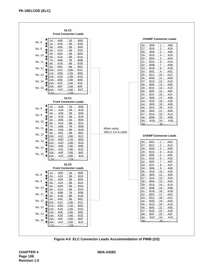
PA-16ELCDD (ELC)
Figure 4-5 ELC Connector Leads Accommodation of PIMB (2/2)
26 27 28 29 30 31 32 33 34 35 36 37 38 39 40 41 42 43 44 45 46 47 48 49 50
CHAMP Connector Leads
B08 B18 B09 B19 B0A B1A B0B B1B B0C B1C B0D B1D B0E B1E B0F B1F B08 B18 B09 B19 B0A B1A B0B B1B
1 2 3 4 5 6 7 8 9 10 11 12 13 14 15 16 17 18 19 20 21 22 23 24 25
A08 A18 A09 A19 A0A A1A A0B A1B A0C A1C A0D A1D A0E A1E A0F A1F A08 A18 A09 A19 A0A A1A A0B A1B
26 27 28 29 30 31 32 33 34 35 36 37 38 39 40 41 42 43 44 45 46 47 48 49 50
CHAMP Connector Leads
B0C B1C B0D B1D B0E B1E B0F B1F B08 B18 B09 B19 B0A B1A B0B B1B B0C B1C B0D B1D B0E B1E B0F B1F
1 2 3 4 5 6 7 8 9 10 11 12 13 14 15 16 17 18 19 20 21 22 23 24 25
When using 16ELC CA-A cable
A0C A1C A0D A1D A0E A1E A0F A1F A08 A18 A09 A19 A0A A1A A0B A1B A0C A1C A0D A1D A0E A1E A0F A1F
1A 2A 3A 4A 5A 6A 7A 8A 9A
10A 11A 12A 13A 14A 15A 16A 17A
ELC2 Front Connector Leads
A08 A18 A09 A19 A0A A1A A0B A1B A0C A1C A0D A1D A0E A1E A0F A1F
1B 2B 3B 4B 5B 6B 7B 8B 9B 10B 11B 12B 13B 14B 15B 16B 17B
B08 B18 B09 B19 B0A B1A B0B B1B B0C B1C B0D B1D B0E B1E B0F B1F
No. 8
No. 9
No. 10
No. 11
No. 12
No. 13
No. 14
No. 15
1A 2A 3A 4A 5A 6A 7A 8A 9A 10A 11A 12A 13A 14A 15A 16A 17A
ELC1 Front Connector Leads
A08 A18 A09 A19 A0A A1A A0B A1B A0C A1C A0D A1D A0E A1E A0F A1F
1B 2B 3B 4B 5B 6B 7B 8B 9B 10B 11B 12B 13B 14B 15B 16B 17B
B08 B18 B09 B19 B0A B1A B0B B1B B0C B1C B0D B1D B0E B1E B0F B1F
No. 8
No. 9
No. 10
No. 11
No. 12
No. 13
No. 14
No. 15
1A 2A 3A 4A 5A 6A 7A 8A 9A
10A 11A 12A 13A 14A 15A 16A 17A
ELC0 Front Connector Leads
A08 A18 A09 A19 A0A A1A A0B A1B A0C A1C A0D A1D A0E A1E A0F A1F
1B 2B 3B 4B 5B 6B 7B 8B 9B 10B 11B 12B 13B 14B 15B 16B 17B
B08 B18 B09 B19 B0A B1A B0B B1B B0C B1C B0D B1D B0E B1E B0F B1F
No. 8
No. 9
No. 10
No. 11
No. 12
No. 13
No. 14
No. 15
CHAPTER 4 NDA-24282Page 108Revision 1.0

PA-16ELCDD (ELC)
(d) Connection Diagram
Figure 4-6 Connection Diagram
NEAX2400 ICSMDF
ELC
Modular
Block
HDAC
A00
B00
A10
B10
A0
B0
A1
B1
A08
B08
A18
B18
A0
B0
A1
B1 Modular
Block
Front connector
HDAC
NDA-24282 CHAPTER 4Page 109
Revision 1.0

PA-16ELCDD (ELC)
SWITCH SETTING SHEET
MODULE SLOT NO.SWITCH NAME
SWITCH SHAPE REMARKS
PIMU-A 04~1215~23
MB UP: Circuit card make busy.DOWN:Circuit card make idle.
SW0
ON
ON 1 2 3 4 5 6 7 8
CHAPTER 4 NDA-24282Page 110Revision 1.0

PA-16ELCH (16ELC)
PA-16ELCH (16ELC)
1. Function
This circuit card is a line circuit card that supports the interface of 16 circuits or 8 circuits of a 2W-DigitalTerminal based on TCM transmission system (Time Compression Multiplex).
This circuit card can be used as an 8-circuit voice/data digital line (8DLC Mode) and a 16-circuit voice onlydigital line circuit (16ELC Mode), and can be connected to any Dterm of the Dterm Series III. Differences inoperations by mode are shown below.
NUMBER OF CIRCUITS
NUMBER OF TIME SLOTS
DATA COMMUNICATION FUNCTION REMARKS
8DLC Mode 8 circuits 16 Time Slots Provided
16ELC Mode 16 circuits 16 Time Slots Not Provided
Dterm0
Dterm7
Dterm8
Dterm 15
Note
16ELC
16ch
COT
MEMCPU
C.O. Line
Position within the System
INT
T
S
W
Note: If 8DLC mode, the circuit card isaccommodated to Dterm 0~7.
NDA-24282 CHAPTER 4Page 111
Revision 1.0

PA-16ELCH (16ELC)
2. Mounting Location/Condition
The mounting locations of this circuit card and the conditions related to mounting are shown below.
(a) When this circuit card is mounted in PIMA
(b) When this circuit card is mounted in PIMB
01 02 03 04 05 06 07 08 09 10 11 12 13 14 15 16 17 18 19 20 21 22 23
Mounting Module PIMU-A
00
Note: Indicates that the slots are a universal slot for line/trunk circuit cards.
Mounting Module PIMB
01 02 03 04 05 06 07 08 09 10 11 12 13 14 15 16 17 18 19 20 21 22 2300
Note: Indicates that the slots are a universal slot for line/trunk circuit cards.
CHAPTER 4 NDA-24282Page 112Revision 1.0

PA-16ELCH (16ELC)
3. Face Layout of Lamps, Switches, and Connectors
The face layout of lamps, switches, and connectors of this circuit card is shown below.
4. Lamp Indications
The contents of lamp indications of this circuit card are shown in the table below.
LAMP NAME COLOR STATE
OPEGreen Remains lit while on-line operations are normal.
OFF Off when on-line operations are abnormal.
PWR ALMRed Lights when more than one power supply circuit are abnormal.
OFF Off when all the power supply circuits are normal.
BL0 Green Lights when the corresponding circuit is busy.
~ FlashFlashes when the corresponding circuit is in make-busy state or the system data is not assigned.
BL15 OFF Off when the corresponding circuit is idle.
OPE
MB
PWR ALM
BL15
BL0
SW0
NDA-24282 CHAPTER 4Page 113
Revision 1.0

PA-16ELCH (16ELC)
5. Switch Settings
Standard settings of various switches on this circuit card are shown in the table below.
Note 1: APR-J/APA-J is an optional device to be connected to Dterm and provides interface for analog terminal.
Note 2: By setting SWO-1 and SWO-7 as explained in the above table, either APR-J/APA-J or Data Adapter can be used.
SWITCH NAME
SWITCH NO. SETTINGSTANDARD
SETTINGMEANING
SW0 1Note 1Note 2
ON When APR-J/APA-J is not connected.
OFF When APR-J/APA-J is connected.
2
ONSetting of Speech Level: NEAX2400 IMS (HDS) Level.
OFFSetting of Speech Level: NEAX2400 IMS (ICS) Level.
3ON × Fixed in the system.
OFF
4ON × Single Port Mode.
OFF Dual Port Mode.
5ON × Fixed in the system.
OFF
6ON × Fixed in the system.
OFF
7ON 16ELC Mode.
OFF 8DLC Mode.
8ON × Fixed in the system.
OFF
MB UP Circuit card make busy.
DOWN × Circuit card make idle.
CHAPTER 4 NDA-24282Page 114Revision 1.0

PA-16ELCH (16ELC)
SW0-7
SW0-7ON OFF
ON
Up to 16 circuits can be connected. Only voice is used.
Up to 8 circuits can be connected.Simultaneous communications of voice and data (use of Data Adapter) can be utilized.Make this setting when using Data Adapter.
OFF
Up to 16 circuits can be connected.Simultaneous communications of voice and data (use of APR-J/APA-J) cannot be serviced.When either data or voice is used by changing over with APR-J/APA-J.
Up to 8 circuits can be connected.Simultaneous communications of voice and data (use of APR-J/APA-J) can be serviced.
NDA-24282 CHAPTER 4Page 115
Revision 1.0

PA-16ELCH (16ELC)
6. External Interface
Accommodation of the LT connector leads of this circuit card and connecting route diagram are shown be-low.
(a) LT Connector Lead Accommodation when this circuit card is mounted in PIMA
• When the mode is 16ELC Mode/Single Port Mode.
Figure 4-7 LT Connector Leads Accommodation of PIMU-A (1 of 3)
LT Connector Accommodation
26 27 28 29 30 31 32 33 34 35 36 37 38 39 40 41 42 43 44 45 46 47 48 49 50
00 01 02 03 04 05 06 07 08 09 10 11 12 13 14 15 16 17 18 19 20 21 22 23
LT0
PIMA
LT Connector Name
Slot No.
LT1, 3, 5, 7, 9, 11 Connector
Accommodated in *2
B0 B1 B2 B3 B4 B5 B6 B7 B8 B9 B10 B11 B12 B13 B14 B15
1 2 3 4 5 6 7 8 9 10 11 12 13 14 15 16 17 18 19 20 21 22 23 24 25
A0 A1 A2 A3 A4 A5 A6 A7 A8 A9 A10 A11 A12 A13 A14 A15
Group No.
LT1 LT2 LT3 LT4 LT5 LT6 LT7 LT8 LT9 LT10 LT11
01
00
03
02
05
04
07
06
09
08
11
10
01
00
03
02
05
04
07
06
09
08
11
10
15 14 13 12
19 18 17 16
23 22 21 20
15 141312
19 18 17 16
23 22 21 20
* 1
Highway Block 0 1 2 6 7 83 4 5 9 10 11
26 272829 30 31 32 33 34 35 36 37 38 39 40 41 42 43 44 45 46 47 48 49 50
LT0, 2, 4, 6, 8, 10 Connector
Accommodated in *1
B0 B1 B2 B3 B4 B5 B6 B7 B8 B9 B10 B11 B12 B13 B14 B15
1 2 3 4 5 6 7 8 9
10 11 12 13 14 15 16 17 18 19 20 21 22 23 24 25
A0 A1 A2 A3 A4 A5 A6 A7 A8 A9 A10 A11 A12 A13 A14 A15
PW
R
* 1
* 1
* 1
* 1
* 1
* 2
* 2
* 2
* 2
* 2
* 2
PW
R
CHAPTER 4 NDA-24282Page 116Revision 1.0

PA-16ELCH (16ELC)
Figure 4-7 LT Connector Leads Accommodation of PIMU-A (2 of 3)
LT Connector Accommodation
26 27 28 29 30 31 32 33 34 35 36 37 38 39 40 41 42 43 44 45 46 47 48 49 50
00 01 02 03 04 05 06 07 08 09 10 11 12 13 14 15 16 17 18 19 20 21 22 23
LT0
PIMA
LT Connector Name
Slot No.
LT1, 3, 5, 7, 9, 11 Connector
B8 B9 B10 B11 B12 B13 B14B15
1 2 3 4 5 6 7 8 9 10 11 12 13 14 15 16 17 18 19 20 21 22 23 24 25
A8 A9 A10 A11 A12 A13 A14 A15
Group No.
LT1 LT2 LT3 LT4 LT5 LT6 LT7 LT8 LT9 LT10 LT11
01
00
03
02
05
04
07
06
09
08
11
10
01
00
03
02
05
04
07
06
09
08
11
10
15 14 13 12
19 18 17 16
23 22 21 20
15 14 13 12
19 18 17 16
23 22 21 20
* 3
Highway Block 0 1 2 6 7 83 4 5 9 10 11
26 27 28 29 30 31 32 33 34 35 36 37 38 39 40 41 42 43 44 45 46 47 48 49 50
LT0, 2, 4, 6, 8, 10 Connector
B0 B1 B2 B3 B4 B5 B6 B7
1 2 3 4 5 6 7 8 9 10 11 12 13 14 15 16 17 18 19 20 21 22 23 24 25
A0 A1 A2 A3 A4 A5 A6 A7
PW
R
Accommodated in *3
PW
R
* 3
* 3
* 3
* 3
* 3
NDA-24282 CHAPTER 4Page 117
Revision 1.0

PA-16ELCH (16ELC)
• When the mode is 8DLC Mode/Dual Port Mode.
Figure 4-7 LT Connector Leads Accommodation of PIMU-A (3 of 3)
LT Connector Accommodation
26 27 28 29 30 31 32 33 34 35 36 37 38 39 40 41 42 43 44 45 46 47 48 49 50
00 01 02 03 04 05 06 07 08 09 10 11 12 13 14 15 16 17 18 19 20 21 22 23
LT0
PW
RPIMA
LT Connector Name
Slot No.
LT1, 3, 5, 7, 9, 11 Connector
Accommodated in *2
1 2 3 4 5 6 7 8 9 10 11 12 13 14 15 16 17 18 19 20 21 22 23 24 25
Group No.
LT1 LT2 LT3 LT4 LT5 LT6 LT7 LT8 LT9 LT10 LT11
01
00
03
02
05
04
07
06
09
08
11
10
01
00
03
02
05
04
07
06
09
08
11
10
15 14 13 12
19 18 17 16
23 22 21 20
15 14 13 12
19 18 17 16
23 22 21 20
Highway Block 0 1 2 6 7 83 4 5 9 10 11
26 27 28 29 30 31 32 33 34 35 36 37 38 39 40 41 42 43 44 45 46 47 48 49 50
LT0, 2, 4, 6, 8, 10 Connector
Accommodated in *1
B0 B1 B2 B3 B4 B5 B6 B7
1 2 3 4 5 6 7 8 9 10 11 12 13 14 15 16 17 18 19 20 21 22 23 24 25
A0 A1 A2 A3 A4 A5 A6 A7
26 27 28 29 30 31 32 33 34 35 36 37 38 39 40 41 42 43 44 45 46 47 48 49 50
LT1, 3, 5, 7, 9, 11 Connector
Accommodated in *3
1 2 3 4 5 6 7 8 9
10 11 12 13 14 15 16 17 18 19 20 21 22 23 24 25
* 1
B0 B1 B2 B3 B4 B5 B6 B7
A0 A1 A2 A3 A4 A5 A6 A7
B0 B1 B2 B3 B4 B5 B6 B7
A0 A1 A2 A3 A4 A5 A6 A7
PW
R
* 1
* 1
* 1
* 1
* 1
* 2
* 2
* 2
* 2
* 2
* 2
* 3
* 3
* 3
* 3
* 3
* 3
CHAPTER 4 NDA-24282Page 118Revision 1.0

PA-16ELCH (16ELC)
(b) LT Connector Lead Accommodation when this circuit card is mounted in PIMB
• When the mode is 16ELC Mode and the APR-J/APA-J is used.
Figure 4-8 LT Connector Leads Accommodation of PIMB (1 of 3)
LT Connector Accommodation
26 27 28 29 30 31 32 33 34 35 36 37 38 39 40 41 42 43 44 45 46 47 48 49 50
LT1, 3, 5, 8, 10 Connector
1 2 3 4 5 6 7 8 9 10 11 12 13 14 15 16 17 18 19 20 21 22 23 24 25
26 27 28 29 30 31 32 33 34 35 36 37 38 39 40 41 42 43 44 45 46 47 48 49 50
LT0, 2, 4, 6, 7, 9 Connector
B0 B1 B2 B3 B4 B5 B6 B7 B8 B9 B10 B11 B12 B13 B14 B15
1 2 3 4 5 6 7 8 9
10 11 12 13 14 15 16 17 18 19 20 21 22 23 24 25
B0 B1 B2 B3 B4 B5 B6 B7 B8 B9 B10 B11 B12 B13 B14 B15
A0 A1 A2 A3 A4 A5 A6 A7 A8 A9 A10 A11 A12 A13 A14 A15
00 01 02 03 04 05 06 07 08 09 10 11 12 13 14 15 16 17 18 19 20 21 22 23
LT0
PIMB
LT Connector Name
Slot No.
Group No.
LT1 LT2 LT3 LT4 LT5 LT7 LT8 LT9 LT10
03
02
07
06
11
10
15
14
19
18
23
22
15 14 13 12
07 06 05 04
15 14 13 12
23 22 21 20
Highway Block 0 1 2 6 7 8
9
3 4 5 10
11
LT6
23 22 21 20
07 06 05 04
15 14 13 12
23 22 21 20
01
00
05
04
09
08
13
12
17
16
21
20
11 10 09 08
03 02 01 00
11 10 09 08
19 18 17 16
19 18 17 16
03 02 01 00
11 10 09 08
19 18 17 16
03
02
01
00
07
06
05
04
8
9
10
11
4
5
6
7
2
3
0
1
* 1
Accommodated in *1 Accommodation *2
A0 A1 A2 A3 A4 A5 A6 A7 A8 A9 A10 A11 A12 A13 A14 A15
* 1
* 1
* 1
* 1
* 1
* 2
* 2
* 2
* 2
* 2
NDA-24282 CHAPTER 4Page 119
Revision 1.0

PA-16ELCH (16ELC)
Figure 4-8 LT Connector Leads Accommodation of PIMB (2 of 3)
LT Connector Accommodation
26 27 28 29 30 31 32 33 34 35 36 37 38 39 40 41 42 43 44 45 46 47 48 49 50
LT1, 3, 5, 8, 10 Connector
1 2 3 4 5 6 7 8 9 10 11 12 13 14 15 16 17 18 19 20 21 22 23 24 25
26 27 28 29 30 31 32 33 34 35 36 37 38 39 40 41 42 43 44 45 46 47 48 49 50
LT0, 2, 4, 7, 9 Connector
B0 B1 B2 B3 B4 B5 B6 B7
1 2 3 4 5 6 7 8 9
10 11 12 13 14 15 16 17 18 19 20 21 22 23 24 25
B8 B9 B10 B11 B12 B13 B14 B15
A8 A9 A10 A11 A12 A13 A14 A15
00 01 02 03 04 05 06 07 08 09 10 11 12 13 14 15 16 17 18 19 20 21 22 23
LT0
PIMB
LT Connector Name
Slot No.
Group No.
LT1 LT2 LT3 LT4 LT5 LT7 LT8 LT9 LT10
03
02
07
06
11
10
15
14
19
18
23
22
15 14 13 12
07 06 05 04
15 14 13 12
23 22 21 20
Highway Block 0 1 2 6 7 8
9
3 4 5 10
11
LT6
23 22 21 20
07 06 05 04
15 14 13 12
23 22 21 20
01
00
05
04
09
08
13
12
17
16
21
20
11 10 09 08
03 02 01 00
11 10 09 08
19 18 17 16
19 18 17 16
03 02 01 00
11 10 09 08
19 18 17 16
03
02
01
00
07
06
05
04
8
9
10
11
4
5
6
7
2
3
0
1
* 3
Accommodated in *3
A0 A1 A2 A3 A4 A5 A6 A7
* 3
* 3
* 3
* 3
CHAPTER 4 NDA-24282Page 120Revision 1.0

PA-16ELCH (16ELC)
• When the mode is 8DLC Mode and the APR-J/APA-J is used.
Figure 4-8 LT Connector Leads Accommodation of PIMB (3 of 3)
LT Connector Accommodation
26 27 28 29 30 31 32 33 34 35 36 37 38 39 40 41 42 43 44 45 46 47 48 49 50
LT1, 3, 5, 8, 10 Connector
1 2 3 4 5 6 7 8 9 10 11 12 13 14 15 16 17 18 19 20 21 22 23 24 25
26 27 28 29 30 31 32 33 34 35 36 37 38 39 40 41 42 43 44 45 46 47 48 49 50
LT0, 2, 4, 6, 7, 9 Connector
B0 B1 B2 B3 B4 B5 B6 B7
1 2 3 4 5 6 7 8 9 10 11 12 13 14 15 16 17 18 19 20 21 22 23 24 25
26 27 28 29 30 31 32 33 34 35 36 37 38 39 40 41 42 43 44 45 46 47 48 49 50
LT1,3, 5, 8, 10 Connector
1 2 3 4 5 6 7 8 9 10 11 12 13 14 15 16 17 18 19 20 21 22 23 24 25
B0 B1 B2 B3 B4 B5 B6 B7
A0 A1 A2 A3 A4 A5 A6 A7
00 01 02 03 04 05 06 07 08 09 10 11 12 13 14 15 16 17 18 19 20 21 22 23
LT0
PIMB
LT Connector Name
Slot No.
Group No.
LT1 LT2 LT3 LT4 LT5 LT7 LT8 LT9 LT10
03
02
07
06
11
10
15
14
19
18
23
22
15 14 13 12
07 06 05 04
15 14 13 12
23 22 21 20
Highway Block 0 1 2 6 7 8
9
3 4 5 10
11
LT6
23 22 21 20
07 06 05 04
15 14 13 12
23 22 21 20
01
00
05
04
09
08
13
12
17
16
21
20
11 10 09 08
03 02 01 00
11 10 09 08
19 18 17 16
19 18 17 16
03 02 01 00
11 10 09 08
19 18 17 16
03
02
01
00
07
06
05
04
8
9
10
11
4
5
6
7
2
3
0
1
* 1
Accommodated in *1 Accommodated in *2
A0 A1 A2 A3 A4 A5 A6 A7
B0 B1 B2 B3 B4 B5 B6 B7
A0 A1 A2 A3 A4 A5 A6 A7
Accommodated in *3
* 1
* 1
* 1
* 1
* 1
* 2
* 2
* 2
* 2
* 2
* 3
* 3
* 3
* 3
* 3
NDA-24282 CHAPTER 4Page 121
Revision 1.0

PA-16ELCH (16ELC)
Figure 4-9 Connecting Route Diagram
NEAX2400 IMS
A0
MDF
Rosette
A0
B0B0
ELC
D term
CHAPTER 4 NDA-24282Page 122Revision 1.0

PA-16ELCH (16ELC)
Switch Setting Sheet
MODULE SLOT NO.SWITCH NAME
SWITCH SHAPE REMARKS
PIMU-A SW0
MB DOWN Circuit card make idle.
ON 1 2 3 4 5 6 7 8
NDA-24282 CHAPTER 4Page 123
Revision 1.0

PA-16ELCJ (16ELC)
PA-16ELCJ (16ELC)
1. Function
This circuit card is a line circuit card which supports the interface of 16 circuits or eight circuits of a 2W-Digital Terminal based on TCM transmission system (Time Compression Multiplex).
This circuit card can be used as an eight-circuit voice/data digital line (8DLC Mode) and a 16-circuit voiceonly digital line circuit (16ELC Mode), and can be connected to any Dterm of the Dterm Series III.Differences in operations by mode are shown below.
NO. OF CIRCUITS NO. OF TIME SLOTSDATA COMMUNICA-
TION FUNCTIONREMARKS
8DLC Mode 8 Circuits 16 Time Slots Provided
16ELC Mode 16 Circuits 16 Time Slots Not Provided
Dterm 0
Dterm 7
Dterm 8
Dterm 15
Note
16ELC
16ch
COT
MEMCPU
C.O. Line
Position within the System
INT
T
S
W
Note: In 8DLC mode the circuit card isaccommodated to Dterm 0~7.
CHAPTER 4 NDA-24282 (E)Page 124Revision 1.0

PA-16ELCJ (16ELC)
2. Mounting Location/Condition
The mounting locations of this circuit card and the conditions related to mounting are shown below.
(a) When this circuit card is mounted in PIMJ
(b) When this circuit card is mounted in PIMK
Mounting Module PIMU-A
00 01 02 03 04 05 06 07 08 09 10 11 12 13 14 15 16 17 18 19 20 21 22 23
Note: Indicates universal slots for line/trunk circuit cards.
Mounting Module PIMK
00 01 02 03 04 05 06 07 08 09 10 11 12 13 14 15 16 17 18 19 20 21 22 23
Note: Indicates universal slots for line/trunk circuit cards.
NDA-24282 (E) CHAPTER 4Page 125
Revision 1.0

PA-16ELCJ (16ELC)
3. Face Layout of Lamps, Switches, and Connectors
The face layout of lamps and switches on this circuit card is shown below.
4. Lamp Indications
The contents of lamp indications of this circuit card are shown in the table below.
Note: When the PALM lamp lights red, observe the following instructions. i) Identify the location where any in-house wires have a short circuit as to all lines which belong to the
PA-16ELCJ card whose PALM is on. ii) Repair the short-circuited wires of the associated Dterm.iii) Disconnect the Dterm from the rosette, then leave it disconnected for at least 1 minute.iv) Connect the Dterm again.
LAMP NAME COLOR STATE
OPEGreen Remains lit while on-line operations are normal.
OFF Off when on-line operations are abnormal.
PALM Red Lights when more than one power supply circuit are abnormal. Note
OFF Off when all the power supply circuits are normal.
BL0
BL15
Green Lights when the corresponding circuit is busy.
FlashFlashes when the corresponding circuit is in make-busy state or the system data is not assigned.
OFF Off when the corresponding circuit is idle.
OPE
SW00 (MB)
PALM
BL15
BL0
SW01
~
CHAPTER 4 NDA-24282 (E)Page 126Revision 1.0

PA-16ELCJ (16ELC)
5. Switch Settings
Standard settings of various switches on this circuit card are shown in the table below.
Note 1: APR-J/APA-J is an optional device to be connected to Dterm and provides interface for analog terminal.
Note 2: By setting SW01-1 and SW01-7 as explained in the table below, either APR-J/APA-J or Data Adapter can be used.
SWITCHNAME
SWITCHNO.
SETTINGSTANDARD
SETTINGMEANING
SW01
1Note 1Note 2
ON When APR-J/APA-J is not connected.
OFF When APR-J/APA-J is connected.
2ON × Fixed ON
OFF
3ON × Fixed in the system.
OFF
4ON × Fixed in the system.
OFF Dual Port Mode.
5ON × Fixed in the system.
OFF
6ON × Fixed in the system.
OFF
7ON 16ELC Mode
OFF 8DLC Mode
8ON × Fixed in the system.
OFF
SW00(MB)
UP Circuit card make busy.
DOWN × Circuit card make busy cancel.
SW01-7ON OFF
SW01-1
ON
Up to 16 circuits can be connected. Only voice is used.
Up to 8 circuits can be connected.Simultaneous communications of voice and data (use of Data Adapter) can be done.Make this setting when using Data Adapter.
OFF
Up to 16 circuits can be connected.Simultaneous communications of voice and data (use of APR-J/APA-J) cannot be done.When either data or voice is used by changing over with APR-J/APA-J.
Up to 8 circuits can be connected.Simultaneous communications of voice and data (use of APR-J/APA-J) can be done.
NDA-24282 (E) CHAPTER 4Page 127
Revision 1.0

PA-16ELCJ (16ELC)
6. External Interface
Accommodation of the LT connector leads of this circuit card and connecting route diagram are shownbelow.
(a) LT Connector Lead Accommodation when this circuit card is mounted in PIMJ
• When the mode is 16ELC Mode/Single Port Mode.
Figure 4-10 LT Connector Leads Accommodation of PIMU-A (1 of 3)
LT Connector Accommodation
26 27 28 29 30 31 32 33 34 35 36 37 38 39 40 41 42 43 44 45 46 47 48 49 50
00 01 02 03 04 05 06 07 08 09 10 11 12 13 14 15 16 17 18 19 20 21 22 23
LT0
PIMJ
LT Connector Name
Slot No.
LT1, 3, 5, 7, 9, 11 Connector
Accommodated in *2
B0 B1 B2 B3 B4 B5 B6 B7 B8 B9 B10 B11 B12 B13 B14 B15
1 2 3 4 5 6 7 8 9
10 11 12 13 14 15 16 17 18 19 20 21 22 23 24 25
A0 A1 A2 A3 A4 A5 A6 A7 A8 A9 A10 A11 A12 A13 A14 A15
Group No.
LT1 LT2 LT3 LT4 LT5 LT6 LT7 LT8 LT9 LT10 LT11
01
00
03
02
05
04
07
06
09
08
11
10
01
00
03
02
05
04
07
06
09
08
11
10
15 14 13 12
19 18 17 16
23 22 21 20
15 141312
19 18 17 16
23 22 21 20
* 1
Highway Block 0 1 2 6 7 83 4 5 9 10 11
26 272829 30 31 32 33 34 35 36 37 38 39 40 41 42 43 44 45 46 47 48 49 50
LT0, 2, 4, 6, 8, 10 Connector
Accommodated in *1
B0 B1 B2 B3 B4 B5 B6 B7 B8 B9
B10 B11 B12 B13 B14 B15
1 2 3 4 5 6 7 8 9
10 11 12 13 14 15 16 17 18 19 20 21 22 23 24 25
A0 A1 A2 A3 A4 A5 A6 A7 A8 A9
A10 A11 A12 A13 A14 A15
PW
R
* 1
* 1
* 1
* 1
* 1
* 2
* 2
* 2
* 2
* 2
* 2
PW
R
CHAPTER 4 NDA-24282 (E)Page 128Revision 1.0

PA-16ELCJ (16ELC)
Figure 4-10 LT Connector Lead Accommodation of PIMU-A (2 of 3)
LT Connector Accommodation
26 27 28 29 30 31 32 33 34 35 36 37 38 39 40 41 42 43 44 45 46 47 48 49 50
00 01 02 03 04 05 06 07 08 09 10 11 12 13 14 15 16 17 18 19 20 21 22 23
LT0
PIMJ
LT Connector Name
Slot No.
LT1, 3, 5, 7, 9, 11 Connector
B8 B9 B10 B11 B12 B13 B14B15
1 2 3 4 5 6 7 8 9
10 11 12 13 14 15 16 17 18 19 20 21 22 23 24 25
A8 A9 A10 A11 A12 A13 A14 A15
Group No.
LT1 LT2 LT3 LT4 LT5 LT6 LT7 LT8 LT9 LT10 LT11
01
00
03
02
05
04
07
06
09
08
11
10
01
00
03
02
05
04
07
06
09
08
11
10
15 14 13 12
19 18 17 16
23 22 21 20
15 14 13 12
19 18 17 16
23 22 21 20
* 3
Highway Block 0 1 2 6 7 83 4 5 9 10 11
26 27 28 29 30 31 32 33 34 35 36 37 38 39 40 41 42 43 44 45 46 47 48 49 50
LT0, 2, 4, 6, 8, 10 Connector
B0 B1 B2 B3 B4 B5 B6 B7
1 2 3 4 5 6 7 8 9 10 11 12 13 14 15 16 17 18 19 20 21 22 23 24 25
A0 A1 A2 A3 A4 A5 A6 A7
PW
R
Accommodated in *3
PW
R
* 3
* 3
* 3
* 3
* 3
NDA-24282 (E) CHAPTER 4Page 129
Revision 1.0

PA-16ELCJ (16ELC)
• When the mode is 8DLC Mode/Dual Port Mode.
Figure 4-10 LT Connector Leads Accommodation of PIMU-A (3 of 3)
LT Connector Accommodation
26 27 28 29 30 31 32 33 34 35 36 37 38 39 40 41 42 43 44 45 46 47 48 49 50
00 01 02 03 04 05 06 07 08 09 10 11 12 13 14 15 16 17 18 19 20 21 22 23
LT0
PW
RPIMJ
LT Connector Name
Slot No.
LT1, 3, 5, 7, 9, 11 Connector
Accommodated in *2
1 2 3 4 5 6 7 8 9 10 11 12 13 14 15 16 17 18 19 20 21 22 23 24 25
Group No.
LT1 LT2 LT3 LT4 LT5 LT6 LT7 LT8 LT9 LT10 LT11
01
00
03
02
05
04
07
06
09
08
11
10
01
00
03
02
05
04
07
06
09
08
11
10
15 14 13 12
19 18 17 16
23 22 21 20
15 14 13 12
19 18 17 16
23 22 21 20
Highway Block 0 1 2 6 7 83 4 5 9 10 11
26 27 28 29 30 31 32 33 34 35 36 37 38 39 40 41 42 43 44 45 46 47 48 49 50
LT0, 2, 4, 6, 8, 10 Connector
Accommodated in *1
B0 B1 B2 B3 B4 B5 B6 B7
1 2 3 4 5 6 7 8 9 10 11 12 13 14 15 16 17 18 19 20 21 22 23 24 25
A0 A1 A2 A3 A4 A5 A6 A7
26 27 28 29 30 31 32 33 34 35 36 37 38 39 40 41 42 43 44 45 46 47 48 49 50
LT1, 3, 5, 7, 9, 11 Connector
Accommodated in *3
1 2 3 4 5 6 7 8 9 10 11 12 13 14 15 16 17 18 19 20 21 22 23 24 25
* 1
B0 B1 B2 B3 B4 B5 B6 B7
A0 A1 A2 A3 A4 A5 A6 A7
B0 B1 B2 B3 B4 B5 B6 B7
A0 A1 A2 A3 A4 A5 A6 A7
PW
R
* 1
* 1
* 1
* 1
* 1
* 2
* 2
* 2
* 2
* 2
* 2
* 3
* 3
* 3
* 3
* 3
* 3
CHAPTER 4 NDA-24282 (E)Page 130Revision 1.0

PA-16ELCJ (16ELC)
(b) LT Connector Lead Accommodation when this circuit card is mounted in PIMK
• When the mode is 16ELC Mode and the APR-J/APA-J is used.
Figure 4-11 LT Connector Leads Accommodation of PIMK (1 of 3)
LT Connector Accommodation
26 27 28 29 30 31 32 33 34 35 36 37 38 39 40 41 42 43 44 45 46 47 48 49 50
LT1, 3, 5, 8, 10 Connector
1 2 3 4 5 6 7 8 9 10 11 12 13 14 15 16 17 18 19 20 21 22 23 24 25
26 27 28 29 30 31 32 33 34 35 36 37 38 39 40 41 42 43 44 45 46 47 48 49 50
LT0, 2, 4, 6, 7, 9 Connector
B0 B1 B2 B3 B4 B5 B6 B7 B8 B9 B10 B11 B12 B13 B14 B15
1 2 3 4 5 6 7 8 9 10 11 12 13 14 15 16 17 18 19 20 21 22 23 24 25
B0 B1 B2 B3 B4 B5 B6 B7 B8 B9 B10 B11 B12 B13 B14 B15
A0 A1 A2 A3 A4 A5 A6 A7 A8 A9
A10 A11 A12 A13 A14 A15
00 01 02 03 04 05 06 07 08 09 10 11 12 13 14 15 16 17 18 19 20 21 22 23
LT0
PIMK
LT Connector Name
Slot No.
Group No.
LT1 LT2 LT3 LT4 LT5 LT7 LT8 LT9 LT10
03
02
07
06
11
10
15
14
19
18
23
22
15 14 13 12
07 06 05 04
15 14 13 12
23 22 21 20
Highway Block 0 1 2 6 7 8
9
3 4 5 10
11
LT6
23 22 21 20
07 06 05 04
15 14 13 12
23 22 21 20
01
00
05
04
09
08
13
12
17
16
21
20
11 10 09 08
03 02 01 00
11 10 09 08
19 18 17 16
19 18 17 16
03 02 01 00
11 10 09 08
19 18 17 16
03
02
01
00
07
06
05
04
8
9
10
11
4
5
6
7
2
3
0
1
* 1
Accommodated in *1 Accommodation *2
A0 A1 A2 A3 A4 A5 A6 A7 A8 A9
A10 A11 A12 A13 A14 A15
* 1
* 1
* 1
* 1
* 1
* 2
* 2
* 2
* 2
* 2
NDA-24282 (E) CHAPTER 4Page 131
Revision 1.0

PA-16ELCJ (16ELC)
Figure 4-11 LT Connector Leads Accommodation of PIMK (2 of 3)
LT Connector Accommodation
26 27 28 29 30 31 32 33 34 35 36 37 38 39 40 41 42 43 44 45 46 47 48 49 50
LT1, 3, 5, 8, 10 Connector
1 2 3 4 5 6 7 8 9 10 11 12 13 14 15 16 17 18 19 20 21 22 23 24 25
26 27 28 29 30 31 32 33 34 35 36 37 38 39 40 41 42 43 44 45 46 47 48 49 50
LT0, 2, 4, 7, 9 Connector
B0 B1 B2 B3 B4 B5 B6 B7
1 2 3 4 5 6 7 8 9
10 11 12 13 14 15 16 17 18 19 20 21 22 23 24 25
B8 B9
B10 B11 B12 B13 B14 B15
A8 A9
A10 A11 A12 A13 A14 A15
00 01 02 03 04 05 06 07 08 09 10 11 12 13 14 15 16 17 18 19 20 21 22 23
LT0
PIMK
LT Connector Name
Slot No.
Group No.
LT1 LT2 LT3 LT4 LT5 LT7 LT8 LT9 LT10
03
02
07
06
11
10
15
14
19
18
23
22
15 14 13 12
07 06 05 04
15 14 13 12
23 22 21 20
Highway Block 0 1 2 6 7 8
9
3 4 5 10
11
LT6
23 22 21 20
07 06 05 04
15 14 13 12
23 22 21 20
01
00
05
04
09
08
13
12
17
16
21
20
11 10 09 08
03 02 01 00
11 10 09 08
19 18 17 16
19 18 17 16
03 02 01 00
11 10 09 08
19 18 17 16
03
02
01
00
07
06
05
04
8
9
10
11
4
5
6
7
2
3
0
1
* 3
Accommodated in *3
A0 A1 A2 A3 A4 A5 A6 A7
* 3
* 3
* 3
* 3
CHAPTER 4 NDA-24282 (E)Page 132Revision 1.0

PA-16ELCJ (16ELC)
• When the mode is 8DLC Mode and the APR-J/APA-J is used.
Figure 4-11 LT Connector Leads Accommodation of PIMK (3 of 3)
LT Connector Accommodation
26 27 28 29 30 31 32 33 34 35 36 37 38 39 40 41 42 43 44 45 46 47 48 49 50
LT1, 3, 5, 8, 10 Connector
1 2 3 4 5 6 7 8 9 10 11 12 13 14 15 16 17 18 19 20 21 22 23 24 25
26 27 28 29 30 31 32 33 34 35 36 37 38 39 40 41 42 43 44 45 46 47 48 49 50
LT0, 2, 4, 6, 7, 9 Connector
B0 B1 B2 B3 B4 B5 B6 B7
1 2 3 4 5 6 7 8 9 10 11 12 13 14 15 16 17 18 19 20 21 22 23 24 25
26 27 28 29 30 31 32 33 34 35 36 37 38 39 40 41 42 43 44 45 46 47 48 49 50
LT1,3, 5, 8, 10 Connector
1 2 3 4 5 6 7 8 9 10 11 12 13 14 15 16 17 18 19 20 21 22 23 24 25
B0 B1 B2 B3 B4 B5 B6 B7
A0 A1 A2 A3 A4 A5 A6 A7
00 01 02 03 04 05 06 07 08 09 10 11 12 13 14 15 16 17 18 19 20 21 22 23
LT0
PIMK
LT Connector Name
Slot No.
Group No.
LT1 LT2 LT3 LT4 LT5 LT7 LT8 LT9 LT10
03
02
07
06
11
10
15
14
19
18
23
22
15 14 13 12
07 06 05 04
15 14 13 12
23 22 21 20
Highway Block 0 1 2 6 7 8
9
3 4 5 10
11
LT6
23 22 21 20
07 06 05 04
15 14 13 12
23 22 21 20
01
00
05
04
09
08
13
12
17
16
21
20
11 10 09 08
03 02 01 00
11 10 09 08
19 18 17 16
19 18 17 16
03 02 01 00
11 10 09 08
19 18 17 16
03
02
01
00
07
06
05
04
8
9
10
11
4
5
6
7
2
3
0
1
* 1
Accommodated in *1 Accommodated in *2
A0 A1 A2 A3 A4 A5 A6 A7
B0 B1 B2 B3 B4 B5 B6 B7
A0 A1 A2 A3 A4 A5 A6 A7
Accommodated in *3
* 1
* 1
* 1
* 1
* 1
* 2
* 2
* 2
* 2
* 2
* 3
* 3
* 3
* 3
* 3
NDA-24282 (E) CHAPTER 4Page 133
Revision 1.0

PA-16ELCJ (16ELC)
Figure 4-11 Connecting Route Diagram
Switch Setting Sheet
MODULE SLOT NO.SWITCHNAME
SWITCH SHAPE REMARKS
PIM SW01
MB DOWN Circuit card make busy cancel.
NEAX2400 ICS
A0
MDF
Rosette
A0
B0B0
ELC
D term
ON 1 2 3 4 5 6 7 8
CHAPTER 4 NDA-24282 (E)Page 134Revision 1.0

PA-4DATA (4DAT)
PA-4DATA (4DAT)
1. Function
This circuit card is a trunk card which supports the announcement function for a maximum of four lineswithout external announcement equipment. A message for an announcement recorded in this circuit cardcan be rewritten in any way desired.
2. Mounting Location/Condition
The mounting locations of this circuit card and the conditions related to mounting are shown below.
(a) When this circuit card is mounted in PIMA
Position within the System
LC
TSW
C.O. Line/Tie LineTRK
DAT
01 02 03 04 05 06 07 08 09 10 11 12 13 14 15 16 17 18 19 20 21 22 23
Mounting Module PIMU-A
00
Note: Indicates that the slots are a universal slot for line/trunk circuit cards.
NDA-24282 (E) CHAPTER 4Page 135
Revision 1.0

PA-4DATA (4DAT)
(b) When this circuit card is mounted in PIMB
3. Face Layout of Lamps, Switches, and Connectors
The face layout of lamps, switches, and connectors of this circuit card is shown below.
Mounting Module PIMB
01 02 03 04 05 06 07 08 09 10 11 12 13 14 15 16 17 18 19 20 21 22 2300
Note: Indicates that the slots are a universal slot for line/trunk circuit cards.
3 2 1 0
OPE
N-OPE
MB
BL7(G)
BL4(G)BL3(R)
BL0(R)
JACK
SW5 SW7
SW6
SW1 SW2 SW3 SW4
SW12
SW11
SW10
SW9
SW8
CHAPTER 4 NDA-24282 (E)Page 136Revision 1.0

PA-4DATA (4DAT)
4. Lamp Indications
The contents of lamp indications of this circuit card are shown in the table below.
LAMP NAME COLOR STATE
OPE Green Remains lit while this circuit card is operating.
N-OPE Red Remains lit while this circuit card is in make-busy state.
BL4
BL7
Green Lights when the corresponding circuit (circuits No. 0 through No. 3) is busy.
FlashFlashes while message recording is in progress on the correspond-circuit (circuits No. 0 through No. 3).
BL0
BL3
Red Lights when the corresponding circuit (circuits No. 0 through No. 3) is busy.
FlashFlashes when the corresponding circuit (circuits No. 0 through No. 3) is in make-busy state or is not assigned in the system.
~~
NDA-24282 (E) CHAPTER 4Page 137
Revision 1.0

PA-4DATA (4DAT)
5. Switch Settings
Standard settings of various switches on this circuit card are shown in the table below.
SWITCH NAME
SWITCH NO. SETTINGSTANDARD
SETTINGMEANING
MB (SW11) UP Circuit card make busy.
DOWN × Circuit card make idle.
SW1 (for Cir-cuit No. 0) 1
SW2 (for Cir-cuit No. 1) 2
SW3 (for Cir-cuit No. 2) 3
Note 1: 16-sec. mode = 4 recording circuits32-sec. mode = 2 recording circuits60-sec. mode = 1 recording circuit.
Note 2: For each circuit, SW1 ~ SW4 must be setin the same way. (Two different modescannot be assigned.)
SW4 (for Cir-cuit No. 3) 4
SW5
1
2
Note 3: Set the Recording/Playback Timer in the same way as set bySW1 ~ SW4.
3ON × To be used by µ-Law.
OFF To be used by Α-Law.
4ON When using as an external hold tone source
OFF When using as announcement equipment only
SETTING OF TIMER FOR EACH CIRCUIT
1 2 3 4 TIMER (MODE)
ON ON OFF ON 16-sec. mode
ON ON ON OFF 32-sec. mode
OFF OFF OFF OFF 60-sec. mode
SETTING OF ANNOUNCEMENT RECORDING/ PLAYBACK TIME
SW5-1 SW5-2 RECORDING/PLAYBACK TIME
OFF ON 16-sec. Recording/Playback
ON OFF 32-sec. Recording/Playback
OFF OFF 60-sec. Recording/Playback
CHAPTER 4 NDA-24282 (E)Page 138Revision 1.0

PA-4DATA (4DAT)
SW61
ON One-time playback by Circuit No. 0. Note
OFF Repeated playback by Circuit No. 0.
2ON One-time playback by Circuit No. 1. Note
OFF Repeated playback by Circuit No. 1.
3ON One-time playback by Circuit No. 2. Note
OFF Repeated playback by Circuit No. 2.
4ON One-time playback by Circuit No. 3. Note
OFF Repeated playback by Circuit No. 3.
5 OFF × Fixed
6 OFF × Fixed
7 OFF × Not used
8ON Recording from a telephone set
OFF × Normal setting
Note: For announcement-like Automated Attendant, etc., set one-time playback (ON). For At-tendant Delay Announcement, set repeated playback (OFF).
SW7 1 OFF × Fixed
2 OFF × Fixed
3 OFF × Not used
4 OFF × Not used
SW8(START KEY)
UPSetting for recording start from a tape recorder or for playback start.
DOWN × Normal setting
SWITCH NAME
SWITCH NO. SETTINGSTANDARD
SETTINGMEANING
NDA-24282 (E) CHAPTER 4Page 139
Revision 1.0

PA-4DATA (4DAT)
Note: When this circuit card is being used as an external hold tone source, set 0, 4 or 6 by timer mode.
SW9 NoteE
Set to E while the circuit card is in use as an-nouncement equipment only.
0Designation of Circuit No. 0.The timer is 16-sec. mode.
1Designation of Circuit No. 1.The timer is 16-sec. mode.
2Designation of Circuit No. 2.The timer is 16-sec. mode.
3Designation of Circuit No. 3.The timer is 16-sec. mode.
4Designation of Circuits No. 0 and No. 1.The timer is 32-sec. mode.
5Designation of Circuits No. 2 and No. 3.The timer is 32-sec. mode.
6Designation of All Circuits.The timer is 60-sec. mode.
F Recording from a telephone set.
SW10
0ON
Circuit No. 0 make busy request.Circuit No. 0 is designated during a recording.
OFF × Circuit No. 0 make busy request cancel.
1ON
Circuit No. 1 make busy request.Circuit No. 1 is designated during a recording.
OFF × Circuit No. 1 make busy request cancel.
2ON
Circuit No. 2 make busy request.Circuit No. 2 is designated during a recording.
OFF × Circuit No. 2 make busy request cancel.
3ON
Circuit No. 3 make busy request.Circuit No. 3 is designated during a recording.
OFF × Circuit No. 3 make busy request cancel.
SW12(WR KEY)
UPRecording from a tape recorder. (WRITE mode)
DOWN × Normal setting
SWITCH NAME
SWITCH NO. SETTINGSTANDARD
SETTINGMEANING
CHAPTER 4 NDA-24282 (E)Page 140Revision 1.0

PA-4DATA (4DAT)
6. External Interface
Accommodation of the LT connector leads of this circuit card and connecting route diagram are shown be-low.
(a) LT Connector Lead Accommodation when this circuit card is mounted in PIMA
Figure 4-12 LT Connector Leads Accommodation of PIMU-A
LT Connector Accommodation
26 27 28 29 30 31 32 33 34 35 36 37 38 39 40 41 42 43 44 45 46 47 48 49 50
00 01 02 03 04 05 06 07 08 09 10 11 12 13 14 15 16 17 18 19 20 21 22 23
LT0
PW
RPIMA
LT Connector Name
Slot No.
LT1, 3, 5, 7, 9, 11 Connector
Accommodated in *2
1 2 3 4 5 6 7 8 9 10 11 12 13 14 15 16 17 18 19 20 21 22 23 24 25
Group No.
LT1 LT2 LT3 LT4 LT5 LT6 LT7 LT8 LT9 LT10 LT11
01
00
03
02
05
04
07
06
09
08
11
10
01
00
03
02
05
04
07
06
09
08
11
10
15 14 13 12
19 18 17 16
23 22 21 20
15 14 13 12
19 18 17 16
23 22 21 20
Highway Block 0 1 2 6 7 83 4 5 9 10 11
26 27 28 29 30 31 32 33 34 35 36 37 38 39 40 41 42 43 44 45 46 47 48 49 50
LT0, 2, 4, 6, 8, 10 Connector
Accommodated in *1
1 2 3 4 5 6 7 8 9 10 11 12 13 14 15 16 17 18 19 20 21 22 23 24 25
FM
26 27 28 29 30 31 32 33 34 35 36 37 38 39 40 41 42 43 44 45 46 47 48 49 50
LT1, 3, 5, 7, 9, 11 Connector
Accommodated in *3
1 2 3 4 5 6 7 8 9
10 11 12 13 14 15 16 17 18 19 20 21 22 23 24 25
* 1
FM
FM
PW
R
* 1
* 1
* 1
* 1
* 1
* 2
* 2
* 2
* 2
* 2
* 2
* 3
* 3
* 3
* 3
* 3
* 3
NDA-24282 (E) CHAPTER 4Page 141
Revision 1.0

PA-4DATA (4DAT)
(b) LT Connector Lead Accommodation when this circuit card is mounted in PIMB
Figure 4-13 LT Connector Leads Accommodation of PIMB
LT Connector Accommodation
26 27 28 29 30 31 32 33 34 35 36 37 38 39 40 41 42 43 44 45 46 47 48 49 50
LT1, 3, 5, 8, 10 Connector
1 2 3 4 5 6 7 8 9 10 11 12 13 14 15 16 17 18 19 20 21 22 23 24 25
26 27 28 29 30 31 32 33 34 35 36 37 38 39 40 41 42 43 44 45 46 47 48 49 50
LT0, 2, 4, 6, 7, 9 Connector
1 2 3 4 5 6 7 8 9 10 11 12 13 14 15 16 17 18 19 20 21 22 23 24 25
26 27 28 29 30 31 32 33 34 35 36 37 38 39 40 41 42 43 44 45 46 47 48 49 50
LT1,3, 5, 8, 10 Connector
1 2 3 4 5 6 7 8 9
10 11 12 13 14 15 16 17 18 19 20 21 22 23 24 25
00 01 02 03 04 05 06 07 08 09 10 11 12 13 14 15 16 17 18 19 20 21 22 23
LT0
PIMB
LT Connector Name
Slot No.
Group No.
LT1 LT2 LT3 LT4 LT5 LT7 LT8 LT9 LT10
03
02
07
06
11
10
15
14
19
18
23
22
15 14 13 12
07 06 05 04
15 14 13 12
23 22 21 20
Highway Block 0 1 2 6 7 8
9
3 4 5 10
11
LT6
23 22 21 20
07 06 05 04
15 14 13 12
23 22 21 20
01
00
05
04
09
08
13
12
17
16
21
20
11 10 09 08
03 02 01 00
11 10 09 08
19 18 17 16
19 18 17 16
03 02 01 00
11 10 09 08
19 18 17 16
03
02
01
00
07
06
05
04
8
9
10
11
4
5
6
7
2
3
0
1
* 1
Accommodated in *1 Accommodated in *2
FM
FM
Accommodated in *3
FM
* 1
* 1
* 1
* 1
* 1
* 2
* 2
* 2
* 2
* 2
* 3
* 3
* 3
* 3
* 3
CHAPTER 4 NDA-24282 (E)Page 142Revision 1.0

PA-4DATA (4DAT)
Switch Setting Sheet
MODULE SLOT NO.SWITCH NAME
SWITCH SHAPE REMARKS
PIM SW1
SW2
SW3
SW4
SW5
SW6
SW7
SW8
SW9
SW10
ON 1 2 3 4
ON 1 2 3 4
ON 1 2 3 4
ON 1 2 3 4
ON 1 2 3 4
ON 1 2 3 4 5 6 7 8
ON 1 2 3 4
ON
3210
ON
NDA-24282 (E) CHAPTER 4Page 143
Revision 1.0
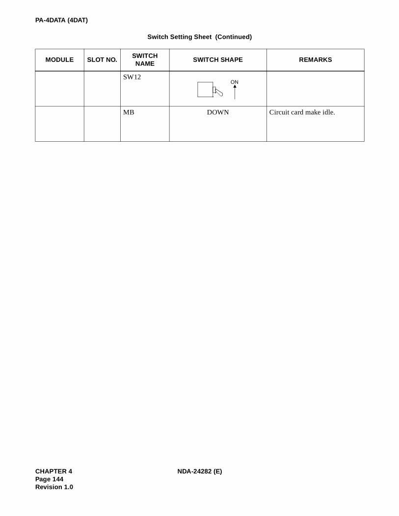
PA-4DATA (4DAT)
SW12
MB DOWN Circuit card make idle.
Switch Setting Sheet (Continued)
MODULE SLOT NO.SWITCH NAME
SWITCH SHAPE REMARKS
ON
CHAPTER 4 NDA-24282 (E)Page 144Revision 1.0

PA-4DATB (DAT)
PA-4DATB (DAT)
1. General Function
The PA-4DATB (DAT) circuit card is used as a Digital Announcement Trunk supporting service featuresrelated to announcement functions such as Automated Attendant, Delay Announcement Attendant,Announcement Service (for Hotel System). Depending on the switch setting, this circuit card works in oneof the following three modes.
• 64-second mode (maximum 4 CHs/card)
• 128-second mode (maximum 2 CHs/card)
• 240-second mode (maximum 1 CH/card)
A message can be recorded from either a tape recorder or a telephone set. In addition, this circuit card canbe used as an external music source.
Figure 4-14 Location of PA-4DATB (DAT) card within the system
DLKC
CPU GT
COT
SW
PUBLICNETWORK
INCOMING CALL
LOCAL I/O BUS
ATTCON
DAT
COT
INT INT
CALLING PARTY
CALLING PARTYINCOMING CALLATI
This diagram shows an example when this card is used for Delay Announcement Attendant.
We are sorry, the line isbusy now. Please stayon the line.
(PRERECORDED MESSAGE)
NDA-24282 (E) CHAPTER 4Page 145
Revision 1.0

PA-4DATB (DAT)
2. Mounting Location/Condition
The PA-4DATB (DAT) card can be mounted in any universal slot as shown below.
Mounting Module PIMU-A
00 01 02 03 04 05 06 07 08 09 10 11 12 13 14 15 16 17 18 19 20 21 22 23
Note: Indicates universal slots for line/trunk circuit cards.
Mounting Module PIME
00 01 02 03 04 05 06 07 08 09 10 11 12 13 14 15 16 17 18 19 20 21 22 23
Note: Indicates universal slots for line/trunk circuit cards.
CHAPTER 4 NDA-24282 (E)Page 146Revision 1.0

PA-4DATB (DAT)
3. Face Layout of Lamps, Switches, and Connectors
The face layout of lamps, switches, and connectors on this circuit card is shown below.
4. Lamp Indications
The contents of lamp indications of this circuit card are shown in the table below.
LAMP COLOR STATE
OPE Green Remains lit while this circuit card is operating.
N-OPE Red Remains lit while this circuit card is in make-busy state.
BL4
BL7
GreenLights when the corresponding circuit (No 0 through No. 3 circuits) is connected to a recording source.
FlashFlashes while message recording is in progress on the corresponding circuit (No. 0 through No. 3 circuit).
BL0
BL3
Red Lights when the corresponding circuit (No. 0 through No. 3 circuits) is busy.
FlashFlashes when the corresponding circuit (No. 0 through No. 3 circuits) is in make-busy state or has not been assigned in the system.
OPE
N-OPE
MBML7
ML0
START
3 2 1 0
SW1
SW5
SW6
SW4
JP0
MB RQ
MRCS
JACK
WR
SW3
SW7 SW2
~~
NDA-24282 (E) CHAPTER 4Page 147
Revision 1.0
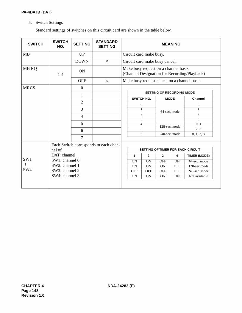
PA-4DATB (DAT)
5. Switch Settings
Standard settings of switches on this circuit card are shown in the table below.
SWITCHSWITCH
NO.SETTING
STANDARDSETTING
MEANING
MB UP Circuit card make busy.
DOWN × Circuit card make busy cancel.
MB RQ
1-4ON
Make busy request on a channel basis(Channel Designation for Recording/Playback)
OFF × Make busy request cancel on a channel basis
MRCS 0
1
2
3
4
5
6
7
SW1
SW4
Each Switch corresponds to each chan-nel ofDAT: channelSW1: channel 0SW2: channel 1SW3: channel 2SW4: channel 3
SETTING OF RECORDING MODE
SWITCH NO. MODE Channel
0
64-sec. mode
0
1 1
2 2
3 3
4128-sec. mode
0, 1
5 2, 3
6 240-sec. mode 0, 1, 2, 3
~
SETTING OF TIMER FOR EACH CIRCUIT
1 2 2 4 TIMER (MODE)
ON ON OFF ON 64-sec. mode
ON ON ON OFF 128-sec mode
OFF OFF OFF OFF 240-sec. mode
ON ON ON ON Not available
CHAPTER 4 NDA-24282 (E)Page 148Revision 1.0

PA-4DATB (DAT)
SWITCHSWITCH
NO.SETTING
STANDARDSETTING
MEANING
SW5
1
2
3ON Compression Law: µ-law
OFF Compression Law: A-law
4ON To be used as external hold tone source
OFF To be used as announcement equipment
SW61
ON Single playback of No. 0 channel Note 2
OFF Multiple playback of No. 0 channel
2ON Single playback of No. 1 channel Note 2
OFF Multiple playback of No. 1 channel
3ON Single playback of No. 2 channel Note 2
OFF Multiple playback of No. 2 channel
4ON Single playback of No. 3 channel Note 2
OFF Multiple playback of No. 3 channel
5ON RAM Test data - clear
OFF × RAM Test data - store
6 OFF × Not used
7 OFF × Not used
8 OFF × Not used
Note 3: When this card is used as announcement equipment, SW6-1~SW6-4 should be set OFF.
Note 4: For Automated Attendant and Delay Announcement-Attendant, set single playback (ON).
Note: Setting of Recording/Playback Timer shouldcorrespond to that of SW1-SW4.
SETTING OF ANNOUNCEMENT RECORDING/PLAYBACK TIME
SW5-1 SW5-2 RECORDING/PLAYBACK TIME
OFF ON 64-sec. Recording/Playback
ON OFF 128-sec. Recording/Playback
OFF OFF 240-sec. Recording/Playback
NDA-24282 (E) CHAPTER 4Page 149
Revision 1.0

PA-4DATB (DAT)
SWITCHSWITCH
NO.SETTING
STANDARDSETTING
MEANING
SW71
ON Activation of RAM Test
OFF × Normal setting
2ON Port Microprocessor is reset when MBR key is ON.
OFF × Port Microprocessor is not reset when MBR key is ON.
3 OFF × Not used
4 OFF × Not used
WR UP For recording from the phone jack
DOWN × Normal setting
STARTUP
When starting recording from the phone jack or play-back.
DOWN × Normal setting
Jumper Setting
SWITCHSWITCHSHAPE
SETTING DESCRIPTION
JP0
LEFT Compression Law: µ-law
RIGHT Compression Law: A-lawLEFT RIGHT
CHAPTER 4 NDA-24282 (E)Page 150Revision 1.0

PA-4DATB (DAT)
6. External Interface
When this card is used as an external music-on-hold source, the following cable connection is required.
Figure 4-15 LT Connector Lead Accommodation (PIMU-A)
E FM
E FM26 27 28 29 30 31 32 33 34 35 36 37 38 39 40 41 42 43 44 45 46 47 48 49 50
00 01 02 03 04 05 06 07 08 09 10 11 12 13 14 15 16 17 18 19 20 21 22 23
LT0
PIMC
LT Connector Name
Slot No.
1 2 3 4 5 6 7 8 9 10 11 12 13 14 15 16 17 18 19 20 21 22 23 24 25
Group No.
LT1 LT2 LT3 LT4 LT5 LT6 LT7 LT8 LT9 LT10 LT11
01
00
03
02
05
04
07
06
09
08
11
10
01
00
03
02
05
04
07
06
09
08
11
10
15 14 13 12
19 18 17 16
23 22 21 20
15 14 13 12
19 18 17 16
23 22 21 20
Highway Block 0 1 2 6 7 83 4 5 9 10 11
26 27 28 29 30 31 32 33 34 35 36 37 38 39 40 41 42 43 44 45 46 47 48 49 50
1 2 3 4 5 6 7 8 9 10 11 12 13 14 15 16 17 18 19 20 21 22 23 24 25
26 27 28 29 30 31 32 33 34 35 36 37 38 39 40 41 42 43 44 45 46 47 48 49 50
1 2 3 4 5 6 7 8 9 10 11 12 13 14 15 16 17 18 19 20 21 22 23 24 25
LT0, 2, 4, 6, 8, 10 ConnectorAccommodated in *2Accommodated in *1
LT1, 3, 5, 7, 9, 11 ConnectorAccommodated in *3
LT1, 3, 5, 7, 9, 11 Connector
E FM
Mounting Module PIMC
1 2 3 1 2 3 1 2 3 1 2 3 1 2 3 1 2 3
NDA-24282 (E) CHAPTER 4Page 151
Revision 1.0

PA-4DATB (DAT)
Figure 4-16 LT Connector Lead Accommodation (PIME)
E FM
E FM26 27 28 29 30 31 32 33 34 35 36 37 38 39 40 41 42 43 44 45 46 47 48 49 50
00 01 02 03 04 05 06 07 08 09 10 11 12 13 14 15 16 17 18 19 20 21 22 23
LT2
PIME
Slot No.
1 2 3 4 5 6 7 8 9 10 11 12 13 14 15 16 17 18 19 20 21 22 23 24 25
Group No.
LT3 LT4 LT5 LT6 LT7 LT8 LT9 LT10 LT11 LT12 LT13
01
00
03
02
05
04
07
06
09
08
11
10
01
00
03
02
05
04
07
06
09
08
11
10
15
14
13
12
19
18
17
16
23
22
21
20
15
14
13
12
19
18
17
16
21
20
Highway BlockHW0 HW1 HW2 HW11
26 27 28 29 30 31 32 33 34 35 36 37 38 39 40 41 42 43 44 45 46 47 48 49 50
1 2 3 4 5 6 7 8 9 10 11 12 13 14 15 16 17 18 19 20 21 22 23 24 25
26 27 28 29 30 31 32 33 34 35 36 37 38 39 40 41 42 43 44 45 46 47 48 49 50
1 2 3 4 5 6 7 8 9
10 11 12 13 14 15 16 17 18 19 20 21 22 23 24 25
LT0, 2, 4, 6, 8, 10, 12, 14 Connector
Accommodated in *2Accommodated in *1LT1, 3, 5, 7, 9, 11, 13, 15 Connector
Accommodated in *3LT1, 3, 5, 7, 9, 11, 13, 15 Connector
E FM
Mounting Module PIME
1 2 3 1 2 3 1 2 3 1 2 3 1 2 3 1 2 3
LT0 LT1
24 25
LT14 LT15
1 2 3 1 2
HW3 HW4 HW5 HW6 HW7 HW8 HW9 HW10
CHAPTER 4 NDA-24282 (E)Page 152Revision 1.0

PA-4DATB (DAT)
7. Reference
How to Record a Message
• Prior to your recording, set switches on the DAT card according to the following example.
SWITCH SETTINGS ON DAT (Example <240 sec mode>)
• Connect a tape recorder to the DAT card with a cable.
• Turn On the MBRQ key to make busy a channel to be recorded.(To record a message in the 240 sec. mode, all circuits must be placed into MB state.)
• Turn the WR key upwards.
(The corresponding BL lamp lights green indicating the tape recorder has been connected to the cir-cuit.)
• Turn the START key upwards.
(The corresponding BL lamp starts flashing.)
• Start the tape recorder and record your message in the designated channel.
<recording>
• The corresponding BL lamp (BL0 ~ BL7) lights steadily. (Recording ends.)
• Return the START, WR key to the previous position.
SWITCH SETTING DESCRIPTION
SW1
SW4
Timer Value for Channel 0-3: 240 sec.
SW5 Circuit Card Timer: 60 sec. A-law/µ-law: A-law External Music Source/ An-nouncement Equipment: Announcement Equipment
SW6 Single/Repeated Playback: Repeated Playback
MRCS Channel Designation:240 sec mode
DAT
Front
Jackearphone jack (3.6 ø)
Tape Recorder
NDA-24282 (E) CHAPTER 4Page 153
Revision 1.0

PA-4DATB (DAT)
How to Play Back the Recorded Message
• Playback from a telephone set• Set the related switches on the PA-4DATB (DAT) card.
• Seize a specific channel by “Individual Trunk Access”.• Hear the recorded message.
• Playback from the phone jack on PA-4DATB (DAT) card.
• Connect a earphone to the phone jack on the PA-4DATB (DAT) card.• Select your desired channel (0~3) by the MRCS switch.
• Turn the START key upwards.• Hear the recorded message.
CHAPTER 4 NDA-24282 (E)Page 154Revision 1.0

PA-4DTLA (4DTL)
PA-4DTLA (4DTL)
1. Function
This circuit card is a trunk/line card that interfaces the NEAX2400 to four Data Modules.
2. Mounting Location/Condition
The mounting locations of this circuit card and the conditions related to mounting are shown below.
(a) When this circuit card is mounted in PIMU-A
NEAX2400IMS
Navigator MIS
Host4DTLA
16ELC
MDF
Navigator Remote
Terminal
MDFDM
Dterm /DataAdapter
Data TerminalEquipment
(DTE)
01 02 03 04 05 06 07 08 09 10 11 12 13 14 15 16 17 18 19 20 21 22 23
Mounting Module PIMU-A
00
Note: Indicates that the slots are a universal slot for line/trunk circuit cards.
NDA-24282 (E) CHAPTER 4Page 155
Revision 1.0

PA-4DTLA (4DTL)
(b) When this circuit card is mounted in PIMB
3. Face Layout of Lamps, Switches, and Connectors
The face layout of lamps, switches, and connectors of this circuit card is shown below.
Mounting Module PIMB
01 02 03 04 05 06 07 08 09 10 11 12 13 14 15 16 17 18 19 20 21 22 2300
Note: Indicates that the slots are a universal slot for line/trunk circuit cards.
OPE
N-OPE
MB
BL3BL2BL1
BL0
RFBS
ECSL
SW1
SFBS
RSBS
SW0
Front ViewSide View
CHAPTER 4 NDA-24282 (E)Page 156Revision 1.0

PA-4DTLA (4DTL)
4. Lamp Indications
The contents of lamp indications of this circuit card are shown in the table below.
5. Switch Settings
Standard settings of various switches on this circuit card are shown in the table below.
LAMP NAME COLOR Status STATE
OPE Green ON The Port Microprocessor is operating normally.
N-OPE Red ON The Port Microprocessor is not operating due to MB switch or software.
BL0
BL3Red
ON The circuit is in use.
Blinking (1/sec.)
The circuit is out of service due to switch setting or software.
SWITCH TYPE AND
NAMEFUNCTION
SWITCH
ELEMENT POSITION MEANING
Toggle SwitchMB
Make Busy (entirecircuit card)
UP Take circuit card out of service.
DOWN Normal operation.
“Piano” keys MB0 ~ MB3 Busy out individual
circuits0 ~ 3
UP (left) Normal operation.
DOWN (right)Take corresponding circuit out of ser-vice.
Dip SwitchSW0
1 ~ 4 Must be ON
DIP SwitchRFBS Received framing bit
control1 ~ 4Note
ON Firmware control; DSR always ON.
OFFHardware control; DSR set by DTE (standard setting).
DIP SwitchSFBS Sent framing bit
control1 ~ 4Note
ON Firmware control; DSR always ON.
OFFHardware control; DSR set by DTE (standard setting).
DIP Switch RSBS
Not used 1 ~ 4 OFF(Standard setting.)
DIP Switch ECSL
Not used 1 ~ 4 OFF(Standard setting.)
Note: Each switch element (1 ~ 4) controls the corresponding circuit (0 ~ 3).
~
NDA-24282 (E) CHAPTER 4Page 157
Revision 1.0

PA-4DTLA (4DTL)
6. External Interface
Accommodation of the LT connector leads of this circuit card and connecting route diagram are shownbelow.
(a) LT Connector Lead Accommodation when this circuit card is mounted in PIMA
Figure 4-17 LT Connector Leads Accommodation of PIMU-A (1/2)
26 27 28 29 30 31 32 33 34 35 36 37 38 39 40 41 42 43 44 45 46 47 48 49 50
1 2 3 4 5 6 7 8 9 10 11 12 13 14 15 16 17 18 19 20 21 22 23 24 25
LT Connector Accommodation
00 01 02 03 04 05 06 07 08 09 10 11 12 13 14 15 16 17 18 19 20 21 22 23
LT0
PW
RPIMA
LT Connector Name
Slot No.
LT1, 3, 5, 7, 9, 11 Connector
Accommodated in *2
Group No.
LT1 LT2 LT3 LT4 LT5 LT6 LT7 LT8 LT9 LT10 LT11
01
00
03
02
05
04
07
06
09
08
11
10
01
00
03
02
05
04
07
06
09
08
11
10
15 14 13 12
19 18 17 16
23 22 21 20
15 14 13 12
19 18 17 16
23 22 21 20
Highway Block 0 1 2 6 7 83 4 5 9 10 11
26 27 28 29 30 31 32 33 34 35 36 37 38 39 40 41 42 43 44 45 46 47 48 49 50
LT0, 2, 4, 6, 8, 10 Connector
Accommodated in *1
1 2 3 4 5 6 7 8 9 10 11 12 13 14 15 16 17 18 19 20 21 22 23 24 25
* 1
PW
R
* 1
* 1
* 1
* 1
* 1
* 2
* 2
* 2
* 2
* 2
* 2
B00B10B01B11B02B12B03B13
A00A10A01A11A02A12A03A13
B00B10B01B11B02B12B03B13
A00A10A01A11A02A12A03A13
CHAPTER 4 NDA-24282 (E)Page 158Revision 1.0

PA-4DTLA (4DTL)
Figure 4-17 LT Connector Leads Accommodation of PIMU-A (2/2)
LT Connector Accommodation
26 27 28 29 30 31 32 33 34 35 36 37 38 39 40 41 42 43 44 45 46 47 48 49 50
00 01 02 03 04 05 06 07 08 09 10 11 12 13 14 15 16 17 18 19 20 21 22 23
LT0
PW
RPIMA
LT Connector Name
Slot No.
LT1, 3, 5, 7, 9, 11 Connector
Accommodated in *3
1 2 3 4 5 6 7 8 9 10 11 12 13 14 15 16 17 18 19 20 21 22 23 24 25
Group No.
LT1 LT2 LT3 LT4 LT5 LT6 LT7 LT8 LT9 LT10 LT11
01
00
03
02
05
04
07
06
09
08
11
10
01
00
03
02
05
04
07
06
09
08
11
10
15 14 13 12
19 18 17 16
23 22 21 20
15 14 13 12
19 18 17 16
23 22 21 20
Highway Block 0 1 2 6 7 83 4 5 9 10 11
PW
R
* 3
* 3
* 3
* 3
* 3
* 3
B00B10B01B11B02B12B03B13
A00A10A01A11A02A12A03A13
NDA-24282 (E) CHAPTER 4Page 159
Revision 1.0

PA-4DTLA (4DTL)
(b) LT Connector Lead Accommodation when this circuit card is mounted in PIMB
Figure 4-18 LT Connector Leads Accommodation of PIMB (1/2)
LT Connector Accommodation
00 01 02 03 04 05 06 07 08 09 10 11 12 13 14 15 16 17 18 19 20 21 22 23
LT0
PIMB
LT Connector Name
Slot No.
Group No.
LT1 LT2 LT3 LT4 LT5 LT7 LT8 LT9 LT10
03
02
07
06
11
10
15
14
19
18
23
22
15 14 13 12
07 06 05 04
15 14 13 12
23 22 21 20
Highway Block 0 1 2 6 7 8
9
3 4 5 10
11
LT6
23 22 21 20
07 06 05 04
15 14 13 12
23 22 21 20
01
00
05
04
09
08
13
12
17
16
21
20
11 10 09 08
03 02 01 00
11 10 09 08
19 18 17 16
19 18 17 16
03 02 01 00
11 10 09 08
19 18 17 16
03
02
01
00
07
06
05
04
8
9
10
11
4
5
6
7
2
3
0
1
* 1
* 1
* 1
* 1
* 1
* 1
* 2
* 2
* 2
* 2
* 2
LT1, 3, 5, 7, 9, 11 Connector
Accommodated in *2
26 27 28 29 30 31 32 33 34 35 36 37 38 39 40 41 42 43 44 45 46 47 48 49 50
LT0, 2, 4, 6, 8, 10 Connector
Accommodated in *1
1 2 3 4 5 6 7 8 9 10 11 12 13 14 15 16 17 18 19 20 21 22 23 24 25
B00B10B01B11B02B12B03B13
A00A10A01A11A02A12A03A13
B00B10B01B11B02B12B03B13
A00A10A01A11A02A12A03A13
26 27 28 29 30 31 32 33 34 35 36 37 38 39 40 41 42 43 44 45 46 47 48 49 50
1 2 3 4 5 6 7 8 9 10 11 12 13 14 15 16 17 18 19 20 21 22 23 24 25
CHAPTER 4 NDA-24282 (E)Page 160Revision 1.0

PA-4DTLA (4DTL)
Figure 4-18 LT Connector Leads Accommodation of PIMB (2/2)
LT Connector Accommodation
00 01 02 03 04 05 06 07 08 09 10 11 12 13 14 15 16 17 18 19 20 21 22 23
LT0
PIMB
LT Connector Name
Slot No.
Group No.
LT1 LT2 LT3 LT4 LT5 LT7 LT8 LT9 LT10
03
02
07
06
11
10
15
14
19
18
23
22
15 14 13 12
07 06 05 04
15 14 13 12
23 22 21 20
Highway Block 0 1 2 6 7 8
9
3 4 5 10
11
LT6
23 22 21 20
07 06 05 04
15 14 13 12
23 22 21 20
01
00
05
04
09
08
13
12
17
16
21
20
11 10 09 08
03 02 01 00
11 10 09 08
19 18 17 16
19 18 17 16
03 02 01 00
11 10 09 08
19 18 17 16
03
02
01
00
07
06
05
04
8
9
10
11
4
5
6
7
2
3
0
1
* 3
* 3
* 3
* 3
* 3
26 27 28 29 30 31 32 33 34 35 36 37 38 39 40 41 42 43 44 45 46 47 48 49 50
LT1, 3, 5, 7, 9, 11 Connector
Accommodated in *3
1 2 3 4 5 6 7 8 9 10 11 12 13 14 15 16 17 18 19 20 21 22 23 24 25
B00B10B01B11B02B12B03B13
A00A10A01A11A02A12A03A13
NDA-24282 (E) CHAPTER 4Page 161
Revision 1.0

PA-4DTLA (4DTL)
NEAX2400 IMS
B00
MDF
G
RA00
4DTL ModularJack
DTERS232
BB10
YA10
CHAPTER 4 NDA-24282 (E)Page 162Revision 1.0

PA-CC98 (ETHER)
PA-CC98 (ETHER)
Ethernet Controller
1. Functional Outline
In the NEAX2400 ICS OAI System, this circuit card supports the functions for interface between the CPU(IP) circuit card and the external computer. If circuit card type, this circuit card is directly connected withthe CPU card (PA-CP53). If module type, being paired with PA-GT (MBB) card, it connects the InterfaceProcessor (IP) and the User Application Processor (UAP) through a LAN.
CPU (No.0 Sys) (PA-CP53)
ETHER
(PA-CC98)
Ethernet
(a) If circuit card type
CPU (No.0 Sys) (PA-CP54)
CPU (No.1 Sys) (PA-CP54)
MBB (PA-GT16)
ALMC (PA-AL16)
ETHER (PA-CC98)
Ethernet
(b) If module type (dual system configuration)
Memory Bus (No.0 System)
Memory Bus (No.1 System)
NDA-24282 (E) CHAPTER 4Page 163
Revision 1.0

PA-CC98 (ETHER)
2. Circuit Card Mounting Locations/Conditions
The mounting locations and conditions of this circuit card are shown below.
(a) In the case of circuit card type
• When mounting in the PIMU-A
• When mounting in the PIMB
Mounting Module PIMU-A
00 01 02 03 04 05 06 07 08 09 10 11 12 13 14 15 16 17 18 19 20 21 22 23
Note: Indicates the mounting locations of this circuit card.
Mounting Module PIMB
00 01 02 03 04 05 06 07 08 09 10 11 12 13 14 15 16 17 18 19 20 21 22 23
Note: Indicates the mounting locations of this circuit card.
CHAPTER 4 NDA-24282 (E)Page 164Revision 1.0

PA-CC98 (ETHER)
(a) In the case of module type
3. Locations of Lamps, Switches, and Connectors
The locations of lamps, switches, and connectors equipped on this circuit card are shown below.
Mounting Module APM
00 01 02 03 04 05 06 07 08 09 10 11 12 13 14 15 16 17 18 19 20 21 22 23
PA
-CC
98
SW0
BUS
LAN
FUSE
OPESW1 ERR
S2S1
S3
SW2
NDA-24282 (E) CHAPTER 4Page 165
Revision 1.0

PA-CC98 (ETHER)
4. Lamp Indications
The meaning of indication of each lamp on this circuit card is shown below.
5. Switch Setting
Each switch setting on this circuit card and its meaning are shown in the tables on the following pages.
The CC98 Internet address is set by using the AIPT MAT command. For ICS and IMX, Internet is set onlyby the AIPT command. For HDS (IMG) configurations, the AIPT command is used for setting the Internetaddress for software versions J04.7 and higher.
Contact NEC Personnel for Internet address settings in HDS software versions below J04.7.
Each CC98 card must have a unique MAC address. This MAC address allows each CC98 to be differentfrom each other and different from any other LAN system. The MAC address is twelve digits in length.Switches SW0 and SW1 are used to set the lowest three digits. The remainder of the MAC address is fixed.The Internet address set by AIPT is used with the MAC address to allow the CC98 to connect to LAN net-works.
Note: If two or more CC98 cards are connected on the same LAN, each must have a unique MAC address.
LAMP COLOR MEANING OF INDICATION
OPE Green Remains lit while this circuit card is in operating status
ERR
Red When a fault has occurred within this circuit card, this lamp lights or flashes to-gether with lamp S1, S2, or S3 so as to specify the contents of the faultRed
Flash
S1GreenFlash
Flashes when data frame has been sent out onto the LAN
S2 Green Lights when this circuit card is ready to operate
S3 Green Remains lit while the power supply to this circuit card is on
CHAPTER 4 NDA-24282 (E)Page 166Revision 1.0

PA-CC98 (ETHER)
SWITCHDIP SW
No.SETTING
DEFAULT SETTING
MEANING
SW0
(8 DIP Switches)
1ON Sets 0, corresponding to bit 0 of MAC address
OFF Sets 1, corresponding to bit 0 of MAC address
2ON Sets 0, corresponding to bit 1 of MAC address
OFF Sets 1, corresponding to bit 1 of MAC address
3ON Sets 0, corresponding to bit 2 of MAC address
OFF Sets 1, corresponding to bit 2 of MAC address
4ON Sets 0, corresponding to bit 3 of MAC address
OFF Sets 1, corresponding to bit 3 of MAC address
5ON Sets 0, corresponding to bit 4 of MAC address
OFF Sets 1, corresponding to bit 4 of MAC address
6ON Sets 0, corresponding to bit 5 of MAC address
OFF Sets 1, corresponding to bit 5 of MAC address
7ON Sets 0, corresponding to bit 6 of MAC address
OFF Sets 1, corresponding to bit 6 of MAC address
8ON Sets 0, corresponding to bit 7 of MAC address
OFF Sets 1, corresponding to bit 7 of MAC address
Note: For switch setting for MAC address, refer to [Reference] shown below in thesetting of SW1. For details of switch setting for Internet address, refer to theAIPT command explained in Chapter 7, ”PBX and ACD Command Pro-gramming”.
SW1
(8 DIP Switches)
1ON Sets 0, corresponding to bit 8 of MAC address
OFF Sets 1, corresponding to bit 8 of MAC address
2ON Sets 0, corresponding to bit 9 of MAC address
OFF Sets 1, corresponding to bit 9 of MAC address
3ON Sets 0, corresponding to bit 10 of MAC address
OFF Sets 1, corresponding to bit 10 of MAC address
1 2 3 4 5 6 7 8ON
1 2 3 4 5 6 7 8ON
NDA-24282 (E) CHAPTER 4Page 167
Revision 1.0

PA-CC98 (ETHER)
SW1 (Continued)4
ON Sets 0, corresponding to bit 11 of MAC address
OFF Sets 1, corresponding to bit 11 of MAC address
5 ON × Fixed
6 ON × Fixed
7 ON × Fixed
8 ON × Fixed
[Reference]
Setting of MAC address
On LAN and TCP/IP, this circuit card can have the following addresses and ports.
MAC Address: 000032250xxxH (48 bits)
TCP Port Numbers: 16 port numbers of 1024 ~ 1039
The last 12 bits of MAC address must be set by switches SW0 and SW1 before starting up this circuit card.
(Ex.)When MAC address is to be set to 000032250123H:
By dividing 12 bits into 4-bit units (refer to the table on the right side), and set the switches as shown below.
SW2
(Rotary SW)
0
Fixed setting (When operating)
SWITCHDIP SW
No.SETTING
DEFAULT SETTING
MEANING
0H
1H
2H
3H
4H
5H
6H
7H
8H
9H
AH
BH
CH
DH
EH
FH
Relation between the value of 4 Bits and Switch Setting
Hex Switch Setting
0 = Fixed (not used)
SW0 SW1
1 2 3 4 5 6 7 8ON
3 2
1 2 3 4 5 6 7 8ON
1 0
CHAPTER 4 NDA-24282 (E)Page 168Revision 1.0

PA-CC98 (ETHER)
MODULE SLOT SWITCH SWITCH SHAPE REMARKS
SW0
SW1
SW2
Fixed for the system
1 2 3 4 5 6 7 8ON
1 2 3 4 5 6 7 8ON
0
NDA-24282 (E) CHAPTER 4Page 169
Revision 1.0

PA-GT16 (MBB)
PA-GT16 (MBB)
Memory Bus Buffer
1. Functional Outline
This circuit card is used in the OAI module type for the NEAX2400 IMX and ICS OAI System. It is a circuitcard which repeats the memory bus on PA-CP54 (CPU) card side to ETHER (Ethernet Interface) gate card.
2. Circuit Card Mounting Locations/Conditions
Mounting Module APM
00 01 02 03 04 05 06 07 08 09 10 11 12 13 14 15 16 17 18 19 20 21 22 23
PA
-GT
16
CPU (No.0 Sys)
(PA-CP54)
CPU (No.1 Sys)
(PA-CP54)
MBB
(PA-GT16)
ALMC
(PA-AL16)
ETHER
(PA-CC98)
Ethernet
Position within the system
Memory Bus (No.0 System) Memory Bus (No.1 System)
CHAPTER 4 NDA-24282 (E)Page 170Revision 1.0

PA-GT16 (MBB)
3. Locations of Lamps, Switches, and Connectors
The locations of lamps, switches, and connectors equipped on this circuit card are shown below.
4. Lamp Indications
The meaning of indication of each lamp on this circuit card is shown below.
LAMP COLOR MEANING OF INDICATION
OPE Green Remains lit while this circuit card and ETHER card are normally operating
LAN ALM RedLights when the processor in ETHER card has become faulty or when ETHER card is not correctly connected with this circuit card
SW0
BUS
OPE
SEG
MB
LAN ALM
MBRQ
NDA-24282 (E) CHAPTER 4Page 171
Revision 1.0

PA-GT16 (MBB)
5. Switch Setting
Each switch setting on this circuit card and its meaning are shown below.
SWITCHDIP SW
No.SETTING
DEFAULT SETTING
MEANING
MB
(Toggle SW)
UP Circuit card make-busy
DOWN
Circuit card make-busy cancel (Circuit card is in operating status)
MBRQ
(Toggle SW)
UPCircuit card make-busy request
DOWN× Circuit card make-busy request cancel
(Circuit card is in operating status)
SEG
(Rotary SW)
F
× Sets memory address area to XF0000H ~ XFFFFFH
SW0
(8 DIP Switches)
1 OFF × Fixed
2ON Interrupt is inhibited
OFF × Interrupt is not inhibited
3
ONSets the equipment number of this circuit card to 1
OFF× Sets the equipment number of this circuit card to
0
4 OFF × Not used
5 ON × Fixed
6 OFF × Fixed
7 OFF × Fixed
8 OFF × Fixed
ON(MB)
OFF
ON(MB)
OFF
1 2 3 4 5 6 7 8ON
CHAPTER 4 NDA-24282 (E)Page 172Revision 1.0

PA-GT16 (MBB)
Switch Setting Table
MODULE NAME
SLOT SW NAME SWITCH SHAPE REMARKS
APM 12
MB
UP: Circuit card make-busyDOWN: Circuit card make-busy cancel
(Circuit card in operating status)
MBRQ
SEG
Fixed
SW0
ON
ON
F
1 2 3 4 5 6 7 8ON
NDA-24282 (E) CHAPTER 4Page 173
Revision 1.0

This page is for your notes.
CHAPTER 4 NDA-24282 (E)Page 174Revision 1.0

CHAPTER 5 OFFICE DATA DESIGN
1. GENERAL
This chapter explains the office data design for the ACD in the IMX system.
2. BASIC OFFICE DATA ASSIGNMENT
This section explains how to assign the basic office data. Items covered in this section include the following:
2.1 Back-Up UCD
2.2 ACD In a Fusion Network Data Assignment
NDA-24282 (E) CHAPTER 5Page 175
Revision 1.0

OFFICE DATA DESIGN
2.1 BACK-UP UCD
When a system provides the back-up UCD group, ACD calls will be routed to the back-up UCD group if ACDsystem is corrupted.
Design of UCD station
• Pattern 1
400 (ACD)
300 (PBX)
AMNON ASHU
401 (ACD)
301 (PBX)
501 UCD STA
402 (ACD)
302 (PBX)
Supervisory position Agent position 1 Agent position 2
500 UCD
Control STA
502 UCD STA
• UCD STA
• Pattern 2
400 (ACD)
300 (PBX)
AMNON
401 (ACD)
301 402 (ACD)
302
Supervisory position Agent position 1 Agent position 2
500 UCD
ControlSTA
• PBX • UCD STA
• PBX
ASHU
• PBX
• Pattern 3
400 (ACD)
300
AMNON
ASHU
401 (ACD)
301 402 (ACD)
302
Supervisory position Agent position 1 Agent position 2
• UCD STA(PBX) • PBX
• UCD STA
501UCD
Control STA
CHAPTER 5 NDA-24282 (E)Page 176Revision 1.0

OFFICE DATA DESIGN
<Back-up UCD for Fusion service>Design of UCD stationAssign the ACD positions in the self-node as UCD controlling station at each node. By this programming, ACDincoming calls terminated to the trunk in the self-node can be distributed to the UCD group member in the self-node even when link down or the remote system down is occurred.When there is no ACD positions in the node, the back-up UCD group may be organized by the non-ACD posi-tion.
• Pattern 1 when a back-up UCD group is formed by ACD positions in a node.
ACD calls are distributed to the UCD group member in the self-node.
NEC
NEC
.....
.....
•
.....
Public Network
(provides ACDP)
ICT
Node A
Node B
UCD Group (b)UCD Group (a)
UCD Group of Non-ACD stations
UCD Controlling Station
UCD Controlling Station
ACD incoming call
ACD incoming call
ICT
NON-ACD Stations In the node with no ACD positions
ACD agent
UCD DistributionUCD Distribution
Public
Network
ACD agent
NDA-24282 (E) CHAPTER 5Page 177
Revision 1.0

OFFICE DATA DESIGN
• Pattern 2 when a back-up UCD group is formed by ACD positions in multiple nodes.
When ACD positions in multiple nodes belong to an ACD split, assign back-up UCD group for the split todivide into two groups and assign the UCD controlling station number to ACD positions in the self-node andthe remote node.
NEC
NEC
(provides ACDP)
ICT
..... .....
.....
Node A
Node B
UCD Group (b)
UCD Group (a)
.....
UCD Controlling Station
UCD Controlling Station
UCD Distribution OK
UCD Distribution OK
ACD incoming call
ICT
Public Network
Public Network
ACD incoming call
CHAPTER 5 NDA-24282 (E)Page 178Revision 1.0

OFFICE DATA DESIGN
When a UCD group is organized by ACD positions in multiple nodes, ACD incoming calls cannot be distributedto ACD positions in the node where UCD controlling station is not accommodated when the link connecting thenodes is down.
ACD incoming calls terminated at the trunk in Node B are distributed to UCD group members in Node B.
ACD incoming calls are not distributed to any position and the caller hears the reorder tone.
NEC
NEC
(provides ACDP)
ICT LINK DOWN
..... .....
Node A
Node B
UCD Distribution OK
UCD Group of ACD Positions
Public Network
Public Network
ACD incoming call
ICT
UCD Distribution NG
UCD Controlling Station
NEC
NEC
(provides ACDP)
ICT LINK DOWN
..... .....
Node A
Node B
UCD Group
UCD Controlling Station
Public Network
Public Network
ACD incoming calls
ICT
UCD Distribution NG
NDA-24282 (E) CHAPTER 5Page 179
Revision 1.0

OFFICE DATA DESIGN
Step 1: ASHU (Station Hunting - UCD)/ASHUN (for Fusion)Assign UCD group data
Note: ASHU command data and ASHUN command data cannot be used in a system.
Step 2: AMNO (Monitored Number)/AMNON (for Fusion)• Assign “1” on a parameter UCD.
• Assign the control station number of the back-up UCD per Monitored number.
CHAPTER 5 NDA-24282 (E)Page 180Revision 1.0

OFFICE DATA DESIGN
2.2 ACD IN A FUSION NETWORK DATA ASSIGNMENT
This section provides general information about ACD in an Fusion Network and also, network establishmentconditions, data programming. For the function differences, this information is classified into the following twofunctions.
Function 1 - ACD agents in a node providing ACDP can answer the ACD incoming calls via access toACD trunks in the remote node. This is called “ACD Trunk for Fusion” in this manual.
Function 2 - ACD agents in multiple nodes can answer ACD incoming calls since multiple ACDPs can beprovided in a Fusion Network (PBX software Series 7400 feature). This is called “MultipleACDPs in an Fusion Network” in this manual.
Note: Feature [A-133] AGENT ANYWHERE allows ACD calls to be terminated to agents in remote nodes sinceSeries 7300 software. See Section 3, “ACD Service Feature” in this chapter for details.
Conditions for Network Establishment
1. Telephone Number (maximum 5 digits) is used for the station number type (both PBX line and ACD line)to activate ACD system through Fusion Network. Note 1
2. Logical Route (1-254: route numbers more than 254 are not available) is used for the route type to activateACD system through Fusion Network. The tables below show which data programming is changed in ac-cordance with these conditions in terms of data and commands.
Basic Office Data
Data Description Notice
Monitor number 1. AMNON is used in place of AMNO2. Telephone number for Monitor number (pilot number) is assigned in ALGNN com-
mand before the monitor number data assignment.3. ACNON is used in place of ACNO
Announcement data AADTN is used in place of AADT
Back up-UCD data ASHUN is used in place of ASHU. See “Uniform Call Distribution (UCD) [U-1]” in Fea-ture Programming Manual.
Other data Logical route number (1-254) and telephone number (max. 5 digits) are used.
1
NDA-24282 (E) CHAPTER 5Page 181
Revision 1.0

OFFICE DATA DESIGN
ACD Command Data(See Chapter 7, “PBX and ACD Command Programming” for details of each command.)
Data Description Notice
ACDANA Telephone number (monitor number = pilot number) should be set in AMNON before this command.
ACDCCV Telephone number is programmed when the transferred destination is a station.
ACDIVR Telephone number is programmed for Access number to IVR.
ACDLOG Telephone number is programmed in Personal Assist and Personal Emergency.
ACDPLT Telephone number (monitor number = pilot number) should be set in AMNON before this command.
ACDPSN Telephone number is programmed in ALGSN (Position Number and ACD/PBX Line Number.
ACDSPL Telephone number is programmed in ASIST, NIGHT, and EMGCY.
ACDTG Logical route (1-254) is programmed in ALRTN.
ACDTN Telephone number is programmed in IVR Pilot Number and Operator Access Code.
2
CHAPTER 5 NDA-24282 (E)Page 182Revision 1.0

OFFICE DATA DESIGN
3. The following operation codes (OP-CODE) are not available for OAI system when OAI and ACD systemare used together in the same Fusion Network. See AOKC command in Chapter 7 for details.
MSF (F-KIND=1): OP-CODE=185~191TMF (F-KIND=2): OP-CODE=248~255
4. Proper number of connection trunks must be prepared to prevent the traffic congestion. If all connectiontrunks are busy, ACD call distribution is not available. If such a situation occurs, program the CCV step asshown below. Using this data setting, ACD calls distribution to transfer to another agent position is avail-able using the alternate routing function.
Transfer is assigned at CCV Step 20.The system is designed to select the alternating route assigned in Step 20 automatically if the connectiontrunk is busy.
Table 5-1 CCV for ACD Calls Transfer (in case of Traffic Congestion)
CCV step CCVACT Remarks
1 Queue Assign
2 Pause
3 Announcement
4End CCV Be sure to assign “End CCV” by CCV Step 19 so that the call is not processed
with CCV Step 20 “Transfer”.
:
:
20Transfer Examples of alternating route (dialed number of the transfer destination)
• Monitor Number in the self-node• Monitor Number in the remote node via outgoing trunk route
NDA-24282 (E) CHAPTER 5Page 183
Revision 1.0

OFFICE DATA DESIGN
2.2.1 ACD TRUNK IN A FUSION NETWORK
General Information
To use the ACD services in a Fusion Network, any ACD calls can be picked up from ACD positions in a nodeproviding ACDP using ACD trunk in the remote node.
Note: ACD calls terminated at the trunk in the remote node can be handled by ACD positions in any node(irrespective of the self or remote node, or providing ACDP or not.) since the PBX software Series 7300.For details, see [A-133A] Agent Anywhere - ACD in Section 3 of this chapter.
Network Configurations:
Examples:
PBX
PBX
Fusion Network
PBX
ACD for Fusion
ACD for Fusion
ACD for Fusion
ACD for Fusion
PBX ACDP
(a) One ACDP manages all nodes in
Fusion network
AVAILABLE
PBX1
PBX3
Fusion Network
PBX4
PBX2 ACDP1
ACDP2
(c) Two ACDPs manage the same nodes in Fusion network.
Multiple ACD for Agent Anywhere cannot exist in a Fusion Network.
UNAVAILABLE
PBX1
PBX3
Fusion Network
PBX4
PBX2 ACDP1
ACDP2
(b) Two ACDPs manage individual system at each.
ACDP2 manages only PBX4. (PBX4 is ACD stand-alone system.)•
CHAPTER 5 NDA-24282 (E)Page 184Revision 1.0

OFFICE DATA DESIGN
Data Programming
Step 1: ASYDL - ACD for Fusion Network. This data must be set for all nodes to be provided ACD service.SYS1, INDEX512: FPC number of the self-node (1-253)*SYS1, INDEX865: FPC of the node providing IP. (When IVR is used, this data is necessary)*SYS1, INDEX866: FPC of the node providing built-in ACDP.
Note 1: The same value (FPC) must be set to these indexes.
Note 2: Assign 0 for the node using ACD service in the self node only.
Step 2: ASYDN - SYS1, INDEX514: NDM usage
Step 3: Data programming procedures other than Steps 1, 2 are the same as those for the non-Fusion system(ACD stand-alone system). However, note which data is necessary for the node providing ACDP. Theothers are set to all Fusion nodes in which ACD trunks or ACD agents are installed.Data required for the node that accommodates ACDP:
ASYD - SYS1, INDEX2, b0:1=ACDP is usedSYS1, INDEX207, b0:1=ACDP0 is usedSYS1, INDEX207, b1:0/1=ACDP1 is not used/used Note 4
ASYDL - SYS1, INDEX864, b0:1=Built-in ACDP is used
Note 3: PBX command data such as AKYD, AOKC, ASFC is set to all nodes in a Fusion Network.
Note 4: Not used in Internal ACD.
NDA-24282 (E) CHAPTER 5Page 185
Revision 1.0

OFFICE DATA DESIGN
2.2.2 MULTIPLE ACDPS IN A FUSION NETWORK
General Information
This feature allows multiple ACDPs in a Fusion Network. Since Series 7400 software, establishing the CCISline is not necessary to use ACD function through the network. The network user can transfer ACD calls to theremote node with an FCCS line and fusion service can be used by establishing a Fusion Network. As for ACDincoming calls, calls terminated to ACD trunk can be distributed to the remote node regardless of the self-nodeor the remote node. This feature is available since the PBX software Series 7400.
ICT
ICTACD Calls
ACD Calls
Node A
PBX
ACDP
PBX
ACDP
Node B Node C
PBX
ACDPMIS
ICT
ICT
ICT
ICT
MIS
Agents
Agents
FusionNetwork
CHAPTER 5 NDA-24282 (E)Page 186Revision 1.0

OFFICE DATA DESIGN
Service Conditions
1. ACDP can be accommodated in all fusion nodes.
2. The maximum number of Status Monitoring Requests to a terminal (including Trunk) is decided by thesystem data (maximum of eight ports available including ACDP, UAP*). Note that the normal operation isnot guaranteed if Status Monitoring is requested to a terminal from more than the number of ports (forexample, the case DID Trunk is managed by more than the designated number of ACDPs). Do not establishsuch a network configuration.
* UAP for Status Monitoring Request using SMFR. Status Monitoring Request from UAP is available byusing the ports other than ports used for Status Monitoring Request from ACDP.
3. Multiple ACDPs can be used for “ACD Trunk for Fusion” and ACD stand-alone (the ACDP provides ACDfunction in the self-node only) in a Fusion Network. However, only one ACDP can be used for “AGENTANYWHERE” in a Fusion Network.
4. The destination node (ACDP) for ACD incoming calls is designated on a monitor number basis using ACD-PLT command (ACD trunk basis). Note that the same monitor number cannot be assigned at multiple nodesusing ACDPLT).
5. Agent positions to be controlled from different ACDPs cannot be accommodated in a node.
Node 2
Node 1
Node 3
ACDP
ACDP
Both ACDPs in Node 1 and Node 2 cannot control ACD positions in Node 3.
NDA-24282 (E) CHAPTER 5Page 187
Revision 1.0

OFFICE DATA DESIGN
6. When Multiple ACDPs are used in a Fusion Network that accommodates the IMX-U system, consider thefollowing conditions when programming data.
(a) IMX-U system where the agent positions are accommodated in a Local Node of the system. In theIMX-U system, data programming for “ACD Trunk for Fusion” must be programmed at the node thathas ACDP (“ACDP1” in the figure below). Program so that another ACDP (“ACDP2” in the figurebelow) can be used for “AGENT ANYWHERE”.
(b) IMX-U system where the agent positions are accommodated in a multiple Local Nodes. In the IMX-U system, data programming for “AGENT ANYWHERE” must be programmed at the node that hasACDP (“ACDP1” in the figure below). In the network, only one ACDP can be used for “AGENTANYWHERE”.
7. When a DID Trunk is managed by multiple ACDPs, the trunk information (CA, AF message) is sent to eachMIS. Accordingly, the number of originating static report which is concerned with the trunk group and thetrunk to be processed by the other ACDPs is included in the report.
LEGEND
IMX-U
ACDP 1
ACDP 2
: Local Node that has agent positions
LN
LN
LN
LN
LN
LNLN
LEGEND
IMX-U
ACDP 1
ACDP 2
: Local Node that has agent positions
LN
LN
LN
LN
LN
LNLN
CHAPTER 5 NDA-24282 (E)Page 188Revision 1.0

OFFICE DATA DESIGN
Network Configurations:
The following are examples of ACD system configuration in a Fusion Network where single ACDP is providedand in a network where multiple ACDPs are provided. The following examples show how to change a networkwith a single ACDP into a network with multiple ACDPs. For settings, see “Data Programming” in this section.
Figure 5-1 Legend
The following are example configurations of a network providing single ACDP. In this network, call transfer isnot available between different types of system since each ACDP works individually.
Figure 5-2 Fusion Network with Single ACDP (Example)
Type I: Non-ACD system (as an example for comparing with the other systems)
PBX1
PBX2 ACDP
PBX3 PBX4
Note 1: ACD calls can be transferred to this system from other ACD systems via the data programming of PBX3 in Type III.
Type II: ACD stand-alone system (ACD system provides ACD function in the self-node only)
Note 2: ACD calls can be transferred to this system from other ACD systems via the data programming of PBX4 in Type III.
Type III: Systems using “ACD Trunk in a Fusion Network”
PBX3 - System providing ACD trunks only PBX4 - System providing ACD trunks and ACD positions
PBX5 PBX6
Type IV: Systems using “AGENT ANYWHERE”
PBX5 - System providing ACD trunks and ACD positions PBX6 - System providing ACD trunks and ACD positions
Additionally, the node providing VNDM (CN of VNDM) and NCN
ACDP
ACDP
PBX ACDP
ACDP
Fusion Network
PBX
PBX
PBX
PBX ACDP
Fusion Network
PBX
PBX
PBX
PBX ACDP
Fusion Network
PBX
1. ACD Stand-alone x n Call Transfer between ACD stand-alone system is allowed for non-ACD callsonly. → * See Note 2 in LEGEND.
2. non-ACD system + ACD stand-alone system + systems using “ACD Trunk ina Fusion Network” Call Transfer among systems of Type I~III is allowed for non-ACD calls only(ACD incoming calls are unavailable). → * See Note 1 and Note 2 in LEGEND.
3. ACD stand-alone system + Systems using “ACD Trunk in a Fusion Network(non- ACD system + System using “Agent Anywhere”) Call Transfer between ACD stand-alone system and systems using “ACDTrunk in a Fusion Network” is allowed for non-ACD calls only (ACD incoming calls are unavailable). → * See Note 1 and Note 2 in LEGEND.
NDA-24282 (E) CHAPTER 5Page 189
Revision 1.0

OFFICE DATA DESIGN
The followings are some example configurations of network providing multiple ACDPs. In this network, ACDincoming calls in a node can be terminated to any nodes depending on the setting. And also, call transfer isavailable for each other.
Figure 5-3 Fusion Network with Multiple ACDPs (Example)
PBX ACDP
ACDP
Fusion Network
PBX
PBX
PBX
PBX ACDP
Fusion Network
PBX
PBX
PBX
PBX ACDP
Fusion Network
PBX
1. System using “ACD Trunk in a Fusion Network”
2. Systems using “ACD Trunk in a Fusion Network” (non-ACDsystem + ACD stand-alone system + System using “AgentAnywhere”)
3. Systems using “ACD Trunk in a Fusion Network” + System using“Agent Anywhere”
CHAPTER 5 NDA-24282 (E)Page 190Revision 1.0

OFFICE DATA DESIGN
Data Programming
This section shows data programming divided into the types of ACD system in the figure below.
Figure 5-4 Network Configuration of ACD systems
I PBX1
PBX3
PBX5
PBX2 ACDP
ACDP
ACDP
Fusion Network
PBX4
PBX6
II
III
IVNCN
LEGEND
Type I: Non-ACD system (as an example for comparing with the othersystems) ACD calls may be transferred to this system from otherACD systems via the data programming of PBX3.
Type II: ACD Stand-alone system (ACD system provides ACD function inthe self-node only)ACD calls may be transferred to this system from other ACDsystems via the data programming of PBX4.
Type III: Systems using “ACD Trunk in a Fusion Network” PBX3 - System providing ACD trunks only PBX4 - System providing ACD trunks and ACD positions
Type IV: Systems using “AGENT ANYWHERE” PBX5 - System providing ACD trunks and ACD positions PBX6 - System providing ACD trunks and ACD positions Also, the node providing VNDM (CN of VNDM) and NCN
The following shows the network configuration of ACD system in a Fusion Network.
NDA-24282 (E) CHAPTER 5Page 191
Revision 1.0

OFFICE DATA DESIGN
1. The following is a quick reference of optional software and data programming for each ACD system type.
Type and NodeACDSoftware and Data Programming
I II III IV
PBX1 PBX2 PBX3 PBX4 PBX5 PBX6
ACD Software
1Built-in ACDP software (Series 7300 or later release)
2ACD Option Service software (basic)(APL-0809: Series 7400 or later release)
3ACD Option Service software (for defining the ACD capacity) (APL-0729~0733)
4ACD Option Service Software for “AGENT ANYWHERE” (APL-0734: Series 7300 or later release)
System Data
3ACDP in service/out of service(ASYD: SYS1, INDEX2, b0)
0 1 0 1 0 1
4CM Usage Note 1(ASYD: SYS1, INDEX31, b0~3)
0 6 6 6 6 6
5OAI in service/out of service(ASYD: SYS1, INDEX79, b6)
1 0 0 0 0 0
6IP in system 0 is used/not used(ASYD: SYS1, INDEX207, b0)
0 1 0 1 0 1
7IP in system 1 is used or not(ASYD: SYS1, INDEX207, b1)
0Note
2 0Note
2 0Note
2
8OAI Call Processing Event Notification(ASYD: SYS1, INDEX241, b2)
0 1 1 1 1 1
9SCF Return Error Detail Notification(ASYD: SYS1, INDEX241, b3)
0 1 1 1 1 1
10Built-in ACDP is used/not used(ASYDL: SYS1, INDEX864, b0)
0 1 0 1 0 1
11“AGENT ANYWHERE” in service/out of service(ASYDL: SYS1, INDEX864, b2) Note 3
0 0 0 0 1 1
12“MULTIPLE ACDPs in an FCCS Network” in service/out of service Note 4(ASYDL: SYS1, INDEX864, b3)
0 0 1 1 1 1
13FPC no. of the node providing IP(ASYDL: SYS1, INDEX865)
0 0Note
5Note
5Note
5Note
5
14FPC no. of the node providing ACDP(ASYDL: SYS1, INDEX866)
0 0Note
6Note
7 PBX 6 PBX 6
: Item 1 is ACD FD4 included with Generic Software. Items 2, 3 and 4 are provided on the Configuration FD.: Node requires ACD data programming.
CHAPTER 5 NDA-24282 (E)Page 192Revision 1.0

OFFICE DATA DESIGN
Note 1: When CM is used for another function, this setting may be changed.
Note 2: When the CPU in system 1 is used, assign “1”. (Used only in External ACD.)
Note 3: Assign “1” to all nodes using “AGENT ANYWHERE”.
Note 4: All fusion nodes in the network are used for “MULTIPLE ACDPs in a Fusion Network”, this data may beassigned using ASYDN.
Note 5: This data is required for UAP connection.
Note 6: When ACD incoming calls are controlled by one ACDP, assign FPC no. of the node providing ACDP. Asfor ACD incoming calls controlled by multiple ACDPs, assign FPC no. of a node of all managing nodes.Program the data for the transferred ACD calls.
Note 7: Assign FPC no. of the self node.
Note 8: (This data is not necessary for the example in Figure 5-4.) Assign this data so that the proper number ofports can be used when more than three ports of Status Monitoring for terminal (SMFN) is required. Theidentical data should be assigned at all nodes.ASYDL SYS1 INDEX864 b4-5: (b4=0, b5=0)=2 ports(b4=1, b5=0)=8 ports
Note 9: Assign the FPC no. of ACDP node using “AGENT ANYWHERE” when a Fusion Network providedMULTIPLE ACDPs is also provided “AGENT ANYWHERE”. While in the network not provided “AGENTANYWHERE” (actually, the node may be changed into the node provided “ACD Trunk for Fusion”) assignthe FPC no. of ACDP node using “ACD Trunk in a Fusion Network” (In this example, FPC no. of PBX4or PBX6 is applied with this condition).
2. Notations for ACD command data programming are described below.
(a) When the DID trunk is controlled by multiple ACDPs, the identical ACDTG command data can beprogrammed at the nodes of ACDPs.
(b) Do not duplicate the monitor number in ACDPLT data, agent position (including analog ACDpositions and agent positions in a “Hot Split”)’s number in ACDPSN, and IVR access number inACDIVR command data at multiple ACDP nodes.
15 Number of ports for SMFN (terminal)(ASYDL: SYS1, INDEX864, b4~5)
0 Note 8 Note 8 Note 8 Note 8 Note 8
16 FPC no. of Center Node providing VNDM(ASYDN: SYS1, INDEX533)
Note 9 Note 9 Note 9 Note 9 Note 9 Note 9
17 ACD data (See item (2) in this section)
Type and NodeACDSoftware and Data Programming
I II III IV
PBX1 PBX2 PBX3 PBX4 PBX5 PBX6
: Item 1 is ACD FD4 included with Generic Software. Items 2, 3 and 4 are provided on the Configuration FD.: Node requires ACD data programming.
NDA-24282 (E) CHAPTER 5Page 193
Revision 1.0

OFFICE DATA DESIGN
3. Some notices for PBX commands data programming are described below.See Figure “Network Configuration of ACD systems” for network configuration of ACD systems.
Note: When a COT card is used for back-up UCD, assign the UCD pilot number for the destination of RT and TKfor COT card using ACSI command data.
The system may not be operated normally if the above-mentioned data (especially, system data in item 1)is not programmed correctly or the required software (also, described in item 1) is not installed yet. Datato be checked if the following faults occur are shown below.
Note: Data marked with an asterisk (*) indicates that system must be initialized after data change.
(a) ACD data cannot be programmed.
- Software to be installed • Software install for Built-in ACDP function (Basic ACD Option Service software (APL-0809:
Series 7400 or later release)
- Data Programming• ACDP in service/out of service (ASYD: SYS1, INDEX2, b0)• IP in system 0 is used/not used (ASYD: SYS1, INDEX207, b0)• IP in system 1 is used/not used (ASYD: SYS1, INDEX207, b1) Note 1• Built-in ACDP is used/not used (ASYDL: SYS1, INDEX864, b0)
Note 1: IP in System 1 not used in Internal ACD.
(b) ACD agent positions cannot be logged on to the split.
Type and Node
PBX Command Data
I II III IV
PBX1 PBX2 PBX3 PBX4 PBX5 PBX6
AMNO (Monitor Number Data) N/L N N
(Back-up UCD) Note F F F
ACNO (Conversion Number Data) N/L N N
AADT (Announcement/Dictation Data) N N N
AOKC (OAI Key Code Data)
AKYD (Key Data for Dterm)
ASFC (Service Feature Restriction Class Data)
ASHU (Station Hunting Group-UCD Data) F F F F F
: Assign data by the corresponding commands written in DM.N : Assign data by the corresponding commands written in NDM.L : Assign data by the corresponding commands written in LDM when the call is not terminated from other nodes.F : UCD for Fusion service must be used for the back-up UCD.
CHAPTER 5 NDA-24282 (E)Page 194Revision 1.0

OFFICE DATA DESIGN
- Software to be installed • Software install for VNDM function (Basic ACD Option Service software, APL-0809: Series
7400 or later release)• Software install for “AGENT ANYWHERE” (APL-0734: Series 7300 or later release)
- Data Programming• FPC number of Center Node providing VNDM (ASYDN: SYS1, INDEX533)• “AGENT ANYWHERE” is in service/out of service (ASYDL: SYS1, INDEX864, b2)• “MULTIPLE ACDPs in a Fusion Network” is in service/out of service (ASYDL: SYS1,
INDEX864, b3)
(c) ACD incoming calls are routed to the busy tone connection./ACD incoming calls are distributed byback-up UCD function.
- Software to be installed • Software install for VNDM function or ACD Trunk for Fusion function (Basic ACD Option Ser-
vice software, APL-0809: Series 7400 or later release)• Software install for “AGENT ANYWHERE” (APL-0734: Series 7300 or later release)
- Data Programming• FPC number of Center Node providing VNDM (ASYDN: SYS1, INDEX533)• “AGENT ANYWHERE” is in service/out of service (ASYDL: SYS1, INDEX864, b2)• “MULTIPLE ACDPs in a Fusion Network” is in service/out of service (ASYDL: SYS1,
INDEX864, b3)• FPC number of the node providing ACDP (ASYDL: SYS1, INDEX866)
(d) ACD incoming calls released before connecting with the ACD positions are not deleted from thequeue (Abandoned Call Search is ineffective)/ACD positions are not automatically released from theconnection with an ACD call after the call is released.
- Software to be installed • Software install for extending the number of ports for SMFN (terminal) function
(Basic ACD Option Service software, APL-0809: Series 7400 or later release)
- Data Programming• CM usage (ASYD: SYS1, INDEX31, b0~3)• OAI Call Processing Event Notification (ASYD: SYS1, INDEX241, b2)• Number of ports for SMFN (terminal) (ASYDL: SYS1, INDEX864, b4~5)
(e) ACD agent position is locked up after transferring an ACD call to another position in the remote node.
- Software Install• Software install for extending the number of ports for SMFN (terminal) function
(Basic ACD Option Service software, APL-0809: Series 7400 or later release)
- Data Programming• Number of ports for SMFN (terminal) (ASYDL: SYS1, INDEX864, b4~5)
- Others• Check the destination node is PBX1 or PBX2 in Figure 5-4. If PBX1 or PBX2 is required to be
transferred ACD calls from other ACD systems, data programming and software install of PBX3to PBX1, data programming and software install of PBX4 to PBX2 are required.
(f) ACD incoming calls are not distributed using alternate routing function when system is down or con-nection trunks are all busy.
NDA-24282 (E) CHAPTER 5Page 195
Revision 1.0

OFFICE DATA DESIGN
- Data Programming• SCF Return Error Detail Notification (ASYD: SYS1, INDEX241, b3=1) (*)• ACD data programming (see ACDCCV command data in item 4) (*)
(g) LCD display is not operated normally on ACD agent positions.
- Software Install • Software install for extending the number of ports for SMFN (terminal) function
(Basic ACD Option Service software, APL-0809: Series 7400 or later release)
- Data Programming• Number of ports for SMFN (terminal) (ASYDL: SYS1, INDEX864, b4~5)• ACD data programming (ACD position data in ACDPSN command is duplicated at multiple
nodes) (*)
3. ACD SERVICE FEATURE
This section explains general description, operating procedure, service condition, and programming procedurefor the following ACD service features.
Table 5-2 ACD SERVICE LIST
FEATURE CODE SERVICE NAME
A-31A Abandoned Call Search - ACD
A-34A Assistance - ACD Agent - ACD
A-35A Automatic Answer - ACD
A-37A Availability - ACD Position - ACD
A-80A Announcements - ACD
A-85A Agent Personal Queue - ACD
A-86A Auto Work Mode for PBX Calls - ACD
A-91A Analog ACD Position - ACD
A-93A Alternate Night CCV - ACD
A-133A Agent Anywhere - ACD
B-20A Break Mode - ACD
B-21A Bad Call Notifications - ACD
C-35A Call Distribution to Agents - ACD
C-67A Call Transfer to Split Queue - ACD
C-68A Call Waiting Indication - LCD Display/CW Lamp - ACD
C-70A Calling Party Identification - ACD
C-108A Call Control Vector - ACD
C-110A Call Waiting Lamp with Chime - ACD
C-127A Call Forwarding - Split - ACD
CHAPTER 5 NDA-24282 (E)Page 196Revision 1.0

OFFICE DATA DESIGN
C-191A Call Recover - ACD
C-199A Connection Displays - ACD
D-133A Do Not Disturb - Split - ACD
E-6A Emergency/Recorder - ACD
F-10A Function Groups (Splits) - ACD
F-25A Flexible ID Codes - ACD
H-20A Holiday Scheduling - ACD
H-31A Hot Split - ACD
I-99A Infolink Data Messages - ACD
L-19A Logon/Logoff Position - ACD
L-48A Language Default - ACD
L-92A Logoff Warning - ACD
M-28A Monitoring - ACD Supervisor - ACD
M-29A Multiple Customer Groups - ACD
M-79A Multiple Supervisor Groups (Splits) - ACD
M-88A MIS Operator Selection - ACD
M-89A Monitor Me - ACD
M-90A Multi-Split Agent - ACD
N-12A Night Service - ACD
N-14A Non-ACD Call - ACD
O-10A Overflow Outside - ACD
P-21A Priority Queuing - ACD
P-40A Pilot Numbers - ACD
P-45A Personal Emergency and Assist - ACD
Q-1A Queuing - ACD
R-19A Release - ACD Position - ACD
R-145A Ring Delay - ACD
S-91A Splits - ACD
S-97A Split Display - ACD Position - ACD
S-98A Split Selection - ACD
S-108A Stranded Call Routing - ACD
T-24A Trunk Trouble Report - MIS - ACD
T-49A Tally Count - ACD
Table 5-2 ACD SERVICE LIST (Continued)
FEATURE CODE SERVICE NAME
NDA-24282 (E) CHAPTER 5Page 197
Revision 1.0

OFFICE DATA DESIGN
T-50A Time of Day/Week Routing - ACD
T-51A Tally-Oh Codes - ACD
T-85A Tally Required - ACD
W-5A Work Mode - ACD
W-6A Work Mode Time Limit - ACD
Z-1A Zip Tone - ACD
Table 5-2 ACD SERVICE LIST (Continued)
FEATURE CODE SERVICE NAME
CHAPTER 5 NDA-24282 (E)Page 198Revision 1.0

ABANDONED CALL SEARCH - ACD
A-31A ABANDONED CALL SEARCH - ACD
GENERAL DESCRIPTION
This feature prohibits abandoned incoming calls from being connected to agent/supervisory positions. Anytrunk call disconnected during ringback tone is considered an abandoned call and is automatically removed fromall queues. Trunk calls disconnecting after the first announcement must provide disconnect supervision to beclassified as an abandoned call and to be removed from all queues. Once the ACD has answered a call, somecentral offices are unable to inform the ACD when a trunk is no longer in use. In these cases, the ACD is unableto recognize that the trunk has been abandoned and will connect the idle trunk to an agent/supervisory position.
OPERATING PROCEDURE
Step 1: A caller has dialed into the ACD and is waiting in queue since no agents were available. While waitingthe calling party hears either ringback tone, a message, or music on hold.
Step 2: The caller disconnects prior to being connected to an agent. This could be either while hearing anannouncement, listening to music on hold, or even while the agent’s phone is ringing. At this time theabandoned call is detected and the caller will be removed from all queues he was waiting in.
Step 3: If the abandon occurred while ringing at an agent’s position, the agent will be assigned a new call fromqueue if there are additional callers waiting.
SERVICE CONDITIONS
Step 1: An ACD call is registered as an abandoned call under the following conditions:a. The ACD incoming call is placed in queue and disconnects after hearing ringback tone.b. The ACD incoming call disconnects while it is in queue at both the overflow source and the
overflow destination.c. The ACD incoming call disconnects during the first delay announcement.d. The ACD incoming call disconnects while hearing music or silence between the first and second
announcements.e. The ACD incoming call disconnects during the second delay announcement.f. The ACD incoming call disconnects after the second delay announcement and before connection
to an agent position.g. The caller disconnects while the ACD call is being terminated to the ACD agent position and ring-
back tone is being provided.
Step 2: If the C.O. trunk is a loop start trunk (loop start trunks are unsupervised), the ACD cannot detect therelease of a call by the C.O. after the trunk has terminated or is connected to the first delayannouncement. Thus, the ACD cannot detect an abandoned call.
PROGRAMMING
None
NDA-24282 (E) CHAPTER 5Page 199
Revision 1.0

ASSISTANCE - ACD AGENT - ACD
A-34A ASSISTANCE - ACD AGENT - ACD
GENERAL DESCRIPTION
This feature allows an agent to call a supervisor for assistance. Activation of this feature, using the ASSIST keyduring an ACD call, automatically places the active call on hold and places an assistance call to a pre-programmed number. This number can be a PBX line for the supervisor. If the target extension of the assistancerequest has display capabilities, display information identifying the call as a call for assistance will accompanythe call.
OPERATING PROCEDURE
To place an assistance request:
1. While on an ACD call, the agent whose extension is 4302, presses the ASSIST key. The ASSIST lamplights and ASSIST AND THEN TRANSFER is displayed at the agent position.
2. The ACD call is placed on hold and an automatic transfer to the designated supervisor is initiated.
3. The agent hears ringback tone and the supervisor is rung. The supervisor is connected to the agent. (Ifsupervisor is not available to take the call, the call waiting indication is provided to the supervisory positionand “BUSY” is displayed at the agent position.)
4. The assistance call will connect on the supervisor’s PBX line and will display either ASSIST NAME orASSIST 4302, depending on whether the agent’s name is programmed with their logon ID. Refer to FlexibleID Codes - ACD [F-25A] for more information.
5. After consulting with the supervisor, one of three things may happen:
a. The agent may release from the call, thereby completing the transfer of the ACD call to the supervisor.
b. The supervisor may release from the call. This will reconnect the agent and the ACD call.
c. The agent may press the CONF key and invoke a three-way conference between the supervisor, theagent and the ACD calling party.
6. When either the agent or the supervisor disconnects from the assistance call, the ASSIST lamp isextinguished and the displays return to their original status.
To cancel an assistance request:
1. After initiating an assistance request and before being answered by a supervisor, the agent may cancel therequest by pressing the TRANSFER key or performing the switch hook flash. At that time, the agentreconnects with the ACD call.
2. The lamp associated with ASSIST key will be extinguished, the agent will be reconnected with the ACDcalling party, and the display will return to the original display.
CHAPTER 5 NDA-24282 (E)Page 200Revision 1.0

ASSISTANCE - ACD AGENT - ACD
Queuing of Assistance Requests: Valid since the PBX software Series 7400 and the ACD software R1.See Multiple Supervisor Groups (Splits) - ACD [M-79A] for details.
1. Assistance requests may be routed to a split of supervisors or an individual supervisor. If to a split ofsupervisors, multiple assistance requests can be queued. All the features which apply to CALLTRANSFER TO SPLIT QUEUE [C-67] also apply to assistance requests to a split of supervisors.
2. If assistance requests are being routed to a split of supervisors, they will also appear on the supervisor’sACD line. If the calls are routed directly to an individual supervisor, they will appear on the pre-programmed line (e.g., the supervisor’s non-ACD line).
SERVICE CONDITIONS
1. During an assist call, either the agent or the supervisor can display the source of the original ACD call andthe queue depth by pressing the LOGON key. Refer to Calling Party Identification - ACD [C-70A] foradditional information.
2. The directory number used for assistance requests may not contain a “*” or a “#”.
3. Assist requests will be ignored while talking on a non-ACD line or during an emergency call.
4. The ASSIST key can be dedicated to the ASSISTANCE - ACD AGENT feature or the MONITOR MEfeature. The choice is made on a split-wide basis.
5. When an Emergency request is routed to an individual supervisor, the call is distributed to the supervisorin Work Mode or Break Mode. While, Emergency call to a split of supervisors is not distributed to thesupervisors in those modes.
6. For emergency split queuing, to ensure the fastest processing, the only CCV steps that will be executed areQueue to Split, Conditional Queue to Split, and Goto (the steps are followed by Pause, End CCV), and therequest will be queued at the highest priority. All other CCV steps will be ignored.
PROGRAMMING
This data is set to the agent position.
Step 1: AKYD - Assign ASSIST Key to a Function Key.
Step 2: ACDSPL - Assign number for ASSIST under the DIR numbers.
Step 3: ACDLOG - Assign Personal Assist Number.
NDA-24282 (E) CHAPTER 5Page 201
Revision 1.0

AUTOMATIC ANSWER - ACD
A-35A AUTOMATIC ANSWER - ACD
GENERAL DESCRIPTION
This feature gives an agent the ability to determine whether calls should be automatically connected to theheadset or handset, or manually answered after ringing. When in Automatic Answer mode, calls are announcedusing a special tone signal called Zip Tone. All normal calls are preceded by a single burst of tone. Calls whichmay require special handling (forwarded or overflow calls) are preceded by two bursts of tone.
OPERATING PROCEDURE
To set AUTOMATIC ANSWER from the Manual Answer mode:
Step 1: The agent or supervisor presses the AUTO/MAN key.
Step 2: The Dterm display shows AUTO ANSWER. The AUTO/MAN lamp lights steadily.
Step 3: All subsequent calls are introduced by a Zip Tone at the agent’s or supervisor’s headset, and then thecaller is automatically on-line.
To set Manual Answer from the AUTOMATIC ANSWER mode:
Step 1: The agent or supervisor presses the AUTO/MAN key.
Step 2: The Dterm display shows MANUAL ANSWER, and the AUTO/MAN lamp is extinguished.
Step 3: All subsequent calls are introduced by the normal ringing of the Dterm set.
SERVICE CONDITIONS
Step 1: The AUTO/MAN key can be pressed at any time as long as the agent or supervisor is logged onto theACD system.
Step 2: If the supervisor or agent is engaged in a call when the AUTO/MAN key is pressed, the answeringmode change will take effect upon the completion of the call in progress.
Step 3: If the agent or supervisor is in the Auto mode and hears Zip Tone (introducing the next call), andpresses the AUTO/MAN key at that moment, the next call will not be answered until after the currentcall is completed. Refer to Zip Tone - ACD [Z-1A] for related information.
Step 4: When the agent console is set for AUTOMATIC ANSWER, normal ACD calls are introduced by oneburst of tone (i.e., Zip Tone). Overflowed calls and calls which arrive at the agent position as a resultof forwarding from another split are announced by two bursts of tone.
Step 5: AUTOMATIC ANSWER applies only to ACD calls. It does not apply to calls which terminate to anagent’s or supervisor’s LINE key.
Step 6: AUTOMATIC ANSWER applies only when the agent position is in the off-hook condition (throughthe headset or handset) and is not engaged in any other call. If the agent position is engaged in a callwhen the ACD call arrives (for example, if the agent is talking on the LINE key), then the ACD callwill terminate as though Manual Answer was set.
CHAPTER 5 NDA-24282 (E)Page 202Revision 1.0

AUTOMATIC ANSWER - ACD
Step 7: The answer mode change can be operated at any time a position is occupied. AUTO ANSWERparameter in ACDSPL determines the default setting for this feature for a particular split each timean agent or supervisor logs in.
Step 8: Agents can be restricted from changing their answer mode by not assigning an AUTO/MAN key tothe agent position. In that case, the split default will remain in effect.
Step 9: When a Dterm is left on hook in the auto answer mode, the ACD line will ring as if it were set to themanual answer mode.
PROGRAMMING
Step 1: ACDSPL - Assign whether the default ANSWER mode is automatic or manual after logging on.
Step 2: In AKYD, assign “AUTO/MAN” key to change the answer mode.
NDA-24282 (E) CHAPTER 5Page 203
Revision 1.0

AVAILABILITY - ACD POSITION - ACD
A-37A AVAILABILITY - ACD POSITION - ACD
GENERAL DESCRIPTION
After-Call Availability allows a split to be assigned to either Automatic-Available mode or Automatic-Workmode. This is referred to as the after-call work mode.
In Automatic-Available mode, a position becomes available to receive new ACD calls immediately upondisconnecting from the previous call. In Automatic-Work mode, a position is unavailable to receive ACD callsafter disconnecting from the previous call. Automatic-Work mode allows the agent time to performmiscellaneous activities that may be associated with the ACD call.
After-call work mode may have a time limit which will automatically force the position to Available mode uponexpiration.
The after-call mode and optional Work Timeout are set on a per-split basis through the ACD MAT or a MISterminal. Agents may change their after-call mode during an ACD call.
OPERATING PROCEDURE
Automatic-Available Mode set for split:
Step 1: An agent is engaged in an ACD call. The WORK lamp is not lit and the lamp associated with the ACDCALL key is lit.
Step 2: When the ACD call is disconnected, the lamp associated with the ACD CALL key is turned off, theposition becomes available, and READY is displayed.
Step 3: If the agent presses the WORK key before the ACD call is disconnected, the WORK lamp is lit,WORK PENDING is displayed. The work lamp is lit until it times out or is pressed by the Agent.
Automatic-Work Mode set for split:
Step 1: An agent is engaged in an ACD call. The WORK lamp is lit and the lamp associated with the ACDCALL key is lit.
Step 2: When the ACD call is disconnected, the lamp associated with the ACD CALL key is extinguished,the position becomes unavailable, and WORK MODE is displayed. The work lamp is lit until it timesout or is pressed by the Agent.
Step 3: If the agent presses the WORK key before the ACD call is disconnected, the WORK lamp isextinguished and the Automatic-Available mode is selected for this call only.
Step 4: After releasing the call and entering the Automatic-Work mode, the agent must press the WORK keyto leave the Automatic-Work mode and become available to receive new ACD calls, unless thetimeout mode is set in ACDSPL.
CHAPTER 5 NDA-24282 (E)Page 204Revision 1.0

AVAILABILITY - ACD POSITION - ACD
SERVICE CONDITIONS
Step 1: The after-call mode can be operated whenever a position is occupied.
Step 2: When a position is forced into the Automatic-Work mode immediately after an agent or supervisorlogs on, the WORK key must be pressed to begin receiving ACD calls. When the first and all subse-quent ACD calls are received, a split parameter will automatically set the appropriate after-call modefor the position.
Step 3: The conditions for Automatic-Available/Automatic-Work mode can be set on a per-split basis. Theoperating mode can be changed either from the ACD MAT or from a MIS terminal.
Step 4: During after-call Automatic-Work mode, no ACD incoming calls are allowed to terminate to theACD position. However, non-ACD incoming calls are terminated or originated from the position’sMYLINE.
PROGRAMMING
Assign “WORK” key to the agent position.
AKYD - Assign AUTO/MAN to a function key.
ACDSPL - AUTO READY AFTER CALL
Note: Work mode may be canceled and reset by the manual operation even if AUTO READY AFTER CALL isprogrammed in ACDSPL.
NDA-24282 (E) CHAPTER 5Page 205
Revision 1.0

ANNOUNCEMENTS - ACD
A-80A ANNOUNCEMENTS - ACD
GENERAL DESCRIPTION
Other variable length announcements (4-60 seconds/2-120 seconds/1-240 seconds using NECi SPA-4DATCAnnouncement Trunk Card) are provided for ACD callers by customer-provided announcement hardware usingdigital announcement trunk circuits or certain analog trunk circuits. Announcements are designed to be heardfor one complete cycle from the beginning of the message. Since multiple connections to each announcementchannel are possible, an appropriate delay may be inserted to wait for the beginning of the spokenannouncement, if necessary.
OPERATING PROCEDURE
Step 1: The ACD system recognizes the termination of an ACD incoming call.
Step 2: The ACD calling party hears ringback tone.
Step 3: Announcement connections are made by properly programming a Call Control Vector (CCV). Referto Call Control Vector - ACD [C-108A] for additional information.
Step 4: When the predetermined ring delay timing parameter set before the delay announcement has passed,the system sends answer supervision to the central office and connects the caller to the announcement.During this process, the ACD call retains its queue position if a “(queue to)” step has been specifiedat the CCV.
Step 5: At any point after a “(queue to)” step (including during the delay announcements), if an agent be-comes available, the ACD call is immediately connected to the agent.
SERVICE CONDITIONS
Step 1: Announcements are connected only when the transfer is completed.
Step 2: The announcement source connection method can be a multiple connection or a single connectionwith start point seek, depending on System Data.
Step 3: In the case of a multiple connection, all new calls that are detected within a period of time preassignedby System Data (2~30 sec.) will receive the message simultaneously.
Step 4: This feature is applicable to ACD incoming calls from a C.O., transferred from an attendant, agent orPBX station.
Step 5: The announcement length timer is programmed in the System data on a per-announcement basis.
Step 6: It is possible to set up multiple channels of the same announcement in a hunt arrangement to accom-modate large volumes of simultaneously queuing calls.
Step 7: By the system data programming, at any point during the announcement when all the ACD callersconnected to the announcement are disconnected or distributed to another station/trunk, the DigitalAnnouncement Trunk (DAT) is released and the next announcement is sent immediately.
Step 8: In a multiple connection, a maximum of 10 ACD incoming calls can be connected to one channel ofDigital Announcement Trunks depending on the system data.
CHAPTER 5 NDA-24282 (E)Page 206Revision 1.0

ANNOUNCEMENTS - ACD
Step 9: In a single connection, one ACD incoming call is connected to one channel of Digital AnnouncementTrunks.
PROGRAMMING
Step 1: AADT/AADTN
Step 2: ACDCCV
NDA-24282 (E) CHAPTER 5Page 207
Revision 1.0

AGENT PERSONAL QUEUE - ACD
A-85A AGENT PERSONAL QUEUE - ACD
GENERAL DESCRIPTION
Incoming ACD calls wait in queues until an agent is available to take the call. There are two types of queue forwaiting callers, Split Queues and Agent Personal Queues. When a call is waiting in a split queue, the next agentwho becomes available in the entire split will be assigned the longest waiting call. When a call is waiting in anAgent Personal Queue, it can only be assigned to a single agent. A variety of overflow timeout, unavailability,and full queue parameters can be programmed for each agent personal queue to provide for alternate callhandling when the designated agent does not get to the call in time or is unavailable.
A call is directed to a normal split queue by way of the dialed Pilot Number. A call is directed to an agent’spersonal queue by way of a Personal Pilot Number. The personal pilot number is associated with the agent’slogon ID and is valid whenever and wherever the agent is logged onto the ACD system.
Calls (internal, external, ACD agent transfers, CCV transfers, emergency, assist, etc.) to the agent’s ACD lineare made by calling the personal pilot number. If and only if the agent is on an ACD call or is in Work mode,the call will be queued to the agent’s personal queue. The LOGON lamp functions as the call waiting indicatorfor the personal queue. Calls in the agent’s personal queue have priority over calls in any split queue.
Six pieces of data may be programmed independently for each agent’s personal queue.
The Personal Pilot Number: this is the number dialed in order to call to the personal queue.
Call Waiting Chime: alerts the agent when calls arrive in queue, may be off, on first, on always.
Maximum Queue Depth: how may calls may be waiting in the agent’s personal queue.
Forward / Full CCV: how to handle calls when the queue is full or when the agent is not available. Not availableincludes the two states of a) not logged into the ACD and b) on Break.
Personal Queue Timeout: how long a call may wait in queue before overflowing.
Overflow CCV: how to handle calls which overflow in timeout.
Each call that is added to the personal queue, abandons the personal queue, or overflows from the queue invokesa display on the agent’s console. The display indicates the current depth of the personal queue; for example,PERS. QUEUE: 4.
A call in a personal queue does not have an associated priority. A call in a split queue does have an associatedpriority because the handling of a call in a split queue is based on the call’s priority and elapsed time in thequeue. When a call overflows from a personal queue or is forwarded from a personal queue, and the call is thenqueued to a split, the call must have a priority assigned to it. Calls that overflow/forward from a personal queueare placed in one of two categories for the purpose of assigning a priority.
1. Calls that were received on an ACD trunk are given the priority of the trunk.
2. Calls that were not received on an ACD trunk are given a priority that is programmed in the ACD database.The single priority is set on a tenant-wide basis.
CHAPTER 5 NDA-24282 (E)Page 208Revision 1.0

AGENT PERSONAL QUEUE - ACD
OPERATING PROCEDURE
The agent is handling an ACD call or is in Work mode, when a non-emergency/non-assist call to the agent’spersonal pilot number is received:
1. The call is queued to the agent’s personal queue.
2. The agent’s display shows PERS. QUEUE: 1, which indicates that a single call (in this example) is in theagent’s personal queue.
3. The LOGON lamp, functioning as the call waiting lamp for the personal queue, begins flashing. The lampflashes when the queue depth is one (1) or two (2); it winks when the queue depth is three (3) or greater.The flash and wink thresholds are fixed in the System software.
4. If programmed to do so, a chime (personal queue chime) will sound as an audio alert to the agent. Thechime can be programmed to sound for only the first call queued, for each call queued, or not to sound.
5. The calling party is immediately connected to an announcement (personal queue announcement). Thisannouncement, which is specifically for agent personal calls, is programmed on a tenant-wide basis. Allcalls to any personal queue will hear the exact same announcement.
6. The call to the agent’s personal pilot number will have a higher priority than any non-emergency/non-assistcall queued to a split. When the agent becomes Ready the personal queue call will connect to the agent.
7. When the call is ringing and when the agent answers the call, the display shows PRS ORDERS, for four (4)seconds, followed by TIME IN Q: 0:28 (for example). The consecutive displays indicate that the call is fromthe personal queue, identify the source of the call (trunk/party, etc.), and provide the amount of time thecall spent in the queue.
8. If the timer expires, the call will be handled by the Forward/Full CCV step indicated in the ACD database.If another ACD agent subsequently receives the overflowed call, that agent’s display will indicate that thecall overflowed from a specific personal queue; for example PRS OVF SAM.
9. If the agent logs off or enters Break mode, the call will be handled by the Forward/Full CCV step indicatedin the ACD database.
SERVICE CONDITIONS
1. The personal queue announcement is connected to each call as soon as the call is queued. Theannouncement is only played once. Therefore, it is suggested that the announcement informs the caller thatadditional announcements will not be forthcoming and that the call will be handled elsewhere (if the calledagent does not answer, and the personal queue time-out is used and expires). If the personal queue time-outis not used, the call will remain in the personal queue until it is either handled by the agent, or the agentlogs off or goes into Break mode. In the latter case, the call will go to the personal queue forward step.
2. A personal queue overflow step and a personal queue forward step both point to a step (instruction) in aparticular Call Control Vector. The indicated steps can be any CCV instruction.
3. The flash and wink thresholds for the LOGON lamp are fixed in the system; they are not programmable.The LOGON lamp will flash when the queue depth is one or two calls; it will wink when the queue depthis three or more calls.
NDA-24282 (E) CHAPTER 5Page 209
Revision 1.0

AGENT PERSONAL QUEUE - ACD
PROGRAMMING
Step 1: AIGNN - Assign telephone number for NDM.
Step 2: AMNON - Assign the pilot number (monitor number) for an individual call.pilot number (maximum 5 digits) Note
Step 3: ACDTN - Assign the announcement number per tenantANNOUNCEMENT NUMBER: announcement number for an individual call (0-58)
“0” means an announcement service is out of service for anindividual call
OVERFLOW/FORWARD PRIORITY: Priority order of queue for an individual call (1-255)ACDLOG - Personal QueuingPILOT NUMBER: Pilot number for an individual call (maximum 5 digits)MAX QUEUE DEPTH: Maximum Queue Depth for an incoming call routed to the
agent (0-999)PERSONAL FORWARD CCV: CCV No. to be routed when the individual call encounters
busy status (1-900)CCV step number to be forwarded when the individual callencounters busy status (1-20)
OVFT: Overflow Timeout (0-9999 sec.)“0” means overflow service is out of service for an individ-ual call
PERSONAL OVERFLOW CCV: CCV number to be routed when the time limit (OVFT) isover (1-900)CCV step number to be routed when the time limit (OVFT)is over (1-20)
CALL WAITING CHIME: Call waiting chime is not availableCall waiting chime is rung only once (at the first time)Call waiting chime is rung every time
Note: Refer to Chapter 7 for Monitored Number Assignments.
CHAPTER 5 NDA-24282 (E)Page 210Revision 1.0

AUTO WORK MODE FOR PBX CALLS - ACD
A-86A AUTO WORK MODE FOR PBX CALLS - ACD
GENERAL DESCRIPTION
All the agents, within a split, can automatically be placed in Work mode when handling a call on a PBX line.Incoming and outgoing PBX calls are treated separately.
When this feature is applied to incoming PBX calls, an agent will be automatically placed in Work mode uponreceiving an incoming PBX call.
When this feature is applied to outgoing PBX calls, an agent will be automatically placed in Work mode uponreceiving dial tone on their PBX line.
If Work mode is restricted, Break mode is used instead.
OPERATING PROCEDURE
None
SERVICE CONDITIONS
This feature is implemented through the ACDSPL command. The command data is on a split-wide basis.
Note: See ACDSPL Programming in Chapter 7.
NDA-24282 (E) CHAPTER 5Page 211
Revision 1.0

ANALOG ACD POSITION - ACD
A-91A ANALOG ACD POSITION - ACD
GENERAL DESCRIPTION
This feature extends the functionality of ACD features to users operating analog station equipment. By dialingaccess codes from a single-line (POTS) station an agent may invoke several features including:
• Logon with ID
• Logon without ID
• Logoff
• Switch between the modes of Work, Ready, and Break (up to nine types of Break)
• Enter Tally codes
• Register Trunk Trouble
• Place the split into Day and Night modes
Using Off-Premise Extension (OPX) technology an agent can be situated at a remote location and still processACD calls with many of the features available to the local agents using digital telephone sets. With additionalhardware, a remote agent can dial in to the NEAX2400 ACD and remain continuously connected while calls areconnected to the agent one after another. The same hardware can also be programmed to call the agent back attheir home telephone number effectively reversing any long distance charges which might apply.
OPERATING PROCEDURE
A typical shift at an analog position might be as follows:
• The agent dials the access code 4300 to logon to a split using the ID code 100. ID 100 is not currentlyin use by another agent, and is programmed for Split 1 which requires an ID code. The agent is loggedon to Split 1 and hears the success announcement or the service set tone* programmed for access code4300. The agent enters Work mode automatically upon logon.
• After the Work Timeout expires (3 seconds, for example), the agent automatically enters Ready mode.If ACD calls are waiting in queue one will be immediately assigned to this position.
• At the conclusion of each call, the position is placed in Work mode for three seconds, then returned toReady mode (assuming the after call work timeout is programmed for three seconds).
• At the end of the shift, the agent calls the access code to logoff and is connected to the success announce-ment or the service set tone*.* Available since PBX software Series 7400 and ACD software Release 3.
SERVICE CONDITIONS
1. The access codes dialed by agents from analog positions may be from two to five digits in length and maynot contain any “*” or “#” digits even though these digits are commonly available on the station equipmenttypically used.
2. Success and failure announcements are not connected to agents performing a transfer to the access code.Only agents without a held party hear announcements.
3. The PBX without announcement trunk can send the tone, (service set tone for success and reorder tone forfailure) to the agent since PBX software Series 7400 and ACD software Release 3.
CHAPTER 5 NDA-24282 (E)Page 212Revision 1.0

ANALOG ACD POSITION - ACD
PROGRAMMING
Step 1: AMNON - Assign the Access Codes used in ACDANAN_MNO: pilot number (monitor number) Maximum 5 digitsN_NMI: number monitored Index (1-4095)
Step 2: ACDANAACC: Access code (Maximum 5 digits) assigned in AMNON.
Feature Logon with ID codeLogon without ID codeLogoffReady ModeWork ModeBreak ModeTally CodeTrunk TroubleDay Mode SingleDay Mode AllNight Mode SingleNight Mode AllPermanent Work
ID: Logon ID *Valid for “Logon with ID” FeatureCODE: Tally code *Valid for “Tally Code” FeatureTYPE: Break type *Valid for “Break Mode” FeatureS-ANT: Success Announcement or Tone
0 = Service Set Tone*1-58 = Announcement No. programmed in AADT. Analog ACD position will be
connected to the announcement upon successful operation.F-ANT: Failure Announcement or Tone
0 = Reorder Tone*1-58 = Announcement No. programmed in AADT. Analog ACD position will be
connected to the announcement upon failed operation.
Note: Valid since PBX software Series 7400 and ACD software Release 3.
Step 3: ACDSPL - Assign the split data.
Step 4: ACDPSNPosition Number: My line number for the analog agent NoteACD - My line number for the analog agentYes - Analog agent position
Note: Position and ACD number same for Analog Agent.
NDA-24282 (E) CHAPTER 5Page 213
Revision 1.0

ALTERNATE NIGHT CCV - ACD
A-93A ALTERNATE NIGHT CCV - ACD
GENERAL DESCRIPTION
Alternate Night CCV provides custom routing on a per Pilot Number basis for incoming ACD calls whichencounter splits in the night mode. This feature is activated only when a split is in night mode. Consequently, ifa split is in Call Forward mode the Alternate Night CCV assigned to the Pilot Number will not be checked.
Several incoming Pilot Numbers can be directed to a common split for answering of calls during the daytime.When the split is placed in Night Mode a new Night CCV is specified to handle the calls. Calls to Pilot Numberswhich do not specify an Alternate Night CCV will be routed to the split’s Night CCV.
OPERATING PROCEDURE
1. An ACD position puts the split into night mode via the NIGHT key.
2. New calls arriving at this time will route to the Alternate Night CCV specified for the Pilot Number dialed.
3. If the Pilot Number dialed does not have an Alternate Night CCV then the split’s night destination is usedas a default.
SERVICE CONDITIONS
1. Alternate Night CCV will be used if and only if the call is not yet queued to any split and the current splitbeing checked is in the Night Mode.
2. Alternate Night CCV cannot be CCV Index #1, CCV Step#1; only CCV Index #2 through CCV index #900and CCV Step#2 through 20 are allowed.
3. Incoming calls to Pilot Numbers without an Alternate Night CCV will follow the Night Mode programmedfor the split.
PROGRAMMING
Step 1: ACDPLTCCV index number to be routed in the night mode (2-900)CCV step number to be routed in the night mode (2-20)
Step 2: ACDSPLNIGHT: Destination pilot number in the night mode (maximum 5 digits)
Note: When night destination is not programmed for the split, enter the pilot number assigned in ACDPLT.
CHAPTER 5 NDA-24282 (E)Page 214Revision 1.0

AGENT ANYWHERE - ACD
A-133A AGENT ANYWHERE - ACD
GENERAL DESCRIPTION
This feature is used in the fusion network. This feature allows the ACD agent position to be installed in anyfusion node irrespective of the node having the ACDP. (Those ACD agent positions in multiple nodes arecontrolled by one ACDP). By using this feature, the ACD call terminated at the trunk in the self node can behandled by ACD agent positions in the self node. A split can consist of ACD positions belonging to multiplenodes.
This feature is available with the Series 7300 or later PBX software.
OPERATING PROCEDURE
None
SERVICE CONDITIONS
1. Refer to the condition described in Section 2.2, ACD In a Fusion Network Data Assignment of this chapter.
2. ACDP is in only one node of the Fusion Network.
3. The node that has the most ACD agent positions must be specified for the node providing ACDP.
4. After the system initialization is complete in the node providing the ACDP, it will take around five minutesuntil the ACD service becomes effective in all nodes. (It depends on the quantity of the ACD data. Theshortest time is 30 seconds.) The reason for the delay is because of the time to complete transferring the ACD data written in the VariableNetwork Data Module (VNDM) to all nodes.
5. The pilot number (including the personal monitored number and the dialed number for ANALOG ACDPOSITION [A-91]) has to be registered in the Network Data Memory (programmed in AMNON).
6. After the ACD pilot number is added or deleted, it takes around five minutes until the new pilot numberbecomes effective in all nodes. (It depends on the quantity of the ACD data. The shortest time is 30seconds.) When adding or deleting ACD pilot number, the VNDM data is automatically transferred to allnodes. Thus, the addition or deletion of the pilot number has to be done in low traffic.
7. The node providing the ACDP must be initialized when all the other nodes are in on-line mode.
8. When you initialize the node that does not accommodate the ACDP, you must also initialize the nodeproviding the ACDP.
9. When you add a node/nodes to the network, you have to initialize the node that accommodates the ACDP.Until you complete the initialization of the node providing the ACDP, you cannot use the ACD agentposition or the ACD trunk in the additional node.
10. The MIS must be installed in the node providing the ACDP.
NDA-24282 (E) CHAPTER 5Page 215
Revision 1.0

AGENT ANYWHERE - ACD
PROGRAMMING
ASYDLSYS1, INDEX864: Internal ACDP is provided (ACD node only)SYS1, INDEX512: FPC number of the self-node (I-253)SYS1, INDEX866: FPC number of the node that accommodates the ACDP (1-253)
ASYDNSYS1, INDEX533: FPC number of the node that has the standard VNDM (1-253)
(assign the FPC number of the node providing ACDP).
CHAPTER 5 NDA-24282 (E)Page 216Revision 1.0

BREAK MODE - ACD
B-20A BREAK MODE - ACD
GENERAL DESCRIPTION
This feature allows an agent to take their position out of the queue without logging off or entering Automatic-Work mode. This feature is useful if the agent will be away from the position for a short time, such as for lunch,a coffee break, etc. Since the agent does not log off when using BREAK MODE, no other agent may log ontothis position.
The user can select, for each split, a single break type or nine break types. If nine break types are selected for asplit, then whenever an agent in the split requests a break, the agent is prompted for the break type. TheNavigator Management Information System (MIS) allows each break type to be defined with a six-characterstring, such as “coffee” or “lunch”. This string will be used for Navigator MIS reporting purposes.
OPERATING PROCEDURE
To activate BREAK MODE (single break type):
1. The agent presses the BREAK key and the associated lamp is lit.
2. If the agent is not on a call, the display will show ON BREAK. If the agent is on a call, the display will showBREAK PENDING. At the end of the call, the display changes to ON BREAK.
To activate BREAK MODE (nine break types):
1. The agent presses the BREAK key and the associated lamp is lit.
2. The display shows BREAK TYPE?
3. The agent enters a digit from “1” to “9”, to indicate the break type, then enters “#” to complete the input.
4. The display shows BREAK TYPE = N, where N is the number the agent entered in the previous step. Thisdisplay will be shown for four seconds. Following this display, if the agent is not on a call, the display willshow ON BREAK. If the agent is on a call, the display will show BREAK PENDING. At the end of the call,the display will change to ON BREAK.
5. If the agent does not indicate a break type (“1” to “9”), within thirty seconds of pressing the BREAK key,the system will default to break type 1, and BREAK TYPE = 1 will be displayed for four seconds. Followingthis display, if the agent is not on a call, the display will show ON BREAK. If the agent is on a call, thedisplay will show BREAK PENDING. At the end of the call, the display will change to ON BREAK.
To cancel BREAK MODE (single break type or nine break types):
1. The agent presses the BREAK key.
2. The display shows the time spent on break in minutes and seconds. For example, BREAK OVER 35:20.
3. The BREAK lamp is extinguished.
4. The WORK lamp indicates whether the agent will be placed in the Work Mode or Ready Mode when theBreak Mode is concluded. By operating the WORK key prior to exiting Break Mode the agent may specifywhat their next mode will be.
NDA-24282 (E) CHAPTER 5Page 217
Revision 1.0

BREAK MODE - ACD
SERVICE CONDITIONS
1. Logging off is permitted while in Break Mode, by pressing the LOGON key. The after-call mode may betoggled while on break and set to either Automatic-Work or Automatic-Available.
2. When Break Mode is set at a position, incoming ACD calls are not allowed to terminate to the position.
3. Non-ACD calls can be originated from or terminated to a position, while the position is in Break Mode.
4. This feature’s status can be monitored at a Navigator MIS terminal via the agent current status display andthe agent audit report.
5. Every agent position and supervisor position may have a BREAK key.
6. The operation of the BREAK key allows the MIS to track work time and non-work time.
PROGRAMMING
Step 1: ADYD - Assign BREAK key to function key.
CHAPTER 5 NDA-24282 (E)Page 218Revision 1.0

BAD CALL NOTIFICATIONS - ACD
B-21A BAD CALL NOTIFICATIONS - ACD
GENERAL DESCRIPTION
Bad Call Notifications are printed on the PBX system’s MAT printer when they occur. Even though the nameindicates that some serious error has occurred there are several “Bad Call Notifications” which are forinformational purposes only and do not really indicate an error situation. The term “Bad Call Notification”cannot be changed but ACD users should consider the 6-H reports as “ACD Information Report” regardless ofwhat the header information says. For details about system message “6-H”, see Section 3.2.3 in Chapter 9.
OPERATING PROCEDURE
Step 1: The noise or an error occurs in the communication or the agent wants to see the information of theconnection in progress.
Step 2: The agent presses the TRKTRBL key during handling the call.
Step 3: The ACD information report is printed on the PBX system’s MAT printer.
PROGRAMMING
Step 1: ADYD - Assign “TRKTRBL” to function key.
NDA-24282 (E) CHAPTER 5Page 219
Revision 1.0

CALL DISTRIBUTION TO AGENTS - ACD
C-35A CALL DISTRIBUTION TO AGENTS - ACD
GENERAL DESCRIPTION
ACD calls are automatically distributed among the agents in a split such that when an agent becomes availablethe longest waiting call with the highest priority in the queue is assigned to that agent. Refer to Priority Queuing- ACD [P-21A] and Queuing - ACD [Q-1A] for additional information.
During periods when more than one agent is available and there are no calls in the queue, the first incomingACD call is assigned, based on a two-level algorithm, to an agent.
The first level of the algorithm seeks the agent who has the highest preference level specified for the split. Anagent who is servicing a single split is considered to have the highest possible preference level (“1”) specifiedfor the split. An agent who is servicing multiple splits can have a preference level ranging from “1” (highest) to“250” (lowest) specified for the split (Since an agent is allowed to handle calls terminated at a maximum of foursplit, only four privilege order is applied to each split). The preference levels for an agent who is servicingmultiple splits are set in the ACD database. Refer to the description of the Multi-Split Agent - ACD [M-90A]for more details.
The second level of the algorithm seeks the agent who has been waiting to service an incoming ACD call (inReady mode) for the longest period of time.
The following example illustrates the operation of the two-level algorithm.
The first incoming ACD call will be sent to Barbara. The first level of the algorithm removes Allan and Denisefrom consideration since their respective preference levels are lower than the preference level that Barbara andCharles have in common. The second level of the algorithm removes Charles from consideration since Charleshas been waiting to service an incoming ACD call (in Ready mode) for a shorter period of time than Barbara.
Only incoming ACD calls directed to pilot numbers or personal pilot numbers, and other calls generated withinthe ACD processor (such as Assist and Emergency calls) may be connected to agents’ ACD lines. For properoperation of the ACD, direct calls to an agent’s ACD line from stations, DIDs, Tie trunks, CCIS trunks,attendants or any other method (such as call forwarding to agents’ ACD lines) are not permitted and must berestricted by the proper programming of the PBX database.
Agent Preference Example
Agent NamePreference
LevelWaiting Time
Allan 3 55 seconds
Barbara 1 30 seconds
Charles 1 25 seconds
Denise 2 40 seconds
CHAPTER 5 NDA-24282 (E)Page 220Revision 1.0

CALL DISTRIBUTION TO AGENTS - ACD
OPERATING PROCEDURE
No agents available:
1. An incoming ACD call is queued.
2. An agent becomes available.
3. The longest waiting ACD call in the queue with the highest priority is assigned to that agent.
Agents available:
1. There are no incoming ACD calls.
2. Agents are queued as they become available.
3. An incoming ACD call arrives.
4. The ACD call is assigned to the agent who has the highest preference level, and who, among those agentswith the same preference level, has been waiting to service an incoming ACD call (in Ready mode) for thelongest period of time.
SERVICE CONDITIONS
1. When calls are waiting in queue, all calls of a higher priority will be answered (in their order of arrival)before calls of a lower priority, regardless of how long a lower-priority call has been waiting.
2. Upon receiving a call, an agent may transfer the call to any destination allowed under normal transferconditions. When transferring to a CALL PARK [C-29] location, the agent will hear only a short burst ofService Set Tone.
3. Do Not Disturb (DND) Key
The DND Key may have undesirable side effects if utilized at an agent’s ACD position. For example: anagent position left in Ready mode but with the DND feature set for the position’s PBX line (my line) willstill receive and ACD call (as a result of the Ready mode) but the position will not ring (as a result of theDND feature being set). It is up to the ACD user to understand and accept all potential side effects of usingthe DND key at an ACD position.
PROGRAMMING
None
NDA-24282 (E) CHAPTER 5Page 221
Revision 1.0

CALL TRANSFER TO SPLIT QUEUE - ACD
C-67A CALL TRANSFER TO SPLIT QUEUE - ACD
GENERAL DESCRIPTION
This feature allows calls to be transferred by agents or supervisors, PBX station users, or attendants to splits inthe ACD system. The transferred call will be connected to an available agent or the call will be queued, if agentsare not available. The transferring party is allowed to remain on the line until the agent answers (screenedtransfer) or may complete the transfer while still in queue or while ringing the agent (blind transfer).
OPERATING PROCEDURE
From a PBX station:
1. The PBX station user transfers the calling party to the ACD by dialing a pilot number.
2. A Call Control Vector (CCV) associated with the pilot number is processed and the transferred call may bequeued to a split.
3. The PBX transferring station processes the CCV until an agent answers, the PBX station finishes thetransfer, or the party being transferred disconnects. All announcement connections indicated in the CCVare skipped over in the case of a transferred call. The PBX transferring party hears only ringback, whiletransferring, until an agent answers.
4. The transferring station user may either disconnect, completing the transfer, or may press the TRANSFERkey again, aborting the transfer. Attempts to conference at this point will be ignored.
5. If the transferring station disconnects and completes the transfer, the calling party will then beginprocessing the remainder of the CCV, including announcements.
From an ACD agent’s or supervisor’s position:
1. The agent or supervisor presses their TRANSFER key while on an ACD call or a PBX call and transfers tothe ACD by dialing a pilot number.
2. A CCV associated with the pilot number is processed and the transferred call may be queued to a split.
3. The agent processes the CCV until another agent answers, the agent finishes the transfer, or the transferredparty disconnects. All announcement connection instructions in the CCV are skipped over. Ringback Tone(RBT) is provided to the transferring agent until another agent answers.
4. The transferring agent may either disconnect (completing the transfer), or may press the TRANSFER keyagain, aborting the transfer. Attempts to conference at this point will be ignored.
5. If the transferring agent disconnects and completes the transfer, the calling party will begin processing theremainder of the CCV, including announcements.
CHAPTER 5 NDA-24282 (E)Page 222Revision 1.0

CALL TRANSFER TO SPLIT QUEUE - ACD
From an attendant console:
1. The attendant transfers the calling party to the ACD by dialing a pilot number.
2. RBT is provided to the attendant. At this point the attendant may either complete or cancel the transfer. Ifthe attendant completes the transfer, the transferred party will begin processing the CCV, including allannouncements. Note that except for transfers across CCIS, no CCV processing is done while the attendantlistens to RBT. The attendant must complete the transfer before CCV processing takes effect. For attendanttransfers across CCIS, CCV processing will begin when the attendant first receives RBT.
SERVICE CONDITIONS
1. Any calling party, except attendants, may be transferred into a split queue.
2. For attendant transfers to a split queue across CCIS, CCV processing will begin when the attendant firstreceives RBT. However, for non-CCIS attendant transfers to a split queue, CCV processing will begin onlyafter the attendant completes the transfer.
3. Except for calls across CCIS, attendants are only allowed to transfer calls to pilot numbers. They may notcall pilot numbers directly. If an attendant dials pilot number directly, the call is ignored and the attendantwill hear RBT indefinitely.
4. If an attendant dials a pilot number directly across CCIS, the call will be treated as a normal trunk call.
5. If an agent or PBX station user transfers a call to a split queue and hangs up before the agent at thedestination answers, recall does not occur when the don’t answer timer expires.
6. In a call transfer to a split queue, overflow service is provided to calls placed in queue.
PROGRAMMING
None
NDA-24282 (E) CHAPTER 5Page 223
Revision 1.0

CALL WAITING INDICATION - LCD DISPLAY/CW LAMP - ACD
C-68A CALL WAITING INDICATION - LCD DISPLAY/CW LAMP - ACD
GENERAL DESCRIPTION
This feature provides visual indication of a split’s current queue depth by the use of the CW lamp (Call Waiting)and the position’s display. The CW lamp is always operative but can only provide an approximate indication ofthe queue depth. The position’s display can show the current queue depth precisely but the display is providedperiodically as the agent processes calls. An optional Call Waiting Key may be programmed and will generatea display of the current queue depth when pressed.
OPERATING PROCEDURE
1. When the number of ACD calls in a split’s queue is greater than or equal to the call-waiting-on threshold,the CW lamp is turned on.
2. When the number of ACD calls in the split’s queue is greater than or equal to the call-waiting-flashthreshold, the CW lamp flashes. A database setting can enable a chime to sound at positions in the WORKmode when the lamp comes on or begins flashing. For more details information, refer to Call Waiting Lampwith Chime - ACD [C-110A].
3. Each time an ACD agent or supervisor is assigned a new call or each time they go into Work mode, thenumber of calls waiting in the split’s queue is displayed on their position.
4. When an agent or supervisor presses the LOGON key while engaged in a call, the calling partyidentification of the original incoming ACD call (trunk calls only) is displayed for that position followedby the number of calls waiting in the split queue.
5. For an on-demand display of the current queue depth and longest waiting caller the agent may press theCall Waiting Key while in any mode.
SERVICE CONDITIONS
1. The lighting of the CW lamp may be somewhat delayed and is not intended to depict instantaneous queuestatus.
2. Queue depth is only displayed on an agent’s position when there are calls waiting in the split queue.
3. Split data must be set for the desired threshold of calls in queue required to make the CW lamp illuminateor flash to indicate call thresholds have been exceeded.
4. The call waiting indication can be provided on the Dterm agent or supervisor console in any unusedprogrammable line appearance.
5. The DLC and ELC line cards must be of the proper version to provide “call waiting indication”.
PROGRAMMING
Step 1: AKYD - Assign the CW lamp to the agent/supervisory positionKYN: Key NumberKYI = 1 (Function key)FKY = 47 (CW lamp)
CHAPTER 5 NDA-24282 (E)Page 224Revision 1.0

CALLING PARTY IDENTIFICATION - ACD
C-70A CALLING PARTY IDENTIFICATION - ACD
GENERAL DESCRIPTION
This feature allows calling party information to be displayed on the LCD of the Dterm when an incoming call isassigned to an ACD agent. The format of the calling party information follows:
1. Incoming Trunk and Circuit Information:
A unique twenty-character name for an incoming trunk group along with the trunk circuit number withinthe group can be displayed. This display is commonly used for ringdown trunks. For example, NATIONAL7.
2. Called Number Identification: LDN
When an incoming trunk calls a particular pilot number, an ID associated with the pilot number can bedisplayed instead of the twenty-character name of the incoming trunk group and the trunk circuit number.This display is commonly used for DID trunks. For example, SALES DEPT.
3. Internal Directory Number:
The internal directory number (up to five digits) assigned to the circuit can be displayed. This display isused for PBX stations calling into the ACD. For example, 70626.
4. Overflow Connections:
When a non-transferred call is assigned to an agent in a secondary split, an overflow message is displayedbefore the calling party identification indicating that this call is not being assigned to an agent in the splitfor which it was first queued. For example, OVF SHIPPING. If the call has overflowed from an agent’spersonal queue, the display will identify the call as such and will show the name of the called agent; forexample, PRS OVF FRED. Refer to Agent Personal Queue - ACD [A-85A] for related information.
5. Transfer Connections:
When a call being transferred by one agent is answered by another agent, an indication of who is transfer-ring the call is displayed. For example, XFR JONATHAN.
6. Talking notification:
While an agent is engaged in a call, the Calling Party Identification of the original incoming ACD call,along with the number of calls waiting in the split queue, can be displayed by pressing the LOGON key.For example, NATIONAL 17 is displayed prior to SHIPPING: 5. A display showing the amount of time inqueue is provided to the agent position when a call is assigned (ringing) and again when the call is an-swered. For example, TIME IN Q: 9:17. The time shown is computed as the elapsed time since the callerentered the ACD system and when it is answered (or started ringing).
NDA-24282 (E) CHAPTER 5Page 225
Revision 1.0

CALLING PARTY IDENTIFICATION - ACD
7. If an incoming ACD call enters the system through a pilot number and the receiving agent uses a pilotnumber to transfer the call to an agent in another split, the transferred call will be identified by the IDassociated with the latter pilot number. If an ID is not associated with the latter pilot number, the call willbe identified by the ID associated with the original pilot number. For example, an agent in Split A receivesa call via a pilot number with an associated ID of “SERVICE”, resulting in SERVICE being displayed atthe agent’s position. The agent uses a pilot number to transfer the call to Split B. Split B has an associatedID of “PARTS”. The agent who receives the transferred call in Split B will have PARTS displayed at theirposition. If an ID was not associated with the pilot number applied in the transfer, the agent in Split B willhave SERVICE displayed at their position. Refer to Pilot Numbers - ACD [P-40A] for related information.
OPERATING PROCEDURE
This feature is assigned through ACDPLT and ACDTG MAT commands.
SERVICE CONDITIONS
1. Pilot number ID takes precedence over incoming trunk gate and circuit ID when both are programmed.
2. If no special Calling Party Identification is chosen for a particular trunk, the PBX defaults is displayed.
3. Names displayed is limited to sixteen alphanumeric characters on Dterm Series III. On Dterm Series E, wholename (20 characters) is displayed.
4. The character display data for C.O. Line/Tie Line calls can be assigned on the basis of each trunk route.
5. The character display data for this service is assigned from the ACD MAT.
6. The Calling Party Identification is displayed for only four seconds; then, the default PBX display is shown.
7. Call type and circuit number of the incoming call may be displayed before Calling Party Identificationinformation.
PROGRAMMING
Assign the name for incoming call identification by following commands.
Step 1: ACDPLT - Assign name corresponding to the pilot number.NAME: up to 20 characters
Step 2: ACDTG - Assign name corresponding to the route number.NAME: up to 20 characters
Step 3: ACDSPL - Assign the name corresponding to the split.NAME: up to 20 characters
Note 1: Since NAME programmed in ACDPLT and in ACDTG may be duplicated to display the trunk incoming call,assign NAME in one of those two commands, and skip NAME parameter in the other command.
Note 2: When MIS is used, name corresponding to the pilot number and name corresponding to the split are pro-grammed from MIS terminal.
CHAPTER 5 NDA-24282 (E)Page 226Revision 1.0

CALL CONTROL VECTOR - ACD
C-108A CALL CONTROL VECTOR - ACD
GENERAL DESCRIPTION
A Call Control Vector (CCV) is a series of steps that describe how an incoming ACD call is to be handled. ACCV can consist of a maximum of 20 steps. Each step of a CCV is an instruction for handling the call at aspecific time. The steps may be programmed in any sequence (see Service Condition #1) and will be processedin order until an agent answers the call.
When an incoming call is presented to the ACD system, it is processed according to the CCV specified for thedialed pilot number (refer to Pilot Numbers - ACD [P-40A]). Thus, specifying different CCVs for different pilotnumbers can produce a variety of call handling patterns. Countless combinations of CCV steps are possible andhave been put together in very creative ways to solve complex call handling requirements.
A CCV is a timed sequence of events which control incoming ACD calls prior to their connection to an agent.It is important to understand the timing of CCV instructions in order to construct CCVs which process calls atthe proper tempo. The following table shows how much time is used for each CCV instruction. Only after thatamount of time has passed, a caller will proceed to the next step in the CCV.
Call Control Vector Timing
CCV Step Action(Alphabetical Order)
takes this much time
Announcement wait until beginning of announcement or 30 seconds whichever comes first, then proceed to next instruction
Blank 0 seconds, next instruction processed immediately
Conditional Queue to Split 0 seconds, next instruction processed immediately
Dequeue from Split 0 seconds, next instruction processed immediately
Goto CCV X:Y wait 2 seconds, then proceed with CCV #X step #Y.
Hang Up 0 seconds, next instruction processed immediately
If Estimated Time to Answer 0 seconds, process first or second instruction immediately based on testing ETA
If Not Queued then Busy 0 seconds, busy tone provided immediately
If Not Queued then Goto X:Y wait 2 seconds, then proceed with CCV #X step #Y.
IVR Announcement wait 2 seconds, then proceed with IVR Announcement
IVRDN 0 seconds, next instruction processed immediately
New Priority 0 seconds, next instruction processed immediately
Pause X wait X seconds (1 to 999) then proceed with next instruction
Queue to Split 0 seconds, next instruction processed immediately
Ring Delay Wait 2 seconds, then proceed with Ring Delay
Skip Percent 0 seconds, first or second instruction processed immediately based on percentage
Transfer To If transfer succeeds, CCV processing is complete, otherwise wait 2 seconds and process next instruction.
Up Priority 0 seconds, next instruction processed immediately
NDA-24282 (E) CHAPTER 5Page 227
Revision 1.0

CALL CONTROL VECTOR - ACD
A list of the available CCV instructions and their associated variables follows.
1. QUEUE TO SPLIT #n
This instruction directs a call to the specified split. The calling party will be connected to an agent withinthe split, if an agent is available. If an agent is not available to accept the call, the call will be placed in aqueue of calls waiting to be serviced by an agent at a priority level determined by the Pilot Number dialed.If the target split’s queue is full, the call will be handled by the next step in the CCV. The next step couldprovide alternate routing (refer to item #4).
A call can only be queued to four splits simultaneously. If a call encounters a Queue to Split instruction andthe call is already successfully queued to four splits, the call will be connected to an agent in the target split,if an agent is available. If an agent is not available, the call will not be placed in the queue for that split. Thecall will be handled by the next step in the CCV.
When a Queue to Split instruction points to a split that is in Night Mode or is forwarded, the call will followthe target split’s night routing of forward routing only if the call is not already in a queue. If the call isalready in a queue (or queues), the Queue to Split instruction will be ignored. The call will be handled bythe next step in the CCV.
2. CONDITIONAL QUEUE TO SPLIT #n
This instruction directs a call to the specified split. The split will not accept the call unless a predefinedcondition (to be explained) is satisfied. If the condition is satisfied, the calling party will be connected toan agent within the split, if an agent is available. If an agent is not available to accept the call, the call willbe placed in a queue of calls waiting to be serviced by an agent. If the condition is not satisfied, the call willbe handled by the next step in the CCV. The next step could provide alternate routing (refer to item #4).
The condition serves to control the traffic that the split will accept. The condition is a property of the split,and is defined in the ACD database. There are three options for imposing a condition. The conditions aremutually exclusive; therefore, only one of the following three conditions can be selected.
a. Agents Available [minimum]
The ACD system will ascertain the number of available agents in the split at the time the call is pre-sented. If the number of available agents is greater than or equal to the minimum specified, the call isaccepted and connected to the longest-waiting available agent. For example, if the minimum agentthreshold is set at “3”, then calls are connected if there are three or more available agents. If there aretwo or fewer available agents, the call will be handled by the next step in the CCV.
b. Calls in Queue [maximum]
The ACD system will ascertain the number of calls in the split’s queue at the time the call is presented.If the queue depth is less than the maximum specified, the call may be queued, or connected if agentsare available. For example, if the maximum queue depth is set at “3”, and there are fewer than threecalls in queue, calls will be queued, or connected to an available agent. If there are three or more callsin queue, the call will be handled by the next step in the CCV.
CHAPTER 5 NDA-24282 (E)Page 228Revision 1.0

CALL CONTROL VECTOR - ACD
c. No Calls Accepted
The split will not accept any call that is directed to the split by a Conditional Queue to Split instruction.The split will only accept calls that are presented through a Queue to Split instruction.
A call can only be queued to four splits, simultaneously. If a call encounters a Conditional Queue to Splitinstruction and the call is already successfully queued to four splits, the call will be connected to an agentin the target split, if an agent is available. If an agent is not available, the call will not be placed in the queuefor that split. The call will be handled by the next step in the CCV.
When a Conditional Queue to Split instruction points to a split that is either in Night Mode or forwarded,the call will be handled by the next step in the CCV.
3. DEQUEUE #nThis instruction removes a call from a specified queue or from all the queues in which the call cur-rently resides.
4. IF NOT QUEUED GOTO CCV #x STEP #y or BUSY
This instruction provides an alternate routing option if a call cannot be queued for one of the followingreasons.
a. The target split of a Queue to Split instruction has a full queue.
b. The target split of a Conditional Queue to Split instruction does not satisfy the preimposed condition.
c. The call is already successfully queued to four splits.
d. The target split of a Queue to Split instruction is in Night Mode or forwarded, and the call is alreadyqueued to other split(s).
e. The target split of a Conditional Queue to Split instruction is in Night Mode or forwarded.
If none of the above reasons exists, then alternate routing is not implemented and the call will be handledby the next step in the CCV.
If one of the above reasons exists, then alternate routing is implemented in one of the following manners.
a. If a CCV number and a step number are included in the If not Queued instruction, then processing willcontinue at the specified CCV number and step number.
b. If a CCV number and a step number are not included in the If not Queued instruction, and the call isnot queued to other split(s), then busy tone will be returned to the calling party. The CCV processingwill be halted, and the calling party must hang up.
c. If a CCV number and a step number are not included in the If not Queued instruction, and the call isqueued to other split(s), then the call will be handled by the next step in the CCV.
The If not Queued, Goto or Busy instruction will be performed only if it follows a Queue to Split or aConditional Queue to Split instruction. If it does not follow one of the queuing instructions, the If notQueued, Goto or Busy instruction will be ignored and the call will be handled by the next step in the CCV.
5. PAUSE #n
This instruction delays the processing of the CCV for the specified period of time. During that period oftime, the call will remain in the same state it was in when the Pause step was encountered. After the spec-ified period of time has elapsed, the processing of the CCV will resume at the step which follows the Pausestep.
NDA-24282 (E) CHAPTER 5Page 229
Revision 1.0

CALL CONTROL VECTOR - ACD
6. ANNOUNCEMENT #n
This instruction connects the caller to the beginning of the specified announcement.
Incoming callers with held parties cannot be connected to an announcement, although this will not affecttheir CCV processing.
An announcement may be used in any CCV and announcements can be shared among splits.Announcements can be used in any order and can be repeated as often as desired, although each should befollowed by a pause step with a pause time at least as long as the announcement.
7. GOTO CCV #x STEP #y
This instruction invokes a pause of two seconds before the processing of the CCV continues at the specifiedstep, in the specified CCV. The specified CCV can be the CCV that is currently handling the call, or it canbe a different CCV in the same tenant.
8. SKIP %
This instruction causes the next CCV step to be bypassed by a percentage of the calls that reach this step.The indicated percentage of calls will skip the next step and continue immediately with the CCV step thatis two steps after the SKIP instruction. The remaining calls will not honor the SKIP instruction and willprocess the next CCV step. Thus, the SKIP instruction acts as a filter to distribute calls, on a percentagebasis, between two consecutive steps in the CCV.
9. HANG UP
This instruction disconnects the call by breaking the station or trunk connection. CCV processing isterminated after this instruction. The Hang Up step is designed to provide positive forward disconnect ona supervised trunk circuit particularly after having heard an announcement. Station users who encounter aHang Up step while calling into an ACD pilot number may receive mixed results based on their exact callscenario at the time as well as the PBX software level in use. The possible results include busy tone, reordertone or the inadvertent completion of a transfer. Because of these variations for station users the feature isbest described as “unpredictable” for stations and should be avoided if possible.
10. TRANSFER TO PBX #n
This instruction transfers the call to the specified Transfer Index Number (1-10). A Transfer Index Numberis associated with a telephone number; the telephone number can have a maximum of twenty-two digits.The telephone number can be associated with an internal extension, an operator, a UCD group, voice mail,an outside number via Least Cost Routing (LCR), or a system speed dial code. This instruction removesthe call from every queue in which it currently resides.
With the exception of transfers across CCIS, if the specified telephone number is not busy, this instructionwill complete the CCV call processing. If the specified telephone number is busy, CCV processing willresume at the next step following a two-second delay. If the transfer is across CCIS, this instruction willcomplete the CCV processing whether the specified telephone number is busy or not.
If the transfer is to a local UCD group with all members busy UCD queuing will not take place even if thefeature is enabled. The call will continue processing the CCV in an all-busy UCD group.
CHAPTER 5 NDA-24282 (E)Page 230Revision 1.0

CALL CONTROL VECTOR - ACD
11. NEW PRIORITY #n
This instruction is used to change the current priority associated with a call to a different priority in all thesplits to which the call is currently queued. The priority that is specified in the instruction can be eitherhigher or lower than the present priority.
The variable associated with the instruction is a priority. If a call with a priority of “8” encounters the in-struction “New Priority 15”, the call’s priority will change to “15” in all splits it is currently queued to.
12. UP PRIORITY #n
This instruction is used to change the current priority associated with a call to a higher priority in all thesplits where the call is currently queued.
The variable associated with the instruction is the amount by which to increment the priority. If a call withpriority of “14” encounters the instruction “Up Priority 4”, the call’s priority will change to “10”. A priorityof “10” is four levels higher than a priority of “14”.
13. BLANK
This instruction does not invoke any call processing action. The call will immediately process the next stepwith no delay.
The Blank instruction is used to simplify future modifications to a CCV. If a CCV is constructed withoutBlank instructions, and new instructions are added to the CCV at a later time, then the changes could forcea major restructuring of the CCV. If a CCV is constructed with Blank instructions, and new instructions areadded to the CCV at a later time, then the new instructions can take the place of Blank instructions.
14. IVR ANNOUNCEMENT #n
This instruction will connect a caller to an IVR port for the purpose of playing a customized announcement.The IVR equipment will be notified via an Infolink message which announcement has been requested (1to 99) and which port was used for connection. It will be up to the IVR to speak the desired announcementand inform the ACD when the announcement is complete.
15. IVR DN #n * Available since PBX software Series 7400 and ACD software Release 3 .
Before this enhancement only one IVR can be used on a tenant basis.
A PBX directory number that enables the ACD to access a port on an Interactive Voice Response Unit(IVR). Each IVR port should have a corresponding IVR directory number. All such numbers should be setup on the PBX as members of a ICD group and can be accessed via the UCD pilot number. This UCD pilotnumber should be entered as the IVR pilot number using the ACDTN command.
This step must be assigned before Item 10 “IVR Announcement #n”. If not, IVR announce step will be ex-ecuted by the IVR port number programmed in ACDTN.
16. ETA Greater Than / ETA Less Than
This instruction checks all queues a caller is waiting in and determines the best estimated time to answer(ETA). Using this ETA in a comparison with the parameter to the ETA > or ETA < instruction determineswhether the next CCV instruction should be skipped.
If result of ETA comparison is TRUE, next instruction is PROCESSED.
If result of ETA comparison is FALSE, next instruction is SKIPPED.
NDA-24282 (E) CHAPTER 5Page 231
Revision 1.0

CALL CONTROL VECTOR - ACD
Imagine this small CCV example:
3. Queue to 1. this is the regular split queue
4. ETA Greater 120
5. Goto CCV step 8.
6. Queue to 3. this could be the standard overflow split
7. === End ===
8. Queue to 4. this could be the message center split
9. === End ===
If a caller is queued to Split 1 and finds that his ETA for that split is greater than 120 seconds (2 minutes)then the call will goto Step 8 and will queue to Split 4, the message center. If the current ETA is less thanor equal to 120 seconds (ETA tests FALSE) then Step 5 will be skipped and the call will continue with Step6 and queue to the standard overflow split.
* ETA less than 11 seconds will be considered as 0 second.
ETA steps should be used with some amount of leeway since they can only be approximations of an esti-mated time to answer. Many events could occur to cause the ETA estimate to be incorrect by a considerableamount of time.
QUEUE TO SPLIT #n (Item 1) or CONDITIONAL QUEUE TO SPLIT #n (Item 2) step must be assignedbefore ETA Greater/Less step. When queuing to more than one split, ETA in the originally queued split iscompared with the threshold value of ETA Greater/Less step.
17. Split ETA > (Greater Than) /Split ETA < (Less Than) * Available since the PBX software Series 7400 andthe ACD software R3.
This instruction allows CCV processing to be decided based on the Estimated Time to Answer (ETA) fora specified split, as opposed to being based on the ETA of a call in queue. It then compares that calculatedSplit ETA with a specified number of seconds. If the greater than (>) or less than (<) comparison is met,the next CCV step is processed. The next step is skipped if the comparisons are not met. This allows theCCV to determine the ETA of a split before queuing a call to the split, thus allowing the decision of whetheror not to queue a call, for example, to be determined by the current split traffic level.
ETA less than 11 seconds will be considered as 0 second.
18. Ring Delay #n * Available since the PBX software Series 7400 and the ACD software R3.
This instruction must appear prior to any Queue to Split steps in the CCV in order for it to have the desiredeffect. The Ring Delay feature is intended to slow down the connection of incoming calls to agents and givea window of opportunity for a host computer to paint an appropriate screen of information for the agentwhich may aid in proper answering of the call.
Ring Delay specifies a number of seconds to wait after selecting which agent should receive the next callin queue. The actual ringing of the agent’s phone will be intentionally delayed by ‘n’ seconds. An Infolinkapplication can send a command to the ACD to terminate the artificial delay before time expires if it hasdetermined that it is OK to ring the agent’s phone. See Ring Delay - ACD [R-145A] for more details.
CHAPTER 5 NDA-24282 (E)Page 232Revision 1.0

CALL CONTROL VECTOR - ACD
19. END
This instruction terminates the processing of the CCV. The call remains in any queue or queues in which itcurrently resides, and the caller will be connected to an agent when one is available.
The call processing in a CCV will terminate, without an End instruction, when the entire twenty steps ofthe CCV have been executed. If the CCV has fewer than 20 instructions, the steps without instructions aretreated as Blank instructions.
OPERATING PROCEDURE
The desired Call Control Vectors are created through ACD MAT assignments.
SERVICE CONDITIONS
1. The programming of CCVs is not examined by the ACD system. It is the responsibility of the user toprovide a logical sequence of instructions, which produces the desired call handling, in every CCV.
2. An announcement is not guaranteed to be available from its beginning, when an Announcement instructionis encountered. An additional Pause instruction may need to be programmed in order to provide propersequencing through the CCV. Refer to Announcements - ACD [A-80A] for additional information.
3. The If not Queued Goto or Busy instruction is applicable to DID & Tie type trunks. In the case of ringdowntrunks, ringback tone is controlled by the C.O.; therefore, busy tone cannot be given to the caller.
4. A “Transfer To” step in the CCV may send a caller off to any number within the number plan establishedfor the PBX system. It is not feasible to describe the exact operation of such a transfer to all possiblenumbers under all possible conditions. Many of the cases are described below.
a. When the target is a UCD pilot number in the PBX: If a member of the UCD is available, the call willbe transferred. If there are no members available in the UCD, the call remains in the ACD side andcontinues the CCV with the step following the “Transfer To”. The call will not queue to the UCDgroup even if queuing in the UCD is enabled.
b. If the overflow destination is an ordinary station: If the station at the overflow destination is a memberstation of a station hunting group:
c. If transfer service is set for the station at the overflow destination:
d. When the station at the target is busy, the Transfer-To instruction may be retried with a Gotoinstruction.
e. When the station at the target is in make-busy state or lockout state, no transfer takes place.
f. If the overflow destination is an attendant console: Transfer is executed only when the attendantconsole group is in Day mode, or when a night attendant console is provided and is in service duringNight mode.
g. No transfer will take place when the attendant console group is in Night mode and no night attendantconsole is provided.
h. If the transfer target is an external line:
i. To designate the external line number for the overflow destination, an abbreviated code for SPEEDCALLING - SYSTEM [S-3] is used.
NDA-24282 (E) CHAPTER 5Page 233
Revision 1.0

CALL CONTROL VECTOR - ACD
j. A maximum of 1000 abbreviated codes can be assigned for the ACD.
k. For selecting external routes, LCR can be used.
l. When an overflow has encountered all external trunks busy, it may be retried with a Goto instruction.
m. When an overflow has encountered all senders busy, it may be retried with a Goto instruction.
n. Once an ACD call has been connected to an external trunk, it may not be distributed to agent positionsat the overflow origination side even if the destination distant office happens to be busy.
o. Tandem connections which release on both the incoming route and the outgoing route cannot besupervised and should be restricted by means of System Data programming.
p. A transfer to step will not be executed if it is programmed directly after an announcement step. APause step, the length of the previous announcement must be programmed after the announcement.
PROGRAMMING
Refer to Assignment of ACD CCV Data in Chapter 7.
CHAPTER 5 NDA-24282 (E)Page 234Revision 1.0

CALL WAITING LAMP WITH CHIME - ACD
C-110A CALL WAITING LAMP WITH CHIME - ACD
GENERAL DESCRIPTION
An optional chime is available, on a split-wide basis, as a companion audio signal to the visual signals offeredby the CW lamp (Call Waiting). The CW lamp can be programmed to light or flash when a given quantity ofcalls reside in a split queue. There are separate thresholds for lighting the lamp and for flashing the lamp. Referto Call Waiting Indication - LCD Display/CW Lamp - ACD [C-68A] for related information. If the chime isselected, the chime will sound at each agent position which is in the Work mode at the time the CW lamp is lit,and at the time the CW lamp begins to flash.
The chime is composed of two half-second beeps, which are separated by a half-second of silence.
OPERATING PROCEDURE
None
SERVICE CONDITIONS
1. The chime will sound only at a position where the agent is in Work mode.
2. The volume of the chime is controlled by the ringer volume switch on the Dterm instrument.
3. The use of the chime is indicated through an ACD MAT command. The command data is on a split-widebasis.
PROGRAMMING
ACDSPL - Make the CW lamp with chime service available for each split.
780 Hz. tone 780 Hz. tone0.5 sec.
silence
NDA-24282 (E) CHAPTER 5Page 235
Revision 1.0

CALL FORWARDING - SPLIT - ACD
C-127A CALL FORWARDING - SPLIT - ACD
GENERAL DESCRIPTION
This feature provides alternate routing for calls destined for a particular split. When split call forwarding is ineffect and a call attempts to queue for that split, the call is routed to a pilot number instead of being queued. Atthis point, the call is handled by the Call Control Vector (CCV) associated with the new pilot number.
OPERATING PROCEDURE
1. The supervisor presses the NIGHT key while logged onto the ACD.
2. ENTER NIGHT/FWD? is displayed at the position. The individual enters the digit 0, a pilot number, and #.
3. At this point, the split goes into call forwarding, incoming calls are routed to the call forwarding numberentered, and the NIGHT lamp flashes at all the positions in the split.
4. Split call forwarding may be canceled by pressing the NIGHT key again. EXIT FWD? is displayed at theposition and the supervisor enters 1# to confirm.
5. At this point the split exits split call forwarding and the NIGHT lamp is extinguished at all the positions inthe split.
SERVICE CONDITIONS
1. Only pilot numbers may be used as the split call forwarding destination.
2. The pilot number used for split call forwarding may not contain a “*” or a “#”.
3. The pilot number for split call forwarding may invoke either a Week Schedule or a CCV.
4. The MIS is not informed when split call forwarding is activated.
5. When a split enters Night mode automatically using the MIS, split call forwarding is canceled.
6. When a call attempts to queue to a split using a Queue to Split instruction in a CCV and the split has callforwarding activated, the new pilot number routing for the split is only followed if the split is the primarysplit for the call. If the split is a secondary split, the Queue to Split instruction is ignored. A primary splitis the split specified in the first queuing instruction in a CCV. Splits specified in subsequent queuinginstructions in the CCV are referred to as secondary splits.
7. When a call attempts to queue to a split using the Conditional Queue to Split instruction in a CCV and thesplit has call forwarding activated, the Conditional Queue to Split instruction is ignored.
8. When alternate routing is required by a split, night service may be used to provide a more static choice ofpilot numbers used for the new routing (see Night Service - ACD [N-12A] for additional information).
PROGRAMMING
Step 1: ACDCCV - Assign the pilot number of Night destination to the CCV
CHAPTER 5 NDA-24282 (E)Page 236Revision 1.0

CALL FORWARDING - SPLIT - ACD
Step 2: ACDPLT - Designated the CCV for alternate route
Step 3: ARRC - Release the route restriction between the ACD line and the tie line.
NDA-24282 (E) CHAPTER 5Page 237
Revision 1.0

CALL RECOVER - ACD
C-191A CALL RECOVER - ACD
GENERAL DESCRIPTION
The call recover feature allows an ACD call to ring at an ACD position for a preprogrammed length of time andif unanswered the call will be directed to another available agent or replaced in all of the queues it was originallyin at the highest possible priority. If the call is requeued it will be the highest possible priority and will beanswered by the next available agent.
OPERATING PROCEDURE
1. An incoming ACD call rings at an agent’s position. The agent is either unavailable to answer the call orchooses to not answer the call.
2. When the “Call Recover” timer expires the call is removed from the agent’s position. The agent’s positionis placed in a “Penalty Work” mode and the display will show CALL RECOVERED until a key is pressed.
3. The caller will be immediately directed to another available agent if one exists.
4. If there are no available agents the call will be replaced in all of the queues it was originally queued to atthe highest possible priority. The call will also continue to process the CCV beginning with the step whereit left off.
5. The call will be assigned to the next available agent.
SERVICE CONDITIONS
1. The time used for the Time In Queue display when the call is assigned for the second time will be thecumulative time starting when the call first arrived at the ACD.
2. If a recovered call had been directed via the agent’s personal queue the call will be redirected according tothe Forward / Full CCV programmed for the agent’s logon ID.
PROGRAMMING
ACDSPL - Assign the time for Call Recover activating.Call Recover time (1-255)
CHAPTER 5 NDA-24282 (E)Page 238Revision 1.0

CONNECTION DISPLAYS - ACD
C-199A CONNECTION DISPLAYS - ACD
GENERAL DESCRIPTION
This feature allows each agent to specify the exact sequence of displays to be delivered to the LCD display atthe time of an incoming ACD call connection. There are several displays available providing a variety ofinformation pertaining to the call being connected. Different styles of operation give rise to different needsregarding what information is presented first. Now each agent can specify how much information they want andin what order.
The setup for the custom connection displays is controlled by each agent through the entry of a special Tally-Oh code designed for this purpose. By entering the proper codes and durations the agent can customize thesequence and timing of the displays received when an incoming ACD call commences ringing at the agentposition and when the agent answers the call. Only one sequence is specified and the same set of displays willbe generated at time of ringing and answer.
The following table indicates which displays can be selected and the Display ID Code for each:
A maximum of five displays may be selected. A duration from 3 to 9 seconds is assigned to each display and isspecified using the setup Tally-Oh code. As an option, the final display can be set to display for the remainderof the ACD call be entering a time of 0 seconds. A Tally-Oh code exists which can reset the permanent displayand allow the standard conversation timer to display.
Three Tally-Oh codes have been added to support the Connection Displays feature. These codes are availableto all ACD agent positions and cannot be restricted. The Connection Display sequence and timing is stored ona per-agent-logon ID basis and will be retained from one logon session to the next as long as a PersonalEmergency Supervisor has not been specified for this agent. Those agents with an assigned Personal EmergencySupervisor will need to setup their Connection Displays each time upon logging onto the system.
Connection Display Codes
Display ID Code Display Description
3 Time in queue (merged display)
4 Time in queue (stand-alone display)
5 Pilot number text (gate ID)
6 ANI digits received
7 Customer entered digits (via IVR)
8 Answering split name
9 Current queue depth and longest call time
10 thru 29 reserved
NDA-24282 (E) CHAPTER 5Page 239
Revision 1.0

CONNECTION DISPLAYS - ACD
When using display code 3, time in queue merged display, the actual time in queue will be merged with theprevious display if possible. The previous display must be 11 characters or shorter for the merge to be allowed(10 or shorter if the time in queue was over 10 minutes). For example, if the agent entered Tally “021-58-38#”the request is to display the Pilot number text for eight seconds and merge the time in queue on the end of thedisplay. If the Pilot number text was “SALES” then the display would show “SALES 0:48” for eight seconds.On the other hand, if the Pilot number text was “APPLICATIONS” (12 characters) then the first display wouldbe “APPLICATIONS” for eight seconds followed by “TIME IN Q 0:48” for eight seconds.
Use display code 4 to force the time in queue display to always be displayed alone, that is, not merged with theprevious display even when space permits.
Use a time code of zero seconds to indicate that the final display should remain on the display for the durationof the ACD call. Tally-Oh code 021# can be entered at any time to reset the display to the default information.For example, if the agent entered Tally “021-42-60#” the time in queue will be displayed (alone) for two seconds(code 42) followed by the ANI digits being displayed for the remainder of the ACD call (code 60). All digitsbeyond the permanent display will be ignored.
Connection Display Tally-Oh Codes
Code Format Description
021 021DS# -or- 021DDS#
Setup the display sequence and timing for the current agent.D = single-digit display code (3 thru 9)DD = double-digit display code (10 thru 29)S = number of seconds to display (3 thru 9 seconds, or 0 for permanent display)The DS or DDS pairs may be repeated up to 5 times, the ‘#’ digit must follow the final entry. A very long entry might look like:Tally+021-44-54-64-74-84# (pluses and minuses are not actually entered, they are shown here for visual separation only)
022 022#On-line help to show a series of 4-second displays describing the available displays codes.
023 023DS# -or- 023DDS#
Demand display of the specified code.D = single-digit display code (3 thru 9)DD = double-digit display code (10 thru 29)S = optional number of seconds to display (3 thru 9 seconds, default = 4)
CHAPTER 5 NDA-24282 (E)Page 240Revision 1.0
CONNECTION DISPLAYS - ACD
SERVICE CONDITIONS
1. Connect displays are saved after logoff for each agent unless the agent is using a Personal EmergencySupervisor. Those agents using Personal Emergency Supervisor must setup their connection displays eachtime after logging onto the ACD system.
2. A maximum of five displays may be setup with each display being from three to nine seconds.
3. A permanent display (time code of zero seconds) must be the last display in the setup string. Anysubsequent codes entered will be ignored.
4. When more than five displays are coded only the first five will be displayed, the remaining entries will beignored.
5. The same display sequence and display timing is provided both when the agent position begins ringing withan incoming ACD call as well as when the agent answers the incoming ACD call. The permanent displayis only supported after the agent answers the phone and will be provided as a nine-second display whendisplayed during the ringing phase. This is a security feature so that potentially private numbers are not lefton display at an unoccupied position.
6. Even a permanent display will be automatically reset at the conclusion of the ACD call.
7. This feature is available to all agents via Tally-Oh codes. The feature itself cannot be restricted.
8. Display timing accuracy is limited to ±2 seconds from the time indicated for each display.
PROGRAMMING
Assign the name for incoming call identification by following commands.
Step 1: ACDPLT - Assign name corresponding to the pilot number.NAME: up to 20 characters
Step 2: ACDTG - Assign name corresponding to the route number.NAME: up to 20 characters
Step 3: ACDSPL - Assign the name corresponding to the split.NAME: up to 20 characters
Note 1: Since NAME programmed in ACDPLT and in ACDTG may be duplicated to display the trunk incoming call,assign NAME in one of those two commands, and skip NAME parameter in the other command.
Note 2: When MIS is used, name corresponding to the pilot number and name correspondind to the split areprogrammed from MIS terminal.
NDA-24282 (E) CHAPTER 5Page 241
Revision 1.0

DO NOT DISTURB - SPLIT - ACD
D-133A DO NOT DISTURB - SPLIT - ACD
GENERAL DESCRIPTION
The Do Not Disturb feature disables queuing when there are no agents logged onto the split. When the last agentlogs off the split will be automatically placed in the Do Not Disturb mode. Although similar to Night Mode insome respects this feature does not activate the NIGHT lamp. Incoming calls cannot queue to this split as longas it is in the Do Not Disturb mode. As soon as an agent logs in the Do Not Disturb mode is cancelled andqueuing is enabled. See also Stranded Call Routing - ACD [S-108A] for how to process calls which were leftbehind in queue when the last agent logs off.
If the Do Not Disturb mode is active any Call Control Vector (CCV) step that would cause a call to be queuedto the split is ignored. The CCV processing will continue until a queuing or transfer step is reached. Any Pauseand Announcement steps that are encountered, between the ignored queuing step and the subsequent queuing/transfer step, are also ignored.
After the call is queued to another split or transferred to a PBX number, the CCV processing will continue in anormal fashion, with every Pause and Announcement step processed normally.
OPERATING PROCEDURE
The DO NOT DISTURB option is implemented through ACDSPL. The command data is on a split-wide basis.
The following example illustrates how the feature functions.
1. Split 5 has been programmed to be placed in DO NOT DISTURB mode when agents are not logged ontothe split. There are no agents logged onto Split 5.
2. A call to an ACD pilot number processes the CCV shown above.
3. The Queue to Split 5 in Step 1 is ignored, because Split 5 is in DO NOT DISTURB mode.
4. The Pause in Step 2 is ignored because the call was not queued during Step 1.
5. Also the Announcement in Step 3 and the Pause in Step 4 will be ignored since the call was not queued.
6. The conditional Queue to Split 12 is processed. The conditions for queuing are satisfied, and the call isqueued to Split 12.
Do Not Disturb CCV Example
StepCCV INSTRUCTION
(CCVACT)DETAIL DATA
(CCVACT DATA)
1. 10 (QUEUE TO SPLIT) 5
2. 1 (PAUSE) 15
3. 2 (ANNOUNCEMENT) 3
4. 1 (PAUSE) 22
5. 8 (CONDITIONAL QUEUE TO SPLIT) 12
6. 2 (ANNOUNCEMENT) 4
CHAPTER 5 NDA-24282 (E)Page 242Revision 1.0

DO NOT DISTURB - SPLIT - ACD
7. The processing of this CCV will continue from Step 6 in a normal fashion, with all Pause andAnnouncement steps processed.
8. The first agent logs onto Split 5 and is in Work mode. A call to an ACD pilot number now enters the sameCCV. The call will queue to Split 5 even though the agent is not yet available. The caller will also performthe pause from Step 2 and hear announcement 3 assuming the agent is not available.
SERVICE CONDITIONS
Both a Queue to Split and a Conditional Queue to Split instruction will be ignored if the target split is in DONOT DISTURB mode.
PROGRAMMING
ACDSPL - Make Do Not Disturb - Split service available for each split.
NDA-24282 (E) CHAPTER 5Page 243
Revision 1.0

EMERGENCY/RECORDER - ACD
E-6A EMERGENCY/RECORDER - ACD
GENERAL DESCRIPTION
In an emergency, this feature allows a conversation between an agent and an incoming ACD caller to berecorded, using a customer-provided recording device, and simultaneously permits a monitor connectionbetween the ACD call and a supervisor. Activation of this feature, while on an ACD call, automatically placesa call to a pre-programmed number. This number can be any station in the PBX, an individual supervisor, or apilot number for a split of supervisors. If the target extension of the emergency request has display capabilities,then display information will accompany the call, identifying it as an emergency call.
OPERATING PROCEDURE
To place an emergency request:
The following example assumes that an emergency request is sent to the pilot number of a split of supervisors.
* The destination, the pilot number of a split of supervisors, is allowed since the PBX software Series 7400 andthe ACD software R3. For details, see Multiple Supervisor Groups (Splits) - ACD [M-79A].
1. While engaged in an ACD call, the agent presses the EMER key, the agent’s display shows EMERG [SUPVPILOT#], and the associated lamp is lit. “SUPV A” is the name associated with the split of supervisors.
2. If no supervisor is available to take the call, a call waiting indication is provided to each supervisor position.The first supervisor to respond will silently monitor the agent and the calling party.
3. Upon the assignment of the call, the supervisor’s display shows AGENT [EXT#], or if agent names are used,EMERG [NAME].
4. When a supervisor answers, the agent’s display will show EMERG ANSWERED and the associated lampwill wink. When the agent releases from the call, or the supervisor releases from the monitor, the agent’slamp will be extinguished.
5. The agent and the calling party are never disconnected while the supervisor’s position is ringing.
6. An emergency recorder is connected as soon as the supervisor starts ringing and is disconnected if thesupervisor joins the call in a three-way conference by pressing the MON/BARGE key. The recorder is alsodisconnected if the supervisor releases from the monitor using the RELEASE key. Note
7. If the agent releases from the call while the call is being recorded, Reorder Tone is sent out to the ACDtrunk.
Queuing of emergency requests: Valid since the PBX software Series 7400 and the ACD software R3.
1. Emergency requests may be routed to a split of supervisors or an individual supervisor. In the case of a splitof supervisors, multiple emergency requests can be queued. Recording starts from the moment the ACDcall terminates to the supervisory position (not recorded while the call is in queue).
2. For emergency split queuing, to ensure the fastest processing, the only CCV steps that will be executed areQueue to Split, Conditional Queue to Split, and Goto (the steps are followed by Pause, End CCV), and therequest will be queued at the highest priority. All other CCV steps will be ignored.
CHAPTER 5 NDA-24282 (E)Page 244Revision 1.0

EMERGENCY/RECORDER - ACD
Note: When the supervisor presses the MON/BARGE key, BARGE? is displayed. By pressing 1# a three-wayconference is established.
SERVICE CONDITIONS
1. This service requires the three-conference trunk.
2. During an emergency, either the agent or the supervisor can display the identification of the original ACDcall and the queue depth by pressing the LOGON key. Refer to Calling Party Identification - ACD [C-70A]for additional information.
3. The directory number used for emergency requests may not contain a “*” or a “#”.
4. Supervisors are always rung in Manual Answer for the EMERGENCY/RECORDER feature, regardless oftheir answer mode. This is to guard against unattended supervisor positions being left in Ready mode.
5. Supervisors may be members of a split when it is necessary for them to handle regular split calls. In thiscase, emergency requests should be routed to one supervisor’s non-ACD line. However, the supervisor willnot be able to barge. Barge attempts are only allowed from the ACD line.
6. Emergency requests are only allowed while talking on an ACD line. Requests while on a non-ACD linewill be ignored.
7. Emergency requests are not allowed during an assist call.
8. If the emergency request is sent to an individual line and that line is busy, the agent’s display will showEMERG BUSY and the emergency lamp will be turned off. The agent may try to send the emergency requestas many times as necessary during the call.
9. The supervisor’s monitor will not be updated for transfers or subsequent calls as in the Monitoring - ACDSupervisor - ACD [M-28A] feature. At the completion of the emergency call, the supervisor will bereleased.
10. If an agent presses the EMER key, while already being monitored by a supervisor for a non-emergencysituation, the supervisor will be released from the monitor and the emergency will continue as usual.Emergency requests are not allowed during a supervisor’s three-way barge or any other three-wayconnection in progress at the agent’s position.
11. Emergency requests cannot be routed to operators, or destinations over CCIS. Pilot numbers for grouphunts is available as the destination of Emergency requests call, but the request call is not hunted to theother members.
12. The emergency recorder is customer-provided equipment. Typically, it is a dictation machine with remoteplayback capabilities. This equipment is optional and all other feature operations work even if a recorderis not provided.
13. Due to the emergency nature of the call, audible beeps are not provided to the parties even though the callis being recorded.
NDA-24282 (E) CHAPTER 5Page 245
Revision 1.0

EMERGENCY/RECORDER - ACD
14. The emergency call is still routed to the supervisor even if the recording equipment is not available. Therecording equipment must be idle at the beginning of the emergency call.The recording equipment will not be connected in the middle of the emergency call if the equipment wasbusy at the beginning of the emergency call and then subsequently became idle. One circuit is required asan i7tween the emergency recorder and the PBX; this circuit can be Port 0 or Port 1 of an 8 COTBF or 16COTBD circuit card or one circuit of a 8 TLTR circuit card.
15. When the trunks connecting the recording equipment are all busy, the trunk is not seized, but the emergencycall is still routed to the supervisor.
16. The playback controls of the recorder normally require DTMF signals.
17. Any trunk-side connectable recording device may be provided, but a device which has playback controls isstrongly recommended.
18. Most recording devices impose some mechanical delay before recording begins.
19. Even when the recording equipment is not available, reorder tone is sent out to the ACD trunk when theagent is released.
20. The recording equipment can be shared among agent position splits, but it is recommended to prepareseveral pieces of equipment per system.
21. For the agent position where MONITORING - ACD SUPERVISOR [M-28] is available, the directorynumber used for emergency request can be programmed individually on each agent position.
22. Recording type number is assigned on an agent position split basis.
23. When Emergency requests is routed to an individual supervisor, the call is distributed to the supervisor inWork Mode or Break Mode. While, Emergency call to a split of supervisors is not distributed to thesupervisors in those modes.
CAUTION: The use of a monitoring, recording or listening devices to eavesdrop, monitor or record telephoneconversations or other sound activities, whether or not contemporaneous with its transmission, may beillegal under certain circumstances and laws. Legal advice should be sought before implementing anypractice that monitors or records any telephone conversation. Some federal and state laws require themonitoring party to use beep tones, to notify all parties to the telephone conversation, or to obtain theconsent of all parties to the telephone conversation. Some of these laws incorporate strict penalties.
PROGRAMMING
Step 1: ACDSPL - Assign the destination of Emergency request call.EMERGENCY The ACD line of a supervisory position/the pilot number of a split of supervisors
Step 2: ARTD - Assign the route class data for Emergency/Recording trunk.CDN2: ONSG = 2 (PB), 60 msec. intervalCDN6: TCL = 4 (Tie Line/Announcement Trunk)
Step 3: ATRK and ALRTN- Assign the trunk data of COT used for interface with the recording machine.
When Paging Trunk is available, two circuits (0, 1) are required for connecting paging equipment.
CHAPTER 5 NDA-24282 (E)Page 246Revision 1.0

EMERGENCY/RECORDER - ACD
Step 4: AADTN - Assign the related data of recording machine.TYPE: 2 (Recording Trunk)NO.: 1~5RT: Route number for recording machineTK: Trunk number for recording machine
Step 5: MBTK - Make the interface trunk (COT) idle.
Step 6: ARRC - Release the route restriction between the ACD route and the route for the recording machine.
Step 7: AKYD - Assign EMER key to a function key.
Note: When the destination of Emergency request call that is programmed in ACDSPL is busy, the request call isnot connected. In another word, this service is available for one agent only per split when the destinationis only one. For preventing the above-mentioned case, the destination of Personal Emergency Request call(both the ACD line of a supervisory position and the pilot number of a split of supervisors are allowed) canbe programmed for each ID code in ACDLOG.
NDA-24282 (E) CHAPTER 5Page 247
Revision 1.0

FUNCTION GROUPS (SPLITS) - ACD
F-10A FUNCTION GROUPS (SPLITS) - ACD
GENERAL DESCRIPTION
Please refer to Splits - ACD [S-91A] for a full description of how splits are used with this product.
CHAPTER 5 NDA-24282 (E)Page 248Revision 1.0
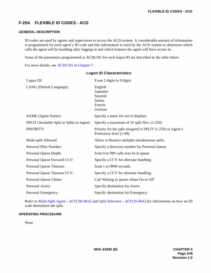
FLEXIBLE ID CODES - ACD
F-25A FLEXIBLE ID CODES - ACD
GENERAL DESCRIPTION
ID codes are used by agents and supervisors to access the ACD system. A considerable amount of informationis programmed for each agent’s ID code and this information is used by the ACD system to determine whichcalls the agent will be handling after logging in and which features the agent will have access to.
Some of the parameters programmed in ACDLOG for each logon ID are described in the table below.
For more details, see ACDLOG in Chapter 7.
Refer to Multi-Split Agent - ACD [M-90A] and Split Selection - ACD [S-98A] for information on how an IDcode determines the split.
OPERATING PROCEDURE
None
Logon ID Characteristics
Logon ID: From 2 digits to 9 digits
LANG (Default Language): EnglishJapaneseSpanishItalianFrenchGerman
NAME (Agent Name): Specify a name for use in displays
SPLIT (Available Split or Splits to logon): Specify a maximum of 16 split Nos. (1-250)
PRIORITY: Priority for the split assigned in SPLIT (1-250) or Agent’s Preference level (1-99)
Multi-split Allowed: Allow or Restrict multiple simultaneous splits
Personal Pilot Number: Specify a directory number for Personal Queue
Personal Queue Depth: from 0 to 999 calls may be in queue
Personal Queue Forward CCV: Specify a CCV for alternate handling
Personal Queue Timeout: from 1 to 9999 seconds
Personal Queue Timeout CCV: Specify a CCV for alternate handling
Personal Queue Chime: Call Waiting in queue chime On or Off
Personal Assist: Specify destination for Assist
Personal Emergency: Specify destination for Emergency
NDA-24282 (E) CHAPTER 5Page 249
Revision 1.0

FLEXIBLE ID CODES - ACD
SERVICE CONDITIONS
1. The maximum length for an ID code is nine digits, and only the digits “0” through “9” are allowed.
2. Leading zeros are permitted, but are not meaningful, in logon ID codes. For example, “0017” is acceptable;however, this code is identical to the code “17”.
3. Each split determines whether ID codes are required for access to the ACD system.
4. An ID code can only be assigned once in the ACD system regardless of which tenant the ID code is used for.
5. An ID code can only be used in the tenant in which it is assigned.
6. An ID code can only be used at one position at any given time. Multiple logons with the same ID code arenot permitted.
PROGRAMMING
ACDLOG
CHAPTER 5 NDA-24282 (E)Page 250Revision 1.0

HOLIDAY SCHEDULING - ACD
H-20A HOLIDAY SCHEDULING - ACD
GENERAL DESCRIPTION
Holidays may be programmed up to 365 days in advance. On a holiday, special call routing is in effect for up toeight time-of-day changes. Three different holiday schedules, one of which is used on any particular holiday,may be programmed for each tenant.
OPERATING PROCEDURE
See Time of Day/Week Routing - ACD [T-50A].
SERVICE CONDITIONS
1. Holiday schedule routing takes place only for those pilot numbers which route to week routing. If a pilotnumber routes directly to a Call Control Vector (CCV), its routing is not affected on a holiday even ifholiday routing has been programmed.
2. All incoming ACD traffic must follow the same routing (CCV handling) on a holiday.
PROGRAMMING
Refer to Assignment of ACD Holiday Schedule in Chapter 7.
NDA-24282 (E) CHAPTER 5Page 251
Revision 1.0

HOT SPLIT - ACD
H-31A HOT SPLIT - ACD
GENERAL DESCRIPTION
This feature was designed to accommodate “Automatic” agents of “Hot” agents. That is to say, agents who neverlog on, never log off and never take breaks. As soon as the ACD is online these “agents” are automaticallylogged on to the ACD and placed in the Ready Mode to take incoming calls. Actually, these agents are moreaccurately described as “machines” because the feature was intended for use with answering machines, dictationmachines, voice mail machines, etc.
The feature is named “Hot Split” because all members of the split must be automatic agents. There cannot be amixture of standard agent positions and hot agent positions in the same split.
Due to the nature of the equipment expected to be used for this feature it was designed to accommodate onlyanalog station equipment, or TEC = 3 for those familiar with PBX database assignments. Dterm stations inparticular cannot be used for members of a Hot Split. A member of a Hot Split is called a Hot Position.
OPERATING PROCEDURE
1. A Hot Position is idle and, therefore, in the Ready Mode. This station is the only assigned member of aparticular Hot Split. Let’s say it is an answering machine.
2. A call arrives to the Pilot Number for this Hot Split and immediately rings the Ready “agent”.
3. The “agent” (answering machine) automatically answers and does what answering machines do.Meanwhile, another call arrives for the Hot Split and is placed in queue.
4. The Hot Split is programmed for 15 seconds of After Call Work Mode Timeout. This allows the answeringmachine sufficient time to rewind or reset before the next call rings through.
5. The first caller hangs up. The “agent” enters After Call Work Mode for 15 seconds.
6. After 15 seconds the Hot Position is automatically placed in the Ready Mode and since a caller is waitingin queue it immediately rings the position.
7. The Hot Position (answering machine) answers the next call.
SERVICE CONDITIONS
1. A Hot Position is allowed to go off-hook and originate outgoing calls. It will be placed in a Break Modefor incoming ACD calls until it goes onhook.
2. Hot Positions are assumed to be in the Ready Mode upon ACD startup. If, in fact, the position is offhookand busy the ACD will make only one attempt to connect a call and then, upon noticing its busy status, willcorrectly mark the position as Unavailable and wait for its onhook.
CHAPTER 5 NDA-24282 (E)Page 252Revision 1.0

HOT SPLIT - ACD
PROGRAMMING
Step 1: ACDPSNLINE NUMBERS = ACD and PBX are the sameANALOG AGENT POSITION = No
Step 2: ACDSPLHOT SPLIT = Yes
NDA-24282 (E) CHAPTER 5Page 253
Revision 1.0

INFOLINK DATA MESSAGES - ACD
I-99A INFOLINK DATA MESSAGES - ACD
GENERAL DESCRIPTION
Infolink Data Messages provides a two-way communications link between the ACD and external computerequipment. Typical examples of external computer equipment includes but is not limited to:
• Mini and Mainframe Host Computers (IBM, DEC, Honeywell, Borroughs, Hewlett Packard)
• Desktop Workstations (Sun, IBM, Hewlett Packard, DEC)
• Personal Computers (IBM, Compaq, Dell, Gateway, AST, et.al.)
• Interactive Voice Response (IVR) systems (Centigram, Periphonics, InterVoice, Syntellect)
The first three categories are obvious examples of computer equipment but what about the fourth? The Infolinkmessage set was specifically designed to support features which are best performed by IVR equipment inaddition to several obvious applications which can be done from a host computer. IVRs can provide customizedannouncements, collect digits (account numbers, billing reference codes, etc.) from customers and provide voicemenuing, “Press ‘1’ for Sales, ‘2’ for Service or ‘3’ for Billing Inquiry”.
Three message sets have been designed for Infolink. External computers may use as little or as much of the datafrom any of the three sets as needed in order to implement their application. Unnecessary messages may beturned off to reduce transmission bandwidth. Just as there are many words which can be derived using the 26letters of the alphabet there are also many applications which can be invented using the messages available inthe Infolink message sets. We can guess what some of the obvious applications might be but there is no way topredict how far developers can go given the information available from Infolink.
Some of the possible applications which Infolink clients could perform include:
• Agent Screen Pop-Up
• Agent Screen Correlation and Screen Transfer
• Outbound Calling Campaigns
• Electronic Call Transfer
• Customized Announcements
• Host Directed Routing - Host Directed Priority Changes
• Customer Callback
• Predictive Dialing Enhancements
• Phone-In-A-Drawer
• Position In Queue Announcements
• Estimated Time To Answer Announcements
• Leave A Message vs. Stay In Queue Options
CHAPTER 5 NDA-24282 (E)Page 254Revision 1.0

INFOLINK DATA MESSAGES - ACD
The following tables lay out the names of the messages currently available:
Inbound Messages from Infolink Client to ACD
Tag Message Description
IA Dialed digits
IB Manage Call
IC Split Status/Caller Status Request
ID Announcement Request
IE Outbound Call Request
IF Route Call Request
IG Call Manipulation Request
IH State Change Request
IL Message Subscription
Outbound Messages from ACD to Infolink Client
Tag Message Description
IM ANI/DNIS Information
IN Port Release
IO Play Announcement
IP Split Status Notification
IQ Incoming Call Notification
IR Report IVR Dialed Digits
IS Agent Ringing
IT Agent Answer
IU Call Disconnect
IV Call Transfer
IW Agent State Change
IX Party Acknowledgment
IY Sequence Acknowledgment
IZ Outbound Call Disposition
NDA-24282 (E) CHAPTER 5Page 255
Revision 1.0

INFOLINK DATA MESSAGES - ACD
OPERATING PROCEDURE
Depending on the usage of each application.
SERVICE CONDITIONS
1. Each feature is defined by the detail specification of each application.
2. Lower layer protocol of Infolink supports TCP/IP + DIX Ethernet Version 2.
3. Infolink Data Messages are provided to the ACD tenant programmed in ACDTN.
4. Two-way communications link is provided simultaneously.
5. One link controls one ACD tenant.
6. OAI transmission is also provided via the same link.
7. An IVR equipment may be accommodated per ACD tenant.
PROGRAMMING
Step 1: ASDTTN: Tenant number (1-10)STN: Station number of the IVR (maximum 5 digits)TEC: 1-4
Step 2: ASHUAssign the UCD group organized by the station number accommodates the IVR port
Step 3: ACDTNIVR PILOT NUMBER : IVR Pilot number for UCD service programmed in ASHU
: Outbound Answer Timer (0-60 sec.)
Step 4: ACDIVR - Assign the desired IVR port number for all station numbers to access IVR programmedin ASDTDIRECTORY NUMBER:IVR station number programmed in ASDTPORT: IVR port number (1-255)
Step 5: ACDCCV - when IVR announcement service is provided. Note 1ACTION: IVR ANNOUNCEMENT: Note 2ARGUMENT: IVR announcement equipment number (1-99) Note 3
Announcement ID for announcement order via Infolink to the IVR
Note 1: When this command data has already been programmed for OAI features, it is not necessary to programthe data again.
Note 2: It is not necessary to program a Pause step after the IVR Announcement.
Note 3: The announcement number varies depending on each IVR Specifications.
CHAPTER 5 NDA-24282 (E)Page 256Revision 1.0

LOGON/LOGOFF POSITION - ACD
L-19A LOGON/LOGOFF POSITION - ACD
GENERAL DESCRIPTION
Access to the ACD system is controlled either with or without logon ID codes. A logon ID code is used toidentify individual agents or supervisors, to the ACD, for statistics gathering purposes. An agent is onlypermitted to be logged onto the system at one position at a time. Flexible ID Codes can be employed to log ontothe ACD system. Refer to Flexible ID Codes - ACD [F-25A] for related information.
OPERATING PROCEDURE
Logon Procedure:
This procedure varies depending on whether or not logon ID codes are used. The cases are described separately.
1. When logon ID codes are used:
a. The display shows VACANT.
b. The agent presses the LOGON key. The display shows LOGON ID?.
c. The agent enters a logon ID code, using the DTMF keypad, and presses the “#” key after the logon IDcode is entered.
d. If an invalid logon ID code is entered, the display returns to LOGON ID? and the agent must enter acorrect logon ID.
e. If the entered logon ID code is currently in use, the display briefly shows ID IN USE and then returnsto LOGON ID?.
f. If a valid logon ID code is entered, the LOGON lamp is lit, a greeting is provided, and the split theuser logged onto is displayed.
g. The console is placed in the Work mode with the Manual/Auto answer mode set to the split’s default.
h. The WORK key must be pressed before the agent can begin taking calls.
2. When logon ID codes are not used:
a. The display shows VACANT.
b. The agent presses the LOGON key; the LOGON lamp is turned on, a greeting is provided, and the splitthe user logged onto is displayed.
c. The console is placed in the Work mode with the Manual/Auto answer mode set to the split’s default.
d. The WORK key must be pressed before the agent can begin taking calls.
Logoff Procedure (with or without ID codes):
1. The agent or supervisor may log off the system while in Break mode, Work mode, or while ready to takecalls.
2. The agent presses the LOGON key at this time. Several displays will cycle on the display for four secondseach:
a. A farewell greeting; for example, GOODBYE RENEE.
NDA-24282 (E) CHAPTER 5Page 257
Revision 1.0

LOGON/LOGOFF POSITION - ACD
b. The time since logon in hours, minutes, and seconds; for example, SHIFT 6:38:08.
c. The number of incoming calls handled; for example, ACD CALLS 138.
d. If any calls were handled, the average time spent with each call in minutes and seconds; for example,AVG TALK 1:30.
e. The cumulative amount of time spent in Work mode during the shift in hours, minutes, and seconds;for example, WORK 2:07:25.
f. The cumulative amount of time spent in Break mode during the shift in hours, minutes, and seconds;for example, BREAK 1:02:41.
g. Finally, the display shows VACANT.
SERVICE CONDITIONS
1. When a vacant position displays R.I.P. (Reset In Progress), it indicates that the system is unable tocommunicate with the telephone instrument. If the LOGON key is pressed and the connection isestablished, the display will show VACANT within five seconds. If the connection cannot be established,R.I.P. will continue to be displayed.
PROGRAMMING
[When ID code is used]
Step 1: ACDSPL - Set the ID code is required to logon for each split.
Step 2: ACDLOG - Assign the ID code to logonLOGON ID: (9 digits maximum)
Note: “0” is not recognized as the first digit.
AGENT NAME: Logon ID name (14 characters at the maximum)ABBR NAME: Abbreviated ID code name (5 digits maximum)
[When ID code is not used]
Step 1: ACDSPL - Set the ID code is not necessary to logon for each split.
CHAPTER 5 NDA-24282 (E)Page 258Revision 1.0

LANGUAGE DEFAULT - ACD
L-48A LANGUAGE DEFAULT - ACD
GENERAL DESCRIPTION
This feature allows the selection of a language, applicable to an entire tenant, for use in messages displayed atpositions where an agent is not logged onto the ACD system. The following are examples of messages that willappear in the selected language:
1. The VACANT message, displayed when an agent is not logged on at the position;
2. The messages used during the logon procedure, such as LOGON ID?, (if logon ID codes are used);
3. The messages giving split information (name, queue depth, time of longest waiting call) that are displayedat a vacant position when the agent presses the AUTO/MAN key.
OPERATING PROCEDURE
None
This feature is implemented through an ACD MAT command. The command data is on a tenant-wide basis.
PROGRAMMING
ACDTN DEFAULT LANGUAGE: English
JapaneseSpanishItalianFrenchGerman
NDA-24282 (E) CHAPTER 5Page 259
Revision 1.0

LOGOFF WARNING - ACD
L-92A LOGOFF WARNING - ACD
GENERAL DESCRIPTION
This feature is programmed on a per-split basis via the ACDSPL MAT command. When a split is marked forLogoff Warning agents will receive the display “LOGOFF WARNING” for a few seconds if they try to logoffwhile there are still calls in queue. In order to actually logoff the agent must press the Logoff Key a second timeafter having received the warning message. In other words, the warning message is intended to encourage theagent to continue taking phone calls and, in fact, the agent remains logged on if the key is pressed only one time.
A value is set for the Logoff Warning feature from 1 to 9 or ALL. The value 1~9 describes the maximum numberof agents still logged onto the split when the warning is given. If the setting is at 5 then only the last five agentsto logoff from the split will be given the warning message.
The “LOGOFF WARNING” display is shown only when the number of callers waiting in queue for the agent’ssplit is greater than or equal to the number of agents still logged on in addition to the value set for LogoffWarning. That is, if the setting is at 5 and there are five agents logged on but only three calls are in queue thenan agent will be allowed to logoff and will not receive the warning message. In fact, two agents may logoff andneither will receive the message. However, when there are only three agents remaining and three calls in queue,if one of those agents attempts to logoff the warning will be provided.
SERVICE CONDITIONS
1. For multi-split agents the logoff warning is calculated for each split that the agent is a member. If any splitfalls into the logoff with warning threshold then the warning will be provided and the agent’s logoff will berestricted. No indication is given as to which split or splits has remaining calls to be answered.
2. When an agent wishes to logoff when Logoff Warning is enabled it will be required that the agent press theLOGON/LOGOFF KEY two times in succession (no intervening keypresses) and that there must be at leasta 2 second pause between the two keypresses.
This should ensure that the agent was given an opportunity to see the “ LOGOFF WARNING” display andhas chosen to ignore it and logoff anyway.
PROGRAMMING
ACDSPL -
LOGOFF WARNING CRITERIA: Assign the threshold value (necessary number of agents logged onto thesplit) for LOGOFF WARNING.0 = LOGOFF WARNING is out of service1-9 = Maximum number of agents to be logged onALL = Number of agents equal to or less than the number of calls in queue
CHAPTER 5 NDA-24282 (E)Page 260Revision 1.0

MONITORING - ACD SUPERVISOR - ACD
M-28A MONITORING - ACD SUPERVISOR - ACD
GENERAL DESCRIPTION
This feature allows the supervisor to select an agent position and to monitor the calls on both the ACD line andthe non-ACD line at that position. The agent and calling party are not aware that their call is being monitored.As the agent concludes one call and begins another, switches from one line to another, or transfers, thesupervisor’s monitor is applied to the current call. If both lines are idle when the monitoring is established, thesupervisor will hear quiet tone until the agent either answers a call on one of the lines or places a call from thenon-ACD line. At that time, the supervisor will be able to hear both parties.
OPERATING PROCEDURE
Monitoring an agent’s position:
1. While in Work mode, Break mode, or Ready mode, the supervisor presses the MON/BARGE key and thedisplay shows MONITOR NUMBER?.
2. The supervisor enters either the ID code of the agent or a “0” followed by the extension number of theposition the supervisor wishes to monitor and “#”. For example, to monitor the agent whose ID code is“101” and who is at extension “4301”, the supervisor presses either 101# or 04301#. Either a PBX or ACDextension can be used.
3. If the ID code or extension number is valid and the agent has a call in progress on either line, the MON/BARGE lamp will flash and the supervisor will hear a Zip Tone before silently listening in on the agent’scall.
4. If no ACD call is in progress, the MON/BARGE lamp will be steadily lit and the supervisor will hearnothing.
5. As calls are handled by the agent, the supervisor will alternate between the two states described previously.
6. If the agent transfers to a third party, the supervisor will hear the conversation between the agent and thethird party. When the agent returns to the original caller, the supervisor will again hear the agent and theoriginal caller.
7. While monitoring a conversation, the monitor function is terminated either by releasing or by pressing theMON/BARGE key. The ACD system will respond by displaying the prompt BARGE? (Note 1). To barge,the supervisor enters 1#. To exit from the monitor mode and return to the previous mode, the supervisorenters # or presses the MON/BARGE key again.
8. While listening the quiet tone, the monitor function is terminated by pressing the MON/BARGE key once.
Note: To use this feature, the supervisor must be off-hook and must not use the SPEAKER key of a Dterm to monitoran agent. If the SPEAKER key is used, the SPEAKER lamp on the supervisor’s Dterm is extinguished whenthe call is released by either the agent or the ACD calling party. If the supervisor presses the SPEAKERkey before another call is routed to that agent, monitoring will continue. If the agent receives another callbefore the supervisor’s SPEAKER key is pressed, the monitor function is terminated.
Note 1: After supervisor presses 1 # A, three-party conference is established.
NDA-24282 (E) CHAPTER 5Page 261
Revision 1.0

MONITORING - ACD SUPERVISOR - ACD
Barging in on the monitored call:
1. Set up the monitor function as described in the preceding section.
2. While the agent is engaged in a conversation on the ACD line and the supervisor is monitoring, thesupervisor may press the MON/BARGE key. The ACD system will respond by displaying the promptBARGE?. To barge, the supervisor enters 1#. A three-way conference connection is now established.
3. Intrusion tones are provided to both the agent and the calling party prior to the conference connection, andthe supervisor’s MON/BARGE lamp will wink.
4. At this time one of two things is likely to happen:
a. The supervisor may press the RELEASE key or the MON/BARGE key to terminate the conferenceconnection (barge) and return to the monitor connection.
b. The agent may press the RELEASE key and relinquish control of the call to the supervisor. In this case,the supervisor will continue to talk to the incoming caller until the call is completed, either by the su-pervisor pressing the RELEASE key or the MON/BARGE key, or by the caller releasing first. The su-pervisor will then return to a monitor connection, either listening to the agent on a new call, or quiettone if there is no call.
SERVICE CONDITIONS
1. While monitoring or barging, the supervisor can display the identification of the original ACD call and thequeue depth by pressing the LOGON key. Please see Calling Party Identification - ACD [C-70A] foradditional information.
2. During three-party calls such as transfers and conferences, the supervisor will not be able to barge in, butwill continue monitoring the agent and one of the other two parties. The monitoring will be updated tofollow assist calls.
3. A supervisor can only monitor agents that are currently logged onto the ACD system. If a supervisor bargesinto a monitored call, and the agent releases and logs off, the supervisor will return to the previous mode atthe completion of the call.
4. While monitoring an agent’s PBX (non-ACD) line, the supervisor cannot barge into the conversation.Barges can only be done while monitoring ACD lines.
5. While the supervisor is monitoring, if the agent being monitored begins an emergency request, thesupervisor will be released. This allows the supervisor to answer the emergency if necessary.
6. When requesting an agent to monitor, if the agent is not logged on, is on an emergency call, or is beingmonitored by another supervisor, the supervisor will be prompted again.
7. This feature is restricted to ACD positions. There is no capability to monitor voice connections, conductedby non-ACD users, among the remaining (non ACD) station equipment connected to the switch. The intentof this feature is to provide a secure, ACD-only, performance appraisal function.
8. If the agent places a call on hold or performs switch hook flash and is reconnected with the call, thesupervisory position will release from monitoring for a moment. But the system will automaticallyreconnect the monitor again.
CHAPTER 5 NDA-24282 (E)Page 262Revision 1.0

MONITORING - ACD SUPERVISOR - ACD
CAUTION: The use of a monitoring device to eavesdrop may be illegal under certain circumstances and laws. Legaladvice should be sought before implementing any practice that monitors a telephone conversation.Some federal and state laws require the monitoring party to use beep tones, to notify all parties to thetelephone conversation, or to obtain the consent of all parties to the telephone conversation. Some ofthese laws incorporate strict penalties.
PROGRAMMING
AKYD - Assign MON/BARGE function to a feature key.
NDA-24282 (E) CHAPTER 5Page 263
Revision 1.0

MULTIPLE CUSTOMER GROUPS - ACD
M-29A MULTIPLE CUSTOMER GROUPS - ACD
GENERAL DESCRIPTION
The system can be arranged to independently service more than one ACD customer (tenant). Ideally allcomponents of the ACD system should be duplicated for each tenant but in reality some components can beshared.
Using multiple tenants in an attempt to circumvent limitations imposed at a per-tenant level does not work sincetoo many components end up being shared. Tenant limitation exists for a reason often related to software designconsiderations. Assigning a second tenant to take advantage of a tenant parameter may appear to work at firstbut blending all the other components of a multi-tenant ACD can present several difficulties.
OPERATING PROCEDURE
No manual operation is required.
SERVICE CONDITIONS
1. Multiple tenants were designed to serve separate groups within one ACD system. Each group should haveseparate telephone facilities, MIS systems and personnel.
2. Attempts to share resources will typically result in inaccurate statistics since calls which cross tenantboundaries cannot be adequately tracked by either system.
PROGRAMMING
For consideration of the ACD tenant, see Assignment of ACD Tenant Data in Chapter 7.
Step 1: ASYD- Assign the tenant development table data.Separate or Common Tenant Data table development for the respective commands.0/1=Separate/Common
Note: When data “1”is assigned, data must be assigned for Tenant 1 (TN=1) in the respective commands.
SYS1, INDEX92,b0: System Data-2 (“ASYD” command)b1: Special Access Code Data (“ASPA”,“AASP”,“AGSP” commands)b2: Numbering Plan Data (“ANPD”, “AANP”, “AGNP’ commands)b3: Station Data (“ASDT”, “AAST”, “AGST”, “ALDN”, “ASAT” commands)b4: Route Restriction Class Data (“ARSC” command)b5: Call Forwarding Restriction Data (“ACFR” command)
SYS1, INDEX93,b0: Service Feature Restriction class Data (“ASFC” command)b1: Call Forwarding Data (“ACFO” command)b2: TAS Data (“ATAS” command)b3: Speed Calling Data (“ASPD” command)b4: Route and Selection Translation Data (OG, Tandem) (“ASTP”, “AFRS” commands)b5: Route and Selection Translation Data (IC) (“ASTP”, “AFRS” commands)
CHAPTER 5 NDA-24282 (E)Page 264Revision 1.0

MULTIPLE CUSTOMER GROUPS - ACD
b6: Maximum Necessary Digit Data (“AMND” command)b7: Announcement Equipment Data (“AAED” command)
SYS1, INDEX94,b0: Tenant Restriction Class Data (“ATNR” command)b1: EPN Facility Restriction Data (“AEFR” command)b2: Primary Call Restriction Data (“APCR” command)b3: Authorization Code Data (“AATC” command)
Step 2: ACDTN- Assign the ACD tenant data.TN: ACD tenant (1-10)NAME: Name corresponding to the ACD tenant data (max. 20 digits)SPLITS: Maximum Split for Tenant (1-250)DEFAULT LAUGUAGE
EnglishJapaneseSpanishItalianFrenchGerman
OPERATOR ACCESS CODE: Enter the operator access code programmed in the ASPA orASPAN
IVR PILOT NUMBER: Number to access IVR directory numbers used by ACDOUTBOUND ANSWER TIME: Time (in seconds) after which an outbound call is assumed to have
been answered.AGENT PERSONAL QUEUE: Personal Announcement Number (0-58) or SPACE: feature not
usedPRIORITY: Priority to use for split queuing after overflow or call forwarding
(1 to 255) orSPACE: feature not used.
NDA-24282 (E) CHAPTER 5Page 265
Revision 1.0

MULTIPLE SUPERVISOR GROUPS (SPLITS) - ACD
M-79A MULTIPLE SUPERVISOR GROUPS (SPLITS) - ACD
GENERAL DESCRIPTION
Multiple supervisors can be grouped together to form a split when it is necessary for more than one supervisorto serve a split of agents. Assistance and emergency requests can be routed to a split of supervisors, but a splitof supervisors does not normally receive incoming call traffic unless it has been programmed as a secondarysplit to be queued to in a Call Control Vector (CCV). Refer to Call Control Vector - ACD [C-108A] for moredetailed information. All aspects of an agent split, such as call waiting indication and queuing, also apply to asplit of supervisors.
OPERATING PROCEDURE
For additional reading please see the note for “The Supervisor Concept” in Splits - ACD [S-91A].
SERVICE CONDITIONS
1. This feature is released since the PBX software Series 7400 and the ACD software R3.
2. Assistance and emergency calls with this feature can not be taken by the supervisor in Work Mode or BreakMode (Assistance and emergency call to a individual supervisor can be taken by supervisors in thosemodes).
3. The followings are differences between assistance/emergency requests to an individual supervisor andthose to a split of supervisors. See Assistance - ACD Agent - ACD [A-34A] and Emergency/Recorder -ACD [E-6A] for more details,
4. CCV data programmed for a pilot number of a split of supervisors as the destination of Assistance call orEmergency call is as follows. See Assignment of ACD CCV Data in Chapter 7.
• STEPn Queue Assign, Conditional Queue Assign, Goto
• STEPn+1 Pause (Valid for CCV data for Assistance only)
• STEPn+2 End CCV
5. Since DAY/NIGHT CLASS OF SERVICE [D-15] cannot be used for the split of supervisors, do not set thedata that ACD call excluding Assistance and Emergency calls terminated to the split directly.
6. When using dictation trunk for EMERGENCY/RECORDER, recording starts from the moment the callterminates to the supervisory position (It is not recorded while the call is in queue).
DestinationService
Individual Supervisor Split of Supervisor
Assistance-ACD Agent Assistance call terminates to PBX line for the supervisor
Assistance call terminates to the pilot number of the split
Emergency/Recorder Emergency call can be distributed to the supervisor in Work Mode/Break Mode.
Emergency call can not be distributed to the supervisor in Work Mode/Break Mode.
CHAPTER 5 NDA-24282 (E)Page 266Revision 1.0

MULTIPLE SUPERVISOR GROUPS (SPLITS) - ACD
PROGRAMMING
Step 1: ACDSPL - Assign assistance and emergency request destinations per split.ASSIST - pilot number of a split of supervisorsEMERGENCY - pilot number of a split of supervisors
Step 2: ACDLOG - Assign assistance and emergency request destinations per ID code.ASSIST REQUEST - pilot number of a split of supervisorsEMERGENCY REQUEST -pilot number of a split of supervisors
NDA-24282 (E) CHAPTER 5Page 267
Revision 1.0

MIS OPERATOR SELECTION - ACD
M-88A MIS OPERATOR SELECTION - ACD
GENERAL DESCRIPTION
This feature permits the selection of an access code for an operator, for an entire tenant. Certain MIS changecommands permit the operator to be selected as the destination when routing ACD calls.
In the extreme case where the ACD traffic has exhausted all available call records (too many simultaneous ACDcalls either connected or in queue) all new incoming ACD traffic will be diverted to the code specified for theMIS Operator Selection. Once diverted the caller should be encouraged to call back at a later time when theACD system is not so congested.
OPERATING PROCEDURE
This feature is implemented through an ACD MAT command. The command data is on a tenant-wide basis.
PROGRAMMING
ACDTN - OPE NO: Operator access code (Maximum 5 digits)
CHAPTER 5 NDA-24282 (E)Page 268Revision 1.0

MONITOR ME - ACD
M-89A MONITOR ME - ACD
GENERAL DESCRIPTION
During an ACD call, an agent can request to be monitored by a specific supervisor. When the agent presses theASSIST key or presses the TALLY key and dials 006#, a monitor request is sent to the designated supervisor.Upon answering, the supervisor is in a silent monitor connection listening to the agent and the calling party.
The number (personal assist request number) associated with the supervisor is programmable for each agent.
The ASSIST key and the personal assist request number can be used for either the MONITOR ME feature orthe ASSISTANCE - ACD AGENT feature. The choice is made for each split. Regardless of which feature thekey and number are dedicated to, if an agent personal assist number and a split assist request number are bothdefined, the personal assist request number will always be used. If an agent is in multi-split mode and a personalassist request number is defined, the quantity of splits which have an assist request number defined ismeaningless; the personal assist request number will be applied. Please refer to Multi-Split Agent - ACD[M-90A] for more information.
OPERATING PROCEDURE
The following example illustrates how the feature functions.
1. An agent is logged onto a position; the extension is 4281.
2. The agent requests to be monitored by pressing the ASSIST key.
3. While the supervisor’s position is being rung, the agent and the calling party remain connected and cancontinue to converse.
4. The ASSIST lamp at the agent’s position is lit, and the display shows the individual supervisor’s name. Anexample of the display is MONITOR JAMES.
5. When the destination supervisor is idle, the MON/BARGE lamp at the destination supervisor’s position islit and the display provides the extension of the agent who is requesting the monitor activity and the trunktype and number to which the agent is connected. The display appears when the monitor request is ringingand when it is answered.
6. The supervisor answers the request and begins monitoring the agent and the calling party.
7. The ASSIST lamp at the agent’s position starts to flash and the display changes to MONITOR ANSWERED.
8. At this point, the supervisor is able to release the call or to barge. The latter option results in a three-waycall involving the supervisor, the agent, and the calling party. To initiate the barge, the supervisor pressesthe MON/BARGE key; the ACD system responds with a BARGE? prompt. The supervisor can enter 1# toaffirm the barge, at which point the agent and calling party are sent an intrusion tone. The supervisor cancancel the monitor activity by either pressing the MON/BARGE key or by entering #.
NDA-24282 (E) CHAPTER 5Page 269
Revision 1.0

MONITOR ME - ACD
SERVICE CONDITIONS
1. This service requires the three-conference trunk.
2. During the barge (three-way conversation), any of the three parties may release themselves from the call;the other two parties remain connected.
3. The monitor activity, which is silent, is automatically canceled if the agent transfers to another party.
4. If the connection between the calling party and the agent is terminated prior to the supervisor’s response tothe monitor request, the request is automatically canceled.
5. While the supervisory position handles the ACD call, the LCD display for the service indication for“MONITOR ME” (see OPERATING PROCEDURE for details of indication) and the chime informs thesupervisory position with the request. On the LCD of agent position, “MONITOR BUSY” is displayed.
6. When the supervisory position is logged off or in BREAK mode, the service indication of “MONITORVACANT” or “MONITOR BREAK” is displayed on the agent position’s LCD at each time. However, thesupervisor can not find the service request via its LCD display.
CAUTION: The use of a monitoring device to eavesdrop may be illegal under certain circumstances and laws. Legaladvice should be sought before implementing any practice that monitors a telephone conversation.Some federal and state laws require the monitoring party to use beep tones, to notify all parties to thetelephone conversation, or to obtain the consent of all parties to the telephone conversation. Some ofthese laws incorporate strict penalties.
PROGRAMMING
Step 1: ACDSPL - Assign the ACD line’s number of the supervisory position as the assistance call’s desti-nation and the service activated with ASSIST key.ASSIST: ACD line of the supervisory positionASSIST Key or MONITOR ME
Step 2: AKYD - Apply “ASSIST” key to the function key.KYN = 7 (as an example)KYI = 1FKY = 41 (ASSIST)
CHAPTER 5 NDA-24282 (E)Page 270Revision 1.0

MULTI-SPLIT AGENT - ACD
M-90A MULTI-SPLIT AGENT - ACD
GENERAL DESCRIPTION
This feature allows an individual agent to handle calls from a maximum of four (ACDP software R1 or R2)/sixteen splits (ACDP software R3). The agent’s logon ID is programmed to specify whether the agent ispermitted to handle calls from a single split (single-split mode) or from multiple splits (multi-split mode).
The agent’s logon ID is programmed to specify which splits the agent can service. The logon ID permits one tofour/sixteen specific splits to be listed, or access to any split to be indicated. If specific splits are listed, then apriority (or preference level) is assigned to each split. There are 99 priority levels (1>99); splits can be assignedthe same level.
An agent who is servicing multiple splits will have calls assigned based on a two-level algorithm. The first levelof assignment is based on the priorities of the splits. Calls from the split with the highest priority will always beconnected before calls from splits with lower priorities. The second level of assignment is the amount of timethat the longest waiting call has been in queue. This level is only used if two or more splits have the samepriority. If splits have the same priority, then the call with the longest time in queue will always be connectedbefore calls that have spent less time in queue. The following examples, where an agent is servicing four queues,illustrate the two-level algorithm.
In this case, the call in Split 1 will be connected to the agent. Split 1 has the highest priority of the splits that theagent is serving. Thus, the fact that Split 1 has the fewest calls and the call with the shortest time in queue is nota consideration.
In this example, the next call that is connected to the agent will be the longest waiting call from Split 2. The splitwith the highest priority, Split 1, does not have any calls in queue. Split 2 and Split 3 have the same (and nexthighest) priority. Thus, the longest waiting call will be selected, and that call resides in Split 2 (60 seconds asopposed to 35 seconds).
Table 5-3 Call Distribution Algorithm - I
SPLITNUMBER
PRIORITY LEVEL
CALLS IN QUEUE
LONGEST WAITING CALL
1 1 1 15 seconds
2 2 4 45 seconds
3 2 7 20 seconds
4 3 3 50 seconds
Table 5-4 Call Distribution Algorithm - II
SPLITNUMBER
PRIORITY LEVEL
CALLS IN QUEUE
LONGEST WAITING CALL
1 1 0
2 2 4 60 seconds
3 2 7 35 seconds
4 3 3 65 seconds
NDA-24282 (E) CHAPTER 5Page 271
Revision 1.0

MULTI-SPLIT AGENT - ACD
The splits that an agent can handle are not based solely on the agent’s logon ID. A combination of three factorsdetermines which splits a specific agent, at a specific position, can handle. These factors and their associatedvariables are:
1. The splits allowed by the agent’s logon ID, which can be a list of one to four/sixteen specific splits, or anysplit.
2. The splits allowed by the position, which can be one specific split or any split.
3. The split mode allowed by the agent’s logon ID, which can be single-split or multi-split.
The ensuing paragraphs describe the scenarios associated with each possible combination of the three factors.While examining these scenarios, it would be beneficial to reference Table 5-5. The table’s horizontal axisdescribes the agent’s logon ID (split mode and allowed splits) and the vertical axis describes the position’sallowed splits. The intersection presents the split mode in which the agent will operate and the split or splits theagent will service (indicated with lower-case letters in parentheses).
The single-split mode scenarios will be examined first.
An agent, in single-split mode, whose logon ID lists one to four/sixteen allowable splits can log on to a positionwith a single specified split (which matches one of the agent’s logon ID splits) or a position with any splitallowed. As an example, an agent’s logon ID specifies the splits 2, 5, 8 and 12. The agent can log on at a positionthat specifies one of those splits (2, 5, 8 or 12). Alternatively, the agent can log on to a position that allows anysplit. During the logon procedure, the splits in the logon ID list are displayed sequentially. The agent indicatesthe single split of choice by entering 1#; entering # indicates that this is not the split of choice. The agent’s splitdefaults, such as the after-call mode and the answer mode, will be the defaults associated with the single splitthat is chosen.
An agent, in single-split mode, whose logon ID permits any split can only logon at a position that permits asingle specified split. The agent will take calls from the single split and the agent’s split defaults will be thedefaults associated with that split.
An agent, in single-split mode, whose logon ID allows any split is not permitted to log on at a position thatallows any split. This combination would force the ACD system to begin to sequentially prompt the agent withthe name of every split in the system, until the agent selected the single split in which they wish to work. Thisis not an effective use of agents’ time.
The multi-split mode scenarios will now be examined.
An agent, in multi-split mode, is not permitted to have a logon ID which allows any split. This combinationwould force the ACD system to begin to sequentially prompt the agent with the name of every split in thesystem, until the agent selected the splits in which they wish to work. As in the previous case, this is not aneffective use of agents’ time.
If taken together, the last scenario of the single-split mode (an agent’s logon ID allows any split, the agent is notpermitted to log on at a position which allows any split), and the first scenario of the multi-split mode (an agent’slogon ID which allows any split is not permitted), the following ACD condition is the result. If an agent’s logonID allows any split, then the agent will automatically be put into single-split mode and will not be allowed tolog on at a position which allows any split.
CHAPTER 5 NDA-24282 (E)Page 272Revision 1.0

MULTI-SPLIT AGENT - ACD
An agent, in multi-split mode, whose logon ID allows a list of specific splits can log on at a position that allowsa single specified split (where the split matches one of the allowed splits in the agent’s logon ID list) or at aposition that allows any split. In both cases, the agent will automatically be allowed to handle calls from everysplit in the agent’s logon ID list. As an example, the agent’s logon ID list allows splits 2, 5 and 8. The agent logson at a position that allows Split 5. The agent will be allowed to handle calls from splits 2, 5 and 8. The sameagent logs on at a position that allows any split. The agent will be allowed to handle calls from splits 2, 5 and 8.The agent’s split defaults, such as the after-call mode and the answer mode, will be the defaults associated withthe agent’s logon ID attribute split. The attribute split is the first split in the list of allowable splits.
The CW lamp (Call Waiting), for an agent in multi-split mode, reflects the status of every split that the agent isservicing. The CW lamp serves as a visual indication for changes in the depth of each split queue. Thresholdsfor each split queue, based on the quantity of calls in the split queue, are programmed to force the CW lamp tolight or flash. There are two separate thresholds. Please refer to Call Waiting Indication - LCD Display/CWLamp - ACD [C-68A] for related information. Since the CW lamp is related to multiple splits, the lamp is usedto indicate the most “severe” case at any given time. For example, the CW lamp reflects the status of the firstsplit that has either reached a threshold, the first to reach a higher threshold (flashing), or the status of the splitwhich has exceeded a threshold by the greatest amount of calls.
The NIGHT lamp, for an agent in multi-split mode, reflects the night mode of the attribute split. The agent isallowed to put the attribute split into Night mode, or remove the attribute split from Night mode.
Table below summarizes the valid combinations of an agent’s split mode, the splits allowed to the agent, andthe splits allowed to the position. Recall that a logon ID which allows the agent to operate in multi-split modeand service any split is not permitted. The intersection of the rows and columns presents the split mode in whichthe agent will operate and the split or splits the agent will service (indicated with lower-case letters inparentheses; (a), (b), (c), (d)).
Table 5-5 Valid Logon ID/Position Combinations
Agent’s Logon ID-ACDLOGSplit Mode - single split or multi split:MULTS=0/1Allowed Splits - List (a, b, c, d) or Any Split:SPLIT
Position’s Allowed Splits-ACDPSN
Single-Split List(a, b, c, d)
Single-Split Any Split
Multi Split List(a, b, c, d)
Single (a):SPLC=1 Single (a) Single (a) Multi (a, b, c, d)
Any:SPLC=0 Single (a, b, c, d) Not Allowed Multi (a, b, c, d)
NDA-24282 (E) CHAPTER 5Page 273
Revision 1.0

MULTI-SPLIT AGENT - ACD
The splits allowed to a position or an agent can be changed by using the ACD MAT, the MIS, or a SupervisorTally-Oh Code. These changes can be implemented while agents are logged on at positions. The impact on theagent’s call handling and the agent’s ability to log on at the same position in the future are described by the twogeneral statements which follow.
1. If the changes to the splits allowed the position and/or the splits allowed the agent produce a situation whichis not a valid combination, the agent will be allowed to continue handling calls as before until the agent logsoff.
2. If the changes to the splits allowed the position and/or the splits allowed the agent produce a situation whichis not a valid combination, the agent will not be allowed to log on at the same position after the agent logsoff.
OPERATING PROCEDURE
This feature is implemented through ACD MAT assignments. The three critical areas which underpin the featureare:
1. The split mode of the agent, which is part of the agent logon ID, is programmed on an agent basis.
2. The splits that an agent can service, which is part of the agent logon ID, is programmed on an agent basis.
3. The splits allowed at a position are programmed on a position basis.
PROGRAMMING
ACDLOG - SPLIT: Split no. which an agent belongs to (1-250)
four splits - when using PBX software R4~Series 7300 and ACD software R1, R2sixteen splits - since PBX software Series 7400 and ACD software R3
PERFORMANCE: Priority order to handle ACD calls terminated to each split (1-99)When the priority is not taken, assign all “1” here.
MULTI-SPLIT: Multi Split or Single Split
CHAPTER 5 NDA-24282 (E)Page 274Revision 1.0

NIGHT SERVICE - ACD
N-12A NIGHT SERVICE - ACD
GENERAL DESCRIPTION
This feature provides alternate routing for calls destined for a particular split. When Night mode is in effect fora split and a call attempts to queue to that split, the call is routed to a programmed pilot number (night pilotnumber), used by the split, instead of being queued. At this point, the call is handled by the Call Control Vector(CCV) of the new pilot number. Refer to Call Control Vector - ACD [C-108A] for related information. Nightmode is invoked manually by pressing the NIGHT key, or automatically by the MIS.
OPERATING PROCEDURE
[Manual Change-over]
Night Mode Engage:
1. The supervisor presses the NIGHT key while logged onto the ACD system.
2. ENTER NIGHT/FWD? is shown on the display and the agent presses 1# to confirm entering Night mode.
3. At this point, the split goes into Night mode, the NIGHT lamp is lit at all the positions in the split, andincoming calls are routed to the night pilot number programmed from the ACD Screens.
Night Mode Cancel:
1. Night mode may be canceled by pressing the NIGHT key again. EXIT NIGHT? is shown on the display andthe agent presses 1# to confirm entering Day mode.
2. At this point, the split exits night service and the NIGHT lamp is extinguished at all the positions in thesplit.
[Automatic Change-over]
Automatic change-over from Day mode to Night mode and vice versa is accomplished from the MIS system.See the manual described on the MIS functions.
Note: MIS cannot change split from day to night mode when night pilot involves a week schedule.
SERVICE CONDITIONS
1. The pilot number used for Night mode cannot contain a “*” or a “#”.
2. The pilot number for Night mode may invoke either a Week Schedule or a CCV.
3. The NIGHT lamp shows the current night status regardless of whether the night status was changedautomatically or manually.
4. When a call attempts to queue to a split using a Queue to Split instruction in a CCV and the split is in Nightmode, the Night mode routing for the split is only followed if the split is the primary split for the call. If thesplit is a secondary split, the Queue to Split instruction is skipped. A primary split is the split specified inthe first queuing instruction in a CCV. Splits specified in subsequent queuing instructions in the CCV arereferred to as secondary splits.
NDA-24282 (E) CHAPTER 5Page 275
Revision 1.0

NIGHT SERVICE - ACD
5. When a call attempts to queue to a split using the Conditional Queue to Split instruction in a CCV and thesplit is in Night mode, the Conditional Queue to Split instruction is skipped.
6. When alternate routing is required by a split, Call Forwarding - Split - ACD [C-127A] may be used toprovide a more dynamic choice of the pilot number used for the new routing.
7. When a split enters Night mode automatically, using the MIS, Call Forwarding - Split - ACD [C-127A] iscanceled.
8. For multi-split positions the NIGHT key activates night mode for the agent’s attribute split only. Theattribute split is the first split assigned for the agent’s logon ID. Refer to Multi-Split Agent - ACD [M-90A]for related information.
PROGRAMMING
Step 1: ACDPLT - ALTERNATE NIGHT CCV:INDEX: CCV index number to be routed in the night modeSTEP: CCV step number to be routed in the night mode
Step 2: ACDSPL - Assign the pilot number of the Night mode destination.DIR NUMBER NIGHT: 5 digits maximum
Step 3: AKYD - Assign “Night” key to a supervisory position when DAY/NIGHT mode is changed overby the supervisory position.
CHAPTER 5 NDA-24282 (E)Page 276Revision 1.0

NON-ACD CALL - ACD
N-14A NON-ACD CALL - ACD
GENERAL DESCRIPTION
This feature allows agents and supervisors to receive calls from and place calls to other ports in the system (e.g.,PBX stations, attendants, trunks). When and agent or supervisor position is called using their PBX directorynumber, the call appears on the PBX line provided for that purpose. The same PBX line also permits agents andsupervisors to place outgoing calls.
OPERATING PROCEDURE
The operation to place and receive calls on the PBX line is like any other PBX line with all the associatedprivileges and restrictions.
SERVICE CONDITIONS
1. The PBX line is not essential to ACD operation. Both agents and supervisors can operate without a PBXline. Agents and supervisors would only lose the ability to place non-ACD calls.
2. Direct incoming calls to PBX lines are permitted. When a call is received, or placed, on a PBX line, it istagged as a non-ACD call by the MIS.
PROGRAMMING
Refer to Assignment of ACD Position Data in Chapter 7.
NDA-24282 (E) CHAPTER 5Page 277
Revision 1.0

OVERFLOW - ACD
O-10A OVERFLOW - ACD
GENERAL DESCRIPTION
This feature allows an ACD incoming call, which queues to a split for the predetermined period, queue toanother SPLIT automatically and simultaneously. The agents capable of attendance, ther earlier connection maybe achieved.
The overflow destination can be a split, extension, announcement, IVR, trunk, attendant console, etc. "Overflow- ACD" feature indicates overflow to another split.
Operation Procedure
None
Service Conditions
1. When a call overflow to another split, the call is queued to the original split and the overflowed splitsimultaneously. The overflowed call can be overflowed again to another split. Likewise a call can be queuedonto four (4) splits simultaneously. If simultaneous queuing is not required, a queue done by overflow canbe denied (de-queued) by the office data.
2. Simple overflow (by the predetermined period) and conditional overflow are available. You can choosesimple overflow, or one kind of conditional overflow by the office data. The applicable conditionaloverflows are below:
• Queued call reaches the predetermined period and the number of queuing calls reaches the threshold (1-99)
• Queued call reaches the predetermined period and the number of vacant agents becomes the threshold(1-250)
3. When an ACD call (which is not an overflowed call) and an overflowed call are in queue, the calltermination priority can be assigned by office data. The system computes the priority of an ACD call (1-250 determined by ACDPLT) and overflowed call (1-250 determined by the ACDCCV "Up Priority"setting), the the prior party (the smaller priority number is given) to be terminated to the available agent. Ifpriority data for the calls are the same, the call termination by the FIFO orders.
CHAPTER 5 NDA-24282 (E)Page 278Revision 1.0

OVERFLOW OUTSIDE - ACD
O-19A OVERFLOW OUTSIDE - ACD
GENERAL DESCRIPTION
This feature is provided by proper programming of Call Control Vectors, specifically using the “Transfer To”instruction. See Call Control Vector - ACD [C-108A] for additional information.
NDA-24282 (E) CHAPTER 5Page 279
Revision 1.0

PRIORITY QUEUING - ACD
P-21A PRIORITY QUEUING - ACD
GENERAL DESCRIPTION
The ACD system supports 250 different queue priorities for every split. Priorities in a split queue are assignedsuch that priority “1” calls have the highest priority and priority “250” calls have the lowest priority. Calls witha higher priority will be serviced, in the order in which they were queued, before calls with a lower priority,regardless of the waiting time of the calls with a lower priority.
A particular call’s priority is determined by the following factors:
1. Call origination (incoming trunk or internal station).
2. Call transfer (by attendant or station).
3. Pilot number dialed.
4. CCV priority change steps.
OPERATING PROCEDURE
When implementing a system which will use multiple priorities for incoming callers there are several importantconcepts to keep in mind:
[HIGHEST PRIORITY CALLERS ALWAYS GO FIRST]
Callers with a higher priority are always serviced before those with lower priorities. As a result of this a lowpriority call could remain in queue forever or at least as long as higher priority calls continue to arrive. Thissituation can be rectified by proper CCV programming. After a low priority call has been in queue for someamount of time a “New Priority” step in the CCV can change a call’s priority. It should be changed to somethingat least as high as, if not higher than, the highest priority in use for other calls.
In this way a low priority caller is only penalized (kept at a low priority) for a certain amount of time after whichit will be treated similarly to the higher priority calls coming in.
[DETERMINING TRUNK CALLER PRIORITY]
The priority of an incoming trunk call is determined by checking two places.
• A priority assigned to the trunk group (route)
• A priority assigned to the pilot number dialed
The higher of these two priorities will be used for the call.
SERVICE CONDITIONS
Calls transferred into the ACD by PBX stations and calls transferred by attendants have the same priority.
CHAPTER 5 NDA-24282 (E)Page 280Revision 1.0

PRIORITY QUEUING - ACD
PROGRAMMING
Step 1: ACDTG - Assign the priority order to each ACD route.PRIORITY: Queue priority of ACD route (1-250) (1>250)
Step 2: ACDPLT - Assign the priority order for ACD calls terminated to each pilot numberTRUNK: Priority order of ACD calls from a trunk (1~250)INTERNAL: Priority order of ACD calls from a station (1~250)TRANSFER: Priority order of ACD calls to be transferred (1~250)
NDA-24282 (E) CHAPTER 5Page 281
Revision 1.0

PILOT NUMBERS - ACD
P-40A PILOT NUMBERS - ACD
GENERAL DESCRIPTION
Pilot numbers are the access codes to ACD functions. They are programmed into the PBX-side databaseaccording to the numbering plan in effect for the system. Pilot numbers do not correspond to any lineappearances, either physical or virtual, in the system. No physical equipment is required to assign a pilotnumber.
Although pilot numbers are often thought of as ringing into a particular split, pilot numbers are associated witha Call Control Vector (refer to Call Control Vector - ACD [C-108A]) which in turn controls the handling of theACD call. Since most Call Control Vectors will present a call to a split as one of their first functions, the pilotnumbers appear as if they are connecting the ACD call to a split.
An ID can be associated with a pilot number. This ID will be displayed at an agent’s position when the agentaccepts a call that entered the system via that pilot number. An example of this display is TECH SUPPORT.Refer to Calling Party Identification - ACD [C-70A]” for related information.
If an incoming ACD call enters the system through a pilot number and the receiving agent uses a pilot numberto transfer the call to an agent in another split, the transferred call will be identified by the ID associated withthe former pilot number. If an ID is not associated with the former pilot number, the call will be identified bythe ID associated with the latter pilot number. For example, an agent in Split A receives a call via a pilot numberwith an associated ID of “SERVICE”, resulting in SERVICE being displayed at the agent’s position. The agentuses a pilot number to transfer the call to Split B. Split B has an associated ID of “PARTS”. The agent whoreceives the transferred call in Split B will have PARTS n displayed at his position. If an ID was not associatedwith the original pilot number, the agent in Split B will have PARTS displayed at his position.
SERVICE CONDITIONS
Only the digits “0” to “9” may be used (“*” and “#” are not allowed) with a minimum of two digits and amaximum of five digits in each Pilot Number.
PROGRAMMING
Refer to Assignment of ACD Monitor Number in Chapter 7.
CHAPTER 5 NDA-24282 (E)Page 282Revision 1.0

PERSONAL EMERGENCY AND ASSIST - ACD
P-45A PERSONAL EMERGENCY AND ASSIST - ACD
GENERAL DESCRIPTION
This feature allows an agent to have a designated individual supervisor’s number as the destination for an assistrequest (personal assist request number) and a designated individual supervisor’s number as the destination foran emergency request (personal emergency request number). If these personal numbers are defined for an agent,then these numbers will be used instead of the emergency and assist numbers that are defined for a split. If thesepersonal numbers are not defined, then the request (emergency/assist) will be directed to the supervisor who wasdesignated for the split. In the latter case, the split is the split in which the agent received the call. This is truefor an agent working in single-split or multi-split mode. Please refer to Multi-Split Agent - ACD [M-90A] forrelated information.
OPERATING PROCEDURE
For these examples, the agent’s name will be Molly and the supervisor’s name will be Kathey.
To place a personal assistance request:
1. While on an ACD call, Molly at extension is 4302 presses the ASSIST key. The ASSIST lamp turns on andASSIST KATHEY is displayed on the agent’s position indicating whose supervisor position is receiving thecall.
2. The ACD call is placed on hold and an automatic transfer to the designated supervisor is initiated.
3. The agent hears ringback tone and the supervisor’s position is rung.
4. The assistance call will connect on the supervisor’s ACD line and the supervisor’s position will displayeither ASSIST MOLLY or ASSIST 4302, depending on whether the agent’s name is programmed with his orher logon ID. Please refer to Flexible ID Codes - ACD [F-25A] for more information.
5. After consulting with the supervisor, one of three things may occur:
a. The agent may release from the call thereby completing the transfer of the ACD call to the supervisor.
b. The supervisor may release from the call. This will reconnect the agent and the ACD call.
c. The agent may press the CONF key and invoke a three-way conference between the supervisor, theagent and the ACD calling party.
6. When either the agent or the supervisor disconnects from the assistance call, the ASSIST lamps areextinguished and the displays return to their original status.
To cancel a personal assistance request:
1. After initiating an assistance request and before being answered by the supervisor, the agent may cancelthe request by pressing the TRANSFER key.
2. The ASSIST lamp will be extinguished, the agent will be reconnected with the ACD call, and the displaywill return to its original status.
NDA-24282 (E) CHAPTER 5Page 283
Revision 1.0

PERSONAL EMERGENCY AND ASSIST - ACD
To place a personal emergency request:
1. While engaged in an ACD call, the agent presses the EMERGENCY key, the agent’s display shows EMRKATHEY, and the associated lamp is lit.
2. The supervisor’s phone rings with the emergency displays shown below.
3. The supervisor will silently monitor the agent and the calling party.
4. The supervisor’s display shows EMR 4302 DDD 28, where 4302 is the agent position’s extension and DDD28 is the trunk type and trunk circuit number to which the agent is connected.
5. When the supervisor answers, the agent’s display will show EMERG ANSWERED and the EMERGENCYlamp will wink. When the agent releases from the call, or the supervisor releases from the monitor, theagent’s lamp will be extinguished.
6. The agent and the calling party are never disconnected while the supervisor’s position is ringing.
7. An emergency recorder is connected as soon as the supervisor’s position answers and is disconnected if thesupervisor joins the call in a three-way conference by pressing the MON/BARGE key. The recorder is alsodisconnected if the supervisor releases from the monitor using the RELEASE key.
To cancel a personal emergency request:
1. If the request is routed to an individual supervisor’s ACD or PBX line, the request can be canceled bypressing the EMERGENCY key.
SERVICE CONDITIONS
1. The ASSIST key and the personal assist request number are dedicated to one of two features; either the keyand the number are used for the ASSIST feature or they are used for the Monitor Me - ACD [M-89A]feature. The choice is indicated through an ACD MAT command on a split-wide basis.
2. When a Personal Emergency or Personal Assist call destination is a station which has Call Forward All,Busy or Don’t Answer set the call will not be forwarded.
PROGRAMMING
Step 1: ACDLOG - Personal Assist Request numberPersonal Emergency Request number
Step 2: ACDSPL - ASSIST key or MONITOR ME
CHAPTER 5 NDA-24282 (E)Page 284Revision 1.0

QUEUING - ACD
Q-1A QUEUING - ACD
GENERAL DESCRIPTION
There are two queues for every split. One queue contains a prioritized list of callers waiting to be connected toagents and the other queue contains a list of agents waiting to be connected to callers starting with the agent whohas been ready the longest. A queue will be empty when there are no waiting callers or no waiting agents.
If agents are available to handle a call, the agent queue contains a list of the agents, starting with the highestpriority (preference level) agent who has been waiting the longest period of time for a call, and ending with thelowest priority agent who has been waiting the shortest period of time for a call. Refer to Call Distribution toAgents - ACD [C-35A] and Multi-Split Agent - ACD [M-90A] for related information.
If callers are waiting to be connected to agents, the call queue contains a list of the calls, starting with the highestpriority calls which have been waiting the longest period of time to be connected to an agent, and ending withthe lowest priority calls which have been waiting the shortest period of time to be connected to an agent.
Callers may be suspended in queue while conducting certain voice transactions with IVR equipment. At thistime it is possible to have a (suspended) caller in the call queue while at the same time have available agents inthe agent queue.
There are two distinct ways to present a call to a split. Each way provides a different algorithm for connectingthe call to an agent or placing the call in queue.
1. Standard queuing:
Standard queuing always connects a call with an available agent or queues the call when an agent is notavailable. Calls are queued according to their priority. The only limit to standard queuing is the split’s max-imum depth. Upon finding the queue full, alternate routing may be invoked, if alternate routing has beenprogrammed. Please refer to the If not Queued, Goto or Busy instruction, under Call Control Vector - ACD[C-108A], for additional information.
A split’s maximum queue depth may be specified in one of two ways:
• As an absolute number. This count defines the maximum number of callers who may wait in queue forthe split.
• As a percentage of the number of working agents. This percentage is specified in 5% increments from5% to 1000%. Working agents are those agents in the Work Mode or on an ACD call. When the queuedepth is specified as a percentage of working agents the depth will change up and down as agents logon,take breaks and logoff. There may be occasions when there are more calls in queue than the queue depthmight appear to permit. No new calls may queue until the current depth is reduced below the currentmaximum allowed.If the percentage is set to 150% and there are 18 agents working then the queue depth for that momentwill be set at 27.
NDA-24282 (E) CHAPTER 5Page 285
Revision 1.0

QUEUING - ACD
2. Conditional queuing:
One of the two following conditions (programmed on a split-wide basis) will be checked before a call iseither connected to an agent or queued.
a. Minimum Agent Availability
The system will check for a minimum number of available agents before connecting the call. If thenumber of available agents is greater than or equal to the minimum specified, the call is accepted andconnected to the longest-waiting available agent. For example, if the minimum agent threshold is setat “3”, then calls are connected if there are three or more available agents. If there are two or feweravailable agents the call will be processed by the next step in the Call Control Vector (refer to “CallControl Vector - ACD [C-108A]).
b. Maximum Queue Depth
The system will check for a maximum number of calls in the split’s queue, at the time the call is pre-sented. If the queue depth is less than the maximum specified, the call may be queued or connected ifagents are available. For example, if the maximum queue depth is set at “3”, then calls are connectedif there are fewer than three calls in queue. If there are three or more calls in queue the call will beprocessed by the next step in the Call Control Vector (refer to Call Control Vector - ACD [C-108A]).
A Call Control Vector (CCV), which is assigned to a Pilot Number, allows certain calls to queue to a split, andspecifies standard or conditional queuing. When conditional queuing is used, the type (condition) and thresholdmust be selected for the split. A split may receive standard queuing calls from one CCV while receivingconditional queuing calls from another CCV. Refer to Call Control Vector - ACD [C-108A] for relatedinformation.
The following types of calls are permitted to queue to an ACD split when agents in the split are not available tohandle calls:
1. Calls to the C.O. trunk assigned to the ACD split.
2. A DID or Tie trunk call that dialed the Pilot Number associated with the split.
3. Automatic Ringdown Tie trunk terminations.
4. Calls transferred by the attendant.
5. Calls overflowed from other splits.
6. Calls forwarded by the split supervisor of another split.
7. Calls transferred by PBX stations or ACD agents.
8. Calls transferred by Night mode.
9. Direct station calls.
OPERATING PROCEDURE
This feature is implemented through the programming of CCVs.
CHAPTER 5 NDA-24282 (E)Page 286Revision 1.0

QUEUING - ACD
SERVICE CONDITIONS
1. Queuing Limitations:
a. An incoming ACD call can follow a set of instructions in the CCV, associated with the pilot number,and encounter many different splits. If all the splits are busy, the call is allowed to queue to the firstfour splits it encounters. Additional splits may be programmed in the CCV, but no queuing is permittedif the splits are busy. A Dequeue instruction removes the call from one or all of the queues it currentlyoccupies. After dequeuing, additional splits may be programmed and queuing will take place.
b. A limited number of queue sports are available in the ACD system. If a call is queued to four differentsplits, it has absorbed four queue spots. In the unlikely event that all the queue spots in the ACD systemare in use, the split queue will not accept additional calls even though its queue depth limit has notbeen reached.
2. Queue Size Restrictions:
a. Queues are basically unlimited in size; however, a maximum queue depth may be specified whendesigning the database. For example, a small split having only six agents should not allow 220 queuedcalls. This would result in numerous abandoned calls. A maximum queue size of 15 would be moreappropriate for this particular split. Once full, additional calls would get busy tone or endless ringing,depending on CCV programming. Each split’s queue is programmed with a maximum size which maybe an absolute number (1 to 700) or may be stated as a percentage of logged on agents (5% to 1000%).
b. The total number of all calls waiting in all queues combined with the total number of all calls currentlyconnected to agents is limited to the maximum number of Call Records. Refer to the ACD JobSpecification for the quantity of Call Records allocated for each ACD system.
3. Queue Timing Restrictions:
a. There is no limit on how long a call may remain in queue. There are ways of removing calls fromqueues including the caller disconnecting, a successful transfer to a PBX number, a Dequeueinstruction in the CCV, or the call being answered by an agent from another queue. Encountering anEND instruction in a CCV does not remove the call from the queue.
PROGRAMMING
ACDSPL - Assign the maximum number of queued calls
1-700 calls5% - 1000% (in increments of 5)
NDA-24282 (E) CHAPTER 5Page 287
Revision 1.0

RELEASE - ACD POSITION - ACD
R-19A RELEASE - ACD POSITION - ACD
GENERAL DESCRIPTION
This feature allows an agent who is using a headset to release from a call by pressing the RELEASE key, ratherthan for the other party to disconnect.
OPERATING PROCEDURE
1. While engaged in a call, the agent or supervisor presses the RELEASE key.
2. The calling party is immediately disconnected and the agent or supervisor becomes idle with after-callavailability set accordingly. Refer to Availability - ACD Position - ACD [A-37A] for related information.
PROGRAMMING
AKYD - Assign RELEASE function to a feature key.
CHAPTER 5 NDA-24282 (E)Page 288Revision 1.0

RING DELAY - ACD
R-145A RING DELAY - ACD
GENERAL DESCRIPTION
This feature is programmed in a Call Control Vector (ACDCCV) using the Ring Delay step followed by aparameter of from one to 15 seconds. Once a call has traversed a Ring Delay step then the ring delay feature willbe applied to that call when it ultimately connects to an agent.
The effect of the Ring Delay feature on a call is that once an agent has been selected to receive this call therewill be a delay in connection of up to 15 seconds. This delay is intentionally inserted to provide a window duringwhich a host computer could paint information on the agent’s screen which is pertinent to the call. The HostComputer is allowed to shorten the Ring Delay cycle by sending an appropriate Infolink command to the ACD.This message (IHx) will cause the call to immediately ring through to the agent’s position.
SERVICE CONDITIONS
1. The accuracy of the timing on the Ring Delay feature is +/- 2 seconds.
2. For a Ring Delay step in a CCV to be effective it must appear before the Queue To (Queue Assign orConditional Queue Assign) step, otherwise the Ring Delay step may not be reached if calls ring in and godirectly to a waiting agent.
3. When the agent position is turned into the Work Mode or Break Mode while on Ring Delay step, theposition goes in Work Mode or Break Mode after the communication ends as in the manner that the positionpresses the WORK/BREAK key while handling the ACD call (The ACD call is terminated to the positionafter Ring Delay step as normal processing).
4. When the call is distributed to execute more than one Ring Delay step, Ring Delay step which isprogrammed the longest time will be executed.
5. While RING DELAY is executed, the MIS displays “READY”. The call abandoned during Ring Delay stepis counted as “Abandoned Call before Announcement”, “Abandoned Call after the First Announcement”,or “Abandoned Call after the Second Announcement” in the static report.
PROGRAMMING
ACDCCV - CCV ACTION: Ring DelayARGUMENT: 1-15 seconds
NDA-24282 (E) CHAPTER 5Page 289
Revision 1.0

SPLITS - ACD
S-91A SPLITS - ACD
GENERAL DESCRIPTION
A Split is a basic building block of a call center and is generally thought to consist of a group of agentsperforming a similar task, a prioritized queue for incoming callers and possibly a supervisor position to overseethe caller and agent activity within the split. The supervisor may have a sophisticated statistics programavailable to monitor the caller and agent activity which will provide both realtime as well as historicalinformation.
Many features are provided on a per-split basis and applied equally to all agents in the split or all callers in thesplit’s queue. Here is a brief summary of the features available for a split. Most of these are discussed in detailon their respective pages and are included here for summary information only.
After ACD Call Mode
At the conclusion of each call an agent can be automatically either available or in wrap up mode depending onthis setting. Straightforward key presses at the agent instrument allows individual agents to override this featureon a call-by-call basis.
Agent Queueing Options * Available since the PBX software Series 7400 and the ACD software R3.
An option exists where the agent’s preference levels can be checked in order to decide which agent shouldreceive the next incoming call. When preference levels are not being checked then the call will go to the longestwaiting agent. If preference levels are being checked then the agent with the highest preference level is locatedand if there are more than one with the same preference level then the longest waiting one will be assigned thecall.
The Agent preference level data for this feature is also used to decide the preference level of incoming ACD callwhen using Multi-Split Agent - ACD [M-90A] (Preference levels 1 through 99 (1>99) can be programmed using“PRIORITY” in ACDLOG command). Therefore, when Multi-Split Agent - ACD [M-90A] is used with thisfeature, there are the following conditions.
a. if there are no ACD calls waiting in the queue:Agent Queueing Options is available for the ACD call to be routed to the split whereAgent Queueing Options is effective (when multiple splits are allowed for Agent Queueing Options,the agent may have different preference level for each split).
b. if there are ACD calls waiting to be queued in multiple splits:the agent handles the ACD call followed by Multi-Split Agent - ACD function.
Analog Work Timeout
Analog positions within a split may utilize a different after-call-work timeout than digital station users.
Answer Mode
By default, agent phones may be setup for auto answer which provides zip tone and an automatic connection ormanual answer in which case the agent’s position will ring and the incoming call should be answered in thenormal fashion. Straightforward key presses at the agent instrument allows individual agents to override thisfeature on a call-by-call basis.
CHAPTER 5 NDA-24282 (E)Page 290Revision 1.0

SPLITS - ACD
Assist Destination
A destination to receive calls when an agent presses the Assist Key can be specified for each split.
Auto Ready after PBX Call
A feature may be setup such that an agent’s position will be automatically replaced in the Ready Mode at theconclusion of a call on their PBX line.
Auto Work with PBX Answer
ACD positions may be automatically placed in the Work Mode when an agent answers an incoming call on theirPBX line.
Auto Work with PBX Ringing
ACD positions may be automatically placed in the Work Mode when an incoming call begins to ring on theirPBX line.
Auto Work with PBX Dialing
ACD positions may be automatically placed in the Work Mode when an agent receives dial tone in order to placean outgoing call on their PBX line.
Break Types
By simply pressing a digit ‘1’ through ‘9’ when entering the Break Mode the MIS systems can track moreclosely how an agent’s time is being spent.
Call Recover Timer
After a call has been assigned to an agent’s position it is expected to be answered within a certain short periodof time. If the call is not answered it can be programmed to be recovered and placed back in queue. At this timeit will be connected immediately to another agent if one is available or will wait as the highest priority call tobe connected as soon as one is available.
Call Waiting Chime On
The Call Waiting feature includes an optional chime which sounds only at ACD positions which are in the WorkMode at the moment the CW light turns on or begins flashing.
Call Waiting Threshold
The Call Waiting LED can be programmed to light when ‘X’ calls are in queue and begin flashing when thereare ‘Y’ calls in queue. The thresholds are programmed independently for each split.
Conditional Threshold
Certain splits may be programmed to only accept overflow calls from other splits only if certain thresholds havenot been exceeded. Either too many calls in queue or not enough available agents can prevent conditionallyqueued incoming calls from reaching this split.
NDA-24282 (E) CHAPTER 5Page 291
Revision 1.0

SPLITS - ACD
Do Not Disturb Mode
When a split is unstaffed it operates in a Do Not Disturb Mode. Calls may be either allowed or restricted fromqueueing during this mode.
Emergency Destination
A destination to receive calls when an agent presses the Emergency Key can be specified for each split.
Emergency Recorder
A recording device can be specified to record calls in the event of an emergency. The agent must operate theEmergency Key before a call can be recorded.
Headset Jack Out Mode
When an agent’s headset jack is removed from the telephone this can either automatically log the agent out orplace the agent in break mode. Additionally the agent will have keys available to effect either of these conditionsas well.
Hot Split
When a split is specified as a Hot Split then all ACD positions which are programmed for that split areautomatically logged on when the ACD is initialized. This is most useful for ports which are typically staffedwith machines like dictation equipment, answering machines, voice mail, etc.
Logoff Warning * Available since the PBX software Series 7400 and the ACD software R3.
When logoff warning feature is enabled agents will receive a visual display and their logoff key will be ignored(one key press only is ignored) if an agent attempts to logoff while there are still calls in queue.
Logon ID
Agents are expected to use a logon ID to gain access to an ACD position. It is via this ID that the ACD becomesaware of what kind of calls should be assigned to this position.
Queue depth
The number of calls waiting to be answered in a split’s queue can be limited as an absolute value or as apercentage based on the number of agents logged in and working. Of course the limits can be set to such a levelas to be virtually unlimited.
Monitor Me Destination
A destination to receive calls when an agent dials the Monitor Me code can be specified for each split. Asupervisor is alerted to the agent’s request for monitoring and should commence a silent monitor to that station.
Night Destination
A destination pilot number can be specified to receive incoming ACD calls when a split goes to Night Mode.
CHAPTER 5 NDA-24282 (E)Page 292Revision 1.0

SPLITS - ACD
Stranded Calls CCV
If there are calls remaining in queue even after the last agent has logged off they will be forwarded automaticallyto the Stranded Calls CCV if on has been specified.
Tally Code Required * Available since the PBX software Series 7400 and the ACD software R3.
When per-call tally is enabled an agent is required to enter a tally code for each ACD call received before a newcall will be assigned. The tally code may be entered either during the call or during the wrap up mode.
Work Mode Restriction
The ability for agents to selectively enter the work mode can be restricted. In such an environment agents willnormally be forced to take one incoming call after another or enter the break mode.
Work Mode Timeout
The amount of time allocated for after call work mode wrap up can be set for each split. At the conclusion ofthat time period the agent will be automatically placed in the ready mode in order to receive a new incomingACD call.
By properly assigning these features each split can customize the method of operation to suit the needs of theagents and clients. Additionally, it may be advantageous for an agent to be a member of multiple splits at onetime. Please refer to Multi-Split Agent - ACD [M-90A] for additional information.
The Supervisor Concept
The concept of a supervisor or a supervisor position has no formal definition within this ACD. Some of thetraditional ideas of a supervisor are described below and in all cases these features or attributes may be appliedto any agent or agent position.
Can utilize the Performance Appraisal/Silent Monitor feature.This feature is activated through the use of the MON/BARGE key and is available to any agent positionequipped with such a key. It is not hard to imagine an environment where a senior agent may be responsible fordoing some of the performance appraisals but not be considered the “Supervisor”. Every position may beequipped with a MON/BARGE key.
Has access to the Realtime and Historical Report MIS Information.This capability is provided by external computer (PC) equipment. It is a management decision that determineswho will be provided with such computer equipment. We would expect most “Supervisors” to have access butcertainly other individuals may have a need for such information as well.
SERVICE CONDITIONS
Every position in the ACD may be a member of the same split.
PROGRAMMING
Refer to Assignment of ACD Split Data in Chapter 7.
NDA-24282 (E) CHAPTER 5Page 293
Revision 1.0

SPLIT DISPLAY - ACD POSITION - ACD
S-97A SPLIT DISPLAY - ACD POSITION - ACD
GENERAL DESCRIPTION
The name of the split that a position belongs to can be displayed while the position is in Vacant mode. Thismaintenance feature helps the user determine which positions belong to which splits.
OPERATING PROCEDURE
1. While the position is Vacant, press the AUTO/MAN key or the WORK key.
2. Two four-second displays will follow each other providing some brief statistics pertaining to the split thisposition belong to.
• the current queue depth and wait time of the longest caller is displayed first:Q = 1 WAIT = 4:38
• the name of the split and an estimated time to answer (ETA) for a call just arriving is shown second: SALES: 5:45
3. The display returns to VACANT.
SERVICE CONDITIONS
1. This feature is only available when the position is unoccupied.
2. The agent’s display will show SPLIT: ANY if the position is programmed as an any split position and anattempt is made to use this feature.
PROGRAMMING
None
CHAPTER 5 NDA-24282 (E)Page 294Revision 1.0

SPLIT SELECTION - ACD
S-98A SPLIT SELECTION - ACD
GENERAL DESCRIPTION
Split selection is determined by the position in use and the logon ID in use. A logon ID indicates whether theagent can service a single split (single-split mode) or a maximum of 16 splits concurrently (multi-split mode).A logon ID can access a maximum of 16 specified splits or any split. A position can access a single specifiedsplit or any split.
When an agent logs on, a validation procedure compares the split assignment of the position with the splitassignment and the split mode of the logon ID. The three factors (position split assignment, logon ID splitassignment, logon ID split mode) determine the split(s) that the agent works in and that are displayed during thelogon process. Please refer to Multi-Split Agent - ACD [M-90A] for additional information.
OPERATING PROCEDURE
Split selections are performed automatically by the ACD system when an agent logs on.
SERVICE CONDITIONS
1. One combination of a position’s split assignment and a logon ID is not allowed. One combination of a splitmode and a split assignment, within the same logon ID, is not allowed. Both combinations are deniedbecause the determination of the appropriate split(s) would be an ineffective use of ACD system resourcesand agent’s time. The two combinations which are not permitted are:
a. A logon ID which allows any split, in combination with a position which allows any split;
b. A logon ID which indicates multi-split mode and allows any split.
2. Changes to the position’s split assignment and/or the logon ID, entered at the ACD MAT or the ACD MISterminal, will take effect immediately when the agent logs on.
3. Split assignments for positions and logon IDs are accomplished through ACD assignments.
PROGRAMMING
None
NDA-24282 (E) CHAPTER 5Page 295
Revision 1.0

STRANDED CALL ROUTING - ACD
S-108A STRANDED CALL ROUTING - ACD
GENERAL DESCRIPTION
A stranded call is defined as a call left unanswered in queue at the time when the last agent in the split logs offthe ACD system. If this call is not queued to any other split which still has agents logged on then it becomes“stranded” at the moment the last agent logs off and is a candidate for Stranded Call Routing.
Some call centers operate by placing a split into Night Mode some number of minutes prior to their actualclosing time or more precisely prior to the time when the last agent will log off. This will stop new incomingcalls from being queued while the remaining agents handle the calls which are still in queue. The Stranded CallRouting feature is not affected by Night Mode and will still be invoked to reroute any calls remaining in queuewhen the last agent logs off.
When Stranded Call Routing is invoked each caller remaining in queue will be directed to a new Call ControlVector and step and continue their ACD processing from that new point. Any CCV sequence may be specifiedat this time.
OPERATING PROCEDURE
1. A caller remains in queue for the Customer Service split.
2. One agent is still working, handling another call and all other agents have logged off and gone home.
3. The last agent finishes the call and enters After Call Work Mode.
4. After some time, and without answering the last call in queue, this agent logs off the system.
5. Since the caller in queue is only in the Customer Service queue and there are no agents remaining in thissplit the caller will be immediately rerouted to the Stranded Call CCV destination specified for this split.
SERVICE CONDITIONS
Assist and Emergency calls will not be rerouted by the Stranded Call Routing feature.
PROGRAMMING
ACDSPLCCV index number for Stranded Call Routing (1-900)CCV step number for Stranded Call Routing (1-20)
CHAPTER 5 NDA-24282 (E)Page 296Revision 1.0

TRUNK TROUBLE REPORT - MIS - ACD
T-24A TRUNK TROUBLE REPORT - MIS - ACD
GENERAL DESCRIPTION
This feature allows an agent to indicate a trouble condition affecting a trunk (e.g., poor transmission) which isencountered during a call. The system will log the agent’s position number and the number of the connectedtrunk. This information is printed out on the ACD MAT and provided to the MIS.
Although this feature is designed primarily to aid in the reporting of defective trunk circuits it does also reportthe connected party information even when the connected party is not a trunk such as in a station-to-station call.
Bad Call Notification
The trunk trouble report is logged to the MAT printer under the 6-H heading, Bad Call Notification. A specialcode within the 6-H report indicates the occurrence of the trunk trouble report. Additional codes used within the6-H report are described in detail under Section 3.2.3, "Message Detail Data of System Message “6-H”" inChapter 9.
OPERATING PROCEDURE
1. The operations at the ACD agent position and the supervisory position are as follows:
a. The agent is engaged in an ACD call.
b. The TRK TRBL key is pressed on the ACD agent position.
c. TROUBLE REPORTED is displayed on the position for four seconds and the trouble is reported toboth the ACD MAT and the MIS terminal.
SERVICE CONDITIONS
There is no LED indication when the TRK TRBL key is pressed.
PROGRAMMING
AKYD - Assign TRK TRBL function to feature key.
NDA-24282 (E) CHAPTER 5Page 297
Revision 1.0

TALLY COUNT - ACD
T-49A TALLY COUNT - ACD
GENERAL DESCRIPTION
This feature allows agents to register the occurrences of several specific events using the dial keypad, such asresponses to various advertising method, sales campaigns, or calls from particular locations.
The MIS system is responsible for keeping a record of each event and may keep additional statistics for thevarious Tally Count events such as call duration. If a particular Tally Count pertains to a specific phoneconversation that Tally Count will need to be entered either during the phone call itself or during the After CallWork time following that call and definitely prior to the beginning of the next ACD call. Once the next call hasbegun a Tally Count entry at that time would be associated with the new call. There is no way to associate aTally Count with a previous call once a subsequent call has begun.
Multiple Tally Counts may be entered for a single phone call.
This feature is activated by the operation of the TALLY key on the agent position.
OPERATING PROCEDURE
1. The agent presses the TALLY key at any time. The displays shows TALLY NUMBER?.
2. The agent enters up to 22 digits from the telephone keypad and presses # when finished.
3. The displays shows TALLY ENTERED, for a short time, and then reverts to the previous display.
4. Pressing the TALLY key a second time before pressing the “#” key cancels the Tally Count feature.
5. All digits must be entered within a 30-second period or the Tally Count feature will timeout. After timeout,the feature is reset and all digits will have to be reentered.
SERVICE CONDITIONS
1. Tally Count items are entered by pressing one of the dial keypad digits, “0” through “9” (however, leadingdigit “0” is not allowed).
2. The length of tally numbers is variable, to a maximum of 22 digits.
3. The “*” key and the “#” key cannot be used as tally numbers since they are used to erase and enter input.
4. The keypad number “0” cannot be used as the leading digit of a Tally Count code.
PROGRAMMING
Program the data followed by the manual described MIS functions.
CHAPTER 5 NDA-24282 (E)Page 298Revision 1.0

TIME OF DAY/WEEK ROUTING - ACD
T-50A TIME OF DAY/WEEK ROUTING - ACD
GENERAL DESCRIPTION
The routing of incoming calls is controlled by the time of week. A week can be divided into 50 time segments,with different call handling performed during each segment. Segments must begin and end on whole minutes;no fractional minutes are allowed. Each segment will specify a Call Control Vector (CCV) number and stepnumber where call handling will commence (refer to Call Control Vector - ACD [C-108A]). This routingspecification is referred to as a Week Schedule.
Week routing can be interrupted during pre-programmed holidays, at which time a special 24-hour overridetable is available with up to eight time segments to provide routing on that day. The override table is referred toas a Holiday Schedule (refer to Holiday Scheduling - ACD [H-20A]). Holidays may be programmed up to 365days in advance.
OPERATING PROCEDURE
Week Schedule routing is activated by programming a pilot number to invoke a Week Schedule instead of aCCV.
SERVICE CONDITIONS
1. This feature uses the PBX system clock to determine the current time. It is the user’s responsibility toensure that the clock is accurately set for week routing to make accurate transitions from one time segmentto another.
2. In processing the CCV for a particular time of the week, a Queue to Split instruction in the CCV may finda split in Night mode or in split call forwarding. In this case, the Night mode or split call forwarding willtake over the routing of the incoming call. See Night Service - ACD [N-12A] and Call Forwarding - Split- ACD [C-127A] for more information.
PROGRAMMING
Refer to Assignment of ACD CCV Data in Chapter 7.
NDA-24282 (E) CHAPTER 5Page 299
Revision 1.0

TALLY-OH CODES - ACD
T-51A TALLY-OH CODES - ACD
GENERAL DESCRIPTION
Tally-Oh Codes are reserved for special use by agents or supervisors in the ACD system and are not reported tothe MIS. These codes invoke various actions, such as statistical displays and mode changes. Tally-Oh Codesalways begin with the digit zero, “0”. This trait of always using a leading digit of “0” differentiates the Tally-Oh Codes from the Tally Codes which are reported to the MIS system for statistical analysis.
The Tally-Oh Codes are divided into three categories which are suggestive of the types of users who are mostlikely to need those codes. Only the Supervisor Codes can be restricted on a per-position basis. All other codesmay be used at any ACD position.
The following three tables illustrate the purpose and usage of the Tally-Oh Codes for Agents, Supervisors, andTechnicians.
OPERATING PROCEDURE
1. The agent/supervisor presses the TALLY key at any time. The displays shows TALLY NUMBER?.
2. The agent/supervisor enters the Tally-Oh Code from the telephone keypad and presses “#” when finished.
3. Pressing the TALLY key a second time before pressing the “#” key cancels the Tally-Oh Code entry.
4. The Supervisor Tally-Oh Codes must be explicitly enabled on a per-position basis as specified in ACDPSN.
Agent Tally-Oh Codes
Code Description
000#
Replay agent’s statistics: shift time, number of ACD calls answered, average talk time, total time in work mode since logging on, and total time in break mode since logging on. Can be used from any mode. After logging off, statistics can be replayed as many times as necessary until an agent logs onto the position. All statistics are reset upon logon.Sample Displays:SHIFT 3:12:48 (hours, minutes, seconds)ACD CALLS 22 (one to three digits)AVG TALK 3:11 (minutes and seconds)T-WORK 0:55:19 (hours, minutes and seconds)T-BREAK 1:04:31 (hours, minutes and seconds)
001#
Display queue depth for current split. If used from a vacant position, the position’s split is used. If used while logged on, the agent’s split is used. For agents working in Multi-Split mode, the queue depths of all of the agent’s splits are displayed, one at a time.Sample Displays:ORDERS 10
002#
Display time of longest waiting caller for current split. If used from a vacant position, the position’s split is used. If used while logged on, the agent’s split is used. For agents working in Multi-Split mode, the longest waiting callers of all of the agent’s splits are displayed, one at a time.Sample Displays:SERVICE 1:50 (minutes and seconds)
CHAPTER 5 NDA-24282 (E)Page 300Revision 1.0

TALLY-OH CODES - ACD
003#
Display number of working agents in split. A working agent is one that is logged on, and not in break mode. (Either on an ACD call, in work mode, or ready mode) If used from a vacant position, the position’s split is used. If used while logged on, the agent’s split is used. For agents working in Multi-Split mode, the number of working agents for all of the agent’s splits are displayed, one at a time.Sample Displays:DOMESTIC 151 (1 to 3 digits)
004#
Display number of agents on break in split. If used from a vacant position, the position’s split is used. If used while logged on, the agent’s split is used. For agents working in multi-split mode, the number of agents on break for all of the agent’s splits are displayed, one at a time.Sample Displays:INTERNAT’L 8 (1 to 3 digits)
005#
Display time passed since entering current mode. Valid for all modes: Vacant, Work, Break, Ready, or on an ACD call.Sample Displays:BREAK 0:41:06 (hours, minutes and seconds)
006#
Monitor Me request. An agent asks a supervisor to monitor the conversation. Only valid while on an ACD call.Sample Displays:MONITOR JAMES
007#
Temporarily disable Work mode time limit. Valid only from Work mode, and disabled only until agent exits Work mode.Sample Displays:TIMEOUT DISABLED
008#
Display time and date for four seconds. Can be used from any mode, including modes such as Ready and Break where the display normally shows a constant display.Sample Displays:4:58 PM MON 28
009# Clear permanent display such as “READY”, “ON BREAK”, or “VACANT”.
021 Setup Connection Displays, see Connection Displays - ACD [C-199A].
022# Online Help, see Connection Displays - ACD [C-199A].
023# Show Connection Displays, see Connection Displays - ACD [C-199A].
028# Unlock an agent’s own position (Emergency use only).
029# Force an agent’s own position to logoff (Emergency use only).
Agent Tally-Oh Codes (Continued)
Code Description
NDA-24282 (E) CHAPTER 5Page 301
Revision 1.0

TALLY-OH CODES - ACD
Supervisor Tally-Oh Codes
Code Description
030
Display statistics for a given agent: shift time, number of ACD calls answered, average talk time, total time in Work mode since logging on, and total time in Break mode since logging on.Press: 030aaaaa# (aaaaa = agent’s ACD or PBX extension)Sample Displays:SHIFT 3:12:48 (hours, minutes, seconds)ACD CALLS 122 (one to three digits)AVG TALK 3:11 (minutes and seconds)T-WORK 0:55:19 (hours, minutes and seconds)T-BREAK 1:04:31 (hours, minutes and seconds)
031
Display a given agent’s current mode and the time passed since entering that mode. Valid for all modes: Vacant, Work, Break, Ready, or on an ACD call.Press: 031aaaaa# (aaaaa = agent’s ACD or PBX extension)Sample Displays:BREAK 0:41:06 (hours, minutes and seconds)
032Force a given agent to Break mode. (From Work or Ready modes)Press: 032aaaaa# (aaaaa = agent’s ACD or PBX extension)
033Force a given agent to Ready mode. (From Break or Work modes)Press: 033aaaaa# (aaaaa = agent’s ACD or PBX extension)
034Force a given agent to Work mode. (From Break or Ready modes)Press: 034aaaaa# (aaaaa = agent’s ACD or PBX extension)
035Change a given agent’s split or Multi-Split mode. Prompts are displayed to prompt for split number and approval.Press: 035aaaaa# (aaaaa = agent’s ACD or PBX extension)
036
Display queue depth for a given split.Press: 036ss# (ss = one or two digit split number)Sample Displays:DOMESTIC 36
037
Display time of longest waiting caller for a given split.Press: 037ss# (ss = one or two digit split number)Sample Displays:INTERNAT’L 4:06 (minutes and seconds)
038
Display number of working agents (on an ACD call, in Work or Ready modes) for a given split.Press: 038ss# (ss = one or two digit split number)Sample Displays:CRUISES 9
CHAPTER 5 NDA-24282 (E)Page 302Revision 1.0

TALLY-OH CODES - ACD
039
Display number of agents on break for a given split.Press: 039ss# (ss = one or two digit split number)Sample Displays:SKY-DIVERS 2
040
Change Night mode of a given split.Press: 040ss# (ss = one or two digit split number)The prompt NIGHT MODE? will be displayed to ask for approval to put the specified split into Night mode.To approve, press “1#” and the display split name = NIGHT will be shown.To disapprove and put the split into day mode, press “#” and the display split name = DAY will be shown.Sample Displays:AWARDS = NIGHTAWARDS = DAY
068Unlock a given agent’s position. (Emergency use only)Press: 068aaaaa# (aaaaa = agent’s ACD or PBX extension)
069Force a given agent’s position to logoff. (Emergency use only)Press: 069aaaaa# (aaaaa = agent’s ACD or PBX extension)
Supervisor Tally-Oh Codes (Continued)
Code Description
NDA-24282 (E) CHAPTER 5Page 303
Revision 1.0

TALLY-OH CODES - ACD
SERVICE CONDITIONS
1. Tally-Oh Codes are entered by pressing one of the dial keypad digits, “0” through “9”.
2. The “*” key and the “#” key cannot be used as Tally-Oh Code numbers since they are used to erase andenter input.
Technician Tally-Oh Codes
Code Description
075
Turn Bad Call Notification MAT print-outs on or offPress: 075rrs# (rr = Reference number. s = state: 0 (off) or 1 (on))To turn all print-outs on or off use the reference number “00”.Example: 075000# (all off) or 075001# (all on).See “BAD CALL NOTIFICATIONS [B-21]” on page 80 for additional detail.
076Display error counts.Press: 076n# (n = error count number 0-99)
077Reset all error counts.Press: 0770#
080Display ACD version number and release date.Press: 080#
081Unlock given logon id.Press: 081n# (n = logon id number)
082Display current location of buffer trace pointer.Press 082#
084Display (clear) debugging call counters.To display, press: 084#To clear counters, press: 0840#
085Turn st_driver() debugging on or off. Usually used with call processing trace.Press: 085s# (s = state: on = 1, off = 0)
CHAPTER 5 NDA-24282 (E)Page 304Revision 1.0

TALLY REQUIRED - ACD
T-85A TALLY REQUIRED - ACD
GENERAL DESCRIPTION
This feature is programmed on a per-split basis via the ACDSPL command. When a split is marked for TallyRequired an agent will not be able to answer a new incoming ACD call until a Tally entry has been made forthe previous call. If an agent attempts to enter the Ready Mode to receive a new call but has not yet entered aTally Code from the previous call a message will display “TALLY NEEDED” for a few seconds.
The Per-Call Tally field on the ACDSPL command may be set independently for each split in the ACD. Evenif an agent is using the multi-split agent feature the per-call tally feature will be checked as each call is assignedbased on the split that call is coming from. The Tally Code may be entered while the call is in progress or duringthe after-call work mode. If the after-call work mode is timed and the timer expires before the Tally Code hasbeen entered a Permanent Work Mode will result (The key lamp status is changed from flash to steady light).Once in Permanent Work Mode an agent will be required to press the Work Key in order to receive the nextincoming call and, of course, this will only be effective after the required Tally Code has been entered.
SERVICE CONDITIONS
1. Agents who are determined to get around the requirement of entering a Tally Code after each and every callmay find that they are not even allowed to logoff the ACD system until they have entered a tally code forthe most recently completed call. This is not a bug. The “TALLY NEEDED” display will serve as a strongreminder to the agent that they have not yet completed the requirements for the previous call.
2. An agent is not permitted to go to Break Mode until a required Tally Code has been entered for the previouscall. The usual display will remind the agent that the tally code is still needed.
3. Tally-Oh codes to Force Logoff a position will work even though a final Tally Code has not been entered.
4. Even though Tally Codes are required it is still possible for counts of Tally Codes and calls handled to differ.There are a few reasons for this, not the least of which is that multiple Tally Codes for a single call arealways permitted.
5. When the communication with the ACD call ends without Tally Code entry, the position forced into WorkMode. At that time, WORK/BREAK/LOGOFF key is ineffective and the LCD display shows “TALLYNEEDED”. Operation for the status change to Ready Mode, Break Mode, Logoff using IVR is alsoineffective.
6. This feature is not available when programming to restrict the Work Mode (ACDSPL, WORK MODERESTRICTED).
7. When the communication ends without Tally Code entry, the agent position goes into the Work Mode evenif the after-call work mode is Unavailable.
PROGRAMMING
ACDSPL - Require Tally Per Call.
NDA-24282 (E) CHAPTER 5Page 305
Revision 1.0

VARIABLE QUEUEING
V-10 VARIABLE QUEUEING
General Description
This feature allows the ACD caller to be queued to a split, depending on the number of working agents at thetime that the ACD call is presented to the split.
Operating Procedure
Variable queueing is programmed by splits in the ACDSPL command in ACDMAT.
Service Conditions
Variable queueing is activated by a percentage of working agents (a working agent is logged on and not in Breakmode). This percentage is specified in increments of 5 percentage points up to 1000%. This percentage isprogrammed in ACDSPL at maximum queue depth.
Example:
Maximum Queue Depth = 150%
There are four working agents.
The number of calls that will be allowed to queue to the split = 6.
1.50 (or 150% max queue depth)x 4 (working agents)
6 calls allowed to queue
CHAPTER 5 NDA-24282 (E)Page 306Revision 1.0

WORK MODE - ACD
W-5A WORK MODE - ACD
GENERAL DESCRIPTION
This feature offers the choice of allowing the agents within a split to enter and exit Work Mode. Calls waitingin queue cannot be connected to agents in the Work Mode. Since the Work Mode inhibits agents from receivingcalls it is sometimes beneficial to limit Work Mode use or restrict it altogether. Two features have been providedwhich limit the agent’s ability to be in the Work Mode.
After Call Work Mode Timeout
This feature sets a timer which limits how much time an agent may remain in the Work Mode at the conclusionof each ACD call. This mode is sometimes called the Wrap-Up Mode as well. When the timer expires the agentis automatically placed in Ready Mode and a new ACD call will be connected immediately if there is onewaiting in queue.
Work Mode Restriction
The Work Mode can be restricted altogether for a specified split. Any attempt to enter the Work Mode isoverridden according to the following conditions:
• The agent presses the WORK key. The ACD system ignores the request.
• The agent logs on to the ACD system. The agent is automatically placed in Ready mode and will receivecalls immediately if calls are queued.
• The agent concludes an ACD call. The after call work mode of the split is ignored by the ACD system andthe agent is automatically placed in Ready mode. If the agent requested to enter Break mode, while on theACD call, the request will be honored and the agent will not be placed in Ready mode at the conclusion ofthe ACD call.
• The agent is placed in Work mode automatically if an assigned ringing ACD call has not been answered andthe Recover Call feature has been activated and removed that call from the agent’s position. The WORKlamp flashes to visually inform the agent of the forced entry into Work mode. This prevents the agent fromreceiving another ACD call.
• If the split is also setup for Automatic Work Mode with PBX Call and Work Mode Restriction is set thenthe position will be placed in the Break mode instead of the Work mode when PBX calls are assigned.
If the agents within a split are allowed to enter Work mode, the mode can be entered given the followingconditions.
• The agent from the Ready Mode presses the WORK key.
• The agent is placed in Work mode automatically upon logon. This prevents a call from being connected be-fore the agent is prepared to handle the call.
• The agent is placed in Work mode automatically at the conclusion of an ACD call, if the after call mode ofthe split is set to “Work”.
• The agent is placed in Work mode automatically if an assigned ringing ACD call has not been answered andthe Recover Call feature has been activated and removed that call from the agent’s position. The WORKlamp flashes to visually inform the agent of the forced entry into Work mode. This prevents the agent fromreceiving another ACD call.
NDA-24282 (E) CHAPTER 5Page 307
Revision 1.0

WORK MODE - ACD
OPERATING PROCEDURE
This feature is an inherent feature of the ACD programs. Agents use the WORK key on their ACD position toset the Work Mode appropriately. Work Mode restrictions and timeouts are programmed using the commandACDSPL for each split.
PROGRAMMING
ACDSPL - WORK MODE RESTRICTED
CHAPTER 5 NDA-24282 (E)Page 308Revision 1.0

WORK MODE TIME LIMIT - ACD
W-6A WORK MODE TIME LIMIT - ACD
GENERAL DESCRIPTION
This feature allows the specification of a maximum time limit for an agent to be in Work mode at the conclusionof an ACD call before being automatically placed in Ready mode. Once in Ready mode, the agent will beconnected to a call if calls are queued. The time limit applies to all the agents within a split.
OPERATING PROCEDURE
1. This feature is implemented through an ACD command. The command data is on a split-wide basis.
2. The following example illustrates the operation of the feature.
a. The Work mode time limit is set at 45 seconds for Split A.
b. After-call Work mode is set for Split A.
c. An agent in Split A completes an ACD call, and is automatically placed in Work mode.
d. One of three different scenarios could follow:
• The agent does not press any keys in the next 45 seconds. The agent is automatically placed in Readymode and is connected to a caller if there are calls in queue.
• The agent presses the BREAK key or LOGON key within the next 45 seconds. The agent is placedin the appropriate mode.
• The agent chooses to return to Ready mode in less than 45 seconds, and presses the WORK key. Theagent is connected to a caller if there are calls in queue.
PROGRAMMING
ACDSPLWork mode timer timeout (0-9999 sec.)
NDA-24282 (E) CHAPTER 5Page 309
Revision 1.0

ZIP TONE - ACD
Z-1A ZIP TONE - ACD
GENERAL DESCRIPTION
When an agent is operating in Automatic Answer - ACD [A-35A] mode, the system will provide an audibleburst of tone to the agent’s receive audio path before connecting an incoming ACD call.
OPERATING PROCEDURE
The operation of this feature from the agent or supervisory position is as follows:
From Manual Answering status:
1. The AUTO/MAN key is pressed.
2. AUTO ANSWER is displayed.
3. The AUTO/MAN lamp lights steadily.
4. The agent hears Zip Tone when an ACD call is connected.
SERVICE CONDITIONS
1. Tones:
a. Normal ACD calls are introduced by a single burst of tone.
b. Calls which may require special handling, calls which have overflowed from another split, calls whichwere call forwarded from another split by that split’s supervisor, and calls transferred by agents orother business stations are introduced by two bursts of tone.
PROGRAMMING
None
CHAPTER 5 NDA-24282 (E)Page 310Revision 1.0

CHAPTER 6 ACD SERVICE FEATURES FUNCTIONAL TEST PROCEDURES
After the installation test following by “Installation Manual”, test the ACD service features following the flowchartbelow. The names listed within of each NAP are the names of the ACD services. Also refer to the detaileddescription of the services in Section 3, “ACD Service Feature” of Chapter 5.
START
ACD Incoming
Call Distribution to Agents
Priority Processing
Automatic Call Distribution
Delay Announcement
A
Automatic Answer (A35) Calling Party Identification (Character Display for ACD) (C70) Log-on/Log-off (L19) Release-ACD Position (R19) Split Section (S98) Zip tone (Z1)
Call Distribution to Agents (C35)
Call Waiting Indication-LCD Display/CW Lamp (C68) Priority Queuing (P21) Queuing-ACD (Q-1)
Automatic Call Distribution
Announcements (A80)
ACD service feature names tested in each NAP
NAP-215-101
NAP-215-102
NAP-215-104
NAP-215-105
NAP-215-103
NDA-24282 (E) CHAPTER 6Page 311
Revision 1.0

ACD SERVICE FEATURES FUNCTIONAL TEST PROCEDURES
Night Service
B
Monitoring-ACD Supervisor
Overflow
Center Closed Announcement
Announcements (A80) Call Control Vector (C108) Call Forwarding Split (C127) Night Service-ACD (N12)
Monitoring-ACD Supervisor (M28)
Break Mode (B21)
Assistance-ACD Agent (A34)
Availability-ACD Position (After Call Work) (A37)
Emergency/Recorder (E6)
Overflow Outside-ACD (O19)
Announcements (A80)
Auxiliary Work
Emergency Recorder
Assistance
After Call Work (Automatic)
After Call Work (Manual) NAP-215-109
NAP-215-108
NAP-215-107
NAP-215-110
NAP-215-111
NAP-215-112
NAP-215-113
NAP-215-114
NAP-215-106
A
CHAPTER 6 NDA-24282 (E)Page 312Revision 1.0

ACD SERVICE FEATURES FUNCTIONAL TEST PROCEDURES
Abandoned Call Search Abandoned Call Search (A31)
Trunk Trouble Report Trunk Trouble Report-MIS (T24)
MIS Terminal Functions Tally Count (T49)
For the following services, refer to the manual described MIS functions.
END
NAP-215-116
NAP-215-115
B
NDA-24282 (E) CHAPTER 6Page 313
Revision 1.0

ACD SERVICE FEATURES FUNCTIONAL TEST PROCEDURES
NAP-215-101
Sheet 1/2
ACD Incoming
Set up a loop-back connection between COT for ACD trunk group to be tested and station line.
Log off agent positions and supervisory positions.
ACD Agent/Supervisory Position Incoming Test
• Test all agent positions and supervisory positions with following flow chart.
Log on the agent position or supervisory position to be tested, and release the After Call Work Mode.
• Use the AUTO/MAN key to set to the Automatic Answer mode. (If the answering mode at logon is the Automatic Answer mode, this operation is not necessary for the Automatic Answer mode has already been set.)
C.O. trunk call incoming.
• Place a C.O. trunk call from station A to station B.
Incoming at ACD agent position.
• Check that a Zip Tone is generated when the call is incoming. • Check that the incoming route is displayed on the LCD of the agent position.
Answering by ACD agent position.
Check that conversation can be started at the same time as the Zip Tone (without any operation).
Note: When ACD system is used in a Fusion Network, test that the incoming call terminated to C.O.trunk in other nodes can be picked up.
Agent Position ELC/DLC
LC
A
B
COT
START
A
CHAPTER 6 NDA-24282 (E)Page 314Revision 1.0

ACD SERVICE FEATURES FUNCTIONAL TEST PROCEDURES
NAP-215-101
Sheet 2/2
ACD Incoming
ACD Agent/Supervisory Position Trunk Incoming Call
• Test all agent and supervisory position trunks with the following procedure.
Log on to all agent and supervisory positions and release the After Call Work Mode.
• Use the AUTO/MAN key to set to the manual answer mode. (If the answering mode at logon is the Manual Answer mode, this operation is not necessary for the Manual Answer mode has already been set.)
Set up a loop-back connection between COT to be tested and station line.
C.O. trunk incoming test.
• Place a C.O. trunk call from station A to station B.
Incoming at ACD agent position.
• Check that the call is incoming to the ACD split where the trunk tested is set.
Answering by ACD agent position.
• Check that conversation can be held normally after answering.
END
A
NDA-24282 (E) CHAPTER 6Page 315
Revision 1.0

ACD SERVICE FEATURES FUNCTIONAL TEST PROCEDURES
NAP-215-102
Sheet 1/1
Call Distribution to Agents
Log off all ACD agent/supervisory positions.
C.O. trunk incoming.
• Place C.O. trunk calls from station A, B and C to stations D, E and F.
Log on at agent position.
• The incoming call trunk groups are distributed in the split.
• One of the agent positions in the split releases the after call work mode.
Incoming at ACD agent positions.
Answering by ACD agent positions.
• Check that conversation can be held normally after answering.
Release at ACD agent positions.
• The agent positions should not be in the Automatic After Call Work mode.
Check that the calls are distributed in the incoming order.
Apply the test procedure above to all splits.
START
END
Agent Position ELC/DLC
C
COT
LC
A
B
F
D
E
CHAPTER 6 NDA-24282 (E)Page 316Revision 1.0

ACD SERVICE FEATURES FUNCTIONAL TEST PROCEDURES
Note: The priority of C.O. trunk call incoming queue is determined depending on the queue priority set with theAssignment of Trunk Group data (ACDTG) command.
NAP-215-103
Sheet 1/1
Priority Processing
Log off all ACD agent/supervisory positions.
C.O. trunk incoming to the non-priority queue.
• Place C.O. trunk calls from station A to station D and from station B to station E, and let them terminate in the routes for the non- priority queue.
C.O. trunk incoming to the priority queue.
• Place C.O. trunk call from station C to station F, and let it terminate in the route for the priority queue.
Log on and After Call Work mode release at ACD agent position.
Log on one of the agent positions in the split where calls queued in the non-priority queue and priority queue are terminated, and release the After Call Work mode.
Incoming at ACD agent position.
Answering by ACD agent position.
• Check that the first communication can be held with the originator of the call in the priority queue (sta-tion C).
• Check that the CW lamp on the agent position illuminates during queuing.• Check that the number of waiting calls is indicated on the MIS terminal of the supervisory position
during queuing.
Release of ACD agent position.
• After the above, confirm the originators of the calls in the non-priority queue (station A, then station B).
Apply the test procedure above to all splits.
START
END
C
LC
A
B
F
D
E
Agent Position ELC/DLCCOT
COT
COT
NPQ (Non Priority
Queuing) Route
NPQ
PQ PQ (Priority
Queuing)
Route
NDA-24282 (E) CHAPTER 6Page 317
Revision 1.0
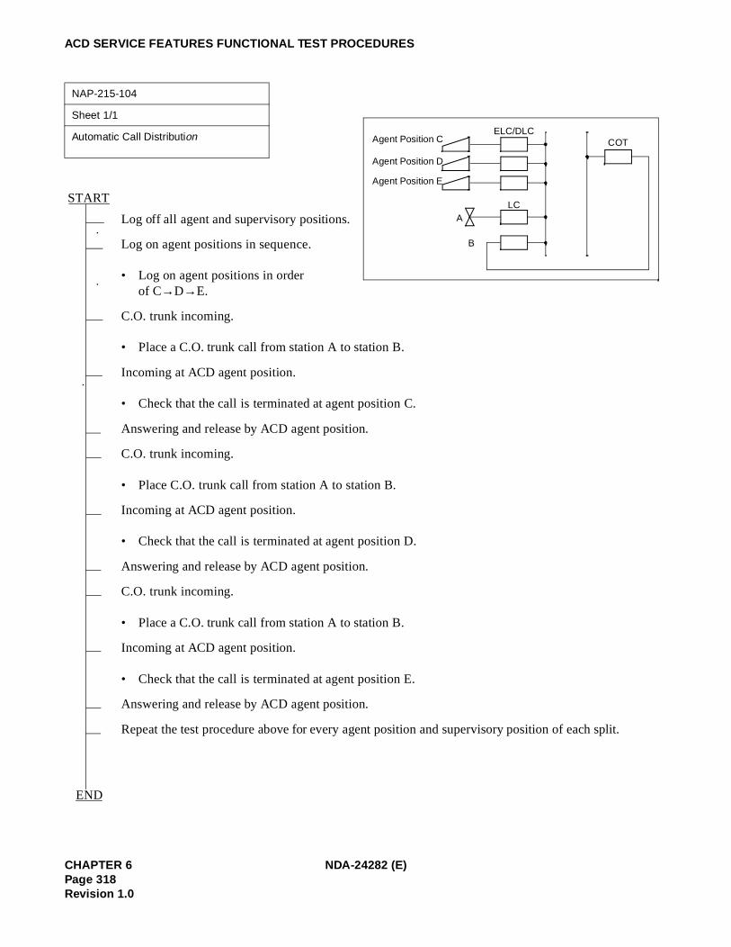
ACD SERVICE FEATURES FUNCTIONAL TEST PROCEDURES
NAP-215-104
Sheet 1/1
Automatic Call Distribution
Log off all agent and supervisory positions.
Log on agent positions in sequence.
• Log on agent positions in order of C→D→E.
C.O. trunk incoming.
• Place a C.O. trunk call from station A to station B.
Incoming at ACD agent position.
• Check that the call is terminated at agent position C.
Answering and release by ACD agent position.
C.O. trunk incoming.
• Place C.O. trunk call from station A to station B.
Incoming at ACD agent position.
• Check that the call is terminated at agent position D.
Answering and release by ACD agent position.
C.O. trunk incoming.
• Place a C.O. trunk call from station A to station B.
Incoming at ACD agent position.
• Check that the call is terminated at agent position E.
Answering and release by ACD agent position.
Repeat the test procedure above for every agent position and supervisory position of each split.
START
END
Agent Position CELC/DLC
LCA
B
COT
Agent Position D
Agent Position E
CHAPTER 6 NDA-24282 (E)Page 318Revision 1.0

ACD SERVICE FEATURES FUNCTIONAL TEST PROCEDURES
Note: This test does not use the Overflow service.Related commands: AADT, ACDCCV
NAP-215-105
Sheet 1/1
Delay Announcement
Log off all agent and supervisory positions.
C.O. trunk incoming.
• Place C.O. trunk calls sequentially from stations A, B and C to stations D, E and F respectively.
First delay announcement.
• Stations A, B and C shall hear the first delay announcement after the predetermined period of time.
Music on hold.
• Stations A, B and C shall hear the music on hold until the second delay announcement.
Second delay announcement.
Music on hold.
Release.
• Check that the incoming trunk is cleared automatically after the second delay announcement, then release stations A, B and C.
Apply the test procedure above for each trunk group.
START
END
Announcement Machine
COT
LCA
B
C
D
E
F
NDA-24282 (E) CHAPTER 6Page 319
Revision 1.0
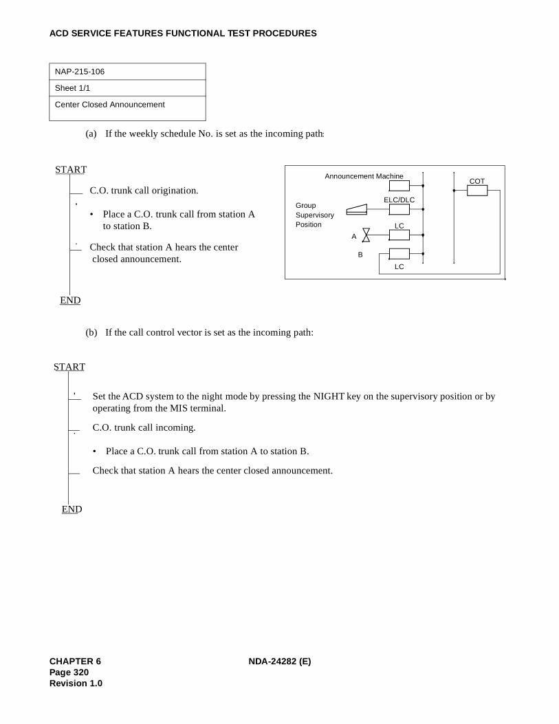
ACD SERVICE FEATURES FUNCTIONAL TEST PROCEDURES
(a) If the weekly schedule No. is set as the incoming path:
(b) If the call control vector is set as the incoming path:
NAP-215-106
Sheet 1/1
Center Closed Announcement
C.O. trunk call origination.
• Place a C.O. trunk call from station A to station B.
Check that station A hears the center closed announcement.
Set the ACD system to the night mode by pressing the NIGHT key on the supervisory position or by operating from the MIS terminal.
C.O. trunk call incoming.
• Place a C.O. trunk call from station A to station B.
Check that station A hears the center closed announcement.
Announcement Machine
ELC/DLC
A
B
COT
LC
LC
Group Supervisory Position
START
END
START
END
CHAPTER 6 NDA-24282 (E)Page 320Revision 1.0

ACD SERVICE FEATURES FUNCTIONAL TEST PROCEDURES
NAP-215-107
Sheet 1/1
Overflow
Log on the ACD agent and supervisory positions of the overflow originationsplit.
Log on the ACD agent and supervisory positions of the overflow destination split.
C.O. trunk incoming.• Place C.O. trunk calls sequentially
from stations A, B and C to stations D, E and F respectively.
(Overflow period elapsed).
Call termination at overflow destination split.
Answering by ACD agent position.• At the moment an agent position answers, it hears the ACD call transfer identification tone, after
which the communication can be started.
Release of ACD agent position.
Apply the test procedure above to each trunk group for which Overflow has been set.
START
END
F
D
E
COT
ELC/DLC
C
A
B
LC
G H I J
Overflow Designation Split
Overflow Origination Split
NDA-24282 (E) CHAPTER 6Page 321
Revision 1.0

ACD SERVICE FEATURES FUNCTIONAL TEST PROCEDURES
Note: After MON key is pressed, “BARGE?” is displayed. At that time, monitoring is abandoned by one of thefollowing operations.• Dial “1” + “#” (Three-party conference will be established.)• Press MON key again
NAP-215-108
Sheet 1/1
Emergency Recorder
C.O. trunk call incoming.• Place a C.O. trunk call from station
A to station B.
Incoming at ACD agent position.
Answering by ACD agent position.
Emergency recording operation.• Press the EMER key on the agent position.
Incoming at supervisory position.• When the ACD calls is terminated at the supervisory position, the LCD on the supervisory position
indicates the emergency recording request and the MON lamp also illuminates.• At the same time, the recorder starts recording.• In the period above, the agent position and C.O. trunk is in the communicating status.
Answering by supervisory position.• The supervisory position answers the call as an ACD call and monitors it (three-party conference call
does not occur).• The agent position can confirm the answering of the supervisory position by the change of the lamp
indication on the agent position (flashing steady) as well as from the LCD display.
Confirmation of recording.• Check that the call is recorded by the recorder.
The supervisory position presses the MON key to start three-party conference call. Note
Release by ACD agent position.• When the agent position releases the incoming C.O. trunk call, it is transferred to the supervisory
position.
Confirmation of communication.• Check that the supervisory position is communicating with the C.O. trunk.
Release by supervisory position.
Apply the test procedure above to all splits.
START
END
ELC/DLC
A
B
COT
LC
LC
ELC/DLC
RecorderAnnouncement Trunk
Supervisory position
Agent position
CHAPTER 6 NDA-24282 (E)Page 322Revision 1.0

ACD SERVICE FEATURES FUNCTIONAL TEST PROCEDURES
NAP-215-109
Sheet 1/1
After Call Work (Manual)
Log off all ACD agent and supervisory positions, then log on only one position.
C.O. trunk incoming.• Place C.O. trunk call from station A to station C.
Incoming at ACD agent position.
Answering by ACD agent position.
After Call Work activation.• Press the WORK key so that the WORK lamp illuminates.
C.O. trunk incoming.• Place a C.O. trunk call from station B to station D.
Release by ACD agent position.• The agent position can end communication with station A by pressing the RELEASE key.
Confirmation of After Call Work mode.• Check that, when the agent position release, the next call is not terminated at it.
Release of After Call Work mode.• Press the WORK key again so that the WORK lamp goes out.
Incoming at ACD agent position.
Answering by ACD agent position.• The agent position starts communication with station B.
Release by ACD agent position.
Apply the test procedure above to all splits.
START
END
COT
LCA
B
C
D
ELC/DLCAgent Position
NDA-24282 (E) CHAPTER 6Page 323
Revision 1.0

ACD SERVICE FEATURES FUNCTIONAL TEST PROCEDURES
NAP-215-110
Sheet 1/1
After Call Work (Automatic)
Log off all ACD agent and supervisory positions, then log on only one position.
Office data change.• Using the ACDSPL command, assign 0 (Automatic After Call Work mode setting) to parameter
AFTER.
C.O. trunk incoming.• Place a C.O. trunk call from station A to station C.
Incoming at ACD agent position.
Answering by ACD agent position.
C.O. trunk incoming.• Place a C.O. trunk call from station B to station C.
Release by ACD agent position, automatic setting of After Call Work mode.• Check that, when the agent position release, the After Call Work mode is set automatically.
Release of After Call Work mode.• Press the WORK key so that the WORK lamp goes out.
Incoming at ACD agent position.
Answering by ACD agent position.• The agent position starts communication with station B.
Release by ACD agent position.
Release of office data.
Apply the test procedure above to all splits.
START
END
COT
LCA
B
C
D
ELC/DLCAgent Position
CHAPTER 6 NDA-24282 (E)Page 324Revision 1.0

ACD SERVICE FEATURES FUNCTIONAL TEST PROCEDURES
NAP-215-111
Sheet 1/1
Assistance
C.O. trunk incoming.• Place a C.O. trunk call from station A to station B.
Incoming at ACD agent position.
Answering by ACD agent position.
Assistance activation.
Press the ASSIST key on the agent position so that the ASSIST lamp illuminates.
Incoming at supervisory position.• The call is terminated as non-ACD call to the supervisory position.
Answering by supervisory position.• The communication between the agent position and supervisory position starts, while the C.O. trunk
call is held.
Three-party conference call.• Press the CONF key on the agent position to start three-party conversation.
Release by ACD agent position.• The communication takes place between the C.O. trunk (station A) and supervisory position.
Release.
Apply the test procedure above to all splits.
START
END
ELC/DLC
A
B
COT
LC
ELC/DLC
Supervisory position
Agent position
NDA-24282 (E) CHAPTER 6Page 325
Revision 1.0

ACD SERVICE FEATURES FUNCTIONAL TEST PROCEDURES
NAP-215-112
Sheet 1/1
Auxiliary Work
Log off all ACD agent and supervisory positions.
Set one of the ACD agent positions to the Auxiliary Work mode. • Press the AUX WORK key so that the
AUX WORK lamp illuminates.
C.O. trunk incoming.• Place a C.O. trunk call from station A to station B.
Confirmation of Auxiliary Work mode.• Check that the incoming call is not distributed to the agent position.
Release of Auxiliary Work mode.• Press the AUX WORK key again so that the AUX WORK lamp goes out.
Incoming at ACD agent position.
Answering by ACD agent position.
Release by ACD agent position.
Apply the test procedure above to all splits.
START
END
Agent Position ELC/DLC
LC
A
B
COT
CHAPTER 6 NDA-24282 (E)Page 326Revision 1.0

ACD SERVICE FEATURES FUNCTIONAL TEST PROCEDURES
Note: If one of the following operation is performed at this time, monitoring is abandoned.• Dial “1” + “#” (A three-party conference will be established.)• Press MON key again
NAP-215-113
Sheet 1/1
Monitoring–ACD Supervisor
C.O. trunk incoming.• Place a C.O. trunk call from station A to station B.
Incoming at ACD agent position.
Answering by ACD agent position.
Monitoring Activation from Supervisory Position
(1) Press the MON key on the supervisory position.(2) Dial Agent ID code+# or 0+Agent position station No. for non-ACD calls+#.
Monitoring.• The supervisory position can monitor the conversation between station A and the agent position.• The supervisory position can monitor the call but cannot join the conversation.
Supervisory Override Operation
• Press the MON key on the supervisory position again. “BARGE?” is displayed. Note• The agent position and the call originator (station A) hear the warning tone.
Release.
Apply the test procedure above to all splits.
START
END
Supervisory Position
ELC/DLC
LCA
B
COTELC/DLC
Agent Position
NDA-24282 (E) CHAPTER 6Page 327
Revision 1.0

ACD SERVICE FEATURES FUNCTIONAL TEST PROCEDURES
NAP-215-114
Sheet 1/2
Night Service
Use one of the following three methods to change into the night mode.(1) Automatic changeover into the night mode
based on the ACD call control vector (Night Announcement setting using ACD CCV command).
(2) Pressing the NIGHT key on the supervisory position of split C; as this display confirmation message Night Mode?, enter 1# to change over into the night mode.
(3) Changeover into the night mode by means of operation at the MIS terminal of the supervisory posi-tion.
Night Announcement
• Place a C.O. trunk call from station A to station B in the special night split.
Station A hears the night announcement.
Apply the test procedure above to all splits.
Using the ACD CCV command, change the night services of the split and test each of the following ser-vices repeatedly.
Night Service Change
Using the ACD CCV command, change the night services of the split and test each of the following ser-vices.
Night Transfer to Station
• Place a C.O. trunk call from station A to station B.
Call incoming at transfer destination station.
A
START
ELC/DLC
LCA
B
COT
ATI
ELC/DLC
Announcement Trunk
Split C
D: ATT
CHAPTER 6 NDA-24282 (E)Page 328Revision 1.0

ACD SERVICE FEATURES FUNCTIONAL TEST PROCEDURES
NAP-215-114
Sheet 2/2
Night Service
Answering by station.
Release by station.
Apply the test procedure above to all splits.
Night Transfer to Attendant
• Place a C.O. trunk call from station A to station B.
Call incoming at transfer destination attendant console.
Answering by ATTCON.
Release by ATTCON.
Apply the test procedure above to all splits.
Night Transfer to Outside
• Place a C.O. trunk call from station A to station B.
Call incoming at transfer destination C.O. trunk.
Answering by C.O. trunk.
Release by C.O. trunk.
Apply the test procedure above to all splits.
END
A
NDA-24282 (E) CHAPTER 6Page 329
Revision 1.0

ACD SERVICE FEATURES FUNCTIONAL TEST PROCEDURES
NAP-215-115
Sheet 1/1
Abandoned Call Search
Abandoned Call Search
C.O. trunk call origination.• Place a call from station A to station B and a C.O. trunk call is terminated to agent positions.• At this time, agent positions shall be in the manual answer mode.
After checking that the CW lamp on the agent position illuminates, station A releases the call.• Check that the CW lamp on the agent position goes out and that the call is released.
START
END
LCA
B
COT
ELC/DLC
Agent Position
CHAPTER 6 NDA-24282 (E)Page 330Revision 1.0

ACD SERVICE FEATURES FUNCTIONAL TEST PROCEDURES
NAP-215-116
Sheet 1/1
Trunk Trouble Report
C.O. trunk call incoming.• Place a C.O. trunk call from station A to station B and a C.O. trunk call is terminated to agent posi-
tions.
The call is terminated to agent positions. An agent position answers the call.
While the agent position is busy, press the TRK/TRBL key on station B.
The connection information is output at the MIS terminal.
A system message is output.
Apply the test procedure above to all agent and supervisory positions of all splits.
START
END
LCA
B
COT
ELC/DLC
Agent Position
NDA-24282 (E) CHAPTER 6Page 331
Revision 1.0

This page is for your notes.
CHAPTER 6 NDA-24282 (E)Page 332Revision 1.0

CHAPTER 7 PBX AND ACD COMMAND PROGRAMMING
1. GENERAL
This chapter explains the commands which are used exclusively for the NEAX2400 CallCenterWorX-Enter-prise ACD system. For other related commands, refer to the NEAX2400 IMX Office Data Specification. Whenengaging in command operations concerning the ACD system, ensure to use both this manual and NEAX2400IMX Office Data Specification.
2. COMMANDS
2.1 NEAX2400 IMX COMMANDS
For ACD commands, see Section 2.2, “ACD Commands” in this chapter.
Note: Assign “1” to parameter “OAI” of “MMNF” command prior to using OAI command.
Table 7-1 NEAX2400 IMX Command List in Alphabetical Order
COMMAND NAME
FULL NAME
AADT Assignment of Announcement/Dictation Trunks
AADTN Assignment of Announcement/Dictation Trunks for NDM
ACNO Assignment of Conversion Number Data
ACNOL Assignment of Conversion Number Data for LDM
ACNON Assignment of Conversion Number Data for NDM
AKYD Assignment of Key Data for Dterm
ALGNN Assignment of Telephone Number Data for NDM
ALGSN Assignment of Telephone Station Data for NDM
AMNO Assignment of Monitored Number
AMNOL Assignment of Monitored Number for LDM
AMNON Assignment of Monitored Number for NDM
AOKC Assignment of OAI Key Code
ASDT Assignment of Station Data
ASFC Assignment of Service Feature Restriction Class Data
ASYD Assignment of System Data
ASYDL Assignment of System Data into Local DM (LDM)
ASYDN Assignment of System Data in NDM
NDA-24282 CHAPTER 7Page 333
Revision 1.0

ASYD: ASSIGNMENT OF SYSTEM DATA
ASYD: Assignment of System Data
1. Function
This command is used to assign and change system data in the NEAX2400 IMX.
2. Precautions
1. ASYD is divided into three sections, as follows:
a. Assignment of System Data-1.(SYS 1) - System-wide control parameters.
b. Assignment of System Data-2.(SYS 2) - Service feature availability, on a tenant basis.
c. Assignment of System Data-3.(SYS 3) - System-wide ringing patterns and hookswitch timing.
2. Only ASYD System Data-1 parameters relate to the functioning of ACD system.
3. System data must be entered using hexadecimal numbers. Refer to the ACD system Job Specificationfor the applicable system data.
3. Parameters
SYS: System Data Items1: System Data 12: System Data 23: System Data 3
TN: Tenant NumberINDEX: System Data Index
SYS INDEX1 0-5112 0-153 0-31
DATA: System Data (Hexadecimal)
CHAPTER 7 NDA-24282Page 334Revision 1.0

ASYD: ASSIGNMENT OF SYSTEM DATA
System Data-1 Programming Sheet
Note: This Data Programming Sheet is only for the data to be set in the ACD System. Be sure to use this DataProgramming Sheet together with the Data Programming Sheet for “ASYD” command described in theNEAX2400 IMX Office Data Specification.
Note 1: For ACD system to be activated through Fusion network, this data is programmed in the node providingACDP only. Other system data than INDEX2 must be set to all nodes to be provided ACD trunk-Fusionwithin Fusion network.
Note 2: When changing this index from 02 (normal setting for non- OAI/ACD system) to 04, you must back up DMto the HDD of the system.
Note 3: Valid since the PBX software Series 7300 and the ACD software R1.
SYSTEMDATATYPE(SYS)
SYSTEMDATA
INDEX(INDEX)0 ~ 511
DATA(DATA)00 ~ FF(Hex)
BITCORRESPONDING
DATASYSTEM DATA CONTENTS
DATA0/1
BIT
1
2 01 1 b01=ACDP is used(Assign 01 Hex) Note 1
27 0 b4ACD in Service (Fixed Data) 0 = In service; 1 = Out of service
31 04 1 b2 Note 2
42 b2System Message “5-Q” is output.0/1 = No/Yes Note 3
47
b0Traffic Measurement Indication0/1 = CCS Indication/Erlang Indication
1 b1 b2 b1
TCFI timer: 0 0 = 2 sec. intervalNote 4 1 1 = Application Dependent
(Standard)0 1 = 4 sec. interval1 0 = 8 sec. interval
1 b2
0 b30 = Display last number for TCFD1 = Display message Note 5
b4ACD Busy Tone Control0/1 = No/Yes Note 6
b7Traffic Measurement for Terminal and Route Traffic0/1 = Out/In Service
NDA-24282 CHAPTER 7Page 335
Revision 1.0

ASYD: ASSIGNMENT OF SYSTEM DATA
Note 4: Terminal Control Facility Indirect is used for displays, LED functions, and chimes for ACD positions. Thestandard choice has both bit 1 and bit 2 set to “1”.
Note 5: Terminal Control Facility Direct is used for certain ACDP entries and displays from ACD positions.
Note 6: ASYD, System Data 1, index 59, bit 2 must also be set to a 1 for this feature to operate.
Note 1: Must be set to “1” for an “IF NOT QUEUED GO TO BUSY 11 step to return busy tone to a self-directingtrunk (CCV function on DIDs etc.). This does not work with ringdown type trunks.
Note 2: When the announcement service is used in Fusion network, this data is set to nodes that accommodates theannouncement trunk.
Note 3: Be sure to assign the data value “1” here (see Chapter 1, Section 1.3, “Precaution on Using the ACD Fea-tures”).
Note 4: When changing the value of this data bit to “0” (OAI/ACD Service Provided) from “1” (OAI/ACD ServiceNot Provided), system initialization must be executed.
System Data-1 Programming Sheet
SYSTEMDATATYPE(SYS)
SYSTEMDATA
INDEX(INDEX)0 ~ 255
DATA(DATA)00 ~ FF(Hex)
BITCORRESPONDING
DATA SYSTEM DATA CONTENTS
DATA0/1
BIT
1
59 b2DID busy condition0/1 = No/Yes Note 1
70 1 b6ACD Announcement service 0/1=Out of service/In service. Note 2
79
b4Warning tone sent to the monitored position.0/1=No/Yes Note 3
0 b6OAI/ACD Service Note 40 = ACD In Service; 1 = ACD Out of Service
80 0 b3
Line of the LCD for static ACD messages (Break, Ready, etc.) display.0/1=top line/second line
CHAPTER 7 NDA-24282Page 336Revision 1.0

ASYD: ASSIGNMENT OF SYSTEM DATA
Note 1: This bit is always set to “1”.
Note 2: This bit is set to “1” for dual ACDP’s. If single ACDP, this bit is set to “0”. This bit is always set to “0”for internal ACDP.
Note 3: The announcement service for fusion network, “1 = DAT control” is not available.
System Data-1 Programming Sheet
SYSTEMDATATYPE(SYS)
SYSTEMDATAINDEX
(INDEX)0 ~ 511
DATA(DATA)00 ~ FF(Hex)
BITCORRE-
SPONDINGDATA SYSTEM DATA CONTENTS
DATA0/1
BIT
1
89 b3CPU ACT/ST-BY Change Function0=Out of Service; 1=In Service
207
b0ACDP (No. 0 System) Mounting Status Indication0/1 = Not Mounted/Mounted Note 1
b1ACDP (No. 1 System) Mounting Status Indication0/1 = Not Mounted/Mounted Note 2
241
1 b2Call Event Processing0/1 = Invalid/Valid (Always assign 1)
1 b3Details of SCF Error Notification0/1 = Ineffective/Effective
448 1 b1 Higher ACDP controlling capability
449
b0SCF Call origination from the first party notification0/1 = Ineffective/Effective
b2
Access to Announcement trunk is controlled:0 = by the timer1 = by the DAT Note 3
NDA-24282 CHAPTER 7Page 337
Revision 1.0

ASYDL: ASSIGNMENT OF SYSTEM DATA INTO LOCAL DM (LDM)
ASYDL: Assignment of System Data into Local DM (LDM)
1. Function
This command is used to assign and change system data for the ACD activated via FCCS.
2. Precautions
ASYDL command is comprised with System Data-1, INDEX 512-1535.
3. Parameters
Refer to the programming sheet in the following pages.
CHAPTER 7 NDA-24282Page 338Revision 1.0

ASYDL: ASSIGNMENT OF SYSTEM DATA INTO LOCAL DM (LDM)
System Data (LDM) -1 Programming Sheet
SYSTEMDATATYPE (SYS)
SYSTEMDATAINDEX
(INDEX)512-1535
DATA (DATA) 00 – FF (Hex)
BITCORRESPONDING
DATA SYSTEM DATA CONTENTS
DATA0/1
BIT
1
513LDM (Local Data Memory) usage. Assign data “1” (the memory block is used) for the corresponding memory block. Normally Assign “01”.
515IP Address (Hex) for PBX over External LANNote: This data is valid when the PBX is connected to the
external PC LAN.When default IP address (172.16.253.0) for the PBX is used, this data setting is not necessary.Example: IP Address: 133.206.8.1
516
517
518
519Subnet Mask (Hex) for PBX over External LANNote: This data is valid when the PBX is connected to the
external PC LAN.When default IP address (172.16.253.0) for the PBX is used, this data setting is not necessary.Example: Subnet Mask: 255.255.0.0
520
521
522
523Default Gateway Address of External LANGateway Address (IP address of Router) of Network con-necting PBX.Note: This data is valid when the PBX is connected to the
external PC LAN.If no Network Gateway, assignment data is 00 Hex.in Index 523 through 526.
Example: Default Gateway Address: 133.206.8.254
524
525
526
INDEX Set Hex515 85
516 CE
517 08
518 01
INDEX Set Hex519 FF
520 FF
521 00
522 00
INDEX Set Hex523 85
524 CE
525 08
526 FE
NDA-24282 CHAPTER 7Page 339
Revision 1.0

ASYDL: ASSIGNMENT OF SYSTEM DATA INTO LOCAL DM (LDM)
Note 1: For ACD system to be activated through Fusion network, this data is programmed in the node providingACDP only. Other data must be set to all nodes within Fusion network.
Note 2: Available since the PBX software Series 7400 and the ACD software R3.
Note 3: This data is used in the network providing multiple ACDPs.
Note 4: The identical data value must be assigned to all nodes.
Note 5: This data is necessary at all nodes. Assign the self FPC at the terminating node.
Note 6: For ACD service provided within Fusion network, the data value (FPC) in these indexes must be pro-grammed the same.
1 533 FPC of the node providing ACDP
1
864
1 b0 0/1 = Built-in IP, ACDP is not used/used Note 1
b1
Output the system message (4-R) when TCP-IP connection is normally disconnected.0/1 = Effective/Ineffective
b20/1 = “AGENT ANYWHERE” is out of service/in serviceNote 2, Note 3
b3 0/1 = “Multiple ACDPs” is not available/available Note 2
b4 Assign number of ports of Status Monitoring for terminal (SMFN). Note 2, Note 4b4 = 0, b5 = 0 (2 ports)b4 = 1, b5 = 0 (8 ports)
b5
865
FPC of the node providing IP.(Assign 0 when the ACD service is activated in the self node only.)FPC: 1-253 (01 Hex – FD Hex)Note 5, Note 6
866
FPC of the node providing ACDP(Assign 0 when the ACD service is activated in the self node only.)FPC: 1-253 (01 Hex – FD Hex)Note 5, Note 6
System Data (LDM) -1 Programming Sheet
SYSTEMDATATYPE (SYS)
SYSTEMDATAINDEX
(INDEX)512-1535
DATA (DATA) 00 – FF (Hex)
BITCORRESPONDING
DATA SYSTEM DATA CONTENTS
DATA0/1
BIT
CHAPTER 7 NDA-24282Page 340Revision 1.0

ASYDN: ASSIGNMENT OF SYSTEM DATA IN NDM
ASYDN: Assignment of System Data in NDM
1. Function
This command is used to specify the system data for the Fusion Network.
2. Precautions
1. The data assigned by this command determines the service condition which affects the other nodes inthe Fusion Network.
2. Data for ASYDN assigned at Network Control Node (NCN) has priority over data for ASYDL assignedat LN (Local Node) in the Fusion Network.
3. The ASYDN command consists of SYS1, INDEX 0 - 1535.
4. For more details, see the “Fusion System Manual”.
System Data (NDM) Programming Sheet
SYSTEMDATATYPE (SYS)
SYSTEMDATAINDEX
(INDEX)0-1535
DATA (DATA) 00 – FF (Hex)
BIT CORRESPONDING
DATA SYSTEM DATA CONTENTS
DATA0/1
BIT
1514
Network Data Memory (NDM) usage. Assign data “1 (the memory block is used)” for the corresponding memory block.
533 FPC number of the node that has the standard VNDM (1-253).
bit Memory Block
b0 Memory Block 0
b1 Memory Block 1
b2 Memory Block 2
b3 Memory Block 3
b4 Memory Block 4
NDA-24282 CHAPTER 7Page 341
Revision 1.0

AOKC: ASSIGNMENT OF OAI KEY CODE
AOKC: Assignment of OAI Key Code
1. Function
This command is applied to define the usage of Dterm buttons (line/feature key and flex key).
2. Precautions
1. AOKC must be programmed before AKYD is programmed.
2. For station assignment, the OAI Key Codes correspond to the Function Key Code (FKY) range from 34through 47 (refer to AKYD).
3. After the OAI key code data is changed or deleted by this command or the system initial is executed,newly programmed data is invalid for the first operation.
4. OAI key code data programmed in this command must be set to all nodes to be provided ACD servicefor Fusion network.
3. Parameters
KEY-CODE: OAI Key Code (1-31)
F-KIND: Kind of Facility1= (MSF) Terminal Mode Set Facility2= (TMF) Terminal Multiple Information Transfer Facility3= (OAC) OAI Access Code Request4= (KTF) Key Code Transfer Facility5~15= Not used
C-TONE: Confirmation Tone0 = Confirmation Tone1 = No Tone
NND: Number of Necessary Digits (available for F-KIND=3 only)
OP-CODE: Operation Code128 thru 191 (for F-KIND = 1)192 thru 255 (for F-KIND = 2)
Note 1: The following operation codes are not available for OAI system when OAI system and ACD system are usedin the same Fusion network.
When F-KIND=1 (MSF) OP-CODE 185~191When F-KIND=2 (TMF) OP-CODE 248~255
CHAPTER 7 NDA-24282Page 342Revision 1.0

AOKC: ASSIGNMENT OF OAI KEY CODE
Note 1: For the quick reference table of KEY CODE and KYN, refer to AKYD command.
Note 2: Confirmation Tone (C-TONE)0/1 = Confirmation Tone/No Tone
OAI Key Code Data Programming Sheet
OAI KEY CODE (KEY
CODE)1 ~ 31Note 1
KIND OF FACILITY(F-KIND)
1 ~ 15
CONFIRMATION TONE
(C-TONE)0/1
Note 2
OPERATION CODE
(OP-CODE)128 ~ 255
FUNCTION KEY(FKY)
1 1 1 187 Break
2 2 1 252 Auto/Manual (AUTO/MAN)
3 Not used
4 2 1 253 Work
5 1 1 188 Night (NIGHT)
6 2 1 250Trunk Trouble Report (TRK TRBL)
7 1 1 189 Tally (TALLY)
8 2 1 254 Assistance (ASSIST)
9 2 1 255 Emergency Recorder (EMER)
10 1 1 190 Log on/off (LOG ON/OFF)
11 Not used
12 1 1 191 Monitor/Barge (MON/BARGE)
13 Not used
14 2 1 249 CW lamp
15 ~ 31 Not used
NDA-24282 CHAPTER 7Page 343
Revision 1.0

ASDT: ASSIGNMENT OF STATION DATA
ASDT: Assignment of Station Data
1. Function
This command is used to assign, delete and display station data. If the station number designated has al-ready been assigned, the current data is displayed. If new data is to be assigned, the old data must be deletedbefore the new data can be entered.
2. Precautions
1. The Route Restriction Class data (RSC) works in conjunction with the Assignment of Route RestrictionData command (ARSC).
2. The Service Feature Restriction Class data (SFC) works in conjunction with the Assignment of ServiceFeature Restriction Class command (ASFC).
3. When the station to be deleted is busy, an error indication is provided.
4. If station data is deleted, the data of the stations assigned by the AKYD command is also deleted.
3. Parameters
TN: Tenant NumberSTN: Station NumberLENS: Line Equipment Number (6 digits)TEC: Telephone Equipment Class (1 ~ 31)
3= DP/PB (for Hot position) / (Analog position)12= Dterm (for My-Line)18= Virtual Line Appearance (for ACD Line)
RSC: Route Restriction Class (0 ~ 15)For assignment of RSC from ARSC command.
SFC: Service Feature Class (0 ~ 15)For assignment of SFC from ASFC command.
Note: For the ACD lines (Virtual Lines), the SFC must be separate from all other SFCs in the system.This does not apply to Hot Positions or Analog Positions.
Note: Stations must be programmed in the Network Node. Use ALGSN command.
CHAPTER 7 NDA-24282Page 344Revision 1.0

ASDT: ASSIGNMENT OF STATION DATA
System Data Programming Sheet
TENANT
NUMBER (TN) 1 ~ 10
SYSTEM 1IMG
IMX-U
MG 00, 01 00 ~ 07
STATION NUMBER (STN)
MAXIMUM 5 DIGITS
LINE EQUIPMENT NUMBER (LENS)
MG U
0 ~ 3
G
00 ~ 23
LV
0 ~ 7
TELEPHONEEQUIPT.
CLASS (TEC) 1 ~ 31
ROUTE RESTRICTION CLASS (RSC)
0 ~ 15
SERVICE FEATURE
CLASS (SFC) 0 ~ 15
MAKE BUSYINFORMA-
TION(MB) 0/1
4IMG00 ~ 07
NDA-24282 CHAPTER 7Page 345
Revision 1.0

ASFC: ASSIGNMENT OF SERVICE FEATURE RESTRICTION CLASS DATA
ASFC: Assignment of Service Feature Restriction Class Data
1. Function
This command is used to assign and display Service Feature Restriction information according to theService Feature Restriction Class (SFC) of the Station.
2. Precautions
1. For the SFC of ACD line of an agent position, be sure to assign RES = 1 (A Direct call is restricted) forSFI = 95 (Direct Call Restriction). Assign RES = 0 (A Direct call is allowed) for SFC of non-ACD-lines
2. For details of SFIs other than SFI = 95, refer to “ASFC” command table in NEAX2400 IMX Office DataSpecification
3. Service Feature Restriction Class data programmed in this command must be set to all nodes to beprovided ACD trunk for Fusion network.
3. Parameters
DAY/NIGHT: Day/Night ModeD= Day ModeN= Night Mode
TN: Tenant NumberSFC: Service Restriction Class (0 ~ 15)SFI: Service Feature Index (1 ~ 255) (Enter 95.)
95= 1 Direct Call Restriction (for ACD)118= Live Record (for AD-16/40 vm)
RES: Restriction Data0= Restricted1= Allowed
Note: When WRT? = Y is entered the value of the SFC automatically increases by one.
CHAPTER 7 NDA-24282Page 346Revision 1.0

ASFC: ASSIGNMENT OF SERVICE FEATURE RESTRICTION CLASS DATA
Note 1: Restriction Data (RES) is assigned in the squares where SFI and SFC cross. When unassigned, RestrictionData is set as “0” (Restricted status). Allowed Status data is “1”, and must be assigned to allow the feature.
Note 2: Service Feature Index (SFI) 95.
• For SFC of ACD line of Agent Position and Supervisory Position, assign RES = 1 (Allowed).For SFC of Non-ACD line of Agent Position and Supervisory Position, assign RES = 0 (Restricted).For SFC of Stations other than the Agent Position and Supervisory Position, assign RES = 0 (Restrict-ed).
Note 3: SFI118 may be set to a 1 (for Live Record), when using an AD-16/40 vm system.
Service Feature Restriction Class Data Programming Sheet
DAY/NIGHTMODE
(DAY/NIGHT)D/N
TENANTNUMBER
(TN)
SERVICERESTRICTION
CLASS(SFC)0 ~ 15
SERVICE FEATURE INDEX (SFI)
1 ~ 255
1 ~ 94 95 96 ~ 117 118 119 ~ 255
0
1
2
3
4
5
6
7
8
9
10
11
12
13
14
15
Note 2
NDA-24282 CHAPTER 7Page 347
Revision 1.0

AKYD: ASSIGNMENT OF KEY DATA FOR DTERM
AKYD: Assignment of Key Data for Dterm
1. Function
This command is used to assign, delete, and display the following key data corresponding to each line/feature buttons of Dterm. For details of this command, refer to “AKYD” command in NEAX2400 IMXOffice Data Specification.
• Line Key Data
• Function Key Data
2. Precautions
1. Before assigning the key data for Dterm by this command, be sure to assign the station data (TN, STN,TEC = 12 (Dterm)) of the Dterm by ASDT command. The station number assigned by ASDT commandis referred to as “My Line”.
Note: The “My Line” corresponds to the physical port associated with the LENS of a DLC/ELC card.
2. By assigning another station line to a function button by this command, an incoming call terminated toa station line other than My Line can be answered or can be transferred to elsewhere as in the case ofthe My Line. A station line other than My Line is referred to as a “Sub Line”. A “Sub Line” can beassigned not only to a Dterm but to any conventional telephone. In addition, the station data for My Lineand Sub Line must be assigned via the ASDT command before the key data is assigned. When the SubLine and the My Line belong to different tenants, use the ATNR command and clear the “Tenant toTenant Restriction”.
3. A Multi-Line key (the key for My Line and Sub Line) on the Dterm can be assigned as “Prime Line”. Ifthe Prime Line is not assigned, the My Line will serves as the Prime Line. When the user goes off-hook,the Prime Line is automatically connected to the Dterm.
4. A virtual line can be assigned as a Sub Line of the Dterm. The virtual line can be used the same way asthe My Line for outgoing calls and other service operations.
Note: Virtual Line — A virtual LENS exists only in memory, but does not exist physically. Data can be assignedbut no hardware is provided for it; ex. LENS = 000311. The virtual LENS is assigned station data using theASDT command in the same way as for on ordinary line. (The telephone class is TEC = 18: Virtual Line)
5. When this command is used, the DLC/ELC card must be reinitialized (MB switch UP-DOWN).
6. Key data programmed in this command must be set to all nodes to be provided ACD service for Fusionnetwork.
Note: Use Command ADKS for Series E Dterm.
CHAPTER 7 NDA-24282Page 348Revision 1.0

AKYD: ASSIGNMENT OF KEY DATA FOR DTERM
3. Parameters
TN: Tenant Number (for My Line)STN: Station Number (for My Line)KYI or KYI2: 1= Function Key
2= Multi-lineKYN or KYN2: Key numberTP: Type of Dterm (Enter 2 or 3)
2= ACD Position (8/16 button + 8 Flex)3= ACD Position (24 button + 8 Flex or 16-button with Add on Module + 8 Flex for
Dterm Series III/32 button type with Add on Module + 8 Flex for Dterm Series E)PRI: Priority of Answering a Call (0 ~ 4)
Must be programmed as 0.LN PRE: Line Preference (0/1):
Must be programmed as 0.PLTN: Tenant Number of the Prime Line.PLSTN: Station Number of the Prime Line.S: Off-hook suppression to Prime Line. Note 2
0= Off-hook suppression disabled.1= Off-hook suppression enabled.
Note: “WRT?” prompt is displayed after the function button data have all been assigned.
Note 1: The ACD Line Number must be programmed here (Virtual Line).
Note 2: Must be enabled to Prime Line (ACD Line).
Note 1
NDA-24282 CHAPTER 7Page 349
Revision 1.0

AKYD: ASSIGNMENT OF KEY DATA FOR DTERM
FKY: Function Key (valid for KYI=1)34= OAI Key 1 (Break)35= OAI Key 2 (Auto/Man) Note 337= OAI Key 4 (Work)38= OAI Key 5 (Night)39= OAI Key 6 (Trk Trbl (Trunk Trouble))40= OAI Key 7 (Tally)41= OAI Key 8 (Assist (Assistance Key))42= OAI Key 9 (Emer (Emergency Key))43= OAI Key 10 (Log On/Off)44= OAI Key 11 (Answer)45= OAI Key 12 (Mon/Barge (Monitor/Barge))47= OAI Key 14 (Call Waiting Lamp)52= Speaker59= Release
KD: Kind of Line (Valid for KYI=2)0= Line
TN: Tenant Number (for Sub-Line )STN: Station Number (for Sub-Line)RG: Ringing Information for Each Line (0 ~ 7)
Note 3: Automatic/Manual answer key, toggles between Automatic Answer Mode and Manual Answer Mode.
Note 4: The ACD Line Number must be programmed here (Virtual Line).
RG RINGING DURING DAY MODE RINGING DURING NIGHT MODE DELAY TIME
01234567
No RingingRingingNo RingingNot usedRingingRingingRingingRinging
No RingingNo RingingRingingNot usedRingingRingingRingingRinging
0 sec.0 sec.
30 sec.20 sec.10 sec.0 sec
Note 4
CHAPTER 7 NDA-24282Page 350Revision 1.0

AKYD: ASSIGNMENT OF KEY DATA FOR DTERM
Dterm Series E Flexible Key Assignments
• Standard
• ACD
KYN FKY FUNCTION
1 13 CONFERENCE
2 8 REDIAL
3 28 ANSWER
4 16 FEATURE
5 18 TRANSFER
6 57 RECALL
7 20 HOLD
8 52 SPEAKER
FEATURE
4
RECALL
6
CONF
1
REDIAL
2
SPEAKER
8ANSWER
3TRANSFER
5HOLD
7
KYN FKY FUNCTION
1 13 CONFERENCE
2 40 TALLY
3 34 BREAK
4 43 LOGON
5 18 TRANSFER
6 59 RELEASE
7 20 HOLD
8 37 WORK
LOG
4
RIS
6
CONF
1
TALLY
2
WORK
8BRK
3TRF
5HOLD
7
NDA-24282 CHAPTER 7Page 351
Revision 1.0

AKYD: ASSIGNMENT OF KEY DATA FOR DTERM
Dterm Key Data Programming Sheet (1/2)
MY LINE
TENANTNUMBER
(TN)
STATION NUMBER(STN)
PRIORITYOF
ANSWERINGCALL(PRI)0-4
PRIME LINE ALLOW OG
FROMPRIMELINE(S)0/1
MESSAGEWAITING
DATADISPLAY
SELECTION(MWD)
0/1
LINEPREFERENCE
(LN PRE)0/1
LINEPREFERENCEFOR SPEAKER
BUTTON(SPK)
0-3
LINEPREFERENCEFOR ANSWER
BUTTON(ANS)
0-2
LINEPREFER-
ENCEFOR OUTGO-
INGBUTTON
(ORG)0/1
TYPE OFDTERM
(TP)0-3
TENANTNUMBER(PL TN)
STATIONNUMBER(PL STN)
KEYNUM-BER
(KYN)
SERVICECONDITION
(KYI) 0 – 2
FEATUREKEY CODE
(FKY)1-320
KIND OFLINE(KD)0-2
MULTI LINE INTERCOM
TENANTNUMBER
(TN)
STATIONNUMBER
(STN)
RINGINFORMATION
FOREACH LINE
(RG)0-7
KIND OFINCOM(ICM)0-2
GROUP ID
NUM-BER
(G-ID)1-50
1
2
3
4
5
6
7
8
9
10
11
12
13
14
15
16
17
18
19
20
21
22
23
24
25
26
CHAPTER 7 NDA-24282Page 352Revision 1.0

AKYD: ASSIGNMENT OF KEY DATA FOR DTERM
Dterm Key Data Programming Sheet (2/2)
Note 1: When KYI=0 (None), it is not necessary to assign any data.When KYI=1 (FUNCTION), assign data for FKY only.When KYI=2 (Multi-Line), assign data for multiple telephone only.
KEYNUM-BER
(KYN)
SERVICECONDITION
(KYI) 0 – 2
FEATUREKEY CODE
(FKY)1-320
KIND OFLINE(KD)0-2
MULTI LINE INTERCOM
TENANTNUMBER
(TN)
STATIONNUMBER
(STN)
RINGINFORMATION
FOREACH LINE
(RG)0-7
KIND OFINCOM(ICM)0-2
GROUP ID
NUM-BER
(G-ID)1-50
27
28
29
30
31
32
33
34
35
36
37
38
39
40
F1
F2
F3
F4
F5
F6
F7
F8
NDA-24282 CHAPTER 7Page 353
Revision 1.0

AMNO: Assignment of Monitored Number
AMNO: Assignment of Monitored Number
1. Function
AMNO is used to assign monitored numbers into the PBX database. The numbers programmed in AMNOwill also be programmed into ACDPLT (the ACD database). The monitored numbers programmed inAMNO are the entry points for pilot numbers into the ACD system.
2. Precautions
1. When the monitored number (MNO) is deleted, delete MNO in ACDPLT prior to this command.
2. When UCD=1 is programmed in this command, UCD service should be programmed beforehand.
3. Parameters
TN: Tenant Number of Monitored NumberMNO: Monitored Number (maximum 5 digits. the number is the same as the pilot number
assigned in ACDPLT and must match the numbering plan of the NEAX2400 IMX.NMI: Number Monitored Index (1 ~ 4095)UCD: UCD degrade
0 – No1 – Yes
STN: UCD Control Station Number (Available for UCD=1) Note 1A/G: Station type of Hotel System Note 2
A: Administration StationG: Guest Station
MFC: G-2 Signal Data for MFC (0-3) Note 30 = ASFC, SFI 59 = 0 and SFI 60 = 01 = ASFC, SFI 59 = 1 and SFI 60 = 02 = ASFC, SFI 59 = 0 and SFI 60 = 13 = ASFC, SFI 59 = 1 and SFI 60 = 1
Note: Each monitored number must be assigned to different Monitored Number Index.“0”cannot be assigned at the first digit of the monitored number.
Note 1: When a C.O. trunk is used for UCD control station, UCD controlling station number should beprogrammed in ACSI in advance.
Note 2: For Business System, “A (Administration Station)” is assigned here.
Note 3: Valid for countries except Australia and North America.
CHAPTER 7 NDA-24282 (E)Page 354Revision 1.0

AMNO: Assignment of Monitored Number
Monitored Number Data Programming Sheet
TENANTNUMBER
(TN)1 ~ 10
MONITOREDNUMBER
(MNO)
NUMBER MONITOREDINDEX (NMI)
1 ~ 4095
UCD DEGRADE (UCD)
0/1
UCD CONTROLSTATION NUMBER
(STN)
ADMIN./GUEST(A/G)A/G
NDA-24282 (E) CHAPTER 7Page 355
Revision 1.0

AMNOL: Assignment of Monitored Number for LDM
AMNOL: Assignment of Monitored Number for LDM
1. Function
AMNOL is used to assign monitored numbers into the PBX database. The numbers programmed inAMNOL will also be programmed into ACDPLT (the ACD database). The monitored numbersprogrammed in AMNOL are the entry points for pilot numbers into the ACD service to be activated overFCCS. The monitored number programmed in AMNOL is available for only the self node.
2. Precautions
1. Prior to this command, Telephone number of the monitored number should be programmed in ALGNL.
2. When the monitored number (L_MNO) is deleted, delete L_MNO in ACDPLT prior to this command.
3. Parameters
UGN: User Group Number of Monitored Number (Fixed “1”)L_MNO: Telephone number of Monitored Number (maximum 5 digits. the number is the same
as the pilot number assigned in ACDPLT and must match the numbering plan of theNEAX2400 IMX).
L_NMI: Number Monitored Index (1 ~ 4095)UCD: UCD degrade
0 – No1 – Yes
TELN: UCD Control Station’s Telephone Number (Available for UCD=1) Note 1A/G: Station type of Hotel System Note 2
A: Administration StationG: Guest Station
MFC: G-2-Signal Data for MFC (0-3) Note 30 = ASFC, SFI 59 = 0 and SFI 60 = 01 = ASFC, SFI 59 = 1 and SFI 60 = 02 = ASFC, SFI 59 = 0 and SFI 60 = 13 = ASFC, SFI 59 = 1 and SFI 60 = 1
Note: Each monitored number must be assigned to different Monitored Number Index.“0”can not be assigned at the first digit of the monitored number.
Note 1: When a C.O. trunk is used for UCD control station, UCD controlling station number should beprogrammed in ACSIL in advance.
Note 2: For Business System, “A (Administration Station)” is assigned here.
Note 3: Valid for countries except Australia, U.S.A and Canada.
CHAPTER 7 NDA-24282 (E)Page 356Revision 1.0

AMNOL: Assignment of Monitored Number for LDM
Monitored Number Data (LDM) Programming Sheet
USERGROUP
NUMBER(UGN)
LOCALMONITORED
NUMBER(L_MNO)
MAX. 5 DIGITS
LOCAL NUMBERMONITORED
INDEX (L_NMI)1 ~ 4095
UCD DEGRADE(UCD)
0/1
UCD CONTROLTELN NUMBER
(TELN)MAX. 5 DIGITS
ADMIN./GUEST(A/G)A/G
NDA-24282 (E) CHAPTER 7Page 357
Revision 1.0

AMNON: Assignment of Monitored Number for NDM
AMNON: Assignment of Monitored Number for NDM
1. Function
AMNON is used to assign monitored numbers into the PBX database. The numbers programmed inAMNON will also be programmed into ACDPLT (the ACD database). The monitored numbersprogrammed in AMNON are the entry points for pilot numbers into the ACD service to be activated overFCCS. The monitored number programmed in AMNON is available for all nodes within Fusion network.
2. Precautions
1. Prior to this command, Telephone number of the monitored number should be programmed in ALGNN.
2. When the monitored number (N_MNO) is deleted, delete the number in ACDPLT prior to thiscommand.
3. When UCD=1 is programmed in this command, UCD service for Fusion network should beprogrammed beforehand.
3. Parameters
UGN: User Group Number of Monitored Number (Fixed “1”)N_MNO: Telephone number of Monitored Number (maximum 5 digits). The number is the same
as the pilot number assigned in ACDPLT and must match the numbering plan of theNEAX2400 IMX.
N_NMI: Number Monitored Index (1 ~ 4095)UCD: UCD-fusion degrade
0 – No1 – Yes
TELN: UCD Control Station’s Telephone Number Note 1A/G: Station type of Hotel System Note 2
A: Administration StationG: Guest Station
MFC: G-2-Signal Data for MFC (0-3) Note 30 = ASFC, SFI 59 = 0 and SFI 60 = 01 = ASFC, SFI 59 = 1 and SFI 60 = 02 = ASFC, SFI 59 = 0 and SFI 60 = 13 = ASFC, SFI 59 = 1 and SFI 60 = 1
Note: Each monitored number must be assigned to different Monitored Number Index.“0”can not be assigned at the first digit of the monitored number.
Note 1: When a C.O. trunk is used for UCD control station, UCD controlling station number should beprogrammed in ACSIL in advance.
Note 2: For Business System, “A (Administration Station)” is assigned here.
Note 3: Valid for countries except Australia, U.S.A and Canada.
CHAPTER 7 NDA-24282 (E)Page 358Revision 1.0

AMNON: Assignment of Monitored Number for NDM
Monitored Number Data (NDM) Programming Sheet
USERGROUP
NUMBER(UGN)
NETWORKMONITORED
NUMBER(N_MNO)
MAX. 5 DIGITS
NETWORKNUMBER
MONITOREDINDEX (N_NMI)
1 ~ 4095
UCD DEGRADE(UCD)
0/1
UCD CONTROLTELEPHONE
NUMBER(TELN)
MAX. 5 DIGITS
ADMIN./GUEST(A/G)A/G
NDA-24282 (E) CHAPTER 7Page 359
Revision 1.0

ACNO: Assignment of Conversion Number Data
ACNO: Assignment of Conversion Number Data
1. Function
ACNO is used to direct a specified ringdown type trunk route to a specific monitored number (monitorednumber is the same as a pilot number).
Note: This command does not apply to self-directing type trunks (i.e. DID, TIE Lines, etc.).
2. Precautions
1. Prior to this command, program the monitored number by AMNO and ACDPLT.
2. Do not program the Direct in Termination service data against the route assigned by this command.
3. Parameters
RT: Route Number (Must be Ring Down Trunk)TN: Tenant Number of Monitored NumberMNO: Monitored Number (as programmed in AMNO)
CHAPTER 7 NDA-24282 (E)Page 360Revision 1.0

ACNO: Assignment of Conversion Number Data
Conversion Number Data Programming Sheet
ROUTE NUMBER(RT)
1 ~ 255
TENANT NUMBER(TN)
1 ~ 10
MONITORED NUMBER(MNO)
Max. 5 digits
NDA-24282 (E) CHAPTER 7Page 361
Revision 1.0

ACNOL: Assignment of Conversion Number Data for LDM
ACNOL: Assignment of Conversion Number Data for LDM
1. Function
ACNOL is used to direct a specified ringdown type trunk route to a specific monitored number (monitorednumber is the same as a pilot number) in Telephone number. The conversion number programmed inACNOL is available for the self node only.
Note: This command does not apply to self-directing type trunks (i.e. DID, TIE Lines, etc.).
2. Precautions
1. Prior to this command, program the monitored number by AMNOL and ACDPLT.
2. Assign the logical route number against each physical route number in ALRTL.
3. Do not program the Direct-in Termination service data against the route assigned by this command.
3. Parameters
LGRT: Logical Route Number 1-254 (Must be Ring Down Trunk)UGN: User Group Number of Monitored Number (Fixed “1”)L_MNO: Telephone number of Local Monitored Number (as programmed in AMNOL)
CHAPTER 7 NDA-24282 (E)Page 362Revision 1.0

ACNOL: Assignment of Conversion Number Data for LDM
Conversion Number Data (LDM) Programming Sheet
LOGICALROUTE NUMBER
(LGRT)1 ~ 254
USER GROUPNUMBER
(UGN)
LOCAL MONITORED NUMBER(L_MNO)
Max. 5 digits
NDA-24282 (E) CHAPTER 7Page 363
Revision 1.0

ACNON: Assignment of Conversion Number Data for NDM
ACNON: Assignment of Conversion Number Data for NDM
1. Function
ACNON is used to direct a specified ringdown type trunk route to a specific monitored number (monitorednumber is the same as a pilot number) in Telephone number. The monitored number is available for allnodes within Fusion network.
Note: This command does not apply to self-directing type trunks (i.e. DID, TIE Lines, etc.).
2. Precautions
1. Prior to this command, program the monitored number by AMNON and ACDPLT.
2. Assign the logical route number against each physical route number in ALRTN.
3. Do not program the Direct-in Termination service data against the route assigned by this command.
3. Parameters
LGRT: Logical Route Number 1-254 (Must be Ring Down Trunk)UGN: User Group Number of Monitored Number (Fixed “1”)N_MNO: Telephone number of Network Monitored Number (as programmed in AMNON)
CHAPTER 7 NDA-24282 (E)Page 364Revision 1.0

ACNON: Assignment of Conversion Number Data for NDM
Conversion Number Data (NDM) Programming Sheet
LOGICALROUTE NUMBER
(LGRT)1 ~ 254
USER GROUPNUMBER
(UGN)
NETWORK MONITORED NUMBER(N_MNO)
Max. 5 digits
NDA-24282 (E) CHAPTER 7Page 365
Revision 1.0

AADT: Assignment of Announcement/Dictation Trunks
AADT: Assignment of Announcement/Dictation Trunks
1. Function
This command is used to assign, display and delete announcement trunks for delay announcements, nightannouncements, etc. Also used to assign, display and delete Dictation Trunks for such purposes asEmergency Recorder.
2. Precautions
Before LENS of announcement trunks or night announcement is changed in ATRK, the AADT commanddata should be deleted. In addition, if LENS data is deleted in ATRK by accident, this command data is alsodeleted automatically.
3. Parameters
TYPE: 1 = ANT (Announcement Trunk)2 = DCT (Dictation Trunk)
NO: ANT/DCT NumberAnnouncement = 1 ~ 58Dictation = 1 ~ 5
D: Availability of Disconnect Timer (Available for TYPE = 1)0 = Disconnect timer not available1 = Disconnect timer available (normal) Note 1
MSGT: Message Timer (2 ~ 120 sec. 2-sec. interval when shorter than 30 sec. 8-sec. intervalwhen longer than 30 sec.)
CP: Connection Pattern Note 20 = Multiple Connection1 = Single Connection
WAIT: Waiting Timer (0~30sec. 2sec. interval) Note 2CNT: Number of Announcement/Dictation Trunks (1 ~ 8)RT: Route Number (1 ~ 255)TK: Trunk Number (1 ~ 255)
Note 1: When D=1, msg disconnect timer is set at 30 seconds.
Note 2: Available only when the system data is programmed that the DAT control function is available (ASYD,SYS1, INDEX449, b2 = 1).
CHAPTER 7 NDA-24282 (E)Page 366Revision 1.0

AADT: Assignment of Announcement/Dictation Trunks
Announcement/Dictation Trunks Data Programming Sheet
ANT/DCT
(TYPE)1/2
ANT/DCTNUMBER
ANT = 1 ~ 58DCT = 1 ~ 5
DISCON-NECT TIMERAVAILABLE
(D)0/1
MES-SAGETIMER(MSGT)2 ~ 120
CONNEC-TION
PATTERN(CP)0/1
WAITINGTIMER(WAIT)0 ~ 30
NUMBEROF
TRUNKS(CNT)1 ~ 8
ROUTENUM-BER(RT)
1 ~ 255
TRUNK NUMBER
(TK)1 ~ 255
NDA-24282 (E) CHAPTER 7Page 367
Revision 1.0

AADTN: Assignment of Announcement/Dictation Trunks for NDM
AADTN: Assignment of Announcement/Dictation Trunks for NDM
1. Function
This command is used to assign, display and delete announcement trunks for delay announcements, nightannouncements, etc. Also used to assign, display and delete Dictation Trunks for such purposes asEmergency Recorder. The announcement trunk or dictation trunk programmed in AADTN is allowed touse from the remote ACD node within Fusion Network.
2. Precautions
Before LENS of assignment trunks or night announcement is changed in ATRK, the AADTN commanddata should be deleted first. In addition, if LEN data is deleted in ATRK by accident, this command data isalso deleted automatically.
3. Parameters
TYPE: 1 = ANT (Announcement Trunk)2 = DCT (Dictation Trunk)
NO: ANT/DCT NumberAnnouncement = 1 ~ 58Dictation = 1 ~ 5
D: Availability of Disconnect Timer (Available for TYPE = ANT)0 = Disconnect timer not available1 = Disconnect timer available (normal) Note 1
MSGT: Message Timer (2 ~ 120 sec. 2-sec. interval when shorter than 30 sec. 8-sec. intervalwhen longer than 30 sec.)
CP: Connection Pattern Note 20 = Multiple Connection1 = Single Connection
WAIT: Waiting Timer (0~30sec. 2sec. interval) Note 2CNT: Number of Announcement/Dictation Trunks (1 ~ 8)LGRT: LOGICAL Route Number (1 ~ 254)TK: Trunk Number (1 ~ 255)
Note 1: When D=1, msg disconnect timer is set at 30 seconds.
Note 2: Not available since the DAT control function is not available in Fusion network. Always assign “0”=ASYD,SYS1, INDEX449, b2 for the announcement to be provided in Fusion network.
Note 3: For Fusion network, DAT control function is not available.
CHAPTER 7 NDA-24282 (E)Page 368Revision 1.0

AADTN: Assignment of Announcement/Dictation Trunks for NDM
Announcement/Dictation Trunks Data (NDM) Programming Sheet
ANT/DCT(TYPE)
1/2
ANT/DCTNUMBER
ANT = 1 ~ 58DCT = 1 ~ 5
DISCONNECT TIMER
AVAILABLE(D)0/1
MESSAGETIMER(MSGT)2 ~ 120
NUMBEROF TRUNKS
(CNT)1 ~ 8
LOGICALROUTE
NUMBER(LGRT)1 ~ 254
TRUNK NUMBER
(TK)1 ~ 255
NDA-24282 (E) CHAPTER 7Page 369
Revision 1.0

ALGNN: Assignment of Telephone Number Data for NDM
ALGNN: Assignment of Telephone Number Data for NDM
1. General
This command assigns the individual attendant identification number for Fusion service. The data assignedby this command is written in Network Data Memory (NDM) of the Network Control Node (NCN),updating the NDM at each Local Node (LN).
2. Precautions
1. The applicable tenant number (TN) range is designated by the ASYDN command, SYS 1, INDEX 8. Ifthe numbering plan is common for all tenants (ASYDN, SYS1, INDEX 800, bit0 = 1), assign TNparameter as “1” for all tenants.
2. The system data assignment (ASYDN, SYS 1, INDEX 514, bit1 = 1) is needed to provide the NetworkData Memory (NDM).
3. Before assigning this command, ANPDN/ASPAN commands are required for the numbering plan of theTelephone Number (TELN).
4. A unique Telephone Number (TELN) should be given within a User Group Number (UGN).
5. For more detail, see the NEAX2400 IMX Fusion Network System Manual.
3. Data Entry Instructions
Note: All monitored (Pilot) numbers must be added here and in AMNON for Fusion Network.
USER GROUPNUMBER (UGN)
TELEPHONE STATION NUMBER (TELN)MAX. 16 DIGITS
REMARKS
1 4 0 0 0 0
1 4 0 0 0 1
1 4 0 0 0 2
UGN1 = User Group Number 1 (Fixed)
TELNAssign Telephone Number (Unique TELN should begiven within a UGN)
CHAPTER 7 NDA-24282 (E)Page 370Revision 1.0

ALGNN: Assignment of Telephone Number Data for NDM
4. Data Sheet
USER GROUP NUMBER(UGN)
TELEPHONE STATION NUMBER (TELN)
MAX. 16 DIGITS
REMARKS
1
1
1
1
1
1
1
1
1
1
1
1
1
1
1
1
1
1
1
1
1
1
1
1
1
1
1
1
1
1
1
1
1
1
1
NDA-24282 (E) CHAPTER 7Page 371
Revision 1.0

ALGSN: Assignment of Telephone Station Data for NDM
ALGSN: Assignment of Telephone Station Data for NDM
1. General
This command assigns the related data of the Telephone Number (TELN) corresponding to the physicalstation. The data assigned by this command is written in Network Data Memory (NDM) of the NetworkControl Node (NCN), updating the NDM at each Local Node (LN).
2. Precautions
1. The ALGSN command is used to assign the Telephone Number (TELN) for a Network Control Node(NCN).
2. The TYPE parameter allows the user to choose the programming method of the physical station. TYPE = 1 (LENS): Telephone number to be given to the LENS TYPE = 2 (STN): Telephone number to be given to the station
3. The system data assignment (ASYDN, SYS 1, INDEX 514, bit1 = 1) is needed to provide the NetworkData Memory (NDM).
4. When the parameter TYPE is “1” (LENS is used to specify the physical station number), the assignmentof the Fusion Point Code (FPC) entered by the AFMU command is required.
5. For more details, see the NEAX2400 IMX Fusion Network System Manual.
6. All PBX and ACD Station Numbers must be added here for Fusion Network.
CHAPTER 7 NDA-24282 (E)Page 372Revision 1.0
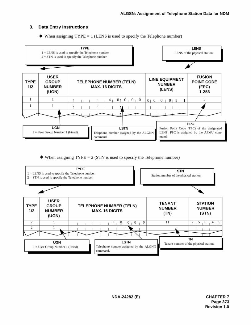
ALGSN: Assignment of Telephone Station Data for NDM
3. Data Entry Instructions
When assigning TYPE = 1 (LENS is used to specify the Telephone number)
When assigning TYPE = 2 (STN is used to specify the Telephone number)
TYPE1/2
USER GROUP
NUMBER(UGN)
TELEPHONE NUMBER (TELN)MAX. 16 DIGITS
LINE EQUIPMENT NUMBER (LENS)
FUSION POINT CODE
(FPC)1-253
1 1 5
1 1 4 0 0 0 0 0 0 0 0 1 1
TYPE1 = LENS is used to specify the Telephone number2 = STN is used to specify the Telephone number
LENSLENS of the physical station
UGN1 = User Group Number 1 (Fixed)
LSTNTelephone number assigned by the ALGNNcommand.
FPCFusion Point Code (FPC) of the designatedLENS. FPC is assigned by the AFMU com-mand.
TNTenant number of the physical station
TYPE1/2
USER GROUP
NUMBER(UGN)
TELEPHONE NUMBER (TELN)MAX. 16 DIGITS
TENANTNUMBER
(TN)
STATIONNUMBER
(STN)
2 1 11
2 1
4 0 0 0 0 2 5 6 4 5
TYPE1 = LENS is used to specify the Telephone number2 = STN is used to specify the Telephone number
STNStation number of the physical station
UGN1 = User Group Number 1 (Fixed)
LSTNTelephone number assigned by the ALGNNcommand.
NDA-24282 (E) CHAPTER 7Page 373
Revision 1.0

ALGSN: Assignment of Telephone Station Data for NDM
4. Data Sheet
a. LENS is used to specify the Telephone number (TYPE = 1)
TYPEUSER GROUP
NUMBER (UGN)
TELEPHONE NUMBER (TELN)
MAX. 16 DIGITS
LINE EQUIPMENT NUMBER (LENS)
FUSION POINT CODE(FPC)
1 1
1 1
1 1
1 1
1 1
1 1
1 1
1 1
1 1
1 1
1 1
1 1
1 1
1 1
1 1
1 1
1 1
1 1
1 1
1 1
1 1
1 1
1 1
1 1
1 1
1 1
1 1
1 1
1 1
1 1
1 1
1 1
1 1
CHAPTER 7 NDA-24282 (E)Page 374Revision 1.0

ALGSN: Assignment of Telephone Station Data for NDM
b. STN is used to specify the Telephone number (TYPE = 2)
TYPEUSER GROUP
NUMBER (UGN)TELEPHONE NUMBER (TELN)
MAX. 16 DIGITS
TENANT NUMBER
(TN)
STATIONNUMBER
(STN)REMARKS
2 1
2 1
2 1
2 1
2 1
2 1
2 1
2 1
2 1
2 1
2 1
2 1
2 1
2 1
2 1
2 1
2 1
2 1
2 1
2 1
2 1
2 1
2 1
2 1
2 1
2 1
2 1
2 1
2 1
2 1
2 1
2 1
2 1
2 1
NDA-24282 (E) CHAPTER 7Page 375
Revision 1.0

PBX AND ACD COMMAND PROGRAMMING
2.2 ACD COMMANDS
For NEAX2400 IMX Commands, see Section 2.1, “NEAX2400 IMX Commands” in this chapter.
Table 7-2 ACD Command List
COMMANDNAME
ICON DESCRIPTION
ACDTN Assignment of ACD Tenant Data
ACDSPL Assignment of ACD Split Data
ACDLOG Assignment of ACD Receiver ID Code
ACDPSN Assignment of ACD Position Data
ACDCCV Assignment of ACD CCV Data
ACDPLT Assignment of ACD Monitor Number
ACDTG Assignment of ACD Trunk Group Data
ACDANA Assignment of ACD Analog Split Access Code
ACDIVR Assignment of ACD IVR Data
ACDHS Assignment of ACD Holiday Schedule
ACDHC Assignment of ACD Holiday Calendar
ACDWS Assignment of ACD Week Schedule
ACDCOM ACD Communications Data
System Information System Information
ACD Backup ACD Backup
CHAPTER 7 NDA-24282Page 376Revision 1.0

PBX AND ACD COMMAND PROGRAMMING
2.2.1 Command Relationships
Each command consists of a name (four to six alphanumeric characters) which suggests its function and theparameters required for its execution. Table 7-3 describes the correspondence among the ACD and PBXcommands. Each ACD command may involve the assignment or execution of PBX commands and/or otherACD commands.
Each command description includes a section entitled “Assignment and Deletion Procedure” which describesthe correct sequence for applying related commands.
Table 7-3 Related Commands
Command NameRelated PBX (Non-Fusion)Commands
Related PBX FusionCommands
Related ACD Commands
ACDTN ASYD, ANPD, ASPA, AADTASYD, ANPDN, ASPAN,
ASYDL, AADTN, ASYDNACDCOM, ACDSPL,
ACDCCV
ACDSPL ACDTN
ACDLOG ACDTN, ACDSPL, ACDPSN
ACDPSNAEFR, ASFC, ASDT, AKYD,
ARSCAEFR, ASFC, ASDT, AKYD,
ARSCN, ALGSNACDSPL, ACDHS, ACDWS,
ACDHC, ACDTN
ACDCCV AADT, ASDT AADTN, ASDT, ALGSNACDSPL, ACDHS, ACDWS,
ADCHC, ACDTN
ACDPLT AMNO, ACNO, ASATAMNON, ACNON, ALGNN,
ASATNACDTN, ACDCCV, ACDWS
ACDTG ATRK, MBTK ALRTN ACDTN
ACDANA AMNO ALGNN, AMNON ACDPSN
ACDIVR ASDT, ASHU ASDT, ASHUN, ALGSN ACDTN
ACDHSACDTN, ACDWS, ACDHS,
ACDCCV
ADCHC ACDTN, ACDHS
ACDWS ACDTN, ACDCCV, ACDPLT
Total ACDSystem
ASYD (R), ASDT (R),AOKC (R), ARSC (R), ASFC (R), AKYD (R),
AMNO (R), ACNO (O), AEFR (R), AADT (O), ASHU (O), SPDL (R), ASAT (R), ROAI (O)
ASYD (R), ASYDL (R), ASDT (R), AOKC (R),ARSCN (R), ASFC (R),
AKYD (R), AMNON (R),ACNON (O), AEFR (R),
AADTN (O), ASHUN (O),SPDL (R), ASATN (R),ROAI (O), ALGNN (R)
ALRTN (R), ALGSN (R)
ACDTN (R), ACDSPL (R), ACDLOG (O), ACDPSN (R), ACDCCV (R), ACDPLT (R), ACDTG (R), ACDANA (O), ACDIVR (O), ACDHS (O), ACDHC (O), ACDWS (O)
(R) = Required, (O) = Optional
NDA-24282 CHAPTER 7Page 377
Revision 1.0

PBX AND ACD COMMAND PROGRAMMING
2.3 SETTING UP THE ACD
ACD parameters are set up in Windows 95 and Windows 98 using popup Windows. From the folder containingthe IMX installation/maintenance files, select the ACDMAT ACD MAT System option.
HouseSwitch - NECAM:IMXZ 1.5 -FPC 1
File View PBX Scan Help
MJ MN SUP TRF
ACDMAT ACD MAT System
System Control
System Backup
Make Busy Control
Traffic Data
Traffic Data for Fusion Network
Test
Station Data
Trunk Data
Numbering Plan
Service Feature Data
List Up Commands(1)
List Up Commands(2)
Signal Translation Data
Restriction Data
Installation
Local Data Memory
Event
Tool
Ready
CHAPTER 7 NDA-24282Page 378Revision 1.0

PBX AND ACD COMMAND PROGRAMMING
The IMX ACD MAT menu is displayed. Double-click the icon corresponding to the function you wish to set.
To identify the function, place the cursor on the icon. The name of the function is displayed.
Note: To use the ACD On-Line Help from any of the Windows, place the cursor in the box for the desired settingand press F1.
IMX ACD MAT
File View Options MAT Report Window Help
Ready
NDA-24282 CHAPTER 7Page 379
Revision 1.0

ACDTN: ASSIGNMENT OF ACD TENANT DATA
ACDTN: Assignment of ACD Tenant Data
1. Function
This command is used to assign, list, and print the following data for an ACD tenant:
[1] Tenant Number[2] Tenant Name (optional)[3] The number (maximum) of splits (per tenant)[4] Default Language[5] Operator Access Code[6] IVR Pilot Number[7] Outbound Answer Timer[8] Agent Personal Queue Parameters:
Announcement Number and Overflow/Forward Priority.
Tenant data gives the user an identity within the ACD system. It also allows the tenant to determine thenumber of splits that will be needed for ACD operations.
2. Precautions
1. The ACDTN data is one of the most important data for ACD system configuration. The user mustprogram the NSPL data carefully to lessen the need for future changes. If the NSPL data is changed,all data concerned with ACD function must be changed also.
2. Since data related to MIS connection is assigned using TN 1, the following data must be set even whenTN 1 is not used for the ACD system.TN=1, NSPL=1, PRI=1, LANG=0 *the data to be entered in other parameter is optional
3. For the maximum number of splits per ACD, see Section 2.3.1, “System Capacity” in Chapter 2.
4. Remove menu selection is not applicable for this command.
5. Assign the number of tenants for whole system including Business/Hotel features (SYS1, Index8).
Tenant Number: Name
Splits: IVR Plot Number Outbound Answer Timer:
Operator Access Code: Default Language:
1 ACD FPC40
5030
0 English
Agent Personal Queues
Announcement Number:
Overflow/Forward Priority:
1
1
I/O Port Assignment:
COM1 COM2COM3
Off MIS Infolink
Remove
List
Close
Tenant Data
Remove Tenant?
CHAPTER 7 NDA-24282Page 380Revision 1.0

ACDTN: ASSIGNMENT OF ACD TENANT DATA
3. Parameters
TENANT NUMBER: Tenant Number (1 to 10)NAME: Tenant Name (up to 20 characters)SPLITS: Maximum Split for Tenant (1 - 250)DEFAULT LANGUAGE: English
JapaneseSpanishItalianFrenchGerman
OPERATOR ACCESS CODE: Enter the operator access code programmed in the PBX subsystem(ASPA or ASPAN).
IVR PILOT NUMBER: Number to access IVR directory numbers used by ACDANSWER TIMER: Time (in seconds) after which an outbound call is assumed to have
been answered.AGENT PERSONAL QUEUE: Personal Announcement Number (0 - 58) or SPACE: feature not
usedOVERFLOW/FORWARD PRIORITY: Priority to use for split queuing after overflow or call forwarding
(1 to 250)I/O PORT ASSIGNMENT: MIS I/O Ports (1 to 6). Defines which of the MIS Ports are config-
ured for this tenant.
NDA-24282 CHAPTER 7Page 381
Revision 1.0

ACDTN: ASSIGNMENT OF ACD TENANT DATA
4. Assignment and Deletion Procedure
These flow diagrams show the procedure used to assign and change Tenant Data for the Integrated ACD.
Figure 7-1 Assigning and Removing Tenant Data Information
1
2
DESCRIPTION
1
2
1
1
START
ASYD
ACDTN
END
START
ACDTN
END
DESCRIPTION
Assign the number of tenants (SYS1 index 8).
Delete the Tenant data.
Assign the Tenant data.
CHAPTER 7 NDA-24282Page 382Revision 1.0

ACDTN: ASSIGNMENT OF ACD TENANT DATA
TenantNumber
(TN)1-10
Tenant Name(NAME)
Max. 20 characters
Numberof
Split1-250
DefaultLanguage
0-5
Access Codefor Operator
Call
Access Code of IVR(IVRNO)
OutboundAnswer Timer
(ANSTM)0-60
PersonalAnnouncement
Number(ANTNO)
0-58
Personal QueueOverflow/For-ward Priority
(PRI)1-255
NDA-24282 CHAPTER 7Page 383
Revision 1.0

ACDSPL: ASSIGNMENT OF ACD SPLIT DATA
ACDSPL: Assignment of ACD Split Data
1. Function
This command is used to assign, list, print, and remove ACD split data. Each split is configured throughthis command for its answer mode, after call status, conditional thresholds, and operationally-relateddirectory numbers and other split-related data.
2. Precautions
1. Directory number for assist, emergency, and night should be assigned before assigning split data.
2. The dictation trunk for emergency calls should be assigned before assigning split data.
3. The operation of Conditional Thresholds (COND) is shown in Table 7-4.
Note 1: If COND= NO CALLS ACCEPTED is selected, this split will not accept conditional Queue call.
Table 7-4 COND (Conditional Thresholds)
METHODS CONDITIONS RESULTS
No Calls Accepted No Call Accepted. Note 1 No conditional calls will be accepted by the split.
Agents Available Value: 1 to 250
Number of agents that must be available for conditional queue calls to be accepted. Note 2
Conditional calls will or will not be accepted.
Calls in QueueValue: 1 to 699
Will only accept conditional queue calls, depending on how many calls are already in queue to the split. Note 3
Conditional calls will or will not be accepted.
Dir NumbersNight
Assist:
Emergency
Recorder #
Split
Tenant Number Split: Name: Hot Split: Remove
List
Close
Split Data
R em o v e S p li t?
Dash
Recover Time:
Auto Answer:
Auto Ready After Call:
Require Tally Per Call:
Standard Calls CCV
Index:Step:
Upon PBX Call
Auto Work on Ring:
Auto Work on Answer:
Auto Work on Dial Out:
Auto Ready on Release:
Queue
Maximum Depth:
Agent Priority Queuing:
Queue When Vacant:
Work ModeRestricted:
TimeOut
While On PBX Call
Analog TimeOut
Conditional Threshold
Agents Available 1
Agent
Logoff Warning Criteria Jack Out Mode:
Require Logon ID: Multiple Break Types: Assist Key "Monitor
Call Waiting Thresholds
Light:Flash:
Chime:
CHAPTER 7 NDA-24282Page 384Revision 1.0

ACDSPL: ASSIGNMENT OF ACD SPLIT DATA
Note 2: If COND= AGENTS AVAILABLE is selected, then this split will accept Conditional Queue calls, dependingon the number of agents available in the split.Example: If “2” is entered as the number of agents that must be available in COND DETAIL, then therewill have to be at least 2 agents available in the split before it will accept any Conditional Queue calls.
Note 3: If COND= CALLS IN QUEUE is selected then the split will accept Conditional Queue calls depending onhow many calls are already in queue in this split.Example: If “3” is entered as the number of calls in queue in COND DETAIL and there are more than 3calls in queue, this split will not accept Conditional Queue Calls.
4. Handling of conditionally queued incoming ACD calls for a particular split. Refer to CCV steps (CallControl Vector Programming) for programming conditional call handling.
5. Logon IDs can be set either as required or not used in REQUIRE LOGON ID. If a logon ID is required,an agent must enter a logon ID before receiving access to the ACD system.
6. When the split is in the QUEUE WHEN VACANT mode (when no positions are logged on in the split),either the Queue or Do Not Queue option may be programmed.
7. The Assist key can be programmed on a split-wide basis to function as an Assist key or a Monitor Mekey in ASSIST KEY IS “MONITOR ME”.
8. Work mode can be Allowed or Restricted on a split-wide basis.
9. Call Waiting lamp can be programmed with two queue thresholds. It can light steadily when a specificnumber of calls are in queue, then flash when the second threshold of number of calls are in queue.
10. Never set the Call Waiting Threshold “LIGHT” and “FLASH” to the same value. Always set the“LIGHT” value lower than the “FLASH” value.
11. Work mode can be programmed to timeout after a position has been in Work mode for a predeterminedtime (on a split-wide basis).
12. Each split can be programmed to have one break mode type or nine break mode types in MULTIPLEBREAK TYPES.
13. QUEUE:The maximum number of calls that can be in queue at any given time. This field allows normal inputs(“150”) as well as “percentage” inputs (“150%”), used for Variable Depth Queuing. A Variable QueueDepth is one that changes based on the number of working agents (logged on and not in break mode).Therefore, with four working agents, a maximum depth of 150% would equate to 150% × 4 = 6 callsin queue. The seventh call would then not be allowed to queue until more working agents were addedto the split. Valid ranges for normal maximum depths are 1 to 700. Valid ranges for variable maximumdepths are 5% to 1000%, in increments of 5%.
14. Positions can be programmed to automatically go into Work mode if an outgoing call is made on thePBX line, or if an incoming call is received on the PBX line.Press SPACE BAR to change selection (No/Yes)
15. After-call work mode setting determines if an agent is available for the next call immediately, or if theagent is placed in an after-call work mode at the completion of the current ACD call.
NDA-24282 CHAPTER 7Page 385
Revision 1.0

ACDSPL: ASSIGNMENT OF ACD SPLIT DATA
16. Answer mode setting determines if a call is automatically connected following a zip tone or if the agentmust manually answer the incoming call by pressing the ANSWER key.
17. A split can be set up so that agent priority queueing can be used if desired.
18. This split can be set up as a Hot Split if desired.
19. A CCV can be assigned for calls stranded in queue.
20. The split can be programmed so that a call which rings at an agent’s phone for a long time can berecovered and requeued.
21. When assigning AUTO WORK ON RING or AUTO WORK ON DIAL OUT, do not set the WHILEON PBX CALL Time Out if the AUTO WORK MODE CANCEL Timer is to be restricted.
CHAPTER 7 NDA-24282Page 386Revision 1.0

ACDSPL: ASSIGNMENT OF ACD SPLIT DATA
3. Parameters
TENANT NUMBER: Tenant Number (1 to 10)SPLIT: Split Number (1 to 250)NAME: Split Name (Optional) - Up to 20 charactersREQUIRE LOGON ID: Required/Not RequiredAUTO READY AFTER CALL: Work / AvailableAUTO ANSWER: Automatic / ManualQUEUE: Maximum Queue Depth
1 ~ 7005 ~ 1000% (In increments of 5%).
CALL WAITING CHIME: No / YesJACK OUT MODE: Break / VacantWORK MODE TIMEOUT: 0~9999 seconds (0=indefinite)ASSIST KEY: Assist / Monitor MeMULTIPLE BREAK TYPES: 1 Break Type / 9 Break TypesDIR NUMBERS
NIGHT: Night Pilot Number (SPACE: feature not used)ASIST: Assistance Number (SPACE: feature not used)EMGCY: Emergency Number (SPACE: feature not used)RECORDER NUMBER: Recorder No. 1 ~ 5 or 0=feature not used
QUEUE WHEN VACANT: Queue / Do Not QueueWORK MODE RESTRICTED: Allow RestrictedUPON PBX CALL: Ring: Auto Work / No Auto Work
Answer: Auto Work / No Auto WorkDial: Auto Work / No Auto WorkRelease: Auto Work / No Auto Work
CONDITIONAL THRESHOLD: No Calls AcceptedAgent Available (1 ~ 250)Calls in Queue (1 ~ 699)
CALL WAITING THRESHOLD:Light (0 ~ 700)Flash (0 ~ 700)
STRANDED CALL CCV: Index number (1 ~ 900)Step number (1 ~ 20)
CALL RECOVER TIME: (1 ~ 255 seconds or 0=Feature Not Used)ANALOG WORK MODE TIMEOUT: 0 ~ 9999 seconds
0 = IndefiniteHOT SPLIT: No / YesAGENT PRIORITY QUEUING: Agent Queuing Options * Available since the PBX software Series 7400
and ACD software R3.Out of Service / In service
WORK MODE TIMEOUT: Allowed / RejectedREQUIRE TALLY PER CALL: Tally Required * * Available since the PBX software Series 7400 and
ACD software R3.Not required / Required
LOGOFF WARNING CRITERIA:Logoff Warning * Available since the PBX software Series 7400 andACD software R3.Disabled / Calls > Agents, number of calls in queue (1 ~ 9)
NDA-24282 CHAPTER 7Page 387
Revision 1.0

ACDSPL: ASSIGNMENT OF ACD SPLIT DATA
4. Assignment and Deletion Procedure
These flow diagrams show the procedure used to assign and delete ACD split data.
Figure 7-2 Assigning and Removing ACD Split Data
DESCRIPTION
1
2
1
2
1
1
START
ACDTN
ACDSPL
END
START
ACDSPL
END
DESCRIPTION
Assign the Tenant data.
Remove the Split data.
Assign the Split data.
CHAPTER 7 NDA-24282Page 388Revision 1.0

ACDLOG: ASSIGNMENT OF ACD RECEIVER ID CODE
ACDLOG: Assignment of ACD Receiver ID Code
1. Function
This command is used to assign, list, print, and remove logon data. Each agent logon identifies the user’stenant, name, language preference, and personal Pilot number information, as well as the splits (with theassociated priority level) the Logon ID is allowed to access, whether multisplit is allowed, and the personalassist and emergency numbers.
2. Precautions
1. Leading zeros are permitted in logon ID codes. A logon of 00127 is the same as 127.
2. Each split determines whether ID codes are required for logging on. (See ACDSPL command.)
3. An ID code may be used at only one position at any given time. Multiple logons with the same ID arenot permitted.
4. Position data (defined with the ACDPSN command) and logon data (defined with the ACDLOGcommand) are used to specify the valid logon/position mode combinations. Valid modes are: ACDPSN= Specified/Any. ACDLOG = Single Split, Any Split or Multiple Splits. See Table 7-5 in ACDPSNcommand for detailed information.
5. If using Abacus MIS, the logon ID cannot exceed four digits.
6. When Agent Queuing Options (see Splits - ACD [S-91A] in Chapter 5) is assigned in ACDSPL), thepriority is used as the agent’s preference level. If not, the value is used as the priority for taking callsterminated to multiple splits.
Split(s)
Any Split
????????
# Split #/Name Preference Attrb.
1 1FPRC 40-1 1
Remove
List
Close
Agent Logon
Remove Logon?
Logon
Tenant Number: Logon ID:Language:
Agent Name: Abbr. Name
Personal Overflow CCVOverflow Timeout:
Index:Step
:
Personal Queuing
Pilot Number:
Max Queue Depth:
Personal Forward CCV
Index:Step
:
Personal Numbers
Assist Request: Emerg Request:
NDA-24282 CHAPTER 7Page 389
Revision 1.0

ACDLOG: ASSIGNMENT OF ACD RECEIVER ID CODE
3. Parameters
TENANT NUMBER: Tenant Number (1 to 10)LOGIN ID: Consists of one to nine digits (1 to 999,999,999)NAME: (Optional) up to 14 charactersLANGUAGE: English
JapaneseSpanishItalianFrenchGerman
SPLITS: Available split to logon (1 - 250)PRIORITY: Priority for handling ACD calls in multiple splits/the agent’s preference
level (1 ~ 99)MULTI-SPLIT: Single/MultiPERSONAL PILOT NUMBER: Valid personal pilot number (SPACE: feature not used)
Queue depth for personal pilot number (0 ~ 999)PERSONAL FORWARD CCV: CCV index (1 - 900)
CCV step number (1 - 20)PERSONAL OVERFLOW CCV: 0 ~ 9999 seconds; 0 = indefinite
CCV index (1 - 900)CCV step number (1 - 20)
CHIME: Off/First/AllPERSONALASSIST: Individual assistance number or SPACE (SPACE: Functional not used)PERSONAL EMERG: Individual emergency number or SPACE (SPACE: Functional not used)NAMES: Abbreviated Name (Use all initials of the user.)
CHAPTER 7 NDA-24282Page 390Revision 1.0

ACDLOG: ASSIGNMENT OF ACD RECEIVER ID CODE
4. Assignment and Deletion Procedure
These flow diagrams show the procedure used to assign and delete ACD Agent Logon Data.
Figure 7-3 Assigning and Removing ACD Agent Logon ID Code
1
1
START
ACDLOG
END
START
ACDLOG
END
DESCRIPTION
DESCRIPTION
Assign the agent logon ID code (range 1 to 999999999).
Remove the ACD agent logon ID code.1
1
NDA-24282 CHAPTER 7Page 391
Revision 1.0

ACDPSN: ASSIGNMENT OF ACD POSITION DATA
ACDPSN: Assignment of ACD Position Data
1. Function
This command is used to assign, list, print, and remove ACD position data. Each position is identified bythe tenant it belongs to, the number of its ACD line and the PBX line it may have, and what split(s) theposition belongs to.
2. Precautions
1. The terms supervisor and agent are used as a convention but are not differentiated by the ACD.
2. Any position may have a NIGHT key.
3. Removing positions removes them as ACD agents or supervisors. Positions still function as PBX linesunless removed using ASDT (see NEAX2400 IMX Office Data Specifications).
4. If changing the Tenant Number, My Line number, or ACD line number with the ASDT/ASTNcommands (PBX), the position must first be deleted using the ACDPSN command before changes usingthe ASDT/ASTN commands may be made. See the procedure below:
STEP 1: Delete the ACDPSN data of ACD agent/supervisory position.STEP 2: Change the number using ASDT or ALGSL/ALGSNSTEP 3: Assign the changed number and other data in the ACDPSN data.
5. See Section 2.3.1, “System Capacity” in Chapter 2 for maximum number of ACD positions per ACD inthe IMX System.
6. If an invalid PBX or ACD line number is programmed in ACDPSN, it may cause erroneous CW lampproblems.
7. There should only be two lines on an ACD position (the My line and the ACD line). If other lines areprogrammed on an ACD position, the MIS status may be incorrect.
8. Do not allow Call Pickup to ACD lines (may cause incorrect MIS status).
Tenant Number:
Position Number:
ACD FPC40
Line Numbers
ACD:
PBX:
Split Assignment:
Any Split
Position Data
Remove Position?
Remove
List
Close
Allow Supervisor Tally-Ohs
Analog Agent Position
CHAPTER 7 NDA-24282Page 392Revision 1.0

ACDPSN: ASSIGNMENT OF ACD POSITION DATA
9. One of the following conditions must be met before using this command.
• ACD line number and PBX line number are assigned using the ASDT command• ACD line number and PBX line number are assigned using the ALGSL command
• ACD line number and PBX line number are assigned using the ALGSN command
10.The relationship between ACDLOG and ACDPSN is shown in Table 7-5.
3. Parameters
TENANT NUMBER: Tenant Number (1 to 10)POSITION NUMBER: Number of PBX Line (My Line) ACD NUMBER: Number of ACD Line [Virtual Line (maximum of five digits)]SPLIT ASSIGNMENT: Any or specified specific split
Split Number (1 ~ 250)(only used if SPLC=1)
ALLOW SUPERVISOR TALLY-OHS: Allow/Do Not AllowANALOG AGENT POSITION: No/Yes
Note: The List up program will scan both My-Line and ACD line positions within the range designated in the Listup command.
Table 7-5 Programming Considerations
LOGON TO A SPECIFIC SPLIT LOGON TO MULTIPLE SPLITS
ACDLOG
ACDPSN
MULTI-SPLIT=NO(Single logon)Max. 16 split is programmed in
ACDLOG
MULTI-SPLIT=NO(Single logon)
Any is programmed in ACDLOG
MULTI-SPLIT=YES(Multi logon)
Max. 16 split is programmed in
ACDLOG
MULTI-SPLIT=YES(Multi logon)
Any is programmed in ACDLOG
SPLITS
(SPECIFIED)
If Logon ID list contains the Specified Split in ACDPSN, the Agent will be ALLOWED to Logon to the system.
The Specified Split in ACDPSN will be ALLOWED to Logon to the system.
If one of the splits on the list is allowed by ACDPSN, ALL SPILITS ARE SERVICED.
Not valid, WILL NOT ALLOW LOGON to the system.
SPLIT
(ANY SPLITS)
System prompts for a Split, from ACDLOG. Agent must select one Split from the list.
Not valid, WILL NOT ALLOW LOGON to the system.
Will Allow Logon to the Splits allowed in ACDLOG.
Not valid, WILL NOT ALLOW LOGON to the system.
NDA-24282 CHAPTER 7Page 393
Revision 1.0

ACDPSN: ASSIGNMENT OF ACD POSITION DATA
4. Assignment and Deletion Procedure
These flow diagrams show the procedure used to assign and delete ACD Agent Position data.
Figure 7-4 Assigning and Removing ACD Position Data
1
2
3
1
2
3
1
2
3
1
2
DESCRIPTION
DESCRIPTION
Assign the station numbers for the ACD line and the PBX line. Assign the key data for the ACD position. Assign the position data.
Delete the ACD position data.
END
END
START
START
ASDT
AKYD
ACDPSN
ACDPSN
AKYD
ASDT 3
Delete the key data.
Delete the PBX and ACD line from station data.
CHAPTER 7 NDA-24282Page 394Revision 1.0

ACDCCV: ASSIGNMENT OF ACD CCV DATA
ACDCCV: Assignment of ACD CCV Data
1. Function
This command is used to assign, list, print, and remove Call Control Vectors. A Call Control Vector is a listof procedural instructions (or steps) for handling incoming ACD calls. The instructions defined by the CallControl Vector are sentence-based and can be combined to form many different sequences. Call ControlVectors provide the following functions for the ACD:
• Queue a call to a particular split.
• Pause for “n” seconds before continuing call processing.
• Announcement made during call processing (PBX and IVR).
• Hang up during call processing.
• Transfer to a particular directory number.
• Set a new priority or increase or decrease a call’s priority (new priority).
• Conditionally queue an incoming call to a particular split.
• Remove a call from a split’s queue (dequeuing).
• Queue to another split if the queue depth is full.
• Goto another CCV index step.
• Change priority of call at given point in the CCV.
• Skip a percentage of the calls going to the next step in the CCV.
• Conditionally perform next CCV instruction based on Estimated Time to Answer (ETA) of a call.
• Conditionally perform next CCV instruction based on ETA of a call in another split.*
• Individual IVR port number.*
• Delay the time for ringing start.*
* Available since the PBX software Series 7400 and the ACD software R3.
NDA-24282 CHAPTER 7Page 395
Revision 1.0

ACDCCV: ASSIGNMENT OF ACD CCV DATA
2. Precautions
1. GOTO steps should be used with caution to avoid programming an infinite loop.
2. When a call rings at an Agent’s position, the call will not continue through the CCV steps because thecall is considered complete.
3. Maximum number of splits which an incoming ACD call can be queued to (accomplished by anycombination of QUEUE TO and COND. QUEUE steps) is four/sixteen (before/after the PBX softwareSeries 7400 and ACD software R3).
4. A CCV can be used to define how an incoming call is handled at any time by programming the ACDWeek Schedule (ACDWS) and/or the ACD Holiday Schedule (ACDHS) commands.
5. It is recommended that the PAUSE step be programmed after an ANNOUNCEMENT step, and thatPAUSE be programmed at least as long as ANNOUNCEMENT.
6. The same CCV number cannot be assigned to multiple ACD tenant numbers.
7. The call is controlled by the CCV by programming multiple PAUSE steps. However, the total time ofmultiple PAUSE steps should not exceed 999 seconds in a CCV.
Call Control Vectors:
CCV Action Argument
1
2
3
4
5
6
7
8
9
10
Remove
List
Close
Call Control Vectors
Remove Logon?
Transfer Numbers
(1)
(2)
(3)
(4)
(5)
(6)
(7)
(8)
(9)
(10)
Tenant Number: CCV Index:
Changing a CCV while calls are in progress creates unpredictable results. CCV changes should bemade during low traffic periods. Alternatively, a new CCV can be created first and the pilot numbercan be changed to route to the new CCV.
CAUTION
CHAPTER 7 NDA-24282Page 396Revision 1.0

ACDCCV: ASSIGNMENT OF ACD CCV DATA
3. Parameters
ACDCCV TENANT NUMBER: 1 ~ 10CCV INDEX: 1 ~ 900CCV STEP: 1 ~ 20CCV ACTION: See Table 7-6.ARGUMENT: See Table 7-6.TRANSFER NUMBER: Each represents a PBX number with a maximum of 22 digits.
Table 7-6 CCV Parameters
ACTION ARGUMENT Remarks
0 Blank – Vacant for future use
1 Pause 1-999 sec. Waiting time before the next step
2Announcement Announce No. (1-58) Delay Announcement/Announcement
service in Night mode/Announcement service on holidays, etc.
3 GoTo CCV CCV INDEX and STEP For repeated use
4 Hang up – Forced to release
5Transfer to PBX Transfer Index Number (1 ~ 10) Ex. Dialed number of destination station in
the night mode
6 New Priority Queue number (1-250) Change the calls Priority
7
8 Conditional Queue Split number (1-250) Split number of destination Note 1
9 Dequeue From Split number (1-250) Dequeued from the originally called split Note 2
10 Queue to Split Split number (1-250) Will connect if Agent is available
11 End CCV – CCV is finished
12If Not Queued CCV Index and Step Number or
BusyWhen split queue is full, jump to the designate CCV no. or 0=Busy
13Skip Percent to skip (1-99) The next step is skipped at the rate of
designated percentage
14 IVR announcement Announcement No. (1-99) IVR announcement
15ETA less ETA threshold value (1-9999) When ETA value is less than the
predetermined threshold value, shift to the next step
16ETA greater ETA threshold value (1-9999) When ETA value is over the predetermined
threshold value, shift to the next step
17Ring Delay Delayed time to ringing (0-15
sec.)See “RING DELAY [R-145]”.
NDA-24282 CHAPTER 7Page 397
Revision 1.0

ACDCCV: ASSIGNMENT OF ACD CCV DATA
Note 1: For details of each parameter’s meaning, see Call Control Vector - ACD [C-108A] in Chapter 5.
Note 2: Valid for Overflow service.
18 Tally Short Tally No. Up to four digits This step will send Tally to MIS.
19 Tally Long Tally No. Up to eight digit This step will send Tally to MIS.
20IVRDN IVR Access number (maximum.
5 digits)* This step must be assigned before IVR
announcement.
21
Split ETA less “SPLIT” [Split number for ETA call processing (1 ~ 127)] and “ETA” [ETA threshold value in a specified split (1 ~ 511)] to be programmed Split ETA less)
When ETA value is less than the predetermined threshold value and in the predetermined split, shift to the next step.
22
Split ETA greater “SPLIT” [Split number for ETA call processing (1 ~ 127)] and “ETA” [ETA threshold value in a specified split (1 ~ 511)] to be programmed Split ETA greater)
When ETA value is greater than the predetermined threshold value and in the predetermined split, shift to the next step.
23 Up Priority A variable number Increase the Calls Priority by this amount.
Table 7-6 CCV Parameters
ACTION ARGUMENT Remarks
CHAPTER 7 NDA-24282Page 398Revision 1.0

ACDCCV: ASSIGNMENT OF ACD CCV DATA
4. Assignment and Deletion Procedure
These flow diagrams show the procedure used to assign and delete Call Control Vectors.
Figure 7-5 Assigning and Removing Call Control Vectors
WARNING:
1
2
3
4
1
2
3
5
1
2
3
4
5
4
5
END
END
START
START
AADT/AADTN
ASDT
ACDPLT
ACDSPL
ACDCCV
ACDCCV
ACDSPL
ASDT
AADT/AADTN
1
2
3
4
5
DESCRIPTION
Assign data for announcement trunks referenced by the CCV. Assign station data for any station referenced by the CCV. Assign a pilot number to go to the CCV or to a Week Schedule that references the CCV. Assign data for any splits referenced by the CCV. Assign the CCV.
Remove the CCV. Remove the split(s) referenced by the CCV. Remove the pilot number(s) that go to the CCV or to a Week Schedule that references the CCV. Remove the station data for any station referenced by the CCV. Remove the data for any announcement trunks referenced
ACDPLT
Some of these may not need to be deleted if being used by other Splits, CCV, etc.
by the CCV.
NDA-24282 CHAPTER 7Page 399
Revision 1.0

ACDPLT: ASSIGNMENT OF ACD MONITOR NUMBER
ACDPLT: Assignment of ACD Monitor Number
1. Function
This command is used to assign, list, print, and remove ACD pilot data. This consists of a pilot number thatdesignates the pilot to which ACD calls are routed and the Call Control Vector call processing path to betaken. Internal and Transfer Priorities can be designated as well as an optional pilot name.
2. Precautions
1. A Call Control Vector is a list of instructions describing the procedure to be used in handling anindividual call. Call processing steps are determined by the pilot number. Pilot numbers associate thecall processing procedure with a Call Control Vector. Additional information about CCV programmingcan be found under ACDCCV.
2. Pilot numbers should be assigned as monitored numbers (see AMNO or AMNON in this chapter).
3. Different pilot numbers can route to the same CCV or Week Schedule and use different priorities.
4. If an invalid pilot number is assigned, it may cause the Call Recover feature not to work.
5. For a maximum number of pilots in a ACD system, see Section 2.3.1, “System Capacity” in Chapter 2.
Note 1: Pilot Number is the same number programmed in AMNO or AMNON.
Note 2: Personal Pilot Numbers are not programmed in ADCPLT.
Alternate Night CCV
Index Step
:0 0
Pilot Data
Remove Pilot?
Remove
List
Close
Pilot
Tenant Number: Pilot Num: Name:
1 ACD FPC40 4399
Route to
Method: Index Step
:Call Control Vector 1 1
Priority
Internal: Trunk: Transfer:15 15 15
CHAPTER 7 NDA-24282Page 400Revision 1.0

ACDPLT: ASSIGNMENT OF ACD MONITOR NUMBER
3. Parameters
TENANT NUMBER: Tenant Number (1 to 10)PILOT NUMBER: The number used for the pilot in ACD call routingNAME: Pilot Name, up to 20 characters. ROUTE TO: Week Schedule (1-10)ROUTE TO: CCV index number (1-900)
CCV step number (1-20)ALTERNATE NIGHT CCV: Night CCV Index and Step NumberPRIORITY
TRUNK: Priority at which ACD trunk calls are queued (1 to 250).INTERNAL: Priority with which internal calls are queued (1 to 250).TRANSFERRED: Priority at which transferred calls are queued (1 to 250).
4. Assignment and Deletion Procedure
These flow diagrams show the procedure used to assign and delete ACD pilot data.
Figure 7-6 Assigning and Removing ACD Pilot Data
1
2
1
2
1
2
1
2
START
END
END
START
AMNO
ACDPLT
ACDPLT
AMNO
DESCRIPTION
DESCRIPTION
Assign the monitored number. Assign the pilot number.
Delete the pilot number. Delete the pilot number from the monitored number table.
NDA-24282 CHAPTER 7Page 401
Revision 1.0

ACDTG: ASSIGNMENT OF ACD TRUNK GROUP DATA
ACDTG: Assignment of ACD Trunk Group Data
1. Function
This command is used to assign, list, print, and remove ACD trunk group data. This data includes queuepriority, circuit quantity, and an optional trunk group name.
2. Precautions
1. If ACD circuits are not assigned, they will not report to the MIS.
2. Queue Priority for ACD trunk is programmed in ACDTG.
3. Parameters
TENANT NUMBER: Tenant Number (1 ~ 10) 0: indicates all tenantsTRUNK GROUP: Trunk Group Number (Rt. Number) (1 to 254)NAME: Trunk Group (Rt.) Name (optional, up to 20 characters).
Only 12 will show on ACD position.PRIORITY: Priority (1 to 250)TRK: Trunk Numbers (1 ~ 255)
Trunk GroupTenant Number: Trunk Group:
Name Priority:
1 ACD FPC40 1
1
Update
List
Close
Trunk Group Data
New Trunk Group
1 2 3 4 5 6 7 8 9 10
11 12 13 14 15 16 17 18 19 20
21 22 23 24 25 26 27 28 29 30
31 32 33 34 35 36 37 38 39 40
41 42 43 44 45 46 47 48 49 50
51 52 53 54 55 56 57 58 59 60
61 62 63 64 65 66 67 68 69 70
>< 1 - 70
CHAPTER 7 NDA-24282Page 402Revision 1.0

ACDTG: ASSIGNMENT OF ACD TRUNK GROUP DATA
4. Assignment and Deletion Procedure
These flow diagrams show the procedure used to assign and delete ACD trunk group data.
Figure 7-7 Assigning and Removing ACD Trunk Group Data
1
1
1
1
START
START
END
END
ACDTG
ACDTG
DESCRIPTION
DESCRIPTION
Assign the trunks as ACD circuits.
Remove the trunk group data.
NDA-24282 CHAPTER 7Page 403
Revision 1.0

ACDANA: ASSIGNMENT OF ACD ANALOG SPLIT ACCESS CODE
ACDANA: Assignment of ACD Analog Split Access Code
1. Function
This command is used to assign, list, print, and remove ACD Analog Agent access code data. These accesscodes enable agents using analog phones to perform many ACD features including logging on (with orwithout an ID), logging off, going into Ready, Work, and Break modes, entering tally codes, and reportingtrunk troubles.
2. Precautions
Analog access codes must be set up on the PBX as monitored numbers (see AMNO or AMNON in thismanual).
3. Parameters
ACCESS CODE: The dialed digit pattern used to invoke an ACD function.FEATURE: The ACD feature which this access code will provide. (1-13)
Logon With IDLogon Without IDLogoffReady ModeWork ModeBreak ModeTally CodeTrunk TroubleDay Mode SingleDay Mode AllNight Mode SingleNight Mode AllPermanent Work
LOGIN ID: The logon ID associated with an analog access code (only used for LOGON WITH ID).
TALLY CODE: The tally code associated with an analog access code(only used for TALLY CODE).
BREAK TYPE: The break type associated with an analog access code(only used for BREAK MODE).
Access Code Feature
Logon ID Tally Code
Logon Without IDUpdate
Close
List
Analog Agent Data
Break Type
Announcement
Success Failure
New Analog
CHAPTER 7 NDA-24282Page 404Revision 1.0

ACDANA: ASSIGNMENT OF ACD ANALOG SPLIT ACCESS CODE
ANNOUNCEMENTSUCCESS: Success Announcement or Tone
0 = Service Set Tone*1~58 = Announcement No. programmed in AADT. An agent will be connected to theannouncement upon successful operation.
FAILURE: Failure Announcement or Tone0 = Reorder Tone*1~58 = Announcement No. programmed in AADT. An agent will be connected to theannouncement upon failed operation.
Note: Valid since PBX software Series 7400 and ACD software R3.
Note: * or # are not available for access codes.
NDA-24282 CHAPTER 7Page 405
Revision 1.0

ACDIVR: ASSIGNMENT OF ACD IVR DATA
ACDIVR: Assignment of ACD IVR Data
1. Function
This command is used to assign, list, print, and remove ACD Interactive Voice Response Unit (IVR) data.This command sets up IVR ports which will be used to play customized announcements or obtain dialeddigit information from callers.
2. Precautions
IVR should be set up on the PBX as members of a UCD hunt group whose pilot number is the same as theIVR pilot number field of ACD tenant data (see ACDTN).
3. Parameters
TENANT: Tenant number (1 to 10)DIRECTORY NUMBER: The PBX directory number used to access an IVR port.PORT: The IVR port number associated with this directory number. (1-255)
DirectoryTenant Number
Port
Update
List
Close
IVR Data
CHAPTER 7 NDA-24282Page 406Revision 1.0

ACDIVR: ASSIGNMENT OF ACD IVR DATA
ACD IVR Integration Data Programming Sheet
Tenant Number(TN)
1 ~ 10
IVR Directory Number(IVR)
Up to 5
IVR Port Number(PORT)1 ~ 255
Remarks
NDA-24282 CHAPTER 7Page 407
Revision 1.0

ACDHS: ASSIGNMENT OF ACD HOLIDAY SCHEDULE
ACDHS: Assignment of ACD Holiday Schedule
1. Function
This command is used to assign, list, print, and remove the CCVs for holiday schedules. Up to threedifferent holiday schedules per tenant can be programmed for handling incoming calls. When a holiday isdesignated through the ACDHC command, calls are processed according to one of the three schedules forthat day. This only applies to Pilot Numbers that use time-of-week scheduling.
2. Precautions
Holiday schedules are only valid for pilot numbers using week schedule route.
3. Parameters
TENANT NUMBER: Tenant Number (1 to 10)SCHEDULE: Schedule Number (1 to 3)START TIMEHOUR: CCV start hour (0-23)MINUTE: CCV start minute (0-59)CCV INDEX: CCV index (1 to 900)CCV STEP: CCV step (1 to 20)
Start TimeCCV Index CCV Step
00:00 0 0
00:00 0 0
00:00 0 0
00:00 0 0
00:00 0 0
00:00 0 0
00:00 0 0
00:00 0 0
Update
List
Close
Holiday Schedules
New Holiday Schedule
Tenant Number
Schedule
ACD FPC401
1
CHAPTER 7 NDA-24282Page 408Revision 1.0

ACDHS: ASSIGNMENT OF ACD HOLIDAY SCHEDULE
4. Assignment and Deletion Procedure
These flow diagrams show the procedure used to assign and delete ACD Holiday Schedule data.
Figure 7-8 Assigning and Removing Holiday Schedule Information
1
2
3
1
2
3
1 1
DESCRIPTION
DESCRIPTION
Assign the Week Schedule.
Assign the Holiday Schedule.
Assign the Holiday Calendar data (schedule plus holiday)
Remove the Holiday Schedule data.
START
ACDWS
ACDHS
ACDHC
END
ACDHS
END
START
NDA-24282 CHAPTER 7Page 409
Revision 1.0

ACDHS: ASSIGNMENT OF ACD HOLIDAY SCHEDULE
ACD Tenant(TN)
1 ~ 10
Schedule Number1 ~ 3
CCV Start timeCCV Index
1 ~ 900CCV Step
1 ~ 20(HOUR)0 ~ 23
(MINUTE)0 ~ 59
1
2
3
CHAPTER 7 NDA-24282Page 410Revision 1.0

ACDHC: ASSIGNMENT OF ACD HOLIDAY CALENDAR
ACDHC: Assignment of ACD Holiday Calendar
1. Function
This command is used to assign, list, print, and remove Holiday Calendar information. The ACDHCcommand specifies days that calls are processed differently than on normal workdays (provided a HolidaySchedule is programmed). A Holiday Schedule only applies to pilot numbers that are using a WeekSchedule (ACDPLT). Holiday information includes a month and day entry and a number that refers to theHoliday Schedule to be used on that day. An unlimited number of days may be scheduled as holidays, andup to three different holiday schedules per tenant can be programmed. Holidays can be programmed up toone calendar year in advance.
2. Precautions
1. Holidays can be entered for any day of the year.
2. A separate Holiday Calendar is available for each tenant.
3. Parameters
TENANT NUMBER: Tenant Number (1-10)MONTH: Month (1-12)DAY: Day (1-31)SCHEDULE: Schedule Number (1-3)
Update
List
Close
Holiday Schedules
Remove Holiday Calendar?
Tenant Number
Schedule
ACD FPC401
1
Sun Mon Tue Wed Thu Fri Sat26 27 28 29 30 31 1
2 3 4 5 6 7 8
9 10 11 12 13 14 15
16 17 18 19 20 21 22
23 24 25 26 27 28 29
30 31 1 2 3 4 5
>< January 2000
NDA-24282 CHAPTER 7Page 411
Revision 1.0

ACDHC: ASSIGNMENT OF ACD HOLIDAY CALENDAR
4. Assignment and Deletion Procedure
These flow diagrams show the procedure used to assign and delete ACD Holiday Calendar data.
Figure 7-9 Assigning and Removing Holiday Calendar Information
1 1
1
2
3
1
2
3
DESCRIPTIONSTART
DESCRIPTION
ACDWS
ACDHS
ACDHC
END
END
START
ACDHC
Assign the Week Schedule.
Assign the Holiday Schedule.
Assign the Holiday Calendar.
Remove the Holiday Calendar.
CHAPTER 7 NDA-24282Page 412Revision 1.0

ACDHC: ASSIGNMENT OF ACD HOLIDAY CALENDAR
ACD Holiday Calendar Data Programming Sheet
ACD Tenant(TN)
1 ~ 10
Month and DaySchedule
1 ~ 3(MONTH)1 ~ 12
DAY
1
2
3
4
5
6
7
8
9
10
11
12
13
14
15
16
17
18
19
20
21
22
23
24
25
26
27
28
29
30
31
NDA-24282 CHAPTER 7Page 413
Revision 1.0

ACDWS: ASSIGNMENT OF ACD WEEK SCHEDULE
ACDWS: Assignment of ACD Week Schedule
1. Function
This command is used to assign, list, print and remove week schedule data. The ACDWS command is usedto program the CCV by which all incoming calls are handled on a 24-hour basis.
2. Precautions
1. CCVs should be assigned prior to use in week schedules.
2. For allowed number of entry for Week Schedule, see Table 2-1 in Chapter 2.
3. The same Schedule Number (SCH) can not be assigned to multiple tenant numbers.
3. Parameters
TENANT NUMBER: Tenant Number (1 to 10)SCHEDULE: Schedule Number (1 to 250)DAY: Sun, Mon, Tue, Wed, Thu, Fri, SatHOUR: CCV start time: hour (0-23)MINUTE: CCV start time: minute (0-59)CCV INDEX: CCV index (1 to 900)CCV STEP: CCV step (1 to 20)
Day TimeCCV
IndexCCV Step
1 00.00 0 0
2 00.00 0 0
3 00.00 0 0
4 00.00 0 0
5 00.00 0 0
6 00.00 0 0
7 00.00 0 0
8 00.00 0 0
9 00.00 0 0
10 00.00 0 0
Update
List
Close
Week Schedules
New Week Schedule
Tenant Number
Schedule
ACD FPC40
CHAPTER 7 NDA-24282Page 414Revision 1.0

ACDWS: ASSIGNMENT OF ACD WEEK SCHEDULE
4. Assignment and Deletion Procedure
These flow diagrams show the procedure used to assign and delete Week Schedule data.
Figure 7-10 Assigning and Removing Week Schedule Information
1
2
3
1
2
3
1
2
3
1
2
3
START
START
END
END
ACDPLT
ACDCCV
ACDWS
ACDWS
ACDCCV
ACDPLT
DESCRIPTION
DESCRIPTION
Delete the Week Schedule data for call processing. Delete the related CCVs. Delete the pilot number or change from routing to Week Schedule to a CCV.
Assign the pilot number to be routed to a Week Schedule.
Assign the CCV data for call processing.
Access Week Schedule data for call processing.
NDA-24282 CHAPTER 7Page 415
Revision 1.0

ACDWS: ASSIGNMENT OF ACD WEEK SCHEDULE
ACD Week Schedule Data Programming Sheet
Tenant Number (TN) 1 ~ 10
Schedule Number (SCH) 1 ~ 10
Day of week(WEEK)
Monday (MON)
Tuesday (TUE)
Wednesday (WED)
Thursday (THU)
Friday (FRI)
Saturday (SAT)
Sunday (SUN)
CCV start time (TIME)
CCV index 1 ~ 900
CCV step 1 ~ 20
CHAPTER 7 NDA-24282Page 416Revision 1.0

ACDCOM: ACD COMMUNICATIONS DATA
ACDCOM: ACD Communications Data
1. Function
This command is used to set up the I/O ports that are to be used for the Management Information Service(s)(MIS) and for Infolink.
2. Parameters
I/O Ports: 1 to 6I/O Type: MIS-1, MIS-2, MIS-3, MIS-4, MIS-5, Infolink, and OFFI/O Speed: 4-64 ms (standard assignment = 64)
Trace Parameters:Call Processing: On/OffMIS Errors: On/OffX409 Messages: On/Off
Trace Destination: I/O Port Number (1 to 6) / Buffer (Normally set to “Buffer”)Clock Adjustment: 1 to 9999 (default 1049)
3. Programming
The type of MIS will determine how the I/O ports are programmed.
• MIS-1: not supported
• MIS-2: Navigator and Abacus MIS
• MIS-3 ~ MIS-5: reserved for future use
• Infolink: for Infolink clients (ACD Release 3 and above)
I/O PortsType Speed
1
2
3
4
5
6
Update
List
Close
Communication Data
Update Communication?
Trace Parameters
Call Process-ing
MIS Errors
Trace Destination
Buffer I/O Port
Clock Adjustment
(Normally set to “OFF”)
NDA-24282 CHAPTER 7Page 417
Revision 1.0

SYSTEM INFORMATION
System Information
This screen sets the parameters for optimal functioning of the ACD in the IMX System. From the System Datascreen, User Settings, Tenant Settings and Time Out Settings are established. Using the system defaults for Userand Time Out Settings is highly recommended.
User Settings
1. Function
This command maintains the ACD’s system data for User Data. This data provides the ability to customizethe ACD for some specific features including Infolink and MIS message generation, debugging tools, andphone set operation.
Note: Using the system defaults for User Settings is highly recommended. Information on this screen should onlybe modified at the direction of a NEC Technical Support Associate.
2. Parameters
CCV Tally DN: 1-5 digitsSend A0 (MIS) Msg: Yes/NoDisplay ‘ANI NONE’: Yes/NoQueue High Priority: Yes/NoDisplay IVR Header: Yes/NoETA Includes Excess Work: Yes/NoInfolink with Call ID: On/Off (Default = Off)Time Out Audit: Yes/No
Dash
Min Len: Index 3:
Index 1: Index 4:
Index 2: Index 5:
7 11
5 0
8 0
User Settings Tenant Settings Time Out Settings
CCV Tally DN:
Send AO (MIS) Msg:
Display ’ANI NONE’:
Queue High Priority:
Display IVR Header:
ETA Includes Excess Work:
Infolink with Call ID:
Call Timeout Audit:
Orig Detail Codes:
Trim CP Trace Space:
Large CP Trace Buffer:
Incoming Cell Msg:
Outbound Cell Disp:
Reclaim IVR Call to:
Work Key Press:
MIS Split Capacity:
User Infolink Split Information:
IQ
IZ
Music
Ready Mo
4
Update
List
Close
System Data
Update System Data?
CHAPTER 7 NDA-24282Page 418Revision 1.0

SYSTEM INFORMATION
Orig Detail Codes: Yes/No (Default = No)Trim CP Trace Space: Yes/No (Default = No)Large CP Trace Buffer: Yes/No (Default = Off)
Dash Min Len: 1 to 16 (Default = 7)Index 1 ~ 5: 0 to 11
Incoming Call Msg: IQ or IqOutbound Call Disp: IZ or IzReclaim IVR Call to: Music/Ring BackWork Key Press: Ready Mode/Disable TimerMIS Split Capacity: 4/16 (Default = 4)Use Infolink Split Information: No/Yes
Tenant Settings
1. Function
This command maintains the ACD’s system data tenant table. If the system is required to accept calls fromtrunks/stations beyond the ACDTN range (1-10), this command allows the user to program these tenants.Note that if this table is used, all tenants from which ACD calls might originate (including tenants 1-10)must be programmed. As all ACD entities (splits, positions, etc.) must still reside in tenants 1-10, ACDTNmust still be programmed to provide the necessary tenant information.
2. Parameters
System Tenants: Highlight the number of the tenant to be updated, and select the Update option.
User Settings Tenant Settings Time Out Settings Update
List
Close
System Data
Update System Data?
1 2 3 4 5 6 7 8 9 10
11 12 13 14 15 16 17 18 19 20
21 22 23 24 25 26 27 28 29 30
31 32 33 34 35 36 37 38 39 40
41 42 43 44 45 46 47 48 49 50
51 52 53 54 55 56 57 58 59 60
>< System Tenants 1 ~ 60
NDA-24282 CHAPTER 7Page 419
Revision 1.0

SYSTEM INFORMATION
Time Out Settings
1. Function
This command maintains the ACD’s system data for time out information. It allows custom programmingof some timers used by the ACD. This data is critical to the operation of the ACD and should be modifiedwith extreme caution.
Note: Using the system defaults for Time Out Settings is highly recommended. Information on this screen shouldonly be modified at the direction of a NEC Technical Support Associate.
Agent Busy Loop Time: 5 to 15IVR Reclaim Retry Time: 3 to 10IVR Maximum Ring Time: 5 to 40Emergency Retry Time: 3 to 10Call Complete Delay: 3 to 15
Wait TimeAnnouncement: 2 to 10Called Release: 3 to 15Call Complete: 3 to 15Call Monitor: 2 to 10Call Monitor 1: 3 to 15Call Monitor 2: 3 to 15Connect Call: 3 to 15Connect Error Audit: 5 to 15Force Release: 3 to 15
Agent Busy Loop Time: Emergency Retry Time:
IVR Reclaim Retry Time: Call Complete Delay:
IVR Maximum Ring Time:
10 5
5 7
20
User Settings Tenant Settings Time Out Settings
Wait Time
Announcement: Force Release:
Called Release: Monitor:
Call Complete: OAI Release:
Call Monitor 1: IVR Reclaim Call:
Call Monitor 2: Call Recover:
Connect Call: Status Check:
Connect Error Audit:
4 7
7 10
7 7
4 7
7 7
7 7
10
Update
List
Close
System Data
Update System Data?
CHAPTER 7 NDA-24282Page 420Revision 1.0

SYSTEM INFORMATION
Monitor: 5 to 15OAI Release: 3 to 15IVR Reclaim Call: 3 to 15Call Recover: 3 to 15Status Check: 3 to 15
NDA-24282 CHAPTER 7Page 421
Revision 1.0
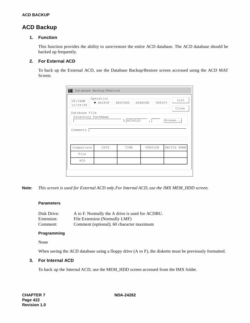
ACD BACKUP
ACD Backup
1. Function
This function provides the ability to save/restore the entire ACD database. The ACD database should bebacked up frequently.
2. For External ACD
To back up the External ACD, use the Database Backup/Restore screen accessed using the ACD MATScreen.
Parameters
Disk Drive: A to F. Normally the A drive is used for ACDBU.Extension: File Extension (Normally LMF)Comment: Comment (optional); 60 character maximum
Programming
None
When saving the ACD database using a floppy drive (A to F), the diskette must be previously formatted.
3. For Internal ACD
To back up the Internal ACD, use the MEM_HDD screen accessed from the IMX folder.
List
Close
Database Backup/Restore
08:54AM12/29/99
Comparison DATE TIME VERSION SWITCH NAME
File
ACD
OperationBACKUP RESTORE EXAMINE VERIFY
Database FileDirectory PathName
\ . ACD4LD2 Browse...
Comments
Note: This screen is used for External ACD only. For Internal ACD, use the IMX MEM_HDD screen.
CHAPTER 7 NDA-24282Page 422Revision 1.0

ACD BACKUP
Parameters
Select the following parameters and choose the Start option.
Memory to Hard Disk
ACD Data Memory
Direction Select
Memory to Hard Disk
Hard Disk to Memory
Verify HDD against MEM
Auto Verify Afterward
Data Type Select
Data Memory
Name Display
Wireless Call Forwarding
Call ForwardingLP Select
Speed CallingLP Select
User Assign KeyLP Select
Number SharingLP Select
ACD Data Memory
Call BackLP Select
✓
Start
Close
MEM_HDD Houseswitch
Processing Status Log
File View Help
MEM_HDD (Data control between Memory and HDD)
A c tio n / In fo rm a tio n D ire c t io n D ata T y p e
IN IT S E S S IO N
Note: This screen is used for Internal ACD only. For External ACD, use the Database Backup/Restore screen.
NDA-24282 CHAPTER 7Page 423
Revision 1.0

This page is for your notes.
CHAPTER 7 NDA-24282Page 424Revision 1.0

CHAPTER 8 SYSTEM OPERATIONS
1. GENERAL
This chapter explains the operating methods of the NEAX2400 CallCenterWorX-Enterprise ACD System.
• Operation of Dterm agent position/supervisory position
Log On/Log Off Answer Mode
Work Mode Break Mode
Tally Count Trunk Trouble Report
Call Transfer Night Service
Assistance Emergency/Recorder
Monitoring/Supervisory Override
• ACD system restart processing
For operation management, refer to the NEAX2400 IMX System Operations and Maintenance Manual.
NDA-24282 CHAPTER 8Page 425
Revision 1.0

SYSTEM OPERATIONS
2. OPERATION OF DTERM AGENT POSITION/SUPERVISORY POSITION
2.1 LOG ON/LOG OFF
Use the following procedures to start or end work by logging on or off.
(a) When ID Code is Required
Log On (Start of work)
When VACANT is displayed, press the LOG ON/OFF key.The lamp illuminates and LOG ON ID? is displayed.
Enter the ID code of the agent and press the # key.The dialed digits are displayed.HELLO XXXX (Agent Name) is displayed. The split name is displayed, then AUTO ANSWER or MAN ANSWER is displayed according to the program mode of the split to which the agent belongs, and WORK MODE is displayed.
Press the WORK key.READY is displayed.
Log Off (End of work)
Press the LOG ON/OFF key.The lamp goes out, the previous display disappears, and the following messages are displayed. (a) GOOD BYE XXXX (Agent Name: NAME in ACDLOG) (b) SHIFT 08:02:37 (The time since Log on in hours, minutes and seconds) (c) ACD CALLS 209 (The number of incoming calls handled)(d) AVG TALK 01:42.6 (The average time spent with each call in minutes, seconds and tenths
of a second)(e) T-WORK 01:23:45 (The cumulative amount of time spent in Work Mode during the shift in
hours, minutes and seconds)(f) T-BREAK 01:02:03 (The cumulative amount of time spent in Break Mode during the shift
in hours, minutes and seconds)
The display returns to VACANT.
END
START
CHAPTER 8 NDA-24282Page 426Revision 1.0

SYSTEM OPERATIONS
(b) When ID Code is not Required
Log On (Start of work)
When VACANT is displayed, press the LOG ON/OFF key.The lamp illuminates and HELLO is displayed. The split name is displayed, then, AUTO ANSWER or MAN ANSWER is displayed according to the program mode of the split to which the agent belongs, and WORK MODE is displayed.
Press the WORK key.READY is displayed.
Log Off (End of work)
Press the LOG ON/OFF key.The lamp goes out, the previous display disappears, and the following messages are displayed. (a) GOOD BYE (b) SHIFT 08:02:37 (The time since Log on in hours, minutes and seconds) (c) ACD CALLS 209 (The number of incoming calls handled)(d) AVG TALK 01:42.6 (The average time spent with each call in minutes, seconds and tenths
of a second)(e) T-WORK 01:23:45 (The cumulative amount of time spent in Work Mode during the shift in
hours, minutes and seconds) (f) T-BREAK 01:02:03 (The cumulative amount of time spent in Break Mode during the shift
in hours, minutes and seconds)
The display returns to VACANT.
END
START
NDA-24282 CHAPTER 8Page 427
Revision 1.0

SYSTEM OPERATIONS
2.2 ANSWER MODE
The following procedures are used to set the ACD call answering mode of each agent position to automatic ormanual.
(a) ACD Call Automatic Answer Mode
(b) ACD Call Manual Answer Mode
From the manual answer mode, press the AUTO/MAN key.The lamp lights and AUTO ANSWER is displayed. The agent enters the ACD call automatic answer mode. When an ACD call comes in, a zip tone is received. Monitor number name/Split name/Trunk group name, waiting time in the queue, and calling party’s number, etc. is displayed and the time to be spent for the conversation is indicated.
When the call is over, press the RELEASE key.
From the automatic answer mode, press the AUTO/MAN key.The lamp goes out and MANUAL ANSWER is displayed. The agent enters the ACD call manual answer mode.
When an incoming ACD call is terminated, press the ACD CALL key to answer it.Monitor number name/Split name/Trunk Group name, waiting time in the queue, and calling party’s number, etc. is displayed and the time to be spent for the conversation is displayed.
When the call is over, press the RELEASE key.
START
END
START
END
CHAPTER 8 NDA-24282Page 428Revision 1.0

SYSTEM OPERATIONS
2.3 WORK MODE
(a) Work mode manual setting
Use the following procedure to enter Work mode when the contents of the ACD call requires it.
(b) Work mode automatic setting
Use the following procedure if it is required to activate the Work mode automatically after every ACDcall.
Press the WORK key during communication with an ACD call. The lamp lights up and WORK PENDING is displayed.
Press the RELEASE key. WORK MODE is displayed, indicating the Work mode.
(End of work)
Press the WORK key.The lamp goes off and READY is displayed. Work mode ends, and the position becomes available for receiving the next ACD call.
Press the RELEASE key during communication with an ACD call.An incoming ACD call is completed. WORK MODE is displayed, indicating the Work mode.
(End of work)
Press the WORK key.The lamp goes off and READY is displayed.Work mode ends, and the position becomes available for receiving the next ACD call.
START
END
START
END
NDA-24282 CHAPTER 8Page 429
Revision 1.0

SYSTEM OPERATIONS
2.4 BREAK MODE
When it is required to leave the position unattended for a lunch or similar break, use the following procedure toactivate the Break mode in which the ACD call handling services can be interrupted temporarily.
(a) Set/reset during Communication with ACD Call
(b) Set/Reset when idle
Note 1: The period of time in break mode is displayed for 99 minutes and 59 seconds. When 99 min. and 59 sec.passes, the part of indicating “Minute” is displayed as “**”.
On handling an ACD call, press the BREAK key.The lamp lights and BREAK PENDING is displayed.
Press the RELEASE key.ON BREAK is displayed, indicating Break mode.
(Break)
Press the BREAK key.The lamp goes off, and ON BREAK OVER XX:XX (time spent on break in minutes and seconds) is displayed. Note 1Break mode ends, and the position becomes idle and available for receiving the next ACD call (READY is displayed).
Press the BREAK key.The lamp lights and ON BREAK is displayed
(Break)
Press the BREAK key.The lamp goes off, and BREAK OVER XX:XX (time spent on break in minutes and seconds) is displayed. Note 1Break mode ends, and the position becomes idle and available for receiving the next ACD call (READY is displayed).
START
END
START
END
CHAPTER 8 NDA-24282Page 430Revision 1.0

SYSTEM OPERATIONS
(c) Set/reset in Work Mode
Note 1: The period of time in break mode is displayed for 99 minutes and 59 seconds. When 99 min. and 59 sec.passes, the part of indicating “Minute” is displayed as “**”.
2.5 TALLY COUNT
Use the following procedure to collect data on the communication contents according to the types.
2.6 TRUNK TROUBLE REPORT
Use the following procedure to report trunk troubles, such as noise or low level, in the NEAX2400 IMX.
Press the BREAK key.The lamp lights and ON BREAK is displayed.
(Break)
Press the BREAK key.The lamp goes off, and BREAK OVER XX:XX (time spent on break in minutes and second) is displayed. Note 1Break mode ends, and the position returns to the Work mode (WORK MODE is displayed).
Press the TALLY key.The lamp lights and TALLY NUMBER? is displayed.
Dial the code number (1 to 9) of the subject, and press the # key.TALLY ENTERED is displayed. The lamp goes off, and the data is stored in the MIS.
During communication with an ACD call, press the TRK TRBL key.TROUBLE REPORTED is displayed. The Trunk Trouble Report is automatically reported to the MIS and MAT.
START
END
START
END
START
END
NDA-24282 CHAPTER 8Page 431
Revision 1.0

SYSTEM OPERATIONS
2.7 CALL TRANSFER
Use the following procedure to transfer an ACD call to another split.
2.8 NIGHT SERVICE
When the shift is over, the supervisory position can perform the following procedure to switch the entire splitinto the Night mode.
(a) From Day mode to Night mode
(b) From Night mode to Day mode
Press the XFER key.Special Dial Tone (SPDT) is heard.XFR (Dterm Series III) or XFR OPE (Dterm Series E) is displayed.
Dial the ACD monitoring number of the transfer destination split. The call is immediately connected to one of the idle stations in the transfer destination split.If all stations in the transfer destination split are busy, the transfer originator hears the Ring Back Tone (RBT) and should wait for an answering agent or release the call to complete the transfer.
The supervisor presses the NIGHT key.The lamp blinks, and ENTER NIGHT/FWD? is displayed.
Dial 1 followed by the # key. The lamp lights, and the split is switched to Night mode.New incoming calls are no longer queued, and calls which have already been queuing are connected as soon as an agent position becomes idle.
The supervisor presses the NIGHT key.The lamp blinks, and EXIT NIGHT? is displayed.
Dial 1 followed by the # key. The lamp goes out, and the split is switched to Day mode.
START
END
START
END
START
END
CHAPTER 8 NDA-24282Page 432Revision 1.0

SYSTEM OPERATIONS
2.9 ASSISTANCE
The agent position can request assistance from a supervisor during an ACD call.
2.10 EMERGENCY/RECORDER
The agent can notify the supervisory position of abnormal calls such as harassment and request monitoring. Ifa recorder is provided, the conversation can also be recorded.
Note: When the supervisor presses MON key while the agent is being monitored, “BARGE?” is displayed. At thattime, the supervisor may enter the conversation by pressing 1 + #.
The agent position presses the ASSIST key.ASSIST XXXX (Supervisory position name for the position with ID code or the ACD line number for the position without ID code) is displayed.
The supervisor answers the assistance call. ASSIST XXXX (Agent position name for the position with ID code or the ACD line number for the position without ID code) is displayed.
The supervisor and agent can confer while the ACD call is held with Consultation Hold.
The agent presses the EMER key.EMER XXXX (Supervisory name for the position with ID code or the ACD line number for the position without ID code) is displayed.If a recorder is provided, recording of the call starts at the same time.
The ACD CALL lamp and the MONITOR lamp on the supervisory position blink. When ringing starts, the supervisory confirms the display of EMER XXXX (Agent name or ACD line number), Trunk kind, Trunk number, and presses the LINE key. Note
The monitoring can be terminated when the supervisor presses the RELEASE key.The call between the ACD call and agent position continues. The recording ends.(When activating three-way conference, see 2.11 Monitoring/Supervisory Override)
START
END
START
END
NDA-24282 CHAPTER 8Page 433
Revision 1.0

SYSTEM OPERATIONS
2.11 MONITORING/SUPERVISORY OVERRIDE
With the following procedure, the supervisory position can monitor a conversation between an agent positionand ACD caller at any time, and can join the call by overriding if required.
3. ACD SYSTEM RESTART PROCESSING
Since the ACDP is incorporated in the NEAX2400 IMX, perform the restart procedure of the NEAX2400 IMXreferring to the “Installation Manual” or “System Operations and Maintenance Manual”.
Monitoring
Place Supervisor into the “Work” mode.
Supervisory presses the MON/BARGE key.The lamp blinks. MONITOR NUMBER? is displayed.
Dial the ID code of the agent to be monitored, or dial 0 followed by the non-ACD call station number of the agent position, and #.
(Monitoring)
Press MON/BARGE key again.BARGE? is displayed.
Supervisory Override
Dial 1 and #. The MON/BARGE lamp blinks.
(Three-way conference call between the ACD call, agent position and supervisory position).
Press the RELEASE or MON/BARGE key to end overriding.“CONF” lamp goes off and Return to Monitoring.
START
END
CHAPTER 8 NDA-24282Page 434Revision 1.0

CHAPTER 9 SYSTEM MAINTENANCE
1. GENERAL
This chapter explains the maintenance, diagnostics from system messages and fault recovery procedurerespectively of the NEAX2400 CallCenterWorX-Enterprise ACD System. If any fault has been discovered inthe course or as a result of maintenance operations, it should be diagnosed and repaired by referring to systemmessages concerned and the fault recovery procedure.
Figure 9-1 Flow of Maintenance Work
2. MAINTENANCE
3. SYSTEM MESSAGES Message Detail Data
System Messages for ACDP and MIS
4. FAULT DIAGNOSTICS Diagnostics from System Messages 5. FAULT RECOVERY PROCEDURE
MIS (1) MIS Restart Processing
Routine Maintenance
Daily Maintenance
NDA-24282 (E) CHAPTER 9Page 435
Revision 1.0

SYSTEM MAINTENANCE
2. MAINTENANCE
2.1 DAILY MAINTENANCE
The daily maintenance of the ACD System consists of the following checking.
Checking if the following system messages related to ACD system is displayed.
4-R: TCP/IP Link Failure
65-Q: ACD-MIS LOCK UP
6H: Bad Call Notification (ACD)
26-V: LAN Interface Error Report
2.1.1 THE RELATIONSHIP BETWEEN SYSTEM MESSAGES AND LAMP INDICATIONS
When the system has detected a fault, the corresponding system message is given and simultaneously, therelated lamp on the TOPU illuminates.
Table 9-1 shows the relationship between system messages and lamp indications.
Table 9-1 System Messages and Lamp Indications on the TOPU
SYSTEM MESSAGE LAMP ON THE TOPUREMARKS
NO. NAME MJ MN SUP NON
4-R TCP/IP Link Failure ×
5-Q ACD-MIS LOCK UP ×
6-H Bad Call Notification ×
26-V LAN Interface Error Report ×
CHAPTER 9 NDA-24282 (E)Page 436Revision 1.0

SYSTEM MAINTENANCE
3. SYSTEM MESSAGES
3.1 SYSTEM MESSAGES AND THEIR MEANINGS
The system messages shown in Table 9-2 is displayed when faults occur with the ACD within the IMX system.This table shows the system messages and their meaning.
Table 9-2 System Messages for MIS
SYSTEM MESSAGE
MEANING FAULT CONTENTS
4-R TCP/IP Link FailureA fault has occurred to the UAP or to the line connected with the external computer.
5-Q ACD-MIS LOCK UPAbnormal occurrence, and the communication between ACDP and MIS has locked up. (To be displayed when ASYD command, SYS 1, INDEX 42, b2 = “1”.)
6-H Bad Call Notification This message is issued to indicate the result of Bad Call Notification.
26-VLAN Interface Error Report
A fault, related to the TCP/IP connection between the PBX and MIS/HOST, occurred.
NDA-24282 (E) CHAPTER 9Page 437
Revision 1.0

SYSTEM MAINTENANCE
TCP/IP Lire
3.2 MESSAGE DETAIL DATA
This section describes the detailed information on the faults indicated by system messages (message detail data).
3.2.1 MESSAGE DETAIL DATA OF SYSTEM MESSAGE “4-R”
System Message 4-R: TCP/IP Link Failure
1. Print-out Format
2. Print-out information (typical)
When the PBX software Series 7300 and the ACD software R1 or earlier software are installed
Fault port number: 0-5Communication Protocol: 03 = ETHER + TCP/IPError Code (ERR): Refer to the table below
Note 1: This error code shows that the Host (UAP) is down manually. The option not to output this detail messageat some offices can be programmed using SYS1, INDEX864, b1 in ASYDL (Messages other than ERR = 01are output when TCP connection disconnected is not output).
Note 2: This data is output when using PBX software Series 7300 or earlier. If installing PBX software Series 7300or later, this information is output in the system message “26-V”.
PROTOCOL ERROR CODE CONTENT OF FAULT
03
(ETHER + TCP/IP)
01 TCP Connection disconnected (Normal) Note 1
02 Reception of a text which cannot be analyzed Note 2
03~09 Not used
10 (0A) TCP Connection disconnected (on the way) Note 2
11 (0B) Transmission to PZ-PC19 (LANI) is disabled (Permanent) Note 2
12 (0C) Abnormal UAP is detected by Heart Beat function
13 (0D) Not used
14 (0E) TCP/IP Connection Error (B-level Infinite Loop, etc.)
15 (0F) ~ 255 (FF) Not used
nk
SYSTEM MESSAGE 4 - R TCP/IP Link Failure NEC - ESD DEC 22 21:32
1: xx xx xx xx xx xx xx xx 2: xx xx xx xx xx xx xx xx 1 2 3 4 5 6 7 8 9 10 11 12 13 14 15 16
1
2
3
2 3
CHAPTER 9 NDA-24282 (E)Page 438Revision 1.0

SYSTEM MAINTENANCE
Fault logical channel number (LCID): 01~10H (00 means the data is invalid)
When the PBX software Series 7300 and the ACD software R2 or the later software are installed
Fault port number: 0-5Communication Protocol: 03 = ETHER + TCP/IPError Code (ERR): Refer to the table below
Note 1: This error code shows that the Host (UAP) is down manually. The option not to output this detail message at someoffices can be programmed using SYS1, INDEX864, b1 in ASYDL (Messages other than ERRK = 01 are output whenTCP connection disconnected is not output).
Fault logical channel number (LCID): 01~10H (00 means the data is invalid)
~ IP address
Relation between LCID and PBX TCP port number
LCID TCP port number of the PBX
01 60030
PROTOCOL ERROR CODE CONTENT OF FAULT
03
(ETHER + TCP/IP)
01 TCP Connection disconnected (Normal) Note 1
12 (0C) Abnormal UAP is detected by Heart Beat function13 (0D) ~ 255 (FF) Not used
Relation between LCID and PBX TCP port number
LCID TCP port number of the PBX
01 60030
4
1
2
3
2 3
4
5 8
NDA-24282 (E) CHAPTER 9Page 439
Revision 1.0

SYSTEM MAINTENANCE
: ACD-MK UP
3.2.2 MESSAGE DETAIL DATA OF SYSTEM MESSAGE “5-Q”
System Message 5-Q: ACD-MIS LOCK UP
This message is output when the PBX software release 5 and the ACD software release 1 or the later softwareare installed.
(1) Print-out Format
(2) Print-out information (typical)Each data is always displayed as “0”.
IS
SYSTEM MESSAGE 5 - Q ACD-MIS LOCK UP NEC - ESD MAY 11 22:30
1: 00 00 00 00 00 00 00 00 2: 00 00 00 00 00 00 00 00
CHAPTER 9 NDA-24282 (E)Page 440Revision 1.0

SYSTEM MAINTENANCE
Bad CficationD)
3.2.3 MESSAGE DETAIL DATA OF SYSTEM MESSAGE “6-H”
System Message 6-H: Bad Call Notification (ACD)
1. Print-out Format
2. Print-out information (typical)Bad Call Notification
20=ACD trunk connectionACD Trouble Kind
01=ACD trunk trouble key14=ACD reset start15=Insufficient ACD memory16=Insufficient ACD call record17=Excessive business station on ACD calls18=Excessive calls queued21=Unknown Pilot No. called24=Illegal execution of ACD timeout procedure30=ACD pointer error detection and recovery33=ACDP reset completion34=Call recovery failure on unknown Pilot No.37=ACD Traffic (incoming) Capacity Over Note99=Illegal ACD processing - trace stored
Note: Since the PBX software Series 7300 and the ACD software release 2.
[When = 01 (Hex)]~ : Information on Calling Party
– Station~ : My Line No. (Station): 00
– Trunk~ : Route No.~ : Trunk No.
~ : 00 00~ : Information on Calling Party
– Station~ : Station No.: 00
– Trunk~ : Route No.~ : Trunk No.
all
SYSTEM MESSAGE 6 - H BAD CALL NOTIFICATION NEC - ESD AUG 14 17:00
1: xx xx xx xx xx xx xx xx 2: xx xx xx xx xx xx xx xx 1 2 3 4 5 6 7 8 9 10 11 12 13 14 15 16
1
2
2
3 6
3 5
6
3 4
5 6
7 8
9 12
9 11
12
9 10
11 12
NDA-24282 (E) CHAPTER 9Page 441
Revision 1.0

SYSTEM MAINTENANCE
~ : Information on Held Party or 3rd Station/Trunk in 3-party connection– Station
~ : Station No.: 00
– Trunk~ : Route No.~ : Trunk No.
[When = 14 (Hex)]: Issue of ACDP (First digit of decimal place): Issue of ACDP (Second digit of decimal place)
[When =21 (Hex)]~ : Information on Calling Party
– Station~ : My Line No. (Station): 00
– Trunk~ : Route No.~ : Trunk No.
~ : 00 00~ : Information on Unknown Pilot No.
– Station:~ : Unknown Pilot No. called: 00
[When = 24 or 99 (Hex)]~ : 00 00 00 00~ : Error Counter
[When = 30 (Hex)]~ : Pointer Address: 00: Error Kind
[When = 33 (Hex)]: ACDP Data Memory: 00=Used
01=Not used: ACDP System Capacity: 02=50 Agent Positions
04=200 Agent Positions07=500 Agent Positions12=900 Agent Positions15=2,000 Agent Positions
[When = 34 (Hex)]~ : Information on Unknown Pilot No.
~ : Unknown Pilot No. called: 00
13 16
13 15
16
13 14
15 16
2
3
4
2
3 6
3 5
6
3 4
5 6
7 8
9 12
9 11
12
2
3 6
7 8
2
3 6
7
8
2
3
4
2
3 6
3 5
6
CHAPTER 9 NDA-24282 (E)Page 442Revision 1.0

SYSTEM MAINTENANCE
3. Bad Call Notification Codes.
Print code Tally-Oh Ref. No. Description
2001 Auto-print Trunk Trouble key
2002 (Removed)
2003 03 Caller abandon during agent ringing
2004 04 Direct call to agent’s ACD line
2005 05 Call connect failed, requeued
2006 06 Call connect failed, dropped after multiple attempts (Bad calling party)
2007 07 Call re-connect attempt
2008 08 Call connect error audit loop
2009 09 Agent force logoff (via Tally-Oh code)
2010 10 Supervisor forced agent to logoff (via Tally-Oh code)
2011 11 Supervisor forced agent to Break (via Tally-Oh code)
2012 12 Supervisor forced agent to Ready (via Tally-Oh code)
2013 13 Supervisor forced agent to Work mode (via Tally-Oh code)
2014 Auto-print ACD initialization started
2015 Auto-print Insufficient ACD memory
2016 Auto-print Insufficient ACD call records
2017 Auto-print Excessive business stations, agent PBX lines, and Att’s. on ACD calls
2018 Auto-print Excessive calls queued
2019 (Reserved)
2020 (Reserved)
2021 Auto-print Unknown pilot number called
2022 22 Count free call records (once per hour if enabled)
2023 23 Invalid tenant specified for agent
2024 Auto-print Illegal execution of ACD time-out procedure
2025 25 Pilot number illegally removed (not by MAT)
2026 26 Attendant called pilot without held party
2027 27 Position audit corrected locked agent (enabling turns on audit)
2028 28 Call record audit corrected locked call record (enabling turns on audit)
2029 29 Call recovered
2030 Auto-print Pointer corruption detected and corrected
2031 31 Call abandoned while on hold
2032 32 Count total number of incoming messages (once per hour if enabled)
2033 Auto-print ACD initialization complete
2034 Auto-print Recover call failure due to bad pilot number
2099 Auto-print Illegal ACD process, trace stored
NDA-24282 (E) CHAPTER 9Page 443
Revision 1.0

SYSTEM MAINTENANCE
4. Auto-Print and Tally-Oh Codes
Some Bad Call Notifications are always printed on the MAT because of their importance. These codes aremarked as Auto-print in the above table. All codes not marked Auto-print are turned off when ACD is ini-tialized, but can be manually turned on using the Tally-Oh code 075. To use, press the Tally key on any agentor supervisor phone and enter:
• 075;
• the two-digit reference number listed in the above table;
• either 0 (Off) or 1 (On);
• the # key.
For example, to turn on the Bad Call Notification print-out for “Call Recovered,” press TALLY 075291#.
To change all Bad Call Notifications, use the reference number 00. For example, pressing TALLY 075000turns off all codes.
5. Examples
• Agent 4031 reported trunk trouble while connected to route 134, trunk 10, with the held station 4302.
1: 20 01 4A 31 00 00 00 00 2: 01 34 00 1A 43 A2 00 00
• Route 5 trunk 14 abandoned after ringing 72 seconds at agent position 5432.
1: 20 03 54 32 00 00 00 72 2: 00 05 00 14 00 00 00 00
• Station 4003 has placed a direct call to the ACD line on station 5144.
1: 20 04 51 44 00 00 00 00 2: 4A A3 00 00 00 00 00 00
• An attempt to connect route 7 trunk 3 to agent 6640 has failed. Caller is being re-queued.
1: 20 05 66 4A 00 00 00 00 2: 00 07 00 03 00 00 00 00
• Successive attempts to connect route 3 trunk 15 have failed. Caller was dropped.
1: 20 06 00 00 00 00 00 00 2: 00 03 00 15 00 00 00 00
• A second attempt is being made to connect route 3 trunk 15 to agent 5677.
1: 20 07 56 77 00 00 00 00 2: 00 03 00 15 00 00 00 00
• A connection attempt to agent 2002 has failed. Checking agent for valid status.
1: 20 08 2A A2 00 00 00 00 2: 00 00 00 00 00 00 00 00
• Agent 78300 used Tally-Oh code to forcibly logoff.
1: 20 09 78 3A A0 00 00 00 2: 00 00 00 00 00 00 00 00
• Supervisor 3888 used Tally-Oh code to force logoff of agent 3005.
1: 20 10 3A A5 00 00 00 00 2: 38 88 00 00 00 00 00 00
• Supervisor 3888 used Tally-Oh code to force agent 3005 into break mode.
1: 20 11 3A A5 00 00 00 00 2: 38 88 00 00 00 00 00 00
• Supervisor 3888 used Tally-Oh code to force agent 3005 into ready mode.
1: 20 12 3A A5 00 00 00 00 2: 38 88 00 00 00 00 00 00
CHAPTER 9 NDA-24282 (E)Page 444Revision 1.0

SYSTEM MAINTENANCE
• Supervisor 3888 used Tally-Oh code to force agent 3005 into work mode.
1: 20 13 3A A5 00 00 00 00 2: 38 88 00 00 00 00 00 00
• The ACD has started the initialization process of release 2.12. Last initialization (prior to this one) wason September 25 at 7:15 pm. This msg will be followed by the number 33 ACD Initialization Completemsg.
1: 20 14 02 12 00 00 00 00 2: 00 00 00 00 00 00 00 00
• The ACD has exhausted available memory, new trunks will not be accepted.
1: 20 15 00 00 00 00 00 00 2: 00 00 00 00 00 00 00 00
• The ACD has exhausted available call records, new calls will receive ring-back tone.
1: 20 16 00 00 00 00 00 00 2: 00 00 00 00 00 00 00 00
• The ACD has exhausted available station records, additional ACD calls from business stations, agentPBX lines, or attendants will not be accepted.
1: 20 17 00 00 00 00 00 00 2: 00 00 00 00 00 00 00 00
• The ACD has exhausted available queue records, additional queueing of ACD calls will not be pro-cessed.
1: 20 18 00 00 00 00 00 00 2: 00 00 00 00 00 00 00 00
• Route 9 trunk 2 called the monitored number 4359, which is not listed as a pilot number in the ACDdatabase.
1: 20 21 00 09 00 02 00 00 2: 43 59 00 00 00 00 00 00
• This is a count of available call records. The ACD could accept 293 more calls. Printed once per hour,on the hour.
1: 20 22 00 00 00 00 02 93 2: 00 00 00 00 00 00 00 00
• Invalid ACD tenant. Agent 3211 has a different tenant between ACD and PBX.
1: 20 23 32 11 00 00 00 00 2: 00 00 00 00 00 00 00 00
• Internal ACD sequence error. This error has now been reported 7 times.
1: 20 24 00 00 00 00 00 07 2: 00 00 00 00 00 00 00 00
• The pilot number 4350 was illegally removed by the ACD. (Does not include removal from the MAT)
1: 20 25 43 5A 00 00 00 00 2: 00 00 00 00 00 00 00 00
• Attendant 2 called pilot number 4350 without a held party.
1: 20 26 20 00 00 00 00 00 2: 43 5A 00 00 00 00 00 00
• Position audit found agent 4301 in a bad state and corrected it. The position’s state was #14 and it waspointing to a call record containing route 9 trunk 2, and 4302. The position audit is turned on by enablingthis printout. The audit does not run otherwise.
1: 20 27 43 A1 00 00 00 14 2: 00 09 00 02 00 00 43 A2
• Call record audit found a call record in a bad state and corrected it. The three parties in the call recordwere 4301, 4350, and route 52 trunk 7. The call record audit is turned on by enabling this printout. Theaudit does not run otherwise.
1: 20 28 43 A1 00 00 00 00 2: 43 5A 00 00 00 52 00 07
NDA-24282 (E) CHAPTER 9Page 445
Revision 1.0

SYSTEM MAINTENANCE
• Call was recovered after ringing too long at an agent’s ACD line. The ringing time can be set with theACDSPL MAT command. The agent was 4301, the ringing time was 45 seconds, the split number was2, the calling party was station 5800, and the held party was route 17 trunk 4.
1: 20 29 43 A1 00 00 45 02 2: 58 AA 00 00 00 17 00 04
• The ACD detected corruption in the list of critical pointers. The pointer was 8000:1234 and the corrup-tion type was #2. The corruption has been corrected and should not cause future problems.
1: 20 30 80 00 12 34 00 02 2: 00 00 00 00 00 00 00 00
• An ACD call released from an agent while on hold. The agent was 4301, three minutes and 20 secondshave elapsed since the caller was put on hold, and the caller was route 15 trunk 7.
1: 20 31 43 A1 00 00 03 20 2: 00 15 00 07 00 00 00 00
• Count of incoming messages from the PBX to the ACD. This printout will be done once an hour, on thehour. There are 10 counters, each of which count messages for 6 minute blocks. In the first 6 minutesof the hour, there were (hex) 482B messages. There were (hex) A655 messages in the second 6 minutes,etc. This is used primarily for determining a relative traffic count.
1: 20 32 2B 48 55 A6 1C 56 2: 3F 62 98 B0 26 4D EF 78
• ACD initialization completed. This message will follow the #14 ACD Initialization Started msg.
1: 20 33 00 00 00 00 00 00 2: 00 00 00 00 00 00 00 00
• Recover Call failed due to a bad pilot number. When a call is recovered from an agent position afterringing the specified amount of time, the caller is reconnected to the first pilot number in the ACD da-tabase until another agent becomes available. If this pilot number is bad (doesn’t exist in the PBX data-base, etc.), the recover will fail and this message will be printed. In this case, the pilot number 4350 isbeing reported. The pilot number should be removed or reprogrammed correctly.
1: 20 34 43 5A 00 00 00 00 2: 00 00 00 00 00 00 00 00
• Internal ACD error. Trace snapshot saved in buffer. 27th occurrence of this error.
1: 20 99 00 00 00 00 00 27 2: 00 00 00 00 00 00 00 00
CHAPTER 9 NDA-24282 (E)Page 446Revision 1.0

SYSTEM MAINTENANCE
: LAface Err
ort
3.2.4 MESSAGE DETAIL DATA OF SYSTEM MESSAGE “26-V”
System Message 26-V: LAN Interface Error Report (OAI/MIS)
This message is output when the PBX software Series 7300 and the ACD software release 2 or the later softwareare installed.
1. Print-out Format
2. Print-out information (typical)
- TCP/IP Part -~ IP address of the error-detected OAI/MIS terminal~ Port No.
Used socket No.Error Code (TCP/IP part)
- Application Part -Application Type05=OAI07=MISFaulty Logical Port No.Error Kind (ERR)01=SEND Execution Error02=RECEIVE Execution Error03=TCP/IP Connection Error04=Connection Error (B-level Infinite Loop, etc.)05=TCP/IP Port Capacity Over
Nor
SYSTEM MESSAGE 26 - V LAN INTERFACE ERROR REPORT NEC - ESD JULY 25 19:30
1: xx xx xx xx xx xx xx xx 2: xx xx xx 00 00 00 00 00 1 2 3 4 5 6 7 8 9 10 11 12 13 14 15 16
TCP/IP Part Application Part
1 4
5 6
7
8
9
10
11
NDA-24282 (E) CHAPTER 9Page 447
Revision 1.0

SYSTEM MAINTENANCE
4. FAULT DIAGNOSTICS
4.1 FAULT INFORMATION AND FAULT DIAGNOSTICS
Alarms are indicated or system messages are displayed if errors occur within the NEAX2400 IMX CallCenterWorX-Enterprise (ACD) system. By collecting fault information promptly, the fault can be diagnosed andrecovery operations can be started quickly. Figure 9-2 shows the flow from the occurrence of a fault to itsdiagnostics.
Figure 9-2 Flow from Fault Occurrence to Fault Diagnostics
Fault Occurrence
Fault Information Collection
• Alarm
• System Message
• Fault detected during routine
maintenance
4.2 Diagnostics from System
Messages
CHAPTER 9 NDA-24282 (E)Page 448Revision 1.0

SYSTEM MAINTENANCE
4.2 DIAGNOSTICS FROM SYSTEM MESSAGES
Figure 9-3 shows the operations from the diagnostics based on system messages to the identification of the causeof fault.
Figure 9-3 Flow of Diagnostics from System Message
Diagnostics from System Message
Determination of Faulty Circuit Card or Equipment
Identifies the cause of fault by analyzing the displayed system message4-R “TCP/IP Link Failure” – See Sections 4.2.1 and 3.2.1.5-Q “ACD MIS LOCK UP”6-H “Bad Call Notification” – See the “NEAX2400 IMX System Operations andMaintenance Manual”.26-V “LAN interface Error Report” – See Sections 4.2.1 and 3.2.3.
For other messages, refer to the “NEAX2400 IMX System Operations and MaintenanceManual”.
When an alarm, such as circuit card initialization, is displayed during diagnostics, pressthe ALM RST button to reset the alarm indication.
When the result of diagnostics shows that the fault is temporary, execute the “RALM”command to reset all alarms and system messages and supervise the system operation.
Go to Section 5, “Fault Recovery Procedure”
When the cause of fault is identified, perform the fault recovery procedure in Section 5, which isshown inside of the diagnostics procedures.
NDA-24282 (E) CHAPTER 9Page 449
Revision 1.0

SYSTEM MAINTENANCE
4.2.1 TCP/IP LINK FAILURE
For details of System Massage “4-R” and “26-V”, see Section 3.2.1 and Section 3.2.3 in this Chapter.
According to each fault situation, perform the repairing procedure referring to the table below.1. When the PBX software Series 7300 and the ACD software R1 or the earlier software are in-
stalled.
Host is still in abnormal status?Host is out of order. Repair the Host computer. PZ-PC19 (LANI) card is out of order. For the replacement procedure, see the “NEAX2400 IMX System Operations and Maintenance Manual”.
START
If yes,If no,
2. When the PBX software Series 7300 and the ACD software R2 or the later software are in-stalled.
3. When Message, “26-V” is displayed:
Table 9-3 Repairing Procedure for TCP/IP Link Failure (Message “4-R”) (1/2)
ERR Detail information of ERR Check Item
01TCP/IP connection is down for the TCP connection disconnection ordered from Host.
Restart the Host
0CAccording to Heart Beat function of Host, abnormal status of the Host system operation is detected.
Check system operation of the Host
0D Not used
0ETCP port is released due to the detection of abnormal state in the TCP/IP part (such as B-level Infinite Loop. etc.)
Re-check the operation status of Host.
0F~FF Not used
Table 9-3 Repairing Procedure for TCP/IP Link Failure (Message “4-R”) (2/2)
ERR Detail information of ERR Check Item
01TCP/IP connection is down for the TCP connection disconnection ordered from MIS or IVR/Host.
Restart the MIS or IVR/Host
0CAccording to Heart Beat function of MIS or IVR/Host, abnor-mal status of the MIS or IVR/Host system operation is detected.
Check system operation of the MIS or IVR/Host
0D~FF Not used
Table 9-4 Repairing Procedure for TCP/IP Link Failure (Message “26-V”)
ERR Error Situation Check Item
01
TCP/IP connection is down because the text is not transmitted continuously.
[1] Check the TCP/IP Transmission capacity on the UAP side is proper or not.
[2] Check on the operation status on the UAP side is normal.
02
Incorrect text format is received. [1] Check the software operation on the Host side.
[2] Check the LAN cable connection status.
03TCP/IP connection is released due to the TCP port disconnection order from the Host.
Re-start the Host computer.
04TCP port is released due to the detection of abnormal state in the Host operation.
Re-check the operation status of Host.
05
TCP/IP connection cannot be established due to the connection port capacity over.
The number of allowed ports for application use via TCP/IP must be 16 or less. Adjust the total port number within this range.
CHAPTER 9 NDA-24282 (E)Page 450Revision 1.0

SYSTEM MAINTENANCE
4.2.2 BAD CALL NOTIFICATION
Perform the diagnostic work followed by “System Operations and Maintenance Manual”.
5. FAULT RECOVERY PROCEDURE
5.1 BEFORE STARTING FAULT RECOVERY
After the fault diagnostics based on fault information such as the alarm and system messages, the next procedureto be done is the fault recovery. Before proceeding to this, it is required to examine when it should be started bycomparing the emergency of repair and its influences. Particularly, when the fault is determined in the ST-BYsystem, the work should be done at night when the ACD system is operated less frequently. The fault recoveryprocedures can be divided into those on the ACD system and those on the MIS, as shown below.
Figure 9-4 Flow of Fault Recovery Procedures
5.2 ACD SYSTEM FAULT RECOVERY PROCEDURES
See the “NEAX2400 IMX System Operations and Maintenance Manual” for the fault recovery procedurerelated to the ACD system shown below.
Fault information Collection
ACD System Fault Recovery – MIS Fault Recovery –See Section 5.2 See Section 5.3
Section 4.2, “Diagnostics from System Messages”
1. ACDP of Fault - Fault occurs intermittently at ACT side
2. ACDP of Fault - ST-BY side is faulty
NDA-24282 (E) CHAPTER 9Page 451
Revision 1.0

SYSTEM MAINTENANCE
5.3 MIS FAULT RECOVERY PROCEDURES
This paragraph describes the fault recovery procedures related to the MIS in the order shown below.
1. MIS Restart Processing
Step 1: By selecting MIS System Stop, cause the MIS to cease operating.
Step 2: Turn off the power supply to the MIS. After 5 ~ 6 seconds, turn on the power supply again.
Step 3: The MIS starts up.
Step 4: Perform operation tests of the MIS.
2. Check on Connection Cables
Check to see if the cable is connected between the MIS and the NEAX2400 IMX.
CHAPTER 9 NDA-24282 (E)Page 452Revision 1.0

APPENDIX A GLOSSARY
ACD Automatic Call Distribution.
ACDP Automatic Call Distribution Processor. (For the NEAX2400 IMX, the ACDP isbuilt in the CPU of the PBX)
ACD line Virtual line of an ACD position.
ACD MAT Maintenance Administration Terminal (MAT) on which the ACD commands areloaded.
After call mode Selection of ACD position availability after ACD call completion. In Work mode,an ACD position becomes unavailable to receive ACD calls upon release from theprevious ACD call. In Available mode, an ACD position becomes available toreceive ACD calls upon release from the previous call.
Agent Personal Queue Queues for calls that are directed to a specific ACD position.
Answer mode Answer mode for ACD positions: either Auto or Manual. In Manual mode,incoming calls ring at the position and are required to be answered manually. InAuto mode, calls are connected using the headset or handset, and are introduced bya Zip Tone.
Auto Work mode Occurs when the ACD position receives or places a call on the PBX line.
Call Control Vector (CCV) A list of instructions or steps for handling incoming ACD calls.
Circuits The number of trunks in a trunk group that are designated as ACD trunks.
Conditional threshold Threshold values set for call acceptance of conditional queue calls into the queueof a target split.
Default language The language that will be shown on the display of an ACD position that is loggedonto the ACD system.
Directory number Night, Assist and Emergency destination programmed in split data (ACDSPL).
Do Not Disturb Occurs when none of the ACD positions of an ACD split are logged on.
Hardware type Specifies if the position is a Dterm or analog agent.
Holiday A date designated as a holiday within the ACD system, subject to holiday callhandling procedures (see ACDHC and ACDHS).
I-ACD Integrated ACD.
I/O type Defines which type of MIS or Infolink will be used on the input/output port.
Infolink A data communications link between the ACD system and external computerequipment such as host and IVRs.
Internal priority Priority at which an internal call will be handled.
IVR Interactive Voice Response unit. A voice prompting unit that can be guidedthrough menus via DTMF signalling.
Language Language to be used for ACD terminal display (Dterm).
Logon ID ID code used to logon to the ACD system.
NDA-24282 APPENDIX APage 453
Revision 1.0

GLOSSARY
Logon required Specifies whether ID entry is required for an ACD position to gain access to theACD system.
MAT Maintenance Administration Terminal.
Maximum queue depth The number of calls that can be placed in queue.
MIS Management Information System.
MIS I/O port Designates the I/O port(s) used for MIS.
PBX line The My Line of an ACD position.
Pilot number A number used for routing calls to a CCV or a Week Schedule.
Queue priority Priority at which a trunk call is placed in queue to a split.
Route To Defines the routing method for pilot number, such as CCV or Week Schedule. (SeeACDCCV and ACDWS.)
Split A hunt group of ACD positions.
Splits Allowed Specifies which splits a position can take calls from.
Tenant A software delineation between multiple groups that share a PBX or ACD system,e.g., multiple companies which share the same switch, or separate divisions of onecompany that share an ACD systems.
Tenant name Name associated with the occupant or user of an ACD system.
Tenant number Number associated with the occupant or user of an ACD system.
Transfer priority Priority at which a transferred call will be handled.
Trunk group Route number associated with ACD.
Week schedule A schedule consisting of a list of CCVs to be used in routing calls when the WeekSchedule method of routing has been designated. (See ACDWS, ACDPLT, andACDCCV commands.)
APPENDIX A NDA-24282Page 454Revision 1.0

APPENDIX B FIELD VALUES FOR ACD SCREENS
Table B-1 Field Values for ACD Screens (1/8)
FIELD NAME DESCRIPTION VALUESDEFAULT SETTING
REQUIRED/OPTIONAL
ACD Line Line that receives all of the ACD calls for this position (via pilot numbers). (Virtual line)
Up to 5 digits
none required
After call mode
The state the position will be in after finishing a call from this split. If available mode is selected, the position will become available immediately upon disconnect from the previous call. If work mode is selected, the position will go into work mode.
available/work
available required
Agent priority queueing
Determines whether to use priorities when queueing available agents.
Priorities/No
Priorities
NoPriorities
required
Alternate night destination CCV
Specifies the CCV to use for the pilot number’s alternate night destination.
Index:0 ~ 900(0 = not
used)Step: 1 ~ 20
0 optional
Analog agent access code
Number that invokes an ACD feature for an analog agent. up to 5 digits
none required
Analog agent break type
Break type to be associated with an analog agent access code.1 ~ 9 none optional
Analog agent feature
The feature associated with an analog agent access code. Possible values are: Logon with ID, Logon without ID, Logoff, Ready Mode, Work Mode, Break Mode, Tally Code, Trunk Trouble.
(see list at left)
none required
Analog agent logon ID
Logon ID of agent or supervisor. up to 9 digits
none optional
Analog agent tally code
Tally code associate with the dialed analog agent access code. up to 9 digits
none optional
Analog agent work mode timeout
The maximum time (in seconds) that an analog agent can stay in Work mode. (0 = indefinite.) 0 ~ 9999 0 optional
Analog position
Specifies whether this position is analog or not.Yes/No No optional
NDA-24282 APPENDIX BPage 455
Revision 1.0

FIELD VALUES FOR ACD SCREENS
Answer mode Determines how the position can answer ACD calls for this split. If Manual is selected, the position must answer calls manually by pressing the Answer button or the ACD Line key. If Auto is selected, calls are connected automatically; the position will hear Zip Tone when a new call is connected.
manual/auto
manual required
Assist directory number
The directory number that will be dialed when an agent presses the Assist button while on an ACD call.
Up to 5 digits
none optional
Assist key is: Defines the function of the Assist key. Assist/Monitor
Assist required
Auto work mode for IC PBX
Automatic work mode, which removes the position from receiving ACD queued calls while receiving an incoming call on the PBX line.
Yes/No No required
Auto work mode for OG PBX
Automatic work mode, which removes the position from receiving ACD queued calls while placing an outgoing call on the PBX line.
Yes/No No required
Break type Specifies whether agents should be prompted for break type when entering Break mode.
1 (no prompt)/
9 (prompt)
1 required
Call recover time
Sets the amount of time (in seconds) an ACD call can ring at an agent position before being recovered. (0 = feature not used)
0 ~ 255 0 optional
Call waiting chime (ACDLOG)
Defines how the call waiting chime will function for personal queue calls. Off = no chime. First = chime will sound for the first call placed in queue. All = chime will sound for each call placed in queue.
Off/First/All
Off required
Call waiting light threshold
The minimum number of calls in queue to this split before the call waiting lamp will light steadily.
0 ~ 999 (0 = off)
0 optional
Call waiting flash threshold
The minimum number of calls in queue to this split before the call waiting lamp will flash.
0 ~ 999 (0 = off)
0 optional
CCV index The index (reference number) to a specific CCV. 1 ~ 900 none required
Table B-1 Field Values for ACD Screens (2/8)
FIELD NAME DESCRIPTION VALUESDEFAULT SETTING
REQUIRED/OPTIONAL
APPENDIX B NDA-24282Page 456Revision 1.0

FIELD VALUES FOR ACD SCREENS
CCV step One of up to 20 steps in a Call Control Vector. (See ACDCCV command for details.) Possible steps are listed below.
See below none required
ACTION ARGUMENT DESCRIPTIONQueue To split number Offer the call to the splitDequeue From split number Stop offering the call to the splitConditional Queue split number Offer the call to the split if it meets a conditional thresholdIf Not Queued Go To CCV index and step If the split queue is full, go to Busy or specified CCV index and
stepGo To CCV index and step Go to the specified CCV index and stepTransfer To 1 ~ 10 Route the call to a number (up to 22 digits)New Priority priority (1 ~ 250) Change the call’s priority to the specified valueUp Priority amount (1 ~ 250) Change the call’s priority by the specified amountAnnouncement number (1 ~ 58) Route the call to an announcementHang Up — Disconnect the callPause seconds (1 ~ 999) Pause before performing the next stepEnd — End of CCVSkip percentage (1 ~ 99) Skip percentage to next stepIVR Announcement number (1 ~ 99) Connect call to IVR for customized announcementIndividual IVR IVR access number Individual IVR port number in a CCV step basisETA Less seconds (1 ~ 9999) Do next step if estimated time to answer is less than specified
timeETA Greater seconds (1 ~ 9999) Do next step if estimated time to answer is greater than specified
timeETA Less in a split (1 ~127)/ Do next step if estimated time to answer is less than specifiedspecified split seconds (1 ~ 511) time in a specified splitETA Greater in a split (1 ~127)/ Do next step if estimated time to answer is greater than specifiedspecified split seconds (1 ~ 511) time in a specified splitRing Delay seconds (1 ~ 15) Delay time to start ringing for the next incoming call
Chime (ACDSPL)
Call Waiting chime that sounds when the call waiting threshold is met.
On/Off Off required
Conditional threshold method
Method for accepting calls into the split:• No Calls Accepted: no calls are accepted into the queue.• Agents Available: calls are accepted depending on the
number of available positions.• Calls in Queue: calls are accepted depending on the num-
ber of unanswered calls in queue.
No Calls/Agents
Available/Calls in Queue
No Calls Accepted
required
Conditional threshold value
Value used in conjunction with the method (described above):• Agents Available: the number of positions that must be
available before calls will be accepted.• Calls in Queue: the least amount of unanswered calls in the
queue before calls will be accepted.
1 ~ 250(Agents
Available)1 - 699
(Calls inQueue)
none optional
Table B-1 Field Values for ACD Screens (3/8)
FIELD NAME DESCRIPTION VALUESDEFAULT SETTING
REQUIRED/OPTIONAL
NDA-24282 APPENDIX BPage 457
Revision 1.0

FIELD VALUES FOR ACD SCREENS
Default language
The language used on a logged-off ACD position. English/Japanese/Spanish/Italian/French/German
English required
Do Not Disturb
Specifies how ACD calls will be handled when there are no positions logged onto the split.
Queue/Do Not Queue
Queue required
Emergency directory number
The directory number that will be dialed when the agent presses the EMERGENCY button while on an ACD call.
up to 5 digits
none optional
Emergency recorder number
Number of the recorder that will be connected to the call in progress when an agent requires and emergency recording to be made.
0 ~ 5(0 = none)
0 (none) optional
File comment (remark)
Any supplementary remarks you wish to be associated with the file.
up to 60 characters
none optional
Go to CCV (forward/full)
Defines action (CCV index and step) to be taken if the referenced logon ID is not logged on the system (forward), or if the personal queue is full (full).
CCVindex
(1 ~ 900)and step (1 ~ 20)
none optional
Go to CCV (overflow)
Defines action (CCV index and step) to be taken when there is an overflow timeout.
CCVindex
(1 ~ 900)and step (1 ~ 20)
none optional
Holiday CCV list
A list of entries to be followed when a Holiday Schedule is used. Each entry consists of a start time and a CCV index and step.
Time (HH:MM)
CCVindex and
step
none optional
Holiday date The month and day that is defined as a holiday. Date MM/DD
none optional
Holiday schedule number
Reference number for a holiday schedule.1 ~ 3 none optional
Hot split Specifies whether this split is to be used for hot positions. Yes/No No optional
Internal priority
Priority that a station call will receive when queued within the local system, when presented to the pilot number.
1 (high) ~ 250 (low)
15 required
Table B-1 Field Values for ACD Screens (4/8)
FIELD NAME DESCRIPTION VALUESDEFAULT SETTING
REQUIRED/OPTIONAL
APPENDIX B NDA-24282Page 458Revision 1.0

FIELD VALUES FOR ACD SCREENS
IVR directory number
The PBX directory number that allows ACD to access a port on an Interactive Voice Response (IVR) unit.
up to 5 digits
none required
IVR pilot number
The PBX directory number used by ACD to access ports on an Interactive Voice Response (IVR) unit.
up to 5 digits
none required
IVR port number
Associates a port on the IVR unit with the IVR directory number.
required
Language The language a position’s messages will be displayed in when a position is logged on.
English/Japanese/Spanish/Italian/French/German
English required
Logon ID The agent’s ID code used when logging on to the ACD system.
up to 9 digits
none required
Logon ID is ? Used to control access to the split. Required/Not Used
Required required
Logon Name The name to be displayed when logging on with a logon ID. Displayed on ACD position’s display.)
up to 20 characters
blank optional
Max. queue depth
The maximum number of calls that can be queued to this split or personal pilot number.
1 ~ 999 99 required
Multi-split Defines whether this logon ID has access to multiple splits simultaneously.
Yes/No No optional
Night directory number
The directory number to which calls will be routed when the split is in Night mode. (Must be a valid pilot number.)
up to 5 digits
none optional
Operator access code
Defines the access code programmed for the operator in the PBX database.
up to 5 digits
0 required
Outbound call answer timer
Time allowed for outbound calls to be considered successfully completed
0 ~ 60 sec-onds
30 required
Overflow timeout
Defines how long a call will stay in queue to the personal pilot number before it overflows. (0 = Indefinite.)
0 ~ 9999 none required
PBX incoming
Specifies whether agents should be forced into Work mode upon receiving an incoming call on their PBX line.
Yes/No No required
PBX outgoing Specifies whether agents should be forced into Work mode upon receiving dial tone for an outgoing call on their PBX line.
Yes/No No required
Personal assist request number
Overrides the assist request number programmed in ACDSPL.
up to 5 digits
none optional
Table B-1 Field Values for ACD Screens (5/8)
FIELD NAME DESCRIPTION VALUESDEFAULT SETTING
REQUIRED/OPTIONAL
NDA-24282 APPENDIX BPage 459
Revision 1.0

FIELD VALUES FOR ACD SCREENS
Personal emergency request number
Overrides the emergency request number programmed in ACDSPL. up to 5
digitsnone optional
Personal pilot number
Defines the number programmed in AMNO/AMNOL/AMNON. (Not programmed in ACDPLT.)
up to 5 digits
none optional
Personal queue announcement number
Defines the announcement used for calls directed to personal queue (for the entire tenant).
1 ~ 58 none optional
Personal queue overflow/forward priority
Defines the priority for calls that overflow from a personal queue.
1 ~ 250 1 optional
Pilot name Name displayed when a call is answered at positions. up to 20 characters
blank optional
Pilot number (ACDPLT)
A directory number that calls can be presented to. (Personal pilot numbers are not programmed here.)
up to 5 digits
none required
Position The My Line of the ACD position. up to 5 digits
none required
Queue priority
Priority at which a call from this trunk group (route) is placed in the queue.
1 (high) ~ 250 (low)
1 required
Route to: Method used to route a call when presented to this pilot number. Options are:• CCV: index and step number• Week Schedule: reference number
CCV index
(1 ~ 900) and step (1 ~ 20)/
week schedule (1 ~ 10)
CCVindex 1, step 1
required
Split name Name displayed at positions at logon time. up to 20 characters
blank optional
Split number Number that references a split. 1 ~ 250 1 required
Split priority Used when assigning calls to agents in multi-split mode. 1 ~ 250 1 required
Splits (ACDTN)
Maximum number of splits assigned to this tenant.1 ~ 250 1 required
Table B-1 Field Values for ACD Screens (6/8)
FIELD NAME DESCRIPTION VALUESDEFAULT SETTING
REQUIRED/OPTIONAL
APPENDIX B NDA-24282Page 460Revision 1.0

FIELD VALUES FOR ACD SCREENS
Splits (ACDLOG)
Designates what splits are allowed. All, or up to 4
different splits
All required
Splits allowed (ACDPSN)
Number of splits allowed to position. 1 ~ 250 or Any
1 required
Stranded calls CCV index
Designates the CCV index to use when recovering stranded calls. (0 = not used.)
0 ~ 900 0 optional
Successful feature activation announcement
Specifies the announcement to be connected to an analog agent notifying that a feature activation was successful. (0 = none.) 0 ~ 58 0 optional
Supervisor tally-oh codes
Specifies whether this position is allowed to use supervisor Tally-Oh codes.
Allow/Do Not Allow
Do Not Allow
optional
Tenant name Name printed at the top of reports. up to 20 characters
blank optional
Tenant number
Reference number for the tenant.1 ~ 10 none required
Transfer priority
Priority of a transferred call when presented to a pilot number. 1 (high) ~ 250 (low)
15 required
Transfer numbers
Digits to be dialed for each “Transfer To” CCV step that references this number. Only digits 0 ~ 9 are allowed. This is only required when there is a “Transfer To” step referencing it.
up to 22 digits
blank optional
Trunk group name
Name to be displayed when a call is answered at an ACD position.
up to 20 characters
blank optional
Trunk group number
Number that references a trunk group (route).1 ~ 254 1 required
Trunk circuits Used for activating/deactivating the trunk’s circuits as ACD circuits (trunks).
1 ~ 255 1 to 1 required
Trunk priority The priority used when queueing ACD trunk calls to a pilot number.
1 (high) ~ 250 (low)
1 required
Week schedule CCV list
A list of entries to be followed when a week schedule is used. Each entry consists of a start time and the CCV index and step to be followed.
Time (HH:MM)
CCV index and
step number
none optional
Table B-1 Field Values for ACD Screens (7/8)
FIELD NAME DESCRIPTION VALUESDEFAULT SETTING
REQUIRED/OPTIONAL
NDA-24282 APPENDIX BPage 461
Revision 1.0

FIELD VALUES FOR ACD SCREENS
Week schedule number
Number that reference a week schedule.1 ~ 10 1 required
Work mode A mode that exempts the agent/position from receiving ACD calls in queue without logging out. Restricted or allowed on a per-split basis.
Allow/Restrict
Allow required
Work mode timeout
Total time that an ACD position will be allowed to stay in Work mode. (0 = indefinite.)
0 ~ 9999 seconds
0 optional
Table B-1 Field Values for ACD Screens (8/8)
FIELD NAME DESCRIPTION VALUESDEFAULT SETTING
REQUIRED/OPTIONAL
APPENDIX B NDA-24282Page 462Revision 1.0

APPENDIX C ACD SERVICE IN FUSION NETWORK
The table below shows Available or Not Available for each ACD feature described in Chapter 5 when those servicesare activated between two fusion nodes within a Fusion Network.
Table C-1 ACD Service List in Fusion Network
: Available, × : Not available, – : Not applicable
FEATURE CODE
SERVICE NAME
FCCS
Series 7300
(Release 5) or earlier
Series 7300
(Release 7) or later(Note)
A-31A Abandoned Call Search - ACD –
A-34A Assistance - ACD Agent - ACD ×
A-35A Automatic Answer - ACD –
A-37A Availability - ACD Position - ACD –
A-80A Announcements - ACD
A-85A Agent Personal Queue - ACD
A-86A Auto Work Mode for PBX Calls - ACD –
A-91A Analog ACD Position - ACD ×
A-93A Alternate Night CCV - ACD
A-133A Agent Anywhere - ACD ×
B-20A Break Mode - ACD –
B-21A Bad Call Notifications - ACD –
C-35A Call Distribution to Agents - ACD ×
C-67A Call Transfer to Split Queue - ACD ×
C-68A Call Waiting Indication - LCD Display/CW Lamp - ACD –
C-70A Calling Party Identification - ACD –
C-108A Call Control Vector - ACD – –
C-110A Call Waiting Lamp with Chime - ACD –
C-127A Call Forwarding - Split - ACD
C-191A Call Recover - ACD –
C-199A Connection Displays - ACD –
D-133A Do Not Disturb - Split - ACD –
E-6A Emergency/Recorder - ACD ×
Note: When the “AGENT ANYWHERE” data is programmed.
NDA-24282 APPENDIX CPage 463
Revision 1.0

ACD SERVICE IN FUSION NETWORK
F-10A Function Groups (Splits) - ACD ×
F-25A Flexible ID Codes - ACD – –
H-20A Holiday Scheduling - ACD – –
H-31A Hot Split - ACD ×
I-99A Infolink Data Messages - ACD – ×
L-19A Logon/Logoff Position - ACD –
L-48A Language Default - ACD – –
L-92A Logoff Warning - ACD × ×
M-28A Monitoring - ACD Supervisor - ACD ×
M-29A Multiple Customer Groups - ACD ×
M-79A Multiple Supervisor Groups (Splits) - ACD × ×
M-88A MIS Operator Selection - ACD ×
M-89A Monitor Me - ACD ×
M-90A Multi-Split Agent - ACD –
N-12A Night Service - ACD –
N-14A Non-ACD Call - ACD
O-10A Overflow Outside - ACD
P-21A Priority Queuing - ACD –
P-40A Pilot Numbers - ACD
P-45A Personal Emergency and Assist - ACD ×
Q-1A Queuing - ACD
R-19A Release - ACD Position - ACD –
R-145A Ring Delay - ACD × ×
S-91A Splits - ACD ×
S-97A Split Display - ACD Position - ACD – –
S-98A Split Selection - ACD ×
S-108A Stranded Call Routing - ACD –
Table C-1 ACD Service List in Fusion Network (Continued)
: Available, × : Not available, – : Not applicable
FEATURE CODE
SERVICE NAME
FCCS
Series 7300
(Release 5) or earlier
Series 7300
(Release 7) or later(Note)
Note: When the “AGENT ANYWHERE” data is programmed.
APPENDIX C NDA-24282Page 464Revision 1.0

ACD SERVICE IN FUSION NETWORK
T-24A Trunk Trouble Report - MIS - ACD –
T-49A Tally Count - ACD –
T-50A Time of Day/Week Routing - ACD – –
T-85A Tally Required - ACD × ×
W-5A Work Mode - ACD –
W-6A Work Mode Time Limit - ACD –
Z-1A Zip Tone - ACD –
Table C-1 ACD Service List in Fusion Network (Continued)
: Available, × : Not available, – : Not applicable
FEATURE CODE
SERVICE NAME
FCCS
Series 7300
(Release 5) or earlier
Series 7300
(Release 7) or later(Note)
Note: When the “AGENT ANYWHERE” data is programmed.
NDA-24282 APPENDIX CPage 465
Revision 1.0

This page is for your notes.
APPENDIX C NDA-24282Page 466Revision 1.0


![$1RYHO2SWLRQ &KDSWHU $ORN6KDUPD +HPDQJL6DQH … · 1 1 1 1 1 1 1 ¢1 1 1 1 1 ¢ 1 1 1 1 1 1 1w1¼1wv]1 1 1 1 1 1 1 1 1 1 1 1 1 ï1 ð1 1 1 1 1 3](https://static.fdocuments.in/doc/165x107/5f3ff1245bf7aa711f5af641/1ryho2swlrq-kdswhu-orn6kdupd-hpdqjl6dqh-1-1-1-1-1-1-1-1-1-1-1-1-1-1.jpg)