NCRSE NA MEN ENGLAND PRORA FOR INSPECTION OF EEEEEE …
76
M-R4.7 513 NATXONAL PRORA FOR INSPECTION OF NOR-FEDERM. OANS 1/1 SOUTH NORIIALK RESERVO.. (U) CORPS OF ENGINEERS NALYHR NA MEN ENGLAND DIV DEC 78 NCRSE EEEEEE 121
Transcript of NCRSE NA MEN ENGLAND PRORA FOR INSPECTION OF EEEEEE …

M-R4.7 513 NATXONAL PRORA FOR INSPECTION OF NOR-FEDERM. OANS 1/1SOUTH NORIIALK RESERVO.. (U) CORPS OF ENGINEERS NALYHRNA MEN ENGLAND DIV DEC 78NCRSE EEEEEE 121

IL aiii1 g
1 .11125 11111.8
MICROCOPY RESOLUTION TEST CHART
NATIONAL BUREAU OF STANDARDS 1963-A
I
*
*

AD-A143 513
NORWALK RIVER BASIN
WILTON, CONNECTICUT
SOUTH NORWALK RESERVOIR DAMCT. 00212
PHASE I INSPECTION REPORTNATIONAL DAM INSPECTION PROGRAM
DTICEL ECTE'1
wJUL 2 5 1984
n D
DEPARTMENT OF THE ARMYNEW ENGLAND DIVISION, CORPS OF ENGINEERS
WALTHAM, MASS. 02154
Apprc- '"
DECEMBER 1978 Di tj :
,_ _ __ _ 84 07 24ii , a. -

IINCI AqqTETrjSECURITY CLASSIFICATION OF THIS PAGE (When Data Enterod)
READ INSTRUCTIONS 04REPORT DOCUMENTATION PAGE BEFORE COMPLETING FORM1. REPORT NUMBER 2. GOVT ACCESSION NO. 3. RECIPIENTS CATALOG NUMBER
CT 002124. TITLE (and Subtitle) S. TYPE OF REPORT & PERIOD COVERED
South Norwalk Reservoir Dam INSPECTION REPORT
NATIONAL PROGRAM FOR INSPECTION OF NON-FEDERAL 6. PERFORMING ORG. REPORT NUMUERDAMS
7. AUTHOR(aJ A. CONTRACT OR GRANT NUMBERe)
U.S. ARMY CORPS OF ENGINEERSNEW ENGLAND DIVISION
9. PERFORMING ORGANIZATION NAME AND AOORESS 10. PROGRAM ELEMENT. PROJECT, TASKAREA 6 WORK UNIT NUMGERS
II. CONTROLLING OFFICE NAME AND ADDRESS 12. REPORT DATE
DEPT. OF THE ARMY, CORPS OF ENGINEERS December 1978 0 0NEW ENGLAND DIVISION, NEDED 13. MUMUER OF PAGES424 TRAPELO ROAD, WALTHAM, MA. 02254 90_
14. MONITORING AGENCY NAME A ADODRKSS(u difforen i em Cao#roaluaj Office) IS. SECURITY CLASS. (at t te report)
UNCLASSIFIEDIS&. DECL ASSI PIC ATION/DOWNGRADING • 0
SCHEDULE
16. DISTRIBUTION STATEME.NT (of thi,, Rpo
APPROVAL FOR PUBLIC RELEASE: DISTRIBUTION UNLIMITED
17. DISTRIBUTION STATEME14T (l the boSrcI eemried in Jagc 20. it O1go9ermf fern Report)
WS. SUPPLEMENTARY NOTES
Cover program reads: Phase I Inspection Report, National Dam Inspection Program;however, the official title of the program is: National Program for Inspection ofNon-Federal Dams; use cover date for date of report.
II. KEY WORDS (Cntinuon , oot.. md.. It 0oo*6my'.nd lfdst,' 6Y bloc .. ,106) 0 0
DAMS, INSPECTION, DAM SAFETY,
Norwalk River BasinWilton, Conn.South Norwalk Reservoir Dam
20 ABSTRACT (Continue , antower** aide it n. sary ad ,dttitY efv bl.a umb.e) 0 0The South Norwalk Reservoir Dam consists of an earth structure with a stonemasonry core that is 810 ft. long with a rockfill toe on the base of the down-stream side. There is an emergency spillway on the west side of the dam. The damis classified as intermediated in size and has a high hazard potential based ondownstream habitation. Based on visual inspection, records available at the siteand past operatoinal ?erformance, the facility is judged to be in fair condition.
DO , Of,", 1473 toTION O I NOV , ,IS OOSOLEVE
. . . . . . . .. " " ... . . ... . .. . . """ " . . .. . . . . I •1 • * 0 m • n•

F DEPARTMENT OF THE ARMY 0 6NEW ENGLAND DIVISION. CORPS OF ENGINEERS
424 TRAPELO ROAD
WALTHAM, MASSACHUSETTS 02154
REPLY TO
ATTENTION OF
NEDED
Honorable Ella T. GrassoGovernor of the State of ConnecticutState CapitolHartford, Connecticut 06115
Dear Governor Grasso:
I am forwarding to you a copy of the South Norwalk Reservoir Dam PhaseI Inspection Report, which was prepared under the National Program forInspection of Non-Federal Dams. This report is presented for your useand is based upon a visual inspection, a review of the past performance •and a brief hydrological study of the dam. A brief assessment is in-cluded at the beginning of the report. I have approved the report andsupport the findings and recommendations described in Section 7 and askthat you keep me informed of the actions taken to implement them. Thisfollow-up action is a vitally important part of this program.
A copy of this report has been forwarded to the Department of Environ-mental Protection, the cooperating agency for the State of Connecticut.In addition, a copy of the report has also been furnished the owner,the Second Taxing District, Norwalk, Connecticut 06850.
Copies of this report will be made available to the public, uponrequest, by this office under the Freedom of Information Act. In thecase of this report the release date will be thirty days from the dateof this letter.
1 wish to take this opportunity to thank you and the Dapartment ofEnvironmental Protection for your cooperation in carrying out this 41
program.
Sincerely yours,
InclAs stated Colonel, Corps of Engineers
Lision Engineer
.. . . . . . .. . . . . . . . . . . .. . . . . .. I l a II0 l

NATIONAL DAM INSPECTION PROGRAM
* PHASE I INSPECTION REPORT
Identification Number: CT 00212Name: South Norwalk ReservoirState Location: ConnecticutCounty Location: FairfieldStream: Belden Hill BrookDate of Inspection: October 3, 1978
BRIEF ASSESSMENT
The South Norwalk Reservoir Dam consists of an earth
structure with a stone masonry core that is 810 feet long
with a rockfill toe on the base of the downstream side.
There is an emergency spillway on the west side of the dam.
The dam is classified as intermediate in size and has a high
hazard potential based on downstream habitation.
Based on visual inspection, records available at the
site and past operational performance, the facility is
judged to be in fair condition. A review of the engineering
data available reveals that there are areas of concern which
must be corrected in order to assure the safety of the
facility.
Seepage discharges in the vicinity of the toe of the
main dam and the downstream earth slopes should be further
investigated to determine their origin and monitored to
determine any change. The spillway channel is in poor
condition with many signs of cracking and spalling.
i

The drainage area contributing to the dam is 2.39
square miles. The project will pass the test flood (Probable
Maximum Flood) without overtopping the dam.
Some recommended measures to be undertaken by the owner
include establishing metering points for seepage measurements S S
and a formal warning system.
The owner should implement the recommendations and
remedial measures described in Section 7 within two years S
after receipt of this Phase I Inspection Report.
Jos ph F. e lur Richard F. Lydnv Connecticut P.E. #7639 Connecticut P.E. #8443Project Manager Project Engineer
Acoession For
ITIS GRANIDTIC TAB nUnannounced ElJustificatio r @
By.
Distribution/
Availability CodesAvail and/or
Dist Special
000
This Phase I Inspection Report on South Norwalk Reservoir Damhas been reviewed by the undersigned Review Board members. In ouropinion, the reported findings, conclusions, and recommendations areconsistent with the Recommended Guidelines for Safety Inspection ofDams, and with good engineering" judgment and practice, and is hereby 0 0
submitted for approval.
RICHARD F. DOHERTY, KDMER . 0Water Control BranchEngineering Division
CARNEY M. TERZIAN, MIXBERDesign Branch
ineering Division
JOSEPH A. MCELROY, CHAIRMAN 0Chief, NED Materials Testing Lab.Foundations & Materials BranchEngineering Division
APPROVAL RECOMNENDED:
J@YE B. FRYAChief, Engineering Division
- . i II S I

PREFACE
This report is prepared under guidance contained in theRecommended Guidelines for Safety Inspection of Dams, for 0Phase I Investigations. Copies of these guidelines may beobtained from the Office of Chief of Engineers, Washington,D.C. 20314. The purpose of a Phase I Investigation is toidentify expeditiously those dams which may pose hazards tohuman life or property. The assessment of the generalcondition of the dam is based upon available data and visual 0 Sinspections. Detailed investigations and analyses involvingtopographic mapping, subsurface evaluations, testing, anddetailed computational evaluations are beyond the scope of aPhase I Investigation; however, the investigation is intendedto identify the need for such studies.
In reviewing this report, it should be realized thatthe reported condition of the dam is based on observationsof field conditions at the time of inspection along withdata available to the inspection team. In cases where thereservoir was lowered or drained prior to inspection, suchaction, while improving the stability and safety of the dam,removes the normal load on the structure and may obscurecertain conditions which might otherwise be detectable ifinspected under the normal operating environment of thestructure.
It is important to note that the condition of a damdepends on numerous and constantly changing internal andexternal conditions, and is evolutionary in nature. Itwould be incorrect to assume that the present condition ofthe dam will continue to represent the condition of the damat some point in the future. Only through continued careand inspection can there be any chance that unsafe conditionsbe detected.
Phase I Inspections are not intended to provide detailedhydrologic and hydraulic analyses. In accordance with theestablished Guidelines, the Spillway Test Flood is based onthe estimated "Probable Maximum Flood" for the region (greatestreasonably possible storm runoff), or fractions thereof.Because of the magnitude and rarity of such a storm event, afinding that a spillway will not pass the test flood shouldnot be interpreted as necessarily posing a highly inadequatecondition. The test flood provides a measure of relativespillway capacity and serves as an aide in determining theneed for more detailed hydrologic and hydraulic studies,considering the size of the dam, its general condition andthe downstream damage potential.
iv
. . V W . . . V V I I I .. .

TABLE OF CONTENTS
Page
LETTER OF TRANSMITTAL
BRIEF ASSESSMENT ......... .................. -
REVIEW BOARD PAGE .............................
PREFACE ...................... iv
TABLE OF CONTENTS ......... ................. v-vi
OVERVIEW PHOTO S
LOCATION MAP ....... ................... vii
REPORT
SECTION 1 - PROJECT INFORMATION 0 S
1.1 General... ............ 11.2 Description of Project. .......... 21.3 Pertinent Data ....... .............. 3
SECTION 2 - ENGINEERING DATA 0 5
2.1 Design ........ ................. 72.2 Construction ....... ............... 72.3 Operation ........ ................ 72.4 Evaluation ........ ................ 8
SECTION 3 - VISUAL INSPECTION
3.1 Findings ........ ................. 93.2 Evaluation ........ ................ 10
SECTION 4 - OPERATIONAL PROCEDURES
4.1 Procedures . .. ............... 124.2 Maintenance of Dam ..... ........... 124.3 Maintenance of Operating Facilities . . . 124.4 Description of Warning System . ...... 124.5 Evaluation ..... ................ . 13
v
w S
-- -- . . . . . . .. . . . . . . . . . . . . . . . . . . . .. . . . . . . . , i iV

TABLE OF CONTENTS (CONTINUED)
SECTION 5 - HYDRAULIC/HYDROLOGIC
5.1 Evaluation of Features ... .......... 14
SECTION 6 - STRUCTURAL STABILITY
6.1 Evaluation of Structural Stability .. .. 16
SECTION 7 - ASSESSMENT, RECOMMENDATIONS & REMEDIAL MEASURES
7.1 Dam Assessment ...... .............. 187.2 Recommendations .... ............. 197.3 Remedial Measures ... ............ 19
APPENDIX MATERIALS
A VISUAL INSPECTION CHECK LIST .. ......... A-1 to A-7
B LIST OF REFERENCES ..... .............. B-1
GENERAL PLAN ...... ................. Plate 1
SECTION AND DETAILS ..... .............. Plates 2 & 3
C PHOTO LOCATION PLAN ..... .............. Plate 4
PHOTOGRAPHS ...... ................. C-i to C-4
D HYDRAULIC COMPUTATIONS ... ............ D-1 to D-8
REGIONAL VICINITY MAP .... ............ Plate 5
DRAINAGE AREA MAP ..... ............... Plate6
E INFORMATION AS CONTAINED IN THE NATIONALINVENTORY OF DAMS ........... .
vi
U S S S S S S S S S S w S 5 0 0

*
I 0S
- * 0
* 0
* S
1 @0
0 0
* 0
* 0
* 0
p * * V S S S S S S S U S S 5 0 0

116 - -11
1' t
RIDGEFIE -
137
I 0I
4 SOT NOWL
NEWNE ENGAN DIIIN LEEROAIONMA
WALTNORAAL MAS
U.SAR YS RS OF ENGINEE S S SL OF MILES 0

PHASE I INSPECTION REPORT
SOUTH NORWALK RESERVOIR DAM CT 00212 S 0
SECTION 1 - PROJECT INFORMATION
RL
1.1 General
a. Authority - Public Law 92-367, August 8, 1972
authorized the Secretary of the Army, through the Corps of 5 0
Engineers, to initiate a National Program of Dam Inspection
throughout the United States. The New England Division of
the Corps of Engineers has been assigned the responsibility
of supervising the inspection of dams within the New England
Region. Storch Engineers has been retained by the New
England Division to inspect and report on selected dams in
the State of Connecticut. Authorization and notice to
proceed were issued to Storch Engineers under a letter of
May 3, 1978 from Ralph T. Garver, Colonel, Corps of Engineers.
Contract No. DACW33-78-C-0000 has been assigned by the Corps
of Engineers for this work.
b. Purpose -
(1) Perform technical inspection and evaluation
of non-Federal dams to identify conditions which threaten
the public safety and thus permit correction in a timely
manner by non-Federal interests.
1

0
(2) Encourage and prepare the states to initiate
quickly, effective dam safety programs for non-Federal dams.
(3) To update, verify and complete the National
Inventory of Dams.
1.2 Description of Project
a. Location - The South Norwalk Reservoir Dam is
located approximately 1 mile north of the City of Norwalk in
Wilton, Connecticut. S
b. Description of Dam and Appurtenances - The dam is
an earth structure with a stone masonry core and is approximately
A 810 feet long. A 50 foot wide concrete spillway and spillway S 0
channel serves to carry flood water past the dam. There is
a gate house, an 18 inch diameter blowoff as well as two, 18
inch diameter lines which feed an adjacent filtration plant. S S
c. Size Classification - The size classification of
the dam is intermediate. The storage (3,180 acre-feet)
governs the classification per criteria set forth in the S •
Recommended Guidelines for Safety Inspection of Dams (Intermediate -
greater than 1,000 and less than 50,000 acre-feet) by the
Corps of Engineers. S •
d. Hazard Classification - The hazard classification
is high per the criteria set forth in the guidelines mentioned
in Section 1.2.c above. Failure of the dam would result in 5 0
2
U U U U U U U U U U U S

the inundation of approximately 35 homes as well as the
water filtration plant just below the dam ana portions of
downtown Norwalk (Appendix D, Plate 5).
e. Ownership - The South Norwalk Reservoir Dam is
owned by the Second Taxing District of Norwalk, Connecticut.
f. Operator - The person in charge of day to day
operation of the dam is John Hiscock, Second Taxing District,
Norwalk, Connecticut; Telephone Number: 866-4446.
g. Purpose of the Dam - The dam impounds the South
Norwalk Reservoir which serves as a primary water-supply for
* the City of Norwalk. *
h. Design and Construction History - The South Norwalk
Reservoir Dam was constructed in 1899 and reconstructed in
1950 to provide an increased capacity for water supply. The * *
design for the reconstruction was prepared for the Second
Taxing District of Norwalk by Buck, Seifert and Jost, Consulting
Engineers, New York City, New York.
i. Normal Operating Procedures - There is a regular
staff of personnel that work at the water filtration plant.
The function of the maintenance staff is not only the care *
of the filtration plant but also control of the water level
in the reservoir and maintenance of the facility itself.
1.3 Pertinent Data *
a. Drainage Area - A 2.39 square mile drainage area
contributes to the dam. The terrain is rolling with mixed
amounts of residential and undeveloped land. *
3
*~ W V wW U U S 0

b. Discharge at Damsite - The maximum known spillway
discharge was approximately 1,400 cfs during the flood of0
August, 1955.
(1) Outlet works: (conduits) size 1-18 inch
blowoff and 2-18 inch conduits for water supply at inlet
elevation 244.2.
(2) Maximum known flood at damsite: 1,400 cfs.
(3) Ungated spillway capacity at maximum pool
elevation: 2,700 cfs at 278.5 elevation.
(4) Gated spillway capacity at pool elevation:
N/A cfs at N/A elevation.
(5) Gated spillway capacity at maximum pool
elevation: N/A cfs at N/A elevation.
(6) Total spillway capacity at maximum pool
elevation: 2,700 cfs at 278.5 elevation.
c. Elevation (Feet above MSL)
(1) Top of Dam: 278.50
(2) Maximum pool-design surcharge: 278.5
(3) Full flood-control pool: N/A
(4) Recreation pool: N/A
(5) Spillway crest: 271.6
(6) Upstream portal invert diversion tunnel: 244.2
(7) Streambed at centerline of dam: 244
(8) Maximum tailwater: 246
4

0 0
d. Reservoir
(1) Length of maximum pool: 6,500 feet
(2) Length of recreation pool: N/A
(3) Length of flood-control pool: N/A
e. Storage (Acre-Feet)
(1) Recreation pool: N/A
(2) Flood-control pool: N/A
(3) Design surcharge: 3,180
(4) Top of Dam: 3,180
f. Reservoir Surface (Acres)
* (1) Top of Dam: 174
(2) Maximum pool: 174
(3) Flood-control pool: N/A
(4) Recreation pool: N/A
(5) Spillway crest: 151
g. Dam
(1) Type: Earth embankment *
(2) Length: 810 feet ±
(3) Height: 35 feet ±
(4) Top width: 20 feet 0
(5) Side slopes: U/S and D/S 1:3
(6) Zoning: Unknown
(7) Impervious Core: Concrete and stone masonry 0 0
(8) Cutoff: unknown
(9) Grout curtain: unknown
(10) Other: N/A
5

h. Diversion and Regulating Tunnel
(1) Type: Cast iron
(2) Length: 240 feet ±
(3) Closure: N/A
(4) Access: None 0 0
(5) Regulating Facilities: N/A
i. Spillway
(1) Type: Concrete channel - 50 feet wide
(2) Length of weir: N/A
(3) Crest elevation: 271.6
* (4) Gates: None *
(5) U/S Channel: riprap and natural ground
(6) D/S Channel: natural channel
(7) General: N/A 0
j. Regulating Outlets
Regulating outlets include 3, 18 inch pipes. One is a
blowoff and two are for water supply. S
(1) Invert: 244.2
(2) Size: 18 inches
(3) Description: Cast iron S S
(4) Control Mechanism: manually operated gates
(5) Other: N/A
6
- V V V V S V V U U U U U U U S S

|0
SECTION 2 - ENGINEERING DATA
2.1 Design
The design calculations for the reconstruction in 1950
were not available. The contract plans were available and
were reviewed. The design for the reconstruction included
such features as piezometer installation, a rock fill toe
replacement and reconstruction of the emergency spillway.
The consulting engineer was Buck, Seifert & Jost of New York
City, New York (Appendix B, Reference 1).
2.2 Construction 4 *
The facility was constructed in 1899 and reconstructed
in 1950 to add to the impoundment capacity of the reservoir.
The construction and reconstruction was not recorded with * *
any photographs. Other written information was very limited,
however, the contract plans for the reconstruction were
secured and reviewed. None of the staff of the Second * *
Taxing District had any recollections of the construction
period.
2.3 Operation *
The valves at the toe of the main dam are exercised
periodically as they serve the water filtration plant that
is immediately downstream. Because the reservoir is primarily 0 0
for purposes of water supply, the level is controlled by the
7 0
V U V V U U U U U U U U U U U S 0

valves at the toe of the dam. According to maintenance
personnel, the water level is usually so low (approximately
8 feet down) that the spillway does not flow.
2.4 Evaluation
a. Availability - Design and construction information
is readily available. A list of references used to study
the dam is contained in Appendix B.
b. Adequacy - The information made available along
with the visual inspection, past performance history and
hydrologic and hydraulic assumptions were more than adequate
to assess the condition of the facility.
c. Validity - The validity of the information is not
questionable and the history of the facility seems to bear
this out.
8
U S U U U U • S U U U U U U S 0 0 4

S 0
SECTION 3 - VISUAL INSPECTION
3.1 Findings
a. General - The visual inspection was conducted on
October 3, 1978 by members of the engineering staff of
Storch Engineers, with the help of Mr. John Hiscock of the
Second Taxing District, Norwalk, Connecticut. A copy of the
visual inspection check list is contained in Appendix A.
Before the inspection commenced, the design and construc-
tion documents were studied and compact sketches were prepared
for use during the inspection (Appendix B, Plates 1 and 2).
In general, the overall appearance and condition of the
facility and its appurtenant structures is fair.
b. Dam - The toe of the main dam where the area is
swampy has trees and brush which obscured the view of the
embankment (Appendix C, Photo 8). At the lower part of the
toe, there are two, 18 inch diameter pipes for the purpose 0 0
of carrying the raw water from the reservoir to the filtration
plant which is just located downstream of the crest. Just
below the toe of the main dam, there is a steady seepage S S
flow (Appendix C, Photo 8) which was estimated to be approxi-
mately 10 to 12 gallons per minute. This seepage is clear
and does not show any signs of particle movement. The upstream
face of the dam is in good condition with no visible signs
of distress (Appendix C, Photos 1 and 2).
9
c. Appurtenant Structures - The gate house and wooden
service bridge (Appendix C, Photo 2) are in excellent condition
with no visible signs of cracking, spalling or distress.
The valves and operators are operable and used as required
to aerate the reservoir and control the supply of raw water
to the filtration plant.
The spillway of the main dam dike (Appendix C, Photos
3, 4 and 5) is made of reinforced concrete that appears to
be in very poor condition. The training walls of the approach
area are distressed and cracked (Appendix C, Photo 6). The
channel floor has exposed reinforcing and the concrete is 6 6
spalling.
d. Reservoir Area - The area immediately adjacent to
the facility is in a natural state with no signs of erosion. S S
e. Downstream Channel - The channel for the outlet
(Appendix C, Photo 4) of the main dam is overgrown with many
trees.
The downstream channel of the spillway is fairly dry
and is lined with 8-10 inch stones and exhibits no evidence
of washout or distress. 0 6
3.2 Evaluation
The visual inspection did not reveal any apparent areas
of distress. The general condition of the facility and its S
appurtenant structures is fair.
10 S 0
* • S S S S S S S S S S S S S S S

The seepage flows from the body of the main dam could
not be monitored because there were no underdrains. The *
normal flow of the water through the dam appears slight and
was observed at the rockfill toe of the main dam. Surface
cracks, embankment bulges, piping or boils were not observed. *
* 0
*10
• • • • • • • • • g • • • u • S
. . .. .. . . . . . ... .. . .. I | .. . . . . 0 1

SECTION 4 - OPERATIONAL PROCEDURES
4.1 Procedures
The responsibility of maintenance of the facility is
with the Second Taxing District of Norwalk, Connecticut.
There are approximately 8-10 persons for maintenance and
their center of operations is at the water filtration plant.
The care of the main dam, its appurtenant structures as well
as the control of the water level is the responsibility of
this maintenance staff. There is no written or formal
operating procedure available for control of the flow during
a major storm.
4.2 Maintenance of Dam
The only item maintained on a regular basis is the
mowing of the grass at the main dam.
4.3 Maintenance of Operating Facilities
The facilities which operate the main dam consist of
two, 18 inch diameter lines which feed the water filtration
plant and one, 18 inch diameter blowoff. The condition of
the gate house and lower valve chamber which contain these
operators is discussed in Section 3.
4.4 Description of Warning System
There is no warning system in effect for the facility. *
12 *
V W W W V W W w V U U W U U S S

4.5 Evaluation
The maintenance of the operating equipment is adequate, S S
however, the overgrowth on the toe of the main dam should be
removed. Discussions of the recommendations for these
routine items of maintenance are presented more fully in
Section 7.
13
W W W W w w w w w w •
. .. . . .. . . . .I I - - I I . . . I I I - - I II . . . . . , S11

SECTION 5 - HYDRAULIC/HYDROLOGIC
* @0
5.1 Evaluation of Features
a. Design Data - The 50 foot wide spillway channel
and various blowoff and water supply pipes are the only 0
means of transmitting water past the dam.
Using the guide curves supplied by the Corps of Engineers
(rolling terrain), the test flood inflow (Probable Maximum S 0
Flood) into the reservoir is 5,000 cfs and the routed outflow
is 2,600 cfs. The pond elevation at the test flood outflow
is 278.3 or 0.2 feet below the top of the dam. The hydraulic
capacity of the spillway before overtopping the dam is 2,700
cfs or about 3.9 percent greater than the test flood outflow.
b. Experience Data - The South Norwalk Reservoir Dam
has experienced the floods of November, 1927; March, 1936;
September, 1938 and the reconstructed dam, the flood of
August (maximum) and October, 1955. During the flood of
August, 1955, the depth of the flow over the spillway was
approximately 4.5 feet and the discharge was approximately
1,400 cfs.
c. Visual Observations - The spillway at the time of
the inspection was in poor condition with settlement of the
channel floor, spalling concrete and exposed reinforcing
bars.
14
0 lU 9 W W W W
d. Overtopping Potential - Our calculations indicate
that the test flood outflow will not overtop the dam.
L4
15
S 0
d il. 1

* S
SECTION 6 - STRUCTURAL STABILITY
6.1 Evaluation of Structural Stability
a. Visual Observation - There has been no routine
inspection conducted by the resident staff, however, in
June, 1973, this dam was observed by personnel of the State
of Connecticut, Department of Environmental Protection.
This visual inspection showed that although the structural
stability of the dam is sufficient there is a seepage flow
through it sufficient to form a wet area just off the rockfill
toe. *
b. Design and Construction Data - The design and
construction data available was in the form of the reconstruction
drawing set (Appendix B, Reference 1) and oral information. *
c. Operating Records - There are no operating records
for the dam. The water level of the South Norwalk Reservoir
is not monitored. •
d. Post Construction Changes - The following changes
have been noted since the completion of the dam's construction
in 1899: 5 •
1. Reconstruction of the dam in 1950 included
the raising of the crest by 8 feet, a new
rolled fill of the downstream slope with a S q
16

drainage rock blanket, an intake and scr(?en
chamber and the concrete sevice spillway
(Appendix B, Plates 1 and 2).
e. Seismic Stability - The dam is located in Seismic
Zone I and in accordance with Recommended Phas;e I G(Tidelines
does not warrant a seismic analysis.
.0 0
17
. .a W a 0 0 a 0 a 0 . W l - I I

SECTION 7 - ASSESSMENT, RECOMMENDATIONS & REMEDIAL MEASURES
0
7.1 Dam Assessment
a. Condition - After consideration of the available
documents, the results of this inspection and the meetings 0
with the resident staff, the general condition of the South
Norwalk Reservoir Dam is judged to be fair.
Considerable damage to the spillway's concrete and
unmonitored seepage through the body of the dam could cause
a difficult situation in the future especially during periods
of the heavy rainfalls.
b. Adequacy of Information - The information available
is such that assessment of the safety of the dam should be
based primarily on the visual inspection results and the 5 5
past operational performance of the dam and its appurtenant
structures.
c. Urgency - It is considered that the recommendations 0 5
suggested below be implemented within two years after receipt
of this Phase I Inspection Report.I
d. Need for Additional Investigation - Additional
investigations of the dam should be implemented by the owner
as outlined in the following sections.
18
0 w w w w w w w w S S

0 S
7.2 Recommendations
In view of the lack of engineering data for evaluating
the condition of the dam, it is recommended that the following
measures be undertaken by the owner:
a. Monitoring of the dam for seepage including any
necessary seepage analyses or other pertinent
studies.
b. Determination of the elevations of the dam's base
and condition of the rock foundation and concrete
of the spillway.
The above recommendations should be done by a qualified
registered professional engineer or engineering firm.
7.3 Remedial Measures
It is considered important that the following items be
attended to as early as practical:
a. Alternatives - Not applicable.
b. 0 & M Maintenance and Procedures -
1. Brush and trees on the downstream slope and
on the eastern wet area near the toe of the
dam should be removed to facilitate the
visual observation of existing and potential
seepage, movements and pipings.
2. Weakened and damaged concrete of the spillway S S
should be removed and replaced. All concrete
19 0 0

surfaces of the spillway with caverns, potholes
and cracks should be repaired. S
3. Plans for around-the-clock surveillance
should be developed for periods of unusually
heavy rains and a formal warning system S •
should be put into operation for use in the
event of an emergency.
4. A program of biennial periodic technical S S
inspection should be established.
20
V 0 0 0 W V W a

* 0 0
* SAPPENDIX A
VISUAL INSPECTION CHECK LIST A-i to A-7
* S
* 5
* 0 0
* S
* 0
* 0 S
* 0 0
* S S
S S S S S S S S S S S S W S 0 0
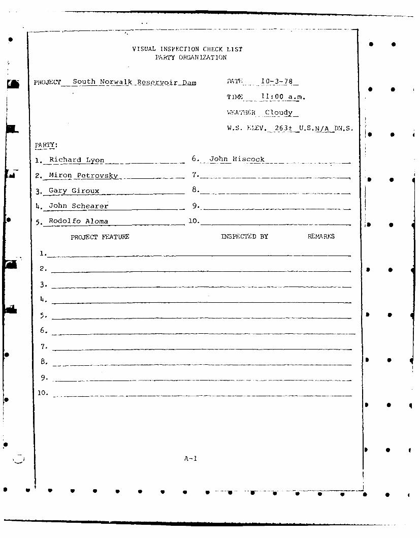
VISUAL INSPECTION CHECK LI STPART ORGAIZAT ION
puj~crSouth Norwalk__Resr-c-)rvo ri-Dam AT; 10-3-78
TD~ 1100 a.mn.
IL W.S. ELlEV. -263±__U.S.A ADR.S.
PA P Ff:
x*Richard ~yn6. John Hi~scock~ ___
2.Miron Petrovsky_ 7. 4 4--------------
3. Gary Giroux 8 ___ __
4. John Schearer 9
5 Rodolfo Aloma 10. ______________
PRojECT FEATURE INSPECTED BY REIMA RKS
2.
3.
4.
7.0
10.__ _ _ _ _ _ _ _ _ _ _ --- _ _ _
* 0 4
00
A-1
*~-- 41i. --
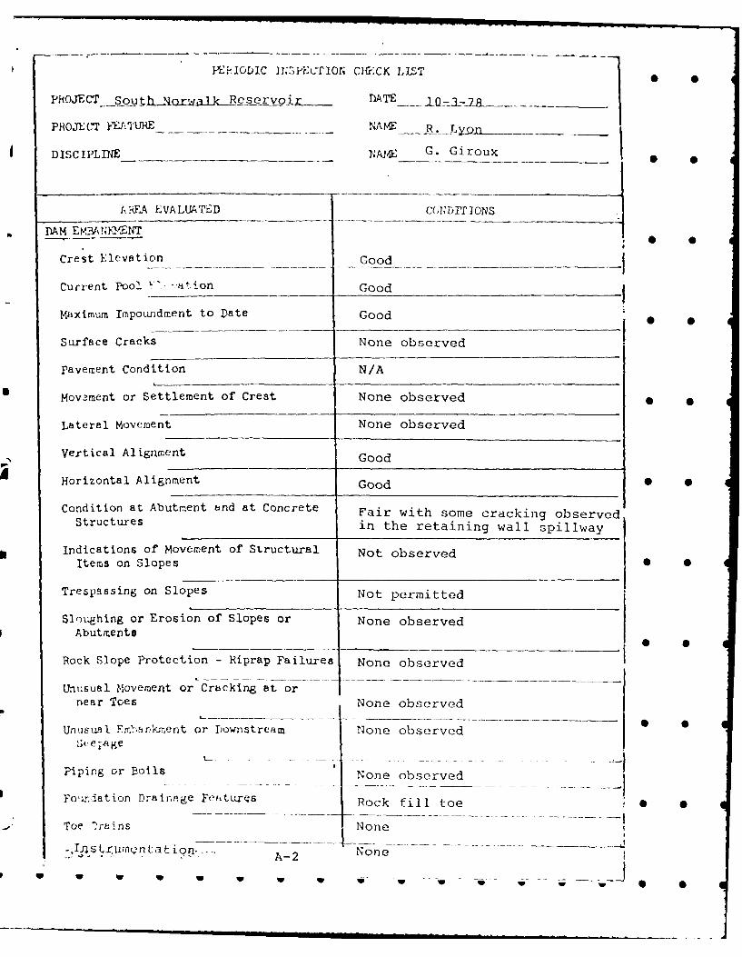
l-.rIoDIC 1J,2PECTION CH CX LILST
PRoJECT_ Sou h jorwjk_2 e s~qrv o DATE_.. IO--7_
PROJEt 'T yJTURE NAM- R. L_____
DISCIPLINE NAE G. Giroux
AREA EVALUATED COjNDITI ONS
DAM EM V31N0YENT
Crest Elevation Good
Current Pool . vt.ion Good
Maximum Impoundment to Date Good 0 0
Surface Cracks None observed
pavement Condition N/A
Movement or Settlement of Crest None observed
Lateral Movement None observed
Vertical Alignment Good
Horizontal Alignment Good • 0
Condition at Abutment and at Concrete Fair with some cracking observedStructures in the retaining wall spillway
Indications of Movement of Structural Not observedItems on Slopes •__
Trespassing on Slopes Not permitted
Sloughing or Erosion of Slopes or None observedAbutments_
Rock Slope Protection - Riprap Failures None observed
Unusual Movement or Crbcking at ornear Toes None observed
Unusual Erftkient or Downstream None observedSee.age
Piping or Boils None observed
Fonnation Drainage Fetures Rock fill toe ,
Toe ?rains None
-. TjU1 .ruirn tation..,., NoneA-2

}%}RIODIC U P c'ICN C*ECK LIST
iROCjTSouth Norwalk Reservoir Dam ___ ATE _..1-3-.
PROJEc-r FEATURE__ -- M. Petrovsky
DISCIPLMIN- IE R. Aloina
AREA EVALUATED COTDIT ION
DIKE EMA >3J
Crest Elevation
Current Pool Elevation North west dike not included in.
Maximum Impoundment to Date____________scope of inspection 0 S
Surface Cracks
pavement Condition
Movement or Settlement of Crest
Lateral Movement
Vertical A]ignment
Horizontal Alignment
Condition at Abutment and at ConcreteStructures
Indications of Movement of StructuralItems on Slopes
Trespassing on Slopes
Sloughing or Erosion of Slopes orAbutments
Bock Slope Protection - Riprap Failure
Unusual Movement or Cracking at ornear Toes
Unusual Fnb1'r=ent or Downstream 0 S
Sceiage
Piping or Boils
Foiundation DraingEe Features
Toc Drains
A-3
S S w * ,

PiE<]ODIC :] qlhCif-,CK ],IS.-T •
pROJECT South Norwalk Reservoir Dam MATE 10-3-78
FFOJEGCT }hATURE J. Schearer
DISC IPLILE -G. Giroux
AREA EVALUIATED COND!'r ION
OUrLET WORKS - INTAKE CHANr L AND
-- ]:'A k SRUCTfURE
a. Approach Charu e
Slope Conditions UNDERWATER
Bottom Conditions
Rock Slides or Falls
Log Boom
Debris
Condition of Concrete Lining
Drains or Weep Holes * S
b. Intake Structure
Condition of Concrete Good sound concrete structure
Stop Logs and Slots
A-4
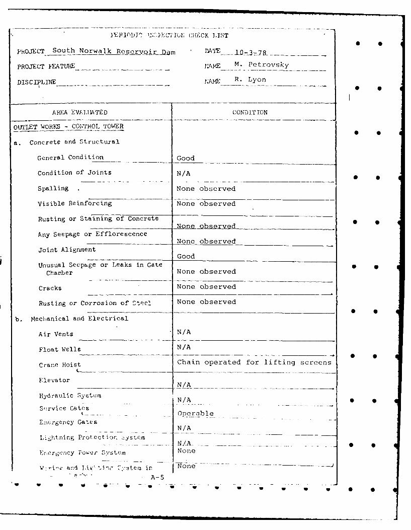
I~L1DJ' ThP:KcI' oi;(:;iiECK LIST
phjOJICT South Norwalk Reservoir .- IOm3-8-
pOE- FEATUR 1AV0E M. Petrovsky
DISCPLIN R. Lyon
AREA EVALUATED COND IT ION
OUI'LET WORKS - CONTROL TOWER
a. Concrete and Structural
General C dton___Good
Condition of Joints N/A
Spalling None observed
Visible Reinforcing None observed
Rusting or Staining of Concrete NoeQsr d
Any Seepage or EfflorescenceNone observed
Joint AlignmentGood
Unusual Seepage or Leaks in GateChamber None observed
Cracks None observed
Rusting or Corrosion of Sttee2. None observed_ _ _ _ _ _ _ _ _ _ _ _ _ _ _ _ _ *
b. Mechanical and Electrical
Air Vents N/A
Float Wells N/A
Crane Hoist Chain operated for lifting screens
ElevatorN/
Hydraulic Systuem N/A
Service Cates-- O ral
£::rer-rency GatesN/A
Litning Protectiorn systcem
Er rtgency Power System None
and bijL' .. inr .% tem ir. Noe - - -
A-5

1iEiODIC L'J:C''5' ION C}riCK LIT S
PiiOJECT South Norwalk Reservoir Dam IT 10-3-78
PROJECT FKATURE _ NA G. Giroux
DISC PLIN T "ME J. Schearer S
APFA EVALUATED CONDITION
OUTLET WORKS - TPAIS ITION AN D CON1JDI -T
General Condition of Concrete
Rust or Staining on Concrete N/A cast iron pipe with valve
Spalling embedded within the body---
Erosion or Cavitation of the dam
Cracking
Alignment of Monoliths Not observed S S
Alignment of Joints Not observed
Niu..bering of Monoliths N/A
*
* 0
A-6
*"T ----IU " - .m - - * .. . . U S S S S S 0 •

POJC*TSouth Norwalk Reservoir Dam ..... 10-3-78
PRO.JECT JILATURE N1JL_ R. Aloma _ _
DISC IPI P 1. Petrovsky
A It~J EVA ILUATED CGW pI' IONOUPLET WOHKM - 3PiIIAYjWEIRJ APPKOAC!
---AND D6Sf&BGE C}L,?,ELS
a. Approach Clannul
General Condition Good
Loort Rock Ovurhar: rv., Channel N/A
Trees Overhanging Channel None
Floor of Approach C, annelGood ___
b. Weir and Training Walls
General Condition oV Concrete Fair to poor
Bust or Staining None
5pallinu Extensive on floor of spillway
Any Vlsiblc Reinforcing channel
Any Seepage or Effloresccict Minor Areas 0
Drain Holesnone
o. Dischhree C:0,aielGeneral Condition Fair 0
Loose Rock Ovurhangijig Channel N/A
Trees Overinanging Channel None observed
Floor of CnelOvrgrown with brush
OLher O)struet irns and gra>'
_ A-7 ... . ..J. . . - -- - m= i Ub | V ! V V i | . . .. . . . .

APPENDIX B
iSe
LIST OF REFERENCES B-1
GENERAL PLAN Plate 1
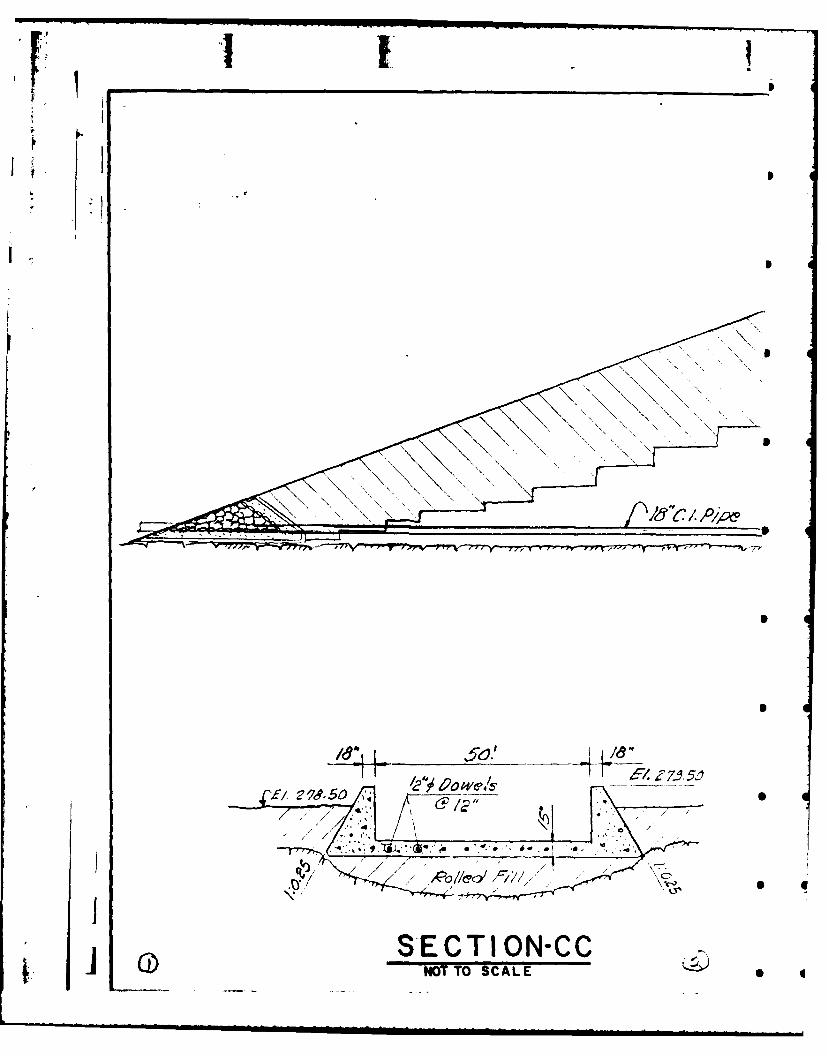
SECTION AND DETAILS Plates 2 & 3
0 0
0 0
0 0
0 0
.0 0 0

* S
LIST OF REFERENCES
1. Norwalk, Connecticut; Second Taxing District; Improvementsto Waterworks System; City Lake Reservoir; Drawings No.459-20 to No. 459-29; February, 1950.
2. Recommended Guidelines for Safety Inspect ion of Dams;Department of the Army; Office of the Chief of Engineer-s;Washington, D.C.; November, 1976.
3. Guide Curves for the Probable Maximum Flood PMF) forRegions of New England based on past Corps of Engineers'Studies; March, 1978.
4. Preliminary Guidance for Estimating Maximum ProbableDischarges in Phase I Dam Safety Investigations; NewEngland Division; Corps of Engineers; March, 1978.
5. Rule of Thumb; Guidance for Estimating Downstream DamFailure Hydrographs; Corps of Engineers; April, 1978. S
6. Instrumentation of Earth and Rockfill Dams; EM 1110-2-1908; Department of the Army; Corps of Engineers;August, 1971.
B-1
U U U U U U U U U U V U U U' U S •

Krc
4- E,11
NOTE: INFORMATION TAKEN FROM
I DRAWINGS SUPPLIED BY THE SECOND0I TAXING DISTRICT NORWALK, CONN.

101 &/179M Ct abe
II
Toe 0'A ~a //s t
~ ~ A
PLANNOT TO SCALE
STORCH ENGINWETHERtSFIELD, CONt
* NATIONAL PROGFSOUTH N(
BELDEN HILL BR
*

- J Ccr n Ct en/,7 - .b
LAN
TO SCALE
.... iPLATE-I
STORCH ENGIN EERS U. S.AR MY ENGI NEE R D. N EWENGLANDCORPS OF ENCRNEERS
WETHERSFIELD, CONNECTICUT WA LyrMAN . MA-el,
NATIONAL PROGRAM OF INSPECTION OF NON -FED. DAMSSOUTH NORWALK RESERVOIR DAM
B .ELDEN HILL. BROOK CONNE-Icu-~SCALE: AS SHOWN
• ! DAT E i NOV. - 1978
I|HI lI

2 // /
* f/ow 2/ l. r.0 4127
Nle w c
S ECTfNOT TO '
el 271/0
6\/ PI//',f /, / 7.
j SECTION-BBS

I I I
I,, -o -- -0 " - --
1- Et 78. 50 A/ew ol/dl Fil
2/
-New enc,Como rgWe// all/,
, / / , / /
2ocA
S ECTION-AANOT TO SCALE
E27/ go
* 1?710
' O// co' FI// / STORCH ENGINE,/" " / """" " / ' ' " ':WETNIASPIELO,--- --- ---
.... ,X"" -. Ex-/$t 6 d 2/e ~NATIONAL PROGRASOUTH NO[
BELDEN HILL SRO.SECTION. -&)

A. e ole l
Pock
[PLATE-STOC ENIER S RYEGIERDV E NLN
,jCORP of-olNec' ri/I
CAT , OV- 9T
1-4741o /C1
S-E TIOIC
NOT T SCAL

4!,i7be, -XwA
SECTION- DDNUT TO SCALE
7 *..IL. /STORCH ENGINE
NATIONAL PROGRi!SOUTH NO
N-CC BELDEN HILL BR(

F- :777 1
OJN- DDSCALE
____ ____ ____ ___P PLATE -3STORCHi ENGIN EERS U.S. ARMY ENGINEER DUVNEW ENGLAND
CORPS OF' ENGINEERS
WETHERSPIELD, CONNECTICUT WALTMAN. MASI
NATIONAL PROGRAM OF INSPECTION OF NON - FED. DAMSSOUTH NORWALK RESERVOIR DAM
BELDEN HILL BROOK ()CONNECTICUTSCALEt AS SHOWN
_____]_DATE :NOV 1I

- -
APPENDIX C
PHOTO LOCATION PLAN Plate 4
PHOTOGRAPHS C-1 to C-4
10 l 9 p lp 9 0 v v ip 0 i

N I T I
.. e.
.# -
TEN ISTRIATORWTAKN FOMN
TAIG ITRC NRAL,,ONCa t rJ~ l~ i

D A
7L7-
/e~t~fOt 0 1 o--------
-; Nell$
V1 -e -/VA
70e o/I oamKD
NTTO SCALE
STQRCH ENGINEERS U.S.ARMYAC
WETHERSFIELD, COmNECTICUT
NATIONAL PROGRAM OF INSPECTIONSOUTH NORWALK RESE
BELDEN HILL BROOK
DENOTES PHOTO LOCATION _______-A____ I I DAT F

10 A
" ti
'NekY hn'kkc ;d i-0
e4
Scree7 CArpb'r .
N i l ,.&/ t/8"'/.,op - "
.T RC EN IN ER U.S ARYEGNE r E NLN
NT N P IooSE,%. LeIOA 8/0' DA/Si [ I
SOUT NOWL REEVI A
elO A'/ASO
I OAT , lv -197
'ALE*
0 NATIONAL PROGRAM OF INSPECTION OF NON-FED. DAMSSOUTH NORWALK RESERVOIR DAM
BELDEN HILL BROOK I -) / CONNECTICUT
OATF N(lV - IT

PHOTO 16 GATE HOUSE FROM ILPSTWIi
PHOJTO 2CFEST OF DAM LOOKING WEST
C-1

IA)
PHOlTO 4
SPILLWAY LOOKING UPWST~tfM
1 C-2
w S

LrA
SF
17)
C-
w w w

I ~ p
n I 0
* 0
-
I.
I S
1 3 0
* S
U
*0
I S S
S S
C-L4
S S S S S U U U U U w w U w S S

APPENDIX Dt0
HYDRAULIC COMPUTATIONS D-1 to D-8
REGIONAL VICINITY MAP Plate 5
DRAINAGE AREA MAP Plate 6
ill •
I S
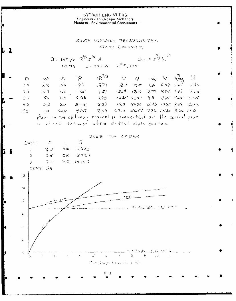
STORCH ENGINLERSEngineers . Landscape Architects
Planners -Environmental Consultants
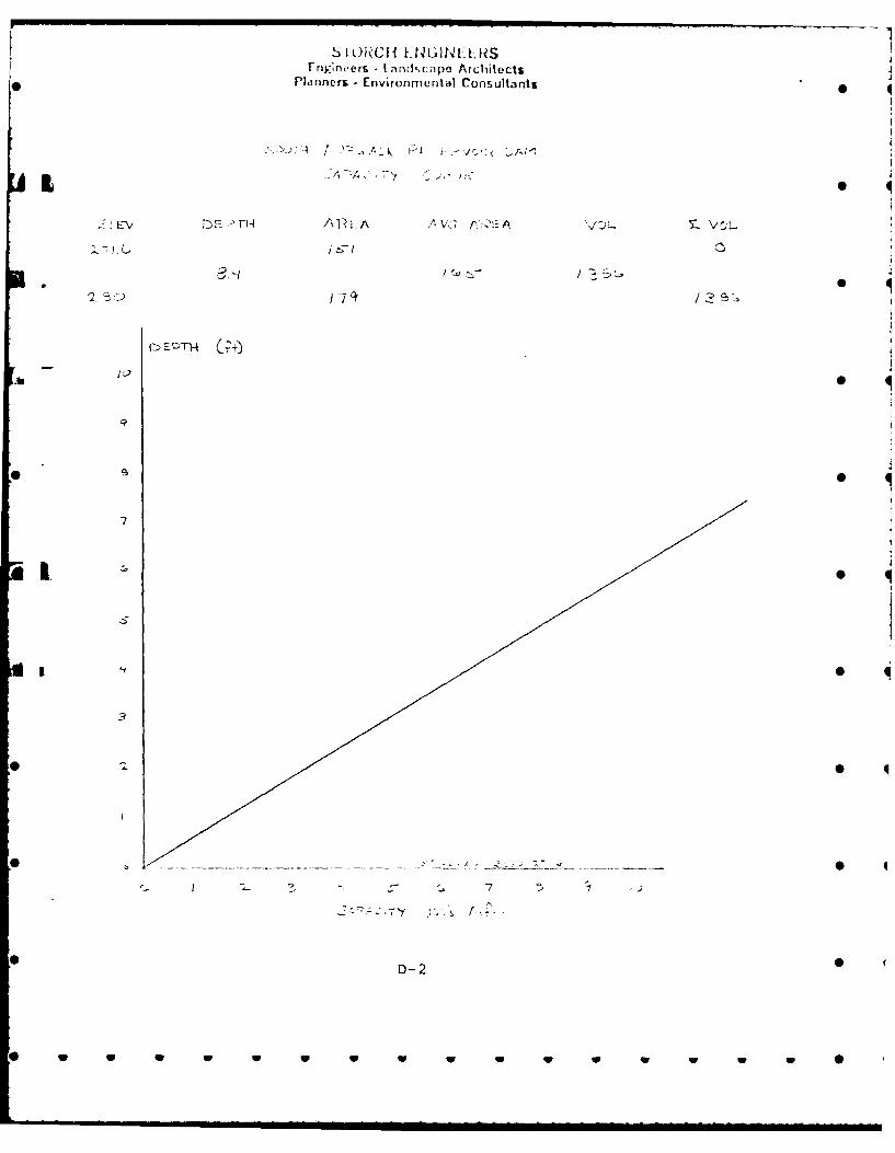
,S':)u TH N D11- ,,A I ,, '-7'_ -- , -- -1 D/'-r I
Q: L-Ki7yr. " '' A Jc- ? 5 \1Q%
~J-c
A P J, 0 4.
-q J .53 2j): 3, - 2.26" /9.18 t' $ 5e3 I.-/ 1,sq zi
?,3 .3. S ,,?i ,7" '.-
e. 6-4 7,, '7.
fro- eitLl : - 4ere Cr; CC-I p;, 9 Q ~r , o,., 4-, o , 0
r. E PTI 1 4f)
II
, ?_ 3 ,7" L 7 5' ,- .
0 4
D-I____ 0
I SIORC~~~I| LN IN :S... . . ..
rng:neers I andccapo ArchitectsPlanners -Environrmental Consultants
-A :A AAV .:.'K 7L. £ vc'
r_ -- r--r V,3
/o/ •
2 j) 1 7~ I
7I
t I I
3
D-2
S Sll U w U U U U w w U U U U
STORCH E[GINEERSEngineers - Land,.cape Architects
Planners - Environmental Consultants
I,
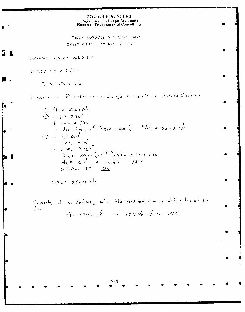
SQp,: 5-00cOr
I ITO _ .0
I,
- -t-oFO 0 7 L7
0 C0j 0pt
D-3
. . . . . .. . ....UU U , U, U . . . . . . . .

S I OFRCH ENGINLERSEniincers - Lndfscape Architects
Planners - Environmental Consultants
2 7 '3
7 .5
* -- ~ ~~~~ P-~ H -s .//. z3;
IC.!D-4

SIORCH ENGINEERSEngineers landscapo Architects
Planners Environmental Consultants
i •
D-5
' a, a -a 0 0 0 0 V w w w - I ,0
9 0
*-5
D A 1?
17!
_!
Io,9 ' 3 2~]JY:2
,- - ]
S

S'i ORCH FIN(INLLHSEnjineers -Ln+.capo Architects
Planners • Environmental Consultants S
/7
40.
-D-6
- 7 - ' .& i I
<>. " ; > 4 ' .
7, "-"2 ' 2c -. s .- ,"i' ":, .3 .-- I a ,/ '. .'- . -' :. ::'..', * L . .: 2 ,,", ,7a
,*, - _/o - ,o )2 5 " ' 7J 7 .- ,7 .C.)
* S
D-6
p

S1ORCH ENGINLERSEngineers . Lindscape Architects
Planners - Environmental Consultants
,* '. a-_-c ,,- - W ,1 . .- O* ::3 , -- . - 'J Th- ' r~-. ,' " . . .
l •-
V : > l /°-
-. i2-" "j L ' - i.& /-LIj'J j : £L-ilVi 0-- 5
- . /
. . - -" ,- h= I- T' :-' - -
\L , %f,
I., .I "-K'- aT , •- / . - . "
I 3 (6Q -. /- ,
2 " - ='-7 3 - = -- ,. '
\ <, a -Q7
wT
D-77
SI ORCIH ENGIN-ERSEngineers -Landscape Architects
Planners - Environmental Consultants
/ . J - ----
-D -8
/-. w -
- - ,'.,
I 0
I 0
D-8 * t
S U U V S V S V V V V V U 5 6

4 ~ .r
* -
lb--
lu-zic't-
41 ---
.-
~' \ ~lo
LEGEND
DE OE IIS
FFO DN
IN CAE OFDAM FILUR

ST, R -L G I
BEDE r.LA UR O*

S7
'41.
-21 ~ ~ *
~0
Z, '
JLt
r * ~ I N( - /t*
&/7 . -~ 7-
.- . I , . , 1 . ,-
-SAL AS SHW
NOV197

S S
R 0
1<
I \'~p~ C~sto I 'n) l
/ -. \ ( ~ vt
V ~ V
-H~ C K L. L-A~~N ' /'
'~T'
SCAL
0 U(0
U.S.ARMY,CORPSOFENGINEERS 73,
NEW lENGLAND DIVISIONWALTHAM, MASS. DRAINAGE AREA MAP
w w w w w I w w v w w w w w

0 •
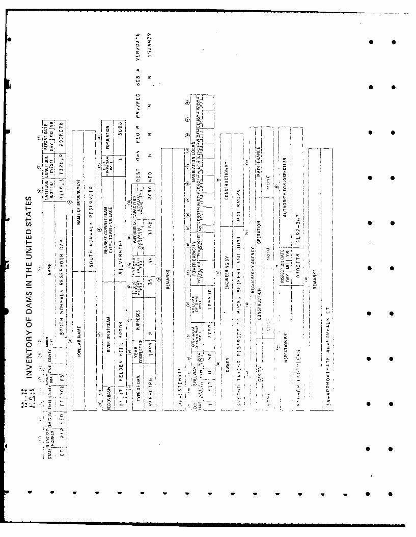
APPENDIX E
INFORMATION AS CONTAINED IN THE NATIONALINVENTORY OF DAMS
- w
3 5
0! •
0 u U
-i~
t4
U, z
Z* 0
L..o'.-
P7. __D
-- U ~2t
*t
-~-10
C - c .., I
~Tz ~ I cc
z~
Lrr
-weI
I; -tf
z
IW
Sx
47 1~~lit
:Z
Ow"
Sl
S iC4