
ncr5877
74
5877 Personas ATM Site Preparation 1468 mm (57.8 in.) 1490 mm (58.66 in.) 715 mm (28.15 in.) 472 mm (18.58 in.) 1335 mm (52.56 in.) 272.5mm (10.7in.) 16mm (0.6in.) 5mm (0.2in.) 37.5mm (1.5in.) 16mm (0.6in.) 5mm (0.2in.) Front of Terminal Rear of Terminal 426mm (16.8in.) 120mm (4.7in.) Publication ID: B006-6208-A000 Date: 1101
-
Upload
esteban-daniel-perez -
Category
Documents
-
view
236 -
download
3
Transcript of ncr5877

5877 Personas ATM
Site Preparation
1468 mm(57.8 in.)
1490 mm(58.66 in.)
715 mm(28.15 in.)
472 mm(18.58 in.)
1335 mm(52.56 in.)
272.5mm
(10.7in.)
16mm
(0.6in.)
5mm
(0.2in.)
37.5mm
(1.5in.)
16mm
(0.6in.) 5mm
(0.2in.)
Front of Terminal
Rear of Terminal
426mm
(16.8in.)
120mm
(4.7in.)
Publication ID: B006-6208-A000
Date: 1101
Book.bk Page 1 Tuesday, November 6, 2001 2:04 PM

NOTICE
This is a contractual document. It contains important warning and confers important legal rights and obligations. You are advised to read it carefully.
It is the responsibility of the customer to assure that all installation preparations are complete and in compliance with all specifications and requirements of NCR and all applicable national, state, or local codes, regulations and laws.
The product described in this book is a licensed product of NCR Corporation.
Trademark Information
It is the policy of NCR Corporation (NCR) to improve products as new technology, components, software, and firmware become available. NCR, therefore, reserves the right to change specifications without prior notice.
All features, functions, and operations described herein may not be marketed by NCR in all parts of the world. In some instances, photographs are of equipment prototypes. Therefore, before using this document, consult with your NCR representative or NCR office for information that is applicable and current.
To maintain the quality of our publications, we need your comments on the accuracy, clarity, organization, and value of this book.
Address correspondence to:
NCR Financial Solutions Group LtdInformation SolutionsKingsway WestDundee, ScotlandDD2 3XX
© 2001By NCR CorporationDayton, Ohio U.S.A.All Rights Reserved
Book.bk Page 2 Tuesday, November 6, 2001 2:04 PM

Book.bk Page iii Tuesday, November 6, 2001 2:04 PM
P77 ATM - Site Preparation
iiiFederal Communications Commission (FCC) Radio Frequency Interference Statement
Note: This equipment has been tested and found to comply with the limits for a Class A digital device, pursuant to Part 15 of the FCC Rules. These limits are designed to provide reasonable protection against harmful interference when the equipment is operated in a commercial environment. This equipment generates, uses, and can radiate radio frequency energy and, if not installed and used in accordance with the instruction manual, may cause harmful interference to radio communications. Operation of this equipment in a residential area is likely to cause harmful interference in which case the user will be required to correct the interference at his own expense.
Canadian Class A Device Declaration
This digital apparatus does not exceed the Class A limits for radio noise emissions from digital apparatus set out in the Radio Interference Regulations of the Canadian Department of Communications.
Le présent appareil numérique n’émet pas de bruits radioélectriques dépassant les limites applicables aux appareils numériques de la classe A prescrites dans le Réglement sur le brouillage radioélectrique édicté par le ministère des Communications du Canada.
Book.bk Page iv Tuesday, November 6, 2001 2:04 PM
Information to UserThis equipment must be installed and used in strict accordance with the manufacturer’s instructions. However, there is no guarantee that interference to radio communications will not occur in a particular commercial installation. If this equipment does cause interference, which can be determined by turning the equipment off and on, the user is encouraged to consult an NCR service representative immediately.
Caution NCR Corporation is not responsible for any radio or television interference caused by unauthorised modifications of this equipment or the substitution or attachment of connecting cables and equipment other than those specified by NCR. Such unauthorized modifications, substitutions, or attachments may void the user’s authority to operate the equipment. The correction of interference caused by such unauthorized modifications, substitutions, or attachments will be the responsibility of the user.
iv P77 ATM - Site Preparation
Book.bk Page v Tuesday, November 6, 2001 2:04 PM
P77 ATM - Site Preparation
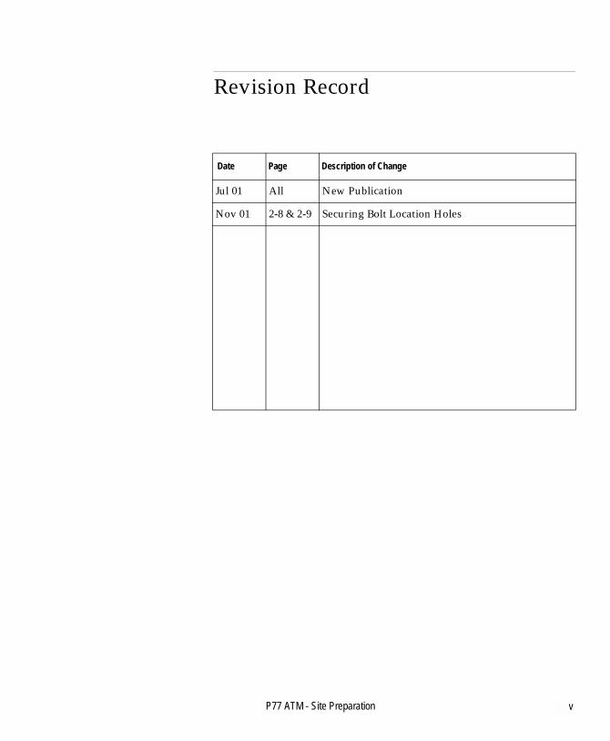
vRevision Record
Date Page Description of Change
Jul 01 All New Publication
Nov 01 2-8 & 2-9 Securing Bolt Location Holes

Book.bk Page vi Tuesday, November 6, 2001 2:04 PM
vi P77 ATM - Site Preparation
Book.bk Page vii Tuesday, November 6, 2001 2:04 PM
P77 ATM - Site Preparation
viiPrefaceAbout This Document
Preface
This book contains the information necessary for the preparation of a site conforming to NCR specifications. It is very important that the site complies with the requirements specified in this document because, once the equipment has been installed, deficiencies in site preparation or the problems caused by these deficiencies are much more difficult to detect and correct. Further, failure to comply with these requirements or to take proper steps to protect equipment against risks identified in this document may cause serious damage to the equipment and to the customer’s business.
In addition to the need to comply with the requirements specified, electrical wiring and mechanical systems must also comply with all relevant codes, laws and regulations.
It is important that the site be prepared by a customer or his agent who is fully conversant with the special requirements of electronic equipment. The responsibility for ensuring that the site is prepared in compliance with this document remains with the customer.
For information and guidance only, a list is provided, in general terms, of those matters for which the customer is responsible. This list is not intended to be comprehensive, and in no way modifies, alters, or limits the responsibility of the customer for all aspects of adequate site preparation.
NCR staff will be available to answer questions relating to the contents of this document but, except where
● the customer has been notified that a full or partial consultancy service is available and/or that NCR will be willing to undertake a preliminary or final site survey and the customer shall have entered into a formal contract with NCR for provision of the same

About This DocumentPreface
Book.bk Page viii Tuesday, November 6, 2001 2:04 PM
● no comment, suggestion or advice offered or not offered about preparation of the site nor any inspection of the site whether before or after preparation is to be taken as approval of the location of the site and equipment or of its preparation and NCR will not be liable in respect of any comment, suggestion or advice given by its staff or in respect of any failure to give advice.
Finally, only the customer can know the full extent of damage which may be caused to his business by reason of failure of the equipment which is to be installed. For this reason, it is the customer’s responsibility to ascertain the extent of any such possible damage to his existing or planned business, and to effect full insurance in respect of it.
viii P77 ATM - Site Preparation

Contents
Table of Contents
ix
Book.bk Page ix Tuesday, November 6, 2001 2:04 PM
P77 ATM - Site Preparation
About This Document
Preface ......................................................................................................vii
Chapter 1Planning Check List and Installation Accessories
Planning Check List ..............................................................................1-1Installation Accessories ........................................................................1-2
Chapter 2Physical Requirements
Overview ................................................................................................2-1Customer Responsibilities....................................................................2-2Product Identification ...........................................................................2-3Packaging Dimensions .........................................................................2-4Terminal Dimensions............................................................................2-5Installation And Service Clearances ...................................................2-6
Securing Bolt Location Points .........................................................2-8Securing Bolts....................................................................................2-9Floor Covering ..................................................................................2-9P77 Location ......................................................................................2-9Weight and Floor Loading ............................................................2-10
Access For All ......................................................................................2-11Heights To Main Facia Items ........................................................2-12Recommended Wheelchair Clearance.........................................2-13

Table of Contents
Book.bk Page x Tuesday, November 6, 2001 2:04 PM
Chapter 3Electrical Requirements
Power Quality Distribution And Grounding Requirements.......... 3-1AC Requirements ............................................................................. 3-1Input Voltage Setting....................................................................... 3-1Power Cable ...................................................................................... 3-2Grounding Requirements ............................................................... 3-3Transient Power Loss ...................................................................... 3-3EMI Susceptibility ............................................................................ 3-3EMI Emission.................................................................................... 3-3
Communications Requirements ......................................................... 3-4High Order Communications Cables............................................ 3-4Alarm Interface Cable...................................................................... 3-6
Chapter 4Installation Site Environmental Requirements
Environmental Requirements ............................................................. 4-1Temperature And Humidity .......................................................... 4-1All Environments ............................................................................. 4-2Barometric Pressure ......................................................................... 4-2Heat Dissipation............................................................................... 4-2Air Flow............................................................................................. 4-2Temperature Rise ............................................................................. 4-2Acoustical Noise............................................................................... 4-2
Chapter 5Decals
Decal Specifications .............................................................................. 5-1Card Accept....................................................................................... 5-2Card Orientation Decal ................................................................... 5-3Exit/Entry Slot Decals ..................................................................... 5-4
x P77 ATM - Site Preparation

Table of Contents
Book.bk Page xi Tuesday, November 6, 2001 2:04 PM
Appendix ATransient Protection
AC Power Line Transient Protection.................................................A-1Data Line Transient Protection...........................................................A-3
Appendix BPower Protection
NCR Power Protection and Cabling Products ................................. B-1AC Power Line Transient Protection............................................ B-1Data Line Transient Protection...................................................... B-2Uninterruptible Power Supplies ................................................... B-2Contact Information ........................................................................ B-4
IndexIndex ...............................................................................................Index-1
User Feedback Form
P77 ATM - Site Preparation xi

Table of Contents
Book.bk Page xii Tuesday, November 6, 2001 2:04 PM
xii P77 ATM - Site Preparation

Table of ContentsPlanning Check List and Installation Accessories
Book.bk Page xiii Tuesday, November 6, 2001 2:04 PM
P77 ATM - Site Preparation
Chapter 1
Planning Check List and Installation Accessories
Planning Check List 1-1
Installation Accessories 1-2

Table of ContentsPlanning Check List and Installation Accessories
Book.bk Page xiv Tuesday, November 6, 2001 2:04 PM
P77 ATM - Site Preparation

Book.bk Page 1 Tuesday, November 6, 2001 2:04 PM
P77 ATM - Site Preparation
-11Planning Check ListPlanning Check List and Installation AccessoriesA
Planning Check List 1
To assist in preparing your site for the arrival of the terminal, it is recommended that the various procedures, detailed in the following check list be carried out prior to the arrival of the terminal. The procedures given are listed in chronological order, starting with the procedure that should be carried out first.
Activity
Select site and make scaled floor plan
Ensure correct environmental conditions
Establish all contractor and vendor related schedules including surrounds/kiosk vendors
Check communication line requirements
Plan application development
Check floor plan and make any alterations
Install additional electrical outlets (if required)
Prepare site for data communication
Arrange for designing and printing of overlays/decals
Order information products
Order media supplies
Plan operator training (optional)
Ensure data communications equipment is installed and tested
Ensure installation accessories listed are available

Planning Check List and Installation AccessoriesInstallation Accessories
Book.bk Page 2 Tuesday, November 6, 2001 2:04 PM
Installation Accessories 1
When installing the terminal, it is recommended that the following items are available:
● Pincers/claw hammer to remove staples/nails from around the air/sea pallet
● 19mm (3/4 in.) for UL safe, ring/open-ended combination spanner and socket to remove pallet bolts, and to fit floor bolts
● Cross-head screwdriver● 13mm (17/32 in.) spanner or socket - to remove the four screws
that secure either of the cross struts to the pallet● 10mm (13/32in.) ring/open ended combination spanner - for
attaching earth stud● 17 mm (11/16 in.) ring/open-ended combination spanner or
socket● Wooden/metal safety blocks to support the terminal during
installation● 4mm (7/64 in.) Allen key● Hex nut driver set (including M3 and M4 sizes)● Selection of screwdrivers for flat blade and cross head
applications● Forklift or a lifting/moving device● Packing to protect exterior of the terminal while on trolleys● Lifting Trolleys (may need to be modified, refer to the NCR
5877 Personas ATM Installation Manual (B006-6209-A000)● Scissors.
1-2 P77 ATM - Site Preparation

Table of ContentsPhysical Requirements
Book.bk Page iii Tuesday, November 6, 2001 2:04 PM
P77 ATM - Site Preparation
Chapter 2
Physical Requirements
Overview 2-1
Customer Responsibilities 2-2
Product Identification 2-3
Packaging Dimensions 2-4
Terminal Dimensions 2-5
Installation And Service Clearances 2-6Securing Bolt Location Points 2-8Securing Bolts 2-9
UL Standard Security Safe 2-9Floor Covering 2-9P77 Location 2-9Weight and Floor Loading 2-10
Standard Security (UL 291) Safe 2-10
Access For All 2-11Heights To Main Facia Items 2-12Recommended Wheelchair Clearance 2-13

Table of ContentsPhysical Requirements
Book.bk Page iv Tuesday, November 6, 2001 2:04 PM
P77 ATM - Site Preparation

Book.bk Page 1 Tuesday, November 6, 2001 2:04 PM
P77 ATM - Site Preparation
-12OverviewPhysical RequirementsB
Overview 2
The NCR 5877 Personas ATM (P77) is a self-service ATM which may be installed in any suitable interior location.
The P77 is designed to enable customers to avail themselves of a range of services such as:
● Cash Withdrawals● Receipt Printing● Cheque Book Requests● Account Enquiries.
Physical RequirementsCustomer Responsibilities
Book.bk Page 2 Tuesday, November 6, 2001 2:04 PM
Customer Responsibilities 2
The customer must do or provide the following:
● When required by NCR, provide the NCR customer service representative with appropriate drawings that indicate:● Location of the equipment● Site wiring (power and signal, paths and lengths)● Location of other equipment capable of generating electrical
noise, electromagnetic interference, heat, etc.● Make building alterations necessary to meet wiring and other
site requirements● Provide and install all communications cables, wall jacks,
special connectors and associated hardware● Provide and install necessary power distribution boxes,
conduits, grounds, lightning protection and associated hardware
● Make sure all applicable codes, regulations and laws (including but not limited to electrical, building, safety and health, disabilities) are met
● Provide and install auxiliary power or other equipment as required
● Provide storage or service areas as required● Make sure the environmental requirements of the system/unit
are met● Provide floor coverings and environmental systems that limit or
control static electricity build-up and discharge.
2-2 P77 ATM - Site Preparation

Physical RequirementsProduct Identification
Book.bk Page 3 Tuesday, November 6, 2001 2:04 PM
Product Identification 2
The product is identified by a class type number (5877), and a 4-digit model number which is printed on a label (similar to the following) attached to the inside wall of the P77 near the ON/OFF switch. The first two digits of this model number identify the major model (normally 01), the next two digits identify the minor model (normally 01). The serial number is unique to each P77, as is the Class number combined with the Tracer number.
Class
Serial
Tracer
Vac.
5877
08-XXXXXXXX
08-XXXXX
120/220
Model
Hz. 50/60
XXXX
A.10.0
This device complies with Part 15 of the FCC Rules. Operation is subject to the following two conditions:Electromagnetic Compatibility
This apparatus does not exceed Class A limits for radio noise emissions set out in the Radio Interference
Le present appariel n’emet pas bruits radioelectriques depassant les limites de la classe A prescrites
“Complies with FDA Radiation Performance Standards, 21 CFR Subchapter J”.
NCR Financial Solutions Group Ltd
Made in U.K.
(1) This device may not cause harmful interference, and (2) this device must accept any interference
DundeeScotland
received, including interference that may cause undesired operation.
Regulations of Canada.
dans le Reglement sur le brouillage radioelectrique du Canada.
P77 ATM - Site Preparation 2-3

Physical RequirementsPackaging Dimensions
Book.bk Page 4 Tuesday, November 6, 2001 2:04 PM
Packaging Dimensions 2
The type of packaging used is dependent on the shipping method - road or air/sea freight. If access to the installation location is not wide enough to allow the package to pass through, unpack the P77 in an area with sufficient access.
Air/Sea Package: 2
● Height = 1750mm (68.90 in.)● Depth = 1150mm (45.28 in.)● Width = 800mm (31.49 in.)
Road Package: 2
● Height = 1640mm (64.56 in.)● Depth = 1200mm (47.24 in.)● Width = 800mm (31.49 in.).
Air and Sea Road
1750 mm
(68.90 in.)
800 mm
(31.50 in.)
1150 mm
(45.28 in.)
1200 mm
(47.24 in.)
800 mm
(31.50 in.)
1640 mm
(64.57 in.)
2-4 P77 ATM - Site Preparation

Physical RequirementsTerminal Dimensions
Book.bk Page 5 Tuesday, November 6, 2001 2:04 PM
Terminal Dimensions 2
1468 mm
(57.8 in.)1490 mm
(58.66 in.)
715 mm
(28.15 in.)472 mm
(18.58 in.)
1335 mm
(52.56 in.)
P77 ATM - Site Preparation 2-5

Physical RequirementsInstallation And Service Clearances
Book.bk Page 6 Tuesday, November 6, 2001 2:04 PM
Installation And Service Clearances 2
The following illustrations show both minimum and recommended floor areas required for installing, servicing and replenishing a P77.
Note: This illustrations show the safe door in the service position.
Minimum
38 mm
(1.5 in.)
38 mm
(1.5 in.)
753 mm
(29.7 in.)
930 mm
(36.6 in.)
908 mm
(35.8 in.)
548 mm
(21.6 in.)360 mm
(14.2 in.)
Cable Accesson Rear Panel
2-6 P77 ATM - Site Preparation

Physical RequirementsInstallation And Service Clearances
Book.bk Page 7 Tuesday, November 6, 2001 2:04 PM
Recommended
38 mm
(1.5 in.)
38 mm
(1.5 in.)
753 mm
(29.7 in.)
1213 mm
(47.8 in.)
1492 mm
(58.7 in.)
548 mm
(21.6 in.)472 mm
(18.6 in.)
Cable Accesson Rear Panel
P77 ATM - Site Preparation 2-7
Physical RequirementsInstallation And Service Clearances
Book.bk Page 8 Tuesday, November 6, 2001 2:04 PM
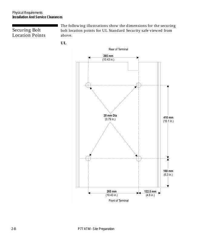
Securing Bolt Location Points 2
The following illustrations show the dimensions for the securing bolt location points for UL Standard Security safe viewed from above.
UL
122.5 mm
(4.8 in.)265 mm
(10.43 in.)
160 mm
(6.3 in.)
410 mm
(16.1 in.)
20 mm Dia
(0.79 in.)
265 mm
(10.43 in.)
Rear of Terminal
Front of Terminal
2-8 P77 ATM - Site Preparation

Physical RequirementsInstallation And Service Clearances
Book.bk Page 9 Tuesday, November 6, 2001 2:04 PM
Securing Bolts 2
The P77 must be bolted to the floor using four (4) securing bolts. The floor must be capable of taking the anchor points for the bolts.
Note: The securing bolts, anchors and appropriate washers must be supplied by the owning organisation.
The minimum specification for bolts to secure the P77 to a plinth or a stone/concrete floor is:
UL Standard Security Safe 2
● M12 Rawlbolt - 12mm (0.47 in.) diameter x 38mm (1.5 in.) minimum long
● Anchor point for M12 Rawlbolt, length suitable to clamp 25.4mm (1 in.) minimum of bolt.
Floor Covering 2
An antistatic floor covering should be used. This floor covering should be of a type which will not generate dust or fluff.
P77 Location 2
The P77 should not be located in a position where bright sunlight will fall directly on the P77 screen.
Tighten only to
compress
Spring Washer
Rawlbolt
Ground
Safe
Anchor Washer
P77 ATM - Site Preparation 2-9

Physical RequirementsInstallation And Service Clearances
Book.bk Page 10 Tuesday, November 6, 2001 2:04 PM
Weight and Floor Loading 2
The P77 must be installed on a solid, level floor capable of supporting the maximum weight. The weight of the P77 varies with configuration, however, only the maximum weight should be considered since additional options may be added after installation. The P77 can be stabilised by using the bolts that secure the transportation feet to the terminal. Refer NCR 5877 Personas ATM Installation Manual (B006-6209-A000).
Note: Floor loading is calculated by dividing the maximum weight of the P77 by the surface area of the P77 base (the area in contact with the floor).
Standard Security (UL 291) Safe 2
● Maximum weight: 535kg (11791lb.)● Floor loading: 1585kg/m2 (325lb/ft2).
2-10 P77 ATM - Site Preparation

Physical RequirementsAccess For All
Book.bk Page 11 Tuesday, November 6, 2001 2:04 PM
Access For All 2
The P77 is designed to meet optimum height and reach requirements to provide comfortable access for all users. This design takes account of wheelchair users, the visually impaired and all others. For wheelchair users, optimized parallel approach is offered, providing security and private space if installed according to recommendations.
The P77 complies with the height and reach requirements of the Canadian Standards Association (CSA) Barrier Free Access and the Americans with Disabilities Act (ADA).
P77 ATM - Site Preparation 2-11

Physical RequirementsAccess For All
Book.bk Page 12 Tuesday, November 6, 2001 2:04 PM
Heights To Main Facia Items 2
The following illustrations shows the heights from the P77 base (safe floor) to the main items, or exit slots, located on the P77 facia.
11
37
mm
(44.
8in
.)of
Top
FD
KK
ey
11
22
mm
(44.
2in
.)of
CR
T(C
RT
Ang
le70
� )
93
2m
m(3
6.7
in.)
of5
Key
(Key
boar
dA
ngle
15� )
82
2m
m(3
2.4
in.)
ofC
urre
ncy
Exi
t
10
47
41
.2m
m(
in.)
ofC
ard
Ent
ry
11
52
mm
(in
.)of
Rec
eipt
Exi
t4
5.4
2-12 P77 ATM - Site Preparation

Physical RequirementsAccess For All
Book.bk Page 13 Tuesday, November 6, 2001 2:04 PM
Recommended Wheelchair Clearance 2
The following illustration shows the recommended clearance for wheelchair approach.
Wheelchair TurningCircle O 1500mm
1500 mm
(59.1 in.)
1500 mm
(59.1 in.)
cL
750 mm
(29.5 in.)750 mm
(29.5 in.)
P77 ATM - Site Preparation 2-13

Physical RequirementsAccess For All
Book.bk Page 14 Tuesday, November 6, 2001 2:04 PM
2-14 P77 ATM - Site Preparation

Table of ContentsElectrical Requirements
Book.bk Page xv Tuesday, November 6, 2001 2:04 PM
P77 ATM - Site Preparation
Chapter 3
Electrical Requirements
Power Quality Distribution And Grounding Requirements 3-1AC Requirements 3-1Input Voltage Setting 3-1Power Cable 3-2Grounding Requirements 3-3Transient Power Loss 3-3EMI Susceptibility 3-3EMI Emission 3-3
Communications Requirements 3-4High Order Communications Cables 3-4
High Order Communications Standard Cable (RS-232) 3-4Alarm Interface Cable 3-6

Table of ContentsElectrical Requirements
Book.bk Page xvi Tuesday, November 6, 2001 2:04 PM
P77 ATM - Site Preparation

Book.bk Page 1 Tuesday, November 6, 2001 2:04 PM
P77 ATM - Site Preparation
-13Power Quality Distribution And Grounding RequirementsElectrical RequirementsC
Power Quality Distribution And Grounding Requirements 3
Voltage transients, line noise, surges, sags, impulses, and spikes may be experienced routinely or sporadically. When such phenomena occur, the use of protective devices, as described in Appendix A and B, may be required to ensure proper operation of the equipment.
AC Requirements 3
The maximum current requirements at various input voltages are:
● 8.2A at 120V● 4.1A at 240V.
The maximum inrush current requirements at various input voltages are:
● 200A peak at 136V● 150A peak at 257V.
Input Voltage Setting 3
The P77 can operate from the following input mains voltages:
● 104V to 136V at 50/60Hz● 198V to 257V at 50/60Hz.

Electrical RequirementsPower Quality Distribution And Grounding Requirements
Book.bk Page 2 Tuesday, November 6, 2001 2:04 PM
Power Cable 3
The power cable supplied with the P77 is fitted with a NEMA type 5-15P power source connector. If this is not suitable for your use, it should be replaced with a suitable power source connector. This connector must be wired as shown below:
The power cable supplied is 3m (9ft 9 in.) in length. If it is necessary to increase this length to meet site requirements, then the extension must satisfy local or country regulations.
Warning This equipment must be earthed.
.
Note: The annotations within brackets are included to comply with United Kingdom legislation and refer to the markings on United Kingdom three pin plugs.
3-2 P77 ATM - Site Preparation

Electrical RequirementsPower Quality Distribution And Grounding Requirements
Book.bk Page 3 Tuesday, November 6, 2001 2:04 PM
Grounding Requirements 3
The P77 operates from a single phase 3 wire supply; live, neutral and ground. The power requirements of this unit will normally permit it to operate within existing wiring configurations and from existing branch mains outlets with the following provisions:
1 If this supply is provided from a general purpose distribution panel, the other branch circuits from this panel must not be used to support heavy inductive loads such as air conditioners, elevators, microwave ovens, and so on. Nor may such equipment be operated on the same branch circuit as the P77.
2 If using distribution panels, all branch circuit grounding conductors must be connected to an insulated terminal strip in the distribution panel. The grounding conductor from the distribution panel to the building ground point must be at least equal in size to the power conductor necessary to supply the NCR system.
Note: The building ground point can affect data integrity. For additional information refer to the ‘Data Line Transient Protection’ section of Appendix A.
Transient Power Loss 3
The voltage loss due to power interruptions must not be more than 50% of the nominal value for a maximum of one half cycle at a maximum rate of 1 every 10 seconds.
EMI Susceptibility 3
The P77 meets NCR CES-2-11-09 and CES-2-11-10 (details available on request).
EMI Emission 3
The P77 meets FCC Class A and FTZ VDE 0871/0875 requirements for radiated and conducted emission.
P77 ATM - Site Preparation 3-3

Electrical RequirementsCommunications Requirements
Book.bk Page 4 Tuesday, November 6, 2001 2:04 PM
Communications Requirements 3
Voltage transients, line noise, surges, sags, impulses, and spikes may be experienced routinely or sporadically. When such phenomena occur, the use of protective devices, as described in Appendix A, may be required to ensure proper operation of the equipment.
It is the responsibility of the customer to assure that all installation preparations are complete and in compliance with NCR specifications and requirements and with all national, state or local telephone and telegraph regulations and laws.
High Order Communications Cables 3
The high order communications cable type depends upon the communications system to be used.
Note: Communications cables are not supplied with the P77. If these cables are required, it is the customer’s responsibility to have them installed.
All communications cables are routed through the back of the P77, underneath the module tray to the PC core.
High Order Communications Standard Cable (RS-232) 3
The standard high order communications system supports most common bit and byte orientated disciplines (synchronous and asynchronous) with an RS-232 interface.
3-4 P77 ATM - Site Preparation
Electrical RequirementsCommunications Requirements
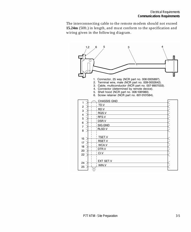
Book.bk Page 5 Tuesday, November 6, 2001 2:04 PM
The interconnecting cable to the remote modem should not exceed 15.24m (50ft.) in length, and must conform to the specification and wiring given in the following diagram.
P77 ATM - Site Preparation 3-5

Electrical RequirementsCommunications Requirements
Book.bk Page 6 Tuesday, November 6, 2001 2:04 PM
Cable Preparation 3At a point 940mm (37 in.) from the connector end of the cable, remove a 20mm (0.8 in.) section of the outer sleeve as shown.
Note: Take care not to cut through the cable shielding when removing the outer sleeve.
Alarm Interface Cable 3
The P77 may, optionally, be configured to provide an alarm interface which enables the P77 to be connected to an external local alarm system. The interface may take the form of one of two options; a basic alarm system or an enhanced alarm system.
The external alarm system must provide to the P77, through the alarm interface cable wiring, a non-interruptible, stabilized power supply with the following specifications:
● 12V + 2V dc● 200mA maximum● Ripple, 5% maximum.
20mm(0.8in.)
940 mm(37.0 in.)
3-6 P77 ATM - Site Preparation

Electrical RequirementsCommunications Requirements
Book.bk Page 7 Tuesday, November 6, 2001 2:04 PM
The interconnecting cable to the P77 is similar for both alarm interface options and must conform to the following specification and wiring:
P77 ATM - Site Preparation 3-7

Electrical RequirementsCommunications Requirements
Book.bk Page 8 Tuesday, November 6, 2001 2:04 PM
Alarm Interface Cable Wiring 3
3-8 P77 ATM - Site Preparation

Electrical RequirementsCommunications Requirements
Book.bk Page 9 Tuesday, November 6, 2001 2:04 PM
Cable Preparation 3Starting from the connector end, remove 20mm (0.8 in.) sections of the outer sleeve at the distances detailed in the following diagram.
Note: Take care not to cut through the cable shielding when removing the outer sleeve.
20 mm(0.8 in.)
20 mm(0.8 in.)
20 mm(0.8 in.)
400 mm(15.7 in.)
330 mm(13.0 in.)290 mm
(11.4 in.)
P77 ATM - Site Preparation 3-9

Electrical RequirementsCommunications Requirements
Book.bk Page 10 Tuesday, November 6, 2001 2:04 PM
3-10 P77 ATM - Site Preparation

Table of ContentsInstallation Site Environmental Requirements
Book.bk Page xi Tuesday, November 6, 2001 2:04 PM
P77 ATM - Site Preparation
Chapter 4
Installation Site Environmental Requirements
Environmental Requirements 4-1Temperature And Humidity 4-1
Normal Operating Range (Interior ATM Environment) 4-1All Environments 4-2Barometric Pressure 4-2Heat Dissipation 4-2Air Flow 4-2Temperature Rise 4-2Acoustical Noise 4-2

Table of ContentsInstallation Site Environmental Requirements
Book.bk Page xii Tuesday, November 6, 2001 2:04 PM
P77 ATM - Site Preparation

Book.bk Page 1 Tuesday, November 6, 2001 2:04 PM
P77 ATM - Site Preparation
-14Environmental RequirementsInstallation Site Environmental RequirementsD
Environmental Requirements 4
For the terminal to function correctly, the installation site should meet the following environmental requirements.
Temperature And Humidity 4
The terminal will operate over a range of temperature and humidity. However, continuous operation at or near the range limits or in a location where the temperature and humidity change beyond the specification, should be avoided. The temperature and humidity ranges are as follows:
Normal Operating Range (Interior ATM Environment) 4
● Temperature: 10oC to 40oC (50oF to 104oF)● Temperature change rate: 10oC (50oF) per hour● Relative humidity: 20% to 80%● Relative humidity change rate: 10% per hour● Dew point temperature restriction: 26oC (79oF) maximum.
Installation Site Environmental RequirementsEnvironmental Requirements
Book.bk Page 2 Tuesday, November 6, 2001 2:04 PM
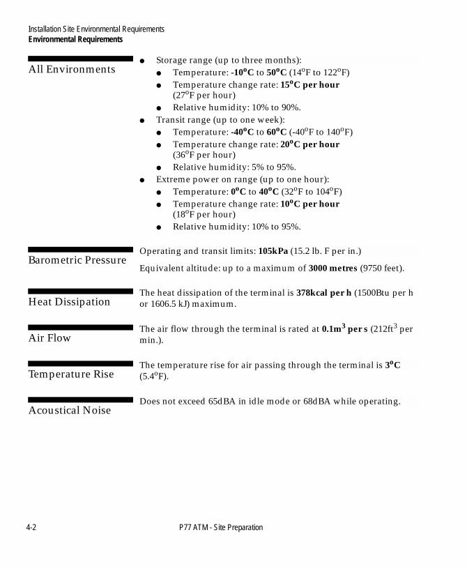
All Environments 4
● Storage range (up to three months):● Temperature: -10oC to 50oC (14oF to 122oF)● Temperature change rate: 15oC per hour
(27oF per hour)● Relative humidity: 10% to 90%.
● Transit range (up to one week): ● Temperature: -40oC to 60oC (-40oF to 140oF) ● Temperature change rate: 20oC per hour
(36oF per hour) ● Relative humidity: 5% to 95%.
● Extreme power on range (up to one hour): ● Temperature: 0oC to 40oC (32oF to 104oF)● Temperature change rate: 10oC per hour
(18oF per hour)● Relative humidity: 10% to 95%.
Barometric Pressure 4
Operating and transit limits: 105kPa (15.2 lb. F per in.)
Equivalent altitude: up to a maximum of 3000 metres (9750 feet).
Heat Dissipation 4
The heat dissipation of the terminal is 378kcal per h (1500Btu per h or 1606.5 kJ) maximum.
Air Flow 4
The air flow through the terminal is rated at 0.1m3 per s (212ft3 per min.).
Temperature Rise 4
The temperature rise for air passing through the terminal is 3oC (5.4oF).
Acoustical Noise 4
Does not exceed 65dBA in idle mode or 68dBA while operating.
4-2 P77 ATM - Site Preparation

Table of ContentsDecals
Book.bk Page iii Tuesday, November 6, 2001 2:04 PM
P77 ATM - Site Preparation
Chapter 5
Decals
Decal Specifications 5-1Card Accept 5-2Card Orientation Decal 5-3Exit/Entry Slot Decals 5-4
P77 Example Decals 5-4Recommended Icon, Text and Braille Placement 5-5

Table of ContentsDecals
Book.bk Page iv Tuesday, November 6, 2001 2:04 PM
P77 ATM - Site Preparation

Book.bk Page 1 Tuesday, November 6, 2001 2:04 PM
P77 ATM - Site Preparation
-15Decal SpecificationsDecalsE
Decal Specifications 5
This following illustration shows the approximate locations for the decals which you may wish to fit to the front of your P77.
Specifications and guidelines for the various decals are given in the following sections.
Cash
Card Insert
Card AcceptWindow
Receipt
Card OrientationWindow

DecalsDecal Specifications
Book.bk Page 2 Tuesday, November 6, 2001 2:04 PM
Card Accept 5
The Card Accept decal, which is typically used to provide the consumer with information on card acceptance, surcharging or general advertising should conform to the following dimensions:
The insert should be a maximum of 0.8mm (0.031 in.) thick. NCR recommend that the insert be made from one of the following materials:
● Polycarbonate● Polyester● Paper.
3mm (0.12in.) radius on all corners
111mm(4.37in.)
95mm(3.74in.)
5-2 P77 ATM - Site Preparation

DecalsDecal Specifications
Book.bk Page 3 Tuesday, November 6, 2001 2:04 PM
Card Orientation Decal 5
If the Card Reader Module window is to be customised to indicate card orientation. The card/decal to be inserted should be a maximum of 0.75mm (0.029 in.) thick and conform to the following dimensions:
Note: These are the dimensions of the industry-standard credit card.
3mm (0.12in.) radius on all corners
86mm(3.35in.)
54mm(2.12in.)
P77 ATM - Site Preparation 5-3

DecalsDecal Specifications
Book.bk Page 4 Tuesday, November 6, 2001 2:04 PM
Exit/Entry Slot Decals 5
Decals can be used to identify the exit/entry slots for the receipt printer, cash dispenser and card entry. The decal should be a maximum of 0.5mm (0.02 in.) thick and it is recommended that it is made from Textured Polycarbonate with 3M 467 High Performance MP adhesive.
Note: A combination of your application and screen graphics can be used as an alternative to indicate the exit/entry slots.
P77 Example Decals 5
The following decals are only a guide and financial institutions may wish to design their own.
Note: The overall dimensions given on these decals are the dimensions of the decal recesses on the P77.
12.5 mm(0.49 in.)
Receipt
12.5 mm(0.49 in.)
120 mm (4.72 in.)
95 mm (3.74 in.)
86 mm (3.39 in.)Card Insert
12.5 mm(0.49 in.)
4 mm(0.16 in.)
55 mm (2.17 in.)
Cash
5-4 P77 ATM - Site Preparation

DecalsDecal Specifications
Book.bk Page 5 Tuesday, November 6, 2001 2:04 PM
On the P77, the MEIs are within the decal location recesses, this has to be considered when designing decals. The following are recommendations only:
● if the background of the decal is transparent the decal can be the full depth 12.5mm (0.49in.) with/without a section (55mm (2.17in.) x 4mm (0.16in.) - the dotted area shown on the decals) cut out for the MEI.
● if a coloured background is required: ● the decal can be full depth 12.5mm (0.49in.) with a section
(55mm (2.17in.) x 4mm (0.16in.) - the dotted area shown on the decals) cut out for the MEI.
or
● the decal can be 8mm (0.32in.) deep and be positioned along the top of the MEI.
Recommended Icon, Text and Braille Placement 5
10 mm(0.4 in.)
10mm(0.4 in.)
10mm(0.4 in.)Icon
braille registered right
1.5mm(0.06 in.)
1.5mm(0.06 in.)
4.5mm(0.18 in.)
4mm9mm
(0.16 in.) to base linewith (0.35 in.) to ascender
P77 ATM - Site Preparation 5-5

DecalsDecal Specifications
Book.bk Page 6 Tuesday, November 6, 2001 2:04 PM
5-6 P77 ATM - Site Preparation
Table of ContentsTransient Protection
Book.bk Page vii Tuesday, November 6, 2001 2:04 PM
P77 ATM - Site Preparation
Appendix A
Transient Protection
AC Power Line Transient Protection A-1
Data Line Transient Protection A-3

Table of ContentsTransient Protection
Book.bk Page viii Tuesday, November 6, 2001 2:04 PM
P77 ATM - Site Preparation
Book.bk Page 1 Tuesday, November 6, 2001 2:04 PM
P77 ATM - Site Preparation A
-1AC Power Line Transient ProtectionTransient ProtectionA
AC Power Line Transient Protection A
In the process of power distribution, transient electrical energy (including, but not limited to, lightning strikes, intermittent short circuits, and switching transients) can be introduced on to power lines. Such transient energy can be very damaging to electronic hardware and can also cause data corruption. Under these circumstances, NCR recommends the use of a.c. power transient suppressors and data (communication) line transient suppressors. Such protective devices are intended to guard against power and data line transients that can result in hardware damage and various system or program errors.
Improvement of any deficiencies in power quality is a customer responsibility. Malfunction and/or component failure as a result of power quality problems are/is not covered by NCR Maintenance Agreement, NCR accepts no liability for any such occurrence nor for its consequences.
When power transient suppression is required, the suppressors used should meet the following minimum requirements:
Transient ProtectionAC Power Line Transient Protection
Book.bk Page 2 Tuesday, November 6, 2001 2:04 PM
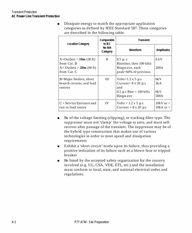
● Dissipate energy to match the appropriate application categories as defined by IEEE Standard 587. These categories are described in the following table:
● Be of the voltage limiting (clipping), or tracking filter type. The suppressor must not ‘clamp’ the voltage to zero, and must self-recover after passage of the transient. The suppressor may be of the hybrid type construction that makes use of various technologies in order to meet speed and dissipation requirements
● Exhibit a ‘short circuit’ mode upon its failure, thus providing a positive indication of its failure such as a blown fuse or tripped breaker
● Be listed by the accepted safety organization for the country involved (e.g. UL, CSA, VDE, ETL, etc.) and the installation must conform to local, state, and national electrical codes and regulations.
Location CategoryComparable
to IECNo 664
Category
Transient
Waveform Amplitudes
A=Outlets > 10m (30 ft)from Cat. BA= Outlets > 20m (60 ft) from Cat. C
II 0.5 sRisetime, then 100 kHzRingwave, eachpeak=60% of previous
6 kV
200A
B=Major feeders, shortbranch circuits, and load centres
III Volts=1.3 x 5 sCurrent= 8 x 20 sand0.5 s Rise = 100 kHz Ringwave
6kV3kA
6kV500A
C = Service Entrance and run to load centre
IV Volts = 1.2 x 5 sCurrent = 8 x 20 s
10kV or >10kA or >
µ
µµ
µ
µµ
A-2 P77 ATM - Site Preparation

Transient ProtectionData Line Transient Protection
Book.bk Page 3 Tuesday, November 6, 2001 2:04 PM
Data Line Transient Protection A
The nature of the transient phenomenon may extend to the data communication lines connected to this equipment. It is the responsibility of the customer to install and connect a data line transient suppression system to correct or prevent any deficiencies. Such systems must meet the following minimum requirements:
● Be of the voltage limiting type and must self-recover after passage of the transient
● Exhibit a ‘short circuit’ mode upon its failure to insure a positive indication of its failure
● Insert less than 5 ohms resistance and minimal inductive and capacitive loading at the operating frequency, in each data line in order to avoid signal degradation
● Be installed in accordance with all applicable local, state, and national electrical codes and regulations.
Note: In certain countries, NCR is able to supply both power and data line transient suppressors as well as a comprehensive line of power conditioning equipment. For application data, contact your NCR Customer Services Division Representative.
P77 ATM - Site Preparation A-3

Transient ProtectionData Line Transient Protection
Book.bk Page 4 Tuesday, November 6, 2001 2:04 PM
A-4 P77 ATM - Site Preparation
Table of ContentsPower Protection
Book.bk Page v Tuesday, November 6, 2001 2:04 PM
P77 ATM - Site Preparation
Appendix B
Power Protection
NCR Power Protection and Cabling Products B-1AC Power Line Transient Protection B-1Data Line Transient Protection B-2Uninterruptible Power Supplies B-2
On-line UPS B-2Enhanced Line-Interactive UPS B-3Line-Interactive UPS B-4
Contact Information B-4

Table of ContentsPower Protection
Book.bk Page vi Tuesday, November 6, 2001 2:04 PM
P77 ATM - Site Preparation
Book.bk Page 1 Tuesday, November 6, 2001 2:04 PM
P77 ATM - Site Preparation B
-1NCR Power Protection and Cabling ProductsPower ProtectionB
NCR Power Protection and Cabling Products B
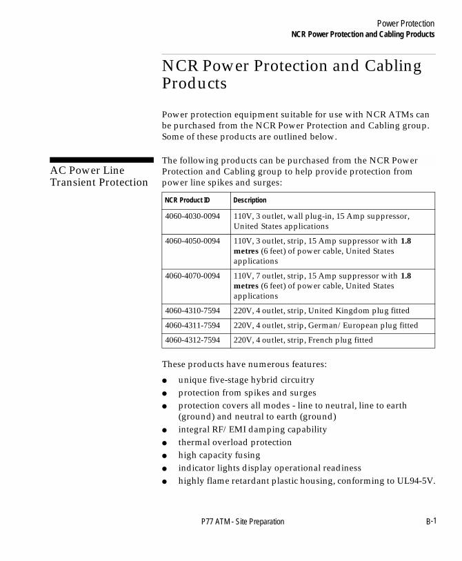
Power protection equipment suitable for use with NCR ATMs can be purchased from the NCR Power Protection and Cabling group. Some of these products are outlined below.
AC Power Line Transient Protection B
The following products can be purchased from the NCR Power Protection and Cabling group to help provide protection from power line spikes and surges:
These products have numerous features:
● unique five-stage hybrid circuitry● protection from spikes and surges● protection covers all modes - line to neutral, line to earth
(ground) and neutral to earth (ground)● integral RF/EMI damping capability● thermal overload protection● high capacity fusing● indicator lights display operational readiness● highly flame retardant plastic housing, conforming to UL94-5V.
NCR Product ID Description
4060-4030-0094 110V, 3 outlet, wall plug-in, 15 Amp suppressor, United States applications
4060-4050-0094 110V, 3 outlet, strip, 15 Amp suppressor with 1.8 metres (6 feet) of power cable, United States applications
4060-4070-0094 110V, 7 outlet, strip, 15 Amp suppressor with 1.8 metres (6 feet) of power cable, United States applications
4060-4310-7594 220V, 4 outlet, strip, United Kingdom plug fitted
4060-4311-7594 220V, 4 outlet, strip, German/European plug fitted
4060-4312-7594 220V, 4 outlet, strip, French plug fitted
Power ProtectionNCR Power Protection and Cabling Products
Book.bk Page 2 Tuesday, November 6, 2001 2:04 PM
Data Line Transient Protection B
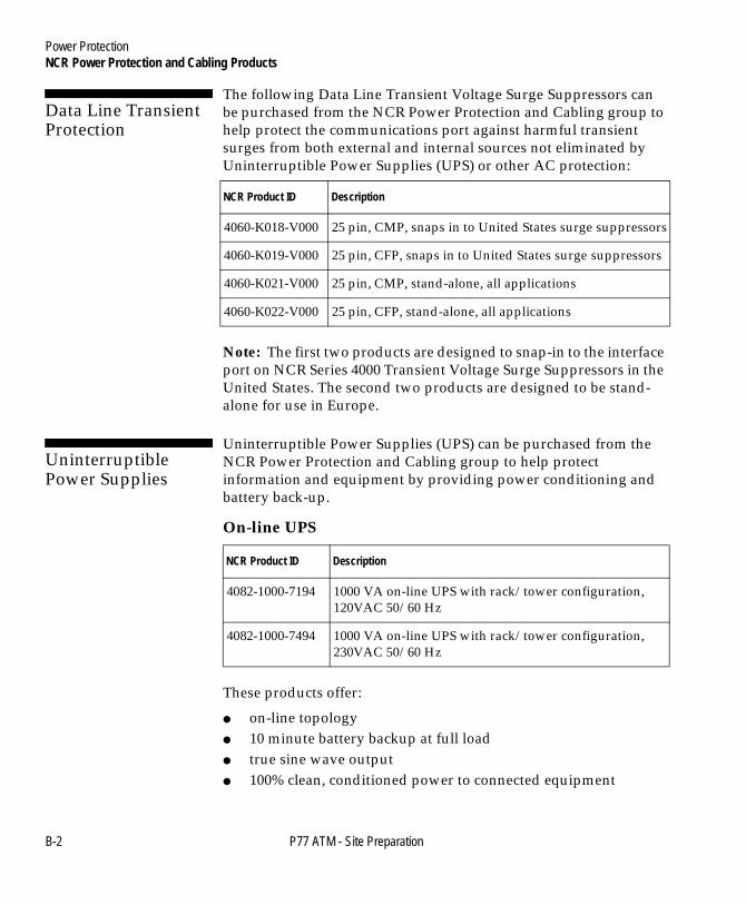
The following Data Line Transient Voltage Surge Suppressors can be purchased from the NCR Power Protection and Cabling group to help protect the communications port against harmful transient surges from both external and internal sources not eliminated by Uninterruptible Power Supplies (UPS) or other AC protection:
Note: The first two products are designed to snap-in to the interface port on NCR Series 4000 Transient Voltage Surge Suppressors in the United States. The second two products are designed to be stand-alone for use in Europe.
Uninterruptible Power Supplies B
Uninterruptible Power Supplies (UPS) can be purchased from the NCR Power Protection and Cabling group to help protect information and equipment by providing power conditioning and battery back-up.
On-line UPS B
These products offer:
● on-line topology● 10 minute battery backup at full load● true sine wave output● 100% clean, conditioned power to connected equipment
NCR Product ID Description
4060-K018-V000 25 pin, CMP, snaps in to United States surge suppressors
4060-K019-V000 25 pin, CFP, snaps in to United States surge suppressors
4060-K021-V000 25 pin, CMP, stand-alone, all applications
4060-K022-V000 25 pin, CFP, stand-alone, all applications
NCR Product ID Description
4082-1000-7194 1000 VA on-line UPS with rack/tower configuration, 120VAC 50/60 Hz
4082-1000-7494 1000 VA on-line UPS with rack/tower configuration, 230VAC 50/60 Hz
B-2 P77 ATM - Site Preparation
Power ProtectionNCR Power Protection and Cabling Products
Book.bk Page 3 Tuesday, November 6, 2001 2:04 PM
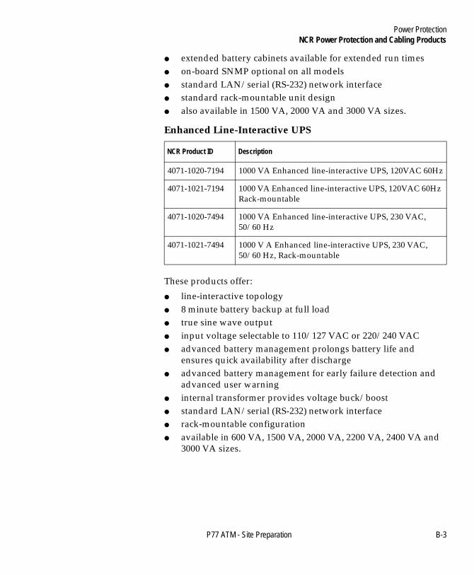
● extended battery cabinets available for extended run times● on-board SNMP optional on all models● standard LAN/serial (RS-232) network interface● standard rack-mountable unit design● also available in 1500 VA, 2000 VA and 3000 VA sizes.
Enhanced Line-Interactive UPS B
These products offer:
● line-interactive topology● 8 minute battery backup at full load● true sine wave output● input voltage selectable to 110/127 VAC or 220/240 VAC● advanced battery management prolongs battery life and
ensures quick availability after discharge● advanced battery management for early failure detection and
advanced user warning● internal transformer provides voltage buck/boost● standard LAN/serial (RS-232) network interface● rack-mountable configuration● available in 600 VA, 1500 VA, 2000 VA, 2200 VA, 2400 VA and
3000 VA sizes.
NCR Product ID Description
4071-1020-7194 1000 VA Enhanced line-interactive UPS, 120VAC 60Hz
4071-1021-7194 1000 VA Enhanced line-interactive UPS, 120VAC 60Hz Rack-mountable
4071-1020-7494 1000 VA Enhanced line-interactive UPS, 230 VAC, 50/60 Hz
4071-1021-7494 1000 V A Enhanced line-interactive UPS, 230 VAC, 50/60 Hz, Rack-mountable
P77 ATM - Site Preparation B-3
Power ProtectionNCR Power Protection and Cabling Products
Book.bk Page 4 Tuesday, November 6, 2001 2:04 PM
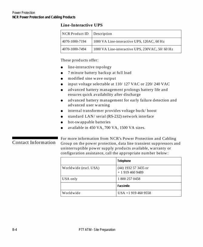
Line-Interactive UPS B
These products offer:
● line-interactive topology● 7 minute battery backup at full load● modified sine wave output● input voltage selectable at 110/127 VAC or 220/240 VAC● advanced battery management prolongs battery life and
ensures quick availability after discharge● advanced battery management for early failure detection and
advanced user warning● internal transformer provides voltage buck/boost● standard LAN/serial (RS-232) network interface● hot-swappable batteries● available in 450 VA, 700 VA, 1500 VA sizes.
Contact Information B
For more information from NCR’s Power Protection and Cabling Group on the power protection, data line transient suppressors and uninterruptible power supply products available, warranty or configuration assistance, call the appropriate number below:
NCR Product ID Description
4070-1000-7194 1000 VA Line-interactive UPS, 120AC, 60 Hz
4070-1000-7494 1000 VA Line-interactive UPS, 230VAC, 50/60 Hz
Telephone
Worldwide (excl. USA) (44) 1932 57 3435 or+ 1 919 460 9489
USA only 1 800 257 0458
Facsimile
Worldwide USA +1 919 460 9558
B-4 P77 ATM - Site Preparation

Index
Book.bk Page 1 Tuesday, November 6, 2001 2:04 PM
P77 ATM - Site Preparation
-1IndexIndex 0
AAbout This Document
Preface viiAC Current Requirement s3-1AC Power Line Transient Protection A-1, B-1Access For All 2-11
Recommended Wheelchair Clearance 2-13Alarm Interface Cable 3-6
Wiring 3-8Americans with Disabilities Act (ADA) 2-11
CCables
Alarm Interface 3-6High Order Communications 3-4High Order Communications Standard (RS-232) 3-4
Canadian Standards Association (CSA) 2-11Clearances
Installation and Service 2-6Communications Requirements 3-4Customer Responsibilities 2-2
DData Line Transient Protection A-3, B-2Decal Specifications 5-1
Card Accept 5-2Card Orientation Decal 5-3Exit/Entry Slots 5-4
DecalsExamples 5-4Icon, Text and Braille Placemen t5-5

Index
Book.bk Page 2 Tuesday, November 6, 2001 2:04 PM
EElectrical Requirements 3-1
Communications Requirements 3-4Power Distribution And Grounding 3-1
EMI Emission 3-3EMI Susceptibility 3-3Environmental Requirements 4-1
Acoustical Noise 4-2Air Flow 4-2All Environment s4-2Barometric Pressure 4-2Heat Dissipation 4-2Temperature And Humidity 4-1Temperature Rise 4-2
FFloor Covering 2-9Floor Loading 2-10
GGrounding Requirements 3-3
HHigh Order Comms Standard Cable (RS-232) 3-4Humidity 4-1
IInput Voltage Setting 3-1Installation Accessories 1-2Installation And Service Clearances 2-6
LLocation Points
Securing Bolts 2-8
NNoise Generation 4-2Normal Operating Range
Interior ATM Environment 4-1
Index-2 P77 ATM - Site Preparation

Index
Book.bk Page 3 Tuesday, November 6, 2001 2:04 PM
PP77
Positioning 2-9Packaging Dimensions 2-4Physical Requirements
Access For All 2-11Customer Responsibilities 2-2Installation And Service Clearances 2-6Overview 2-1Packaging Dimensions 2-4Product Information 2-3Terminal Dimensions 2-5
Planning Check List 1-1Positioning
The P77 2-9Power Cable 3-2Power Protection And Cabling Products B-1
AC Power Line Transient Protection B-1Contact Information B-4Data Line Transient Protection B-2Uninterruptible Power Supplies B-2
Power Quality Distribution And Grounding RequirementsAC Current Requirement s3-1EMI Emission 3-3EMI Susceptibility 3-3Input Voltage Setting 3-1Power Cable 3-2Transient Power Loss 3-3
Preface viiProduct
Class Type 2-3Information 2-3
RRecommended Wheelchair Clearance 2-13
SSecuring Bolts
Location Points 2-8Specifications 2-9
P77 ATM - Site Preparation Index-3

Index
Book.bk Page 4 Tuesday, November 6, 2001 2:04 PM
TTemperature And Humidity 4-1Terminal Dimensions 2-5Transient Power Loss 3-3Transient Protection
AC Power Line A-1Data Line A-3
UUninterruptible Power Supplies B-2
Enhanced Line-Interactiv eB-3Line-Interactive B-4On-line B-2
WWeight 2-10
Index-4 P77 ATM - Site Preparation

NCR welcomes your feedback on this publication. Your comments can be of great value in helping us improve our information products.
You may send your comments, electronically, to the Information Solutions Department at Dundee. See over for details.
Indicate the ways you feel we could improve this publication.
Circle the numbers below that best represent your opinion of this publication.
Ease of use 5 4 3 2 1 0 5 = Excellent
Accuracy 5 4 3 2 1 0 4 = Good
Clarity 5 4 3 2 1 0 3 = Adequate
Completeness 5 4 3 2 1 0 2 = Fair
Organization 5 4 3 2 1 0 1 = Poor
Appearance 5 4 3 2 1 0 0 = Not Applicable
Examples 5 4 3 2 1 0
Illustrations 5 4 3 2 1 0
Job performance 5 4 3 2 1 0
Question resolution 5 4 3 2 1 0
Overall satisfaction 5 4 3 2 1 0
❑ Improve the table of contents ❑ Add more/better quick reference aids
❑ Improve the overview/introduction ❑ Add more examples
❑ Improve the organization ❑ Add more illustrations
❑ Improve the index ❑ Add more step-by-step procedures
❑ Make it less technical ❑ Add more troubleshooting information
❑ Make it more concise/brief ❑ Add more detail
Cut
User Feedback Form
Title: NCR 5877 Personas ATM - Site Preparation
Number: B006-6208- A000 Date:
Book.bk Page 5 Tuesday, November 6, 2001 2:04 PM

Cut
Fold
AffixPostage Stamp Here
Write any additional comments you may have below and on additional sheets, if necessary. Includepage numbers where applicable.
Use the following addresses to send your comments, electronically, to the Information SolutionsDepartment at Dundee:WWW - http://www.ncr.com/product/infoprod/dundeeip/
e-mail - [email protected]
If we may contact you concerning your comments, please fill in the information below:
Thank you for your evaluation of this publication. Fold the form where indicated, tape (please do notstaple), affix stamp and drop in the mail.
F 8763-0695
Name
Organisation:
Company:
Address:
Phone: Fax:
NCR Financial Solutions Ltd.Information SolutionsKingsway WestDundeeScotlandDD2 3XX
Book.bk Page 6 Tuesday, November 6, 2001 2:04 PM


