
NCPP - HBL Power Systems Limited single cell range is designed to comply with IS 10918 & IEC 60623....
12
Single Cell Catalogue Nickel Cadmium Pocket Plate Batteries NCPP
Transcript of NCPP - HBL Power Systems Limited single cell range is designed to comply with IS 10918 & IEC 60623....

®
Single Cell Catalogue
Nickel Cadmium Pocket Plate Batteries
NCPP

Cut-view of cell:
1
Terminal Arrangement
Construction
Introduction:
HBL’s Nickel Cadmium Pocket Plate battery designs are based on the superior pocket plate technology.
A fully integrated modern factory, supported by strong process management and quality controls makes HBL one of the best Nickel Cadmium battery production facilities in the world.
HBL’s single cells are offered in 1.2 voltage per cell and in wide capacity range.
NCPP single cell range is designed to comply with IS 10918 & IEC 60623.
The internal mechanical structure is made of nickel plated steel making it highly rugged and capable of withstanding
mechanical abuses. The active materials are encapsulated between specially designed folded steel strips, which are perforated
on both sides. This design increases the effective surface area by 30% which in turn results in effective utilization of active
material and makes the battery more efficient.
Single cells use special polypropylene separator system, which is chemically inert and highly immune to wear and tear.
Cells come in tough, shock resistant, fusion welded polypropylene containers and lids. A unique flame arresting flip type vent
cap in the cells prevents any unusual event and electrolyte contamination.
Single cells are supplied either in filled condition (charged or discharged) or dry & discharged condition with inter-cell
connectors, cable connectors, associated hardware and accessories that are required for normal operation and maintenance.
Powder coated Mild Steel racks to house the batteries can be provided as an option.
Flame Arresting Vent Cap
Prevents propagation of external flame in to thecell & electrolyte contamination
Nickel-plated components (tab, stud, nut, post)provide excellent electrical conductivity
Prevents electrolyte splashing and possible short-circuit caused by external objects accidentallyfalling into the cell
Splash Guard
Plate Groups Bolted construction under controlled
torque conditions to withstand severe vibrations
Polypropylene Grid Separator
Separates the plates and insulates the frames from each other and allows freeelectrolyte
Translucent Polypropylene Container
Fusion welded to lids, makes the cell mechanicallysturdy and facilitates visual inspection of electrolyte level
Pocket Plate Made of double perforated steel strips, encapsulating the active materials

Benefits
High reliability
Long float life - 20 years+ at 20 C for standby applications
Long shelf life - 5 years+ for the cells supplied in dry condition & 1 year in filled condition
Quick charging - More than 90 % capacity available within 6 hours of charging
Low internal resistance - For enhanced battery performance
Resistant to mechanical & electrical abuses - Making it ideal for deployment in harsh environments
Wide operating temperature range (-20 C to +50 C)
Application specific designs (KPH, KPM & KPL)
Easy installation & low maintenance
Best TCO (Total Cost of Ownership) for demanding application needs
No risk of sudden death failure
Capacity Range
High Discharge - KPH:
Medium Discharge - KPM:
Long Discharge - KPL:
Thick plates with more amount of active material
For long discharge applications, with more than 3 hours backup time requirements
11 Ah to 480 Ah
41standard cell models to choose from
Optimized plate thickness
For medium discharge applications, between 1 to 3 hours backup time requirements which involves high and long discharges
10 Ah to 395 Ah
42 standard cell models to choose from
Thin plates with more plate surface area
For high discharge applications with less than 1 hour backup time requirements
10 Ah to 265 Ah
33 standard cell models to choose from
0
0 0
2

1.43 – 1.50 V/cell
Battery Charging
Following are recommended charge conditions:
Commissioning Charge:
Quick Charging:
Charging in Operation:
Two Level Charging:
Float level:
*Boost level:
The recommended charging voltages for continuous parallel operation,
with occasional battery discharges:
1.40 V/cell for KPH & KPM
1.42 V/cell for KPL
Float charging current: 1 to 2 mA per Ah
(may increase water consumption)
* Refer charge curves at page#13
(A higher voltage will keep the battery at high state of charge)
1.45 to 1.70 V/cell for KPH & KPM
1.47 to 1.70 V/cell for KPL
Current limit: 0.2C5 A
Single Level Charging:
Applications
Fire alarm systems
Signaling and Telecommunications
Solar Photovoltaic
Instrumentation & Process control
Switchgear protection
Emergency lighting
Switchyard
UPS
Genset starting
Diesel Locomotive cranking
Electromagnetic lifters (EOT crane)
3
Constant current charge of 10 hours at 0.2 C5 A (20 amps for 100 Ah battery)
Constant current charge at 0.4 C5 A for first 2.5 hours followed by 0.2 C5 A for next 2.5 hours
Single cell range is specially designed for industrial markets considering the reliability, cost-optimization and low-maintenance requirements for the following applications and segments

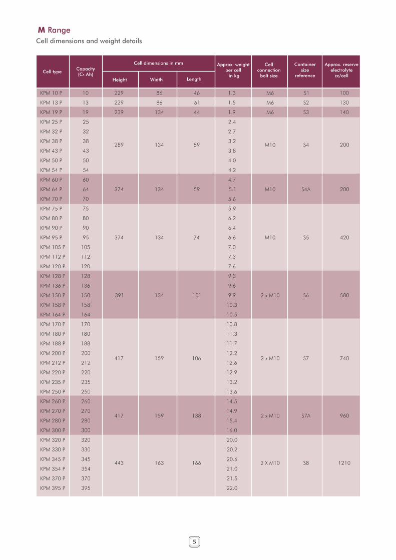
Cell dimensions and weight details
4
H Range
Cell type
LengthWidth
Cell dimensions in mm
Height
Containersize
reference
Cellconnection
bolt size
KPH 10 P
KPH 12 P
KPH 16 P
KPH 20 P
KPH 24 P
KPH 30 P
KPH 35 P
KPH 40 P
KPH 45 P
KPH 50 P
KPH 57 P
KPH 63 P
KPH 69 P
KPH 76 P
KPH 80 P
KPH 85 P
KPH 94 P
KPH 100 P
KPH 110 P
KPH 120 P
KPH 130 P
KPH 140 P
KPH 145 P
KPH 155 P
KPH 160 P
KPH 170 P
KPH 180 P
KPH 190 P
KPH 210 P
KPH 230 P
KPH 240 P
KPH 255 P
KPH 265 P
10
12
16
20
24
30
35
40
45
50
57
63
69
76
80
85
94
100
110
120
130
140
145
155
160
170
180
190
210
230
240
255
265
229
229
239
289
374
374
391
417
417
443
86
86
134
134
134
134
134
159
159
163
46
61
44
59
59
74
101
106
138
166
1.45
1.50
1.90
2.15
3.20
3.55
3.70
4.50
4.80
5.00
6.30
6.50
6.70
6.80
6.85
9.40
9.70
9.80
10.2
10.5
12.5
13.0
13.2
13.6
14.2
14.5
14.9
15.2
20.0
20.8
21.6
22.0
22.4
M6
M6
M6
M10
M10
M10
2 x M10
2 x M10
2 x M10
2 X M10
S1
S2
S3
S4
S4A
S5
S6
S7
S7A
S8
100
130
140
200
200
420
580
740
960
1210
Capacity(C5 Ah)
Approx. weight per cell in kg
Approx. reserveelectrolyte
cc/cell
Cell type
LengthWidth
Cell dimensions in mm
Height
Containersize
reference
Cellconnection
bolt size
Capacity(C5 Ah)
Approx. weight per cell in kg
Approx. reserveelectrolyte
cc/cell
5
Cell dimensions and weight details
M Range
KPM 10 P
KPM 13 P
KPM 19 P
KPM 25 P
KPM 32 P
KPM 38 P
KPM 43 P
KPM 50 P
KPM 54 P
KPM 60 P
KPM 64 P
KPM 70 P
KPM 75 P
KPM 80 P
KPM 90 P
KPM 95 P
KPM 105 P
KPM 112 P
KPM 120 P
KPM 128 P
KPM 136 P
KPM 150 P
KPM 158 P
KPM 164 P
KPM 170 P
KPM 180 P
KPM 188 P
KPM 200 P
KPM 212 P
KPM 220 P
KPM 235 P
KPM 250 P
KPM 260 P
KPM 270 P
KPM 280 P
KPM 300 P
KPM 320 P
KPM 330 P
KPM 345 P
KPM 354 P
KPM 370 P
KPM 395 P
10
13
19
25
32
38
43
50
54
60
64
70
75
80
90
95
105
112
120
128
136
150
158
164
170
180
188
200
212
220
235
250
260
270
280
300
320
330
345
354
370
395
229
229
239
289
374
374
391
417
417
443
86
86
134
134
134
134
134
159
159
163
46
61
44
59
59
74
101
106
138
166
1.3
1.5
1.9
2.4
2.7
3.2
3.8
4.0
4.2
4.7
5.1
5.6
5.9
6.2
6.4
6.6
7.0
7.3
7.6
9.3
9.6
9.9
10.3
10.5
10.8
11.3
11.7
12.2
12.6
12.9
13.2
13.6
14.5
14.9
15.4
16.0
20.0
20.2
20.6
21.0
21.5
22.0
M6
M6
M6
M10
M10
M10
2 x M10
2 x M10
2 x M10
2 X M10
S1
S2
S3
S4
S4A
S5
S6
S7
S7A
S8
100
130
140
200
200
420
580
740
960
1210

Cell type
LengthWidth
Cell dimensions in mm
Height
Containersize
reference
Cellconnection
bolt size
Capacity(C5 Ah)
Approx. weight per cell in kg
Approx. reserveelectrolyte
cc/cell
Cell dimensions and weight details
L Range
6
KPL 11 P
KPL 17 P
KPL 23 P
KPL 27 P
KPL 32 P
KPL 36 P
KPL 41 P
KPL 45 P
KPL 55 P
KPL 60 P
KPL 69 P
KPL 75 P
KPL 80 P
KPL 88 P
KPL 92 P
KPL 100 P
KPL 115 P
KPL 120 P
KPL 135 P
KPL 150 P
KPL 160 P
KPL 170 P
KPL 180 P
KPL 190 P
KPL 210 P
KPL 220 P
KPL 235 P
KPL 255 P
KPL 270 P
KPL 285 P
KPL 300 P
KPL 310 P
KPL 335 P
KPL 355 P
KPL 370 P
KPL 390 P
KPL 410 P
KPL 425 P
KPL 445 P
KPL 460 P
KPL 480 P
11
17
23
27
32
36
41
45
55
60
69
75
80
88
92
100
115
120
135
150
160
170
180
190
210
220
235
255
270
285
300
310
335
355
370
390
410
425
445
460
480
229
229
289
374
374
391
417
417
443
86
86
134
134
134
134
159
159
163
46
61
59
59
74
101
106
138
166
1.4
1.60
1.90
3.20
3.50
3.80
4.20
4.30
4.50
5.00
5.60
5.90
6.10
6.20
6.30
6.40
6.60
6.80
9.50
10.0
10.4
10.7
11.0
12.5
12.8
13.0
13.5
13.8
14.0
14.3
18.0
18.4
18.8
19.2
21.5
22.0
22.4
22.6
22.9
23.2
23.5
M6
M6
M10
M10
M10
2 x M10
2 x M10
2 x M10
2 X M10
S1
S2
S4
S4A
S5
S6
S7
S7A
S8
100
130
200
200
420
580
740
960
1210

2STEPContainer
sizereference
1TIER 2TIER
4STEP 3STEP1STEP 4STEP3STEP 2STEP1STEP
W W W W H H W H H W H H H W W H
Evaluation of Rack Length
Length of rack = (X + 1) x No. of cells in a row for S1 to S5 containers
= (X + 2) x No. of cells in a row for S6 to S8 containers
Where, X = Length of cell
The value of length should be rounded-off to nearest to 50 mm and 5 mm should be added to arrive at the final length of rack.
Normal Arrangement
(NORMAL ARRANGEMENT)
S1 & S2
S3
S4
S4A
S5
S6
S7
S7A
S8
Battery Arrangement as per Standard Rack Designs
7
222
318
318
318
318
318
368
368
376
318
318
318
318
318
368
368
376
323
467
467
467
467
467
542
542
554
467
467
467
467
467
542
542
554
424
616
616
616
616
616
716
716
732
616
616
616
616
616
716
716
732
668
678
728
813
813
830
856
856
882
1070
1250
1450
1450
1470
1550
1550
1650
783
793
843
928
928
945
971
971
997
1300
1450
1670
1670
1700
1760
1760
1860
898
908
958
1043
1043
1060
1086
1086
1112
1550
1700
1900
1900
1950
2000
2000
2100
Standard Arrangement of Cells
KPH 10 - KPH 80
KPM 10 - KPM 120
KPL 11 - KPL 120
KPH 85 - KPH 265
KPM 128 - KPM 395
KPL 135 - KPL 480
(All dimensions in mm. Height is including cells)

Battery Rack Arrangement
TWO TIER RACK
3STEP 2TIER RACK
SINGLE TIER RACK
4STEP 1TIER RACK
TWO TIER RACK
2STEP 2TIER RACK
TWO TIER RACK
4STEP 2TIER RACK
8
SINGLE TIER RACK2STEP 1TIER RACK
H
W
L
SINGLE TIER RACK3STEP 1TIER RACKS
H
W
L
W
H
L
W
H
L
W
H
L
H
w
L

Typical Characteristics
10 20 30 40 50 60 70 80 90 100
1.4
1.3
1.2
1.1
1.0
0.9
0.8
0.7
0.6
0.5
0.2C A5
0.1C A5
2C A5
0.5C A5
1C A5
Volts/Cell
% in Capacity
KPMKPM Discharge
I/C
0.2
0.1
100
7
76
5Available Capacity %
1
2 3 4
12
6
45
Current
3
1 2 5 10 20 50 Hours
50
Charging Voltage
1. 1.40 Volts / Cell2. 1.45 Volts / Cell3. 1.50 Volts / Cell4. 1.55 Volts / Cell5. 1.60 Volts / Cell6. 1.65 Volts / Cell7. 1.70 Volts / Cell
Amp. %
KPMKPM Charge
1C A5
2C A5
0.2C A5
0.5C A5
10 20 30 40 50 60 70 80 90 100
1.4
1.3
1.2
1.1
1.0
0.9
0.8
0.7
0.6
0.5
Volts/Cell
3C A5
5C A5
% in Capacity
KPH DischargeKPH
I/C
0.2
0.1
1 2 5 10 20 50 Hours
Amp.
100
7
7 6
5 Available Capacity %1 2 3 4
2
16
4
5
Current
3
50
Charging Voltage
1. 1.40 Volts / Cell2. 1.45 Volts / Cell3. 1.50 Volts / Cell4. 1.55 Volts / Cell5. 1.60 Volts / Cell6. 1.65 Volts / Cell7. 1.70 Volts / Cell
%
KPHKPH Charge
KPLKPL
I/C
0.2
0.1
1 2 5 10 20 50 Hours
Amp.
100
7
7
6
5
Available Capacity %
1
234
2
6
4
Current350
5
1
%
Charging Voltage
1. 1.40 Volts / Cell2. 1.45 Volts / Cell3. 1.50 Volts / Cell4. 1.55 Volts / Cell5. 1.60 Volts / Cell6. 1.65 Volts / Cell7. 1.70 Volts / Cell
Charge Discharge
0.1C A5
0.2C A5
0.5C A5
1.4
1.3
1.2
1.1
1.0
0.9
0.8
0.7
0.6
0.5
1C A5
10 20 30 40 50 60 70 80 90 100
Volts/Cell
% in Capacity
KPLKPL Discharge
9

Certifications
Corp
Com
ms /
sin
gle
cell B
rochure
/
2016
April
Road No. 10, Banjara Hills,
www.hbl.inE-mail:[email protected]
712, Brook Street Rocky Hill, CT 06067 www.hblbatteries.com
E-mail:[email protected] +1 860 257 9800
Emilienstraße 24A
Email: [email protected]
www.hblpower.de
Tel: +49 375 390 965 97
Fax: +49 375 390 965 99
08056 ZwickauGermany
HBL Germany GmbH
HBL America Inc.
HBL Power Systems Ltd.
Hyderabad 500034, TG, INDIA


![Ncpp Block[1]](https://static.fdocuments.in/doc/165x107/55cf9d48550346d033acf5f9/ncpp-block1-565dce752dd14.jpg)
