ncerning the Combustion Air the Pyrolysis Boiler - … · 184 Vlastimil Kuběna, Jana Müllerová,...
20
ŚROD Tom Modifi VŠB – VŠB – VŠB – 1. Introduc A boi and environm biomass (wo saw dust, etc used. The op considered to the device, or sibility of ma lump wood a used for the c DKOWO-POMORSK 14. Rok 2 ications Co from – Technical U Universit Jan Va – Technical U Tadeusz H Koszalin Un – Technical U R Universit ction iler or a stove mentally friend ood, wood wa .), fossil fuels peration of bo o be a great ad r manual, whi anual control o are called woo combustion of KIE TOWARZYSTW Rocznik Ochro 2012 oncerning the Pyroly Vlastimil Ku University of O Jana Müller ty of Žilina, S líček, Marta University of O Hryniewicz, K niversity of Te Vojtěch Vác University of O Roman Micha ty of Žilina, S e is a device, dly source in ste, straw, hay (coal, petroleu oilers can be e dvantage just ch means that of fuel feeding od gasification f biomass, mo WO NAUKOWE OCH ona Środowiska ISSN 1506-2 g the Comb ysis Boiler uběna Ostrava, Czec rová Slovak Republ Harničárová Ostrava, Czec Krzysztof Roko echnology, Po clavík Ostrava, Czec alovič Slovak Republ which is used order to heat y, shavings, c um derivates, g either fully au in time when an operator n g [1]. Boilers th n boilers. The ostly hard dry w HRONY ŚRODOWI 218X 182– bustion Ai r ch Republic lic á ch Republic osz oland ch Republic lic d as an econom a place. As a chippings, cutt gas), and other utomated, whi n we cannot co needs to have a hat burn and g se devices are wood (beech, ISKA –201 ir mical a fuel, tings, rs are ich is ontrol a pos- gasify e also oak).
Transcript of ncerning the Combustion Air the Pyrolysis Boiler - … · 184 Vlastimil Kuběna, Jana Müllerová,...

ŚROD
Tom
Modifi
VŠB –
VŠB –
VŠB –
1. IntroducA boi
and environmbiomass (wosaw dust, etcused. The opconsidered tothe device, orsibility of malump wood aused for the c
DKOWO-POMORSK
14. Rok 2
ications Cofrom
– Technical U
UniversityJan Va
– Technical UTadeusz H
Koszalin Un
– Technical UR
University
ction iler or a stovementally friendood, wood wa.), fossil fuels peration of boo be a great adr manual, whianual control oare called woocombustion of
KIE TOWARZYSTW
Rocznik Ochro2012
oncerningthe Pyroly
Vlastimil KuUniversity of O
Jana Müllerty of Žilina, Slíček, Marta H
University of OHryniewicz, Kniversity of Te
Vojtěch VácUniversity of ORoman Michaty of Žilina, S
e is a device, dly source in ste, straw, hay(coal, petroleu
oilers can be edvantage just ch means that of fuel feedingod gasificationf biomass, mo
WO NAUKOWE OCH
ona Środowiska ISSN 1506-2
g the Combysis Boiler
uběna Ostrava, Czecrová
Slovak RepublHarničárováOstrava, Czec
Krzysztof Rokoechnology, Poclavík Ostrava, Czecalovič
Slovak Republ
which is usedorder to heat y, shavings, cum derivates, geither fully auin time whenan operator n
g [1]. Boilers thn boilers. Theostly hard dry w
HRONY ŚRODOWI
218X 182–
bustion Air
ch Republic
lic á ch Republic osz oland
ch Republic
lic
d as an economa place. As a
chippings, cuttgas), and otherutomated, whi
n we cannot coneeds to have ahat burn and gse devices arewood (beech,
ISKA
–201
ir
mical a fuel, tings, rs are ich is ontrol a pos-gasify e also oak).

Modifications Concerning the Combustion Air from the Pyrolysis Boiler 183
Wet wood is not very suitable because it burns poorly, which causes con-siderable losses, and if water vapour condenses on interior parts of the device, this may lead to corrosion and device failure. The moisture con-tent of wood billets for heating purposes should not exceed 20%; never-theless, every boiler manufacturer demonstrates this value in product user manuals, so it is recommended to follow the instructions of the manufac-turer [2]. If wood is dry enough to burn, it can generate considerable heat. A consequent reduction in the amount of air to the boiler would probably cause higher tarring; to prevent that, many users keep the fire burning by using extra-dry firewood [3]. The use of a particular type of biomass depends on its chemical and physical properties. Biomass mate-rials can have a wide range of moisture content. High water content in fuels tends to increase the consumption of energy that is required to evaporate the water. The high moisture of biofuels has a negative impact on formation of an arch in fuel storage bins, flue gas volume, amount of water vapour in the flue gas, flue gas dew point temperature increase, and on an increased risk of corrosion on some parts of combustion equip-ment. This is reflected in the combustion equipment design.
The elemental composition of biomass is not very different from that of other solid fuels. The most important task is to monitor carbon, hy-drogen and oxygen proportions in dry matter [4]. In contrast to fossil fuels, biomass contains about twice the amount of oxygen (O2) and smaller amount of carbon (C). The contents of hydrogen (H2) and nitrogen (N2) of fosil fuels and biomass are almost the same. With regard to chemical components, biomass contains also trace amounts of elements that influence the production of combustion pollutants. They are sulphur (S) and chlorine (Cl) [5]. Individual fuels differ from each other in the content of substances influencing the production of emissions. As compared to fossil fuels, biomass has a very low sulphur content, which has an impact on the total amount of sulphur dioxide; this causes acid rain and smog epi-sodes in villages. Chlorine, if burnt, contributes to the formation of hydro-chlorid acid (HCl) and dioxins (PCDD/PCDF), and occurs mainly in cereal straw and hay, which is given by the use of fertilizers in agriculture. In biomass, so-called inorganic trace elements affecting indirectly the com-bustion process, pollutant formation, creation of deposits, and others are contained too. These elements are lead (Pb), potassium (K), sodium (Na), calcium (Ca), silicon (Si), etc. [6]. When burning fossil fuels as well as

184 Vlastimil Kuběna, Jana Müllerová, Jan Valíček, et al.
biomass, emissions are released into the air. The average production of ash from wood biomass combustion is approx. 0.4 to 0.7% by weight of burnt wood and approx. 1.5–3% by weight of burnt bark. When burning wood with a volume of 1m3, 3 to 5 kg of ash are produced. Ash matter in the firebox cannot be sintered below the temperature of 1100°C, and ash in the form of bulk materials can be used as natural fertilizer, because it contains oxides of calcium, potassium, magnesium and phosphorus. Safety of bio-mass combustion in hot water boilers has a large influence on human health and safety [7].
2. The state of the art Biomass is mainly known as firewood (logs), sawdust, wood
shavings, wood chips, and a product that is made of them for heating purposes in the form of pellets and briquettes. Their efficient combustion requires a modern technology; many of these fuels have a high moisture content. Others, such as sawdust and straw require a different combustion process owing to their properties. A classic stove cannot effectively use a wood gas that is produced by thermal gasification. Modern technolo-gies came with the double chamber combustion of wood resulting in in-creased combustion efficiency (i.e. lower fuel consumption) and espe-cially in a high level of output controllability while maintaining rated efficiency [8].
With the problems of domestic and local boilers mainly companies manufacturing their products only in their countries (some only in their surroundings) tackle. So each company develops its own facilities, which are very similar to those of competitors; each of them having its own know-how. Current research in these facilities focuses on the efficiency of the combustion process, which ranges from 80% to 90% [9]. A gasifica-tion system is very economical; it delivers fuel savings of up to 40%. This method is introduced as another alternative to innovation. The determina-tion of system performance and concentration of emissions from gasifica-tion boilers has been so far provided only by specialized services at the request of manufacturers and users. The measurement itself is laborious, time consuming, and therefore relatively expensive. It requires the use of special and expensive aids and measuring instruments [10].

Modifications Concerning the Combustion Air from the Pyrolysis Boiler 185
3. The experimental procedure A hot water boiler of the type MA23 for lump wood gasification
with the output of 23 kW (Fig. 1) was subject to output, emissions and safety testing. The boiler is equipped with its own electronic temperature controller and a temperature safety fuse. The boiler status and its equip-ment were tested in accordance with current technical documentation supplied by the manufacturer. Spruce wood with a moisture content of 20% and a calorific value of 15.266 MJ⋅kg-1 was used for experimental purposes. Air temperature in a test room as well as temperature of air being sucked into the combustion chamber was 22.15°C on an average. An exhaust throat of the hot water boiler with a diameter of 150 mm was connected to a section for gas measurement and associated with a chim-ney of 6 m height and 300 mm diameter. When determining the heat out-put, boiler efficiency, combustion time, components in the combustion gas and exit-flue gas temperature, the boiler was operated at the heat out-put in its output range throughout testing. All tests of the hot water boil-ers were conducted at the Faculty of Mechanical Engineering in Žilina (Department of Power Engineering) having necessary modern and testing equipment. The thermal efficiency of the hot water boiler tested was evaluated by a direct method. The test of hot water boilers consists of tests to determine the capacity, including an operational safety test for combustion equipment verifying the thermal overload resistance of the boiler. To evaluation parameters of the tests belong the efficiency, emis-sion conversion, functionality test of the surplus heat removing equip-ment. There is a requirement for low-emission combustion in boilers op-erated even at low heat output capacity, which shall not be less than 40% of the rated heat output capacity. The hot water boiler being under test is placed on a weighing machine owing to the measurement of fuel con-sumption. A throat for the evacuation of combustion gases is connected to an isolated section for flue gas measurement with measuring points for measuring the flue gas temperature (chimney temperature), chimney draught, flue gas composition (carbon dioxide, oxygen, carbon monox-ide, nitrogen monoxide and also NOx), and for taking the samples of the unburnt solid particles. To keep the draught constant, an exhaust fan for venting is placed there. Its speed is regulated by a frequency converter. The flue gas temperature is measured by a temperature sensor located

186
inside a probone of them iare located wfrom the edga spectral anmonoxide (Cide (SO2) usmethod). An(O2) and nitrtrations weretemperature omass boilers)to a unit of mlowing relaticontent of sovimetric methratuses as giv
Fig. 1. The hoRys. 1. Kocioł
Vlastimil Kub
be sucking the is placed in thewithin one quage of the wallnalyzer PHOTCO), carbon dising a technoln electrochemirogen dioxide e converted toof 273.15 K) a). A mean valumass [mg·m-3]ons: ΡCO = 1.
olids in the fluhod. The measven in [11].
ot water boiler Mł MA 23 do wod
ěna, Jana Mülle
flue gas. The e middle of tharter distance l. The flue ga
TON evaluatinioxide (CO2), logy known aical sensor w(NO2) concen
o standard conand the refereue of the volum], whereas for25 kg (n) m-3
ue gas was msurement of so
MA 23 – test prody gorącej − po
erová, Jan Valíč
probe has three smoke-flue dof the smoke-s composition
ng the concennitric oxide (N
as NDIR (nonas used to evntrations. The
nditions (pressnce oxygen come emissions r calculations , ΡNO2 = 2.05
measured and eolids was carri
obe connection ołączenia testow
ček, et al.
ee sampling poduct. The othe-flue duct diamn was measurentrations of caNO), sulphur
ndispersive infvaluate the ox
measured conure of 1013.2ontent (6% for[ppm] is convwere used thetype Isostack
evaluated by aied out using a
[14]
we [14]
oints; er two meter ed by arbon diox-
frared xygen ncen-
25 Pa, r bio-verted e fol-
k. The a gra-appa-

Modifications Concerning the Combustion Air from the Pyrolysis Boiler 187
Each of the tests lasted 240 minutes; no external intervention, the boiler stoked once. For maintaining the rated output, a standard elec-tronic control unit that was part of the boiler was used. The unit controls the boiler on the basis of measurement of outlet water temperature. 4. The hot water boiler MA23
The hot water boiler MA23 (Fig. 2) belongs to the gasification boilers for combustion of dry lump wood. Owing to its output it is in-tended primarily for the heating of family houses, cottages, small office buildings and other small buildings. The maximum required heat output is 23 kW. The boiler works on the principle of fuel gasification. The boiler consists of two chambers that are placed one above the other. The upper chamber serves as a fuel hopper with a process of burning away. The lower serves as a combustion chamber and ashtray. This type of boiler can be regulated by the combustion air. The hot water boiler is made of steel. At the bottom of the combustion chamber there is an after-burner chamber, in which a refractory concrete deflector is placed. The combustion air intake is realized by using a radial fan. In addition, com-bustion in hot water boilers must be safe; emissions will be low, while the minimum heat output capacity will not be greater than 30% of the rated heat output capacity of hot water boilers. The minimum value of the heat output capacity may be higher in hot water boilers with manual fuel feeding. The amount of heat generated should be determined by the manufacturer. This shall be included in documentation.
The boiler provides fuel pre-drying with subsequent gasification at a high temperature. Both the primary and the secondary air flow are preheated and then distributed in a desired, ideal proportion to the boiler firebox and to the nozzle.
The primary combustion air is driven into the combustion cham-ber through the space beneath the upper door. An even distribution of the preheated primary air ensures that only smaller amounts of fuel are gas-ified. Therefore, the boiler is highly economical and has a high heating coefficient of performance – 85–89% throughout the output capacity range. This design enables a more efficient gasification of rather large pieces of wood. The secondary air that is driven into the gasification nozzle is preheated to a high temperature. It prevents the flame from be-ing chilled and combustible substances burn well. The lower combustion chamber is equipped with fireproof concrete blocks where the process of

188
burning is cocompletely b
Fig. 2. Hot wachamb6 – ele
Rys. 2. Kociołspalankominbetono
5. The resuBasic
rect method aRepublic, Czignition to ex
Vlastimil Kub
ompleted and urnt.
ater boiler MA2er, 3 – fan, 4 –ctronic controllł MA23 do wodnia, 3 – wentylana, 6 – sterowniowy
ults and discmeasurements
according to rezech Republic xtinction with r
ěna, Jana Mülle
all particles
23, where: 1 – fetube heat exchler, 7 – refractordy gorącej: 1 – kator, 4 – rurowyik elektroniczny
cussion s were carried elevant standarand European regard to the n
erová, Jan Valíč
that fall down
eed chamber, 2hanger, 5 – chimry concrete deflkomora zasilani
y wymiennik ciy, 7 – żaroodpor
out using the rds and regulatUnion. In the
need to compa
ček, et al.
n to this spac
– combustion
mney neck, lector ia, 2 – komora iepła, 5 – szyjkrny deflektor
direct and thetions for the S
e whole extent are modificatio
ce are
ka
e indi-lovak from
ons of

Modifications Concerning the Combustion Air from the Pyrolysis Boiler 189
the fitting, we chose for evaluation a range of temperatures of water being heated from 60°C to 90°C, i.e. the working range of temperatures at which the boiler was operated most frequently. We were interested in the meas-urement of amounts of CO (product of incomfortable combustion), boiler output and temperature of outlet water depending on the temperature of the flue gas. A record of the measured carbon monoxide production for the first experimental measurements of rated heat output of the gasification boiler showed very disappointing results. As can be seen in Fig. 3, the mean value of carbon monoxide (CO) concentration was almost 8000 mg·m-3 in the case of boiler stoked with fuel twice.
Fig. 3. Data from measurement in a case of the original fitting Rys. 3. Charakterystyka urządzenia/kotła oryginalnego
The mean value of carbon monoxide concentration in the case of
boiler stoked twice (original fiftting, see Fig. 4) without modification of the combustion air distribution was 2.072 mg·m-3.
The gasification boiler had to undergo modification concerning the combustion air and gas intake (Fig. 5) into the secondary combustion zone, see 7 in Fig. 2.

190
The ndistribution) secondary cocombustion mflue gas. Thecarbon monoresult was ex
Fig. 4. The oriRys. 4. Urządz
Fig. 5. The newRys. 5. Nowo
Vlastimil Kub
newly designehas orifices al
ombustion air modification le change in theoxide concentrxpected and co
iginal fitting zenie oryginaln
w designed fittizaprojektowan
ěna, Jana Mülle
ed fitting (firelong the longeand gas from
leads to a lowe fitting is refration with an nfirmed by me
ne
ing e urządzenie
erová, Jan Valíč
eproof shaped er side intendem the combuswer productioflected in the m
average of 13easuring.
ček, et al.
piece used foed for the intastion chamber.n of the meameasured valu375.7 mg·m-3.
or air ake of . The sured
ues of This
Modifications Concerning the Combustion Air from the Pyrolysis Boiler 191
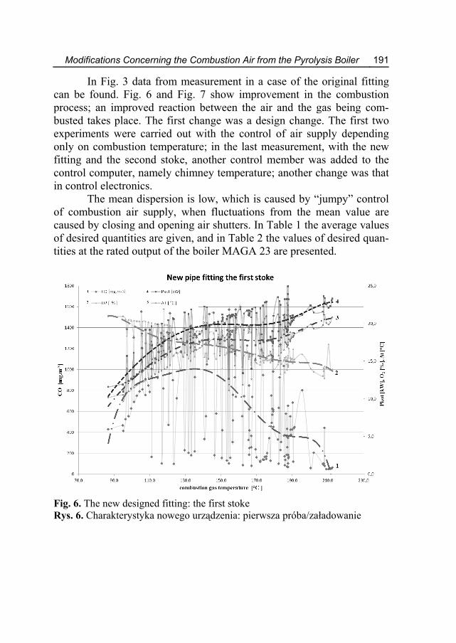
In Fig. 3 data from measurement in a case of the original fitting can be found. Fig. 6 and Fig. 7 show improvement in the combustion process; an improved reaction between the air and the gas being com-busted takes place. The first change was a design change. The first two experiments were carried out with the control of air supply depending only on combustion temperature; in the last measurement, with the new fitting and the second stoke, another control member was added to the control computer, namely chimney temperature; another change was that in control electronics.
The mean dispersion is low, which is caused by “jumpy” control of combustion air supply, when fluctuations from the mean value are caused by closing and opening air shutters. In Table 1 the average values of desired quantities are given, and in Table 2 the values of desired quan-tities at the rated output of the boiler MAGA 23 are presented.
Fig. 6. The new designed fitting: the first stoke Rys. 6. Charakterystyka nowego urządzenia: pierwsza próba/załadowanie

192 Vlastimil Kuběna, Jana Müllerová, Jan Valíček, et al.
Fig. 7. The new designed fitting: the second stoke Rys. 7. Charakterystyka nowego urządzenia: druga próba/załadowanie Table 1. Average values of desired quantities Tabela 1. Średnie wartości pożądanych/badanych wielkości
Unit Original condition
New fitting 1D
New fitting 2D
Pkot kW 19.2 19.3 18.5 CO mg⋅m-3 2072.0 660.8 696.3 O2 % 16.6 16.5 18.2 NOx mg⋅m-3 115.2 120.4 90.9 Outlet temperature °C 79.6 79.3 79.4 Chimney temperature °C 154.3 156.6 145.9 Temperature gradient °C 17.2 17.3 16.6

Modifications Concerning the Combustion Air from the Pyrolysis Boiler 193
Table 2. Values of desired quantities at rated output Tabela 2. Wartości pożądanych wielkości przy mocy znamionowej
Original condition
New fitting 1D
New fitting 2D
Pkot kW 23.06 23.06 23.06 CO mg⋅m-3 92 54 62 O2 % 13.83 13.8 16.26 NOx mg⋅m-3 136.9 244.2 157.5 Outlet temperature °C 83.5 83.5 88.4 Chimney temperature °C 212.6 212.2 200.1 Temperature gradient °C 20.13 20.72 21.02
From the analysis of acquired data, a regression analysis was made
to obtain the description and prediction of dependences and relations be-tween individual parameters. From the performed analyses, the following equations (1) to (10) for dependences were received, see Fig. 8.
Chimney draught on output: 235.78498 2.0755 ; 0.97k kotp P R= + ⋅ = (1)
Chimney temperature on output: 2124.14299 3.075308 ; 0.93k kott P R= + ⋅ = (2)
Instantaneous oxygen balance factor Kkb on pk:
1.136 kkb
kOPT
pKp
⋅= (3)
Fan revolutions on output: (2.265 0.325 log ( ))10 kotP
otN + ⋅= (4) Fan revolutions on temperature in chimney exhaust pipe bend:
2 3 5 4 8 5(2.265 0.325 log ( 1406.4927 49.81042 0.69949 0.00494 1.75068 10 2.49413 10 ))10 k k k kkt t t t totN
− −+ ⋅ − + ⋅ − ⋅ + ⋅ − ⋅ ⋅ + ⋅ ⋅= (5) Fan revolutions on chimney draught:
(2.365 0.325 log (17.56402 0.4526 ))10 kpotN + ⋅ + ⋅= (6)

194 Vlastimil Kuběna, Jana Müllerová, Jan Valíček, et al.
For values of emissions at PkotOPT = Pkotmax = 23 kW, the following equations hold true:
2 3prepCO 2912.68649 698.44724 55.35295 1.48709kot kot kotP P P= − + ⋅ − ⋅ + ⋅ (7)
2 3prepNOx 361.15795 79.64852 5.70241 0.14407kot kot kotP P P= − + ⋅ − ⋅ + ⋅ (8)
2 3ppmCO 2351.95047 578.63494 46.84466 1.27787kot kot kotP P P= − + ⋅ − ⋅ + ⋅ (9)
2 3cmgCO 1782.53905 438.61597 35.51257 0.96881kot kot kotP P P= − + ⋅ − ⋅ + ⋅ (10)
2 3ppmNOx 77.93008 17.32183 1.24033 0.03233kot kot kotP P P= − + ⋅ − ⋅ + ⋅ (11)
2ppmNO 49.76939 10.47717 0.47193kot kotP P= − ⋅ + ⋅ (12)
Where: Pkot – the boiler output, tk – chimney temperature, PkotOPT – the boiler output optimum, PkotOmax – the boiler output max, Not – fan revolutions, pk – chimney draught, Kkb – instantaneous oxygen balance factor. At maximum output Pkot = 23 kW, from the equations (1) to (6)
the following values are acquired for the observed operating parameters pk = 12.4475, tk = 210.4638, Kkb = 1.136, Not = 642. From the equations (7) to (12), the values of emissions are then as follows: COprep = 1.9633e+003, NOxprep = 207.0828, COppm = 1.7237e+003, COcmg = 1.3070e+003, NOxppm = 57.6966 and NOppm = 58.4455.
Thus, in Fig. 8 the distribution of functions and their relation with delimitation of the operating area of the boiler from Pkotmin = 18 kW to Pkotmax = 23 kW, i.e. the area determined by the minimum and the maxi-mum boiler output, are given. The theoretical minimum output is con-fined to the area where the values of chimney draught and oxygen bal-ance are negative.

Fi
Ry
anacThtroofthfantiobutan
Modifications C
g. 8. Distributioarea of the
ys. 8. Rozkład fkotła z Pkmocy zna In the gr
nd emissions chieving and phe mechanismolled and reguf the number oe chimney exhn speed can bon control, comustion, namelyneously elimin
Concerning the
on of functionse boiler from Pkfunkcji oraz ichkotmin = 18 kW amionowej)
raph, instantancan be read o
permanent maim of combustioulated by boileof revolutionshaust pipe benbe maintained mmon fluctuaty the instantannated accordin
Combustion Air
and their relatiokotmin = 18 kW to
relacji z rozgrado Pkotmax = 23
neous values ofon the verticaintaining the mon process in ter fan revolutis on continuound (5) by mean
according to Ftions in a very
neous draught ng to (6) and F
r from the Pyrol
on with delimitao Pkotmax = 23 kWaniczenia obszar3 kW (pożądany
f observed opeal line Pkotmax
maximum outpthe boiler can ions accordingusly measured
ns of e.g. a PIDFig. 9 at 642 ry important pain the chimneig. 10.
lysis Boiler 1
ation of operatinW ru roboczego ych wielkości
erating functiox in the case put of the boilbe actively cog to dependend temperature D controller. Trpm. By revol
arameter of comey can be simu
95
ng
ons of er.
on-nce
in The lu-m-ul-

196
Fig. 9. MAGARys. 9. MAGA
Fig. 10. MAGRys. 10. MAG
Vlastimil Kub
A 23, Not = f (PkA 23, Not = f (Pk
GA 23, Not = f (pGA 23, Not = f (p
ěna, Jana Mülle
kot) kot)
pk) pk)
erová, Jan Valíčček, et al.

Modifications Concerning the Combustion Air from the Pyrolysis Boiler 197
6. Conclusion By the action of high temperatures, flammable gaseous compo-
nents, a so-called wood gas, are released from dry biomass. If air is pre-sent, burning will take place, i.e. simple combustion. If it is a case of heat-ing in the absence of air, the generated wood gas is drawn off to the com-bustion chamber, where it is combusted like other gaseous fuels. A part of generated heat is used for the gasification of another part of biomass. The advantage is easy output control, low emission and high efficiency.
The replacement of a fitting was carried out to mix better the sec-ondary combustion air as can be seen not only in tables (tables of mean and also rated values, graphs). Gasification is performed so that as great as possible part of energy from the fuel may be transformed to the energy content of the gas. The advantage of gasification in comparison with di-rect combustion is the better usability of a technology for power genera-tion with higher efficiency and lower emissions. The process of combus-tion of the produced gas can be controlled better as well.
The aim of this modification was air distribution to more reaction places in the nozzle, when the wood gas is mixed with the combustion air. Thus a reaction takes place between the combustible component CO and the air in the flue gas, and produces CO2, when this product is re-garded in the case of biomass combustion as neutral (according to the definition of biomass).
The reason why the continuity of control cannot be adjusted as easily as in gas boilers is evident; the instantaneous composition of the fuel, i.e. wood gas, is not constant. The composition changes according to the development of gas from lump wood, depends on many variables, such as combustion air supply, reaction area of lump wood, temperature in the chamber, chimney draught, instantaneous value of oxygen balance, etc. As a result of variability in gas composition, i.e. one of the main fac-tors, the control of output is complicated and “jumpy”. Because the con-trol depends on the time when demand for heat supply to the heating sys-tem decreases, we must consider this time. This is clear in graphs con-structed from the measurements.
So far, the majority of control systems have used for control the temperature gradient of heating water, difference between the temperature of outlet water and that of return water in the heating system. This parame-

198 Vlastimil Kuběna, Jana Müllerová, Jan Valíček, et al.
ter depends on the temperature in the room, because according to this gra-dient, the cooling of the boiler changes and thus also the control has sev-eral stages. Most frequently, several degrees before achieving the required temperature of the systems, the attenuation of the boiler occurs. This con-trol should be maintained for safety reasons. We would like to include the chimney temperature into control, because this control parameter can be easily measured and is closely connected with variations in the chimney draught. Dependences of individual components of the flue gas can be related to this temperature and instantaneous values then directly regulated by the revolutions of the fan according to the developed equations to the values of optimal combustion.
This assumption is also confirmed by the granted patent and the granted utility model [15], [16]. It was demonstrated by several meas-urements using not only the given device MA23, but also other types of boilers from the company MAGA Ltd. On the basis of this fact, new de-veloped equations describing the mechanism of combustion in the boiler and enabling the control and regulation of the process, especially by fan speed control are presented in the contribution as well.
For ensuring the constant required chimney draught, the chimney (exhaust) fan is used. It helps the flue gas to pass through heat exchangers and to transfer as much heat as possible to the heating system. The benefit of these modifications is not only an increase in the efficiency of the de-vice in the course of its operation, but also the economic aspects for both the manufacturer and the customer who will buy the boiler. For the manu-facturer it means higher sales in the market, because the device will be more economical and environmentally friendly. For the assessment of these parameters, European regulations and special regulations for specific countries and their requirements are issued. According to these regulations, evaluations are carried out and certificates are granted. The design change in the fitting, which decreased a portion of unburnt combustible compo-nent of fuel gas, e.g. NOx, and thus increased the utilization of the fuel and the efficiency of the whole process, was the most important.
A
R1.
2.
3.
4.
5.
6.
7.
8.
Modifications C
Acknowledge
No. CZ.1.0and
References Prasad K.Kvances in HPhysics, Einlands; ISSN:Oldham C.Volume 26,States, ISSNSippula O., ticle Emissio0624, DOI: 1Musialik-PiCharacteristretort boiler131, 2010. ISDemirbas Agress in Ene2004. ISSN: Verma V.K.Standards, qBiomass & IDS Nr 506JBPatino D., Mwood pellet aChemical So0624, DOI: 1Sulc B., Klibiomass boigory: Energ88986-689-8
Concerning the
ements This work was05/2.1.00/01.0
d IT4Innovationreg. no. C
K., Sangen E.,Heat Transfer Vndhoven Unive 00652717, 198, Schultz C.C Issue 12, De
N: 08919976 Hokkinen J., P
ons from Small 10.1021/ef9000otrowska A., tic of air polluta. Technical UnSSN: 0324-882
A.: Combustion ergy and Comb0360-1285, DO
., Bram S., De Rquality labelling
Bioenergy, VolB, ISSN: 0961-
Moran J., Porteand refuse derivociety, Volume10.1021/ef8000imanek D., Hrler. Acta Pressy & Fuels, 13
8
Combustion Air
s supported by0040, ICT No.ns Centre of E
CZ.1.05/1.1.00
and Visser P.:Volume 17, 15rsity of Techn85, DOI: 10.101.: Biomass boil
ecember 2009,
Puustinen H., YWood-fired Dis
098v Kordylewski
ants emitted froiversity of Wro8 characteristics
bustion ScienceOI: 10.1016/j.peRuyck J.: Sma
g and market dlume 33, Issue9534, DOI: 10.1eiro J., et al.: Ived fuel in a sme 22, Issue 3, 093c rdlicka J.: Imps Anaheim, An39–144, 2007.
r from the Pyrol
y the projects RCZ.1.05/2.1.0
Excellence proj0/02.0070.
Woodburning 59–317; Departnology, Eindhov16/S0065-2717(ler basics. Eng5 pp., Columb
Yli-Pirila P., Jstrict Heating U
W., Ciolek Jom biomass comocław, Volume
s of different bi, Volume 30, Iecs.2003.10.004all scale biomassdriving factors −e 10 , 1393–1401016/j.biombioeImproving the cmall-scale boiler2121–2128, 20
proved control naheim, CA, US
IDS Nr BGS6
lysis Boiler 1
RMTVC 00/03.0082 ject,
Cookstoves. Atment of Appliven, The Neth(08)70286-7 gineered Systembus, OH, Unit
okiniemi J.: PaUnits. ISSN: 088
J., Mościcki Kmbustion in sm36, Issue 2, 12
iomass fuels. PrIssue 2, 219–234 s heating system− An EU outloo02, October 200e.2009.06.002 ofiring processr plant; Americ008. ISSN: 088
of a small-scaSA Subject Ca64, ISBN: 978-
99
Ad-ied er-
ms, ted
ar-87-
K.: all
23–
ro-30,
ms: ok, 09.
of can 87-
ale ate--0-

200 Vlastimil Kuběna, Jana Müllerová, Jan Valíček, et al.
9. Sippula O., Lind T., Jokiniemi J.: Effects of chlorine and sulphur on particle formation in wood combustion performed in a laboratory scale re-actor. Volume 87, Issue 12, 2425–2436, 2008. SEP, IDS Nr 313FM, ISSN: 0016-2361, DOI: 10.1016/j.fuel.2008.02.004
10. Sippula O., Hytonen K., Tissari J., Raunemaa T., Jokiniemi J.: Effect of wood fuel on the emissions from a top-feed pellet stove. Volume 21, Is-sue 2, 1151–1160, 2007. IDS Nr 147YH, ISSN: 0887-0624, DOI: 10.1021/ef060286e
11. Najser J., Ochodek T., Chlond R.: Functioning of installation for a bio-mass gasification and economic aspect of eletricity generation. Rynek En-ergii, Issue 6; 68–74, December 2009
12. Johansson L.S., Tullin C., Leckner B., Sjovall P.: Particle emissions from biomass combustion in small combustors. Volume 25, Issue 4, 435–446, 2003. IDS Nr 716QZ, ISSN: 0961-9534, DOI: 10.1016/S0961-9534(03)00036-9
13. Tissari J., Hytonen K., Lyyranen J., Jokiniemi J.: A novel field meas-urement method for determining fine particle and gas emissions from resi-dential wood combustion. Volume 41, Issue 37, 8330–8344, 2007. IDS Nr 243XC, ISSN: 1352-2310, DOI: 10.1016/j.atmosenv.2007.06.018
14. Müllerová J., Hloch S., Valíček J.: Reducing Emissions from the Incin-eration of Biomass in the Boiler. Chemické listy, 104, 876–879, 2010.
15. Müllerová J., Borovička, A., Valíček J., Müller, M., Hloch S., Lupták, M.: Method of power regulation of a gasification boiler. P 302544; Czech Republic, 2011.
16. Müllerová J., Borovička, A., Valíček J., Müller, M., Hloch S., Lupták, M.: Method of power regulation of a gasification boiler. UV5414; Slovak Republic, 2010.
Modyfikacje dotyczące powietrza spalania w kotłe pirolitycznym
Streszczenie Kotły zużywają do 90% energii zawartej w drewnie. Istnieje szeroka
gama klasycznych kotłów z ręcznym sterowaniem i bezpośrednim spalaniem drewna oraz nowoczesnych automatycznych kotłów zgazowania dostępnych na dzisiejszym rynku. Wielką zaletą tej nowoczesnej technologii jest możliwość wykorzystania do 90% energii zawartej w drewnie, co skutkuje niższym zużyciem paliwa. Ponadto technologia ta ma znacznie niższy negatywny wpływ na środowisko, zmniejsza ilość niespalonych cząstek stałych w popiele i dlatego

Modifications Concerning the Combustion Air from the Pyrolysis Boiler 201
wymaga niewielkiej konserwacji i czyszczenia. Artykuł dotyczy modyfikacji sprzętu spalania niezbędnego do obniżenia emisji z biomasy w kotle typu MA23. Modyfikacja konstrukcji polegała na zmodyfikowaniu wlotów nawiewanego powietrza wtórnego dla umożliwienia połączenia z gazem drzewnym. Wzrost intensywności mieszania gazów i powietrza z gazem drzewnym zmniejszyło stężenie składnika substancji palnej w gazach spalinowych.
Badaniom poddano skład spalin i możliwości wpływania na skład gazów spalinowych i na podstawie doświadczeń zaproponowano sposób modyfikowania i kontrolowania procesu spalania. Tylko jedną z wielu propozycji wybrano do badań. Podczas spalania stanowi ona podstawowy punkt odniesienia w produkcji emisji gazów spalinowych powstających z drewna. Zmodyfikowany sposób montażu sprzętu/kotła został wykorzystany do wtórnej modyfikacji powietrza wlotowego użytego do spalania. Sprzęt został przetestowany zgodnie z normą europejską EN 303-5. Podstawowym wymogiem było ograniczenie emisji, poniżej wymaganych wartości granicznych. W artykule przedstawiono zbiór nowo uzyskanych równań opisujących mechanizm spalania w kotle oraz pokazano jak regulować i kontrolować proces, zwłaszcza regulację prędkości obrotów wentylatora.


![With the Grandmasters [Vlastimil Hort & Vlastimil Jansa, 1976 - Russian]](https://static.fdocuments.in/doc/165x107/55cf97c8550346d033939a4d/with-the-grandmasters-vlastimil-hort-vlastimil-jansa-1976-russian.jpg)